

Page 1
4133-7707-01
Di750PE
Operator’s Manual
Page 2

Recycled paper is used for the inside pages of this book.
Di750PE
Network Printing System
Operator’s Manual
Page 3

Thank you for choosing Minolta quality. For over 30 years Minolta has been a leader on
the forefront of office equipment technology and service. Our desire has always been to
bring you highly reliable products. We pledge to continue to provide you, our customer,
with our state of the art equipment, as well as full customer service for all our products.
We look forward to a long healthy relationship with you and our company. If you have any
questions or comments about Minolta, our product or service, please let us know. Our fax
number is 800-237-8087 (for the U.S.A. and Canada). Thank you again.
This operator’s manual explains how to operate the copier and replenish its supplies. It
also gives some troubleshooting tips as well as general precautions to be observed when
operating the copier.
To ensure the best performance and effective use of your copier, read this manual
carefully until you familiarize yourself thoroughly with the copier’s operation and features.
After you have read through the manual, keep it ready for reference.
Please use this manual as a quick and handy reference tool for immediately clarifying any
questions which may arise.
Page 4

Contents
Section 1: Introduction
To the User ...................................................................................................................1-2
Features Overview........................................................................................................ 1-3
Section 2: Safety Information
User Instructions ...........................................................................................................2-2
Machine Safety Labels ................................................................................................. 2-2
Label Locations......................................................................................................2-3
Installation and Power Requirements ........................................................................... 2-5
Machine Handling and Care .........................................................................................2-7
Routine Safety .............................................................................................................. 2-8
Finisher Capacity Requirements .................................................................................. 2-9
Regulations .................................................................................................................2-11
CE Marking ..........................................................................................................2-11
Regulations except Europe ................................................................................. 2-12
Internal Laser Radiation ......................................................................................2-13
Laser Safety Label ............................................................................................... 2-16
Ozone Release ....................................................................................................2-17
Acoustic Noise .....................................................................................................2-17
Section 3: Machine Information
Di750PE Overview ........................................................................................................ 3-2
Key Operator Functions.........................................................................................3-3
Service, Repairs and Supplies .............................................................................. 3-3
Machine Labels......................................................................................................3-3
Service Settings ..................................................................................................... 3-4
External Machine ..........................................................................................................3-5
Internal Machine ........................................................................................................... 3-7
Standard Equipment .....................................................................................................3-8
Optional Equipment ...................................................................................................... 3-8
Finisher/Large Capacity Cassette ....................................................................... 3-10
Trimming Unit ......................................................................................................3-11
Punch Kit ............................................................................................................. 3-12
Site Requirements ...................................................................................................... 3-13
Specifications .............................................................................................................. 3-14
Page 5

Contents
Section 4: Media Information
Main Body Trays ...........................................................................................................4-2
Large Capacity Cassette (C-305) (Option) ................................................................... 4-3
Large Capacity Cassette (C-305L) (Option) ................................................................. 4-3
Automatic Duplex Unit .................................................................................................. 4-4
Multi-Sheet Bypass Tray and Tab Sheets ....................................................................4-4
FN-104/FN-4 Finisher (Option) ..................................................................................... 4-5
Primary (Main) Tray ...............................................................................................4-5
Secondary (Sub) Tray ........................................................................................... 4-5
FN-4 Finisher Booklet Tray.................................................................................... 4-6
Cover Inserter A (Option).............................................................................................. 4-7
Paper in Punch Kit (PK-1) (Option) .............................................................................. 4-7
Paper in Trimming Unit (TMG-1) (Option) ....................................................................4-7
Paper Supply Message................................................................................................. 4-8
Paper Weight Compatibility Chart ................................................................................ 4-9
Section 5: Printing Operations
Introduction ...................................................................................................................5-2
Wake Up Screen.................................................................................................... 5-2
Warm Up Screem .................................................................................................. 5-2
Control Panel ................................................................................................................5-3
The Basic Screen ......................................................................................................... 5-3
Check Mode Message ..................................................................................................5-4
Check Mode Screen ..............................................................................................5-4
Reservation List ............................................................................................................5-5
Screen Display....................................................................................................... 5-5
Help Mode..................................................................................................................... 5-5
Change of Job Order .................................................................................................... 5-6
Job Deletion ..................................................................................................................5-7
Previous Job List .......................................................................................................... 5-8
Change Setting .............................................................................................................5-9
Print Size..................................................................................................................... 5-10
Selecting Paper Type/Size for Multi-Sheet Bypass Tray .................................... 5-10
Auto Low Power Mode................................................................................................ 5-11
The Counter List ......................................................................................................... 5-12
View the Counter List .......................................................................................... 5-12
Print the Counter List ........................................................................................... 5-12
Weekly Timer Function ...............................................................................................5-13
Timer Interrupt .....................................................................................................5-13
Page 6

Contents
Section 6: Output Modes
FN-104/FN-4 Finisher Specifications............................................................................ 6-2
Finisher Type .........................................................................................................6-2
Primary (Main) Tray ...............................................................................................6-2
Secondary (Sub) Tray ........................................................................................... 6-3
Booklet Tray (FN-4 Finisher only) ......................................................................... 6-3
Cover Inserter A..................................................................................................... 6-3
Punch Kit ............................................................................................................... 6-4
Trimming Unit Tray (FN-4 Finisher only) ...............................................................6-4
Non-Sort Mode Using Primary (Main) Tray ..................................................................6-5
Sort Mode Using Primary (Main) Tray ..........................................................................6-6
Staple-Sort Mode Using Primary (Main) Tray .............................................................. 6-7
Folding, Stapling & Folding and Trimming Modes........................................................ 6-8
Punching Mode ...........................................................................................................6-10
Cover Inserter A..........................................................................................................6-11
Manual Stapling ..........................................................................................................6-12
Output Mode for Machine without Finisher.................................................................6-14
Section 7: Maintenance & Supplies
Loading Paper............................................................................................................... 7-2
Paper Indicator ...................................................................................................... 7-2
Paper Empty Indicator ...........................................................................................7-2
Using the HELP Key .............................................................................................. 7-2
Loading Paper in Tray 1, 2, and 3 .........................................................................7-3
Loading Paper in Multi-Sheet Bypass Tray ........................................................... 7-4
Loading Paper in Tray 4 (C-305/C-305L) ..............................................................7-5
Loading Tabbed Sheets in Tray 1, 2, or 3 .............................................................7-6
Loading Tabbed Sheets in Multi-Sheet Bypass Tray ............................................7-7
Loading Tabbed Sheets in Tray 4 (C-305/C-305L) ...............................................7-8
Adding Toner ................................................................................................................ 7-9
Inserting a New Staple Cartridge into FN-104/FN-4 Finisher..................................... 7-10
Empty Trash Basket of TMG-1 Trimming Unit ........................................................... 7-11
Empty Trash Basket of PK-1 Punch Kit ...................................................................... 7-12
Preventive Maintenance .............................................................................................7-13
Reading the PM Count ........................................................................................ 7-13
Printing the PM Count ......................................................................................... 7-13
Clearing Mishandled Paper ........................................................................................ 7-14
Jam Location Screen ...........................................................................................7-14
Troubleshooting Tips ...........................................................................................7-15
Page 7

Contents
Section 8: Key Operator Mode
To the Key Operator ..................................................................................................... 8-2
How to Access the Key Operator Mode ................................................................ 8-3
Function Menu Map ......................................................................................................8-4
System Initial Setting [1] ...............................................................................................8-6
Date & Time Setting [1] ......................................................................................... 8-6
Language Select Setting [2] .................................................................................. 8-7
EKC (Electronic Key Counter) Function Setting [4] ...................................................... 8-8
How to Access the EKC Setting Mode ..................................................................8-9
E.K.C. Data Edit [1] ............................................................................................. 8-10
E.K.C. All Count Reset [2] ...................................................................................8-14
E.K.C. Function Setting [3] ..................................................................................8-15
Paper Type / Special Size Set [6] ............................................................................... 8-16
Panel Contrast / Key Sound Adjustment [7] ...............................................................8-18
Key Operator Data Setting [8] ....................................................................................8-19
Weekly Timer [9] .........................................................................................................8-20
How to Access the Weekly Timer Setting Mode ................................................. 8-21
Weekly Timer On/Off Setting [1] .......................................................................... 8-22
Timer Setting [2] .................................................................................................. 8-23
Timer Action On/Off Setting [3] ........................................................................... 8-25
Lunch Hour Off Setting [4] ...................................................................................8-27
Timer Interrupt Password Setting [5] ................................................................... 8-28
Control Panel Adjustment [10] .................................................................................... 8-29
Tray Size Setting [11] ................................................................................................. 8-30
Energy Saver Setting [12] ........................................................................................... 8-31
Memory Switch Setting [13] ........................................................................................ 8-32
Machine Management List Print [14] ..........................................................................8-34
Side 2 Lens Adjustment [16].......................................................................................8-35
Finisher Adjustment [17] .............................................................................................8-36
Key Operator EKC Form............................................................................................. 8-38
Index
Page 8

Section 1: Introduction
To the User ....... 1-2
Features Overview ....... 1-3
Introduction 1-1
Page 9

Introduction
To the User
Welcome to the Di750PE Network Printing System, which includes the main body
engine, the print controller, and the optional network interface card.
This Operator’s Manual describes the layout of the main body machine configured with
both standard and optional equipment and explains control panel functions and
procedures for all operations. This manual also includes basic engine specifications,
information on media requirements, maintenance, supplies, safety measures and
troubleshooting tips.
Be sure to read this manual thoroughly before operating the equipment and keep it in a
handy location for the convenience of all users.
1-2 Introduction
Page 10

Introduction
Features Overview
Di750PE Network Printing System connects the Di750 main body engine to the
MicroPress Server via PrintLink 075m.
Di750PE is electronically digitized into data bits and stored into memory where the data
may be retrieved and output in various ways controlled by software. The digitized image
is represented as pixels on a screen or as dots per inch (dpi) on hard print.
• 600dpi Mode
Scans with a high resolution (600dpi).
• All-Image Area
Prints completely to the edges of the paper to avoid image loss.
• ATS - Automatic Tray Switching
Automatically switches to another tray when a tray becomes empty during a print job.
• Auto Low Power
Automatically lowers the power after a specified period of printer inactivity.
• Auto Reset
Automatically resets to auto mode defaults after a specified period of printer inactivity.
• Auto Shut-Off
Automatically shuts off the main body power after a specified period of printer inactivity.
• Duplex Mode
Selects the duplex printing mode.
• Energy Saver
Automatically reverts to nominal optimal efficiency power after a specified period of
printer inactivity. Normal power resumes after a brief warm up period by pressing the
[Energy Saver On/Off] key on the Control panel.
• Manual Shut-off
Shuts off the main power with the [POWER SAVER ON/OFF] key.
• Non STD Size for Multi-Sheet Bypass Tray
Allows you to indicate a special paper size to be loaded in the Multi-sheet bypass tray.
Introduction 1-3
Page 11

Introduction
Features Overview (continued)
• Output modes with FN-104/FN-4 Finisher Installed:
Non-Sort, Sort, Staple-Sort, and Group modes using the primary (main) tray
Non-Sort Face Down exit, Non-Sort Face Up exit, Group Face Down exit, and
Group Face Up exit modes using the secondary (sub) tray
Stapling & Folding, and Folding modes using the booklet tray (FN-4 only)
• Output modes with FN-104/FN-4 Finisher and Cover Inserter A Installed:
Cover Sheet mode
Manual Staple mode
For details of each output mode, see Section 6: Output Modes.
• Punching Mode for FN-104/FN-4 Finisher with PK-1 Punch Kit Installed:
Punch four holes in output prints
• Repeat Image
Repeats the selected horizontal image area down the page as many times as permitted
by the repeat width setting (10 ~ 150mm) permits in manual or auto mode.
• Reserve
Scans subsequent print jobs while the Di750PE is busy printing or printing.
• Resolution (600dpi)
600dpi resolution mode provides optimal image quality for photos, complicated graphics
and text requiring very high compression.
• Reverse Image
Reverses the image from black-on-white to white-on-black or vice versa.
• Staple
Selects the stapling position and number of staples (3 positions).
• STD Size (Special)
Detects standard paper sizes (A4R and A5) not normally detected when loaded in a
main body tray. A5R and F4 sizes are also available from the Multi-sheet bypass tray.
• Total Paper Capacity
2,150 sheets (two 500-sheet trays/1,000-sheet tray/150-sheet MSB tray)
1-4 Introduction
Page 12

Introduction
Features Overview (continued)
• Total Paper Capacity with C-305/C-305L
6,150 sheets (two 500-sheet trays/150-sheet MSB tray/1,000-sheet tray/4,000-sheet opt.
LCC)
• Trimming mode for FN-4 Finisher with TMG-1 Trimming Unit installed:
Trim the end of folded or stapled & folded booklets.
• Weekly Timer
Functions according to the needs of each work environment by turning off the main body
power daily/weekly/during lunch time/on holidays, and provides the Timer Interrupt mode
for temporary use of the machine when it is set in the daily/weekly/holiday Power Off
Mode.
Introduction 1-5
Page 13

Section 2: Safety Information
User Instructions ....... 2-2
Machine Safety Labels ....... 2-2
Label Locations ......... 2-3
Installation and Power Requirements ....... 2-5
Machine Handling and Care ....... 2-7
Routine Safety ....... 2-8
Finisher Capacity Requirements ....... 2-9
Regulations ..... 2-11
CE Marking....... 2-11
Regulations except Europe ....... 2-12
Internal Laser Radiation ....... 2-13
Laser Safety Label....... 2-16
Ozone Release ....... 2-17
Acoustic Noise ....... 2-17
Safety Information 2-1
Page 14

Safety Information
User Instructions
The following pages include important safety information, which you must read and
understand before you attempt to operate the printer. If you have any concerns about
safety matters, please contact your service representative. Keep this manual
permanently located with the printer, so that this safety information is readily available.
Machine Safety Labels
Machine safety labels are attached to the internal area of the printer. The purpose of
safety labels is to alert you of imminent or potentially hazardous situations or conditions.
Be sure to heed all safety label information. If any safety label becomes illegible due to
soilage, etc., please contact your service representative for information about label
replacements. Sample safety labels are shown on the following page.
TO AVOID GETTING BURNED Do not touch any machine area that you are advised not
to touch by a warning or caution label.
DO NOT REMOVE WARNING OR CAUTION LABELS
Clean labels as needed to maintain legibility. If any warning or caution label is removed
or becomes illegible from soilage, please contact your service representative for
information about label replacements.
The following standard safety categories are commonly used on product labeling.
DANGER:
Danger indicates an imminent hazardous situation, which, if not avoided, will
result in death or serious injury.
Note: The DANGER category is not required for this product, and is included here for general user
information.
WARNING:
Warning indicates a potentially hazardous situation, which, if not avoided, could
result in death or serious injury.
CAUTION:
Caution indicates a potentially hazardous situation, which, if not avoided, may
result in minor or moderate bodily injury.
NOTICE: Notice provides information on the correct handling or use of the machine to prevent
breakage of the printer or some machine part, etc. It does not indicate concern for personal safety.
2-2 Safety Information
Page 15
Safety Information
Machine Safety Labels (continued)
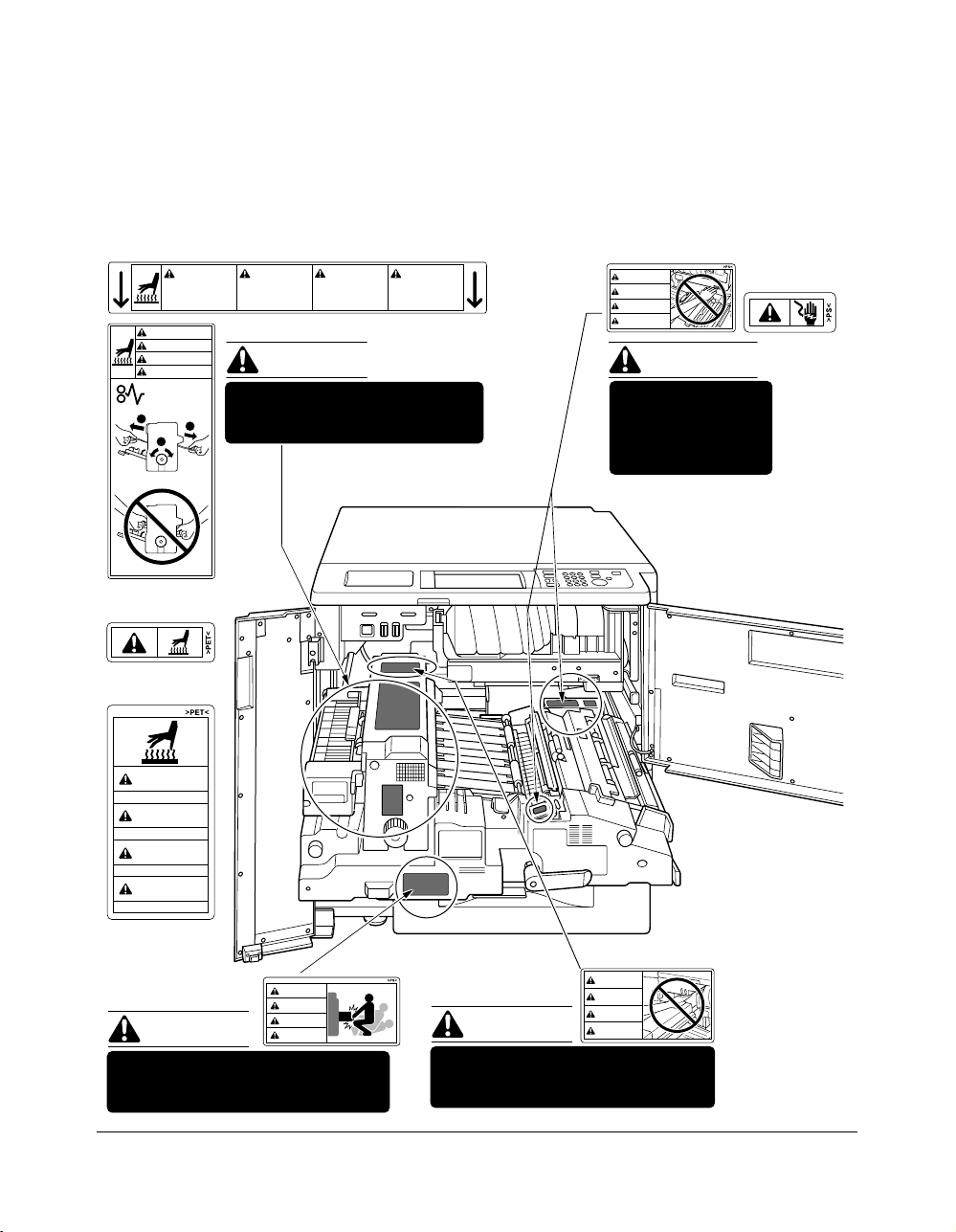
Label Locations
CAUTION
This internal area is very
hot. To avoid getting
burned, DO NOT TOUCH.
CAUTION
ATTENTION
PRECAUCION
CUIDADO
ATTENTION
Cette zone interne est
très chaude. Pour éviter
de se brûler, NE PAS LA
TOUCHER.
(Both sides of the fixing unit)
CAUTION
PRECAUCION
Esta zona interior está
muy caliente. Para no
quemarse NO TOCAR.
The fixing unit is very hot.
2
1
To avoid getting burned DO NOT
2
TOUCH.
(Top surface of
the fixing unit)
(Inside of
the fixing unit)
CAUTION
High temperature!
ATTENTION
Température élevée!
PRECAUCION
¡Temperatura alta!
CUIDADO
Alta temperatura!
(Front side of
the fixing unit)
CAUTION
ATTENTION
CAUTION
PRECAUCION
CUIDADO
The conveyance fixing unit is heavy.
Use care and draw it out gently;
otherwise you may be injured.
CUIDADO
Alta temperatura. NÃO
TOQUE nesta área
interior, pois há risco de
queimadura.
CAUTION
DO NOT put your hand between the
main body and developing fixing
unit; otherwise you may be injured.
WARNING
DANGER
ADVERTENCIA
ADVERTÊNCIA
WARNING
This area generates
high voltage. If
touched, electrical
shock may occur. DO
NOT TOUCH!
CAUTION
ATTENTION
PRECAUCION
CUIDADO
Safety Information 2-3
Page 16
Safety Information
Machine Safety Labels (continued)
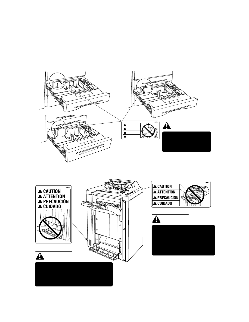
Label Locations (continued)
Tray 3
Tray 1
CAUTION
ATTENTION
PRECAUCION
CUIDADO
Tray 2
CAUTION
DO NOT put your hand
between the main body
and tray; otherwise you
may be injured.
(FN-104/FN-4)
CAUTION
(FN-4 only)
CAUTION
Inside the lower paper exit outlet
is the roller drive unit.
DO NOT put your hand into it;
otherwise you may be injured.
2-4 Safety Information
Use care after opening the
paper exit outlet. DO NOT
put your hand into it;
otherwise you may be
injured.
FN-4 Finisher
Page 17
Safety Information
Installation and Power Requirements
CAUTION:
FAILURE TO HEED THE FOLLOWING CAUTIONS MAY RESULT IN BODILY INJURY AND/OR
MACHINE DAMAGE
❒ FIRE PREVENTION
Install machine away from flammable or volatile materials. Routinely check for abnormal
heat from power cord and/or plug.
❒ SHORT CIRCUIT FROM WATER DAMAGE
Do not install or operate this equipment outdoors near a lake, pond, or river, etc.; and do
not allow the machine to come in contact with splashes of rain, water, or any liquid.
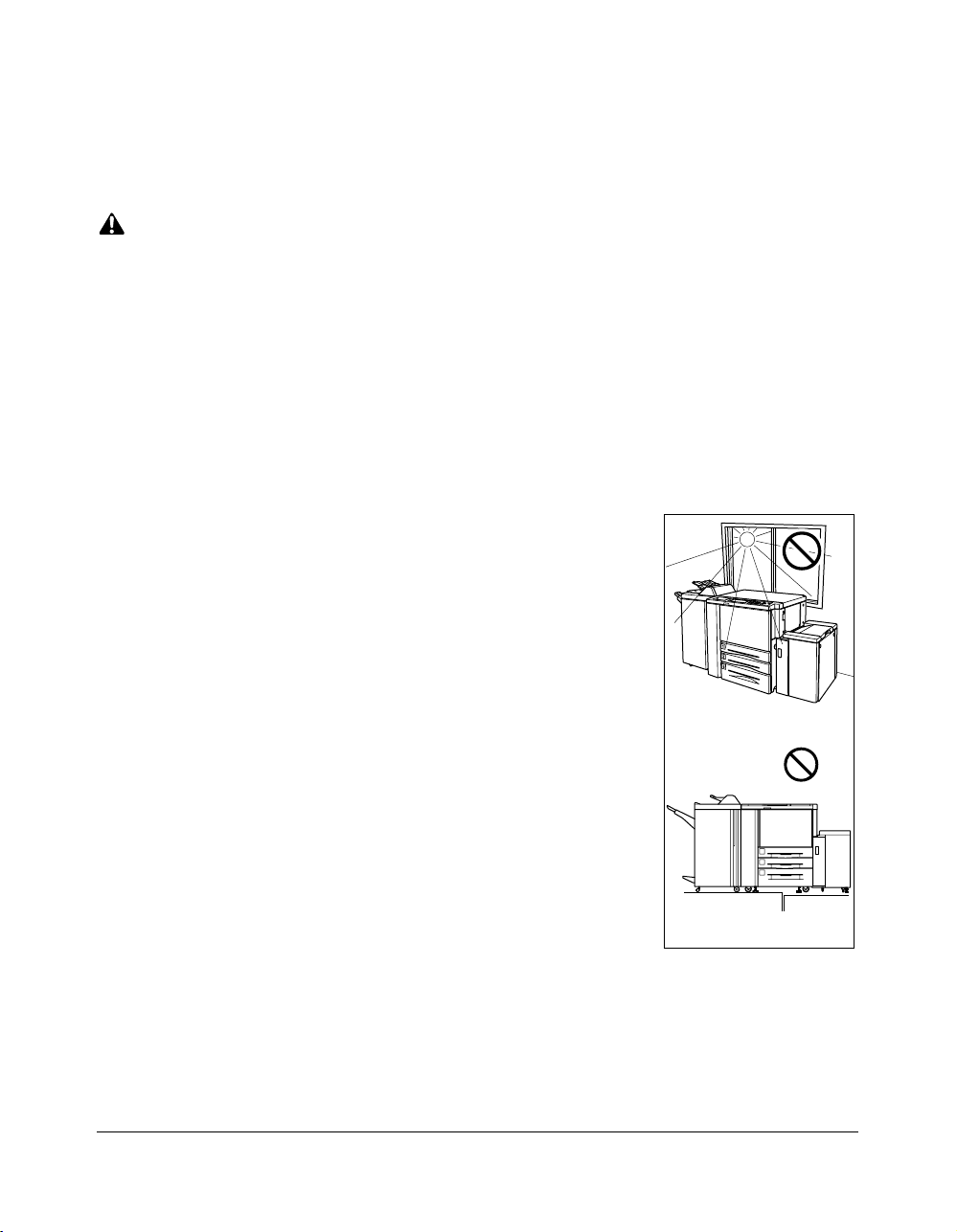
❒ TEMPERATURE AND HUMIDITY
Install the machine away from direct sunlight, heat sources
(stoves, heaters) and cold temperatures (air conditioners).
Avoid any environment that is outside 50°~86°F (10°~30°C),
with 10~80% humidity.
❒ VENTILATION
Do not allow the machine to come in contact with dust or
ammonia gas, or fumes from printing or cleaning solutions,
etc.; otherwise, image quality will be poor. Install the machine
in a well-ventilated area, for comfort; otherwise, an ozone odor
will be detected during large print runs. When in use, the
printer generates ozone in amounts too small to be hazardous
to the human body.
Temperature
❒ VIBRATIONS
If the machine is constantly vibrated or jolted, trouble may
occur. Install the machine on a level, horizontal floor, free from
vibrations.
❒ SPACE ALLOTMENT
Vibration
Install machine in an area with adequate space for performing printer operations,
replacing supply items, and conducting preventive maintenance. See Site Requirements,
Section 3.
❒ MACHINE RELOCATION
Before moving the machine to another location, contact your service representative.
Safety Information 2-5
Page 18

Safety Information
Installation and Power Requirements (continued)
CAUTION:
FAILURE TO HEED THE FOLLOWING CAUTIONS MAY RESULT IN MACHINE DAMAGE,
OVERHEATING, RISK OF ELECTRICAL SHOCK, AND/OR PERSONAL INJURY
PLUG SOCKET
A plug socket is limited in capacity. Use an exclusive power source for this machine;
otherwise, overheating and/or smoking may occur. The total power consumption of the
main body, plus all peripherals, must not exceed the capacity of the main power supply.
Be sure the socket outlet is near the equipment and is easily accessible.
PLUG AND CORD (LEAD)
Unless the power plug is firmly inserted into the socket, an accident from overheating
and/or smoking may occur. Firmly insert the power cord plug into the electrical outlet
before turning on the printer power switch. If the inserted plug is loose in the socket,
disconnect it, and consult an electrician for repair; but, do not attempt to operate the
machine. Be sure the socket outlet is near the equipment and is easily accessible.
A damaged power cord may result in overheating, short circuit or fire. Do not bend,
crush, wind, kick or strike the cord with any item. Do not roll up the cord. If the main body
power cord is bent or damaged, immediately contact your service representative; do not
attempt to repair it yourself, or continue to operate the machine.
ADAPTERS AND PLURAL LOADS
Never use adapters and never connect plural loads or a branched socket to one socket
outlet; otherwise, overheating or fire may occur.
EXTENSION CORDS (LEADS)
An extension cord or lead is limited in capacity. Unless the cord or lead has adequate
capacity, smoking and overheating may occur. Should smoking and/or overheating
occur, contact an electrician immediately. If you require further information about power
requirements, power consumption, extension cords, adapters and connectors, please
contact your service representative, and consult your electrician.
2-6 Safety Information
Page 19

Safety Information
Machine Handling and Care
WARNING:
FAILURE TO HEED THE FOLLOWING WARNING MAY RESULT IN DEATH OR SERIOUS INJURY AND/
OR MACHINE DAMAGE
MACHINE CONTACT
Never touch internal high voltage area indicated with a WARNING label.
Never touch the drum surface.
Never put your hand into the developing unit when removing mishandled paper.
CAUTION:
FAILURE TO HEED THE FOLLOWING CAUTIONS MAY RESULT IN MACHINE DAMAGE,
OVERHEATING, AND/OR PERSONAL INJURY
MACHINE CONTACT
Never touch internal high temperature or magnetism areas indicated with a CAUTION
label. Never insert your hand into the fixing unit when removing paper. Never touch the
inside of the main body for any purpose except moving mishandled paper or adding
toner. Use care when withdrawing the conveyance fixing unit.
MACHINE CARE
Do not drop paper clips, staples or other small metallic objects into the printer, or spill
water or any other liquid into the machine.
Do not use the machine surface to support vases, books, etc. These items will interfere
with the work space and may cause damage to the machine or to original documents.
ABNORMAL CONDITIONS
If any abnormal sound, odor, or smoke generates from the machine, immediately stop
using the printer, turn off the main power switch, disconnect the plug and contact your
service representative.
If a circuit breaker is tripped, or if a fuse blows, stop using the machine and contact an
electrician. If more detailed information is needed regarding the power source or power
consumption of this machine, contact your service representative.
MACHINE MODIFICATION
Do not modify the machine in any way or remove any part or screw. Never attempt to
perform any maintenance function that is not specifically described in this manual. Do
not connect the machine with any options other than those specified.
Safety Information 2-7
Page 20

Safety Information
Routine Safety
CAUTION:
FAILURE TO HEED THE FOLLOWING CAUTIONS MAY RESULT IN MACHINE DAMAGE,
OVERHEATING, AND/OR PERSONAL INJURY
PERIODIC CHECK
Check for loose connection or excessive heat on power plug, damage to power cord
and/or plug (creased, frayed, scratched or cut, etc.). Be sure the plug is inserted fully,
and ground wire is connected correctly. If any abnormality occurs, do not continue to
operate the machine.
SERVICE MESSAGES
If a service message displays, turn the machine off, disconnect the power cord from the
outlet, and report the condition to your service representative.
TONER
Check to be sure toner in storage is out of the reach of children, or anyone who may be
incapable of handling it in a safe manner. Although toner is nontoxic, do not inhale or
swallow toner or allow it to come in contact with eyes. If toner is inhaled, consult a
physician immediately. If swallowed, drink plenty of water and consult a physician
immediately. If eye contact occurs, flush eyes with plenty of water and consult a
physician immediately.
PAPER
Check paper to be sure it is according to the specifications outlined in Section 4.
CLEANING MATERIALS
Check the type of cleaning material used on your machine to be sure it is recommended
by us. If necessary, check with your service representative. Never use cleaning
materials for purposes other than cleaning, and be sure to keep all cleaning materials
out of the reach of children or anyone who is incapable of using them safely.
ENERGY SAVER
Use Energy Saver mode for short periods of machine inactivity. When not using the
machine for long periods of time, turn power off, unless the weekly timer function is
operating.
DISPOSAL OF THE PRINTER
Dispose of this printer according to your local regulations.
2-8 Safety Information
Page 21

Safety Information
Finisher Capacity Requirements
CAUTION:
FAILURE TO HEED THE FOLLOWING CAUTIONS MAY RESULT IN BODILY INJURY AND/OR
MACHINE DAMAGE
FINISHER PAPER CAPACITY
To prevent paper misfeed, do not exceed the paper capacity of the Finisher.
FN-104/FN-4 Finisher paper weight: 60~90g/m
When the selected print quantity exceeds the maximum paper capacity, remove sheets
as they are output from the finisher.
Paper capacities below are stated for 80g/m2. This Finisher also accepts the wide
orientation of regular sizes stated below.
Finisher FN-104/FN-4
Primary (Main) tray: Non-sort/Sort/Group mode
500 sheets (A5, A5R)
3,000 sheets (A4, A4R, B5, B5R)
1,500 sheets (A3, B4, F4)
The Secondary (sub) tray can be unloaded while the Di750PE is running.
Set production is not limited by the capacity of the Secondary (sub) tray.
2
Primary (Main) tray: Staple-Sort mode
1,000 sheets* (A3, B4, F4, A4, A4R, B5, A5)
* The maximum capacity varies according to the number of sheets to be
stapled.
Secondary (Sub) tray: Non-sort mode
200 sheets max. (A3, B4, F4, A4, A4R, B5, B5R, A5, A5R, B6R, A6R)
Booklet tray (FN-4 only)
100 sheets max. (A3, B4, A4R)
(The maximum number of sheets varies, depending on the number of pages in
the booklet and whether Folding or Stapling & Folding is selected.)
Trimming unit tray (FN-4 with TMG-1 only)
512 sheets max. (A3, B4, A4R, 8.5"x11"R)
(The maximum number of sheets varies, depending on the number of pages in
the booklet and whether Folding or Stapling & Folding is selected. See p. 4-7.)
Safety Information 2-9
Page 22

Safety Information
Finisher Capacity Requirements (continued)
CAUTION:
FAILURE TO HEED THE FOLLOWING CAUTIONS MAY RESULT IN BODILY INJURY AND/OR
MACHINE DAMAGE
FN-4 FINISHER BOOKLET MODE OUTLET
Inside the Booklet mode outlet is the roller drive unit. DO NOT put your hand into it when
removing the folded or stapled & folded sheet; otherwise you may be injured.
FN-104/FN-4 FINISHER PAPER EXIT OUTLET
To avoid injury when stapling large size prints, DO NOT put your hand into the open
Paper exit outlet.
2-10 Safety Information
Page 23

Safety Information
Regulations
CE Marking (Declaration of Conformity)
This product complies with the following EU directives:
89/336/EEC, 73/23/EEC and 93/68/EEC directives.
This declaration is valid for the area of the European Union.
This device must be used with shielded interface cables. The use of nonshielded cable is likely to result in interference with radio communications and
is prohibited under EU directives.
Safety Information 2-11
Page 24

Safety Information
Regulations (continued)
Regulations except Europe
Laser Safety
This is a digital machine which operates by means of a laser. There is no possibility of
danger from the laser, provided the machine is operated according to the instructions in
this manual.
Since radiation emitted by the laser is completely confined within protective housing, the
laser beam cannot escape from the machine during any phase of user operation.
This machine is certified as a Class 1 laser product. This means the machine does not
produce hazardous laser radiation.
For Users in Countries Subject to Class B Regulations
This device must be used with shielded interface cables. The use of nonshielded cable is likely to result in interference with radio communications and
is prohibited under CISPR 22 rules and local rules.
For Users in Countries not Subject to Class B Regulations
WARNING:
This is a Class A product. In a domestic environment this product may cause
radio interference in which case the user may be required to take adequate
measures.
This device must be used with shielded interface cables. The use of nonshielded cable is likely to result in interference with radio communications and
is prohibited under CISPR 22 rules and local rules.
2-12 Safety Information
Page 25
Safety Information
Regulations (continued)
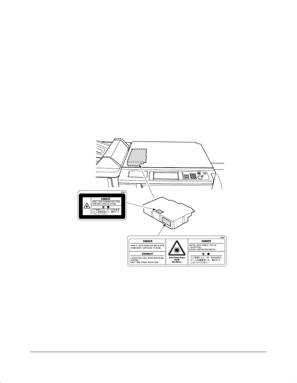
Internal Laser Radiation
Maximum Average Radiant Power: 1220 µW at the laser aperture of the print head unit.
Wavelength: 665-695 nm
This product employs a Class IIIb Laser Diode that emits an invisible laser beam.
The Laser Diode and Scanning Polygon Mirror are incorporated in the print head unit.
The print head unit is NOT A FIELD SERVICE ITEM.
Therefore, the print head unit should not be opened under any circumstances.
Printer head unit
Safety Information 2-13
Page 26

Safety Information
Regulations (continued)
Internal Laser Radiation (continued)
For the United States
CDRH regulation
This machine is certified as a Class 1 Laser product under the Radiation Performance
Standard according to the Food, Drug and Cosmetic Act of 1990. Compliance is
mandatory for Laser products marketed in the United States and is reported to the
Center for Devices and Radiological Health (CDRH) of the U.S. Food and Drug
Administration of the U.S. Department of Health and Human Services (DHHS). This
means that the device does not produces hazardous laser radiation.
The label shown on page 2-15 indicates compliance with the CDRH regulations and
must be attached to laser products marketed in the United States.
CAUTION:
Use of controls, adjustments or performance of procedures other than those specified in
this manual may result in hazardous radiation exposure.
This is a semiconductor laser. The maximum power of the laser diode is 20 mW and the
wavelength is 665-695 nm.
For European Users
CAUTION:
Use of controls, adjustments or performance of procedures other than those specified in
this manual may result in hazardous radiation exposure.
This is a semiconductor laser. The maximum power of the laser diode is 20 mW and the
wavelength is 665-695 nm.
For Denmark Users
ADVARSEL
Usynlig laserstråling ved åbning, når sikkerhedsafbrydere er ude af funktion. Undgå
udsættelse for stråling. Klasse 1 laser produkt der opfylder IEC60825 sikkerheds kravene.
Dansk: Dette er en halvlederlaser. Laserdiodens højeste styrke er 20 mW og
bølgelængden er 665-695 nm.
2-14 Safety Information
Page 27
Safety Information
Regulations (continued)
Internal Laser Radiation (continued)
For Finland, Sweden Users
LOUKAN 1 LASERLAITE
KLASS 1 LASER APPARAT
VAROITUS!
Laitteen Käyttäminen muulla kuin tässä käyttöohjeessa mainitulla tavalla saattaa
altistaa käyttäjän turvallisuusluokan 1 ylittävälle näkymättömälle lasersäteilylle.
Tämä on puolijohdelaser. Laserdiodin suurin teho on 20 mW ja aallonpituus on 665-695 nm.
VARNING!
Om apparaten används på annat sätt än i denna bruksanvisning specificerats, kan
användaren utsättas för osynlig laserstrålning, som överskrider gränsen för laserklass 1.
Det här är en halvledarlaser. Den maximala effekten för laserdioden är 20 mW och
våglängden är 665-695 nm.
VARO!
Avattaessa ja suojalukitus ohitettaessa olet alttiina näkymättömälle lasersäteilylle. Älä
katso säteeseen.
VARNING!
Osynlig laserstrålning när denna del är öppnad och spärren är urkopplad. Betrakta ej
strålen.
For Norway Users
ADVERSEL
Dersom apparatet brukes på annen måte enn spesifisert i denne bruksanvisning, kan
brukeren utsettes for unsynlig laserstråling som overskrider grensen for laser klass 1.
Dette en halvleder laser. Maksimal effekt till laserdiode er 20 mW og bølgelengde er
665-695 nm.
Safety Information 2-15
Page 28
Safety Information
Regulations (continued)
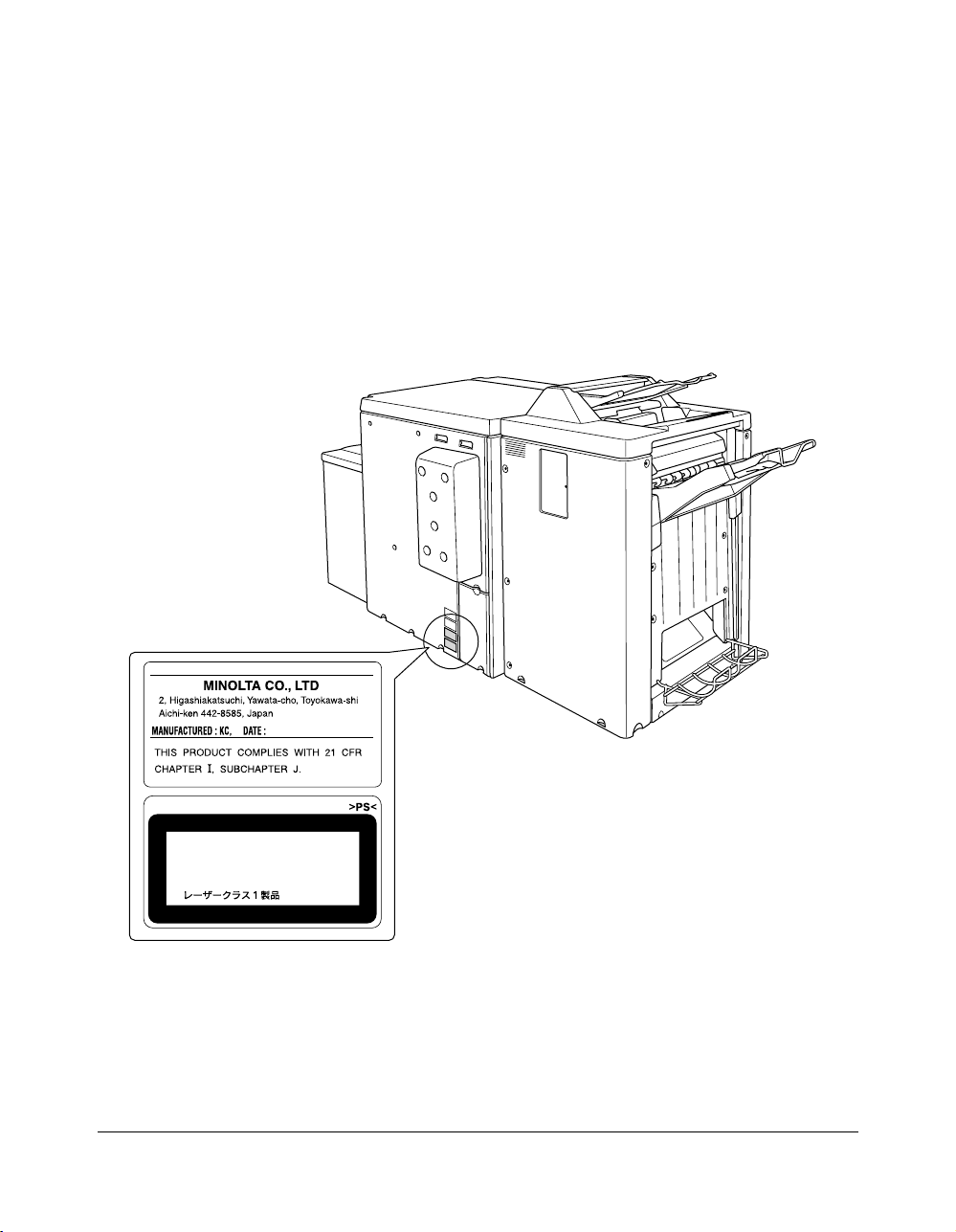
Laser Safety Label
A laser safety label is attached to the outside of the machine as shown below.
CLASS 1 LASER PRODUCT
APPAREIL A RAYONNEMENT
LASER DE CLASSE 1
LASER KLASSE 1
2-16 Safety Information
Page 29

Safety Information
Regulations (continued)
Ozone Release
NOTE
= Locate the Machine in a Well Ventilated Room =
A negligible amount of ozone is generated during normal operation of this machine. An
unpleasant odor may, however, be created in poorly ventilated rooms during extensive
machine operations. For a comfortable, healthy, and safe operating environment, it is
recommended that the room well ventilated.
REMARQUE
= Placer l’appareil dans une pièce largement ventilée =
Une quantité d’ozone négligable est dégagée pendant le fonctionnement de l’appareil
quand celui-ci est utilisé normalement. Cependant, une odeur désagréable peut être
ressentie dans les pièces dont l’aération est insuffisante et lorsque une utilisation
prolongée de l’appareil est effectuée. Pour avoir la certitude de travailler dans un
environnement réunissant des conditions de confort, santé et de sécurité, il est
préférable de bien aérer la pièce ou se trouve l’appareil.
Acoustic Noise
For European Users
Machine Noise Regulation 3 GSGV, 18.01.1991: The sound pressure level at the
operator position according to EN 27779 is equal to or less than 70dB(A).
Safety Information 2-17
Page 30

Section 3: Machine Information
Di750PE Overview ....... 3-2
Key Operator Functions......... 3-3
Service, Repairs and Supplies......... 3-3
Machine Labels......... 3-3
Service Settings......... 3-4
External Machine ....... 3-5
Internal Machine ....... 3-7
Standard Equipment ....... 3-8
Optional Equipment ....... 3-8
Finisher/Large Capacity Cassette....... 3-10
Trimming Unit....... 3-11
Punch Kit....... 3-12
Site Requirements ..... 3-13
Specifications ..... 3-14
Machine Information 3-1
Page 31

Machine Information
Di750PE Overview
The built-in electronic recirculating document handler (ERDH) provides dual access
capability, enabling the printer to receive a job while another job is printing or rasterizing.
This timesaving system allows you to work with optimal efficiency while the printer is
operating at peak capacity.
The advanced finishing system of the Di750PE provides you with the option of sending
print jobs to the output tray face down and in correct order.
Highlights of the Di750PE include:
• 75 ppm
• 600 dpi
• duplex mode
• 3 standard paper trays plus a Multi-sheet bypass tray
• LCC, Finisher and Trimming Unit and Punch Kit
3-2 Machine Information
Page 32

Machine Information
Di750PE Overview (continued)
Key Operator Functions
Access to the Key Operator mode may require entry of a Key Operator password
previously set by your service representative. A Key Operator may make various custom
settings that affect printer functions. We recommend using a password to limit access to
the Key Operator mode to an authorized person.
Service, Repairs & Supplies
Service and repairs should be performed only by an authorized service representative.
To maintain personal safety and to avoid machine damage, never disassemble the
machine for any reason. To ensure optimal printing quality, use only supplies that are
recommended by us.
Machine Labels
Machine labels are affixed to provide quick and easy instructions on loading paper,
adding toner, and clearing mishandled paper. Machine safety labels, affixed to key areas
of the internal machine, provide cautionary information to prevent personal injury or
damage to the equipment. Sample machine safety labels are shown in the
Information
section.
Safety
Machine Information 3-3
Page 33

Machine Information
Di750PE Overview (continued)
Service Settings
Setting changes for the following functions can be made by your service representative.
Finisher-Paper Capacity
In the default condition, the Di750PE will produce unlimited sets. If required, your service
representative can set the printer to stop printing when the number of prints exceeds
specified capacity.
Key Operator Password
Your service representative can set a 4-digit Key operator password to access the Key
Operator Mode Screen.
After this setting is made, a Password Entry Screen will be displayed when Key Operator
mode is selected from the Help Screen. The user or Key Operator will be required to
enter the valid Key Operator password before accessing the Key Operator Mode
Screen. It is recommended that the Key Operator password be noted and kept in a
secure place in the event it is forgotten. Otherwise, you will be required to contact your
service representative to obtain a password.
Weekly Timer
Your service representative can set a 4-digit Weekly timer master key code to enable
the Key Operator to gain access to the Weekly Timer Setting Menu Screen.
After this setting is made, the Weekly Timer Master Key Code Screen will be displayed
and will always require entry of the set Weekly Timer master key code to access the
Weekly Timer Setting Menu Screen.
Your service representative can set the Weekly Timer system to display the Weekly
Timer key on the Help Screen which enables you to view Weekly Timer settings.
Staple Sheet Capacity
Staple capacity is changeable, and may be set to 45, 40, or 35 by your service
representative.
Notice Message for ADD TONER/ PM CALL
Your service representative can set the printer message area to display “ADD TONER”
when the toner supply is low, or “PM CALL” when preventive maintenance is required.
3-4 Machine Information
Page 34

Machine Information
External Machine
!5FN-104/FN-4
Finisher (option)
!2Power switch
!1Left side cover
(not shown)
!0Front door
oLeft door
!6LCD touch screen
iTray 1
uTray 2
tRight side door (not shown)
yTray 3
!7Control panel
rLCC left side
door
qMulti-sheet
bypass tray
wLCC top door
eTray 4 : Large capacity
cassette C-305 (option)
1 Multi-sheet bypass tray used for small quantity printing onto plain paper or special paper.
2 LCC top door opens to allow loading paper.
3 Tray 4: Large capacity cassette C-305 option holds 4,000 sheets.
4 LCC left side door opens to allow removal of mishandled paper.
5 Right side door opens to allow removal of mishandled paper.
6 Tray 3 (universal tray) is user adjustable and holds 1,000 sheets.
7 Tray 2 (universal tray) is user adjustable and holds 500 sheets.
8 Tray 1 (universal tray) is user adjustable and holds 500 sheets.
NOTE: Tray 1, 2, 3, and 4 are available for loading wide types of the regular sizes specified above.
9 Left door opens together with the front door to allow removal of mishandled paper.
10 Front door opens to the internal printer to allow clearing of mishandled paper and
replenishing of toner.
11 Left side cover opens to allow removal of mishandled paper.
12 Power switch turns printer power On/Off when pressed.
13 TMG-1 Trimming unit (See next page.)
14 Trimmer stacker cover (See next page.)
15 FN-104/FN-4 Finisher (option) sorts, staple-sorts, and groups into finished sets. FN-4 also
folding or stapling & folding prints into booklet-styled sets.
16 LCD touch screen displays interactive operation screens.
17 Control panel controls printer operations.
Machine Information 3-5
Page 35

Machine Information
External Machine (continued)
!5FN-4 Finisher (option)
!4Trimmer
stacker cover
!3TMG-1 Trimming unit
(option)
!6PK-1 Punch Kit (option)
wLCC top door
rLCC left side door
eTray 4: Large
capacity cassette
C-305L (option)
2 LCC top door opens to allow loading paper.
3 Tray 4: Large capacity cassette C-305L option holds 4,000 sheets.
4 LCC left side door opens to allow removal of mishandled paper.
13 TMG-1 Trimming unit (option) trims the end of booklet.
14 Trimmer stacker cover opens to allow you to take out the finished sets.
15 FN-4 Finisher (option) sorts, staple-sorts, and groups into finished sets. FN-4 also folds or
staples & folds prints into booklet-styled sets.
16 PK-1 Punch Kit (option) punches file holes in the output prints.
3-6 Machine Information
Page 36

Machine Information
Internal Machine
iConveyance part
qToner cartridge
wToner unit
uFixing part
yKnob
eDrum unit
rLever A
tConveyance/Fixing unit
1 Toner cartridge holds toner and must be replaced when refilling toner.
2 Toner unit holds the toner supply.
3 Drum unit forms the print image.
4 Lever A can be moved to withdraw the conveyance fixing unit for removal of mishandled
paper.
5 Conveyance/Fixing unit passes the paper through the drum unit, and fuses the toner onto
the print paper, and must be withdrawn for removal of mishandled paper.
6 Knob can be turned to ease removal of mishandled paper from the fixing unit.
7 Fixing part
8 Conveyance part
Machine Information 3-7
Page 37

Machine Information
Standard Equipment
Main Body with 3 Paper Trays (500/500/1,000 sheets)
Automatic Duplex Unit (ADU)
Multi-Sheet Bypass Tray (150 Sheets)
Optional Equipment
FN-104 Stapler Finisher (with 2 exit trays)
Secondary (sub) tray with 4 output types specified on Finisher Mode Selection Screen
(1) Face down non-sort exit
(2) Face up non-sort exit
(3) Face down group exit
(4) Face up group exit
Primary (main) tray with 4 output types specified by STAPLE SORT and SORT keys
on the Basic Screen and by the setting on the Finisher Mode Selection Screen. Face
up exit is not available.
(1) Sort exit
(2) Staple sort exit
(3) Non-sort exit
(4) Group exit
FN-4 Stapler Finisher (with 3 exit trays and a cover sheet feeder option)
Secondary (sub) tray with 4 output types specified on Finisher Mode Selection Screen
(1) Face down non-sort exit
(2) Face up non-sort exit
(3) Face down group exit
(4) Face up group exit
Primary (main) tray with 4 output types specified by STAPLE SORT and SORT keys
on the Basic Screen and by the setting on the Finisher Mode Selection Screen. Face
up exit is not available.
(1) Sort exit
(2) Staple sort exit
(3) Non-sort exit
(4) Group exit
Booklet tray: Stapled and folded, or simply folded booklets are to be delivered onto this
tray.
Trimming unit tray: This tray is attached to a trimming unit (option) installed on the
stapler finisher (FN-4). Folded or stapled and folded trimmed booklets are delivered to
this tray.
3-8 Machine Information
Page 38

Machine Information
Optional Equipment (continued)
Punch Kit (PK-1)
Cover Inserter A
Trimming Unit (TMG-1)
Large Capacity Cassette (C-305)
Large Capacity Cassette (C-305L)
64MB Memory (M64-1)/128MB Memory (M128-1)
Machine Information 3-9
Page 39

Machine Information
Optional Equipment (continued)
Finisher/Large Capacity Cassette
FN-104/FN-4 Finisher details
Cover Inserter A (option):
Holds cover sheets for use in Cover
Sheet output mode or a printed set in
manual stapling mode.
Primary (main) tray:
Holds sets ejected in
q Sort mode (offset)
w Staple-sort mode
e Group mode (offset)
Secondary (sub) tray:
Holds sets ejected in
q Non-sort Face Down exit mode
w Non-sort Face Up exit mode
e Group Face Down exit mode
r Group Face Up exit mode
Manual staple control panel
Finisher door
Booklet mode outlet (FN-4 only):
ejects finished printed sets when selecting
Folding mode or Stapling & Folding mode.
Booklet tray (FN-4 only)
Large Capacity Cassette details
Paper guides:
hold print paper to
fix its position.
Paper loading button:
is pressed to lower the bottom
plate to allow loading paper.
C-305
style
Bottom plate of the LCC:
goes up automatically when paper
supply becomes low, and goes
down when the paper loading
button is pressed.
C-305L style
Rear stopper:
fixes the rear end of
print paper.
LCC top door:
opens to load paper.
LCC left side door:
opens to allow removal of
mishandled paper.
LCC lever:
can be moved downward to ease
removal of mishandled paper.
C-305L style
C-305L
style
3-10 Machine Information
Page 40

Machine Information
Optional Equipment (continued)
Trimming Unit
TMG-1 Trimming Unit
Trimming Unit tray:
slides to the left side
each time a trimmed
booklet is delivered.
Trimming Unit knob:
can be turned to ease removal
of mishandled paper.
Trimmer pressure
release lever:
opens to allow removal
of mishandled paper.
FN-4 Finisher
Trimmer stacker cover:
opens to allow you to
take out the finished sets.
Trimmer stacker
Trash basket:
holds waste paper cut off
from the booklets.
Front-right cover:
opens to allow removal
of mishandled paper.
Front door:
opens to allow removal of
mishandled paper or waste
paper. (see details below)
NOTE:
DO NOT place heavy objects on the
trimmer stacker or apply any weight
on it, and DO NOT use it for storage.
Excessive weight applied to the
inside or outside of the trimmer
stacker will damage the equipment.
Machine Information 3-11
Page 41

Machine Information
Optional Equipment (continued)
Punch Kit
PK-1 Punch Kit
Punch kit knob:
can be turned to ease
removal of mishandled
paper.
Left lever:
opens downward to
allow removal of
mishandled paper.
Upper lever:
opens upward to allow
removal of mishandled
paper.
Right lever:
opens upward to allow
removal of mishandled
paper.
Trash basket:
holds waste paper punched
out.
Finisher/Punch kit
front door:
opens to remove mishandled
paper in Finisher or Punch kit,
to change the staple
cartridge and to remove
paper punched out.
3-12 Machine Information
Page 42

Machine Information
Site Requirements
3.9
12.65
(100)
(321)
39.0
(990)
21.7
(550)
18.7
(475)
71.4
(1814)
34.95
(887)
1
2
3
69.4
(1762)
34.95
(887)
11
2
3
92.3
(2344)
Di750PE + FN-104/FN-4 + C-305
15.75
(400)
15.2
(386)
4
20.9
(530)
Di750PE
3.9
(100)
39.0
(990)
37.4
(950)
37.4
(950)
Unit: inches (mm)
30.5
(775)
72.6
(1845)
Unit: inches (mm)
30.5
(775)
72.6
(1845)
4.7
(120)
4.7
(120)
5.9
(150)
44.0
(1117)
(2829)
21.6
(550)
111.4
6.65
(169)
141.7
(3599)
34.95
(887)
24.6
(626)
30.3
(770)
3.9
(100)
39.0
(990)
37.4
(950)
72.6
(1845)
30.5
(775)
Di750PE + FN-4 + PK-1 + TMG-1 + C-305L
NOTES:
1 Dimensions are in inches with millimeters included in parentheses.
2 The Finisher main tray of the FN-104/FN-4 Finisher gradually goes down while printed material is output.
DO NOT allow any object to interfere with the operation of the tray on the left side of the finisher, as
interference may cause damage to the finisher.
Machine Information 3-13
Unit: inches (mm)
4.7
(120)
Page 43

Machine Information
Specifications
Product Name Di750PE Network Printing System
Engine Type Dual Beam Laser, Electrostatic
Engine Speed 55 pages per minute (600dpi)
Recommended Operating Environment 50°~86°F (10°~30°C); 10~80% Relative
Humidity
Warm Up Approx. 6 min. @68°(20°C); 50% Relative
Humidity
Voltage 230V AC + 10.6%, –14%
Current 15A Dedicated line recommended
Frequency 50Hz/60Hz
Grounding Isolation recommended
Termination NEMA Type 6-20R receptacle
(250V, 2-pole, 3-wire, grounded)
Power Consumption Max. 3,450 VA (full option)
Noise Level (full system) Approx. 78 dB (A) or less, during printing
Main Body Safety Standard UL 1950; CSA 22.2 No. 950 -95
Laser Safety Standard FDA: CFR1040
3-14 Machine Information
Radio Interference FCC Rules part 15, sub-part B Class A
IC: ICES CSA C108.8 Class A
Toner Black, cartridge type
Paper Source Main body trays 1/2/3; 500/500/1,000 sheets
LCC tray 4; 4,000 sheets
Multi-sheet bypass tray; 150 sheets
Tray 1/2/3 user adjustable
Tray 4 adjusted by service
Paper Exit Tray 150 sheets (80g/m2)
Specifications subject to change without notice.
Page 44

Machine Information
Specifications (continued)
Paper Weight 80~90g/m2 bond recommended
Machine Weight 572 lb (260 kg)
Machine Dimensions Main Body
(Max. range: 60~170g/m2 in 2-2 mode
60~200g/m2 (200g/m2 thick paper) in 1-1mode
OHP sheet, Transparency, Labels, Tab, 4-hole
Options Finisher (FN-104/FN-4)
Cover Inserter A
Trimming Unit (TMG-1)
Large Capacity Cassette (LCC) (C-305)
Large Capacity Cassette (LCC) (C-305L)
64MB Memory (M64-1)
128MB Memory (M128-1)
+110 lb (50 kg) w/Stapler-Finisher
+66 lb (30 kg) w/Large Capacity Cassette
Width: 34.9 in. (887mm)
Depth: 30.5 in. (775mm)
Height: 39.0 in. (990mm)
Stapler-Finisher (FN-104/FN-4)
Width: 21.4 in. (544mm)
Depth: 25.8 in. (656mm)
Height: 43.1 in. (1095mm)
Cover Inserter A
Width: 13.0 in. (330mm)
Depth: 18.0 in. (456mm)
Height: 4.7 in. (120mm)
Trimming Unit (TMG-1)
Width: 44.0 in. (1117mm)
Depth: 23.8 in. (604mm)
Height: 22.1 in. (562mm)
Punch Kit (PK-1)
Width: 6.7 in. (169mm)
Depth: 26.0 in. (660mm)
Height: 39.0 in. (990mm)
Specifications subject to change without notice.
Machine Information 3-15
Page 45

Machine Information
Specifications (continued)
Automatic Duplex Unit (ADU) Paper size: A3, B4, F4, A4, A4R, B5, B5R, A5,
Stapling Finisher (FN-104/FN-4) Power source: Main body
A5R
Paper weight: 60~170g/m
2
Paper curl limit: 20 mm or less
Non-stack type
Non-sort/Sort/Group mode:
500 sheets A5, A5R
3000 sheets A4, A4R, B5, B5R
1500 sheets A3, B4, F4
Size A3 ~ A5R
Staple-sort mode: 1000 sheets*
Size A3, B4, F4, A4, A4R, B5, A5
* Variable according to the number of pages to
be stapled. See p. 4-5 for detail.
Folding/Stapling & Folding mode w/FN-4
100 sheets*
Size A3, B4, A4R
* The maximum number of sheets varies
depending on pages of a booklet and
selecting either the Folding or Stapling &
Folding. See p. 4-6.
3-16 Machine Information
Staple Cartridge 5000 staples/cartridge
Cover Inserter A Paper size : A3, B4, F4, A4, A4R, B5, A5
Paper weight in cover sheet mode: 50~200g/m
(200g/m2 thick paper)
Paper weight in manual staple: 60~90g/m
Specifications subject to change without notice.
2
2
Page 46

Machine Information
Specifications (continued)
Trimming Unit (TMG-1) A3, B4, A4R, 8.5"x11"R
Paper weight : 60~170g/m
2
* One 200g/m2 thick paper is available.
Number of trimmed sheets :
3 sheets max. with Folding mode
16 sheets max. with Stapling & Folding mode
(15 sheets max. when using a thick cover)
Trimmed width : 10 mm max.
Stack capacity : 512 sheets max.
* The maximum number of sheets varies,
depending on the number of pages in the
booklet and whether Folding or Stapling &
Folding is selected.
Power source: supply from outlet
Punch Kit (PK-1) Paper size: A3, B4, A4, B5
Paper weight: 60~170g/m
2
Number of hole: 4 holes
Hole diameter: 6.5mm ± 0.5mm
Hole pitch: 80mm ± 0.5mm
Weight: 77 lb (35 kg)
Power source: supply from outlet
Large Capacity Cassette (C-305) Plain paper (60~200g/m2 (200g/m2 thick
paper))
Paper size: A4, B5 or 8.5"x11"
Dimensions: Width 16.9 in (430 mm)
Depth 25.2 in (639 mm)
Height 27.2 in (690 mm)
Weight: 66 lb (30 kg)
Power source: supply from main body
Large Capacity Cassette (C-305L) Paper type: Plain paper (60~200g/m2 (200g/m
thick paper))
Paper size: A3, B4, F4, A4, A4R, 11"x17",
8.5"x14", 8.5"x11", 8.5"x11"R
Dimensions: Width 26.4 in (670 mm)
Depth 25.2 in (639 mm)
Height 27.4 in (695 mm)
Weight: 92.4 lb (42 kg)
Power source: supply from main body
Specifications subject to change without notice.
Machine Information 3-17
2
Page 47

Section 4: Media Information
Main Body Trays ....... 4-2
Large Capacity Cassette (C-305) (Option) ....... 4-3
Large Capacity Cassette (C-305L) (Option) ....... 4-3
Automatic Duplex Unit ....... 4-4
Multi-Sheet Bypass Tray and Tab Sheets ....... 4-4
FN-104/FN-4 Finisher (Option) ....... 4-5
Primary (Main) Tray......... 4-5
Secondary (Sub) Tray......... 4-5
FN-4 Finisher Booklet Tray......... 4-6
Cover Inserter A (Option) ....... 4-7
Paper in Punch Kit (PK-1) (Option) ....... 4-7
Paper in Trimming Unit (TMG-1) (Option) ....... 4-7
Paper Supply Message ....... 4-8
Paper Weight Compatibility Chart ....... 4-9
Media Information 4-1
Page 48

Media Information
Main Body Trays
Loading Paper Size : Max. 314mm (D) x 445mm (W) ~ Min. 100mm (D) x 148mm (W)
STD Size : A3, B4, F4, A4, A4R, B5, B5R, A5, 11"x17", 8.5"x14", 8.5"x11"
(user-adjustable)
STD Size (Special) : 8.5"x11"R instead of A4R
5.5"x8.5"/5.5"x8.5"R instead of A5/A5R
Non-STD Size : Max. 314mm (D) x 445mm (W) ~ Min. 210mm (D) x 140mm (W)
Wide Size : A3W, B4W, A4W, A4WR, B5W, A5W, 11"x17"W, 8.5"x11"W,
8.5"x11"WR, 5.5"x8.5"W
NOTE: STD size (Special) , Non-STD size, and Wide size settings for each tray can be made in key operator
mode. See p. 8-16~p. 8-17.
Paper Weight : General; 60~90g/m
Tray specified as Thick 1; 91~170g/m
Tray specified as Thick 2; 171~200g/m
Tray specified as Thin; 50~59g/m
Tray specified as TAB; 91~170g/m
NOTE: Paper type setting (Thick 1, Thick 2, Thin, or TAB) for each tray can be made in the Key operator
mode. See p. 8-16~p. 8-17.
Total Paper Capacity : 2,150 sheets, including 150-sheet Multi-sheet Bypass Tray
2
2
2
2
2
4-2 Media Information
Page 49

Media Information
Large Capacity Cassette (C-305) (Option)
STD Size : A4, B5 or 8.5"x11" (service-adjustable)
Non-STD Size : Max. 314mm (D) x 223mm (W) ~ Min. 257mm (D) x 182mm (W)
Wide Size : A4W, B5W, 8.5"x11"W
NOTE: Non-STD size, and Wide size settings for the tray can be made in key operator mode. See p. 8-16~p.
8-17.
Paper Weight : General; 60~90g/m
Tray specified as Thick 1; 91~170g/m
Tray specified as Thick 2; 171~200g/m
Tray specified as Thin; 50~59g/m
Tray specified as TAB; 91~170g/m
NOTE: Paper type setting (Thick 1, Thick 2, Thin, or TAB) for each tray can be made in the Key operator
mode. See p. 8-16~p. 8-17.
Total Paper Capacity : 6,150 sheets, including three Main body trays and 150-sheet
Multi-sheet Bypass Tray
Tray 4 (LCC) : 4,000 sheets 80g/m2 / fixed to A4/W, B5/W or 8.5"x11"/W
(service adjustable)
Large Capacity Cassette (C-305L) (Option)
2
2
2
2
2
STD Size : A3, B4, A4, A4R, 11"x17", 8.5"x14", 8.5"x11", 8.5"x11"R or F4
(service-adjustable)
Non-STD Size : Max. 314mm (D) x 459mm (W) ~ Min. 257mm (D) x 210mm (W)
Wide Size : A3W, B4W, A4W, A4RW, 11"x17"W, 8.5"x14"W, 8.5"x11"W,
8.5"x11"RW, F4W
NOTE: Non-STD size, and Wide size settings for the tray can be made in key operator mode. See p. 8-16~p.
8-17.
Paper Weight : General; 60~90g/m
Tray specified as Thick 1; 91~170g/m
Tray specified as Thick 2; 171~200g/m
Tray specified as Thin; 50~59g/m
Tray specified as TAB; 91~170g/m
NOTE: Paper type setting (Thick 1, Thick 2, Thin, or TAB) for each tray can be made in the Key operator
mode. See p. 8-16~p. 8-17.
2
2
2
2
2
Total Paper Capacity : 6,150 sheets, including three Main body trays and 150-sheet
Multi-sheet Bypass Tray
Tray 4 (LCT) : 4,000 sheets 80g/m2 / fixed to A3W, B4W, A4W, A4RW,
11"x17"W, 8.5"x14"W, 8.5"x11"W, 8.5"x11"RW, or F4W (service
adjustable)
Media Information 4-3
Page 50

Media Information
Automatic Duplex Unit
Paper Size : Max. 314mm (D) x 445mm (W) ~ Min. A5
NOTES: • Wide size paper can be conveyed into the ADU.
Paper Weight : 60~170g/m
Duplex Tray Capacity : Unlimited stackless duplex tray
NOTE: Reliability and copy quality are not guaranteed for all Special papers. Use only paper that is
Multi-Sheet Bypass Tray
Multi-sheet bypass tray accepts non-standard size or special paper type that cannot be
loaded in the main body trays or LCC.
Loading Paper Size : Max. 314mm (D) x 445mm (W) ~ Min. 100mm (D) x 148mm (W)
Specified Size Automatically : A3, B4, F4, A4, A4R, B5, B5R, A5, A5R, B6R, 11"x17",
Specified Size Manually/STD Size (Special) :
Specified Size Manually/Wide Size : A3W, B4W, A4W, A4WR, B5W, B5WR, A5W,
Paper Weight : General; 60~90g/m
NOTE: Paper type and size should be specified on the Special Paper Type/Size Setting Screen. See p. 5-10.
• Non-STD size paper cannot be conveyed into the ADU.
• A5 copy paper is available in crosswise orientation feeding only.
2
recommended by us.
8.5"x14", 8.5"x11", 8.5"x11"R, 5.5"x8.5"R
A5WR, B6WR, 11"x17"W, 8.5"x14"W, 8.5"x11"W,
8.5"x11"WR, 5.5"x8.5"WR
2
Tray specified as Thick; 91~170g/m
Tray specified as Thin; 50~59g/m
Tray specified as TAB; 91~170g/m
2
2
2
Multi-Sheet Bypass Tray Capacity : 150 sheets 80g/m2; 1 sheet (OHP film)
4-4 Media Information
Page 51

Media Information
FN-104/FN-4 Finisher (Option)
FN-104/FN-4 Finisher accepts A3, B4, F4, A4, A4R, B5, B5R, A5, A5R, B6R and A6R
paper sizes. The finisher tray capacities classified according to paper size in each output
mode are described below.
Primary (Main) Tray
In-Bin Stapler Finisher FN-104/FN-4 (capacities at 20 lb, unless otherwise indicated)
Non-sort/Sort/Group mode:
500 sheets A5/A5W, A5R/A5WR
(5.5"x8.5"/5.5"x8.5"W, 5.5"x8.5"R/5.5"x8.5"WR)
3,000 sheets A4/A4W, A4R/A4WR, B5/B5W, B5R/B5WR
(8.5"x11"/8.5"x11"W, 8.5"x11"R/8.5"x11"WR)
1,500 sheets A3/A3W, B4/B4W, F4
(11"x17"/11"x17"W, 8.5"x14")
Staple-sort mode:
1,000 sheets* A3/A3W, B4/B4W, F4, A4R/A4WR, A4/A4W, B5/B5W, A5/A5W
(11"x17"/11"x17"W, 8.5"x14", 8.5"x11/8.5"x11"W, 8.5"x11"R/
8.5"x11"WR)
NOTE: *Variable according to the number of pages to be stapled. See the table below.
Paper Capacity for Staple-sort mode of Finisher FN-104/FN-4
No. of pages
2~9
10~20
21~30
31~40
41~50
Service can set the copier to stop copying when the number of copies
exceeds above capacity. Contact your service representative.
(for the same size only)
A3
2 staples
50 sets
1 staple
50 sets
50
30
25
20
B4, F4, A4, A4R, B5, A5
2 staples
100 sets
50
30
25
20
1 staple
100 sets
50
30
25
20
50
30
25
20
Secondary (Sub) Tray
In-Bin Stapler Finisher FN-104/FN-4 (capacities at 80g/m2, unless otherwise
indicated)
200 sheets; max. 314mm (D) x 445mm (W) ~ min. 100mm (D) x 148 mm (W)
CAUTION:
When the selected print quantity exceeds the Finisher’s maximum capacity, remove the printed sheets
while paper is exiting to avoid paper mishandling.
Media Information 4-5
Page 52

Media Information
FN-104/FN-4 Finisher (Option) (continued)
FN-4 Finisher Booklet Tray
Folding mode:
STD Size : A3, B4, A4R
(11"x17", 8.5"x14", 8.5"x11"R)
Wide Size : A3W, B4W, A4WR
(11"x17"W, 8.5"x11"WR)
Paper Weight : 60~90g/m2 paper (80g/m2 paper is recommended)
Number of Folded Sheet : 3 sheets max.
Booklet Tray Capacity : Approx. 100 sheets max.
33 sets max. of 3-sheet-folded booklet
(33 x 3 = 99 sheets)
50 sets max. of 2-sheet-folded booklet
(50 x 2 = 100 sheets)
Stapling & Folding mode:
STD Size : A3, B4, A4R
(11"x17", 8.5"x14", 8.5"x11"R)
Wide Size : A3W, B4W, A4WR
(11"x17"W, 8.5"x11"WR)
Paper Weight : 60~90g/m2 paper (80g/m2 paper is recommended)
one cover paper only (91~200g/m2 paper)
Number of Folded Sheet : 16 sheets max. (using 80g/m2 paper only)
15 sheets max. (using one cover paper)
Booklet Tray Capacity : Approx. 100 sheets max.
20 sets max. of 5-sheet-folded booklet
(20 x 5 = 100 sheets)
10 sets max. of 10-sheet-folded booklet
(10 x 10 = 100 sheets)
6 sets max. of 16-sheet-folded booklet
(6 x 16 = 96 sheets)
CAUTION:
Inside the Booklet mode output tray is the roller drive unit. DO NOT put your hand into it, when
removing the folded or stapled & folded sheet; otherwise you may be injured.
4-6 Media Information
Page 53

Media Information
Cover Inserter A (Option)
Cover Inserter A
Cover STD Size : A3, B4, F4, A4R, A4, B5, A5
(11"x17", 8.5"x14", 8.5"x11", 8.5"x11"R, 5.5"x8.5")
Cover Wide Size : A3W, B4W, A4WR, A4W, B5W, A5W
(11"x17"W, 8.5"x11"W, 8.5"x11"WR, 5.5"x8.5"W)
Cover Paper weight : 50~200g/m2 paper
Paper in Punch Kit (PK-1) (Option)
Paper Size : A3, B4, A4, B5
Paper Weight : 60~170g/m
Number of Punch Holes : 4
Hole Diameter : 6.5 mm ± 0.5 mm
Hole Pitch : 80 mm ± 0.5 mm
* : Some 170g/m2 paper types may not be punched easily.
NOTE: Punching special paper will cause machine trouble.
2
Paper in Trimming Unit (TMG-1) (Option)
Trimming mode:
STD Size : A3, B4, A4R, 8.5"x11"R
Paper Weight : 60~90g/m2 paper (80g/m2 paper is recommended)
One cover paper only (91~200g/m2 paper)
Number of Trimmed Sheet : 3 sheets max. with Folding mode
16 sheets max. using 80g/m2 paper only with Stapling
& Folding mode
15 sheets max. using one cover paper with Stapling &
Folding mode
Trimming Width : 10mm max.
Trimming Unit Tray Capacity : Approx. 512 sheets max.
100 sets max. of 2~5-sheet-folded booklet
50 sets max. of 6~10-sheet-folded booklet
32 sets max. of 11~16-sheet-folded booklet
Media Information 4-7
Page 54

Media Information
Paper Supply Message
When the paper size specified by the driver is not set in the tray or when paper runs out,
the following message is displayed on the screen. In addition, the tray size indicator and
the paper supply indicator will blink in the Tray size area of the screen.
The paper types specified for the main body trays and LCC (trays 1/2/3/4) are set in the
Key Operator mode. The following eleven paper types can be displayed:
Main body trays
[THICK1] [THICK2] [THIN] [USER] [TABPAPER]
[NORMAL] [RECYCLE] [COLOR] [SPECIAL] [FINE] [SEAL]
Paper types specified for the Multi-sheet bypass tray are specified by selecting the key
on the Paper Type/Size Selection Screen. The following six paper types can be
displayed:
Multi-sheet bypass tray
[THICK] [THIN] [TAB] [OHP] [TRACE] [USER]
4-8 Media Information
Page 55

Media Information
Paper Weight Compatibility Chart
Main Body Trays
Large Capacity Cassette
Multi-Sheet Bypass Tray
ADU
Finsher FN-104/FN-4
Cover Inserter A
Punch Kit PK-1
Trimming Unit TMG-1
* Some 170g/m2 paper types may not be punched easily.
All Trays 60 ~ 90g/m
Tray specified as Thick 1 / Tab paper
: 91 ~ 170g/m
Tray specified as Thick 2: 171 ~ 200g/m
Tray specified as Thin: 50 ~ 59g/m
60 ~ 90g/m
2
Specified as Thick1 / Tab paper
: 91 ~ 170g/m
Specified as Thick 2: 171 ~ 200g/m
Specified as Thin: 50 ~ 59g/m
2
2
2
2
2
2
50 ~ 170g/m2 (User-adjustable)
60 ~ 170g/m
50 ~ 170g/m
50 ~ 200g/m
60 ~ 170g*/m
60 ~ 170g/m
2
2
2
2
2
(One 200g/m2 sheet only used as a
cover)
2
NOTE: Reliability and print quantity are not guaranteed for all Special papers. Use only paper that is
recommended by us.
Media Information 4-9
Page 56

Section 5: Printing Operations
Introduction ....... 5-2
Wake Up Screen......... 5-2
Warm Up Screen......... 5-2
Control Panel ....... 5-3
The Basic Screen ....... 5-3
Check Mode Message ....... 5-4
Check Mode Screen......... 5-4
Reservation List ....... 5-5
Screen Display......... 5-5
Help Mode ....... 5-5
Change Job Order ....... 5-6
Job Deletion ....... 5-7
Previous Job List ....... 5-8
Change Setting ....... 5-9
Print Size ..... 5-10
Selecting Paper Type/Size for Multi-Sheet Bypass Tray....... 5-10
Auto Low Power Mode ..... 5-11
The Counter List ..... 5-12
View the Counter List....... 5-12
Print the Counter List....... 5-12
Weekly Timer Function ..... 5-13
Timer Interrupt....... 5-13
Printing Operations 5-1
Page 57

Printing Operations
Introduction
The Di750PE control panel screen described in this section includes the LCD display
screen, basic control panel operations and a sampling of screen messages you will
encounter when using this printer.
Wake Up Screen
The Wake Up Screen displays immediately after the printer is turned on. Then a Waitfor-a-while screen displays while the printer initializes memory data.
The sequence is as follows:
[OFF Power]
[Power ON]
[Wake Up Screen]
[Warm Up Screen]
Warm Up Screen
When initialization is completed, the Warm Up Screen displays with several animated
pictures corresponding to the fixing temperature. Once the Warm Up Screen changes,
as a result of normal user operations, you will not return to the Warm Up Screen again.
5-2 Printing Operations
Page 58

Printing Operations
Control Panel
Mode Check
Timer
Energy Saver
On / Off
Help
Stop/Pause
Utility
Start
The control panel is user-friendly and easy to operate. On the right are the Weekly Timer
indicator and buttons to select [Energy Saver On/Off], [Stop/Pause] and [Start] keys.
The keypad is used by service personnel to perform technical functions. On the left are
keys for displaying the Check Mode and the Help Mode. The LCD screen at the far left
displays machine status, printing status and Help information.
The Basic Screen
The Basic Screen consists of a Message Area, Icon area and Job Control area. The
Basic Screen normally looks like the sample screen below. The message area at the top
displays two lines of information, each with a maximum of 40 alphanumeric characters.
The icon area in front of ADD TONER, PM CALL and MEMORY displays controller
status, such as, [WAITING], [INITIAL], [PRINT], [ERROR], and [IDLE].
This portion
of the screen
displays the
status
regarding
Job
Control
Printing Operations 5-3
Page 59

Printing Operations
Check Mode Message
When the temporary stop function is specified by the driver, the following message
displays on the Basic Screen.
When the [Mode Check] key is pressed the Printer Check Screen will be displayed.
When the [Start] key is pressed, printing will begin.
Check Mode Screen
When you press the [Mode Check] key on the control panel, the Printer Check Mode
Screen displays as shown below. You may view the list, which is displayed in real time.
Touch the CHANGE SETTING key to display the Change Setting Screen.
Make setting changes and press OK.
Touch the PROOF COPY and output only one set of the print quantity amount, whether a
change has been made or not. Then press the [Start] key to print out the remaining
quantity.
5-4 Printing Operations
Page 60

Printing Operations
Reservation List
Screen Display
The reservation list screen displays after the main power switch is turned on and warm
up is completed. When no Job is reserved, the screen looks like the screen shown
below. Notice that the JOB PRIORITY key and the JOB DELETE key are shaded, which
means they do not function.
Help Mode
Use the [Help] key to access information about the current screen mode and to learn
about setting procedures. The [Help] key can be pressed from any screen except Key
Operator Screens.
No Jobs Reserved
The Help Screen includes the Help menu icon in the center. When the HELP MENU key
is touched, the Help Menu Screen displays a list of all of the printer functions. When a
function item is touched, the Help Screen displays information specific to that topic.
The KEY OPERATOR MODE key is also provided in the lower left position of the Help
Screen. When touched, the Key Operator Password Entry Screen will be displayed to
access the Key Operator mode. See p. 8-2.
Control panel contrast key Weekly Timer key
Mode check Help
Printing Operations 5-5
Page 61

Printing Operations
Change Job Order
When a reserved Job is listed on the screen, you may select the Status display key to
highlight the Job and then press the Job Priority key to change the order of priority.
(See screens below.)
Screen without Job Priority change
Screen with Job Priority change
Note that it is not possible to change the priority of a Job in the process of printing.
5-6 Printing Operations
Page 62

Printing Operations
Job Deletion
Touch the Status key to highlight a Job, then touch the JOB DELETE key to delete the
Job. Before the Job is deleted, a pop up screen allows you to confirm the deletion.
Touch YES to delete the Job. Touch NO to keep the Job. Keep in mind that a Job in
progress and a Job in data transmission cannot be deleted.
Job Selected for Deletion
Pop Up Screen Confirmation
Screen Displayed After Deletion
Printing Operations 5-7
Page 63

Printing Operations
Previous Job List
The previous Job list can be displayed by pressing the Previous Job List key at the
bottom of the screen. The sample below shows that four previous Jobs per screen can
be displayed. If more Jobs are able to be displayed, up and down arrow keys will
become available at the bottom of the screen. Use these keys to scroll back and forth to
display a maximum of sixteen Jobs, four Jobs per screen. When you touch OK, the
Reservation List screen displays.
5-8 Printing Operations
Page 64

Printing Operations
Change Setting
While printing in the Staple Sort mode, printing will stop and the machine will go into the
wait mode in the event the machine detects mixed originals with different widths that
cannot be stapled. The CHANGE SETTING key enables you to change the setting and
restart the Job. Touch the CHANGE SETTING key, change the setting, then touch OK.
When the Reservation List screen reappears, press [Start] key to restart the Job.
Waiting screen alternately displays "Print on Letter if you restart the Job."
Touch "OFF" to change the mode.
After changing the setting, the job is ready to be printed.
Printing Operations 5-9
Page 65

Printing Operations
Print Size
Selecting Paper Type/Size for Multi-Sheet Bypass Tray
1 Open the Multi-sheet bypass tray, and load the print paper on the tray. See p. 7-4, p.
7-7 for further details.
2 Touch Bypass key, then touch PAPER TYPE/SIZE. The Paper Type/Size Selection
Screen will be displayed.
3 Touch the desired key.
Basic Screen Paper Type/Size Selection Screen
• When Thick, Thin, Tab paper, OHP, Trace, or User is highlighted, a printing job will be
performed conforming to the selected paper type.
If no paper type indication is needed, touch the highlighted key to clear the selection
in the TYPE area.
The selection will show on the Basic Screen when restored.
NOTE: • When selecting Thick, THICK 1 will be displayed on Bypass key of the Basic Screen.
• When selecting TAB, AMS is automatically selected. The STD size (special) and Non STD size
cannot be selected, and the loading print paper cannot be fed on 1-2 or 2-2 printing.
5-10 Printing Operations
Page 66

Printing Operations
Auto Low Power Mode
Auto Low Power mode enables you to conserve energy by maintaining a lower fixing
temperature during periods of printer inactivity.
Auto Low Power mode automatically lowers the power after a specified period of printer
inactivity as specified in the Key Operator mode. The Auto Low Power function can be
set to 5 minutes/ 10 minutes/ 15 minutes/ 30 minutes/ 60 minutes/ 90 minutes/ 120
minutes/ 240 minutes. Initially, the mode is set to function after 15 minutes of printer
inactivity. The [Energy Saver On/Off] LED goes on.
The Low Power mode screen is similar to the Reservation List Screen but with darker
backlighting to save energy consumption.
Printing Operations 5-11
Page 67

Printing Operations
The Counter List
This function allows you to view the current status of items shown on the touch panel,
such as Total Counter and Counter Start Date.
View the Counter List
1 To display the Counter List, press [Utility].
2 After viewing the Counter List, touch EXIT to return to the Basic Screen.
Counter List Screen
Print the Counter List
1 Press [Utility] to display the Counter List Screen.
2 Touch Counter list output. The Basic Screen will be displayed.
3 Touch the desired tray key to select the print size.
4 Press [Start].
The counter list will be printed out, and the Management list mode will be released.
5-12 Printing Operations
Page 68

Printing Operations
Weekly Timer Function
When the printer is using the weekly timer function, the TIMER indicator on the right side
of the control panel is lit.
Important: When the TIMER indicator is lit, the printer will automatically be turned off. Do
not turn it off by pressing power switch.
Timer Interrupt
When the TIMER indicator light is on and other indicators are off, printing is unavailable.
When pressing the [Energy Saver On/Off] key, the Basic Screen will be displayed along
with the messages shown below.
Please wait
Printer is warming up
Timer interrupt mode
Enter password
NOTE: The Timer Interrupt password is set by the Key Operator, not at the factory.
Printing Operations 5-13
Page 69

Printing Operations
Weekly Timer Function (continued)
Timer Interrupt (continued)
1 Enter a 4-digit number Timer Interrupt password using the keypad on the control
panel.
If an invalid password is entered, enter a valid 4-digit password.
Timer interrupt mode
Enter password ✻✻✻✻
2 Press [Start].
Input print time
0 hour(s) 05 minute(s)
3 Enter a 1-digit hour (ex. 3 hour is 3) using the keypad on the control panel. (0 ~ 9)
4 Press [Start].
Input print time is
3 hour(s) 05 minute(s)
5 Enter a 2-digit minutes (ex. 7 minutes is 07) using the keypad on the control panel.
(05 ~ 60)
Input print time is
3 hour(s) 07 minute(s)
6 Press [Start].
Printing is available until the set time is up.
7 When Timer Interrupt is finished, press [Energy Saver On/Off].
The Shut-Off Setting Screen will be displayed.
5-14 Printing Operations
Page 70

Section 6: Output Modes
FN-104/FN-4 Finisher Specifications ....... 6-2
Finisher Type......... 6-2
Primary (Main) Tray......... 6-2
Secondary (Sub) Tray......... 6-3
Booklet Tray (FN-4 Finisher only)......... 6-3
Cover Inserter A......... 6-3
Punch Kit......... 6-4
Trimming Unit Tray (FN-4 Finisher only)......... 6-4
Non-Sort Mode Using Primary (Main) Tray ....... 6-5
Sort Mode Using Primary (Main) Tray ....... 6-6
Staple-Sort Mode Using Primary (Main) Tray ....... 6-7
Folding, Stapling & Folding and Trimming Modes ....... 6-8
Punching Mode ..... 6-10
Cover Inserter A ..... 6-11
Manual Stapling ..... 6-12
Output Mode for Machine without Finisher ..... 6-14
Output Modes 6-1
Page 71

Output Modes
FN-104/FN-4 Finisher Specifications
Use only paper that is recommended by us and stored under specified conditions.
Special stock is not guaranteed for reliability or print quality. Multi-sheet bypass tray, and
OHP interleaving are incompatible with finisher use. This Finisher also accommodates
wide paper sizes in addition to the standard sizes described below.
Finisher Type
Primary (Main) Tray with built-in 2 stapling: moving tray type
Secondary (Sub) Tray
Booklet Tray
Cover Inserter A (option)
TMG-1 Trimming Unit (option) (FN-4 Finisher only)
Primary (Main) Tray
Non-Sort Mode
Paper size: A3, B4, F4, A4, A4R, B5, B5R, A5, A5R
Paper weight: 60~90g/m2; Special stock (50~59g/m2, 91~170g/m2), OHP film, labels, hole
punch, rag content)
Paper capacity for 80g/m2: 500 sheets A5, A5R
3,000 sheets A4, A4R, B5, B5R
1,500 sheets A3, B4, F4
Sort Mode/Group Mode
Paper size: A3, B4, F4, A4, A4R, B5, B5R, A5, A5R
Paper weight: 60~90g/m
Paper capacity for 80g/m2: 500 sheets A5, A5R
Staple-Sort Mode
Paper size: A3, B4, F4, A4, A4R, B5, A5
Paper weight: 60~90g/m
Paper capacity for 80g/m2: 1,000 sheets*
Staple capacity: 50 sheets*2 (5.0mm thick or less)
Staple position: See p. 6-7.
2
3,000 sheets A4, A4R, B5, B5R
1,500 sheets A3, B4, F4
2
1
NOTES:
*1: Variable according to the number of pages to be stapled.
*2: Staple sheet capacity is changeable, and may be set to 45, 40 or 35 by your service representative.
6-2 Output Modes
Page 72

Output Modes
FN-104/FN-4 Finisher Specifications (continued)
Secondary (Sub) Tray
Non-sort and face down exit
Non-sort and face up exit
Group and face down exit
Group and face up exit
Paper size: A3, B4, F4, A4, A4R, B5, B5R, A5, A5R, B6R, A6R
Paper weight: 60~90g/m2, Special stock (50~59g/m2, 91~170g/m2)
Paper capacity for 80g/m2: 200 sheets
Booklet Tray (FN-4 Finisher only)
Folding Mode
Paper size: A3, B4, A4R
Paper weight: 60~90g/m2; Special stock (80g/m2 paper is recommended)
Number of Folding sheet: 3 sheets max.
Booklet tray capacity: Approx. 100 sheets max.
33 sets max. of 3-sheet-folded booklet
(33 x 3 = 99 sheets)
50 sets max. of 2-sheet-folded booklet
(50 x 2 = 100 sheets)
Stapling & Folding Mode
Paper size: A3, B4, A4R
Paper weight: 60~90g/m2; Special stock (80g/m2 paper is recommended)
Number of Folding sheet: 16 sheets max. (using 80g/m2 paper only)
15 sheets max. (a thick cover paper included)
Booklet tray capacity: Approx. 100 sheets max.
20 sets max. of 5-sheet-folded booklet
(20 x 5 = 100 sheets)
10 sets max. of 10-sheet-folded booklet
(10 x 10 = 100 sheets)
6 sets max. of 16-sheet-folded booklet
(6 x 16 = 96 sheets)
Cover Inserter A
Paper size: A3, B4, F4, A4, A4R, B5, A5
Paper weight in cover sheet mode: 50~200g/m2 (200g/m2 thick paper)
Paper weight in manual staple: 60~90g/m
2
Output Modes 6-3
Page 73

Output Modes
FN-104/FN-4 Finisher Specifications (continued)
Punch Kit
Punching Mode
Punching mode is available in combination with Primary (Main) Tray output modes
Paper size: A3, B4, A4, B5
Paper weight: 60~170g/m
Number of holes: 4 holes
Hole diameter: 6.5 mm ± 0.5 mm
Hole pitch: 80 mm ± 0.5 mm
Trimming Unit Tray (FN-4 Finisher only)
Trimming Mode
Paper size: A3, B4, A4R, 8.5"x11"R
Paper weight: 60~90g/m2; Special stock (80g/m2 paper is recommended)
Number of trimmed sheet: 3 sheets max. with Folding mode
Trimming width: 10 mm max.
Trimming unit tray capacity
2
2
16 sheets max. using 80g/m
mode
15 sheets max. using a thick cover paper with Stapling & Folding
mode
: Approx. 512 sheets max.
100 sets max. of 2~5-sheet-folded booklet
50 sets max. of 6~10-sheet-folded booklet
32 sets max. of 11~16-sheet-folded booklet
paper only with Stapling & Folding
6-4 Output Modes
Page 74

Output Modes
Non-Sort Mode Using Primary (Main) Tray
Non-Sort mode simply means that the offset-stacker finisher modes are not selected.
Prints will be stacked upon exit without being offset by sorted sets.
With the Primary (main) tray initially selected on the Finisher Mode Selection Screen,
FN-104/FN-4 outputs the printed sheets FACE DOWN in the proper order.
Paper size: A3, B4, F4, A4, A4R, B5, B5R, A5, A5R
Paper capacity for 80g/m2: 500 sheets A5, A5R
3,000 sheets A4, A4R, B5, B5R
1,500 sheets A3, B4, F4
3
2
1
3
2
1
3
2
1
CAUTION:
When the selected print quantity exceeds the Finisher’s maximum capacity, remove the copied sheets
while paper is exiting to avoid paper mishandling.
Output Modes 6-5
Page 75

Output Modes
Sort Mode Using Primary (Main) Tray
Use this mode when you want to output multiple prints of the original set, and have each
sorted set offset upon exit. The staple mode can be selected with the sort mode.
With the Primary (main) tray initially selected on the Finisher Mode Selection Screen,
FN-104/FN-4 outputs the printed sheets FACE DOWN in the proper order.
Paper size: A3, B4, F4, A4, A4R, B5, B5R, A5, A5R
(A5 paper is available in crosswise type feeding only)
Paper capacity for 80g/m2: 500 sheets A5, A5R
3,000 sheets A4, A4R, B5, B5R
1,500 sheets A4, B4, F4
3
2
1
3
2
1
3
2
1
30mm
CAUTION:
When the selected print quantity exceeds the Finisher’s maximum capacity, remove the copied sheets
while paper is exiting to avoid paper mishandling.
6-6 Output Modes
Page 76

Output Modes
Staple-Sort Mode Using Primary (Main) Tray
Use this mode when you want to offset and staple each printed set. Stapling position
and number of staples (1 or 2) can be designated on the screen.
Each finished set will be offset from the next printed set.
With the Primary (main) tray initially selected on the Finisher Mode Selection Screen,
FN-104/FN-4 outputs the printed sheets FACE DOWN in the proper order.
Stapled paper at 1 position: A3, B4, F4, A4, A4R, B5, A5 (A5 is available in crosswise
orientation only.)
Stapled paper at 2 positions: A4 paper is available in both lengthwise ( ) and crosswise ( )
orientation.
B5 paper is available in crosswise ( ) orientation only. A3, B4
or F4 paper is available in lengthwise ( ) orientation only.
Paper capacity for 80g/m2: 1,000 sheets (Variable according to the number of pages to be
stapled. See p. 4-5 for details.)
Staple capacity: 50 sheets 80g/m2 (5.0mm thick or less)
(Staple capacity is changeable, and may be set to 45, 40, or 35 by your
service representative.)
Staple position: 1 oblique staple; 1 parallel staple; 2 parallel staples
3
2
3
2
1
3
2
1
1 oblique staple
3
2
3
2
1
3
2
1
1 parallel staple
2 parallel staples
3
2
3
1
3
2
1
CAUTION:
When the selected print quantity exceeds the Finisher’s maximum capacity, remove the copied sheets
while paper is exiting to avoid paper mishandling.
Output Modes 6-7
Page 77

Output Modes
Folding, Stapling & Folding and Trimming Modes
The Folding and Stapling & Folding modes are available only when the FN-4 Finisher
option is installed. The Trimming modes (Folding and Trimming, Stapling & Folding and
Trimming) are available only when the TMG-1 Trimming unit option is installed on the
FN-4 Finisher. When printing in the Booklet mode, specify the Booklet function on the
MicroPress Server.
NOTES: 1. When printing two-sided signature originals using the Folding, Stapling & Folding or Trimming
mode, release the automatically selected Booklet mode.
2. When printing dark originals or using Reverse Image mode together with Folding, Stapling &
Folding or Trimming mode, the folded line of the output prints may be slightly shifted.
3. CLOSE THE TRIMMER STACKER COVER; otherwise the machine cannot print.
DO NOT OPEN THE TRIMMER STACKER COVER DURING PRINTING; otherwise, the machine
will cease operating and paper will misfeed.
The following print results may be expected when using Folding, Stapling & Folding or
Trimming mode:
In the Folding mode, each printed set is folded and output to the Booklet tray of the
finisher.
In the Stapling & Folding mode, each printed set is stapled at two positions (saddle
stitched), then folded and output to the Booklet tray of the finisher.
In the Trimming modes, each printed set is either folded or stapled & folded; trimmed
at the edge that opens the booklet; then output to the Trimming unit tray.
Max. number of folded sheets (80g/m2 Bond) in both modes:
Folding: 3 sheets (less than in Staple & Folding mode because they are not cinched first)
Stapling & Folding: 16 sheets
15 sheets when using thick cover paper
Folding and Trimming: 3 sheets
Stapling & Folding and Trimming
Paper size: A3, B4, A4R
Paper weight: 60~90g/m2; Special stock (80g/m2 paper is recommended)
Booklet tray capacity:
When the Booklet tray capacity is exceeded, the finisher will stop operating. Select an
appropriate print quantity referring to the following capacity.
Approx. 100 sheets max.
Folding: 33 sets max. of 3-sheet-folded booklet (33 x 3 = 99 sheets)
Stapling & Folding: 20 sets max. of 5-sheet-folded booklet (20 x 5 = 100 sheets)
6 sets max. of 15-sheet-folded booklet (6 x 15 = 90 sheets)
: 16 sheets
15 sheets when using thick cover paper
6-8 Output Modes
Page 78

Output Modes
Folding, Stapling & Folding and Trimming Modes (continued)
Trimming Unit tray capacity:
When the Trimming Unit tray capacity is exceeded, the finisher and Trimming Unit will stop
operating. Select an appropriate print quantity referring to the following capacity.
Approx. 512 sheets max.
Folding and Trimming:
Stapling & Folding and Trimming:100 sets max. of 2~5-sheet-folded booklet (500 sheets max.)
Incompatible Basic Printing Conditions with Booklet selected: Sort, Staple-sort, Group, Cover
sheet feeding
Incompatible Special Originals with Booklet selected: Resolution (Very high), Non STD size
Incompatible Applications with Booklet selected: Sheet/Cover Insertion, Combination, Repeat,
Shift mode in Image Shift, Overlay
Incompatible conditions without Booklet: Sort, Staple-sort, Group, Rotation Sort, Rotation
Group
100 sets max. of 3-sheet-folded booklet (300 sheets max.)
50 sets max. of 6~10-sheet-folded booklet (500 sheets max.)
32 sets max. of 11~16-sheet-folded booklet (512 sheets max.)
Folding
3 sheets max.
Stapling & Folding
16 sheets max.
15 sheets max. when
using thick cover paper
Trimming
Folding and Trimming
Stapling & Folding
and Trimming
Output Modes 6-9
Page 79

Output Modes
Punching Mode
The Punching mode is available only when the PK-1 Punch Kit option is installed on the
FN-104/FN-4 Finisher.
When the Punching mode is selected in combination with any of the Primary (Main) tray
output modes, each copied sheet is punched and output to the Primary tray according to
the selected output mode.
NOTE: Some staple positions previously selected may conflict with this function.
Print paper size: A3, B4, A4, B5 (80g/m2 paper recommended)
Paper weight: 60~90g/m2 (80g/m2 paper recommended)
Thin paper; 50~59g/m
Thick paper; 91~170g/m
Number of holes: 4 holes
Hole diameter: 6.5 mm ± 0.5 mm
Hole pitch: 80 mm ± 0.5 mm
Incompatible Basic Printing Conditions: Output to Secondary (sub) tray, Rotation Sort,
Rotation Group, Folding/ Stapling & Folding/ Trimming mode
Incompatible Special Originals: Mixed Original (A4R, B5R, A5, A5R mixed) Non STD Size
2
2
6-10 Output Modes
80mm
Page 80

Output Modes
Cover Inserter A
The Cover Inserter A is available as an option on the FN-104/FN-4 Finisher.
Load cover sheet paper into this device and use the sheets as front covers for printed
sets output to the Main tray; or use the sheets as booklet type covers for printed sets
output to the Booklet tray in the Folding or Stapling & Folding mode.
NOTES:
• Paper loaded into the Cover Inserter A cannot be printed.
• This function is incompatible with cover sheet mode (COVER WITH PRINT SHEET and COVER WITH
BLANK SHEET) in Booklet and Thick paper mode in Sheet/Cover Insertion.
Cover paper size: A3, B4, F4, A4, A4R, B5, A5 (50~200g/m2 (200g/m2 cover paper))
Print paper size: A3, B4, F4, A4, A4R, B5, A5 (80g/m2 paper recommended)
Incompatible: Output to Secondary (sub) tray, Cover Sheet mode with Booklet
Cover sheet
Set with
cover attached
Sets with cover
attached in Folding or
Stapling & Folding mode
CAUTION:
When the selected print quantity exceeds the Finisher’s maximum capacity, remove the copied sheets
while paper is exiting to avoid paper mishandling.
Output Modes 6-11
Page 81

Output Modes
N
Manual Stapling
The Manual Stapling function is available only with the Cover Inserter A option installed
on the FN-104/FN-4 Finisher. To use this function, simply place a set of paper to be
stapled into the Cover Inserter A of the Finisher, select the desired staple mode from the
manual stapling operation panel located on the top of the Finisher, then press the
[Staple Start/Stop] key. The stapled set will be delivered to the Booklet tray or the
Primary (main) tray according to the selected method, described below.
When selecting stapling & folding, the machine with a Trimming Unit trims it
automatically and delivers it to the Trimming Unit tray.
• Stapling & Folding (2 staples in the center + Folding): Booklet tray,
or Stapling & Folding and Trimming (2 staples in the center + Folding + Trimming):
Trimmer Unit tray
• 1 oblique staple: Primary (main) tray
• 2 parallel staples: Primary (main) tray
Specifications for Manual Stapling & Folding mode
Paper size: A3, B4, A4R
Paper weight: 60~90g/m2 (80g/m2 paper is recommended)
Staple capacity: 16 sheets max. (80g/m2 paper)
15 sheets max. (80g/m
Output tray: Booklet tray / Trimming Unit tray
2
paper with a thick paper cover)
Specifications for Manual Stapling 1 oblique staple and 2 parallel staples
Paper size: A3, B4, F4, A4, A4R, B5, A5
Paper weight: 60~90g/m2 (80g/m2 paper is recommended)
Staple capacity: 50 sheets max. (80g/m2 paper)
Output tray: Primary (main) tray
Stapling & Folding
and Trimming
6-12 Output Modes
Stapling &
Folding
1 oblique staple
Manual stapling control panel
2 parallel staples
MA
Page 82

Output Modes
Manual Stapling (continued)
MANUAL OPERATION
Staple Mode
Selection button
Staple Start/Stop button
1 Place a set of paper to be stapled into the Cover Inserter A, then align the guide
plate. The indicator light of [Staple Start/Stop] key will turn green.
NOTE: Refer to the specifications on previous page for available paper size in each mode.
2 Press [Staple Mode Selection] key to select the desired staple mode.
3 Press [Staple Start/Stop] key.
Stapled sheets will be delivered to the appropriate tray according to the selected
staple mode.
NOTE: CLOSE THE TRIMMER STACKER COVER; otherwise the machine cannot print.
DO NOT OPEN THE TRIMMER STACKER COVER DURING PRINTING; otherwise, the machine
will cease operating and a paper misfeed will occur.
NOTE: If you want to stop the manual stapling operation, press the [Staple Start/Stop] key again. The
Finisher will cease operating. When using Stapling & Folding mode, the unfinished set will be left
in the stacker unit inside the Finisher.
CAUTION
When the Booklet tray / Trimming Unit tray capacity is exceeded, the finisher will cease operating. To
avoid such trouble, select an appropriate print quantity from the specifications on p. 6-8 ~ p. 6-9.
CAUTION:
When the selected print quantity exceeds the Finisher’s maximum capacity, remove the copied sheets
while paper is exiting to avoid paper mishandling.
Output Modes 6-13
Page 83

Output Modes
Output Mode for Machine without Finisher
This section describes eight output modes for a printer without the Finisher.
Face down non-sort exit (default) Face up non-sort exit
Face down rotation sort exit Face up rotation sort exit
Face down group exit Face up group exit
Face down rotation group exit Face up rotation group exit
Originals
3
2
1
Example:
3-set prints
Face down
non-sort (default)
Face up
non-sort
Face down
rotation sort
Face up
rotation sort
Face down
group
Face up
group
Face down
rotation group
Face up
rotation group
6-14 Output Modes
Page 84

Section 7: Maintenance & Supplies
Loading Paper ....... 7-2
Paper Indicator......... 7-2
Paper Empty Indicator......... 7-2
Using the HELP Key......... 7-2
Loading Paper in Tray 1, 2, and 3......... 7-3
Loading Paper in Multi-Sheet Bypass Tray......... 7-4
Loading Paper in Tray 4 (C-305/C-305L)......... 7-5
Loading Tabbed Sheets in Tray 1, 2, or 3......... 7-6
Loading Tabbed Sheets in Multi-Sheet Bypass Tray......... 7-7
Loading Tabbed Sheets in Tray 4 (C-305/C-305L)......... 7-8
Adding Toner ....... 7-9
Inserting a New Staple Cartridge into FN-104/FN-4 Finisher ..... 7-10
Empty Trash Basket of TMG-1 Trimming Unit ..... 7-11
Empty Trash Basket of PK-1 Punch Kit ..... 7-12
Preventive Maintenance ..... 7-13
Reading the PM Counter....... 7-13
Printing the PM Counter....... 7-13
Clearing Mishandled Paper ..... 7-14
Jam Location Screen....... 7-14
Troubleshooting Tips ..... 7-15
Maintenance & Supplies 7-1
Page 85

Maintenance & Supplies
Loading Paper
Paper Indicator ( )
The Paper Indicator always lights on the tray key of the Basic Screen to indicate the
paper level.
Paper Empty Indicator ( or )
The Paper empty indicator flashes on the tray key of the Basic Screen when a tray is
empty. Add paper to the tray when the Paper empty indicator is flashing.
Do not exceed the following tray limits:
Tray 1 : 500 sheets 80g/m2 (430 sheets 90g/m2)
Tray 2 : 500 sheets 80g/m2 (430 sheets 90g/m2)
Tray 3 : 1,000 sheets 80g/m2 (860 sheets 90g/m2)
Tray 4 : 4,000 sheets 80g/m
Multi-sheet bypass tray : 150 sheets 80g/m
(Do not load above the red line on rear guide.)
Using the HELP Key
2
2
To learn how to load paper at any time, press [Help], then touch any tray to display
instructions on the touch screen. For details on tray position size vs. paper size, see
Section 4: Media Information.
Before loading
paper, fan the stack
to prevent sheets
from sticking
together.
When placing a stack
of paper into the tray,
be sure to load it with
the curl turning up, i.e.,
with concave side up.
See the following pages for instructions on loading paper in trays 1~4.
7-2 Maintenance & Supplies
Page 86

Maintenance & Supplies
Loading Paper (continued)
Loading Paper in Tray 1, 2, and 3
When displaying Thick 1 or Thick 2 on the tray key of the Basic Screen, be sure to load
the specified paper; otherwise mishandled paper may occur.
When displaying TAB on the tray key of the Basic Screen, see p. 7-6.
1 Withdraw tray 1, 2, or 3, and place paper on the tray with the curl side turning up.
Load size A3, B4, F4, A4, A4R, B5, B5R, A5
Do not stack paper above the red line level.
2 Move the green levers (located at the front and the left side) to the edge of the paper.
3 When paper is seated properly, push the tray back fully into the printer.
NOTE: Do not bump the tray into the main body; otherwise machine trouble will occur.
Maintenance & Supplies 7-3
Page 87

Maintenance & Supplies
Loading Paper (continued)
Loading Paper in Multi-Sheet Bypass Tray
The Multi-sheet bypass tray can be used to stack regular 50~170g/m2 Bond paper.
❒ Bypass tray paper size: A3, B4, F4, A4, A4R, B5, B5R, A5, A5R, B6R, A6R
❒ Bypass tray paper weight range: 50~170g/m
❒ Bypass tray paper capacity: up to 150 sheets 80g/m
❒ Bypass tray OHP film capacity: 1 sheet
2
2
1 Open the Multi-sheet bypass tray located on the right side of the printer.
When loading A3 or B4 paper, withdraw the right edge of the Multi-sheet bypass tray.
2 Load print paper, and align the paper guides to the paper size.
Load OHP film one sheet at a time or stack paper, up to 150 sheets 80g/m2.
7-4 Maintenance & Supplies
Page 88

Maintenance & Supplies
Loading Paper (continued)
Loading Paper in Tray 4 (C-305/C-305L)
When displaying Thick 1 or Thick 2 on the tray key of the Basic Screen, be sure to load
the specified paper; otherwise mishandled paper may occur.
When displaying TAB on the tray key of the Basic Screen, see p. 7-8.
C-305
C-305L
1 Open the LCC upper door.
2 Press the paper loading button to lower the bottom plate of the LCC.
3 Load the fixed size paper into the LCC with the paper curl turning downward.
4 Repeat the steps 2 and 3 until the bottom plate cannot go down any more.
Load size A4 or 8.5"x11" (service-adjustable) for C-305; or load size A3, B4, A4,
A4R, 11"x17", 8.5"x14", 8.5"x11", 8.5"x11"R, or F4 for C-305L.
Do not stack paper above the paper hook level.
5 Close the LCC upper door.
Maintenance & Supplies 7-5
Page 89

Maintenance & Supplies
Loading Paper (continued)
Loading Tabbed Sheets in Tray 1, 2, or 3
Load offset tabbed sheets so that the tab extensions are on the left at the rear (not front)
of the tray.
When loading tabbed sheets in the tray, be sure to specify the paper type as TAB in the
Key operator mode; otherwise mishandled paper may occur. See p. 8-16 to p. 8-17.
The top sheet is designated face down as the first tab of the finished set. Subsequent
offset tab sheets follow in sequence.
Rear
Rear
Example: 3 Tabbed sheets loaded in position for one finished set.
Section 3
Front
1st TAB
2nd TAB
3rd TAB
Management
Printed
side
Section 1
Introduction
ONE FINISHED SET
Example: 9 Tabbed sheets loaded in position for 3 finished sets.
Front
1st TABS
2nd TABS
3rd TABS
Section 3
Section 3
Management
Section 3
Management
Management
Printed
side
1st TAB
Section 1
Introduction
2nd TAB
Section 1
Introduction
3rd TAB
3 FINISHED SETS
1st TAB
2nd TAB
3rd TAB
Section 1
Introduction
7-6 Maintenance & Supplies
Page 90

Maintenance & Supplies
Loading Paper (continued)
Loading Tabbed Sheets in Multi-Sheet Bypass Tray
Load offset tabbed sheets so that the tab extensions are on the right at the rear (not
front) of the tray. The top sheet is designated face up as the first tab of the finished set.
Subsequent offset tab sheets follow in sequence.
When loading tabbed sheets in the Multi-sheet bypass tray, be sure to specify the paper
type as TAB on the Paper Type/Size Setting Screen; otherwise mishandled paper may
occur. See p. 5-10.
Example: 3 Tabbed sheets loaded in position for one finished set.
1st TAB
Rear
Printed
side
Section 1
Introduction
1st TAB
2nd TAB
3rd TAB
Section 1
Introduction
2nd TAB
3rd TAB
Front
Front
Rear
ONE FINISHED SET
Example: 9 Tabbed sheets loaded in position for 3 finished sets.
Printed
side
Section 1
Section 1
Introduction
Section 1
Introduction
Introduction
1st TABS
2nd TABS
3rd TABS
1st TAB
Section 1
Introduction
2nd TAB
Section 1
Introduction
3rd TAB
Section 1
Introduction
3 FINISHED SETS
Maintenance & Supplies 7-7
Page 91

Maintenance & Supplies
Loading Paper (continued)
Loading Tabbed Sheets in Tray 4 (C-305/C-305L)
Load offset tabbed sheets so that the tab extensions are on the right at the rear (not
front) of the tray.
When loading tabbed sheets in the tray, be sure to specify the paper type as TAB in the
Key operator mode; otherwise mishandled paper may occur. See p. 8-16 to p. 8-17.
The top sheet is designated face up as the first tab of the finished set. Subsequent offset
tab sheets follow in sequence.
Example (C-305): 3 Tabbed sheets loaded in position for one finished set.
Front
Rear
Printed
side
Section 1
Introduction
1st TAB
2nd TAB
3rd TAB
ONE FINISHED SET
Section 1
Introduction
1st TAB
2nd TAB
3rd TAB
Rear
Front
7-8 Maintenance & Supplies
Example (C-305): 9 Tabbed sheets loaded in position for 3 finished sets.
Printed
side
Section 1
Section 1
Introduction
Section 1
Introduction
Introduction
1st TABS
2nd TABS
3rd TABS
1st TAB
Section 1
Introduction
2nd TAB
Section 1
Introduction
3rd TAB
Section 1
Introduction
3 FINISHED SETS
Page 92

Maintenance & Supplies
Adding Toner
CAUTION
Keep toner cartridge away from children. Although the toner is non-toxic, do not inhale it or allow it to
enter your eyes. In case the toner comes in contact with eyes, please consult your physician.
When toner supply is low, “Please add toner” message displays on the touch screen.
1 Open the front door.
2 Pull out the toner unit 90° to the right.
3 Pull out the toner cartridge lock lever frontward until it stops. Remove the empty toner
cartridge.
4 Shake the new toner cartridge several times to loosen toner, then remove the toner
cartridge cap.
5 Set the new toner cartridge into the toner unit.
NOTE: Align the hollow part on the toner cartridge with the ▼ mark on the toner unit.
6 Push the cartridge lock lever backward until it stops.
7 Return the toner unit to its original position, then close the machine front door securely.
Maintenance & Supplies 7-9
Page 93

Maintenance & Supplies
Inserting a New Staple Cartridge into FN-104/FN-4 Finisher
Use only the staples supplied by us. Contact your service representative to reorder.
1 Open the Finisher door.
2 Pull out the stacker unit by holding the stacker unit handle.
3 Pull up the cartridge housing, then remove it while sliding it along the stapler rail.
4 Remove the empty cartridge from the cartridge housing.
5 Insert the new cartridge into the housing.
NOTE: Do not remove the staples remaining inside the housing; otherwise, the first sheet output after the
replenishment will not be stapled.
6 Insert the cartridge housing while sliding it along the stapler rail, then push in and
down to secure it in place.
7 Return the stacker unit to its original position.
8 Close the Finisher door.
7-10 Maintenance & Supplies
Page 94

Maintenance & Supplies
Empty Trash Basket of TMG-1 Trimming Unit
When the waste basket becomes full, “Trash basket of Trimmer is full / Please empty
trash basket” message displays on the touch screen.
1 Open the trimmer front door. Withdraw the trash basket.
2 Empty the trash basket.
3 Return the trash basket to its original position, then close the trimmer front door
securely.
Maintenance & Supplies 7-11
Page 95

Maintenance & Supplies
Empty Trash Basket of PK-1 Punch Kit
When the trash basket becomes full, “Trash basket of Punch Kit is full / Please empty
trash basket” message displays on the touch screen.
1 Open the Finisher/Punch Kit front door. Withdraw the trash basket.
2 Empty the trash basket.
3 Return the trash basket to its original position, then close the Finisher/Punch Kit front
door securely.
7-12 Maintenance & Supplies
Page 96

Maintenance & Supplies
Preventive Maintenance
After a set number of prints have been made on your printer, Preventive Maintenance
(PM) will be required for maintaining optimal performance.
When preventive maintenance is due, a message will prompt you to contact your service
representative for maintenance.
Reading the PM Counter
1 Press [Utility] to display the Counter List Screen.
2 Press [Mode Check] to display the PM count on the Counter List Screen.
3 Touch EXIT to return to the Basic Screen.
Print the PM Counter
1 Press [Utility] to display the Counter List Screen.
2 Press [Mode Check] to display the PM counter on the Counter List Screen.
3 Touch Counter list output. The Basic Screen will be displayed.
4 Touch the desired tray key to select the print size.
5 Press [Start].
The PM counter will be printed out, and the Management list mode will be released.
Maintenance & Supplies 7-13
Page 97

Maintenance & Supplies
Clearing Mishandled Paper
Jam Location Screen
When mishandled paper occurs, the Jam location shown below in Screen 1 indicates
which Job has the Jam. To see the location of the mishandled paper and to view the
Jam removal procedure, touch the Graphic Illustration key in the upper right portion of
the screen. Instructions will be be displayed on the screen. If you touch the STATUS key
or any other tab key the Reservation List Screen displays (see Screen 2 below).
Screen 1
When the Jammed job is highlighted on the list shown below, the Jam Position Indication
key displays in the upper right portion of the screen. If you touch this key, the screen
switches to the Jam Position Indication Screen.
Screen 2
7-14 Maintenance & Supplies
Page 98

Maintenance & Supplies
Troubleshooting Tips
PRINTER DOES NOT OPERATE WHEN POWER SWITCH IS ON
Fully insert paper trays.
Check to be sure power plug is firmly inserted in electrical socket.
PRINT IMAGE IS TOO LIGHT
Check toner indicator and add toner, if required.
Check paper for dampness. Do not leave paper in printer when humidity is high.
PRINT IMAGE IS NOT CLEAN OR SHOWS SPOTS
Call for service if “Call for service” is displayed in the message area.
PRINT PAPER MISHANDLES DURING PRINTING
Fan print paper and load it with curl side in proper location. Do not exceed the tray
capacity.
PRINT IMAGE CAN BE RUBBED OFF
Check print paper thickness. Use Thick paper mode, if paper weight requires it.
DUPLEX MODES CANNOT BE SELECTED
Fully close ADU, then select Duplex mode again.
PRINTING DOES NOT BEGIN AFTER PRESSING START
Insert or adjust the appropriate paper tray for print size selected.
Close front door completely.
Check to see if the message “Please close stacker cover of Trimmer” is displayed.
Close trimmer stacker cover completely.
PRINTING DOES NOT RESUME AFTER MISHANDLED PAPER IS REMOVED
Check printer diagram on touch screen for additional indications of mishandled paper.
PRINT QUALITY IS POOR
Check paper for dampness, and replace it if necessary.
PRINT IMAGE IS SKEWED WHEN BYPASS IS USED
Be sure print paper is inserted straight.
USING ECM, PRINTS CANNOT BE MADE AFTER PASSWORD IS ENTERED
Check to see if the message EXCEEDS LIMIT is displayed.
Contact key operator to reset limit.
Maintenance & Supplies 7-15
Page 99

Maintenance & Supplies
Troubleshooting Tips (continued)
FINISHER DOES NOT OPERATE
Check for a paper misfeed and remove it as required. Properly close Finisher door.
ADD TONER MESSAGE IS DISPLAYED
New toner supply is needed. Follow instructions for adding toner.
CALL FOR PM IS DISPLAYED IN MESSAGE AREA
Contact your service representative for Preventive Maintenance.
THE BASIC SCREEN DOES NOT DISPLAY SETTINGS AS DESCRIBED IN OPERATOR’S
MANUAL
Check with the Key Operator. Initial Settings may have been changed.
FINISHER STAPLE RESULT IS NOT AS EXPECTED
The 2 staple position functions only on print paper that is loaded vertically (crosswise style).
7-16 Maintenance & Supplies
Page 100

Section 8 : Key Operator Mode
To the Key Operator ....... 8-2
How to Access the Key Operator Mode......... 8-3
Function Menu Map ....... 8-4
System Initial Setting [1] ....... 8-6
Date & Time Setting [1]......... 8-6
Language Select Setting [2]......... 8-7
EKC (Electronic Key Counter) Function Setting [4] ....... 8-8
How to Access the EKC Setting Mode......... 8-9
E.K.C. Data Edit [1]....... 8-10
E.K.C. All Count Reset [2]....... 8-14
E.K.C. Function Setting [3]....... 8-15
Paper Type / Special Size Set [6] ..... 8-16
Panel Contrast / Key Sound Adjustment [7] ..... 8-18
Key Operator Data Setting [8] ..... 8-19
Weekly Timer [9] ..... 8-20
How to Access the Weekly Timer Setting Mode....... 8-21
Weekly Timer On/Off Setting [1]....... 8-22
Timer Setting [2]....... 8-23
Timer Action On/Off Setting [3]....... 8-25
Lunch Hour Off Setting [4]....... 8-27
Timer Interrupt Password Setting [5]....... 8-28
Control Panel Adjustment [10] ..... 8-29
Tray Size Setting [11] ..... 8-30
Energy Saver Setting [12] ..... 8-31
Memory Switch Setting [13] ..... 8-32
Machine Management List
Print [14] ..... 8-34
Side 2 Lens Adjustment [16] ..... 8-35
Finisher Adjustment [17] ..... 8-36
Key Operator EKC Form ..... 8-38
Key Operator Mode 8-1
 Loading...