

Konica Minolta DI152F, DI183F, DI183F (FAX UNIT FX-1, DI152F FAX UNIT FX-1 User Manual

7664-4506-11
User Manual
Internet Fax & Network scan kit
SU-1 for Di183f/Di152f

Forward
Foreword
If the Internet fax/network scanner is installed and a network is connected,
data scanned by the Di152
electronic mail (e-mail) an d sent to a computer or Internet fax terminal
through an intranet or the Internet. In addition, scanned data can also be
uploaded to an FTP server.
*With the Di152/Di183, this is performed with the optional fax kit FX-1.
*
/Di183*/Di152f/Di183f can be attached to
Trademark Acknowledgements
Minolta is a registered trademark of MINOLTA CO., LTD.
PageScope is a trademark of MINOLTA CO., LTD.
Ethernet is a registered trademark of Xerox Corporation.
All other product names are trademarks or registered trademarks of their
respective holders.
Copyright 2002 MINOLTA CO., LTD.
Screen images shown in this manual may differ sli ghtly from actual
ones. Specifications are subject to change without prior notice.
i

For the U.S.A. Users
FCC Part 15-Radio Frequency Devices
This device complies with Part 15 of the FCC Rules. Operation is subject to the
follo wing tw o condi tions: (1) This de vi ce ma y no t cause harmful interf ace , and (2 )
this device must accept any interface received, including interface that may
cause undesired operation.
NOTE: Thi s eq uip me nt ha s been tested and f ou nd to comply with the limits for a
Class A digital device, pursuant to Part 15 of the FCC Rules. These limits are
designed to pro vide reas onab le pr otection aga inst harmful in terf erenc e when the
equipment is operated in a commerci al environment. This e qui pm ent gen erates,
uses, and can radiate radio frequency energy and if not installed and used in
accordance with the instruction manual, may cause harmful interference to radio
communications.
Operation of this equipment in a residential area is likely to cause harmful interference in which case the user will be required to correct the interference at his
own expense.
WARNING: The design and production of this unit conform to FCC Regulations,
and any changes or modifications must be registered with the FCC and are subject to FCC control. Any changes made by purchaser or user without first contacting the manufacturer will be subject to penalty under FCC regulations.
This device must be used with shielded interface cables. The use of nonshielded cab les is lik ely to result in int erfere nce with radi o communi cations and is
prohibited under FCC rules.
For Cana da Users
Interference-Causing Equipment Standard (ICES-003 Issue 3)
This Class A digital apparatus complies with Canadian ICES-003.
Cet appareil numerique de la classe A est conforme a la norme NMB-003 du
Canada.
ii

For Europe
CE Marking (Declaration of Conformity)
This product complies with the following EU directives:
89/336/EEC, 73/23/EEC and 93/68/EEC directives.
This declaration is valid for the area of the European Union.
This device must be used with shielded interface cables. The use of nonshielded cab les is lik ely to result in int erfere nce with radi o communi cations and is
prohibited under EU directives.
For Users of the Class B regulation’s countries
This device must be used with shielded interface cables. The use of nonshielded cab les is lik ely to result in int erfere nce with radi o communi cations and is
prohibited under CISPR 22 rules and local rules.
For Users except the Class B regulation’s countries
W ARNING
This is a Class A product. In a domestic environment this product may cause
radio interference in whic h c as e t he us er m ay be required to take adequate measures.
This device must be used with shielded interface cables. The use of nonshielded cab les is lik ely to result in int erfere nce with radi o communi cations and is
prohibited under CISPR 22 rules and local rules.
iii

Contents
CONTENTS
1 Introduction ...... .. ....................................... .. ... .... 1
1.1 Available Features ...................................................1
1.2 Required Environment ......................... ..... ..... .... .....4
1.3 Connecting to a Network (LAN) ..............................4
1.3.1 Connecting the Ethernet Cable ........................... 5
1.4 Control Panel Parts and Their Functions ..............6
1.4.1 Names of Control Panel Parts and Their
Functions ............................................................... 6
1.4.2 Display Indications ............................................... 8
1.5 Entering Text ............................................................9
1.5.1 Key operation: .................................. ..................... 9
1.5.2 Inputting Example ............................................... 10
1.6 Specifying Network Settings ................................12
1.6.1 Required Settings ..................................... .......... 12
1.6.2 Specifying Network Settings
(“NETWORK(FAX/SCAN)” Menu) ....................... 14
1.6.3 Specifying E-mail Settings
(“E-MAIL SETTING 1” Menu) .............................. 17
1.6.4 Specifying E-mail Settings
(“E-MAIL SETTING 2” Menu) .............................. 21
iv

Contents
2 Internet Faxing ................................................. 25
2.1 Basic Faxing ...........................................................25
2.1.1 Using the Automatic Document Feeder ............ 26
2.1.2 Positioning Documents on the Original
Glass .................................................................... 27
2.2 Transmission Settings ...........................................29
2.2.1 Adjusting the Fax Resolu tion ................. ........... 29
2.2.2 Specifying the Recipient .................................... 30
2.2.3 Broadcast Transmission ............. .................. ..... 36
2.3 Timer Transmission ...............................................38
2.4 Cancelling (Deleting) a Document Queued
for Transmission ....................................................39
2.5 Receiving ................................................................41
2.5.1 E-Mail Formats That Can Be Received ............ . 41
2.5.2 Automatic Reception .......................................... 41
2.5.3 Manual Reception ............................................... 42
3 Network Scanning ........................................... 43
3.1 Sending by E-mail (Scan to E-mail) .....................43
3.1.1 Using the Automatic Document Feeder ............ 44
3.1.2 Positioning Documents on the Original
Glass .................................................................... 46
3.2 Uploading to an FTP Server (Scan to Server) ..... 50
3.2.1 Using the Automatic Document Feeder ............ 51
3.2.2 Positioning Documents on the Original
Glass .................................................................... 53
v

Contents
4 Utility Mode Se t t ings ... .. ... ................... .. .......... 55
4.1 Programming Scan Settings
(“SCAN SETTING” Menu) ......................................55
4.1.1 Setting the “RESOLUTION” Function ............... 55
4.1.2 Setting the “IMAGE FORMAT” function ............ 55
4.1.3 Setting the Compression Encoding
Method (“CODING METHOD” Function) ........... 56
4.2 Programming E-mail Addresses ..........................57
4.2.1 Programming One-Touch Dial Keys .................. 57
4.2.2 Programming Speed Dial Numbers ................... 58
4.2.3 Programming Group Dialing .............................. 59
4.3 Specifying the “FORWARD” Function .................61
4.4 Specifying E-mail Settings (“E-MAIL SETTING 1”
and “E-MAIL SETTING 2” Menus) ........................62
4.5 Specifying Network Settings
(“NETWORK (FAX/SCAN)” Menu) ........................62
5 Checking the Transmission/Reception
Result ............................................................... 63
5.1 Checking the Transmission Result ......................63
6 Error Messages ................................................64
6.1 Main Error Messages and Their Remedies .........64
7 Appendix .......................................................... 66
7.1 Specifications ........................................................ 66
vi
1 Introduction
1 Introduction
1.1 Available Features
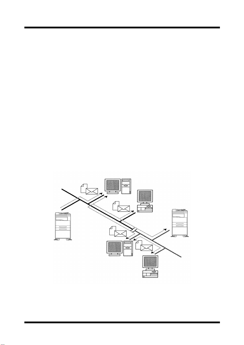
Internet faxing
• As opposed to a normal fax, which transmits t hro ugh telephone lines,
Internet fax sends and receives fax images through the Internet. Internet fax uses the Internet electronic mail (e-mail) setup to send and
receive fax images . Image data scanned at an Inte rnet fax terminal is
attached to an e-mail, then sent to the recipient’s Internet fax terminal.
The file attached to the received e-mail is printed by the Internet fax
terminal on the receiving end.
In addition, since e-mail is us ed, the fa x ca n be se nt to a n individual email address, not just an Internet fax terminal. In this case, the fax
image arrives at the receiving end as an attachment to a mail recei ved
with the usual mail client software.
Mail Server
Client PC
Intranet
Mail Server
Internet Fax
Termi n al
Internet
Client PC
1
1 Introduction
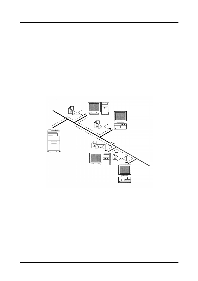
Network scanning
Paper documents can easily be converted to electronic data and used,
for example, with electronic filing.
Scanned image data ( scan da ta) is se nt to a c omputer throu gh a netw ork
as a TIFF-F or PDF file. The scanned image can be sent either as an email attachment or to an FTP server.
• Scan data is sent to a computer as a TI FF-F or PDF fil e att ached to an
e-mail, then sent to a computer through an intranet or the Internet.
(Scan to E-mail)
Mail Server
Client PC
Intranet
Internet
Mail Server
Client PC
2
1 Introduction
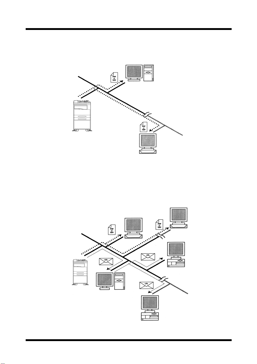
• Scan data is uploaded to an FTP server as a TIFF-F or PDF file.
(Scan to Server)
FTP Server
Intranet
Internet
FTP Server
In addition, the sy stem can be set to s end to a sp ecif ied recipie nt (only
one) a notification of the FTP server address where the data was
uploaded.
Intranet
FTP Server
FTP Server
Internet
Client PC
Internet
Mail Server
Client PC
3

1 Introduction
1.2 Required Environment
The following network environment is required in order to use the Internet
fax and network scanning features.
Internet faxing
• Mail server (POP3 server and SMTP server)
Network scanning (Scan to E-mail)
• Mail server (SMTP server)
Network scanning (Scan to Server)
• FTP server (The enclosed PageScope Cabinet can be used as a sim-
ple FTP server.)
• Mail server (SMTP server) in order to use mail notification
Common
• Ethernet 10/100Base-T
• TCP/IP protocol
1.3 Connecting to a Network (LAN)
In order to use the Internet fax and network scanning features, this machine
must be connected to a LAN and be able to communicate using the TCP/IP
protocol.
Use an Ethernet cable (for 10/100Base-T Ethernet) to connect to the LAN.
(The Ethernet cable is not included with the Internet fax/network scanner.)
IMPORTANT
• Be sure to use a Category 5, shielded cable for the 10/100Base-T
connection, otherwise there may be electronic interference.
4
1 Introduction
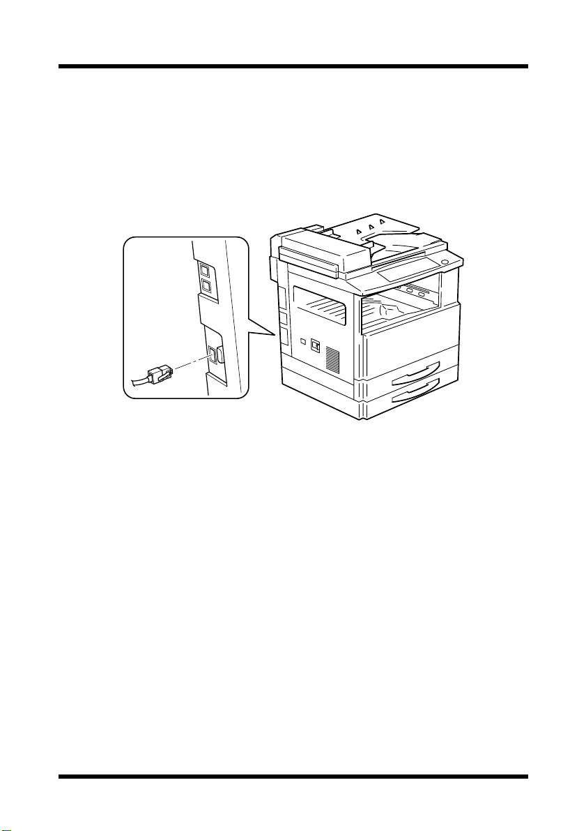
1.3.1 Connecting the Ethernet Cable
1. Make sure that the machine is turn ed off.
2. Insert one plug on the Ethernet cable into the connector (marked “NETWORK SCANNER”) on the left side of the machine, and then insert
the other plug into the hub.
5

1 Introduction
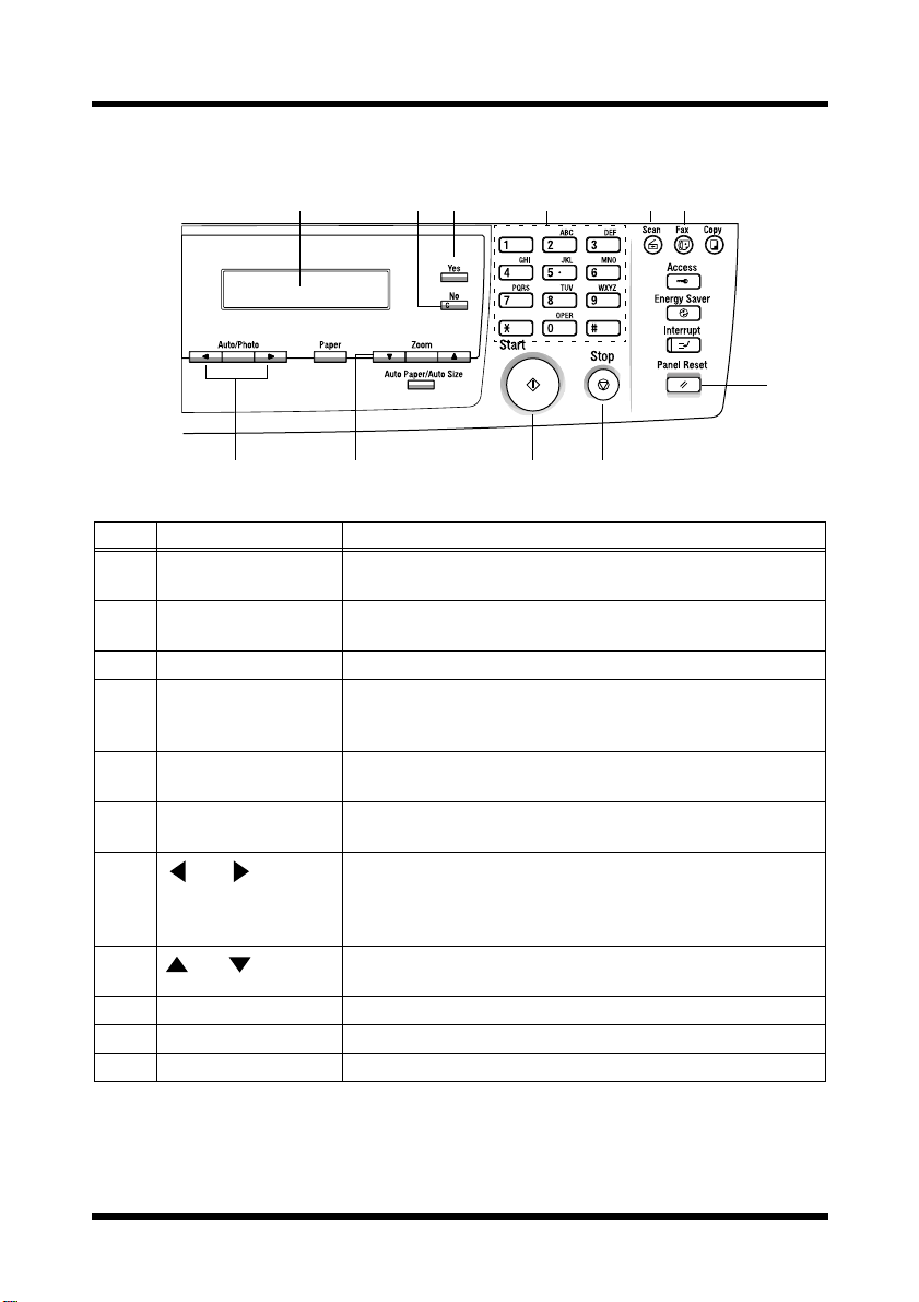
1.4 Control Panel Parts and Their Functions
1.4.1 Names of Control Panel Parts and Their Functions
23 4 567 8
1
9
No. Part Name Function
1 [Error] indicator Lights up if an error has occurred.
2 [Confirm] key Used to view transmission results.
3 [Utility] key Used to display the first Utility mode screen.
4 [Resolution] key Used to select the image quality (transmission resolution)
5 [Phone Book] key Used to display the information programmed for one-touch
6 [Function] key Used to select a function.
7 [Speed Dial] key Used to specify previousl y pr ogrammed fax numbers
8 [Mail] key Press to enter an e-mail address. The key lights up in green
9 One-touch dial keys Used to select previously programmed fax numbers.
MACHINE SETTING, FAX REGISTRATION, E-MAIL
SETTING 1, E-MAIL SETTING 2, NETWORK(FAX/
SCAN)
Refer to “4 Utility Mode Settings” (p. 55).
with the Internet fax feature.
dialing, group dialing and speed dialing.
BROADCAST (broadcast transmission), TIMER T X
(timer transmission), CANCEL RESERV. (cancel queued
job) and INTERNET FAX RX (Internet fax reception) (p.
36, p. 38, p. 39 a nd p. 41)
represented by 3-digit numbers.
to indicate that an e-mail address can be entered.
Used to enter text such as e-mail addresses.
6
1 Introduction
11 12 14 15
1310
20
181716
19
No. Part Name Function
10 Display Displays setting menus, error messages, and specified
settings such as e-mail addresses.
11 [No] key Erases the entered letters and numbers.
Returns to the previous screen.
12 [Yes] key Confirms the current setting.
13 10-key pad Used to enter setting values.
Used to enter numbers.
Used to enter speed dial numbers.
14 [Scan] key Press to enter Scan mode. The key lights up in green to
indicate that the machine is in Scan mode.
15 [Fax] key Used when sending scan data or receiving e-mail with the
Internet fax feature.
16
[Auto/Photo] key
and keys
Used to specify the scanning mode with the Network Scan
feature.
Used to specify the selection at the left or right in setting
screens.
17
and keys
Used to specify the selection above or below in setting
screens and menus.
18 [Start] key Starts scanning or starts sending the e-mail or file.
19 [Stop] key Stops scanning documents.
20 [Panel Reset] key Cancels all current operations.
7
1 Introduction
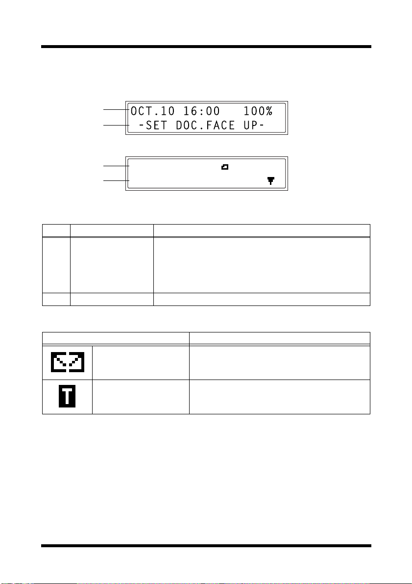
1.4.2 Display Indications
1
2
1
2
No. Display Indication Description
1 Mode or function
name
2 Message area Displays messages such as operating instructions.
SCAN BOOK(LT )
SCAN=YES (SIZE= )
• Displays the currently selected mode or function setting.
• Displays the current menu, function or setting.
• Error messages are displayed when errors occur.
• The current date and remaining amount of memory is
displayed during standby.
Symbol list:
Symbol Description
Sending/receiving mail E-mail is being sent or received.
In standby for timer
transmission
An e-mail is queued for timer transmission.
8

1 Introduction
1.5 Entering Text
When specifying the user name or programming one-touch dial keys with
the recipient name, letters, acc ented characters, numbers and symbols can be
entered.
1.5.1 Key operation:
• One-touch dial keys [01] through [27]: Used to enter letters and sym-
bols.
• 10-Key Pad: Used to enter numbers.
List of characters available with each one-touch dial key:
One-touch dial
key
01 ABC ABC 15 pqr pqr
02 DEF DEF 16 stu stu
03 GHI GHI 17 vwx vwx
04 JKL JKL 18 yz yz
05 MNO MNO 19 @ @
06 PQR PQR 20 . . (period)
07 STU STU 21 _ _ (underscore)
08 VWX VWX 22 + +
09 YZ YZ 23 - - (hyphen)
10 abc abc 24 & &#∗/!=?$%[]’^`{}|˜()”
11 def def 25 ДдЦцЬьбЙйн”ъЕОазЖС¿
12 ghi ghi 26 (space)
13 jkl jkl 27 (deletes)
14 mno mno 28
Available characters*
One-touch dial
key
Available characters*
,:;<>
Øøß
* Repeatedly press the one-touch dial key to scroll through the corresponding char-
acters and symbols listed until the desired character appears in the display.
9
1 Introduction
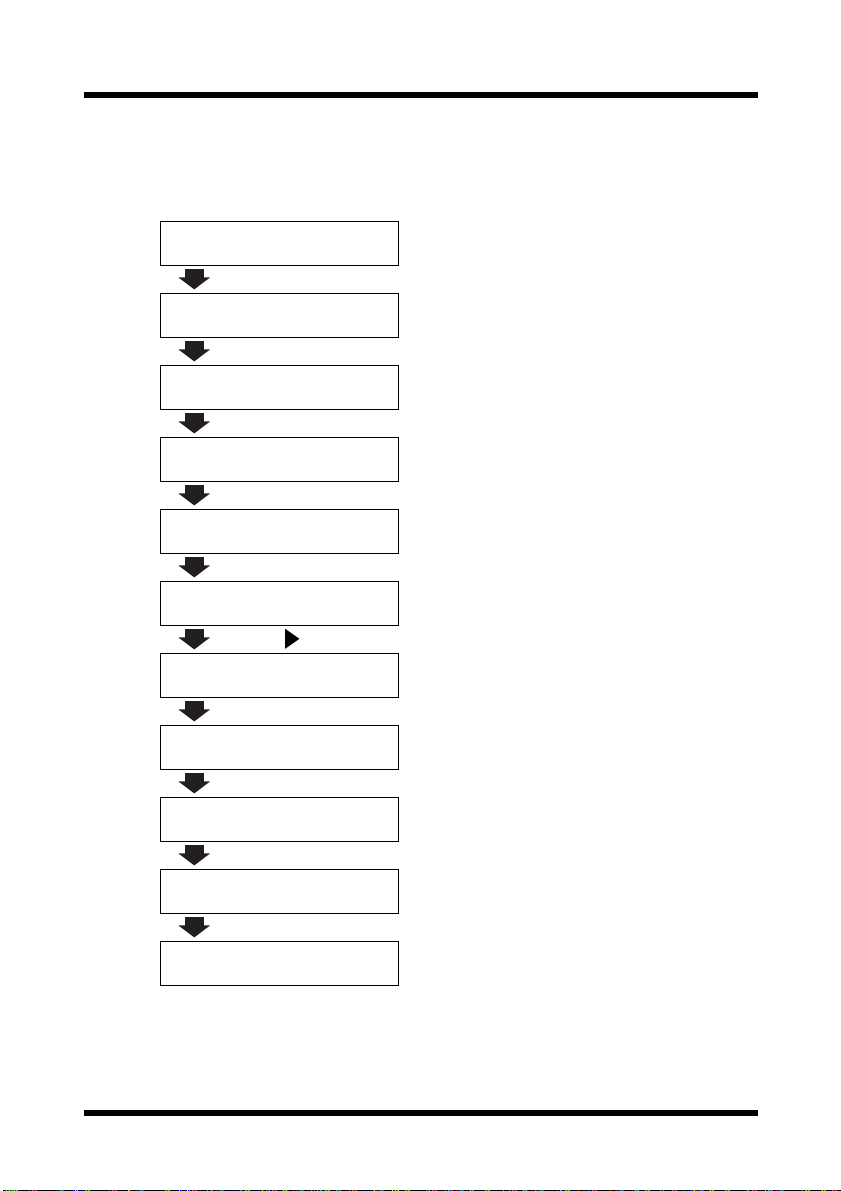
1.5.2 Inputting Example
To enter the name “NJ Office”
* The cursor (_) flashes alternately with the character at its current location.
NAME=_
Press the [MNO] key twice.
NAME=N
Press the [JKL] key once.
NAME=NJ
Press the [Space] key once.
NAME=NJ
Press the [MNO] key 3 times.
NAME=NJ O
Press the [def] key 3 times.
NAME=NJ Of
Press the key.
NAME=NJ Of_
10
Press the [def] key 3 times.
NAME=NJ Off
Press the [ghi] key 3 times.
NAME=NJ Offi
Press the [abc] key 3 times.
NAME=NJ Offic
Press the [def] key twice.
NAME=NJ Office

1 Introduction
Correcting text and input precautions
• To erase all e ntered text, press the [No] key.
• T o de lete onl y part of the en tered te xt, us e the and keys to move
the cursor (_) to the character that you wish to delete, and then press
[Delete] key (one-touch dial key [27]).
the
• To change an entered character, use the and keys to move the
cursor (_) to the charact er that you wi sh t o chan ge, an d then enter the
new characte r. (The character at the cursor’s position is replaced with
the new character.)
• If the same one-touch dial key is needed to enter two characters in a
row, press the key after selecting the first character. (Refer to the
above example.)
• To enter a space, press one-touch dial key
[26].
11

1 Introduction
1.6 Specifying Network Settings
1.6.1 Required Settings
In order to use the Internet fax and network scanning features, certain
settings must first be specified.
Note
• This machine must be set based on the network environment that it is
connected to. Therefore, before starting to set this machine, be sure
to ask the network administrator for the information required to specify
the settings correctly.
Settings Description
❍
: Necessary – : Unnecessary
NETWORK (FAX/SCAN)
IP
ADDRESS
SUBNET
MASK
GATEWAY This function is used t o enter the IP ad dress of the
DNS
CONFIG.
SERVER
TIMEOUT
This function is used to specify the IP address of
the Internet fax/network scanner.
*Obtain from the network administrator.
This function is used to set the subnet mask valu e
of the network.
*Consult with the network administrator.
router, if one is used on the network.
*Consult with the network administrator.
This function is used to enable or disabl e the
DNS (Domain Name System). If a DNS server is
used, specify its IP address.
*If a DNS server is used on the network, select
ENABLE
“
Internet provider is used, select “
”. If an external server such as an
DISABLE
”.
Consult with the network administrator.
This function is used to set the length of time
(between 5 and 20 seconds, in 1 second intervals)
until the connection with the server times out.
E-MAIL SETTING 1
SENDER
NAME
E-MAIL
ADDRESS
This function can be used to speci fy t he sender’s
name.
This function is used to specify the e-mail addres s
of the sender.
*Obtain from the network administrator.
Internet
Faxing
*2
❍
*2
❍
*2
❍
Network
Scanning
(Scan to
E-mail)
●
Network
Scanning
(Scan to
Server)
:As necessary
*2
❍
*2
❍
*2
❍
*2
❍
*2
❍
*2
❍
●●●
❍❍❍
❍❍
❍❍
*1
●
*1
●
12

1 Introduction
Network
Scanning
(Scan to
E-mail)
❍❍
Settings Description
SMTP
SERVER
This function is used to enter the IP address or
host name for the SMTP server.
Internet
Faxing
*Consult with the network administrator.
TEXT
INSERT
This functio n is used to specify whethe r or not to
insert text explaining that an image data has been
❍❍
attached when scan data attac hed to an e-mail is
being sent.
DEFAULT
SUBJECT
TIME ZONE This function is used to set the time zone
This function can b e us ed to s et th e def ault su bj ect
used when sendin g scan data att ach ed to an e- mai l.
❍❍
❍❍
corresponding to the country where the machine
is being used. For the Un ited S ta te s, the time will
appear as “GMT -05:00”.
E-MAIL SETTING 2
POP3
SERVER
POP3
ACCOUNT
POP3
PASSWORD
AUTO
RECEPTION
REPLY
ADDRESS
HEADER
PRINT
*1: Necessary if notification of the URL is sent by e-mail.
*2: May also be assigned aut omatically by the DHCP server.
This function is used to enter the IP address or
host name for the POP3 server.
*Consult with the network administrator.
This function is used to specify the account name
used to log into the POP3 server.
*Consult with the network administrator.
This function is used to specify the p assword used
to log into the POP3 server.
*Consult with the network administrator.
This function is used to specify the time interval
(between 1 and 60 minutes, in 1 minute intervals)
for checking for new e-mail during automatic
reception.
This function is used to specify the recipient of
error notification e-mails if an error occurs while
receiving an Internet fax.
This functio n is used to specify whethe r or not to
print header information of “subject”, “from”,
and “cc” when printing e-mails.
❍
❍
❍
❍
❍
❍
––
––
––
––
––
––
Tip
• After specifying the IP address, subnet mask and gateway functions
on the “NETWORK(FAX/SCAN)” menu, other settings can be
specified using PageScope Light. For details, refer to the PageScope
Light for Di152f/Di183f Scanner User Manual.
Network
Scanning
(Scan to
Server)
*1
●
*1
●
*1
●
*1
●
13
1 Introduction
1.6.2 Specifying Network Settings (“NETWORK(FAX/
SCAN)” Menu)
From the “NETWORK(FAX/SCAN)” menu of the Utility mode, various
network settings can be specified.
Tip
• If, at any time, you wish to quit setting a “NETWORK(FAX/SCAN)”
function, press the [No] key. When the message “STOP SETTING?”
appears, press the [Yes] key to quit.
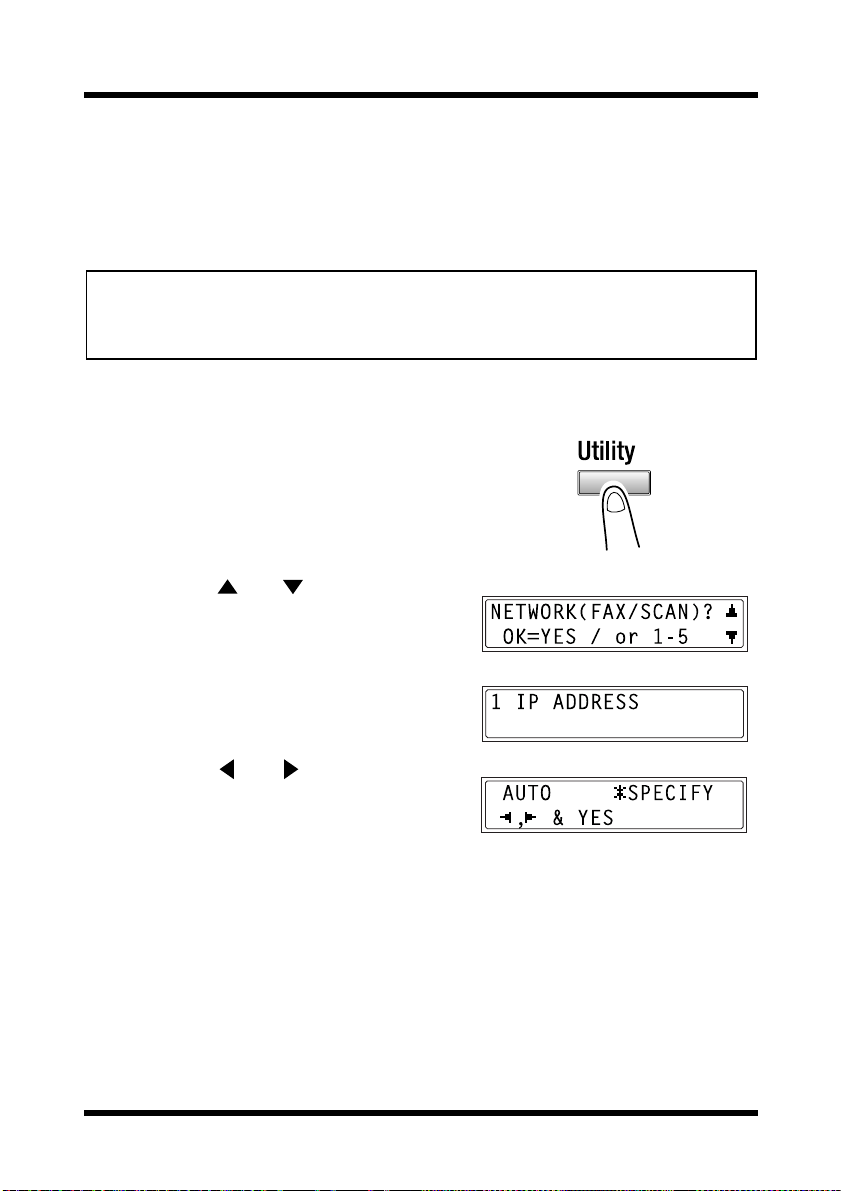
To set the “IP ADDRESS” function
1. Press the [Utility] key.
The first scree n of the Utility mode
appears.
2. Using the and keys, select
NETWORK(FAX/SCAN)”.
“
3. Press the
to select “
[1] key from the 10-key pad
IP ADDRESS”.
4. Using the and keys, select ei ther
AUTO” or “SPECIFY”, and then
“
press the
•If “
[Yes] key.
AUTO” was selected so the IP
address will automatically be
assigned by the DHCP server, the
NETWORK(FAX/SCAN)” menu
“
appears again.
SPECIFY” was selected, a screen
•If “
appears, allowing you to specify the
IP address. (Continue with step 5.)
14
1 Introduction
Note
• “AUTO” is available if a DHCP server is on the network. If “AUTO”
is selected, it will not be necessary to specify the subnet mask or
gateway settings.
• If a fixed IP address has been set, you must select “IP Address in
NVRAM” in the enclosed PageScope Light. Make this setting in
the “TCP/IP Configuration” menu on the “Network” tab. For more
details, refer to the PageScope Light for Di152f/Di183f Scanner
User Manual.
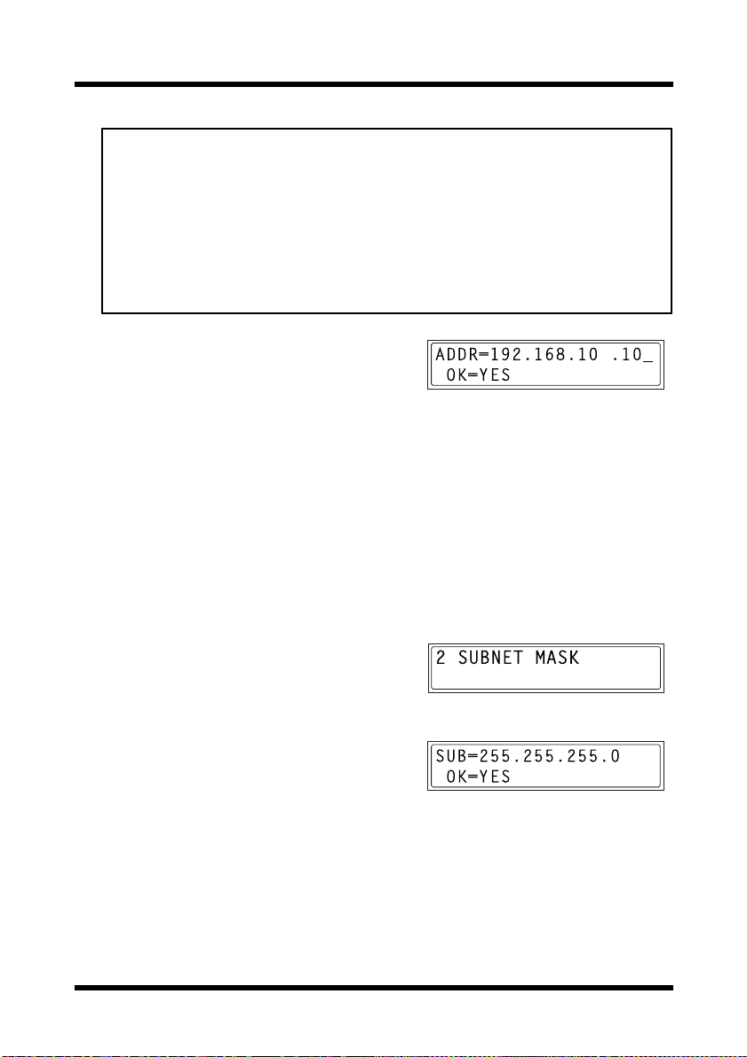
5. Using the 10-key pad, enter the IP
address of the Internet fax/network
scanner.
• The screen at the right shows an
example of an entered IP address.
For the appropriate set ti ng, cons ul t
the network administrator.
6. Press the
The “
[Yes] key.
NETWORK(FAX/SCAN)”
menu appears again.
To set the “SUBNET MASK” function
1. From the “NETWORK(FAX/SCAN)”
menu of the Utility mode, press the
[2]
key from the 10-key pad to select
SUBNET MASK”.
“
2. Using the 10-key pad, enter the subnet
mask value.
• The screen at the right shows an
example of an entered subnet mask.
For the appropriate set ti ng, cons ul t
the network administrator.
3. Press the
The “
[Yes] key.
NETWORK(FAX/SCAN)”
menu appears again.
15
1 Introduction
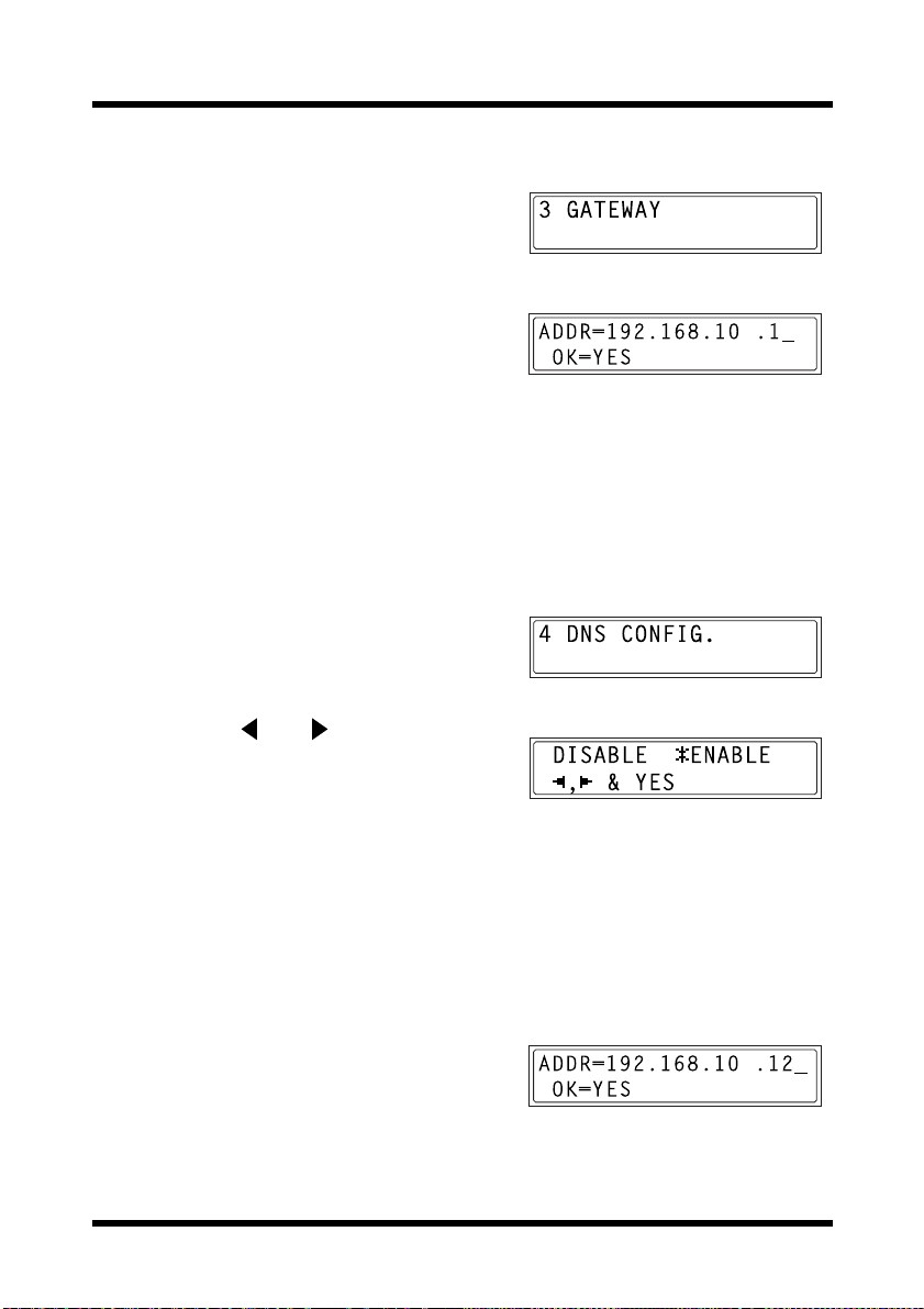
To set the “GATEWAY” function
1. From the “NETWORK(FAX/SCAN)”
menu of the Utility mode, press the
key from the 10-key pad to select
GATEWAY”.
“
2. Using the 10-key pad, enter the IP
address of the gate w ay.
• The screen at the right shows an
example of an entered IP address.
For the appropriate set ti ng, cons ul t
the network administrator.
[3]
3. Press the
The “
To set the “DNS CONFIG.” function
[Yes] key.
NETWORK(FAX/SCAN)” menu appears again.
1. From the “NETWORK(FAX/SCAN)”
menu of the Utility mode, press the
[4]
key from the 10-key pad to select
DNS CONF IG.”.
“
2. Using the and keys, select ei ther
DISABLE” or “ENABLE”, and then
“
press the
•If “
“
[Yes] key.
DISABLE” was selected, the
NETWORK(FAX/SCAN)” menu
appears again.
ENABLE” was selected, a screen
•If “
appears, allowing you to specify the
IP address of the DNS server. (Continue with step 3.)
3. Using the 10-key pad, enter the IP
address of the DNS server.
4. Press the
The “
[Yes] key.
NETWORK(FAX/SCAN)”
menu appears again.
16
 Loading...