

Konica Minolta DI152F, PI1802E PAGESCOPE LIGHT, DI152, DI183, DI183F FAX UNIT FX-1 User Manual
Page 1

7664-4968-02
This version available on ParnterLink Only. Not available to order in hard copy.
User Manual
Printer Controller Pi1802e
Page 2

Foreword
Trademark Acknow ledg emen ts
Minolta is a registered trademark of MINOLTA CO., LTD.
PageScope is a trademark of MINOLTA CO., LTD.
Ethernet is a registered trademark of Xerox Corporation.
Microsoft, Windows, and Windows NT are either registered trademarks or
trademarks of Microsoft Corporation in the United States and/or other
countries.
Netscape and the Netscape N and Ship’s Wheel logos are regi stered
trademarks of Netscape Communications Corporation in the U.S. and other
countries. Netscape Navigator is also a trademark of Net scape
Communications Corporation and may be registered outside the U.S.
Novell and NetWare are registered trademarks of Novell, Inc.
PCL is a registered trademark of Hewlett-Packard Company Limited.
All other product names are trademarks or registered trademarks of their
respective holders.
Copyright 2001 MINOLTA CO., LTD.
Screen images shown in this manual may differ slightly from actual
ones. Specifications are subject to change without prior notice.
i
Page 3

For the U.S.A. Users
FCC Part 15-Radio Frequency Devices
This device complies with Part 15 of the FCC Rules. Operation is subject to the
follo wing tw o condi tions: (1) This de vi ce ma y no t cause harmful interf ace , and (2 )
this device must accept any interface received, including interface that may
cause undesired operation.
NOTE: Thi s eq uip me nt ha s been tested and found to comply wit h the lim its for a
Class A digital device, pursuant to Part 15 of the FCC Rules. These limits are
designed to pro vide reas onab le pr otection aga inst harmful in terf erenc e when the
equipment is operated in a commercial environme nt. Thi s e qui pm ent generates,
uses, and can radiate radio frequency energy and if not installed and used in
accordance with the instruction manual, may cause harmful interference to radio
communications.
Operation of this equipment in a residential area is likely to cause harmful interference in which case the user will be required to correct the interference at his
own expense.
WARNING: The design and production of this unit conform to FCC Regulations,
and any changes or modifications must be registered with the FCC and are subject to FCC control. Any changes made by purchaser or user without first contacting the manufacturer will be subject to penalty under FCC regulations.
This device must be used with shielded interface cables. The use of nonshielded cab les is lik ely to result in int erfere nce with radi o communi cations and is
prohibited under FCC rules.
For Cana da Users
Interference-Causing Equipment Standard (ICES-003 Issue 3)
This Class A digital apparatus complies with Canadian ICES-003.
Cet appareil numerique de la classe A est conforme a la norme NMB-003 du
Canada.
ii
Page 4
For Europe
CE Marking (Declaration of Conformity)
This product complies with the following EU directives:
89/336/EEC, 73/23/EEC and 93/68/EEC directives.
This declaration is valid for the area of the European Union.
This device must be used with shielded interface cables. The use of nonshielded cab les is lik ely to result in int erfere nce with radi o communi cations and is
prohibited under EU directives.
For Users of the Class B regulation’s countries
This device must be used with shielded interface cables. The use of nonshielded cab les is lik ely to result in int erfere nce with radi o communi cations and is
prohibited under CISPR 22 rules and local rules.
For Users except the Class B regulation’s countries
W ARNING
This is a Class A product. In a domestic environment this product may cause
radio interference in which case the user m ay be required to take ade qua te me asures.
This device must be used with shielded interface cables. The use of nonshielded cab les is lik ely to result in int erfere nce with radi o communi cations and is
prohibited under CISPR 22 rules and local rules.
iii
Page 5

Contents
CONTENTS
1 Getting Ready .................................................... 1
1.1 System Requirements ............................................. 1
2 Connecting to a Computer ............................... 2
2.1 Connecting to the Parallel Port
(Local Connection) ..................................................3
2.2 Connecting to the Ethernet 10/100Base-T Port
(Network Connection) .......................... ..... ..... .... .....4
3 Installing the Printer Driver .............................. 5
3.1 Windows 95/98/Me ................................................... 5
3.2 Windows NT 4.0 .......................................................7
3.3 Windows 2000 .......................................................... 9
3.4 Uninstalling the Printer Driver ..............................11
4 Printer Driver Settings .................................... 12
4.1 Displaying the Printer Driver Setup Dialog .........12
4.2 Common Settings ............................................... ...13
4.3 Setup Tab ................................................................14
4.3.1 N-up ............................................................... 15
4.3.2 Watermark ..................................................... 16
4.3.3 Paper Source ................................................18
iv
Page 6

Contents
4.4 Paper Tab ................................................................19
4.4.1 Original Document Size ...............................19
4.4.2 Output Paper Size ................................. ....... 21
4.4.3 Copies ........................................................... 22
4.4.4 Collate at Printer .......................................... 22
4.4.5 Orientation .................................................... 22
4.5 Quality ..................................................................... 23
4.5.1 Resolution ..................................................... 23
4.5.2 Toner Save ....................................................23
4.5.3 Rendering Mode ........................................... 23
4.5.4 Font Setting ................................. ..... ..... ....... 24
4.5.5 Image Adjustment ........................................24
4.6 Device Option Tab ..................................................25
5 Digital Copier Control Panel Operations
(PC Print Mode) .... .. ... ...................................... 26
5.1 Operation Using the Di152/Di183 ...................... ...26
5.1.1 Names of Control Panel Parts and
Their Functions ............................................ 27
5.1.2 [Printer] Indicator/[Start] Key ......................28
5.1.3 Cancelling a Print Job .................................28
5.1.4 Using Manual Bypass Tray ..........................29
5.1.5 Outputting a Report ..................................... 30
v
Page 7

Contents
5.2 Operation Using the Di152f/Di183f ................ .... ...32
5.2.1 Names of Control Panel Parts and
Their Functions ............................................ 33
5.2.2 [Printer] Indicator/[Start] Key ......................34
5.2.3 Switching to PC Print Mode ........................34
5.2.4 Cancelling a Print Job .................................35
5.2.5 Using Manual Bypass Tray ..........................36
5.2.6 Outputting a Report ..................................... 37
6 Digital Copier Settings for Use on a Netw ork .. 39
6.1 Specifying Settings Using the Di152/Di183 ......... 40
6.1.1 IP Address ............................................. .... ...40
6.1.2 Entering Values ............................................41
6.1.3 Subnet Mask ................................................. 42
6.1.4 Gateway ......................................................... 42
6.1.5 Restarting the Digital Copier ......................43
6.2 Specifying Settings Using the Di152f/Di183f ...... 44
6.2.1 IP Address ............................................. .... ...44
6.2.2 Subnet Mask ................................................. 45
6.2.3 Default Gateway ........................................... 46
6.2.4 Restarting the Digital Copier ......................46
vi
Page 8

Contents
7 Network Printing in a Windows Environment .. 47
7.1 Peer-to-Peer Printing (Windows 95/98/Me) ..........47
7.1.1 Before You Begin .........................................47
7.1.2 Settings for Windows 95/98/Me ................... 47
7.2 LPR Printing (Windows NT 4.0/2000) ...................49
7.2.1 Before You Begin .........................................49
7.2.2 Settings for Wi ndows NT 4.0 .......................49
7.2.3 Settings for Windows 2000 ..........................50
7.3 IPP Printing (Windows 2000) ................................ 52
7.3.1 Before You Begin .........................................52
7.3.2 Installing the Printer Driver .........................52
7.4 Printing via a NetWare Server ...............................53
7.4.1 Before You Begin .........................................53
7.4.2 Settings for Windows 95/98/Me ................... 54
7.4.3 Settings for Windows NT 4.0/2000 ..............55
8 Troubleshooting ............. ... .. ...................... .. ... .. 56
8.1 Correcting Errors for the Di152/Di183 ..................56
8.1.1 Main Error Messages ................................... 56
8.2 Correcting Errors for the Di152f/Di183f ...............58
8.2.1 Checki ng Error Messages ...........................58
8.2.2 Main Error Messages ................................... 59
vii
Page 9

Contents
9 Appendix .......................................................... 60
9.1 Assigning IP Parameters Using Initializer ........... 60
9.1.1 Using Initializer .............................................60
9.2 Specifications ........................................................ 62
viii
Page 10

1 Getting Ready
1 Getting Ready
1.1 System Requirements
Operating System
• Microsoft Windows 95
• Microsoft Windows 98
• Microsoft Windows Me
• Microsoft Windows NT Workstation Version 4. 0
• Microsoft Windows 2000
When the ne twork interface card is installed, th e printer controller will run
in the following environment.
Client operating system Windows 95/98/Me/NT 4.0/2000
Network interface type Ethernet 10/100Base-T
Network protocol TCP/IP, IPX/SPX
1
Page 11

2 Connecting to a Computer
2 Connecting to a Computer
Connect the printer controller to the computer using either of the following
two methods.
To connect to the parallel port
Using a parallel cable, local ly connect the printer directly to a
computer.
Refer to “2.1 Connecting to the Parallel Port (Local Connection)” on
page 3.
To connect to the Ethernet 10/100Base-T port
If the printer is to be used on a network, connect it using a 10/100BaseT cable.
Refer to “2.2 Connecting to the Ethernet 10/100Base-T Port (Network
Connection)” on page 4.
Important!
• If the printer is to be used on a network, the optional network
interface card NC-3 must be installed.
2
Page 12
2 Connecting to a Computer
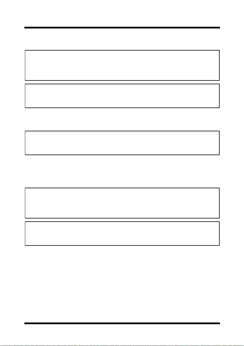
2.1 Connecting to the Parallel Por t (Local Connection)
Use the parallel cable to connect the parallel port of the printer controller to
the parallel port of the computer.
Important!
• Be sure to use a shielded parallel cable. Use of an unshielded cable
may result in radio frequency interference.
• The parallel port is compatible with IEEE1284 Type B standards.
1. Make sure that the Digital Copier and the computer to be connected to
the Digital Copier are turned OFF.
2. Connect one end of the parallel cable to the parallel port (printer port)
of the computer.
3. Connect the other end of the c able to the parallel port of the printer controller installed in the Dig i tal Copier.
This comple tes the connection of the printer controller to the computer.
3
Page 13
2 Connecting to a Computer
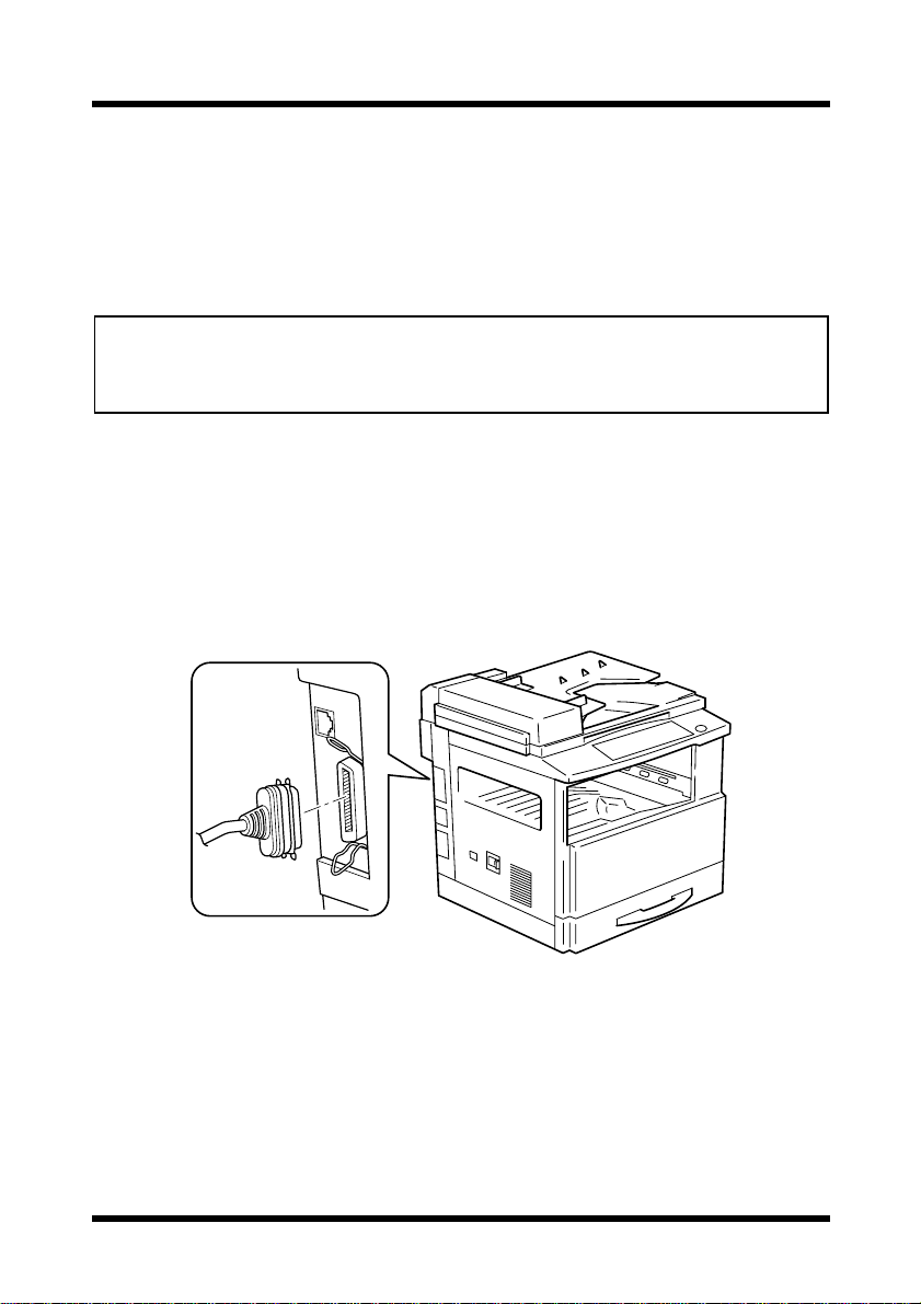
2.2 Connecting to the Ethernet 10/100Base-T P ort
(Network Connection)
If the printer is to be used on a network, connect the network interface card
to the network (LAN).
Important!
• This connection requires the optional network interface card NC-3.
• Be sure to use a shielded cable for the Ethernet 10/100Base-T cable.
Use of an unshielded cable may result in radio frequency interference.
1. Make sure that the Digital Copier is turned OFF.
2. Connect one end of the Ethernet 10/100Base-T cable to the 10/
100Base-T port of the network interface card, and then connect the
other end of the cable to the hub.
This completes the network connection.
4
Page 14
3 Installing the Printer Driver
3 Installing the Printer Driver
This section explains the procedure for installing the printer driver in the
CD-ROM that comes with the printer controller.
The installation procedure differs according to the computer’s operating
system. See the page indicated below for the installation procedure
corresponding to your computer’s operating system.
• “3.1 Windows 95/98/Me” on page 5
• “3.2 Windows NT 4.0” on page 7
• “3.3 Windows 2000” on page 9
3.1 Windows 95/98/Me
1. Turn on the Digital Copier.
2. Turn on your computer and start up Windows 95, 98 or Me.
3. Insert the CD-ROM that comes with your pr inter controller into your
computer’s CD-ROM drive.
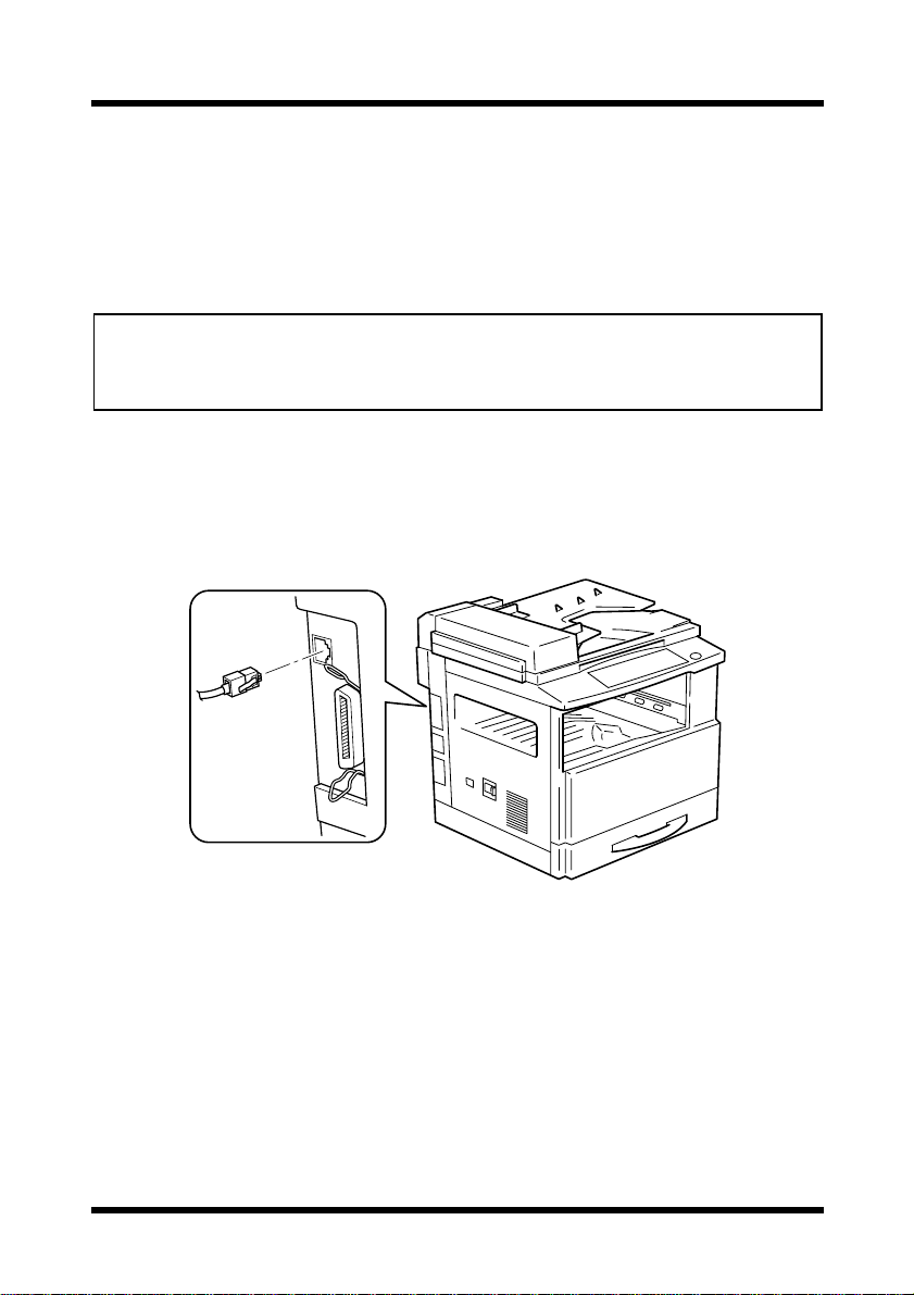
4. Click the
5. Double-click the “
6. Click the
7. Select “
[Start] button, point to [Settings], and then click [Printers].
[Next] button.
Local printer”.
Add Printer” icon.
5
Page 15
3 Installing the Printer Driver
Note
• For details on specifying network settings, refer to “7 Network
Printing in a Windows Environment” on page 47. Since other
network settings must first be specified, temporarily install the
printer driver under a local connection.
• For the network printer settings, consult with the network
administrator.
8. Click the
9. Click the
10. Click the
[Next] button.
[Have Disk] button.
[Browse] button.
11. Specify the printer driver directory on the CD-ROM for the environment being used, and then click the
[OK] button. (Example: CD-ROM
drive\English\Win 98\PCL6\)
Then click the
12. Click the
13. Click the
[OK] button.
[OK] button.
[Next] button.
14. Specify the port (LPT1, 2, etc.) where the printer controller is connected.
15. Follow the instructions that appear on your computer screen to complete the installation.
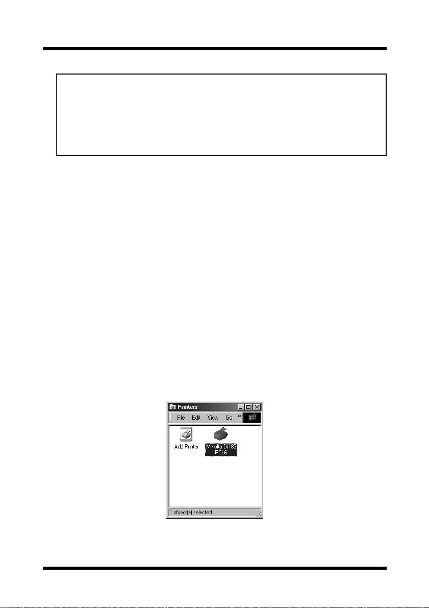
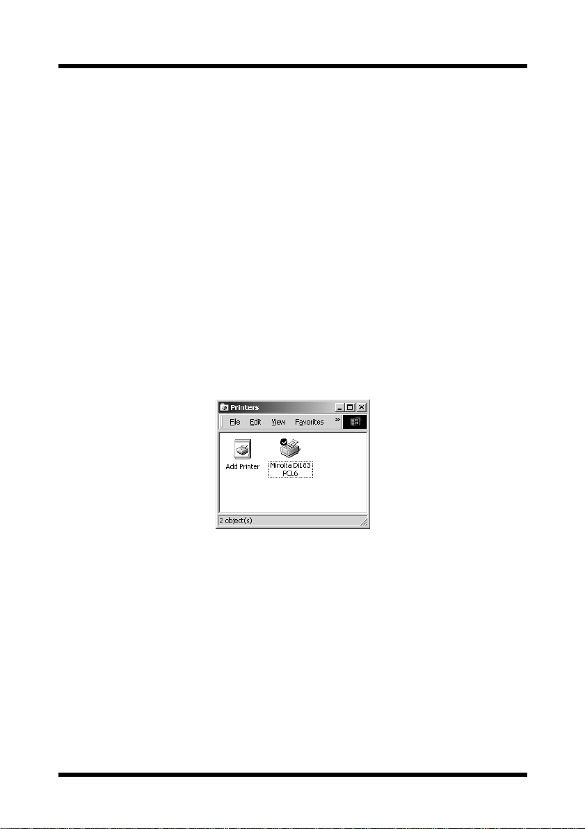
16. After installation is complete, check that the icon for the installed
printer appears in the “
Printers” win dow.
17. Eject the CD-ROM from your computer’s CD-ROM drive.
This completes the install ation of the printer driver.
6
Page 16
3 Installing the Printer Driver
3.2 Windows NT 4.0
Note
• When installing the printer driver on Windows NT 4.0, be sure to log in
with Power User or higher-level privileges.
1. Turn on the Digital Copier.
2. Turn on your computer and start up Windows NT 4.0.
3. Insert the CD-ROM that comes with your pr inter controller into your
computer’s CD-ROM drive.
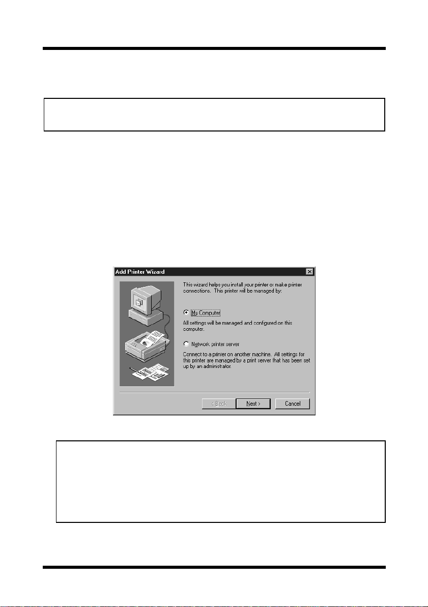
4. Click the
5. Double-click the “
6. Select “
[Start] button, point to [Settings], and then click [Printers].
Add Printer” icon.
My Computer”.
Note
• For details on specifying network settings, refer to “7 Network
Printing in a Windows Environment” on page 47. Since other
network settings must first be specified, temporarily install the
printer driver under a local connection.
• For the network printer settings, consult with the network
administrator.
7. Specify the port (LPT1, 2, etc.) where the printer controller is connected.
7
Page 17
3 Installing the Printer Driver
8. Click the [Next] button.
9. Click the
10. Click the
[Have Disk] button.
[Browse] button.
11. Specify the printer driver directory on the CD-ROM for the environment being used, and then click the
[OK] button. (Example: CD-ROM
drive\English\Win NT\PCL6\)
Then click the
12. Click the
[OK] button.
[OK] button.
13. Follow the instructions that appear on your computer screen to complete the installation.
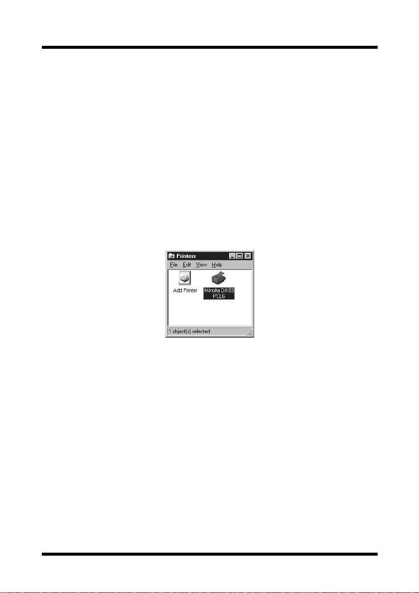
14. After installation is complete, check that the icon for the installed
printer appears in the “
Printers” win dow.
15. Eject the CD-ROM from your computer’s CD-ROM drive.
This completes the install ation of the printer driver.
8
Page 18
3 Installing the Printer Driver
3.3 Windows 2000
Note
• When installing the printer driver on Windows 2000, be sure to log in
with Power User or higher-level privileges.
1. Turn on the Digital Copier.
2. Turn on your computer and start up Windows 2000.
3. Insert the CD-ROM that comes with your pr inter controller into your
computer’s CD-ROM drive.
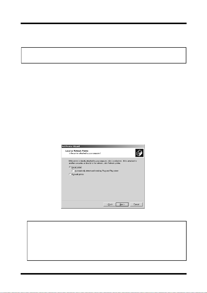
4. Click the
5. Double-click the “
6. Click the
7. Select “
install my Plug and Play printer
[Start] button, point to [Settings], and then click [Printers].
Add Printer” icon.
[Next] button.
Local printer”. (Do not check the “Automatically detect and
” box.)
Note
• For details on specifying network settings, refer to “7 Network
Printing in a Windows Environment” on page 47. Since other
network settings must first be specified, temporarily install the
printer driver under a local connection.
• For the network printer settings, consult with the network
administrator.
9
Page 19
3 Installing the Printer Driver
8. Specify the port (LPT1, 2, etc.) where the printer controller is connected.
9. Click the
10. Click the
11. Click the
[Next] button.
[Have Disk] button.
[Browse] button.
12. Specify the printer driver directory on the CD-ROM for the environment being used, and then click the
[OK] button. (Example: CD-ROM
drive\English\Win NT\PCL6\)
Then click the
13. Click the
[OK] button.
[OK] button.
14. Follow the instructions that appear on your computer screen to complete the installation.
15. After installation is complete, check that the icon for the installed
printer appears in the “
Printers” win dow.
16. Eject the CD-ROM from your computer’s CD-ROM drive.
This completes the install ation of the printer driver.
10
Page 20
3 Installing the Printer Driver
3.4 Uninstalling the Printer Driver
If it is necessary to delete the printer driver, for example, to re-install it,
follow the procedure described below.
1. Click the
2. In the “
[Start] button, point to [Settings], and then click [Printers].
Printers” window, click the “Minolta Di152 (Di183) PCL6”
printer icon.
3. Select “
Delete” from the “File” menu.
4. Follow the instructions that appear on your computer screen to complete the uninstallation.
For Windows 2000, follow the procedure below.
For Windows 2000:
1. Click the [Start] button, point to [Settings], and then click [Printers].
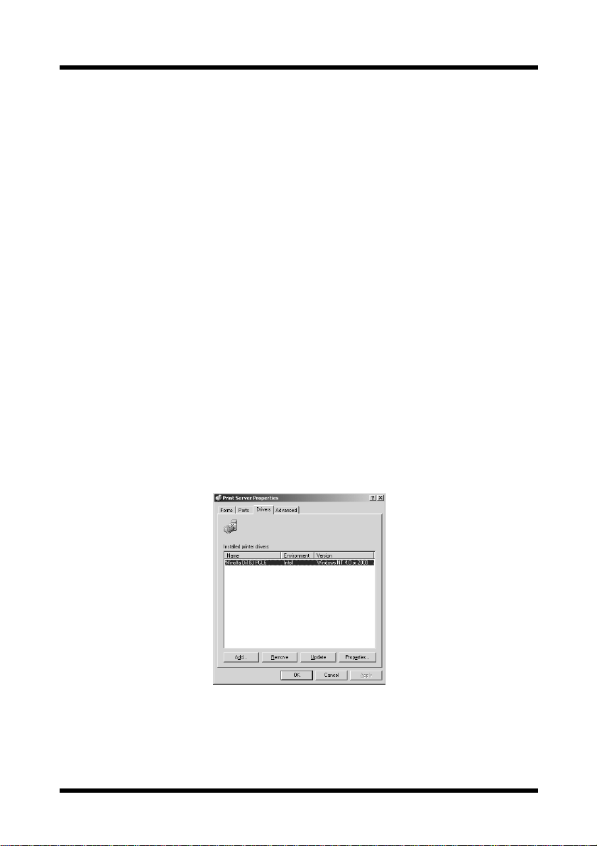
2. With no printer selec ted in the “
erties
” from the “File” menu.
3. Display the
4. Select “
[Drivers] tab on the Print Server Properties dialog box.
Minolta Di152 (Di183) PCL6”, and then click the [Remove] but-
Printers” window, select “Server Prop-
ton.
11
Page 21
4 Printer Driver Settings
4 Printer Driver Settings
From the printer dri v er setup dialog, v a rious pri nter setti ngs can be sp ecif ied
from the computer. The procedure for displaying this dialog and for
specifying the various settings in this dialog is described below.
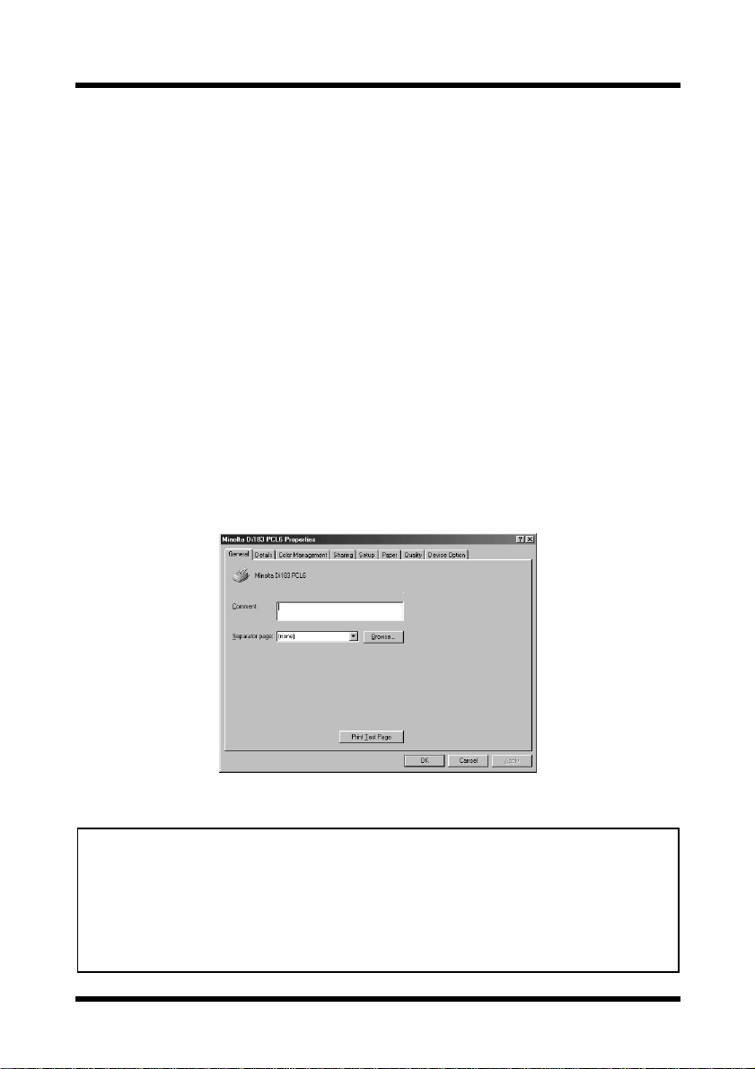
4.1 Displaying the Printer Driver Setup Dialog
1. Click the [Start] button, point to [Settings], and then click [Printers].
2. In the “
printer icon.
3. For Windows 95, 98 or Me, select “
For Windows NT 4.0, select “
menu.
For Windows 2000, select “
Tip
• The tabs other than four rightmost tabs of this dialog differ according
to the computer’s operating system. With Windows NT 4.0 and 2000,
these tabs do not appear.
• These four rightmost tabs can be viewed if the setup dialog is
displayed by clicking the [Properties] button in the application’s print
dialog.
Printers” window, click the “Minolta Di152 (Di183) PCL6”
Properties” from the “File” menu.
Documents Defaults” from the “File”
Printing Preference” from the “File” menu.
The following printer driver setup dialog appears.
12
Page 22
4 Printer Driver Settings
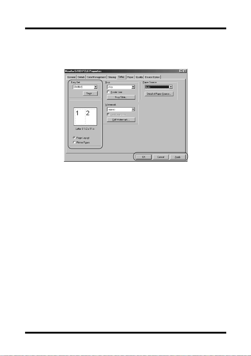
4.2 Common Settings
This section contains descr iptions of the set tings common to all the fou r tabs
(
[Setup], [Paper], [Quality], and [Device O ption]).
OK
Click to exit the Properties dialog box, saving any changes made.
Cancel
Click to exit the Properties dialog box without saving any changes
made.
Apply
Click to save all changes without exiting the Properties di alog box.
Easy Set
To save the current settings, click the [Save] button. Afte rward, the
saved settings can be selected from the drop-down list.
Select “
Factory’s Defaults” from the drop-down list to reset the
functions of the tab to their original values.
If a setting is selected fr om the drop-do wn list, the b utton change s to the
[Delete] button. If the [Delete] button is clicked, the selected setting is
deleted.
13
Page 23

4 Printer Driver Settings
Page Layout/Printer Figure
If “Page Layout” is selected, a sample of the page layout is displayed.
This allows you to check the paper size, and “
settings.
If “
Printer Figure” is selected, a diagram of the printer construction is
displayed. All inst alled options are displayed, and the tray currently
selected under “
selected) appears in light blue.
Paper Source” on the [Setup] tab (all trays if “Auto” is
N-up” and “Watermark”
4.3 Setup Tab
The [Setup] tab conta ins sett ings con cerning the N-up, Watermark and paper
source settings.
14
Page 24

4 Printer Driver Settings
4.3.1 N-up
Note
“N-up” cannot be set under the following conditions:
• When the “Output Paper Size” option on the [Paper] tab is checked
• When the “Scaling” setting on the [Paper] tab is specified
• When “Rendering Mode” on the [Quality] tab is set to “Send Page
as Raster”
From the drop-do wn l ist, s elect the number of page s to be printe d on a s ingle
sheet of paper. For example, if “
divided in half so that two pages can be printed on it. If “
only one page is printed on a single sheet of paper.
Border Line
Check this option to print a border around each page when multiple
pages are printed on a single sheet of paper.
N-up Style
If this button is clicked, the following dialog appears.
2-up” is selected, one sheet of paper is
Off” is selected,
When multiple pages are printed on a single sheet of paper, the
orientation and order for printing the pages can be set. Refer to the
diagrams and select the desired setting.
15
Page 25

4 Printer Driver Settings
4.3.2 Watermark
You can place watermarks on a document to quickly alert the reader to the
nature of its content. F or example: CONFIDENTIAL, DRAFT, etc. Select a
watermark you wish to use in the drop-down list.
First Page Only
A watermark can be specified to appear on the first page only of a
multi-page document by checking this option. Otherwise, a watermark
that is specified to appear will be placed on every page of the multipage document.
Edit Watermark
Click this button to open the Watermark Settings dialog.
When editing a watermark, select the watermark in the “
Watermark
” list, and then make various settings. In addition, double-
Select a
click a watermark in the list to change the watermark string.
New
To create a new watermark, click the [New] button. A dialog t hat a ll ows
you to type in the text for the watermark appears. Type in the watermark
text that you wis h to be pri nted on th e pa per. The text for t he w ate rmark
can only contain 31 characters. In addition, a maximum of 32 different
watermarks can be specified.
16
Page 26

4 Printer Driver Settings
Delete
To remove a watermark, select the watermark that you wish to remove
from the list, click the
Font
To specify the font for a watermark, select the watermark from the
drop-down list, and then click the
appears.
[Delete] button.
[Font] button. The Font dialog
Font:
Fon t style:
Size:
Script:
Sample:
Angle
The font of the watermark is specified here.
The font style of the watermark is specified here.
Select or type in the font size of the watermark (between 20
and 200 points).
Select the type of the Symbol set.
A sample of the specified settings can be viewed here.
The angle at which the watermark is printed on the paper can be set
between -180° and +180°.
Darkness
The density at which the watermark is printed can be set between -10
and +10.
17
Page 27

4 Printer Driver Settings
X-Offset/Y-Offset
Move the scroll box to the desired horizontal/vertical location to adjust
the position of the watermark in the document.
Check “
Automatic Center to Page” to print the watermark in the center
of the document.
Default
Click this button to return settings to their initial factory defaults.
4.3.3 Paper Source
The Paper Sou rce item specifies the tray from which paper is fed from the
Digital Copier. Select the desired paper source (and media type) from the
drop-down list.
If “
Auto” is selected, the tray containing the paper of the specified size is
automatically selected.
If “
Tray1” or “Bypass” is selected, the paper type (plain paper, thick paper,
or OHP) can also be specified .
Note
• If the desired tray is an option and does not appear as a paper
source, make sure that it has been added in the [Device Option] tab.
Detail of Paper Sour ce
If the first or last page is to be su pplied from a tray different from the
tray supplying pa per fo r the rest of the document, click thi s button. The
Detail Of Paper Source dialog appears.
18
Page 28

4 Printer Driver Settings
Front Cover Page
Check this option when print ing the f i rst pag e on paper from a different
paper tray.
Back Cover Page
Check this option when printing the last page on pape r fr om a different
paper tray.
With Image
Check this option to print the front/back cover page.
Cover Paper Source
Select the paper tray for printing the specified front/back cover page.
4.4 Paper Tab
The [Paper] tab contains functions that effect the output of your printed
documents.
4.4.1 Original Document Size
The variou s sizes of paper that are suppo rted by your pri nter are dis played i n
the drop-down list. Select the document size.
19
Page 29

4 Printer Driver Settings
Edit Custom
Click this button to add a paper size to the “Original Document Size”
drop-down list or to change an existing custom paper size. The dialog
that allows you to specify custom paper sizes appears.
New
To add a custom paper size, click the [New] button.
Edit
To change a custom paper size that has already been defined, select the
desired paper name, and then click the
Delete
To delete a custom paper size from the list, select the desired paper
name, and then click the
[Delete] button.
[Edit] button.
When the
[New] or [Edit] button is clicked, additional settings appear at
the bottom of the dialog.
20
Page 30

4 Printer Driver Settings
Enter the name of the custom siz e into the “Name” box (maximum 40
characters). Next, specify either “
the dimensions for “
Width” and “Hei gh t”. Click the [OK] button at the
inch” or “mm” in “Unit”, then enter
bottom of the dialog. The custom size will be added to the above list.
Note
• The paper width can be set between 3.54 and 11.69 inches (90 and
297 mm), and the length can be set between 5.51 and 17.00 inches
(140 and 432 mm).
• Be sure that the setting for the “Height” is longer than the setting for
the “Width”.
• When using a custom size specified with the printer driver, be sure to
set that size first with the Digital Copier.
• If “Auto” is selected under “P aper Source” on the [Setup] tab, the
custom size cannot be used.
4.4.2 Output Paper Size
Note
No setting under “Output Paper Size” can be specified under the
following conditions:
• When the “N-up” setting on the [Setup] tab is specified to print
multiple pages on a single sheet of paper
• When “Rendering Mode” on the [Quality] tab is set to “Send Page as
Raster”
Output Paper Size
To print on paper with a size different from “Original Document Size”,
check this box, and then select the desired paper size from the dropdown list.
Fit to Paper
Check this option when you want the print image to be scaled to fit the
paper size specified in the “
Output Paper Size” box. The image is
automatically enlarged or reduced to fit the paper size, and then printed.
In this case, the “
Scaling” setting cannot be specified.
21
Page 31

4 Printer Driver Settings
Scaling
The print area of the document can be enlarged or reduced. Enter a
value or use the ar row buttons to specify a scaling ratio (between 20%
and 400%).
4.4.3 Copies
This item specifies the number of copies to be printed. You can specify any
value from 1 to 999.
4.4.4 Collate at Printer
The Collate feature supports multi-document printing (when the number of
copies being output is two or more).
If “
On” is selected, multiple copies of the entire document are printed with
each set containing all pages (1, 2, 3...1, 2, 3...1, 2, 3).
If “
Off” is selected, multiple copies of the document are printed with each
set containing copies of the same page (1, 1, 1...2, 2, 2...3, 3, 3).
Note
• The “Collate at Printer” setting may not be available with some
applications.
• If “Off” is selected and the memory becomes full while data is being
received, print the received pages first. For example, if five copies
of a 10-page document are being printed, first print five copies of
pages 1 through 5, and then print five copies of pages 5 through
10.
4.4.5 Orientation
This function sets the orientation of the printed page to either “Portrait” or
“
Landscape”.
22
Page 32

4 Printer Driver Settings
4.5 Quality
The [Quality] tab allows you to make setting changes that enhance the
graphic quality of your printed documents.
4.5.1 Resolution
This printer prints at a resolution of 600 × 600 dpi.
4.5.2 Toner Save
If “On” is selected for this option, less toner is used, thereby reducing printing
costs. Howev er, text and images will be printed with a lighter density. If print
quality is considered to be more important, select “
Off” for this option.
4.5.3 Rendering Mode
When “Send Page as Raster” is selected, all objec ts (font s, ve ctor grap hics,
raster graphics) are sent to the printer as raster (bitmapped) data. This can
cause printing to take longer than normal.
Note
When “Rendering Mode” is set to “Send Page as Raster”, the
following items cannot be specified.
• “N-up” on the [Setup] tab
• “Output Paper Size” and “Scaling” on the [Paper] tab
• “Font Setting” on the [Quality] tab
23
Page 33

4 Printer Driver Settings
4.5.4 Font Setting
This setting allo ws you to specif y how TrueT ype font s will be handled when
text is printed.
If “
Send TrueType as Bitmap” is selected, the text will be printed as
bitmapped data.
If “
Send TrueType as Outline” is selected, the outline d ata will b e printed as
it is.
4.5.5 Image Adju stment
If the [Image Adjustment] button is clicked, the fol l owing dialog appe ars,
allowing you to specify the brightness and contrast.
Usually, the median values toward the center of the bars will provide the
best display. T o fi ne tun e these s ettings, click and hold on th e slider s in orde r
to make left and right adjustments.
Drag the sliders or us e to control the lighting of an image and tones in
terms of “
Click the
Brightness” and “Contrast”.
[Default] button to r eturn settings to their initial factory defaults.
24
Page 34

4 Printer Driver Settings
4.6 Device Option Tab
On the [Device Option] tab, specify the installed options.
For t he “
Installed Options” list, specify the options installed in your printer.
If optional trays are instal led, be sure to ch ange this setting.
To add an available option from the “
“
Installed Options” list, select the option and click the [Add] button.
To remove an option from the “
click the
“
Installable Options” list.
[Remove] button. Removed options will be moved to the
Installable Options” list to the
Installed Options” list, select the option and
Note
• Trays that are not installed can be added to this dialog. However, if a
tray that is not installed is selected under “Paper Source” on the
[Setup] tab, the paper loaded in Tray 1 is used for printing.
About
Click this button to display version and copyright information about
this printer driver.
25
Page 35

5 Digital Copier Control Panel Operations (PC Print Mode)
5 Digital Copier Control Panel Operations
(PC Print Mode)
The control panel operations differ according to the functions of the Digital
Copier.
Refer to the page corresponding to the model being used.
• Di152/Di183 “5.1 Operation Using the Di152/
Di183” on page 26
• Di152f/Di183f, or Di152/Di183
with the fax unit installed
5.1 Operation Using the Di152/Di183
When the print operation is executed from the computer, the Digital Copier
automatically switches to PC Print mode, and printing begins.
“5.2 Operation Using the Di152f/
Di183f” on page 32
At this time, “
However, if a copy operation was performed, 30 seconds after copying is
finished, the mode changes and printing begins.
When printing is finished, the mode automatically switches to the Copy
mode.
In PC Print mode, cancelling the print job can be performed.
Prn” appears in the display.
26
Page 36

5 Digital Copier Control Panel Operations (PC Print Mode)
5.1.1 Names of Control Panel Parts and Their Functions
1
4
23
No. Part Name Function
[Printer] indicator Displays the PC print status.
1
Refer to “5.1.2 [Printer] Indicator/[Start] Key”
on page 28.
[Start] key Lights up in orange to indicate that the Digital
2
Copier is in PC Print mode. Refer to “5.1.2
[Printer] Indicator/[Start] Key” on page 28.
3
[Stop] key If pressed while the Digital Copier is in PC Print
mode, the current job is cancelled. Refer to
“5.1.3 Cancelling a Print Job” on page 28.
4Display “
Prn” is displayed in the PC Print mode.
27
Page 37

5 Digital Copier Control Panel Operations (PC Print Mode)
5.1.2 [Printer] Indicator/[Start] Key
The status of PC printing can be checked with the indicator.
[Printer]
indicator
Flashing Lit in green/
Lit Lit in orange Data received from computer is being
Off Lit in green There is no data received from the
[Start] key’s
indicator
orange
Printing status
Receiving data from the computer
In addition, the received PC print data is
not yet printed.
printed.
No copy operation can be performed.
computer.
5.1.3 Cancelling a Print Job
PC printing of data can be cancelled from the control panel of the Digital
Copier. A print job can only be cancelled from the control panel while the
Digital Co pier is in PC Print mode.
1. Check that the Digital Copier is in PC Print mode.
Prn” appears in the display when
“
the Digital C opier is in PC Prin t
mode.
2. Press the
When a job is cancelled, “
display flashes.
If the PC printing data is lost when the
job is cancelled, the Digital Copier
automatically returns to the mode it
was in before entering PC Print mode.
[Stop] key for 3 seconds.
Prn” on the
Note
• To cancel a print job when there is no paper, when there is a paper
size error or when loading paper into the manual bypass tray, hold
down the [Stop] key for 3 seconds.
• The print job cannot be cancelled while data is being received.
28
Page 38

5 Digital Copier Control Panel Operations (PC Print Mode)
5.1.4 Using Manual Bypass Tray
Follow the procedure described below to print onto paper fed manually, one
sheet at a time.
1. Specify the following setting in the printer setup dialog from the computer .
•Select “
Bypass” in “Paper Source” on the [Setup] tab
2. Execute the print operation from the
computer.
[Add Paper] indicator lights up
The
on the control panel.
3. Insert one sheet of paper into the manual bypass tray o f the Digital Copier.
Paper loaded in to the manual
bypass tray is printed on.
Note
• Be sure to execute the print operation from the computer, then load
the paper into the manual bypass tray. If the paper has already been
loaded, pull it out, and then insert it again.
• Load the paper into the manual bypass tray one sheet at a time.
• If the multiple bypass tray (optional) is installed, printing from it can be
performed in the same wa y as with any other paper tray since the
multiple bypass tray can hold 50 sheets of paper.
• When using a custom size specified with the printer driver, be sure to
set that size first with the Digital Copier.
29
Page 39

5 Digital Copier Control Panel Operations (PC Print Mode)
5.1.5 Outputting a Report
When the printer controller is installed, the following reports can be
outputted.
• Configuration Page
•PCL Font List
To Print the Configuration Page
1. Hold down the [Panel Reset] key for
3 seconds.
“
U--” appears i n the display.
2. Press the
[6] key from the 10-Key
Pad.
3. Press the
“
4. Press the
[Start] key.
L--” appears in the display.
[1] key from the 10-Key
Pad.
5. Press the
[Start] key.
The Configuration Page will be printed.
Note
• During the few minutes after the Digital Copier is turned on, “U-6” may
not appear and an error may be displayed.
30
Page 40

5 Digital Copier Control Panel Operations (PC Print Mode)
To Print the PCL Font List
1. Hold down the [Panel Reset] key for
3 seconds.
“
U--” appears i n the display.
2. Press the
[6] key from the 10-Key
Pad.
3. Press the
“
4. Press the
[Start] key.
L--” appears in the display.
[2] key from the 10-Key
Pad.
5. Press the
[Start] key.
The PCL Font List will be printed.
Note
• During the few minutes after the Digital Copier is turned on, “U-6” may
not appear and an error may be displayed.
31
Page 41

5 Digital Copier Control Panel Operations (PC Print Mode)
5.2 Operation Using the Di152f/Di183f
When the print operation is executed from the computer, printi ng can begin
without the mode of the Digital Copier changing.
In Copy Mode
Printing begins 30 seconds after the copy
operation is finished.
In addition, if the
control panel is pressed, the Digi tal Copier
switches to PC Print mode and printing
begins. (For details about PC Print mode,
refer to “5.2.3 Switching to PC Print Mode” on page 34.)
In Fax Mode
Printing can also be performed while the Digital Copier is in Fax mode.
However, if a received fax is being printed, PC print data will be printed
after the Digital Copier has fi nished printing the fax.
Whether in Copy mode or in Fax mode, the
current print status.
In PC Print mode, the print job can be cancelled.
[Printer] key in the
[Printer] indicator shows the
32
Page 42

5 Digital Copier Control Panel Operations (PC Print Mode)
5.2.1 Names of Control Panel Parts and Their Functions
1
2
5
34
No. Part Name Function
[Printer] indicator Displays the PC print status. Refer to “5.2.2
1
[Printer] Indicator/[Start] Key” on page 34.
[Printer] key Press to enter PC Print mode. Refer to “5.2.3
2
Switching to PC Print Mode” on page 34.
3
[Start] key Lights up in orange to indicate that the Digital
Copier is in PC Print mode. Refer to “5.2.2
[Printer] Indicator/[Start] Key” on page 34.
4
[Stop] key If pressed while the Digital Copier is in PC Print
mode, the current job is cancelled. Refer to
“5.2.4 Cancelling a Print Job” on page 35.
5 Display Displays messages about the paper source and
paper size during PC Print mode.
33
Page 43

5 Digital Copier Control Panel Operations (PC Print Mode)
5.2.2 [Printer] Indicator/[Start] Key
The status of PC printing can be checked with the indicator.
[Printer]
indicator
Flashing Lit in green/
Lit Lit in orange Data received from computer is
Off Lit in green There is no data received from the
[Start] ke y’ s
indicator
orange
Printing status
Receiving data from the computer
In addition, the received PC print
data is not yet printed.
being printed.
computer.
5.2.3 Switching to PC Print Mode
In PC Print mode, various operations can be performed such as cancelling
the print job.
• Press the
PC Print mode screen.
“
*PC PRINT*” appears in the dis-
play when the Digital Copier is in
PC Print mode.
[Printer] key to display the
Note
• If a print operation has not been executed at the computer,
pressing the [Printer] key does not switch the Digital Copier to PC
Print mode.
34
Page 44

5 Digital Copier Control Panel Operations (PC Print Mode)
• In PC Print mode, the status of PC printing can be checked with the
message appearing in the bottom line of the display.
Message in bottom line
of display
RECEIVING
WAITING
PRINTING
Receiving data from the computer
Finished receiving data from the computer and
waiting to print
Printing data from the computer
• In PC Print mode, press the
[Printer] key to return to the mode before
Printing status
PC Print mode was entere d. In addition, after PC printing is finished,
the mode automatically switches to the previous mode.
5.2.4 Cancelling a Print Job
PC printing of data can be cancelled from the control panel of the Digital
Copier.
1. Press the
Print mode.
“
line of the display.
[Printer] key to enter PC
*PC PRINT*” appe ars in the top
2. Press the
The message “
appears.
[Stop] key.
PC JOB CANCEL?”
35
Page 45

5 Digital Copier Control Panel Operations (PC Print Mode)
3. Press the [Yes] key to cancel a job.
When a job is canceled, “
CANCELED*
” appears in the
*JOB
bottom line of the Display for two
seconds.
If the PC printing data is lost when
the job is cancelled, the Digital
Copier auto matically returns to the
mode it was in before entering PC Print mode.
Note
• The print job cannot be cancelled while data is being received.
5.2.5 Using Manual Bypass Tray
Follow the procedure described below to print onto paper fed manually, one
sheet at a time.
1. Specify the following setting in the printer setup dialog from the computer.
•Select “
Bypass” in “Paper Source” on the [Setup] tab
2. Execute the print operation from the
computer.
Regardless of the mode, the
message shown at the right appears
in the display of the Digital Copier.
36
Page 46

5 Digital Copier Control Panel Operations (PC Print Mode)
3. Insert one sheet of paper into the manual bypass tray o f the Digital Copier.
Paper loaded in to the manual
bypass tray is printed on.
Note
• Be sure to execute the print operation from the computer, then load
the paper into the manual bypass tray. If the paper has already been
loaded, pull it out, and then insert it again.
• Load the paper into the manual bypass tray one sheet at a time.
• If the multiple bypass tray (optional) is installed, printing from it can be
performed in the same wa y as with any other paper tray since the
multiple bypass tray can hold 50 sheets of paper.
• When using a custom size specified with the printer driver, be sure to
set that size first with the Digital Copier.
5.2.6 Outputting a Report
When the printer controller is installed, the following reports can be
outputted.
• Configuration Page
•PCL Font List
1. Press the
[Confirm] key 3 times.
A confirmation mess age appears,
asking whether or not to print a
report.
37
Page 47

5 Digital Copier Control Panel Operations (PC Print Mode)
2. Press the [Yes] key.
A menu appears, show ing the
reports and lists that can be printed.
3. Using the and keys, select the
report/list that you wish to print, and
then press t he
• Configuration Page
•PCL Font List
After the spe cified report/list is
printed, the main screen appears again.
Note
• If the Digital Copier was just turned on, it may take a few minutes
before the menu is displayed.
[Yes] key.
38
Page 48

6 Digital Copier Settings for Use on a Network
6 Digital Copier Settings for Use on a
Network
Note
• If the Digital Copier is to be used as a printer on a network, the
optional network interface card NC-3 must be installed. The network
settings can only be specified when the network interface card is
installed.
The following network settings can be specified from the Digital Copier.
• IP address
• Subnet mask
• Default gateway
Note
• Network settings other than those listed above can be specified with
the enclosed PageScope Light. For details, refer to the PageScope
Light for Pi1802e User Manual.
• If the IP address, subnet mask and default gateway are specified
using the Digital Copier , they can later be changed using PageScope
Light.
• The network settings should be specified according to instructions
from the network administrator.
The control panel operations differ according to the functions of the Digital
Copier.
Refer to the page corresponding to the model being used.
• Di152/Di183 “6.1 Specifying Settings Using
the Di152/Di183” on page 40
• Di152f/Di183f, or Di152/Di183
with the fax unit installed
“6.2 Specifying Settings Using
the Di152f/Di183f” on page 44
39
Page 49

6 Digital Copier Settings for Use on a Network
6.1 Specifying Settings Using the Di152/Di183
6.1.1 IP Address
1. Hold down the [Panel Reset] key for
3 seconds.
“
U--” appears i n the display.
2. Press the
[6] key from the 10-Key
Pad.
3. Press the
“
4. Press the
[Start] key.
L--” appears in the display.
[3] key from the 10-Key
Pad.
5. Press the
[Start] key.
6. The procedure differs depending on whether the IP address is automati-
cally assigned or a fixed IP address is entered.
Assign automatically [1]:
Fixed IP address [2] :
Perform this procedure if there is a DHCP
(Dynamic Host Configuration Protocol) server on
the network and the IP address is automatically
assigned by the server.
Perform this procedure when assigning a fixed IP
address for the printer controller.
• To assign the IP address automatically, press the [Clear] key, press the
[1] key, and then press the [Start] key.
40
Page 50

6 Digital Copier Settings for Use on a Network
“Aut” appears in the display for two seconds, and then “U--” appe ar s.
With this procedure, it is not necessary to set the subnet mask and
gateway. For details on the next procedure, refer to “6.1.5 Restarting
the Digital Copier” on page 43.
• If a fixed IP address is to be used, press the
key, and then press the
[Start] key . Refer to “6.1.2 Entering V alues” on
[Clear] key, press the [2]
page 41 and enter the value.
Note
• If the Digital Copier was just turned on, it may take a few minutes
before the settings can be specified.
6.1.2 Entering Values
This section describes the procedure for entering values for the IP address,
subnet mask and defaul t gate way. These values consist of 12 digits separated
into sets of 3 digits. For each of these values, a 3-digit number will be
entered four times.
1. If a value has already been specified, it will appear in the display.
To change the value, press the
2. Using the 10-Key Pad, enter the 3digit number.
[Clear] key.
3. Press the
[Start] key.
41
Page 51

6 Digital Copier Settings for Use on a Network
4. Repeat steps 1 through 3 three more times.
After the entire value has been entered, “
U--” appears.
(Example) When entering the value 192.168.0.10:
6.1.3 Subnet Mask
1. Check that “U--” appears in the display, and then press the
the 10-Key Pad.
[6] key from
2. Press the
“
3. Press the
[Start] key.
L--” appears in the display.
[4] key from the 10-Key
Pad.
4. Press the
[Start] key.
5. Refer to “6 .1.2 Entering Values” on page 41 and e nter a value for the
subnet mask.
6.1.4 Gateway
1. Check that “U--” appears in the display, and then press the
the 10-Key Pad.
[6] key from
42
Page 52

2. Press the [Start] key.
“
L--” appears in the display.
6 Digital Copier Settings for Use on a Network
3. Press the
[5] key from the 10-Key
Pad.
4. Press the
[Start] key.
5. Refer to “6 .1.2 Entering Values” on page 41 and e nter a value for the
default gateway.
6.1.5 Restarting the Digital Copier
After the IP address, subnet mask and default gateway have been set, the
Digital Copier must be restarted in order for the settings to become active.
1. When “
press the
2. Turn off the Digital Copier.
3. Turn on the Digital Copier.
U--” appears in the display,
[Panel Reset] key.
The display appears as shown at the
right.
Note
• If a fixed IP address has been set, you must select “IP Address in
NVRAM” in the enclosed PageScope Light. Make this setting in the
“TCP/IP Configuration” menu on the “Network” tab. For more
details, refer to the PageScope Light for Pi1802e User Manual.
43
Page 53

6 Digital Copier Settings for Use on a Network
6.2 Specifying Settings Using the Di152f/Di183f
6.2.1 IP Address
The network settings are specified using the “NETWORK(PRINTER)”
function in Utility mode.
Tip
• If, at any time, you wish to quit setting a “NETWORK(PRINTER)”
function, press the [No] key. When the message “STOP SETTING?”
appears, press the [Yes] key to quit.
Note
• If the Digital Copier was just turned on, it may take a few minutes
before the settings can be specified.
1. Press the
[Utility] key.
The Utility menu screen appears.
2. Using the and keys to display
“
NETWORK(PRINTER)”.
3. Press the
to select “
[1] ke y fr om the 1 0-Key Pad
IP ADDRESS”.
4. Using the and keys, select
either “
then press t he
•If “
AUTO” or “SPECIFY”, and
[Yes] key.
AUTO” is selected, the IP addre ss
is automatically assigned by the
DHCP server. The “
(PRINTER)
” menu appears again.
NETWORK
For details on the next procedure,
refer to “6 .2.4 Restarting t he Digital
Copier” on page 46.
44
Page 54

6 Digital Copier Settings for Use on a Network
•If “SPECIFY” is selected, a screen
appears, allowing you to specify the
IP address. (Continue with step 5.)
Note
• “AUTO” is available when a DHCP server is on the network.
If “AUTO” is selected, it is not necessary to set the subnet mask
and gateway.
5. Using the 10-Key Pad and the and
keys, enter the IP address.
• I f an IP address has already been
entered, it can be overwritten.
• The screen at the right shows an
example of an entered IP address. For
values of settings, consult the network administrator.
6. Press the
The “
[Yes] key.
NETWORK(PRINTER)” menu appears again.
6.2.2 Subnet Mask
1. With the “NETWORK(PRINTER)”
menu of the Utility mode displayed,
press the
to select “
2. Using the 10-Key Pad and the and
keys, enter the subnet mask value.
• The screen at the right shows an
example of an entered subnet mask
value. For values of settings, consult
the network administrator.
3. Press the
The “
[2] key from the 10-K ey Pad
SUBNET MASK”.
[Yes] key.
NETWORK(PRINTER)” menu appears again.
45
Page 55

6 Digital Copier Settings for Use on a Network
6.2.3 Default Gateway
1. With the “NETWORK(PRINTER)”
menu of the Utility mode displayed,
press the
to select “
2. Using the 10-Key Pad and the and
keys, enter the default gateway
value.
The screen at the right shows an
example of an entered default
gateway value. For values of
settings, consult the network
administrator .
[3] key from the 10-K ey Pad
GATEWAY”.
3. Press the
The “
[Yes] key.
NETWORK(PRINTER)” menu appears again.
6.2.4 Restarting the Digital Copier
After the IP address, subnet mask and default gateway have been set, the
Digital Copier must be restarted in order for the settings to become active.
1. With the “
menu displayed, press the
The message “
START
2. Turn off the Digital Copier.
3. Turn on the Digital Copier.
Note
• If a fixed IP address has been set, you must select “IP Address in
NVRAM” in the enclosed PageScope Light. Make this setting in the
“TCP/IP Configuration” menu on the “Network” tab. For more
details, refer to the PageScope Light for Pi1802e User Manual.
NETWORK(PRINTER)”
[No] key.
PLEASE RE-
” appears.
46
Page 56

7 Network Printing in a Windows Environment
7 Network Printing in a Windows
Environment
Note
• If the Digital Copier is to be used as a printer on a network, the
optional network interface card NC-3 must be installed. In addition,
connect the printer to the network according to the procedure
described in “2.2 Connecting to the Ethernet 10/100Base-T Port
(Network Connection)” on page 4.
The network interface card NC-3 supports TCP/IP and IPX/SPX protocol.
7.1 Peer-to-Peer Printing (Windows 95/98/Me)
Peer-to-peer printing can be performed using TCP/IP.
7.1.1 Before You Begin
Check the following points.
• Specify the TCP/IP settings from the control panel of the Digital
Copier . At that t ime, spec ify a f ix ed IP addr ess, no t DHCP (aut omatic
setting). (Refer to “6 Digital Copier Settings for Use on a Network”
on page 39.)
• Check that the “
• Turn on the Digital Copier.
TCP/IP” protocol has been installed on Windows.
7.1.2 Settings for Windows 95/98/Me
1. Install the printer driver for Windows 95/98/Me. For details on the
installation procedure, refer to “3.1 Windows 95/98/Me” on page 5.
During installation, set up the printer as a l ocal printer.
2. Right-click the new printer icon and select “
3. Display the
4. Click the
The Add Port dialog box appears.
[Details] tab on the Properties dialog box.
[Add Port] button.
Properties” from the menu.
47
Page 57

7 Network Printing in a Windows Environment
5. Click “Other”, select “Peer2Peer”, and then click the [OK] button.
A dialog that allows you to specify the port appears.
6. Enter the IP address specified o n the Digital Cop ier into the “
Name
” box.
Printer IP/
If the network you are on uses DNS (Domain Name Services), you can
enter the DNS name instead of the IP address.
7. Specify the necessary setting under “
[OK] button.
8. Make sure that the new port is selected under “
port
”, and then click the [Apply] button.
9. Display the
[General] tab, and then click the [Print Test Page] button to
Port Name”, and then click the
Print to the following
print a test page.
10. If the test prints normally, complete the procedure by clicking the
[OK]
button to cl ose the Properties dialog box.
After you finish installing a printer with the above procedure, you can use it
just as you would any standard local printer. The printer can also be used as
a network printer by other Windows computers on your network whose
Windows 95/98/Me systems are configured the same way as described
above.
48
Page 58

7 Network Printing in a Windows Environment
7.2 LPR Printing (Windows NT 4.0/2000)
This section explains how to use the Windows NT 4.0/2000 standard LPR
printing function.
7.2.1 Before You Begin
Check the following points.
• The TCP/IP settings should be speci fied from the control panel of the
Digital C opier. (Refer to “6 Digital C opier Settings for Use on a Network” on page 39.)
• For Windows NT 4.0, check that the “
“
Microsoft TCP/IP Printing” service have been installed.
• For Windows 2000, check that the “
TCP/IP protocol” and the
TCP/IP protocol” has been
installed.
• Turn on the Digital Copier.
7.2.2 Settings for Windows NT 4.0
1. Install the printer driver for Windows NT 4.0. For details on the installation procedure, ref er to “ 3.2 Windows NT 4.0” on page 7. Dur ing i nstallation, set up the printer as a local printer.
2. Right-click the new printer icon and select “
3. Display the
4. Click the
[Ports] tab on the setting dialog box.
[Add Port] button.
The Printer Ports dialog box appears.
5. Select “
the
LPR Port” in the “Available Printer Ports” lis t, and then click
[New Port] button.
6. In the Add LPR compatible printer dialog box, enter the IP address of
the Network Interface Card into the “
” field.
ing lpd
Name or address of server provid-
If the network you are on uses DNS (Domain Name Services), enter
the DNS name instead of the IP address.
Properties” from the menu.
49
Page 59

7 Network Printing in a Windows Environment
7. Enter the name of the port you want into the “Name of printer or print
queue on that server
” box.
8. Click the
9. In the Printer Ports dialog box, click the
10. Click the
11. Right-click the printer icon again to select “
12. Display the
[OK] button to close the dialog box.
[Close] button.
[OK] button of the Properties dialog box to close it.
Properties” from the menu.
[General] tab, click the [Print Test Page] button to print a
test page.
13. If the test prints normally, complete the procedure by clicking the
[OK]
button to cl ose the Properties dialog box.
After you finish installing a printer with the above procedure, you can use it
just as you would any standard local printer. The printer can also be used as
a network printer by other Windows computers on your network whose
Windows NT 4.0 systems are configured the same way as described above.
7.2.3 Settings for Windows 2000
1. Install the printer driver for Windows 2000. For details on the installation procedure, r ef er t o “ 3.3 Windows 2000” on page 9. During installation, set up the printer as a local printer.
2. Right-click the new printer icon and select “
3. Display the “
Ports” tab on the setting dialog box.
Properties” from the menu.
4. Click the
[Add Port] button.
The Printer Ports dialog box appears.
5. Select “
then click the
Standard TCP/IP Port” in the “Available port types” list, and
[New Port] button.
This starts the Add Standard TCP/IP Printer Port Wizard.
6. Click the
7. On the “
Card into the “
[Next] button on the introduction page of the wizard.
Add Port” page, enter the IP address of the Network Interface
Printer Name or IP Address” box.
If the network you are on uses DNS (Domain Name Services), you can
enter the DNS name instead of the IP address.
50
Page 60

7 Network Printing in a Windows Environment
8. Enter the name of the port you want into t he “Port Nam e” box, and then
click the
Note
• When you enter the IP address into the “Printer Name or IP
[Next] button.
Address” box, the name of the port is automatically entered in the
“Port Name” box as IP_ <IP address>. If you enter the DNS name
into the “Printer Name or IP Address” box, the same name is
automatically entered in the “Port Name” box. But you can change
the port name as you want.
9. On the “
and then click the
Additional Port Information Required” page, select “Custom”,
[Settings] button.
10. On the Configure Standard TCP/IP Port Monitor dialog box, select
“
LPR” from the “LPR Settings” box.
11. T ype the name of the queue you want into the “
then check the “
12. Click the
LPR Byte Counting Enabled” check box.
[OK] button to return to the Additional Port Infor mation
Queue Name” box, and
Required page.
13. Click the
14. Click the
15. Click the
16. Click the
17. Display the
[Next] button.
[Finish] button.
[Close] button of the Printer Ports dialog box.
[Apply] button of the Properties dialog box.
[General] tab, and then click the [Print Test Page] button to
print a test page.
18. If the test prints normally, complete the procedure by clicking the
[OK]
button to cl ose the Properties dialog box.
After you finish installing a printer with the above procedure, you can use it
just as you would any standard local printer. The printer can also be used as
a network printer by other Windows computers on your network whose
Windows 2000 systems are configured the same way as described above.
51
Page 61

7 Network Printing in a Windows Environment
7.3 IPP Printing (Windows 2000)
This section explains how to use the Windows 2000 standard IPP printing
function.
7.3.1 Before You Begin
Check the following points.
• The TCP/IP settings should be speci fied from the control panel of the
Digital C opier. (Refer to “6 Digital C opier Settings for Use on a Network” on page 39.)
• The IPP settings should be specified using the enclosed PageScope
Light. For details, refer to the PageScope Light for Pi1802e User
Manual.
• Check that the “
TCP/IP protocol” has been installed on Windows
2000.
• Turn on the Digital Copier.
7.3.2 Installing the Printer Driver
When the printer driver is installed, set up IPP printing.
1. Click the
2. Double-click the “
3. Click the
4. On the “
option, and then click the
5. On the “
the Internet or your intranet
6. Type the IPP printer’s URL into the “
then click the
[Start] button, point to [Settings], and then click [Printers].
Add Printer” icon to start the Add Printer Wizard.
[Next] button.
Local or Network Printer” page, select the “Network printer”
[Next] button.
Locate Your Printer” page, select the “Connect to a printer on
” option.
URL” box as shown below, and
[Next] button.
http://
<IP address of the Network Interface Card>
/ipp.cgi
52
Page 62

7 Network Printing in a Windows Environment
(Example) When the IP addr ess of the Network Interface Card is
192.168.0.10:
http://192.168.0.10/ipp.cgi
If the network you are on uses DNS (Domain Name Ser vices), en ter the
DNS name instead of the IP address.
7. Click the
8. Click the
9. Click the
[OK] button on the confirmation dialog box that appears.
[Have Disk] button.
[Browse] button and specify the loca tion of the pr inter driver’s
INF file on the CD-ROM.
10. Select whether you use this printer as the def ault print er or not, and then
click the
11. Click the
12. Right-click the new printer icon and select “
13. Display the
[Next] button.
[Finish] button to exit the wizard.
Properties” from the menu.
[General] tab, and then click the [Print Test Page] button to
print a test page.
14. If the test prints normally, complete the procedure by clicking the
[OK]
button to cl ose the Properties dialog box.
After you finish installing a printer with the above procedure, you can use it
just as you would any standard local printer.
7.4 Printing via a NetWare Server
The procedure for using Windows to print on a printer connected to a
NetWare server is described below.
7.4.1 Before You Begin
Check the following points.
• The TCP/IP settings should be speci fied from the control panel of the
Digital C opier. (Refer to “6 Digital C opier Settings for Use on a Network” on page 39.)
53
Page 63

7 Network Printing in a Windows Environment
• The NetWare settings should be specified using the enclosed Page-
Scope Light. For details, refer to the PageScope Light for Pi1802e
User Manual.
• With the NetWare server, specify the print queue, print serve r and the
printer structure settings. For details, refer to the NetWare manual.
• For Window 95/98/Me, check that the “
” and “Client for NetWare Networks” have been installed on Win-
col
IPX/SPX-compatible Proto-
dows. For details, refer to the Windows manual.
• For Window NT 4.0, check that the “
Client Service for NetWare” has
been installed on Windows. For details, refer to the Windows NT 4.0
manual.
• Turn on the Digital Copier.
7.4.2 Settings for Windows 95/98/Me
1. Install the printer driver for Windows 95/98/Me. For details on the
installation procedure, refer to “3.1 Windows 95/98/Me” on page 5.
During installation, set up the printer as a l ocal printer.
2. Right-click the new printer icon and select “
3. Display the “
4. Click the
Details” tab on the Properties dialog box.
[Add Port] button.
The Printer Ports dialog box appears.
5. Click the
[Browse] button.
The Browse for Printer dialog box appears.
6. In the network computers, select the printer icon labeled with the Netware print queue you will use.
Properties” from the menu.
7. Click the
8. Click the
9. Display the
[OK] button twice to close the dialog box.
[Apply] button.
[General] tab, and then click the [Print Test Page] button to
print a test page.
10. If the test prints normally, complete the procedure by clicking the
button to cl ose the Properties dialog box.
54
[OK]
Page 64

7 Network Printing in a Windows Environment
7.4.3 Settings for Windows NT 4.0/2000
When the printer driver is installed, specify the NetWare printer.
1. Click the
2. Double-click the “
3. Click the
4. On the “
option, and then click the
5. Click the
6. In the “
[Start] button, point to [Settings], and then click [Printers].
Add Printer” icon to start the Add Printer Wizard.
[Next] button.
Local or Network Printer” page, select the “Network printer”
[Next] button.
[Next] button.
Shared print ers” li st on the “Browse for Printer” page, select the
printer icon labeled with the Netware print queue you will use.
7. Click the
8. Click the
9. Click the
10. Click the
[Next] button.
[OK] button on the confirmation dialog box that appears.
[Have Disk] button.
[Browse] button and specify the loca tion of the pr inter driver’s
INF file on the CD-ROM.
11. Select whether you use this printer as the def ault print er or not, and then
click the
12. Click the
13. Right-click the new printer icon and select “
14. Display the
[Next] button.
[Finish] button to exit the wizard.
Properties” from the menu.
[General] tab, and then click the [Print Test Page] button to
print a test page.
15. If the test prints normally, complete the procedure by clicking the
button to cl ose the Properties dialog box.
[OK]
55
Page 65

8 Troubleshooting
8 Troubleshooting
If a problem occurs during PC printing, check the following.
The control panel operations differ according to the functions of the digital
copier. Refer to the page corresponding to the model being used.
• Di152/Di183 “8.1 Correcting Errors for the
• Di152f/Di183f, or Di152/Di183
with the fax unit installed
Di152/Di183” on page 56
“8.2 Correcting Errors for the
Di152f/Di183f” on page 58
8.1 Correcting Errors for the Di152/Di183
If a PC print error occurs with the Di152/Di183, the error appears in the
display.
For paper jam, paper size, paper empty, or replenish toner errors, the error
will appear in the display or control panel as it would if the Digital Copier
was in Copy mode.
8.1.1 Main Error Messages
The error messages that may appear during PC Print mode are described
here.
For details a bout error messages t hat also a ppear during Cop y mode, r efer to
the Di152/Di183 User Manual.
Error Display Cause Remedy
If the optional Job Tray is
installed and the paper in the
Upper Copy Tray has reached
the maximum capacity,
printing cannot continue.
Auto
” is selected under
“
Paper Source
“
driver, but paper of a suitable
size is not loaded.
” in the printer
Remove all paper from the
Upper Copy Tray of the Job
Tray.
Load paper of the indicated
size.
Otherwise, press the
to print on paper that is
currently loaded.
[Start]
key
56
Page 66

8 Troubleshooting
Error Display Cause Remedy
Paper of the size specified in
the printer driver is not loaded
into the specified paper tray.
The type of paper speci fied
with the printer driver is
different from the type of paper
specified with the paper tray.
The optional Job Tray is
installed and the paper i n either
the Upper Copy Tray or the
Lower Copy Tray has reached
the maximum capacity.
Load the specified size of
paper into the specified paper
tray.
Otherwise, press the [Start] key
to print on paper that is
currently loaded.
To change the paper type
setting for the Digital Copier,
use the Utility mode.
To print on the type of paper
specified with the Digital
Copier, press the [Start] key to
begin printing.
Remove the paper from the
Upper Copy Tray or the Lower
Copy Tray of the Job Tray, and
then press any key on the
operation panel.
57
Page 67

8 Troubleshooting
8.2 Correcting Errors for the Di152f/Di183f
If a PC print error occurs in a mode other than the PC Print mode, “PC Err”
appears in the bottom-right corner of the Digital Copier’s display.
<In Copy Mode>
<In Fax Mode>
8.2.1 Checking Error Messages
If “PC Err” appears in the bottom-right corner of the Digital Copier’s
display in a mode other than the PC Print mode, the error message can be
checked in PC Print mode.
1. Press the
Panel of the Digital Copier to enter
PC Print mode.
“
line of the Display, and an error
message appears in the bottom line.
[Printer] key on the Control
*PC PRINT*” appe ars in the top
58
Page 68

8 Troubleshooting
8.2.2 Main Error Messages
The error messages that may appear during PC Print mode are described
here.
For details a bout error messages t hat also a ppear during Cop y mode, r efer to
the Di152f/Di183f User Manual.
Message Cause Remedy
UPPER TRAY FULL
(Flashing alternately)
REMOVE PAPER
NO SUITABLE PAPER
(Flashing alternately)
LOAD PAPER(#XXX)
INCORRECT PAPER SIZE
(Flashing alternately)
CHANGE #XXX → #XXX
MEDIA TYPE ERROR
(Flashing alternately)
CHANGE #XXX → #XXX
TRAY MOVEMENT
ERROR
(Flashing alternately)
PRESS ANY KEY
If the optional Job Tray is
installed and the paper in
the Upper Copy Tray has
reached the maximum
capacity, printing cannot
continue.
Auto
“
” is selected under
Paper Source
“
” in the
printer driver, but paper of
a suitable size is not
loaded.
“#” indicates the paper tray ,
XXX
and “
” indicates the
paper size.
Paper of the size specified
in the printer driver is not
loaded into the specified
paper tray.
“#” indicates the paper tray ,
XXX
and “
” indicates the
paper size.
The type of paper specified
with the printer driver is
different from the type of
paper specified with the
paper tray.
“#” indicates the paper tray ,
XXX
and “
” indicates the
paper size
The optional Job Tray is
installed and the paper in
either the Upper Copy Tr ay
or the Lower Copy Tray
has reached the maximum
capacity.
Remove all paper from the
Upper Copy Tray of the
Job Tray.
Load paper of the indicated
size.
Otherwise, press the
[Start]
key to print on pa per that is
currently loaded.
Load paper of the indicated
size.
Otherwise, press the
[Start]
key to print on pa per that is
currently loaded.
To change the paper type
setting for the Digital
Copier, use the Utility
mode.
To print on the type of
paper specified with the
Digital Copier, press the
[Start]
key to begin
printing.
Remove the paper from the
Upper Copy Tray or the
Lower Copy Tray of the
Job Tray, and t hen press
any key on the operation
panel.
59
Page 69

9 Appendix
9Appendix
9.1 Assigning IP Parameters Using Initializer
BOOTP is a protocol for assigning IP parameters to a Network Interface
Card (NIC). When Initia lizer is ru n on a com puter, a BOOTP request f rom a
NIC causes IP parameters that match the MAC address of the NIC to be
assigned to the NIC.
Requirements
• Computer must have TCP/IP installed and enabled.
• NIC must be connected to the same subnetwork as the computer running Initializer.
Note
• Initializer does not operate properly on a network running a DHCP
server.
• If you have already set a fixed IP address, the Copier setting must be
set to “Assign automatically” or “AUTO”. Refer to “6.1.1 IP Address”
on page 40 or “6.2.1 IP Address” on page 44.
9.1.1 Using Initializer
1. To check the MAC address of the NIC, print out the Configuration
Page.
For details on printing the Configuration Page, refer to “5.1.5
Outputting a Report” on pa ge 30 or “5.2.6 Outputting a Report” on
page 37.
2. On the computer you want to use, maneuver to the directory you want
and copy the “
The “
ROM.
3. Double-click “
The Initia lizer dialog box appears.
4. Reset the Digital Copier by powering it down and then back up again.
The above step outputs a fixed-period BOOTP request.
initialize.exe” file to it.
initialize.exe” file is located in the “Initializer” folder on the CD-
initialize.exe”.
60
Page 70

5. Wait for about five minutes until the NIC resets.
9 Appendix
6. Click the
7. Enter beside “
[Next] button.
MAC address” the MAC address s peci fied on the Config-
uration Page printed in step 1, or select the MAC address from the list.
Note
• Use colons to delimit each octet in the MAC address as shown on
the Configuration P age.
8. Click the
[Next] button.
9. Enter the following parameters.
•
IP address
IP address assigned to the NIC
•
Subnet mask
Subnet mask value of connected network
•
Default gateway
Router IP address of connected network
10. Click the [Next] button.
11. Display the MS-DOS prompt and type the following:
<IP address of the NIC>
ping
12. Repeat step 11 until a response is received. Configuration is complete
when a response starting with the words Reply from... is returned.
13. On the Initializer dialog box, click the
14. Start up PageScope Light, click the “
the “
Network” tab, and then select “IP Address in NVRAM”. (For more
[Exit] button.
TCP/IP Configuration” menu on
details, refer to the PageScope Light for Pi1802e User Manual.)
61
Page 71

9 Appendix
9.2 Specifications
Print Speed Di152/Di152f: 15 pages/min. (A4C)
Di183/Di183f: 18 pages/min. (A4C)
Resolution
CPU Motorola MPC8240 (200 MHz)
RAM 32 MB (Max. 160 MB)
Protocol TCP/IP*, IPX/SPX*
Interface IEEE1284, 10/100Base-T*
Printer Language PCL6, PCL5e
Fonts PCL Fonts (45 fonts), Bitmap Fonts (8 fonts)
Operating System Windows 98/95/Me, Windows 2000/NT 4.0
Accessories Network Interface Card (NC-3)
* Requires the optional Network Interface Card (NC-3)
600 dpi
× 600 dpi
62
Page 72

2001 MINOLTA CO., LTD.
The information contained in this manual
is subject to change without notice to
incorporate improvements made on the
product or products the manual covers.
Copyright
2002. 4
3-13, 2-chome, Azuchi-Machi, Chuo-ku, Osaka. 541-8556, Japan
MINOLTA CO., LTD.
 Loading...