

Page 1

SERVICE MANUAL
Model
DF-724
FEBRUARY 1999
CSM-DF724
KONICA BUSINESS TECHNOLOGIES, INC.
Page 2

Page 3

DF-724
SERVICE MANUAL
FEBRUARY 1999
Used on Konica Model
7823
Page 4

IMPORTANT NOTICE
Because of the possible hazards to an inexperienced
person servicing this equipment, as well as the risk of
damage to the equipment, Konica Business Technologies strongly recommends that all servicing be performed by Konica-trained service technicians only.
Changes may have been made to this equipment to
improve its performance after this service manual was
printed. Accordingly, Konica Business Technologies,
Inc., makes no representations or warranties, either
expressed or implied, that the information contained in
this service manual is complete or accurate. It is understood that the user of this manual must assume all risks
or personal injury and/or damage to the equipment while
servicing the equipment for which this service manual
is intended.
Corporate Publications Department
© 2001, KONICA BUSINESS TECHNOLOGIES, INC.
All rights reserved.
Printed in U.S.A.
Page 5

CONTENTS
GENERAL, MECHANICAL/ELECTRICAL
1. SPECIFICATIONS ........................................................................................... M-1
2. COMPONENTS IDENTIFICATION .................................................................M-3
3. CROSS-SECTIONAL VIEW ............................................................................M-4
4. DRIVE SYSTEM ..............................................................................................M-5
5. ELECTRICAL COMPONENT LAYOUT ...........................................................M-6
6. DESCRIPTION OF MODES ..................................... ............................ ...........M-7
6-1. Mixed Original Mode ................................................................................M-7
6-2. 1-Sided Original Mode .............................................................................M-7
6-3. 2-Sided Mode ..........................................................................................M-7
6-4. 2-in-1 Mode .............................. .............................. .............. ....................M-7
6-5. S-ADF (Single Feed) Mode .....................................................................M-7
6-6. Thin Mode (As set by “Original Thickness” of User’s Mode) ...................M-7
7. DOCUMENT TAKE-UP/FEEDING MECHANISM ............................................M-8
7-1. Construction ............................................................................................. M-8
7-2. Document Pick-Up Mechanism ............................................................... M-9
7-3. Document Take-Up Mechanism ..............................................................M-10
7-4. Separating Mechanism ............................................ ............................. ...M-11
7-5. Single Feed Mechanism ......................... ............... ............................. .....M-12
8. DOCUMENT TRANSPORT MECHANISM ......................................................M-13
8-1. Construction ............................................................................................. M-13
8-2. Document Transport Mechanism .............................................................M-13
8-3. Original Width Scale Retraction Mechanism ...........................................M-14
9. TURNOVER/EXIT MECHANISM ..................................................................... M-15
9-1. Construction ............................................................................................. M-15
9-2. Turnover/Exit Document Transport Mechanism ......................... .............M-16
9-3. Turnover/Exit Switching Mechanism ........................................................M-17
10. MISCELLANEOUS ..........................................................................................M-18
10-1.Document Size Detection Mechanism .....................................................M-18
10-2.Raised/Lowered Position Detecting Mechanism .....................................M-18
TEST MODES
1. TEST MODES ........ ........................... ............................ ........................... .......S-1
1-1. Paper Passage Check .............................................................................S-2
(1) Flow of Paper Passage Test ...........................................................S-3
(2) LED Status when the Copier is in Standby for
Paper Passage Test ........................................................................S-3
1-2. Unit Check ............................................ ........................... ........................S-4
1-3. Sensor Check ....................................... ............................. ......................S-6
1-4. Sensor Adjustment Check ...................... ............... ............................. .....S-8
DIS/REASSEMBLY, ADJUSTMENT
1. DISASSEMBLY ...............................................................................................D-1
1-1. Removal of the Document Transport Belt ................................................D-1
1-2. Removal of the Document Take-Up Roller Assy ...................... ...............D-2
1-3.Removal of the Document Take-Up and Separator Rollers ....................D-2
1-4. Removal of the Separator Pad ................................................................D-3
iii
Page 6

1-5. Removal of the Document Take-Up Unit Assy ........................... .............D-4
1-6. Removal of the Turnover/Exit Assy .........................................................D-5
1-7. Removal of the Take-Up Motor/Transport Motor Unit ..............................D-6
2. ADJUSTMENTS ..............................................................................................D-7
2-1. Adjustment of Magnet Height ...................................... ............................D-7
2-2. Adjustment of the Document Feed Table ..... ................. ..........................D-8
2-3. Adjustment of the Single Feed Tray .............................. ................. .........D-9
2-4. Adjustment of Document Stop Position in the 1-Sided Mode ..................D-10
2-5. Adjustment of Document Stop Position in the 2-Sided Mode ..................D-11
2-6. Adjustment of Document Stop Position in the 2-in-1 Mode .....................D-12
2-7. Adjustment of Distance Between Documents in the 2-in-1 Mode ............D-13
2-8. Adjustment of Document Stop Position in the Single Feed Mode ...........D-14
2-9. Adjustment of ADF Registration Loop ............................................ .........D-15
2-10.Adjustment of Document Stopper Solenoid SOL1 ..................... .............D-16
2-11.Adjustment of Document Pressure Solenoid SOL2 ............. .. ..................D-17
2-12.Adjustment of Scale Solenoid SOL3 .............. ................................ .........D-18
2-13.Adjustment of Turnover/Exit Switching Solenoid SOL4 .............. .............D-19
2-14.Adjustment of the Separating Pressure of Document
Separator Pad ..........................................................................................D-20
2-15.Adjustment of the Distance Between Separator Rollers ........... ...............D-21
TROUBLESHOOTING
1. MISFEED DETECTION ...................................... ........................... ..................T-1
2. TROUBLESHOOTING PROCEDURE ...................... ............... ............... .........T-2
iv
Page 7

SAFETY PRECAUTIONS
SAFETY PRECAUTIONS
Installation Environment
Safety considerations usually are directed toward
machine design and the possibility of human error. In
addition, the environment in which a machine is operated must not be overlooked as a potential safety
hazard.
Most electrical equipment is safe when installed in a
normal environment. However, if the environment is
different from what most people consider to be normal, it is conceivable that the combination of the
machine and the room air could present a hazardous
combination. This is because heat (such as from
fusing units) and electrical arcs (which can occur
inside switches) have the ability to ignite flammable
substances, including air.
When installing a machine, check to see if there
is anything nearby which suggests that a poten-
tial hazard might exist. For example, a laboratory
might use organic compounds which, when they
evaporate, make the room air volatile. Potentially dangerous conditions might be seen or smelled. The
presence of substances such as cleaners, paint thinners, gasoline, alcohol, solvents, explosives, or similar items should be cause for concern.
If conditions such as these exist, take appropriate
action, such as one of the following suggestions.
effect may be caused by altering any aspect of the
machine’s design. Such changes have the potential
of degrading product performance and reducing
safety margins.
For these reasons, installation of any modification not
specifically authorized by Konica Business Machines
U.S.A., Inc., is strictly prohibited.
The following list of prohibited actions is not all-inclusive, but demonstrates the intent of this policy.
• Using an extension cord or any unauthorized
power cord adapter.
• Installing any fuse whose rating and physical size
differs from that originally installed.
• Using wire, paper clips, solder, etc., to replace or
eliminate any fuse (including temperature fuses).
• Removing (except for replacement) any air filter.
• Defeating the operation of relays by any means
(such as wedging paper between contacts).
• Causing the machine to operate in a fashion other
than as it was designed.
• Making any change which might have a chance
of defeating built-in safety features.
• Using any unspecified replacement parts.
• Determine that the environment is controlled
(such as through the use of an exhaust hood) so
that an offending substance or its fumes cannot
reach the machine.
• Remove the offending substance.
• Install the machine in a different location.
The specific remedy will vary from site to site, but the
principles remain the same. To avoid the risk of injury
or damage, be alert for changes in the environment
when performing subsequent service on any machine, and take appropriate action.
Unauthorized Modifications
Konica copiers have gained a reputation for being
reliable products. This has been attained by a combination of outstanding design and a knowledgeable
service force.
The design of the copier is extremely important. It is
the design process that determines tolerances and
safety margins for mechanical, electrical, and electronic aspects. It is not reasonable to expect individuals not involved in product engineering to know what
General Safety Guidelines
This copier has been examined in accordance with
the laws pertaining to various product safety regulations prior to leaving the manufacturing facility to
protect the operators and service personnel from
injury. However, as with any operating device, components will break down through the wear-and-tear of
everyday use, as will additional safety discrepancies
be discovered. For this reason, it is important that the
technician periodically performs safety checks on the
copier to maintain optimum reliability and safety.
The following checks, not all-inclusive, should be
made during each service call:
CAUTION: Avoid injury. Ensure that the copier is
disconnected from its power source before continuing.
• Look for sharp edges, burrs, and damage on all
external covers and copier frame.
• Inspect all cover hinges for wear (loose or broken).
• Inspect cables for wear, frays, or pinched areas.
v
Page 8

SAFETY PRECAUTIONS
• Ensure that the power cord insulation is not damaged (no exposed electrical conductors).
• Ensure that the power cord is properly mounted
to the frame by cord clamps.
• Check the continuity from the round lug (GND) of
the power cord to the frame of the copier -- ensure
continuity. An improperly grounded machine can
cause an electrically-charged machine frame.
Safeguards During Service Calls
Confirm that all screws, parts, and wiring which are
removed during maintenance are installed in their
original positions.
• When disconnecting connectors, do not pull the
wiring, particularly on AC line wiring and high
voltage parts.
• Do not route the power cord where it is likely to
be stepped on or crushed.
• Carefully remove all toner and dirt adhering to any
electrical units or electrodes.
• After part replacement or repair work, route the
wiring in such a way that it does not contact any
burrs or sharp edges.
• Do not make any adjustments outside of the
specified range.
Applying Isopropyl Alcohol
Care should be exercised when using isopropyl alcohol, due to its flammability. When using alcohol to
clean parts, observe the following precautions:
• Remove power from the equipment.
• Use alcohol in small quantities to avoid spillage
or puddling. Any spillage should be cleaned up
with rags and disposed of properly.
• Be sure that there is adequate ventilation.
• Allow a surface which has been in contact with
alcohol to dry for a few minutes to ensure that the
alcohol has evaporated completely before applying power or installing covers.
Summary
It is the responsibility of every technician to use professional skills when servicing Konica products. There
are no short cuts to high-quality service. Each copier
must be thoroughly inspected with respect to safety
considerations as part of every routine service call.
The operability of the copier, and more importantly,
the safety of those who operate or service the copier,
are directly dependent upon the conscientious effort
of each and every technician.
Remember...when performing service calls, use good
judgement (have a watchful eye) to identify safety
hazards or potential safety hazards that may be present, and correct these problem areas as they are
identified -- the safety of those who operate the copier
as well as those who service the copier depend on it!
vi
Page 9

GENERAL,
MECHANICAL/
ELECTRICAL
Page 10

Page 11

1 SPECIFICATIONS
Name : Duplexing Document Feeder
Type : Paper Take-Up: Take-up from top of stack, U-turn feeding
Installation : Mounted onto the copier
Type of Document : Plain paper
Detectable Document
Sizes
Capacity : Document Feed Table:
Alignment : Aligned along the rear Document Edge Guide
Document Loading : Face up (Single Feed Mode-Face down)
Modes : 1-Sided Original
Power Source : 24 VDC, supplied from the copier
Power Consumption : 60W or less/2.5A
Dimensions : Width 627 mm
Weight : 13.0 kg
Transport: Automatic single-belt transport system
Turnover: Loop turnover system
Ejection: U-turn ejection
1-Sided and Dual Original
Scanning (2-in-1) Modes: 50 to 100 g/m²
2-Sided Mode : 60 to 90 g/m²
Mixed Original Mode : 60 to 90 g/m²
Single Feed Mode : 35 to 200 g/m²
: A3L, B4L, A4LC, B5LC, A5L, 11” × 17”L, 8-1/2” × 14”L,
8-1/2” × 11”LC, 11” × 15”L, 8-1/4” × 13”L
A4 or smaller 50 sheets (of paper weighing 80 g/m²)
B4 or larger 30 sheets (of paper weighing 80 g/m²)
Document Exit Table:
A4 or smaller 50 sheets (of paper weighing 80 g/m²)
B4 or larger 30 sheets (of paper weighing 80 g/m²)
2-Sided Original
2-in-1
Mixed Original
Single Feed Mode
Depth 515 mm
Height 125 mm
The “Original Thickness” function
of User’s Choice permits selection
between the plain paper and thin
paper mode.
M-1
Page 12
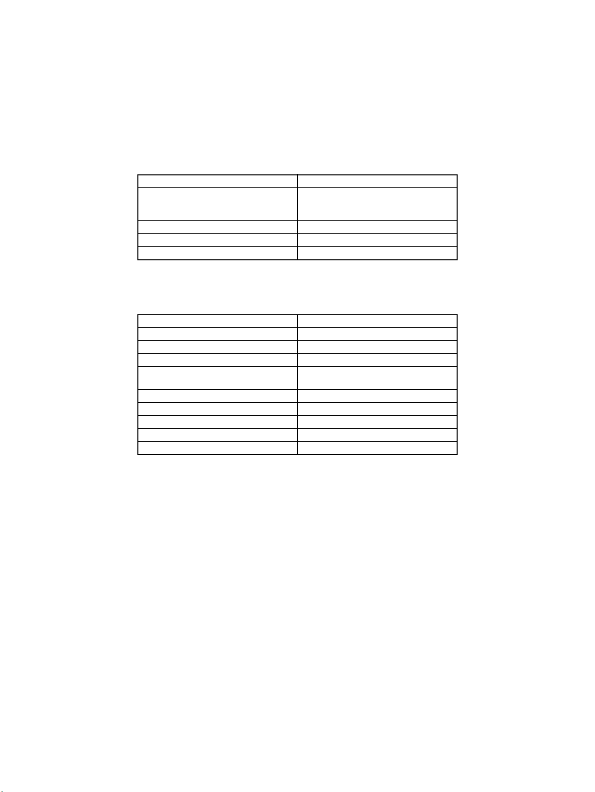
Documents which
cannot be used
Type of Document Possible Trouble
Documents stapled or clipped together Take-up failure, damaged document, defec-
Documents glued together Take-up failure, damaged document
Documents folded, torn, or wrinkled Take-up failure, damaged document
Documents severely curled Documents mis-fed due to being dog-eared
: The following documents, if used in the DF-724, are very
likely to cause trouble.
tive drive train due to jammed staples or
clips.
Documents for which
feeding cannot be
guaranteed
Type of Document Possible Trouble
Slightly curled documents Dog-eared pages, ejection failure
Heat-sensitive paper for facsimile Crease, ejection failure
Coated documents Take-up failure
Documents with uneven surface (letter head
etc.)
Translucent paper Take-up failure, transport failure
Paper just ejected from the ADF Take-up failure, transport failure
Perforated documents (loose leafed etc.) Take-up failure, transport failure
Documents weighing 40 to 50 g/m² Folded leading edge, transport failure
Folded documents Transport failure, distorted image
: The following documents, if used in the DF-724, may or
may not cause trouble.
Take-up failure
M-2
Page 13
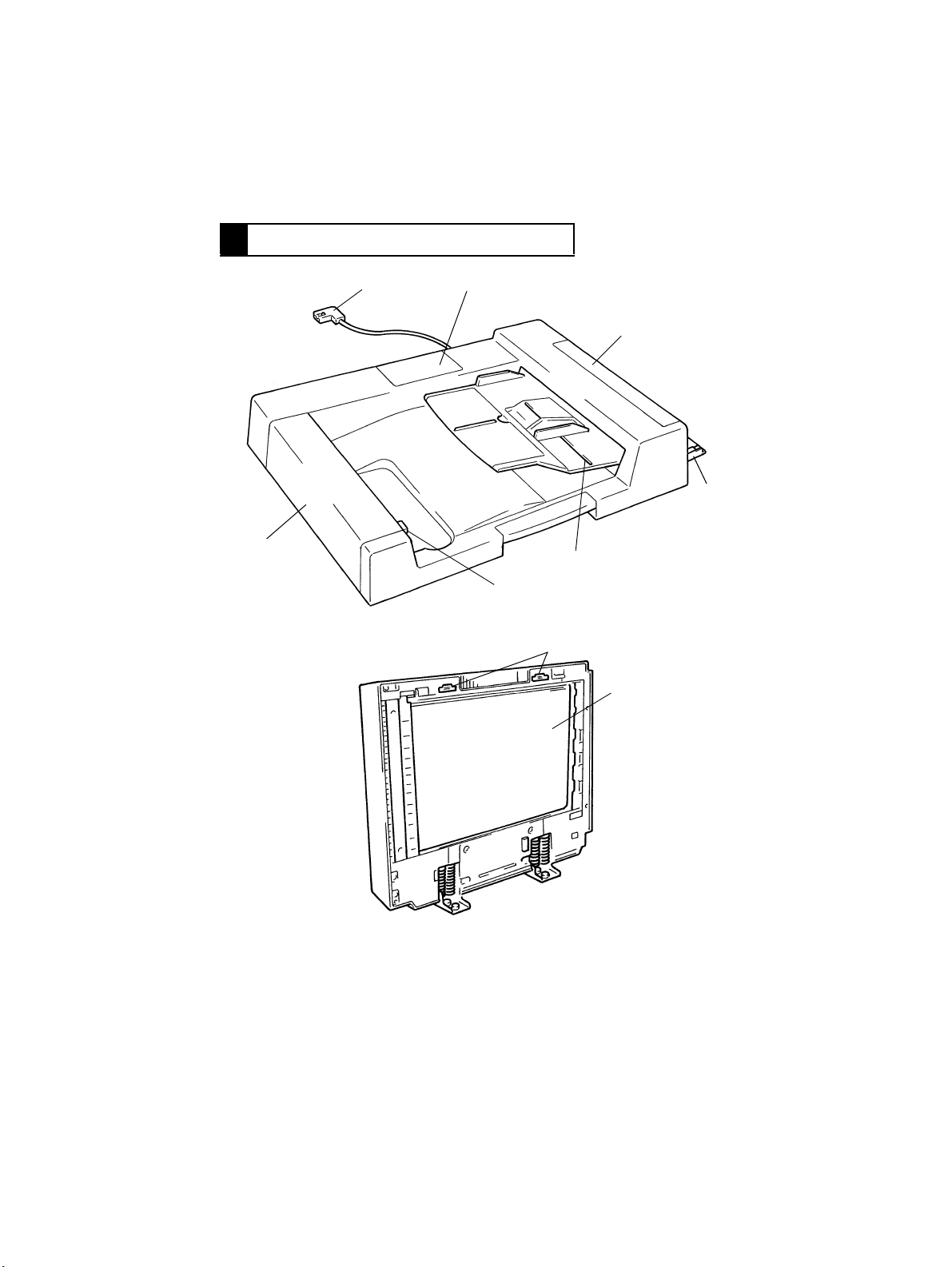
2 COMPONENTS IDENTIFICATION
12
3
4
7
1. Hookup Cord
2. Maintenance Cover
3. Take-Up Cover
4. Single Feed Tray
5. Document Feed Table
5
6
9
6. Turnover Cover Release Switch
7. Turnover Cover
8. Transport Belt
9. Magnet Catches
4486M019AA
8
4486M037AA
M-3
Page 14
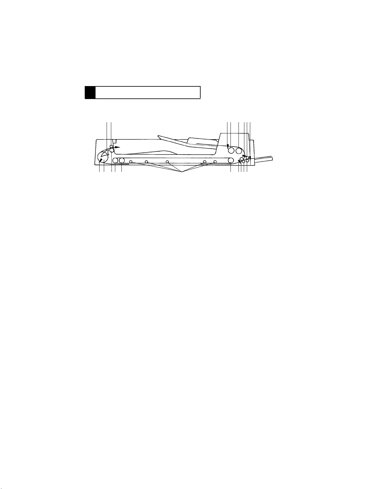
3 CROSS-SECTIONAL VIEW
18 19
13141516
1. Document Detecting Sensor (S1)
2. Document Take-Up Roller
3. Document Separator Roller
4. Registration Sensor
5. Single Feed Transport Roller
6. Manual Feed Take-up Sensor (PWB-D)
7. Single Feed Transport Roll
8. Registration Driven Roller
9. Registration Drive Roller
10. Size Sensor
12 3 456
12
11. Transport Belt Drive Roller
12. Transport Rolls
13. Transport Belt Guide Roller
14. Transport Belt Driven Roller
15. Exit Roller
16. Turnover Roller
17. Turnover/Exit Sensor
18. Turnover/Exit Switching Plate
19. Exit Roll
11 1098717
4486M015AB
M-4
Page 15
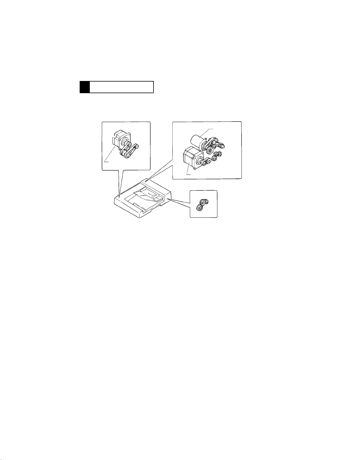
4 DRIVE SYSTEM
Turnover/Exit
Mechanism
Turnover/Exit
Motor (M3)
Take-Up/Transport Mechanism
Take-U p
Motor (M1)
Transport Motor (M2)
Transport Belt Drive Mechanism
4486M038AA
M-5
Page 16
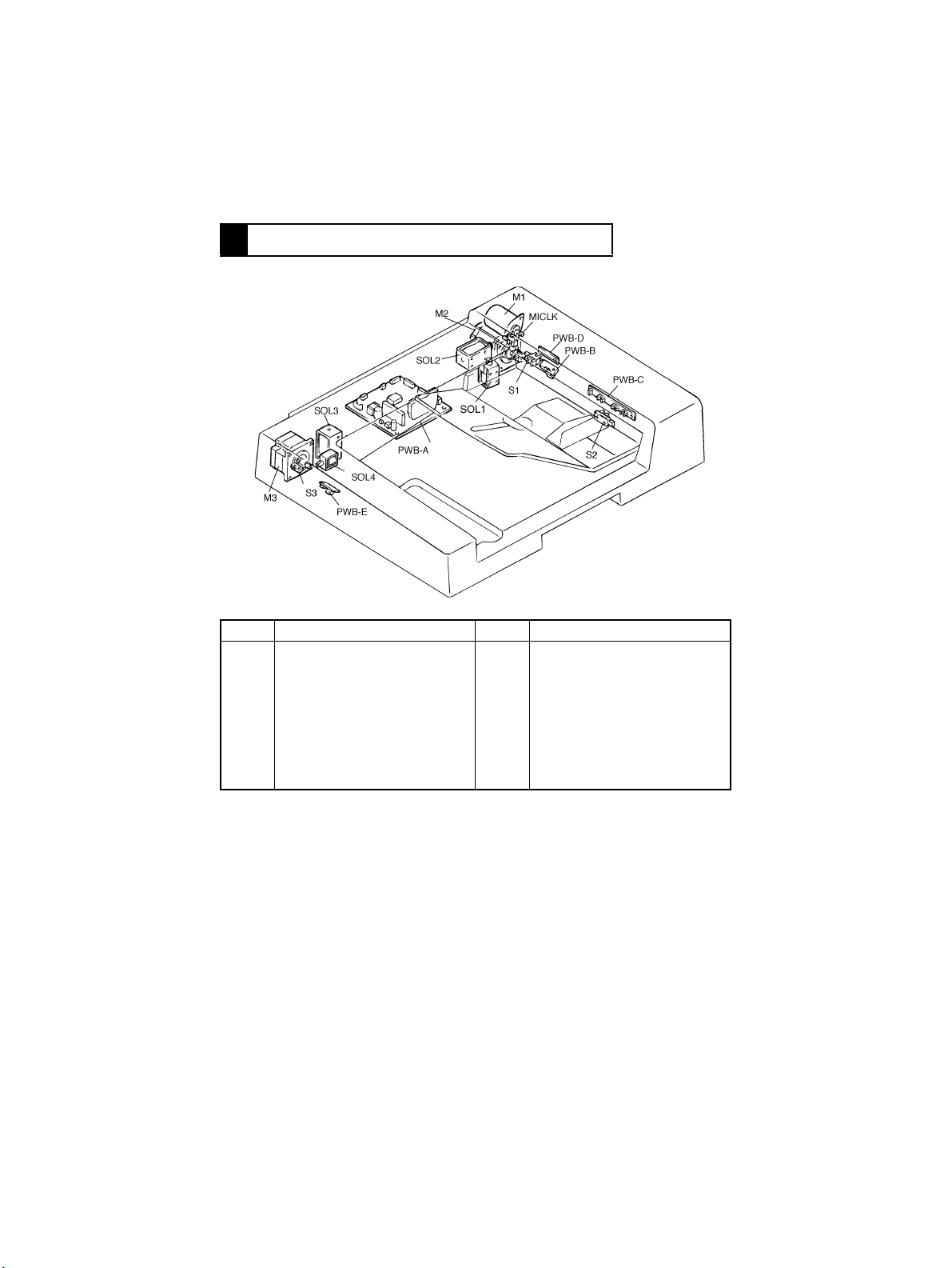
5 ELECTRICAL COMPONENT LAYOUT
Code Name Code Name
PWB-A
PWB-B
PWB-C
PWB-D
PWB-E
M1
M2
M3
Main Control Board
Registration Sensor
Size Sensor
Manual Feed Take-up Sensor
Turnover/Exit Sensor
Take-Up Motor
Transport Motor
Turnover/Exit Motor
SOL1
SOL2
SOL3
SOL4
S1
S2
S3
MICLK
Document Stopper Solenoid
Document Pressure Solenoid
Scale Solenoid
Turnover/Exit Switching Solenoid
Document Detecting Sensor
Feed Cover Set Switch
Turnover Cover Set Switch
Document Feed Motor Pulse
Sensor
4486M039AA
M-6
Page 17

6 DESCRIPTION OF MODES
6-1. Mixed Original Mode
•
If the Mixed Orig key on the control panel is pressed when the copier is set in 1- or 2sided mode, or 2-in-1 mode, the copier detects the size of the document each time a document is taken up and fed in. The copier feeds the copy paper of a size selected from
among the available paper sources according to the document size detected.
6-2. 1-Sided Original Mode
•
When in this mode, the copier detects the size of the document which is taken up and fed
in first.
•
The copier therefore needs to determine the size of the copy paper only once based on
the detected document size and the copying setting made on the control panel. This
makes for faster paper feed timing on the part of the copier.
Note:
If a set of documents of varying sizes are used in this mode, image trouble could result
including missing copy image. (The system does not force a misfeed condition.)
6-3. 2-Sided Mode
•
The copier automatically turns over the 2-sided document for a speedy copying operat ion
(copies are made in the order of the first and second pages).
6-4. 2-in-1 Mode
•
When in this mode, the copier positions two different documents on the Original Glass
side-by-side for making a copy of the two documents onto one side of a single sheet of
paper in a single copy run.
•
If this mode is to be used for a set of documents of different widths, the Mixed Orig key
must first be pressed.
6-5. S -ADF (Single Feed) Mode
•
When a single document is placed in the Single Feed T ra y, the ADF automatically takes it
up and feeds it in to let the copier run a single copy cycle.
Note:
The ADF automatically takes up and feeds in documents even when two or more documents are placed on the Single Feed Tr a y; Howe ver, it could result in a double feed or other
faulty condition. Only one document should therefore be loaded.
6-6. Thin Mode (As set by “Original Thickness” of User’s Mode)
•
When in this mode, the ADF transports the document at a low speed and stops it without
letting it hit against the Original Width Scale.
M-7
Page 18
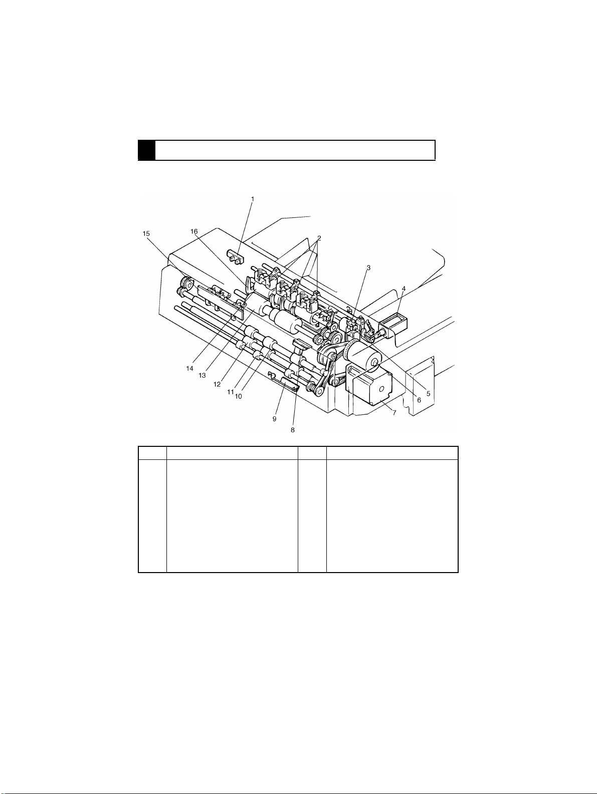
7 DOCUMENT TAKE-UP/FEEDING MECHANISM
7-1. Construction
4486M001AA
No. Name No. Name
1
Feed Cover Set Sensor (S2)
2
Document Pressure Pad
3
Document Feed Motor Pulse
Sensor (M1CLK)
4
Document Pressure Solenoid
(SOL2)
5
Document Stopper Solenoid
(SOL1)
6
Take-Up Motor (M1)
7
Transport Motor
8
Registration Sensor (PWB-B)
9
Manual Feed Take-up Sensor
(PWB-D)
10
Registration Drive Roller
11
Single Feed Transport Roller
12
Registration Driven Roller
13
Document Separator Roller
14
Document Take-Up Roller
15
Size Sensor (PWB-C)
16
Document Stopper Guide Plate
M-8
Page 19

7-2. Document Pick-Up Mechanism
4486M021CA
•
The document pick-up mechanism consists of the Document Pressure Pads, Document
Stopper Guide Plate and Document Take-Up Roller.
•
When documents are loaded on the document feed table, they are pressed against the
Document Take-Up Roller by the Document Pressure Pads, then they are taken up by
the Document Take-Up Roller one by one, commencing with the one from the bottom of
the stack.
•
The Document Stopper Guide Plate determines the leading edge position of the documents loaded in the ADF. It is normally in the raised position, and is lowered at the start
of pick-up motion.
SOL1/2 C ontrol
SOL 1 and 2 are energized and de-energized by the signal output from IC3A on PWB-A.
SOL1 IC3A-20 IC3A-21 SOL2 IC3A-16
ON
(Stopper UP)
OFF
(Stopper
DOWN)
HL
LH
ON H
OFF L
M-9
Page 20
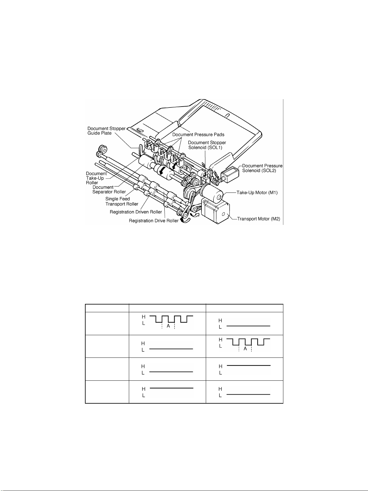
7-3. Document Take-Up Mechanism
4486T02MAA
4486T01MAA
4486T03MAA
4486T02MAA
4486M022CA
•
The document take-up mechanism takes up a document from the bottom of a set of documents loaded on the Single Feed Tray and feeds it up to the registration roller. It is
driven by the Take-Up Motor.
•
The Take-Up motor (M1) rotates the Document Take-Up Roller, Document Separator
Roller and Single Feed Transport Roller via Gears, Pulleys and Timing Belt.
M1 Control
M1 is controlled by the following output signals. M1 speed is detected by the pulse disk
mounted on the motor output shaft and Document Feed Motor Pulse Sensor (M1 CLK). M1
pulses are applied to IC1A-74, and period A is maintained at the same length so that the
motor rotates at a constant speed.
IC3 Forward Backward
Pin 65 (MIL1)
4486T01MAA
Pin 66 (MUL2)
4486T02MAA
Pin 67 (MIHI)
4486T02MAA
Pin 68 (MIL2)
4486T03MAA
M-10
Page 21
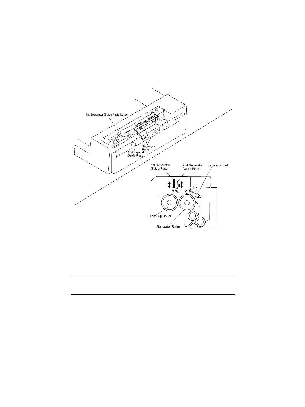
7-4. Separating Mechanism
4486M034CA
4486M023CA
•
Movable Separator Guide Plates are used in the Document Separating Mechanism. The
height of the 1st and 2nd Separator Guide Plates can be adjusted by a lever or scr ews,
respectively.
•
Lowering the Guide Plates can reduce the occurrence of Smudging on the back of documents and smearing of the document image by reducing the number of documents delivered of the Separator Roller.
Note:
Both 1st and 2nd Separator Guide Plates have been set i n the r aised position at the t ime of
shipment from the factory.
•
The Separator Pad is designed to be pressed against the Separator Rollers. This
ensures that documents are transported one by one even if two or more documents are
fed from the Take-Up Roller.
M-11
Page 22
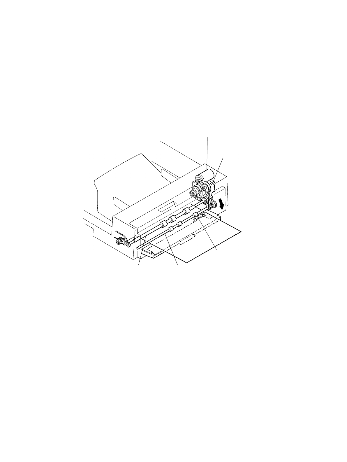
7-5. Single Feed Mechanism
•
The single feed mechanism is used to copy documents one at a time only.
•
Open the Single Feed Tray and set a document in place. The Manual Feed Take-up Sensor (PWB-D) will detect the document and the Single Feed Transport Roller/Registration
Roller begins to rotate to take up the document automatically even if the Start key is not
pressed.
Take-Up Motor (M1)
Transport Motor (M2)
Manual Feed Take-up
Sensor (PWB-D)
Single Feed Transport RollerRegistration Drive Roller
M-12
4486M006AB
Page 23
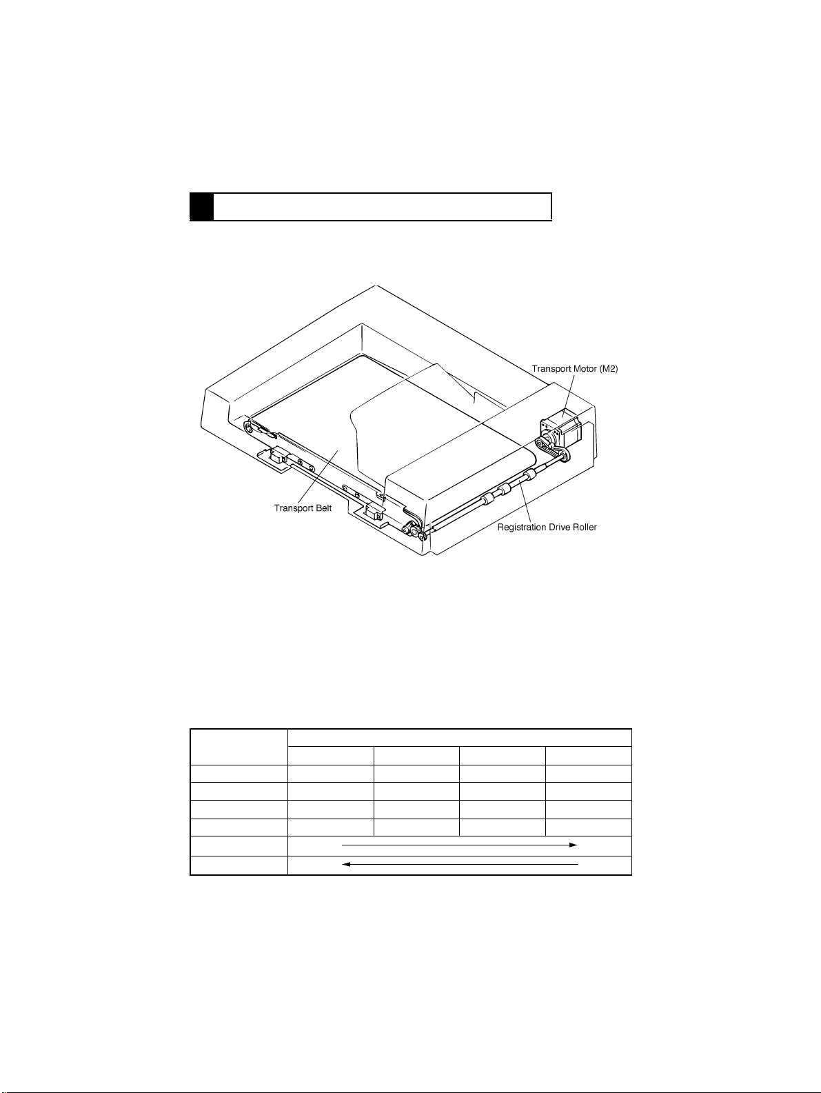
8 DOCUMENT TRANSPORT MECHANISM
8-1. Construction
4486M025CA
8-2. Document Transport Mechanism
•
The document transport mechanism transport the document, which has been fed up to
the Registration Roller from the document take-up mechanism, up to the Original Width
Scale by means of the Document T r ansport Belt.
•
During the turnover motion, the Document Transport Belt is turned to transport the document toward the take-up end.
M2 Control
Whether M2 is turned forward or backward is determined by the combination of the following signals output from IC4 on PWB-A.
IC4
Pin 2 H H L L
Pin 3 L L H H
Pin 6 L H H L
Pin 7 H L L H
Forward Rotation
Backward Rotation
Step 1 Step 2 Step 3 Step 4
Procedure
M-13
Page 24
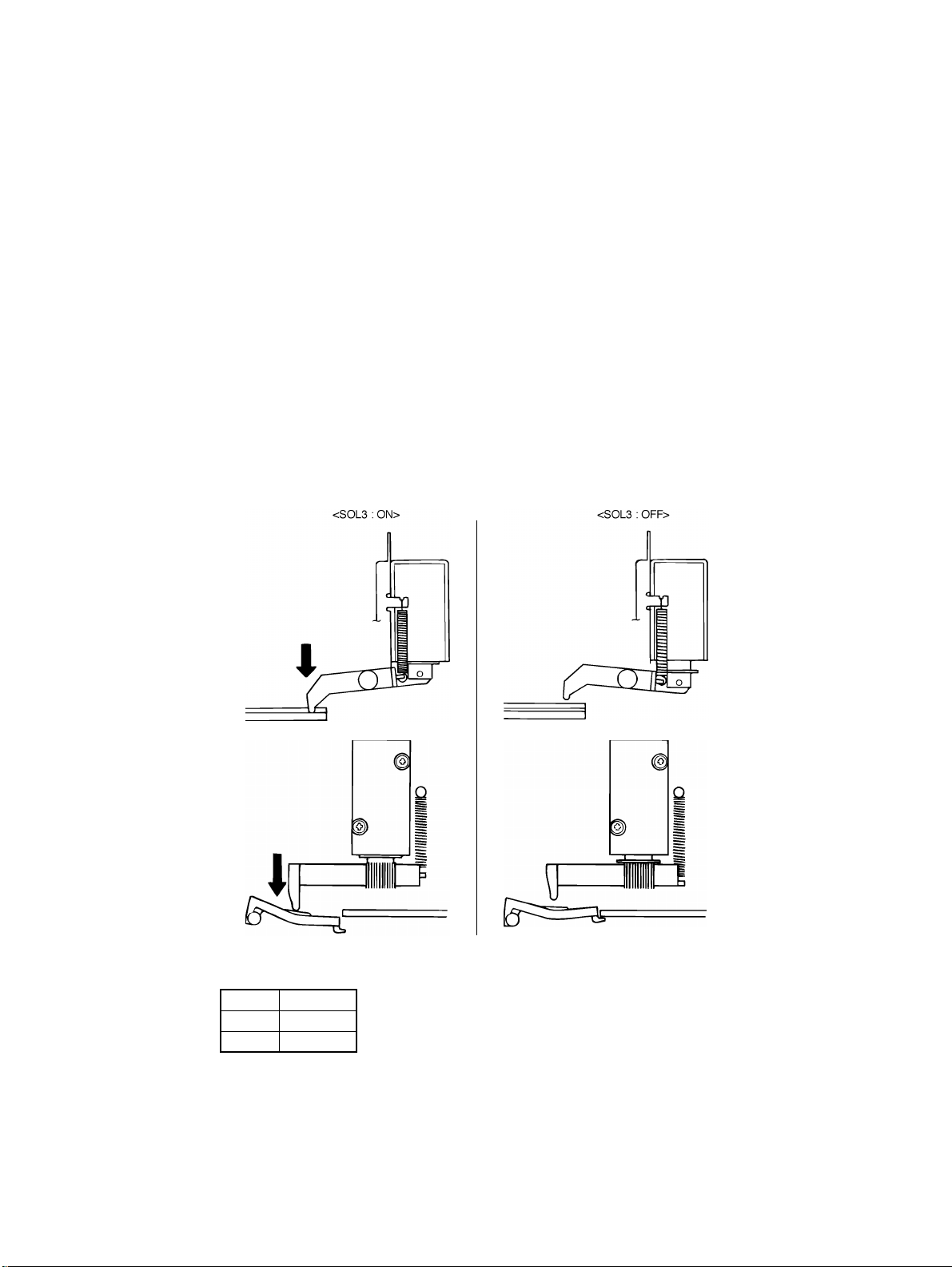
8-3. Original Width Scale Retraction Mechanism
•
When the document is positioned on the Original Glass by the ADF, the leading edge of
the document is pressed against the Original Width Scale to improve positioning accuracy. During turnover and ejection motion, however, the document must move over the
Original Width Scale. For this reason, the Original Width Scale retraction mechanism is
employed.
•
Scale Solenoid SOL3 is used to drive the retraction mechanism.
<Operation>
When the document is positioned : SOL3 is de-energized and the Original Width
Scale is raised by the tension of the Original
Width Scale Spring.
While the document is being transported and during a copy cycle
: SOL3 is energized and the Original Width
Scale is pressed downward by the Original
Width Scale Drive Lever and spring.
4486M026CA
4486D030AA
4486M027CA
4486D032AA
SOL3 Control
The SOL3 is energized and de-energized by the signal output from IC3A on PWB-A.
SOL3 IC3A-14
ON H
OFF L
M-14
Page 25
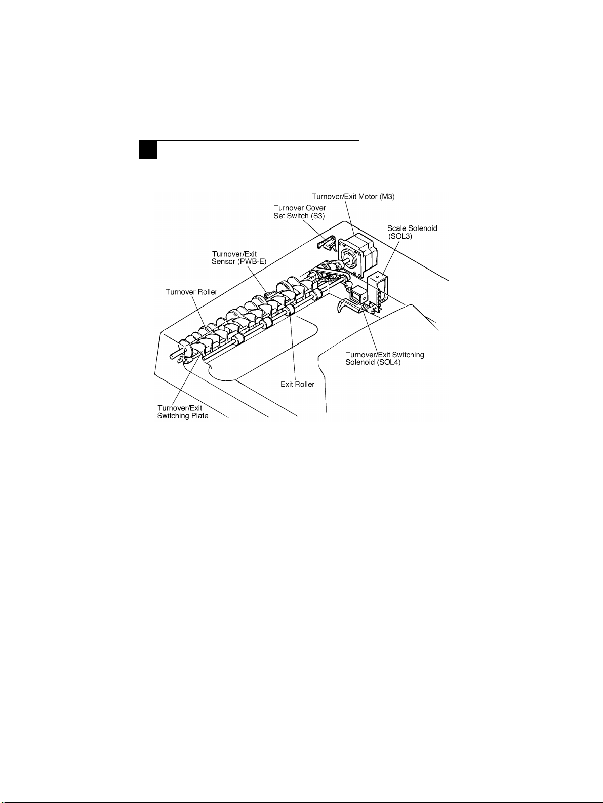
9 TURNOVER/EXIT MECHANISM
9-1. Construction
4486M028CA
M-15
Page 26
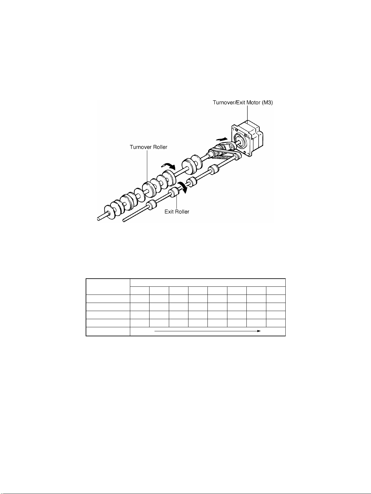
9-2. Turnover/Exit Document Transport Mechanism
4486M030CA
•
The turnover/exit document transport mechanism turns over and ejects the document
which has been transported by the document transport mechanism. It is driven by the
Turnover/ Exit Motor (M3).
•
M3 turns both the Turnover Roller and Exit Roller. These rollers are turned in the same
direction regardless of whether a document is turned over or ejected from the ADF.
M3 Control
Whether M3 is turned forward or backward is determined by the combination of the following signals output from IC13 or PWB-A.
IC13
Pin 2 HHHLLLLL
Pin 3 LLLLHHHL
Pin 6 L L H H H L L L
Pin 7 HLLLLLHH
Forward Rotation
Step 1 Step 2 Step 3 Step 4 Step 5 Step 6 Step 7 Step 8
Procedure
M-16
Page 27
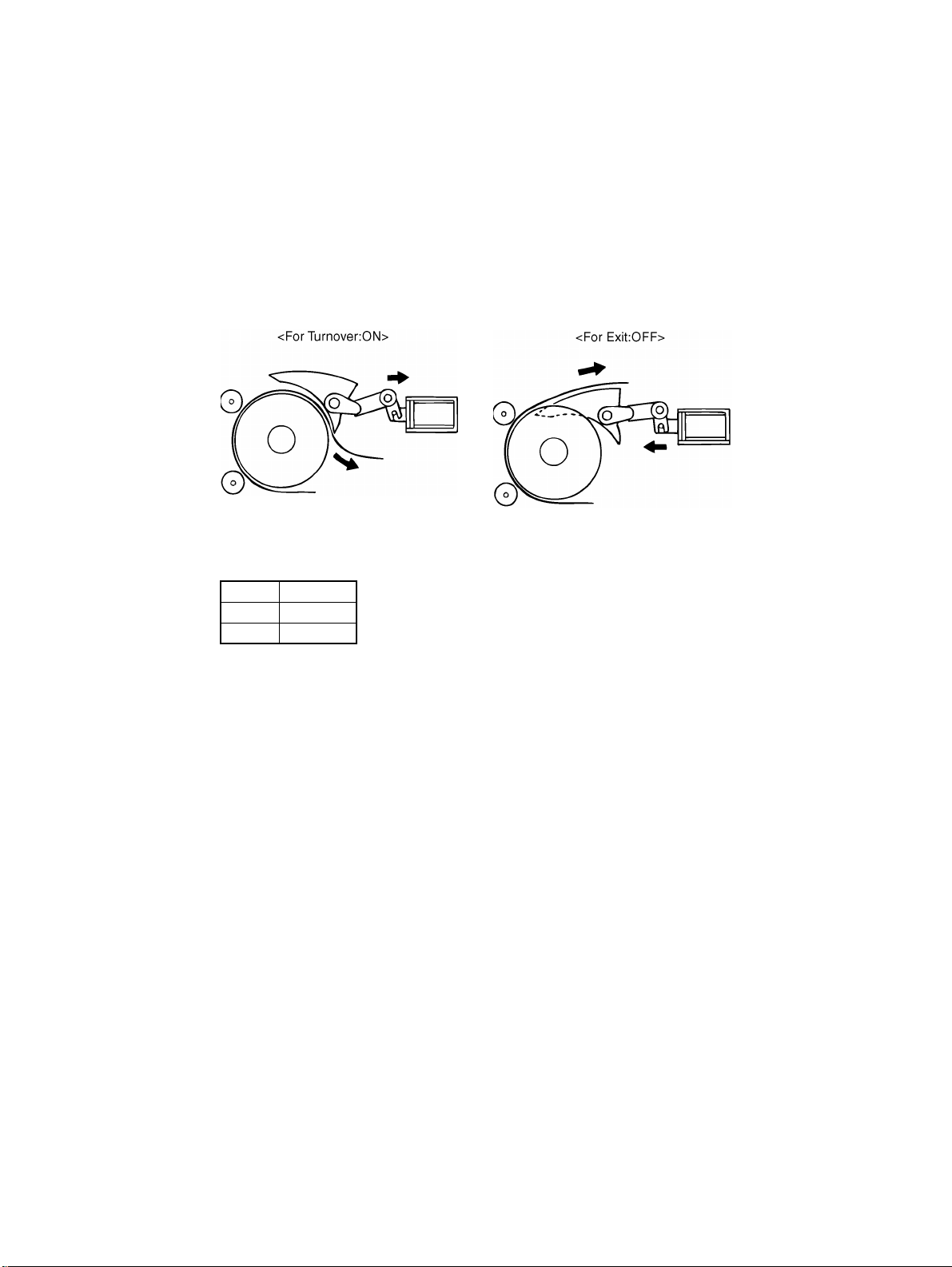
9-3. Turnover/Exit Switching Mechanism
•
The turnover/exit switching mechanism uses the Turnover/Exit Switching Plate which is
swung downward or upward to change the document path, thereby allowing the document to be turned over or ejected from the ADF. This plate is actuated by the Turnover/
Exit Switching Solenoid (SOL4).
4486M031CA
SOL4 Control
The SOL4 is energized and de-energized by the signal output from IC3A on PWB-A.
SOL4 IC3A-17
ON H
OFF L
4486M032CA
M-17
Page 28
10 MISCELLANEOUS
10-1. Document Size Detection Mechanism
1. Width Detection
•
The width of the document is detected by the sensor located on the Size Sensor
(PWB-C).
•
The sensor is turned ON and OFF by actuator located at points approx. 268 mm respectively, from the Rear Document Guide.
2. Length Detection
•
The length of the document is detected by the number of pulses generated by the Transport Motor (M2) for the period in which the Registration Roller starts turning and the trailing edge of the document passes the Registration Sensor (PWB-B).
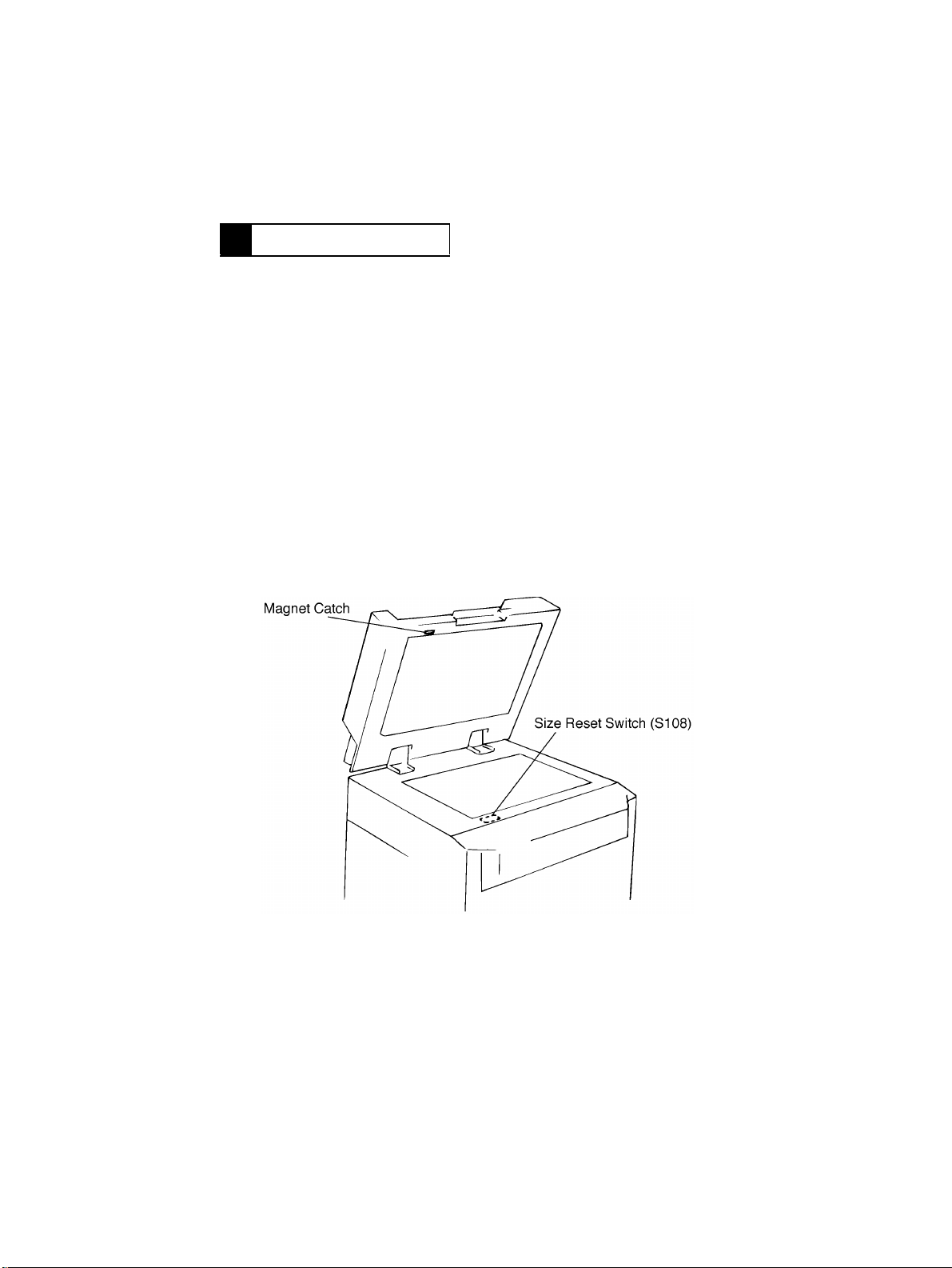
10-2. Raised/Lowered Position Detecting Mechanism
•
DF Set Switch is located at the front left corner of the copier and a magnet catch is
mounted on the front left of the ADF. The position of the ADF, whether raised or lowered,
can be detected as the reed switch is turned ON and OFF by the magnet catch.
•
Opening/closing the ADF serves to reset a misfeed condition and allows selection of a
Test Mode operation.
M-18
4486M033CA
Page 29

TEST MODES
Page 30

Page 31

1 TEST MODES
SW1
PSW1
<Test Mode Setting Procedure>
1. The test mode is initiated when the DIP switch (SW1-6) is set to ON with the Main
Switch of the copier set to OFF and then Main Switch is ON.
SW1-6
2. Various test modes are available. They can be selected by a combination of DIP
switches (SW1-1 to 1-6).
ON
123456
ON Test Mode
OFF Normal Mode
LED5
LED4
LED3
LED2
LED1
4486M014AB
S-1
Page 32

1-1. Paper Passa ge Check
1. With the Main Switch set to OFF, select the desired test mode as shown below.
Transport Speed
High-speed Mode OFF OFF – – – ON
Medium-speed Mode ON OFF – – – ON
Low-speed Mode OFF ON – – – ON
2. Select whether documents are to be fed continuously or intermittently.
Continuous Feed After the desired test mode is selected, turn the Main Switch ON.
Intermittent Feed While holding down PSW1, turn the Main Switch ON.
3. Select the plain paper mode or thin paper mode.
Test Mode SW1-3
Plain Paper OFF
Thin Paper ON
4. Select the desired test mode from the table below, then open and close the ADF to confirm the selection.
Test Mode
1-sided Non-mixed Mode
(high-speed)
1-sided Mixed Mode (normal) ON OFF – – – ON
2-sided Mode OFF ON – – – ON
2-in-1 Mode OFF ON – – – ON
123456
123456
OFF OFF – – – ON
SW1
SW1
✽
The following two modes are available to allow the user to check the actual paper stop
position by stopping the paper without allowing it to contact the Original Width Scale and
then raising the Scale. These modes are available only when the plain paper mode is
selected.
1. 1-sided document
<Setting Method>
•
Turn PSW1 ON with the ADF open, then close the ADF and carry out the test.
2. 2-sided document
<Setting Method>
•
Turn PSW1 ON with the turnover cov er open, then close the cover and carry out the test.
S-2
Page 33

(1) Flow of Paper Passage Test
Select the desired test mode.
Load a required number of sheets of paper on the Single feed Tray, then turn PSW1 ON.
Turning PSW1 ON during a test will interrupt the test. Turning it ON again will eject all the
•
sheets of paper and terminate the test.
In the case of the intermittent mode, the test is carried out each time the PSW1 is turned ON.
•
(2) LED Status when the Copier is in Standby for Paper Passage Test
•
Faulty sections are indicated as foll ows while the copier is in standb y f or a paper passage
test. If no fault is present, all the LEDs (LED1 to 4) will be OFF.
LED
12345
◆❍❍❍
❍◆❍❍
❍❍◆❍
Take-up cover set is faulty.
ADF set is faulty.
Turnover cover set is faulty.
The selected test mode starts.
Description
: For monitoring
❍
: Not lit
◆
: Lit up
Note
LED5 blinks at all times.
S-3
Page 34

1-2. Unit Check
1. Set SW1-6 to ON with the Main Switch set to OFF.
2. Tur n the Main Switch ON, select the desired mode from the following table, then open
and close the ADF to confirm the selection.
Test Mode
Take-Up Motor Check OFF OFF ON OFF OFF OFF
Transpor t Motor Check ON OFF ON OFF OFF OFF
Exit Motor Check OFF ON ON OFF OFF OFF
Solenoid Check ON ON ON OFF OFF OFF
3. Turn PSW1 ON to start th e test.
- Take-Up Motor Check -
4486S001AA
❍
◆
123456
LED Number of
12345
❍❍❍❍
◆❍❍❍
❍◆❍❍
◆◆❍❍
: For monitoring
: Not lit
: Lit up
SW1
Times PSW1 is
Turned ON
0Stop
1 Forward rotation
2Stop
3 B ackward rotation
Operation
S-4
Page 35

- Transport Motor Check -
4486S003AA
- Exit Motor Check -
LED Number of
12345
❍❍❍❍
◆❍❍❍
❍◆❍❍
◆◆❍❍
❍❍◆❍
◆❍◆❍
❍◆◆❍
◆◆◆❍
❍❍❍◆
◆❍❍◆
❍◆❍◆
◆◆❍◆
: For monitoring
❍
: Not lit
◆
: Lit up
Times PSW1 is
Tur ned ON
0Stop
1
2Stop
3
4Stop
5
6Stop
7
8Stop
9
10 Stop
11
Operation
High-speed/
Forward rotation
High-speed/
Backward rotation
Medium-speed/
Forward rotation
Medium-speed/
Backward rotation
Low-speed/
Forward rotation
Low-speed/
Backward rotation
4486S005AA
LED Number of
12345
❍❍❍❍
◆❍❍❍
❍◆❍❍
◆◆❍❍
❍❍◆❍
◆❍◆❍
❍◆◆❍
◆◆◆❍
: For monitoring
❍
: Not lit
◆
: Lit up
S-5
Times PSW1 is
Turned ON
0Stop
1
2Stop
3
4Stop
5
6Stop
7 Eject speed
Operation
High-speed/
Rotation
Medium-speed/
Rotation
Low-speed/
Rotation
Page 36

- Solenoid Check -
4486S007AA
LED Number of
12345
❍❍❍❍
◆❍❍❍
❍◆❍❍
◆◆❍❍
❍❍◆❍
◆❍◆❍
❍◆◆❍
◆◆◆❍
: For monitoring
❍
: Not lit
◆
: Lit up
Times PSW1 is
Turned ON
0Stop
1 SOL1: Descent
2 SOL1: Ascent
3 SOL2: ON
4 SOL2: OFF
5 SOL3: ON
6 SOL3: OFF
7 SOL4: ON
Operation
1-3. Sensor Check
1. Set the SW1-6 to ON with the Main Switch set to OFF.
2. Tur n the Main Switch ON, select the desired mode from the following table, then open
and close the ADF to confirm the selection.
Test Mode
Paper Passage Sensor OFF OFF OFF OFF OFF OFF
Cover Sensor ON OFF OFF OFF OFF OFF
Other Sensors OFF ON OFF OFF OFF OFF
123456
SW1
3. Block each sensor with a piece of paper etc. to check whether the corresponding LED
lights up.
LED Status
Paper is present : Lit
No paper present : Not lit
S-6
Page 37

- Paper Passage Sensor Check -
4486S009AA
4486S010AA
- Cover Sensor Check -
4486S011AA
4486S012AA
- Other Sensors Check -
LD1 :Document Detecting Sensor (S1)
LD2 :Manual Feed Take-up Sensor (PWB-D)
LD3 :Registration Sensor (PWB-B)
LD4 :Tur nover/Exit Sensor (PWB-E)
LD1 :Feed Cover Set Sensor (S2)
LD2 :Size Reset Switch (S108)
LD3 :Turnover Cover Set Switch (S3)
4486S013AA
LD1 :Size Sensor (Rear)
4486S014AA
LD2 :Size Sensor (Center)
LD3 :Size Sensor (Front)
LD4 :Document Feed Motor Pulse Sensor (M1CLK)
PWB-C
Note1
LD1, LD3 Japan Only
Note2
LD4 (Document Feed Motor Pulse Sensor) lights up when the sensor is blocked, and goes
out when the sensor is unblocked.
S-7
Page 38

1-4. Sensor Adjustment Check
1. Set the SW1-6 to ON with the Main Switch set to OFF.
2. T urn the Main Switch ON, select the sensor adjustment mode as shown in the following
table, then open and close the ADF to confirm the selection.
Test Mode
Sensor Adjustment ON OFF OFF ON OFF OFF
3. Turn the PSW1 ON to start the test.
123456
SW1
Note
An error will occur if adjustment is carried out with the take-up/turnover cover open. So
make sure that the cover is closed before starting adjustment.
- Registration Sensor Adjustment -
LED1 LED2 S ensor Status
4486S015AA
- Exit Sensor Adjustment -
4486S016AA
❍❍
❍◆
◆❍
◆◆
LED3 LED4 Sensor Status
❍❍
❍◆
◆❍
◆◆
❍
: Not lit
◆
: Lit up
Initialized
Upper-limit error
Lower-limit error
Adjustment complete
Initialized
Upper-limit error
Lower-limit error
Adjustment complete
S-8
Page 39

DIS/REASSEMBLY,
ADJUSTMENT
Precautions for Disassembly, Reassembly, and Adjustment
CAUTION
1. Before attempting to disassemble the DF-724, always make sure that no power is being
supplied from the copier.
2. While power is being supplied to the DF-724, do not attempt to remove/install the print
jacks from/to the PWBs or unplug/plug in the connectors.
3. If the DF-724 is run with its Covers removed, use care not to allow your clothing to be
caught in revolving parts such as the Timing Belt.
4. The basic rule is do not run the DF-724 any time during dis/reassembly.
Important
1. A toothed washer is used with the screw that secures the ground wire to ensure positive
conduction. Do not forget to insert this washer at reassembly.
2. To reassemble the DF-724, reverse the order of disassembly unless otherwise specified.
3. Do not attempt to loosen or remove the screw to which red paint has been applied.
Purpose of Applying Red Paint
Red paint is applied to those screws that cannot be readjusted or reinstalled in the field.
4. Do not attempt to loosen or remove the two screws that secure the Right Hinge through
those screws are not painted red. (Metric Areas Only)
Page 40

Page 41

1 DISASSEMBLY
1-1. Removal of the Document Transport Belt
•
Push the lever to the left, then snap off the C clip to release the Belt assy.
•
Hold the top of the Transport Belt Assy and tilt the Assy towards you to remove it.
4486D001AA
•
Remove two screws as shown in the figure, then bend the Exit Roller side to remove the
Transport Belt.
4486D002AA
D-1
Page 42

1-2. Removal of the Document Take-Up Roller Assy
•
Remove the Transport Belt, then remove the Cover and Document Stopper Guide Plate
to remove the Take-Up Roller Assy.
4486D003AA
1-3. Removal of the Document Take-Up and Separator Rollers
•
Snap off the four C clips, then remove the rollers one by one.
NOTE
Take care not to lose the two pins attached to the Document Take-Up Roller.
D-2
4486D040CA
Page 43

1-4. Removal of the Separator Pad
•
Open the Single Feed Single Feed Tray and Feed Cover, then remove four screws to
remove the Feed Cov er.
•
Push each Separator Pad to slide it upwards and remove it.
4486D011AA
D-3
Page 44

1-5. Removal of the Document Take-Up Unit Assy
•
Remove the Transport Belt.
•
Remove the Maintenance Cover and unplug the connectors from PWB-A as shown in the
figure. Remove the Single Feed Tray.
4486D005AA
•
Remove the ADF from the copier, and place it on a table upside down.
•
Remove the Cover.
•
Remove five screws, open the Feed Cover and lift out the Document Take-Up Unit Assy.
4486D006AA
NOTE
When reinstalling the Document Take-Up Unit Assy, make sure that the Feed Cover is
•
open. Tighten the five screws lightly by hand, then tighten securely after the ADF is reinstalled on the copier.
D-4
Page 45

1-6. Removal of the Turnover/Exit Assy
•
Remove the Transport Belt, Maintenance Cover and unplug the connectors from PWB-A
as shown in the figure.
•
Open the Turnover/Exit Cover and remove the screw.
4486D007AA
•
Remove the Cover and grounding wire (black).
•
Remove five screws, open the Turnover/Exit Cover and lift out the Turnover/Exit Unit
Assy.
4486D008AA
NOTE
When reinstalling the Turnover/Exit Unit Assy, make sure that the Turnover/Exit Cover
is open.
D-5
Page 46

1-7. Removal of the Take-Up Motor/Transport Motor Unit
•
Remove the Take-Up Unit Assy.
•
Remove three screws, unplug f rom connectors, tak e out two wire saddles and a spring to
remove the Motor Unit.
4486D010AA
D-6
Page 47

2 ADJUSTMENTS
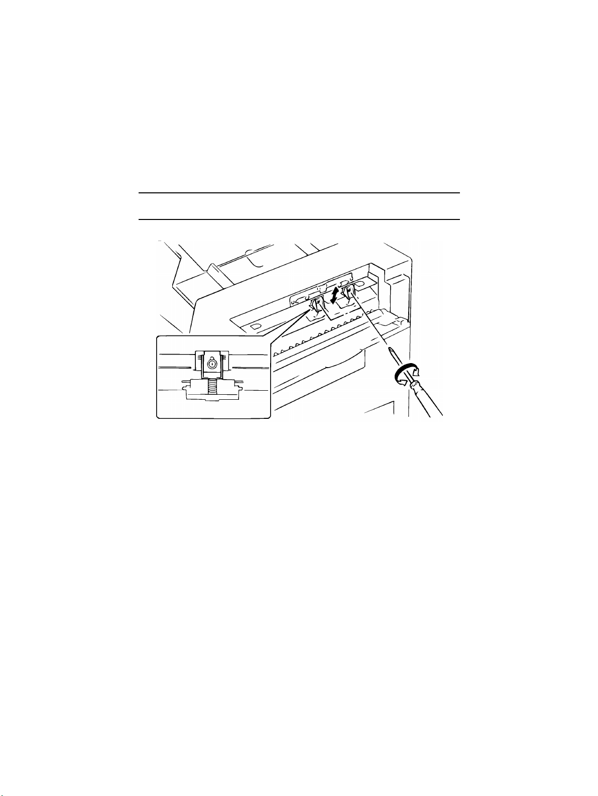
2-1. Adjustment of Magnet Height
Requirement
The clearance between the Magnetic Catch and Original Glass should be 0 to 0.5 mm.
•
1. Remove the Transport Belt and two Screw Covers. (Push up from inside)
4486D012AB
2. Set the T ransport Belt and, close the ADF, loosen the Magnetic Catch adjusting screws,
check the clearance of the Magnet Catch, then tighten the adjusting screws.
D-7
4486D013AA
Page 48

2-2. Adjustment of the Document Feed Table
Requirement
The document Feed Table should be positioned within 0±1 mm from the edge of the Doc-
•
ument Positioning Plate.
1. Slide the Document Positioning Plate towards the rear and secure it with tape.
2. Affix a piece of tape to each of the Magnet Catch Plates.
4486D014AB
4486D045AA
3. Place a document on the Document Feed Table and select 1-sided mode.
4. Press the Start key, then press the Stop key immediately.
5. Open the ADF gently and remove the tape from the Document Positioning Plate, taking
care not to allow the document to move.
6. Check whether the document is aligned with the edge of the Document Positioning
Plate.
7. If the document is off in direction “a”, move the Document Feed Table towards you. If
the document is off in direction “b”, move the Document Feed Table towards the rear.
a
b
4486D015AA 4486D034AA
D-8
Page 49

2-3. Adjustment of the Single Feed Tray
Requirement
The document Feed Table should be positioned within ±1 mm from the edge of the Doc-
•
ument Positioning Plate.
1. Slide the Document Positioning Plate towards the rear and secure it with tape.
2. Affix a piece of tape to each of the Magnet Catch Plates.
4486D014AB
4486D045AA
3. Place a document on the Document Feed Table and select 1-sided mode.
4. Press the Start key, then press the Stop key immediately.
5. Open the ADF gently and remove the tape from the Document Positioning Plate, taking
care not to allow the document to move.
6. Check whether the document is aligned with the edge of the Document Positioning
Plate.
7. If the document is off in direction “a”, move the Single Feed Tray to wards y ou. I f the document is off in direction “b”, move the Single Feed Tray towards the rear.
a
b
4486D015AA
4474U008AA
D-9
Page 50

2-4. Adjustment of Document Stop Position in the 1-Sided Mode
Requirement
The document should be 0 to 1 mm in the direction of b from the end face of the Original
•
Width Scale.
1. Set “U-4” (Lightweight Original) of User’s Choice to “1.” (Make the adjustment in the
Lightweight Original mode.)
NOTE
Metric areas only
2. Slide the Document Positioning Plate towards the rear and secure it with tape.
3. Affix a piece of tape to each of the Magnet Catch Plates.
4486D014AB
4. Place a document on the Document Feed Table, and select 1-sided original/1-sided
copy mode.
5. Press the Start key, then press the Stop key immediately.
6. Open the ADF gently and check whether the document is aligned with the edge of the
Original Glass.
7. Set the service choice mode “c-31”.
8. Referring to page D-16, adjust the document stop position.
ab
4486D016AA
4486D045AA
D-10
Page 51

2-5. Adjustment of Document Stop Position in the 2-Sided Mode
Requirement
The document should be 0 to 1 mm in the direction of b from the end face of the Original
•
Width Scale.
1. Set “U-4” (Lightweight Original) of User’s Choice to “1.” (Make the adjustment in the
Lightweight Original mode.)
NOTE
Metric areas only
2. Slide the Document Positioning Plate towards the rear and secure it with tape.
3. Affix a piece of tape to each of the Magnet Catch Plates.
4486D014AB
4. Place a document on the Document Feed Table, and select 2-sided original/1-sided
copy mode.
5. Press the Start key, then press the Stop key immediately.
6. Open the ADF gently and check whether the document is aligned with the edge of the
Original Glass.
7. Set the service choice mode “c-32”.
8. Referring to page D-16, adjust the document stop position.
ab
4486D016AA
4486D045AA
D-11
Page 52

2-6. Adjustment of Document Stop Position in the 2-in-1 Mode
Requirement
The document should be 0 to 1 mm in the direction of b from the end face of the Original
•
Width Scale.
1. Set “U-4” (Lightweight Original) of User’s Choice to “1.” (Make the adjustment in the
Lightweight Original mode.)
NOTE
Metric areas only
2. Slide the Document Positioning Plate towards the rear and secure it with tape.
3. Affix a piece of tape to each of the Magnet Catch Plates.
4486D014AB
4. Place two A4Y documents on the Document Feed Table, and select 1-sided original/1sided 2-in-1 copy mode.
5. Press the Start key, then press the Stop key immediately.
6. Open the ADF gently and check whether the document is aligned with the edge of the
Original Glass.
7. Set the service choice mode “c-33”.
8. Referring to page D-16, adjust the document stop position.
ab
4486D016AA
4486D045AA
D-12
Page 53

2-7. Adjustment of Distance Between Documents in the 2-in-1
Mode
Requirement
The second document should be 0 to 1 mm in the direction of b from the trailing edge of
•
the first document.
1. Set “U-4” (Lightweight Original) of User’s Choice to “1.” (Make the adjustment in the
Lightweight Original mode.)
NOTE
Metric areas only
2. Slide the Document Positioning Plate towards the rear and secure it with tape.
3. Affix a piece of tape to each of the Magnet Catch Plates.
4486D014AB
4. Place two A4Y documents on the Document Feed Table, and select 1-sided original/1sided 2-in-1 copy mode.
5. Press the Start key, then press the Stop key immediately.
6. Open the ADF gently and check whether the 2nd document is positioned correctly in
relation with the 1st document.
7. Set the service choice mode “c-34”.
8. Referring to page D-16, adjust the document stop position.
ab
4486D017AA
4486D045AA
D-13
Page 54

2-8. Adjustment of Document Stop Position in the Single Feed
Mode
Requirement
The document should be 0 to 1 mm in the direction of b from the end face of the Original
•
Width Scale.
1. Set “U-4” (Lightweight Original) of User’s Choice to “1.” (Make the adjustment in the
Lightweight Original mode.)
NOTE
Metric areas only
2. Slide the Document Positioning Plate towards the rear and secure it with tape.
3. Affix a piece of tape to each of the Magnet Catch Plates.
4486D014AB
4. Place a document into the Manual Feed Port, and press the Stop key immediately.
5. Open the ADF gently and check whether the document is aligned with the edge of the
Original Glass.
6. Set the service choice mode “c-37”.
7. Referring to page D-16, adjust the document stop position.
ab
4486D016AA
4486D045AA
D-14
Page 55

2-9. Adjustment of ADF Registration Loop
1. Place a document on the Document Feed Table and press the Start key.
2. Change the setting for service choice “c-38”, remove the document and place it on the
Document Feed Table again, then press the Start key.
3. Referring to the table below, repeat steps 1 and 2 until the document is positioned so
that it can be transported by the Transport Belt.
Setting Method
➝
A. Press the Stop
B. Select the desired mode, then press the Start key.
C. Press the Clear key to clear the currently selected value.
D. Referring to the table below, enter a setting equivalent to the deviation.
E. Press the Start key to confirm the entry.
F. Press the Reset key twice to return to the main screen.
Stop Position Adjustment Table
0 ➝ Stop ➝ 1 ➝ 2keys in that order
Setting
Deviation
(mm)
43 7
44 6 52 2
45 5 53 3
46 4 54 4
47 3 55 5
48 2 56 6
49 1 57 7
50 0 Default 58 8
Direction Setting
51 1
Moves in direction “a”
(towards the Original
Width Scale)
Deviation
(mm)
Direction
Moves in direction “b”
(towards the Take-Up
Mechanism)
D-15
Page 56

2-10. Adjustment of Document Stopper Solenoid SOL1
1. Remove the Document Take-Up Unit Assy and place it on a table upside down.
2. Loosen two screws and bring the brush (marked “A” in the figure) of the Document
Stopper Guide Plate into contact with the Take-Up Roller.
3. While pressing the Document Stopper Guide Plate against the Take-Up Roller gently,
lift the solenoid by holding the two screws until it comes to a stop, then tighten the
screws.
4486D018AA
Note
After completion of adjustment, lift the Document Stopper Guide Plate to check that the
Guide Plate is supported smoothly by the retaining force of the solenoid.
D-16
Page 57

2-11. Adjustment of Document Pressure Solenoid SOL2
Requirement
The clearance between the Guide Plate and Wei ght Le v er should be appro x imately 2 ± 1
•
mm.
1. Remove the Document Take-Up Unit Assy, and place it on a table.
2. Loosen two screws.
3. While pushing the Plunger towards the Solenoid (up to the position at which the Plunger
stops), move the Solenoid so that the clearance between the Guide Plate and Weight
Lever is within the specified range.
Note
When moving the Solenoid, make sure that the Plunger is pushed towards the Solenoid
and that there is no play between the Plunger and Weight Lever.
D-17
4486D019AA
4486D020AA
Page 58

2-12. Adjustment of Scale Solenoid SOL3
Requirement
The exposed end of the Stopper Lever is positioned within approximately 8.7 ± 0.2 mm in
•
length.
1. Remove the Turnover/Exit Unit Assy and place it on a table upside down.
2. Loosen two screws.
3. Move the Solenoid up and down so that the exposed end of the Stopper Lever is within
the specified length.
4. Tighten the two screws.
D-18
4486D021AA
4486D022AA
Page 59

2-13. Adjustment of Turnover/Exit Switching Solenoid SOL4
1. Remove the Turnover/Exit Unit Assy and place it on a table.
2. With sponge fitted to the Turnover/Exit Cover in contact with the Turnover/Exit Switching
Plate, move the solenoid to the right and left to obtain a clearance “0” at part A shown in
the figure, move the solenoid to the right or left so that the gap indicated by “A” in the
figure is eliminated.
3. Tighten the two screws.
4486D023AC
Sponge
A
4486D024AC
D-19
Page 60
2-14. Adjustment of the Separating Pressure of Document
Separator Pad
1. Remove the Take-Up Unit Cover.
2. Loosen each screw and tighten it to an appropriate level.
Note
Make sure that the separating pressure of both pads is the same.
4486D025AA
D-20
Page 61

2-15. Adjustment of the Distance Between Separator Rollers
Requirement
When the 2nd Separator Guide Plate is lowered, one sheet of paper can pass through,
•
but not two, so that two sheets of paper are properly separated from each other.
<When the Separator Rollers are in contact with the 2nd Separator Guide Plate>
1. Open the Take-Up Cover and loosen the two screws on the 2nd Separator Guide Plate.
2. Cut out two pieces of paper, each measuring about 200 mm by 50 mm, and insert one
each between the guide plate and the roller from the take-up end as you turn the roller.
4474D004AA
3. While holding down the 2nd Separator Guide Plate mounting bracket so that the spring
tension from the bracket acts on the paper uniformly on the front and rear sides, hold
the guide plate in position and, at the same time, tighten the two scerws.
4474D005AA
4474D001AA
D-21
Page 62

4. Remove the paper. Place one piece of paper on top of another and place the t wo pieces
of paper at the separating position from the take-up end.
5. Tur n the Separator Rollers and check that the two pieces of paper are properly separated from each other by the guide plate and only one piece of paper is taken up and
fed in. Make this check for the front and rear Separator Rollers.
Note
If two pieces of paper are taken up and fed in, or if the Separator Rollers are in contact with
the 2nd Separator Guide Plate when they are turned with no paper placed, start the procedure over beginning with step 2.
4477D003AA
6. Loosen the two screws on the mounting bracket. Raise t he mounting brac k et as far as it
will go and, keeping the bracket in that position, tighten the two screws.
7. Loosen the two screws that secure the 2nd Separator Guide Plate in position. Raise the
guide plate as far as it will go and, keeping the plate in that position, tighten the two
screws.
4474D006AA
4474D007AA
D-22
Page 63

<When there is a gap between the Separator Roller and 2nd Separator Guide Plate wipe
enough to allow two or more sheets of paper to pass through>
1. Open the Take-Up Cover and loosen the two screws on the 2nd Separator Guide Plate
mounting bracket and 2nd Separator Guide Plate.
2. Cut out two pieces of paper, each measuring about 200 mm by 50 mm, and insert one
each between the guide plate and roller from the take-up end as you turn the roller.
4474D009AA
4474D001AA
3. Apply the tip of a flat-blade screwdriver to the center of the mounting bracket.
4. Lightly pushing the screwdriver down from the above (with a for ce equivalent to spring
tension), tighten the two screws on the guide plate.
4474D008AA
D-23
Page 64

5. Remove the paper. Place one piece of paper on top of another and place the t wo pieces
of paper at the separating position from the take-up end.
6. Tur n the Separator Rollers and check that the two pieces of paper are properly separated from each other by the guide plate and only one piece of paper is taken up and
fed in. Make this check for the front and rear Separator Rollers.
Note
If two pieces of paper are taken up and fed in, or if the Separator Rollers are in contact with
the 2nd Separator Guide Plate when they are turned with no paper placed, start the procedure over beginning with step 2.
4474D003AA
7. Loosen the two screws on the mounting bracket. Raise t he mounting brac k et as far as it
will go and, keeping the bracket in that position, tighten the two screws.
8. Loosen the two screws that secure the 2nd Separator Guide Plate in position. Raise the
guide plate as far as it will go and, keeping the plate in that position, tighten the two
screws.
4474D006AA
4474D007AA
D-24
Page 65

TROUBLESHOOTING
General Precautions
CAUTION
1. When servicing the DF-724 with its covers removed, use utmost care to prevent your
hands, clothing and tools from being caught in revolving parts.
2. Before attempting to replace parts and unplugging connectors, make sure that no
power is being supplied from the copier.
Important
1. When creating a closed circuit and measuring a voltage across connector pins specified in the text, be sure to use the green wire (GND).
2. Keep all disassembled parts in good order and keep tools under control so that none
will be lost or damaged.
Reading the Text
1. If a component on a PWB or any other functional unit including a motor is defective, the
text only instructs you to replace the whole PWB or functional unit and does not give
troubleshooting procedure applicable within the defective unit.
2. The text assumes that there are no breaks in the harnesses and all connectors are
plugged into the right positions.
Page 66

Page 67

1 MISFEED DETECTION
•
Misfeed at the ADF Take-Up/Single Feed Section
Description Detection Timing
Document not reaching Registration Sensor
(PWB-B)
Take-Up Motor (M1)
malfunction
•
Misfeed at the Transport Section
Description Detection Timing
Document staying at
Registration Sensor
(PWB-B)
Document staying on
Glass (before operation)
Document staying on
Glass (after operation)
•
Misfeed at the Turnover/Exit Section
Description Detection Timing
Document not reaching Exit Sensor
(PWB-E)
(during ejection/turnover)
Document staying at
PWB-E (during ejection)
Document staying at
PWB-E (durin g turnover)
PWB-B is not activated within a given period time after Take-Up
Motor (M1) is energized.
Document Feed Pulse Sensor (M1CLK) is not activated within a
given period time after M1 is energized.
PWB-B is not activated even if the next document has reached
the scan position.
A sensor indicates that there is still a document in the document
path when the next document is placed on the Document Feed
Table and all covers are closed.
Exit Sensor (PWB-E) is activated when a 1st document is taken
up and fed in.
S4 is not activated within a given period time after Turnover/Exit
Motor (M3) is energized.
PWB-E S4 is not deactivated within a given period time after
PWB-E is activated.
PWB-E S4 is not deactivated within a given period time after
PWB-E is activated.
T-1
Page 68

2 TROUBLESHOOTING PROCEDURE
1. Mis-feed at the ADF Take-Up Section
Symptom
•
The document is
not taken up at
all.
Step
No.
1 Does the document used meet
the specifications for reliable
feeding?
2 Has the capacity of the Docu-
ment Feed Table been
exceeded?
3 Are any of the Document Take-
Up Rollers, Document Separator
Rollers and Document Separator
Pads deformed, worn or dirty
with paper dust?
4 Carry out the unit test for the
Document Pressure Solenoid
(SOL2) to check whether it functions properly .
5 Does the voltage across CN9-2
on PWB-A and GND change
from 24 VDC when the Start key
is pressed?
6 Carry out the unit test for the
Document Stopper Solenoid
(SOL1) to check whether it functions properly .
7 Does the voltage across CN12-3
on PWB-A and GND change
from 24 VDC to 0 VDC instantaneously and then return to 24
VDC when the Start key is
pressed?
8 Carry out the unit test for the
Document Feed Motor Pulse
Sensor (M1CLK) to check
whether it functions properly.
9 Does the voltage across CN5-3
on PWB-A and GND change to
“H” when M1CLK is blocked and
change to “L” when M1CLK is
unblocked, when the pulse disk is
turned by hand?
10 Carry out the unit test for the
Take-Up Motor (M1) to check
whether it functions properly.
Check Item Result Action
NO Instruct the user to
use documents
that meet the
specifications for
reliable feeding.
YES Instruct the user
not to exceed the
capacity.
YES Clean or replace
them.
YES Carry out step 6.
YES Replace SOL2.
NO Replace PWB-A.
YES Carry out step 8.
YES Replace SOL1.
NO Replace PWB-A.
YES Carry out step 10.
YES Replace PWB-A.
NO Replace.
YES Check each gear
for damage.
T-2
Page 69

Symptom Step
•
The document is
not taken up at
all.
•
The panel indicates a misfeed
in the ADF when
the Start key is
pressed, though
no documents
are placed on
the Document
Feed Table.
•
The document is
not taken up in
single feed
mode.
No.
Check Item Result Action
11 Does the voltage across CN6-1
on PWB-A and GND change
from 24 VDC when the Start key
is pressed?
1 Does the actuator of the Docu-
ment Detecting Sensor (S1) function properly?
2 Carry out the unit test for S1 to
check whether it functions properly.
3 Does the voltage across CN3-12
on PWB-A and GND change
from 5 VDC to 0 VDC when the
actuator is lifted by hand?
1 Does the actuator of the Manual
Document Detecting Sensor
(PWB-D) function properly?
2 Carry out the unit test for PWB-D
to check whether it functions
properly.
3 Does the voltage across CN5-9
on PWB-A and GND change
from 5 VDC to 0 VDC when the
light is blocked with a piece of
paper?
4 Is the tension of the Timing Belt
correct and the Manual Feed
Transport Roller clean?
YES Replace M1.
NO Replace PWB-A.
NO Repair or replace
the actuator.
YES Check the copier.
YES Replace PWB-A.
NO Replace S1.
NO Repair or replace
the actuator.
YES Go to step 4.
YES Replace PWB-A.
NO Replace PWB-D.
YES Adjust the tension
and clean or
replace the Roller.
T-3
Page 70

2. Mis-feed at the ADF Transport Section
Symptom
•
The document
has stopped
near the Registration Roller.
Step
No.
1 Does the document used meet
the specifications for reliable
feeding?
2 Is the Registration Roller
deformed, worn or dirty?
3 Are there any problems along the
document path between the Registration Roller and Transport
Belt?
4 Is the Transport Belt installed
properly?
5 Is the Transport Belt deformed,
worn or dirty?
6 Carry out the unit test for the
Registration Sensor (PWB-D) to
check whether it functions properly.
7 Does the voltage across CN5-5
on PWB-A and GND change
from “H” to “L” when the light is
blocked with a piece of paper?
8 Is the tension of the Timing Belt
correct?
Check Item Result Action
NO Instruct the user to
use documents
that meet the
specifications for
reliable feeding.
YES Clean the Regis-
tration Roller.
YES Clean, repair or
replace the transport path.
NO Install it properly.
YES Clean or repair the
Belt.
YES Go to step 8.
YES Replace PWB-A.
NO Replace PWB-B.
NO Adjust the tension
of the Timing Belt.
T-4
Page 71

3. Mis-feed at the ADF Transport Section
Symptom
•
The document is
caught by the
Original Width
Scale.
•
The document
has slipped
between the
Original Glass
and Original
Width Scale.
•
The document
gets caught
behind the
Transport Belt
(2-sided mode).
•
The document
has stopped
near the Turnover/Exit Sensor (PWB-D).
Step
No.
1 Does the document used meet
the specifications for reliable
feeding?
2 When the Original Width Scale is
pushed and released by hand,
does it return to the correct position by the force of the spring?
3 Carry out the unit test for the
Scale Solenoid (SOL3) to check
whether it functions properly.
4 After start of transport, does the
voltage across CN4-2 of PWB-A
and GND change from “H” to “L”?
5 Is the Transport Belt deformed,
worn or dirty?
1 Carry out the unit test for PWB-D
to check whether it functions
properly.
2 Does the voltage across CN11-6
on PWB-A and GND change
from “H” to “L” when PWB-D is
blocked with a piece of paper?
3 Is the Turnover/Exit Roller
deformed, worn or dirty?
Check Item
Result
NO Instruct the user to
NO Check the mount
YES Go to step 5.
YES Replace SOL3.
NO Replace PWB-A.
YES Clean or replace it.
YES Go to step 3.
YES Replace PWB-A.
NO Replace PWB-D.
YES Clean.
Action
use documents
that meet the
specifications for
reliable feeding.
position of the
spring at the bottom of the Original
Width Scale.
Replace the
spring.
T-5
Page 72

4. Misfeed Detected When Documents are Loaded
Symptom
•
The panel indicates a misfeed
in the ADF when
a document is
placed on the
Document Feed
Table.
Step
No.
1 Is there still a document in the
ADF?
2 Carry out the unit test for the
Registration Sensor (PWB-B) to
check whether it functions properly.
3 Does the voltage across CN5-5
on PWB-A and GND change
from “H” to “L” when the light is
blocked with a piece of paper?
4 Carry out the unit test for the Size
Sensor (PWB-C) to check
whether it functions properly.
5 Does the voltage across CN3-3,
3-4 and 3-5 on PWB-A and GND
change from 5 VDC to 0 VDC
when the light is blocked with a
piece of paper?
6 Does the actuator of PWB-C
operate properly?
Check Item Result Action
YES Remove the docu-
ment.
YES Go to step 4.
YES Replace PWB-A.
NO Replace PWB-B.
YES Go to step 6.
YES Replace PWB-A.
NO Replace PWB-C.
YES Repair or replace
the actuator.
T-6
Page 73

MAINTENANCE
SCHEDULE
Page 74

DF-724
NOTE1: Replace the parts marked with * at the same time.
NOTE2: During regular maintenance visit, clean or replace parts as necessary.
NOTE3: K=1,000 originals
PM Parts
Maintenance Cycle (K)
Parts No. QTY Reference Page
C R
Document (*)
Take-Up Roller/Separator Roller
30 120 11UP45170 4 D-3
Document (*)
Take-Up Roller
30 120 11UP45180 1 D-3
Document (*)
Separator Pad
30 120 11UP45490 2 D-4
Registration
Drive Roller
30 — — 1 —
Registration
Driven Roller
30 — — 2 —
Turnover/Exit Roller 30 — — 1 —
Turnover/Exit Roll 30 — — 4 —
Document
Transport Belt
30 — — 1 D-2
Registration
Sensor
120 — — 1 —
Page 75

WIRING
DIAGRAMS
Page 76

Page 77

W-1
Page 78

W-2
Page 79

PARTS CATALOG
Model
DF-724
FEBRUARY 1999
KONICA BUSINESS TECHNOLOGIES, INC.
Page 80

Page 81

How to use this catalog
This parts catalog includes illustrations and part numbers for all replacement parts and assemblies used in this model.
Model-specific parts are identified in the illustrations with reference
numbers. Use the reference number to locate the corresponding part
number on the facing page.
Common hardware items, such as screws, nuts, washers, and pins, are
identified in the illustrations with reference letters. Use the reference letter to locate the corresponding part number on the hardware listing in the
lower right hand corner of the facing page.
If you know a part number, but don’t know where the part is used, use
the numerical index to determine the page number and reference number for that part. Because some common parts are used in several
places, there may be more than one entry. Refer to the illustrations to see
where the part may be used.
If you know a part’s description, but don’t know where to look to find
the part number, use the alphabetical index to determine likely page and
reference numbers. Then look at the illustrations to determine that you
have identified the correct part. Locate the part number using the listing
on the opposite page.
Retail pricing that appears with the numerical index, while valid when
this catalog was printed, is subject to change without notice. The prices
are only suggested prices and are provided only for reference. Dealers
may determine their own selling prices. For up-to-date pricing, refer to
current Konica price lists or contact the Konica Parts Distribution Center.
How to order parts
Use standard Konica parts ordering procedures to obtain these parts. For
ordering options, contact Konica’s Parts Distribution Center.
When ordering parts, be sure to specify part numbers exactly as listed in
this catalog.
NOTE: Electrical parts may include previously used components.
Model DF-724 Konica Business Technologies, Inc. Page iii
1st Edition February, 1999
Page 82

This page left blank intentionally.
Page iv Konica Business Technologies, Inc. Model DF-724
February, 1999 1st Edition
Page 83

How to use this catalog . . . . . . . . . . . . . . . . . . . . . . . . . iii
Contents . . . . . . . . . . . . . . . . . . . . . . . . . . . . . 1
Machine parts
Housing . . . . . . . . . . . . . . . . . . . . . . . . . . . . . 2
Paper Takeup Section (A) . . . . . . . . . . . . . . . . . . . . 4
Paper Takeup Section (B) . . . . . . . . . . . . . . . . . . . . 8
Paper Takeup Section (C) . . . . . . . . . . . . . . . . . . . 10
Paper Transport Section . . . . . . . . . . . . . . . . . . . . 14
Exit Section (A) . . . . . . . . . . . . . . . . . . . . . . . . 16
Exit Section (B) . . . . . . . . . . . . . . . . . . . . . . . . 18
Alphabetical index . . . . . . . . . . . . . . . . . . . . . . . . . . . 21
Numerical index, Retail price list . . . . . . . . . . . . . . . . . . . . 23
Contents
Model DF-724 Konica Business Technologies, Inc. Page 1
1st Edition February, 1999
Page 84

Housing
Page 2 Konica Business Technologies., Inc. Model DF-724
February, 1999 1st Edition
Page 85

REF. PART NUMBER DESCRIPTION
NO.
1 11UP90010 Harness
2 11UP90020 Harness
3 11UP-9510 IC
4 11UP83010 Fuse
5 11UP-9010 PW Board (A)
6 11UP90030 Harness
7 11UP10010 Bracket
8 11UP10020 Ground wire
9 11UP10030 Hinge
10 12ZL10550 Shoulder screw
11 11UP10040 Stopper
12 11UP10050 Lower cover
13 11UP10060 Plate
14 11UP10070 Cover
15 11UP10080 Positioning plate
16 11UP12010 Top cover
17 11UQ10090 Scale
18 11UP12020 Stopper
19 11UP12030 Tray
20 11UP12040 Polyester film
21 11UP12050 Guide plate
22 11UP97010 Label
23 11UP97020 Label (Do Not Exceed)
24 11UP12060 Tray
25 11UP12070 Cover
26 11UP12080 Pad
27 11UP12090 Polyester film
28 11UP10100 Bracket
29 11UP10110 Reinforce plate
HARDWARE
REF.
LTR.
a 25TU02310
b 11UP02020
c 11UP01470
d 25TU01520
e 25TU02210
f 25TU01810
g 25TU03420
PART
NUMBER
Model DF-724 Konica Business Technologies., Inc. Page 3
1st Edition February, 1999
Page 86

Paper Takeup Section (A) - 1
Page 4 Konica Business Technologies., Inc. Model DF-724
February, 1999 1st Edition
Page 87

REF. PART NUMBER DESCRIPTION
NO.
1 11UP10120 Rear frame
2 11UP75010 Bushing
3 11UP77010 Gear (Z=19)
4 11UP77020 Gear (Z=38)
5 11UP10130 Bracket
6 11UP90040 Harness
7 11UP10140 Shaft
8 11UP77030 Ply gear (Z=23,60,15)
9 11UP76510 Tension pulley
10 11UP10150 Axle plate
11 11UP77510 Timing belt
12 11UP10160 Shaft
13 11UP77520 Timing belt
14 11UP77530 Timing belt
15 11UP76520 Pulley (Z=18)
16 11UP10170 Tension spring
17 11UP10180 Lever
18 11UP85010 Photosensor
19 11UP10190 Tension spring
20 11UP10200 Plate
21 11UP10210 Stopper
22 11UP10220 Axle plate
23 11UP10230 Shoulder screw
24 11UP10240 Tension spring
25 11UP80010 Motor
26 11UP10250 Cushion
27 11UP90050 Harness
28 11UP80020 Motor
29 11UP10260 Bracket
30 11UP10270 Retaining ring
HARDWARE
REF.
LTR.
PART
NUMBER
a 25TU01440
b 25TU02450
c 25TU02410
d 25TU01460
e 11UP01470
f 25TU01610
g 25TU01470
h 25TU03420
j 11UP03630
k 11UP03660
m 11UP03520
n 11UP03670
p 25TU03210
q 25TU03620
r 25TU01160
s 11UW01210
t 11UP03510
u 25TU02460
Model DF-724 Konica Business Technologies., Inc. Page 5
1st Edition February, 1999
Page 88

Paper Takeup Section (A) - 2
Page 6 Konica Business Technologies., Inc. Model DF-724
February, 1999 1st Edition
Page 89

REF. PART NUMBER DESCRIPTION
NO.
31 11UP82010 Solenoid
32 11UP10280 Hinge
33 11UP10020 Ground wire
34 11UP10300 Bracket
35 11UP10310 Pressure spring
36 11UP10320 Collar
37 11UP10330 Button
38 12ZL10550 Shoulder screw
39 12ZL10580 Positioning plate
40 11UP10340 Lever
41 11UP10350 Ground wire
42 11UP10360 Lever
43 11UP10370 Polyester film
44 11UP10380 Polyester film
45 11UP10390 Cover
46 11UP10400 Lever
47 11UP10410 Polyester film
48 11UP10420 Shaft
49 11UP10430 Axle plate
50 11UP10440 Weight
51 11UP10450 Pressure spring
52 11UP10460 Cushion
53 11UP10470 Lock plate
54 11UP10480 Cushion
55 11UP10490 Tension spring
56 11UP10500 Shoulder screw
57 11UP10510 Guide plate
58 11UP10520 Separator
59 11UP10530 Guide plate
60 11UP10540 Front frame
61 11UP10550 Lever
62 11UP10560 Bracket
63 11UP10570 Plate
64 11UP85020 Photosensor
65 11UP10580 Plate
66 11UP10590 Tension spring
67 11UP10600 Adjusting plate
68 11UP85030 Switch
HARDWARE
REF.
LTR.
a 25TU01440
b 25TU02450
c 25TU02410
d 25TU01460
e 11UP01470
f 25TU01610
g 25TU01470
h 25TU03420
j 11UP03630
k 11UP03660
m 11UP03520
n 11UP03670
p 25TU03210
q 25TU03620
r 25TU01160
s 11UW01210
t 11UP03510
u 25TU02460
PART
NUMBER
Model DF-724 Konica Business Technologies., Inc. Page 7
1st Edition February, 1999
Page 90

Paper Takeup Section (B)
Page 8 Konica Business Technologies., Inc. Model DF-724
February, 1999 1st Edition
Page 91

REF. PART NUMBER DESCRIPTION
NO.
1 11UP45010 Guide plate (U)
2 11UP45020 Roll
3 11UP45030 Shaft
4 11UP45040 Polyester film
5 11UP45050 Polyester film
6 11UP45060 Tension spring
7 11UP45070 Lever
8 11UP90060 Harness
9 11UP45080 Joint
10 11UP82020 Solenoid
11 11UP77050 Gear (Z=21)
12 11UP75010 Bushing
13 11UP77060 Gear (Z=19)
14 11UP-9020 PW board (B)
15 11UP45090 Cover
16 11UP45100 Holder
17 11UP45110 Polyester film
18 11UP45120 Shaft
19 11UP45130 Bracket
20 11UP45140 Plate
21 11UP45150 Shaft
22 11UP45160 Shaft
23 11UP45170 Roller
24 11UP45180 Roller
25 11UP45190 Collar
26 11UP45200 Pad
27 11UP45210 Guide plate (L)
28 11UP45220 Cushion
29 11UP45230 Shutter
30 * Not used
31 11UP45240 Holder
32 11UP45250 Stopper ring
33 11UP45260 Tension spring
34 11UP45270 Shaft
35 11UP45280 Lever
36 11UP45290 Bracket
37 11UP90070 Harness
38 11UP45300 Shoulder screw
39 11UP45310 Stopper
40 11UP45320 Tension spring
41 11UP-9040 PW board (C)
42 11UP45330 Polyester film
HARDWARE
REF.
LTR.
a 25TU01440
b 25TU01460
c 25TU01470
d 25TU02410
e 11UP02040
f 11UP01120
g 11UP03630
h 11UP03670
j 11UW01210
k 11UP03660
m 11UP03610
PART
NUMBER
Model DF-724 Konica Business Technologies., Inc. Page 9
1st Edition February, 1999
Page 92
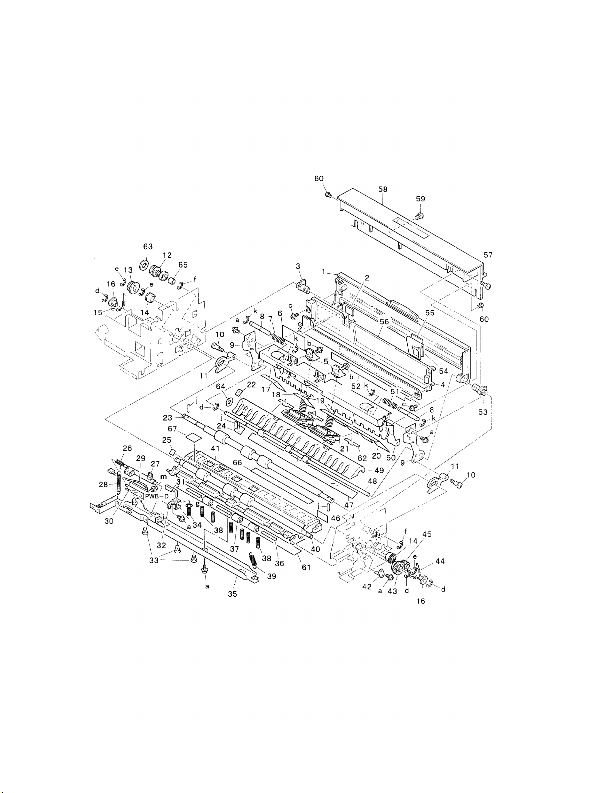
Paper Takeup Section (C) - 1
Page 10 Konica Business Technologies., Inc. Model DF-724
February, 1999 1st Edition
Page 93

REF. PART NUMBER DESCRIPTION
NO.
1 11UP45340 Tray
2 11UP45350 Plate
3 11UP75060 Bushing
4 11UP45360 Guide
5 11UP45370 Holder
6 11UP45380 Label
7 11UP45390 Pressure spring
8 11UP45400 Shaft
9 11UP45410 Support plate
10 11UP45420 Shoulder screw
11 11UP45430 Hinge
12 11UP76550 Pulley
13 11UP76560 Pulley (Z=20)
14 25TU75440 Ball bearing
15 11UP45440 Tension spring
16 11UP75070 Bushing
17 11UP45450 Polyester film
18 11UP45460 Polyester film
19 11UP45470 Pressure spring
20 11UP45480 Polyester film
21 11UP45490 Separator pad
22 11UP45500 Polyester film
23 11UP45510 Roller
24 11UP45520 Polyester film
25 11UP45530 Seal
26 11UP45540 Torsion spring
27 11UP45550 Lever
28 11UP45560 Tension spring
29 11UP-9050 PW board (D)
30 11UP45570 Polyester film
HARDWARE
REF.
LTR.
PART
NUMBER
a 25TU02410
b 25TU01450
c 25TU02210
d 11UP03630
e 11UP03670
f 11UP03640
g 11UP03660
j 25TU01230
k 25TU03620
m 25TU01440
Model DF-724 Konica Business Technologies., Inc. Page 11
1st Edition February, 1999
Page 94

Paper Takeup Section (C) - 2
Page 12 Konica Business Technologies., Inc. Model DF-724
February, 1999 1st Edition
Page 95

REF. PART NUMBER DESCRIPTION
NO.
31 11UP45580 Lever
32 11UP45590 Holder
33 11UP45600 Spacer
34 11UP45610 Pressure spring
35 11UP45620 Bracket
36 11UP45630 Shaft
37 11UP45640 Roller
38 11UP45650 Pressure spring
39 11UP45660 Tension spring
40 11UP45670 Roller
41 11UP45680 Guide plate
42 11UP45690 Guide
43 11UP77070 Gear (Z=30)
44 11UP45700 Tension spring
45 11UP77080 Gear (Z=16)
46 11UP97050 Label (F3)
47 11UP45710 Polyester film
48 11UP45720 Roller
49 11UP45730 Guide plate
50 11UP45740 Guide plate
51 11UP45750 Pressure spring
52 11UQ45760 Scale
53 11UP75080 Bushing
54 11UP45770 Regulating plate
55 11UP45780 Pad
56 11UP45790 Tray
57 11UP45800 Shoulder screw
58 11UP45810 Cover
59 11UP45820 Magnet
60 11UP45830 Shoulder screw
61 11UP45840 Polyester film
62 11UP45850 Polyester film
63 11UP45860 Flange
64 11UP45870 Washer
65 11UP45880 Spacer
66 11UP45890 Polyester film
67 11UP45900 Polyester film
HARDWARE
REF.
LTR.
a 25TU02410
b 25TU01450
c 25TU02210
d 11UP03630
e 11UP03670
f 11UP03640
g 11UP03660
j 25TU01230
k 25TU03620
m 25TU01440
PART
NUMBER
Model DF-724 Konica Business Technologies., Inc. Page 13
1st Edition February, 1999
Page 96

Paper Transport Section
Page 14 Konica Business Technologies., Inc. Model DF-724
February, 1999 1st Edition
Page 97

REF. PART NUMBER DESCRIPTION
NO.
1 12ZL11450 Transport
2 12ZL11460 Spacer
3 12ZL75080 Ball bearing
4 12ZL11470 Plate
5 12ZL11480 Guide
6 12ZL11490 Rear frame
7 12ZL11500 Shoulder screw
8 12ZL11640 Pressure spring
9 12ZL11630 Reinforce plate
10 12ZL11650 Arm
11 12ZL11570 Roll
12 11UP45920 Roller
13 12ZL11540 Reinforce plate
14 12ZL11510 Bracket
15 12ZL11520 Tension (B) spring
16 12ZL75090 Bushing
17 12ZL11580 Roller
18 12ZL11530 Guide
19 12ZL11550 Tension spring
20 12ZL11560 Arm
21 11UP45930 Roller
22 11UP45940 Frame
23 12ZL11590 Bracket
24 12ZL11600 Stopper ring
25 11UP45950 Bracket
26 11UP45960 Magnet catch
27 11UP10230 Shoulder screw
28 11UP45980 Bracket
29 12ZL75070 Ball bearing
30 11UP77090 Gear (Z=23)
HARDWARE
REF.
LTR.
PART
NUMBER
a 25TU02640
b 25TU01520
c 25TU01450
d 11UP01520
e 25TU03630
f 11UM03510
g 25TU01250
Model DF-724 Konica Business Technologies., Inc. Page 15
1st Edition February, 1999
Page 98

Exit Section (A)
Page 16 Konica Business Technologies., Inc. Model DF-724
February, 1999 1st Edition
Page 99

REF. PART NUMBER DESCRIPTION
NO.
1 11UP46010 Rear frame
2 11UP46020 Bracket
3 11UP46030 Ground plate
4 11UP46040 Pin
5 11UP46050 Cover
6 11UP46060 Pressure spring
7 11UP46070 Shaft
8 11UP46080 Neutralizing brush
9 11UP46090 Roller
10 11UP46100 Shaft
11 11UP46110 Plate spring
12 11UP46120 Polyester film
13 11UP46130 Guide
14 11UP45530 Seal
15 11UP46150 Guide plate
16 11UP46160 Roller
17 11UP46170 Plate spring
18 11UP46180 Roller
19 11UP46190 Rubber foot
20 11UP46200 Axle plate
21 11UP46210 Magnet
22 11UP46220 Holder
23 11UP46230 Front frame
24 11UP46240 Bracket
25 11UP46250 Collar
26 11UP46260 Polyester film
27 11UP46270 Rubber strip
28 11UP46280 Plate
29 11UP46290 Bracket
30 11UP46300 Lever
HARDWARE
REF.
LTR.
PART
NUMBER
a 25TU02410
b 25TU02450
c 25TU02640
d 25TU02430
e 25TU02210
f 25TU01880
g 25TU01710
h 11UP03520
j 11UM01260
k 11UP03610
Model DF-724 Konica Business Technologies., Inc. Page 17
1st Edition February, 1999
Page 100

Exit Section (B)
Page 18 Konica Business Technologies., Inc. Model DF-724
February, 1999 1st Edition
 Loading...