

Konica Minolta DF-612, MS-501, SP-503 Service Manual

DF-612 SP-503 MS-501
Option Printer
SERVICE MANUAL
Code Y109850-7

PUBLICATION ISSUED BY:
Olivetti S.p.A.
77, Via Jervis - 10015 Ivrea (TO)
Italy
Copyright © 2008, Olivetti
All rights reserved

Revision history
After publication of this service manual, the parts and mechanism may be subject to change for
improvement of their performance.
Therefore, the descriptions given in this service manual may not coincide with the actual machine.
When any change has been made to the descriptions in the service manual, a revised version will be
issued with a revision mark added as required.
Revision mark:
• To indicate clearly a section revised, is shown at the left margin of the revised section.
The number inside represents the number of times the revision has been made.
• To indicate clearly a page that contains the revision, is shown near the page number of the
corresponding page.
The number inside represents the number of times the revision has been made.
NOTE
Revision marks shown in a page are restricted only to the latest ones with the old ones deleted.
• When a page revised in Ver. 2.0 has been changed in Ver. 3.0:
The revision marks for Ver. 3.0 only are shown with those for Ver. 2.0 deleted.
• When a page revised in Ver. 2.0 has not been changed in Ver. 3.0:
The revision marks for Ver. 2.0 are left as they are.
1
1
1
1

DF-612/SP-503/MS-501Outline
MaintenanceAdjustment / Setting
Troubleshooting
Field Service Ver. 1.0 Jun. 2008
CONTENTS
DF-612/SP-503/MS-501
Outline
1. Product specification ............................................................................................... 1
Maintenance
2. Periodical check ...................................................................................................... 5
2.1 Maintenance procedure (Periodical check parts) ................................................. 5
2.1.1 Separation roller............................................................................................ 5
2.1.2 Feed roller/pick-up roller ............................................................................... 8
2.1.3 Regist rollers/exit rollers................................................................................ 9
3. Other ..................................................................................................................... 10
3.1 Disassembly/adjustment prohibited items .......................................................... 10
3.2 Disassembly/Assembly/Cleaning list (other parts).............................................. 11
3.2.1 Disassembly/Assembly parts list................................................................. 11
3.2.2 Cleaning parts list ....................................................................................... 11
3.3 Disassembly/Assembly procedure...................................................................... 12
3.3.1 Front cover .................................................................................................. 12
3.3.2 Rear cover/Rear left cover/Rear lower cover .............................................. 13
3.3.3 Document feed tray rear cover.................................................................... 14
3.3.4 Auto document feeder tray.......................................................................... 15
3.3.5 Document feed tray..................................................................................... 16
3.3.6 ADF scanner assy....................................................................................... 17
3.3.7 Feed roller/pick-up roller ............................................................................. 19
3.3.8 Transport roller 1, 2 ..................................................................................... 23
3.3.9 DF control board (DFCB) ............................................................................ 24
3.3.10 Print lamp board (PLB) ............................................................................... 24
3.3.11 Take-up motor (M1)..................................................................................... 25
3.3.12 Transport motor (M2) .................................................................................. 25
3.3.13 Cooling fan (FM1) ....................................................................................... 27
3.3.14 Stamp unit ................................................................................................... 28
3.3.15 Spare TX Marker Stamp 2 .......................................................................... 29
3.4 Cleaning procedure ............................................................................................ 30
3.4.1 White sheet ................................................................................................. 30
3.4.2 Registration sensor ..................................................................................... 30
3.4.3 Black sheet (ADF glass assy) ..................................................................... 31
Y109850-7 Service Manual i

DF-612/SP-503/MS-501
Outline
MaintenanceAdjustment / Setting
Troubleshooting
Field Service Ver. 1.0 Jun. 2008
Adjustment/Setting
4. How to use the adjustment section ....................................................................... 33
5. Service Mode ........................................................................................................ 34
5.1 Service Mode setting procedure......................................................................... 34
5.2 ADF Adjustment ................................................................................................. 34
5.2.1 Zoom........................................................................................................... 34
5.2.2 Feed............................................................................................................ 35
5.2.3 Regist Loop................................................................................................. 37
5.2.4 Erasure Width ............................................................................................. 37
5.2.5 Paper Passage ........................................................................................... 38
5.3 Sensor Check (Scan) ......................................................................................... 39
5.3.1 ADF............................................................................................................. 39
6. Mechanical adjustment ......................................................................................... 40
6.1 Adjusting skew feed............................................................................................ 40
Troubleshooting
7. Jam display ........................................................................................................... 43
7.1 Initial check items ............................................................................................... 43
7.2 Misfeed display................................................................................................... 43
7.2.1 Misfeed display resetting procedure ........................................................... 43
7.3 Sensor layout...................................................................................................... 44
7.4 Solution .............................................................................................................. 44
7.4.1 Turnover section misfeed............................................................................ 44
7.4.2 Paper feed section misfeed......................................................................... 45
7.4.3 Transport section misfeed........................................................................... 45
7.4.4 Paper exit section misfeed .......................................................................... 46
7.4.5 Image reading section misfeed ................................................................... 46
ii Service Manual Y109850-7

Field Service Ver. 1.0 Jun. 2008 1. Product specification
DF-612/SP-503/MS-501Outline
Outline
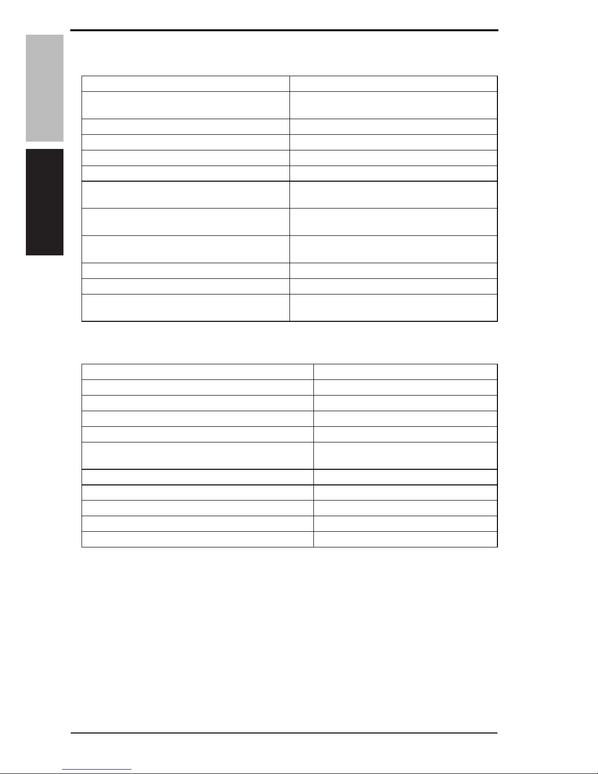
1. Product specification
A. Type
B. Functions
C. Paper type
*1: For the combined original detection mode, refer to the mixed original detection enabled
size combination table.
Name Reverse automatic document feeder
Type Image reading section Sheet-through system
Turnover section Switchback system
Exit section Straight exit system
Installation Screw cramp to the main unit
Document alignment Center
Document loading Face up
Mode Standard mode, Mixed original detection mode, FAX mode
Document feed speed Copy 1-sided mode: 20 pages/min
2-sided mode: 10 pages/min
Color scan
(300 dpi)
1-sided mode: 20 pages/min
2-sided mode: 10 pages/min
Monochrome scan
(300 dpi)
1-sided mode: 40 pages/min
2-sided mode: 20 pages/min
Type of document Standard mode
Plain paper
1-sided mode
38 to 128 g/m
2
(10 to 34 lb)
2-sided mode
50 to 128 g/m
2
(13.25 to 34 lb)
Mixed original detection mode
Plain paper
1-sided / 2-sided mode
50 to 128 g/m
2
(13.25 to 34 lb)
FAX mode
Plain paper
1-sided mode
38 to 128 g/m
2
(10 to 34 lb)
2-sided mode
50 to 128 g/m
2
(13.25 to 34 lb)
Detectable document
size*1
(Standard mode,
FAX mode)
Metric area A5, A5S, B5, B5S, A4, A4S, B4, A3,
5
1
/2 x 8 1/2, 5 1/2 x 8 1/2S, FLS
(China only: 8K, 16K, 16KS)
Inch area 5
1
/2 x 8 1/2S, 8 1/2 x 11, 8 1/2 x 11S,
8
1
/2 x 14, 11 x 17, A4
Capacity 70 sheets (80 g/m
2
)
Y109850-7 Service Manual 1
1. Product specification Field Service Ver. 1.0 Jun. 2008
DF-612/SP-503/MS-501
Outline
D. Paper feed prohibited originals
• If fed, trouble occurrence will be highly possible.
E. Paper feed not guaranteed originals
• If fed, paper feed will be possible to some extent but trouble occurrence will be possible.
Type of original Possible trouble
Sheets stapled or clipped together Paper feed failure, damaged sheet, defective drive
mechanism due to jammed staples or clips
Book original Paper feed failure, damaged sheet
Sheets glued together Paper feed failure, damaged sheet
Sheets clipped or notched Damaged sheet, transport failure
Sheets patched Patched part folded or torn sheet
Sheets folded, torn or wrinkled Paper feed failure, damaged sheet,
transport failure
Original weighing less than 38 g/m
2
(10 lb) or
128 g/m
2
(34 lb) or more
Paper feed failure, transport failure
Sheets severely curled (15 mm or more) Sheets misfed due to being dog-eared or fed in
askew
OHP film (Transparency film) Paper feed failure, transport failure
Label paper Paper feed failure, transport failure
Glossy photographic paper or glossy enamel
paper
Transport failure, damaged sheet
Type of Original Possible Trouble
Sheets lightly curled (Curled amount: 10 to 15 mm) Dog-eared, exit failure, transport failure
Heat sensitive paper Edge folded, exit failure, transport failure
Intermediate paper Paper feed failure, transport failure
Paper immediately after paper exit from the main unit Paper feed failure, transport failure
Paper with many punched holes (e.g., loose leaf) limited
to vertical feeding
Multi-page feed due to flashes from holes
Sheets two-folded or Z-folded Transport failure, image deformation
Sheets with 2 to 4 holes Transport failure
Ink jet paper Paper feed failure, transport failure
Sheets with smooth surface (Coated paper) Paper feed failure, transport failure
Sheets with rough surface (e.g., letterhead) Paper feed failure
2 Service Manual Y109850-7

Field Service Ver. 1.0 Jun. 2008 1. Product specification
DF-612/SP-503/MS-501Outline
F. Mixed original feed chart
For metric
For inch
G. Machine specifications
H. Operating environment
Conforms to the operating environment of the main unit.
NOTE
• These specifications are subject to change without notice.
Max. original
size
297 mm 257 mm 210 mm 182 mm 148 mm
Mixed original size A3 A4 B4 B5 A4S A5 B5S A5S
297 mm
A3 OKOK------
A4 OKOK------
257 mm
B4 xxOKOK----
B5 xxOKOK----
210 mm
A4S xxxxOKOK- -
A5 xxxxOKOK- -
182 mm B5S xxxxxxOK-
148 mm A5S xxxxxxxOK
Max. original
size
11
8
1
/
2
51/
2
Mixed original size 11 x 17
8
1
/2 x 11 8 1/2 x 14 8 1/2 x 11S 5 1/2 x 8 1/251/2 x 8 1/2S
11
11 x 17 OK OK - - - -
8
1
/2 x 11
OK OK - - - -
8
1
/
2
81/2 x 14
x x OK OK OK -
8
1
/2 x 11S
x x OK OK OK -
5
1
/2 x 8 1/
2
x x OK OK OK -
5
1
/
2
51/2 x 8 1/2S
xx x x x OK
OK Mixed original feed available
x No. mixed original feed
- Can not set original
Power requirements DC 24 V (supplied from the main unit)
Max. power consumption 55 W or less
Dimensions 551 mm (W) x 511 mm (D) x 118 mm (H)
21.7 inch (W) x 20.1 inch (D) x 4.7 inch (H)
Weight 8.1 kg (17.85 lb)
Y109850-7 Service Manual 3

1. Product specification Field Service Ver. 1.0 Jun. 2008
DF-612/SP-503/MS-501
Outline
Blank Page
4 Service Manual Y109850-7
Field Service Ver. 1.0 Jun. 2008 2. Periodical check
DF-612/SP-503/MS-501
Maintenance
Maintenance
2. Periodical check
2.1 Maintenance procedure (Periodical check parts)
NOTE
• The alcohol described in the cleaning procedure of maintenance represents the
isopropyl alcohol.
2.1.1 Separation roller
A. Periodically cleaning parts/cycle
• Separation roller: Every 30,000 originals feed
B. Periodically replaced parts/cycle
• Separation roller: Every 100,000 originals feed
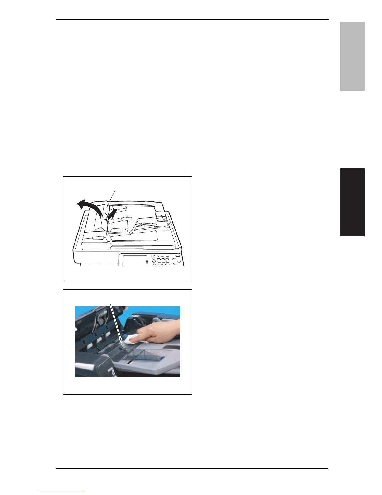
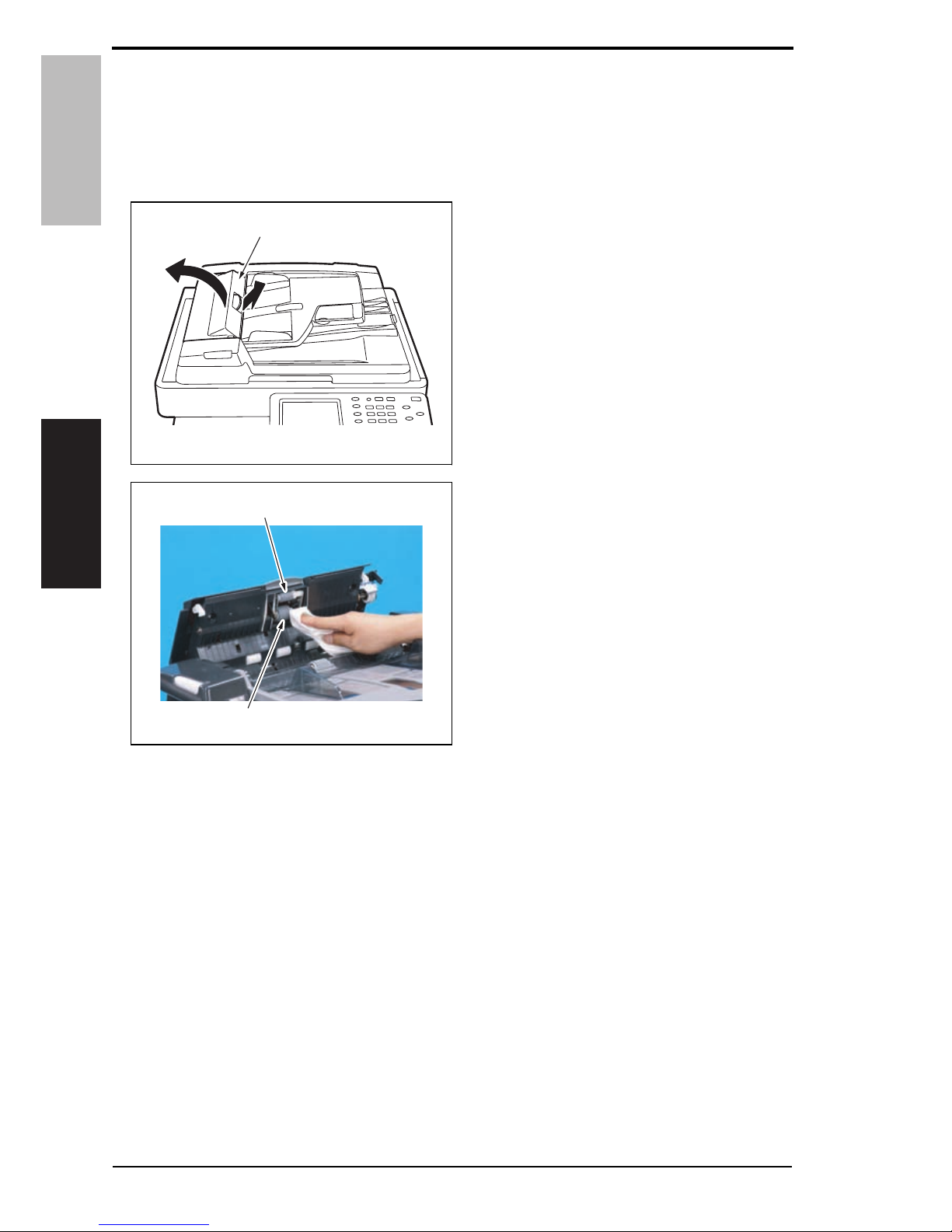
C. Cleaning procedure
1. Open the feed cover [1].
2. Using a cleaning pad dampened with
alcohol, wipe the separation roller [1]
clean of dirt.
A0EYF2C500DA
[1]
A0EYF2C001DA
[1]
Y109850-7 Service Manual 5
2. Periodical check Field Service Ver. 1.0 Jun. 2008
DF-612/SP-503/MS-501
Maintenance
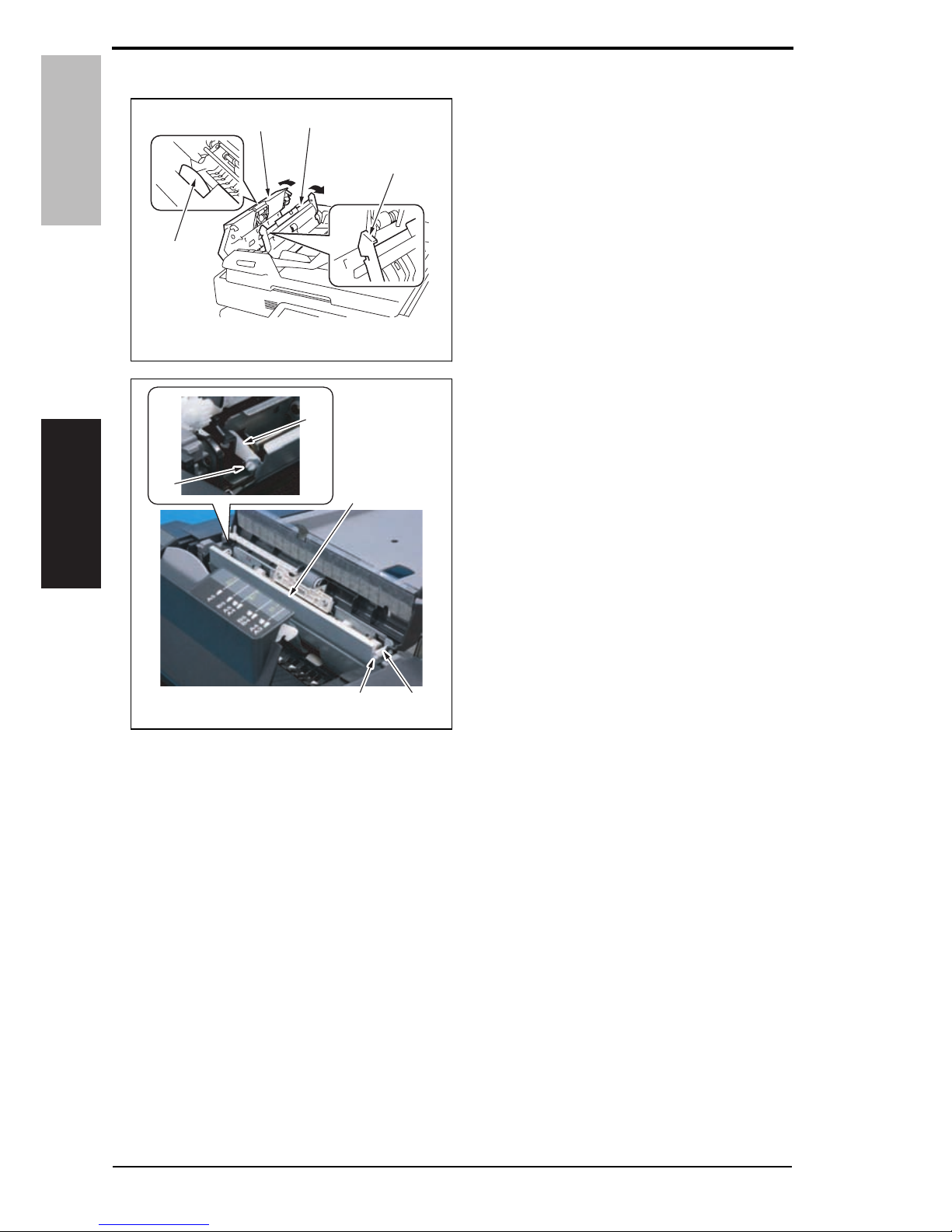
D. Replacing procedure
1. Pull the lever [1] to open the feed
cover [2].
2. Raise the knob [3] and open the document guide [4].
3. Unhook the tab [1] and remove the
two arms [2].
4. Open the frame [3].
A0EYF2C511DA
[1]
[2]
[4]
[3]
A0EYF2C002DA
[1]
[1]
[2]
[2]
[3]
6 Service Manual Y109850-7
Field Service Ver. 1.0 Jun. 2008 2. Periodical check
DF-612/SP-503/MS-501
Maintenance
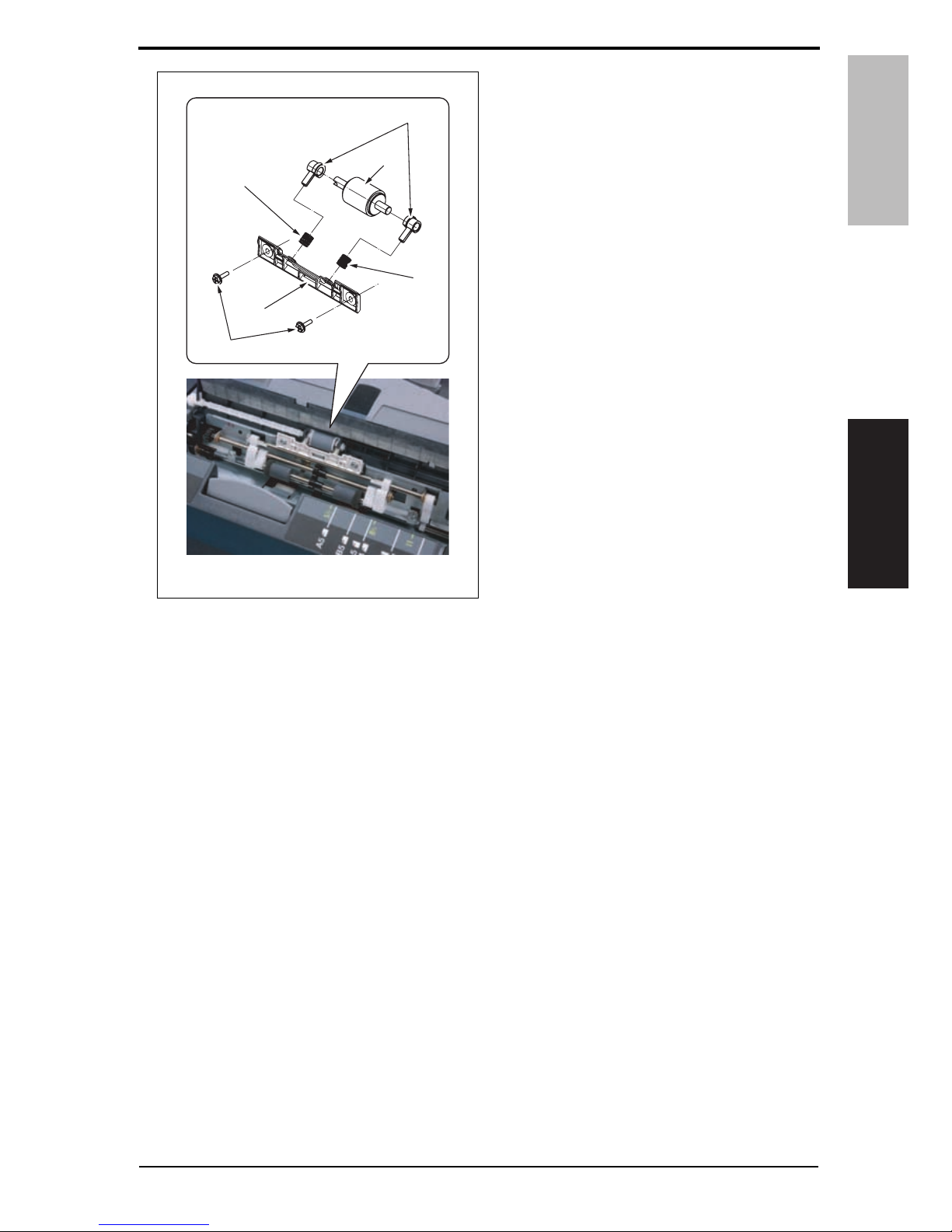
5. Remove two screws [1] and the plate
[2].
6. Remove two springs [3], two bearing
splits [4], and the separator roller [5].
A0EYF2C003DA
[1]
[2]
[3]
[3]
[5]
[4]
Y109850-7 Service Manual 7
2. Periodical check Field Service Ver. 1.0 Jun. 2008
DF-612/SP-503/MS-501
Maintenance
2.1.2 Feed roller/pick-up roller
A. Periodically cleaning parts/cycle
• Feed roller: Every 30,000 originals feed
• Pick-up roller: Every 30,000 originals feed
B. Cleaning procedure
1. Open the feed cover [1].
2. Using a cleaning pad dampened with
alcohol, wipe the feed roller [1]/pickup roller [2] clean of dirt.
A0EYF2C500DA
[1]
A0EYF2C004DA
[2]
[1]
8 Service Manual Y109850-7
Field Service Ver. 1.0 Jun. 2008 2. Periodical check
DF-612/SP-503/MS-501
Maintenance
2.1.3 Regist rollers/exit rollers
A. Periodically cleaning parts/cycle
• Regist rollers: Every 30,000 originals feed
• Exit rollers: Every 30,000 originals feed
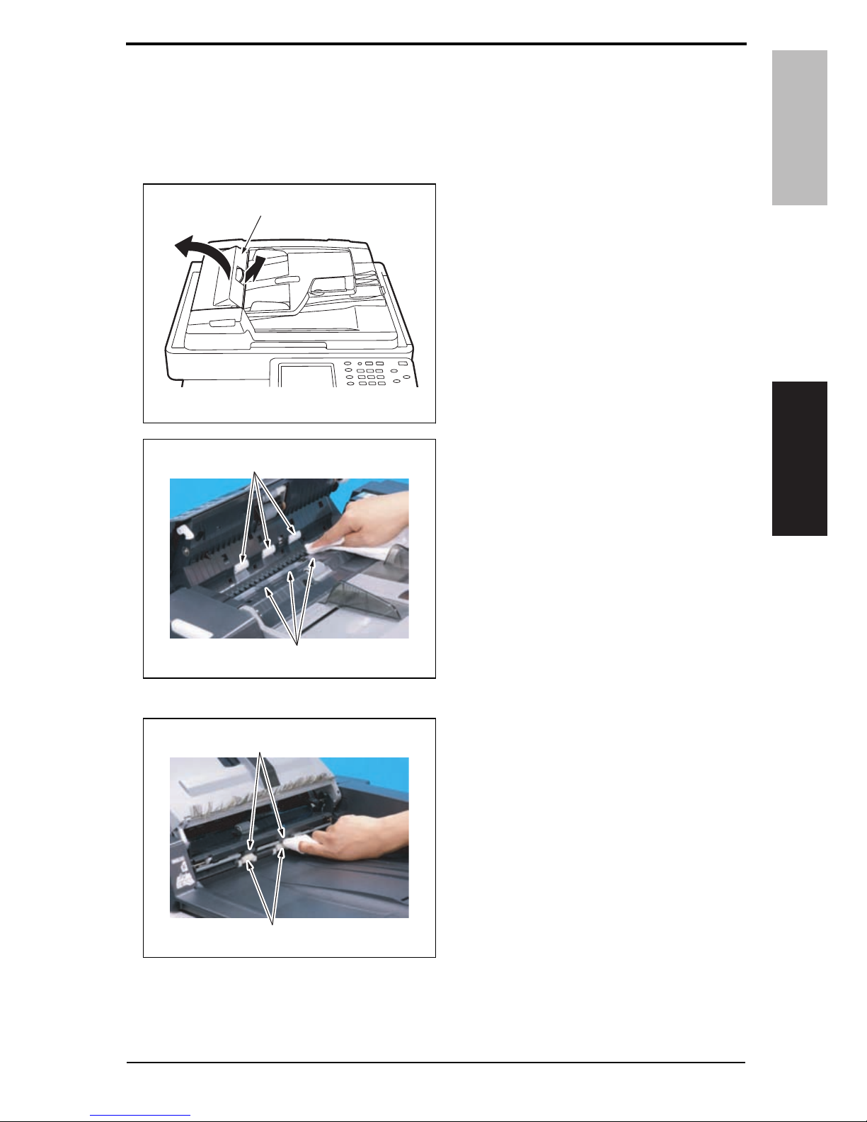
B. Cleaning procedure
1. Open the feed cover [1].
2. Using a cleaning pad dampened with
alcohol, wipe three regist rollers [1]
and three rolls [2] clean of dirt.
3. Lift up the document feed tray.
4. Using a cleaning pad dampened with
alcohol, wipe two exit rollers [1] and
two rolls [2] clean of dirt.
A0EYF2C500DA
[1]
A0EYF2C042DA
[1]
[2]
A0EYF2C043DA
[1]
[2]
Y109850-7 Service Manual 9

3. Other Field Service Ver. 1.0 Jun. 2008
DF-612/SP-503/MS-501
Maintenance
3. Other
3.1 Disassembly/adjustment prohibited items
A. Paint-locked screws
NOTE
• To prevent loose screws, a screw lock in blue or green series color is applied to
the screws.
• The screw lock is applied to the screws that may get loose due to the vibrations
and loads created by the use of machine or due to the vibrations created during
transportation.
• If the screw lock coated screws are loosened or removed, be sure to apply a screw
lock after the screws are tightened.
B. Red-painted screws
NOTE
• The screws which are difficult to be adjusted in the field are painted in red in order
to prevent them from being removed by mistake.
• Do not remove or loosen any of the red-painted screws in the field. It should also
be noted that, when two or more screws are used for a single part, only one representative screw may be marked with the red paint.
C. Variable resistors on board
NOTE
• Do not turn the variable resistors on boards for which no adjusting instructions
are given in Adjustment/Setting.
D. Removal of PWBs
CAUTION
• When removing a circuit board or other electrical component, refer to “Handling of
PWBs” and follow the corresponding removal procedures.
• The removal procedures given in the following omit the removal of connectors and
screws securing the circuit board support or circuit board.
• Where it is absolutely necessary to touch the ICs and other electrical components
on the board, be sure to ground your body.
10 Service Manual Y109850-7
Field Service Ver. 1.0 Jun. 2008 3. Other
DF-612/SP-503/MS-501
Maintenance
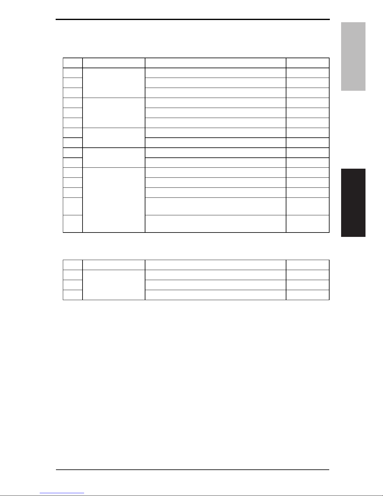
3.2 Disassembly/Assembly/Cleaning list (other parts)
3.2.1 Disassembly/Assembly parts list
3.2.2 Cleaning parts list
No. Section Part name Ref. page
1
Exterior parts
Front cover P. 1 2
2 Rear cover/Rear left cover/Rear lower cover P. 1 3
3 Document feed tray rear cover P. 1 4
4
Units
Auto document feeder unit P. 1 5
5 Document feed tray P. 1 6
6 ADF scanner assy P. 1 7
7
Rollers
Feed roller/Pick-up roller P. 1 9
8 Transport roller 1, 2 P. 2 3
9
PWBs
DF control board (DFCB) P. 2 4
10 Print lamp board (PLB) P. 2 4
11
Others
Take-up motor (M1) P. 2 5
12 Transport motor (M2) P. 2 5
13 Cooling fan (FM1) P. 2 7
14
SP-503
Stamp unit
P. 2 8
15
MS-501
Spare TX Marker Stamp 2
P. 2 9
No. Section Part name Ref. page
1
Transport section
White sheet P. 3 0
2 Registration sensor P. 3 0
3 Black sheet (ADF glass assy) P. 3 1
Y109850-7 Service Manual 11
 Loading...