

Konica Minolta DF-606 Service Manual

SERVICE MANUAL
2005.06
Ver. 1.0
DF-606
Theory of Operation
Revision history
After publication of this service manual, the parts and mechanism may be subject to change for improvement of their performance.
Therefore, the descriptions given in this service manual may not coincide with the actual machine.
When any change has been made to the descriptions in the service manual, a revised version will be
issued with a revision mark added as required.
Revision mark:
• To indicate clearly a section revised, show to the left of the revised section.
A number within represents the number of times the revision has been made.
• To indicate clearly a section revised, show in the lower outside section of the corresponding
page.
A number within represents the number of times the revision has been made.
NOTE
Revision marks shown in a page are restricted only to the latest ones with the old ones deleted.
• When a page revised in Ver. 2.0 has been changed in Ver. 3.0:
The revision marks for Ver. 3.0 only are shown with those for Ver. 2.0 deleted.
• When a page revised in Ver. 2.0 has not been changed in Ver. 3.0:
The revision marks for Ver. 2.0 are left as they are.
1
1
1
1
2005/06 1.0 — Issue of the first edition
Date Service manual Ver. Revision mark Descriptions of revision

DF-606
CONTENTS
i
Theory of Operation Ver1.0 Jun.2005
CONTENTS
DF-606
OUTLINE
1. PRODUCT SPECIFICATIONS . . . . . . . . . . . . . . . . . . . . . . . . . . . . . . . . . . . . . . . . . . . . . . . . . . . . . . . . . . . 1
2. PAPER PATH . . . . . . . . . . . . . . . . . . . . . . . . . . . . . . . . . . . . . . . . . . . . . . . . . . . . . . . . . . . . . . . . . . . . . . . 3
2.1 Single sided original mode . . . . . . . . . . . . . . . . . . . . . . . . . . . . . . . . . . . . . . . . . . . . . . . . . . . . . . . . . 3
2.1.1 Small size. . . . . . . . . . . . . . . . . . . . . . . . . . . . . . . . . . . . . . . . . . . . . . . . . . . . . . . . . . . . . . . . . . 3
2.1.2 Large size . . . . . . . . . . . . . . . . . . . . . . . . . . . . . . . . . . . . . . . . . . . . . . . . . . . . . . . . . . . . . . . . . 3
2.2 Double sided original mode . . . . . . . . . . . . . . . . . . . . . . . . . . . . . . . . . . . . . . . . . . . . . . . . . . . . . . . . . 4
2.2.1 Small size. . . . . . . . . . . . . . . . . . . . . . . . . . . . . . . . . . . . . . . . . . . . . . . . . . . . . . . . . . . . . . . . . . 4
2.2.2 Large size . . . . . . . . . . . . . . . . . . . . . . . . . . . . . . . . . . . . . . . . . . . . . . . . . . . . . . . . . . . . . . . . . 6
2.3 Mixed original mode . . . . . . . . . . . . . . . . . . . . . . . . . . . . . . . . . . . . . . . . . . . . . . . . . . . . . . . . . . . . . . 8
2.3.1 AMS not used . . . . . . . . . . . . . . . . . . . . . . . . . . . . . . . . . . . . . . . . . . . . . . . . . . . . . . . . . . . . . . 8
2.3.2 AMS used (single sided/double sided) . . . . . . . . . . . . . . . . . . . . . . . . . . . . . . . . . . . . . . . . . . . . 8
2.3.3 Z-folding original mode. . . . . . . . . . . . . . . . . . . . . . . . . . . . . . . . . . . . . . . . . . . . . . . . . . . . . . . . 8
COMPOSITION/OPERATION
3. COMPOSITION . . . . . . . . . . . . . . . . . . . . . . . . . . . . . . . . . . . . . . . . . . . . . . . . . . . . . . . . . . . . . . . . . . . . . 9
4. PAPER FEED SECTION . . . . . . . . . . . . . . . . . . . . . . . . . . . . . . . . . . . . . . . . . . . . . . . . . . . . . . . . . . . . . . 10
4.1 Drive . . . . . . . . . . . . . . . . . . . . . . . . . . . . . . . . . . . . . . . . . . . . . . . . . . . . . . . . . . . . . . . . . . . . . . . . . 10
4.1.1 Paper feed drive . . . . . . . . . . . . . . . . . . . . . . . . . . . . . . . . . . . . . . . . . . . . . . . . . . . . . . . . . . . . 10
4.1.2 Tray up/down drive . . . . . . . . . . . . . . . . . . . . . . . . . . . . . . . . . . . . . . . . . . . . . . . . . . . . . . . . . 10
4.2 Operation . . . . . . . . . . . . . . . . . . . . . . . . . . . . . . . . . . . . . . . . . . . . . . . . . . . . . . . . . . . . . . . . . . . . . 11
4.2.1 Size detection control. . . . . . . . . . . . . . . . . . . . . . . . . . . . . . . . . . . . . . . . . . . . . . . . . . . . . . . . 11
4.2.2 Pick-up mechanism . . . . . . . . . . . . . . . . . . . . . . . . . . . . . . . . . . . . . . . . . . . . . . . . . . . . . . . . . 12
4.2.3 Separation mechanism. . . . . . . . . . . . . . . . . . . . . . . . . . . . . . . . . . . . . . . . . . . . . . . . . . . . . . . 13
4.2.4 SDF (single document feeder) control. . . . . . . . . . . . . . . . . . . . . . . . . . . . . . . . . . . . . . . . . . . . 13
4.2.5 Original empty detection control . . . . . . . . . . . . . . . . . . . . . . . . . . . . . . . . . . . . . . . . . . . . . . . . 13
4.2.6 Registration control . . . . . . . . . . . . . . . . . . . . . . . . . . . . . . . . . . . . . . . . . . . . . . . . . . . . . . . . . 13
5. CONVEYANCE SECTION. . . . . . . . . . . . . . . . . . . . . . . . . . . . . . . . . . . . . . . . . . . . . . . . . . . . . . . . . . . . . 14
5.1 Drive . . . . . . . . . . . . . . . . . . . . . . . . . . . . . . . . . . . . . . . . . . . . . . . . . . . . . . . . . . . . . . . . . . . . . . . . . 14
5.1.1 Conveyance drive. . . . . . . . . . . . . . . . . . . . . . . . . . . . . . . . . . . . . . . . . . . . . . . . . . . . . . . . . . . 14
5.1.2 Flapper up/down drive . . . . . . . . . . . . . . . . . . . . . . . . . . . . . . . . . . . . . . . . . . . . . . . . . . . . . . . 14
5.2 Operation . . . . . . . . . . . . . . . . . . . . . . . . . . . . . . . . . . . . . . . . . . . . . . . . . . . . . . . . . . . . . . . . . . . . . 15
5.2.1 Conveyance control . . . . . . . . . . . . . . . . . . . . . . . . . . . . . . . . . . . . . . . . . . . . . . . . . . . . . . . . . 15
5.2.2 Mixed original mode control . . . . . . . . . . . . . . . . . . . . . . . . . . . . . . . . . . . . . . . . . . . . . . . . . . . 15
5.2.3 Z-fold original mode control . . . . . . . . . . . . . . . . . . . . . . . . . . . . . . . . . . . . . . . . . . . . . . . . . . . 15
5.2.4 Skew adjustment control . . . . . . . . . . . . . . . . . . . . . . . . . . . . . . . . . . . . . . . . . . . . . . . . . . . . . 15
5.2.5 Cooling fan control . . . . . . . . . . . . . . . . . . . . . . . . . . . . . . . . . . . . . . . . . . . . . . . . . . . . . . . . . . 15
6. REVERSAL SECTION. . . . . . . . . . . . . . . . . . . . . . . . . . . . . . . . . . . . . . . . . . . . . . . . . . . . . . . . . . . . . . . . 16
6.1 Drive . . . . . . . . . . . . . . . . . . . . . . . . . . . . . . . . . . . . . . . . . . . . . . . . . . . . . . . . . . . . . . . . . . . . . . . . . 16
6.1.1 Reverse drive . . . . . . . . . . . . . . . . . . . . . . . . . . . . . . . . . . . . . . . . . . . . . . . . . . . . . . . . . . . . . . 16
6.1.2 Pressure roller release drive . . . . . . . . . . . . . . . . . . . . . . . . . . . . . . . . . . . . . . . . . . . . . . . . . . . 16
6.2 Operation . . . . . . . . . . . . . . . . . . . . . . . . . . . . . . . . . . . . . . . . . . . . . . . . . . . . . . . . . . . . . . . . . . . . . 17
6.2.1 Reverse mechanism . . . . . . . . . . . . . . . . . . . . . . . . . . . . . . . . . . . . . . . . . . . . . . . . . . . . . . . . . 17
6.2.2 Registration control . . . . . . . . . . . . . . . . . . . . . . . . . . . . . . . . . . . . . . . . . . . . . . . . . . . . . . . . . 19

DF-606
CONTENTS
ii
Theory of Operation Ver1.0 Jun.2005
7. PAPER EXIT SECTION . . . . . . . . . . . . . . . . . . . . . . . . . . . . . . . . . . . . . . . . . . . . . . . . . . . . . . . . . . . . . . . 21
7.1 Drive . . . . . . . . . . . . . . . . . . . . . . . . . . . . . . . . . . . . . . . . . . . . . . . . . . . . . . . . . . . . . . . . . . . . . . . . . 21
7.1.1 Paper exit drive (for large size) . . . . . . . . . . . . . . . . . . . . . . . . . . . . . . . . . . . . . . . . . . . . . . . . . 21
7.1.2 Paper exit drive (for small size) . . . . . . . . . . . . . . . . . . . . . . . . . . . . . . . . . . . . . . . . . . . . . . . . . 21
7.1.3 Exit gate drive. . . . . . . . . . . . . . . . . . . . . . . . . . . . . . . . . . . . . . . . . . . . . . . . . . . . . . . . . . . . . . 22
7.2 Operation . . . . . . . . . . . . . . . . . . . . . . . . . . . . . . . . . . . . . . . . . . . . . . . . . . . . . . . . . . . . . . . . . . . . . 23
7.2.1 Paper exit operation of small size original . . . . . . . . . . . . . . . . . . . . . . . . . . . . . . . . . . . . . . . . . 23
7.2.2 Paper exit operation of large size original . . . . . . . . . . . . . . . . . . . . . . . . . . . . . . . . . . . . . . . . . 25
DF-606
1. PRODUCT SPECIFICATIONS
1
Theory of Operation Ver1.0 Jun.2005
OUTLINE
1. PRODUCT SPECIFICATIONS
A. Type
B. Functions
C. Original
Name Double sided original auto feeder
Type Sheet-through type original auto feeder
Original size Metric: A3, B4, A4, A4R, B5, B5R, A5, A5R, B6R, 11 x 17, 8.5 x 11,
8.5 x 13
Inch: 11 x 17, 8.5 x 14, 8.5 x 11, 8.5 x 11R, 5.5 x 8.5, 5.5 x 8.5R, A3,
B4, A4, B5, B5R, A5, A5R, B6R
Taiwan spec: A3, A4, A4R, A5, A5R, 8K, 16K, 16KR
Maximum original size: 297 x 431.8 mm
Minimum original size: 128 x 139.7 mm
Original stacking capacity 100 sheets, max. (80g/m
2
or 20 lbs)
Original read speed (A4
size)
Single sided copy mode: 92 sheets/min.
Double sided copy mode: 65 sheets/min.
Original feed layout Set with the front side up, at center as standard
Original image read position Dedicated slit glass section
Resolution 600 dpi
Type of paper High-quality paper of 50 to 130 g/m
2
In the case of the single sided original mode, however, high-quality paper of
131 to 200 g/m
2
is also available.
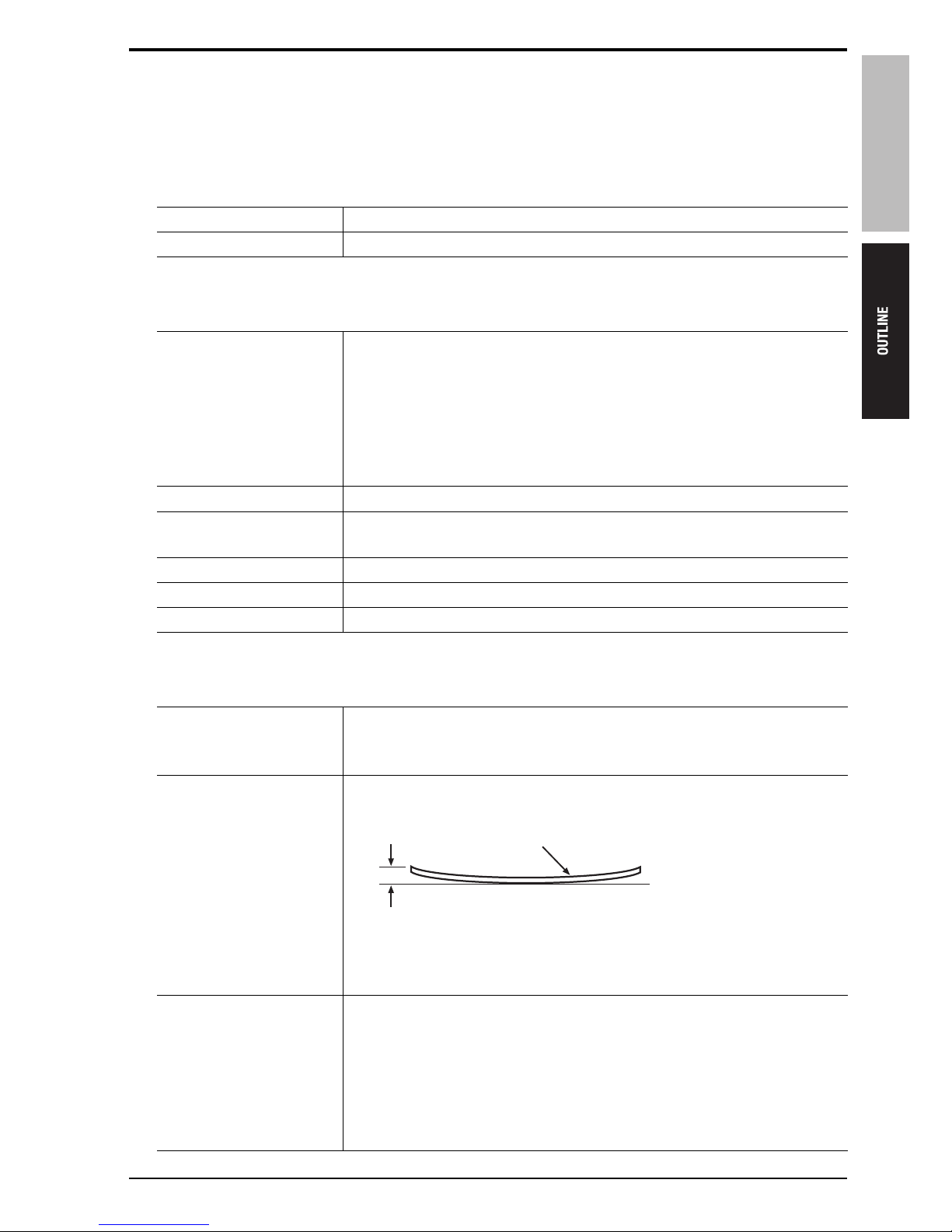
Amount of curling Up to 10 mm with 5 originals overlapped one another
a Amount of curling: up to 10 mm
[1] Original
Originals other than those
that paper feed and
throughput can be guaranteed
With the following originals, no severe problems are found such as frequent jams
and major damage to the originals, although it is not possible to obtain a numeric
value indicating reliability that can be specified in product guarantee terms:
Recycled paper, straw paper, heat sensitive paper, originals fed in the mixing
of perforated original mode, high-quality paper of 35 to 50 g/m
2
, irregularsized originals (such as CF originals), coated paper, originals with a rough
surface (such as letterhead), folded originals (Z-folded or folded in two)
15sat1c001na
[1]
a
1. PRODUCT SPECIFICATIONS
2
Theory of Operation Ver1.0 Jun.2005
DF-606
Note
• The information herein may be subject to change for improvement without notice.
D. Maintenance
E. Machine data
F. Operating environment
Originals not allowed to be
fed
The following originals are not allowed to be used:
OHP film, blueprint master, label paper, offset master, bonded original,
high-quality paper of less than 35 g/m
2
or more than 201 g/m2
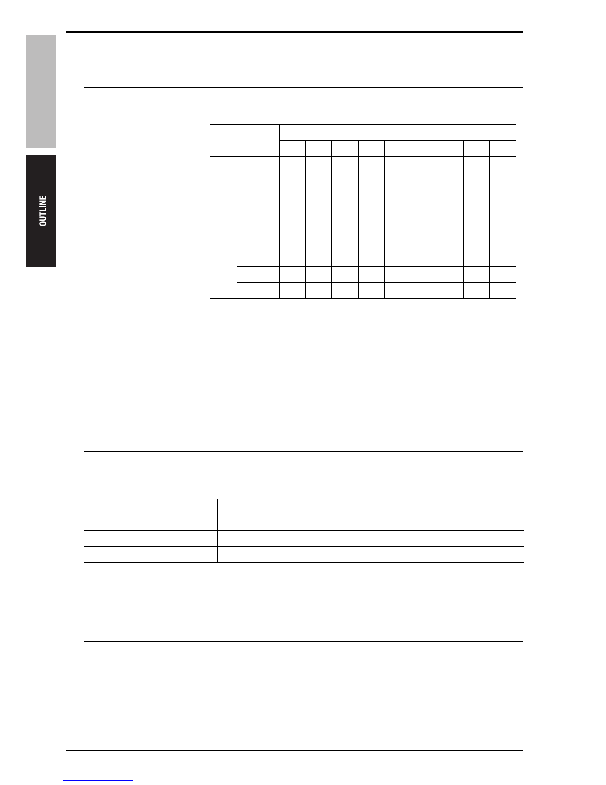
Combination of mixed originals
Combinations of the same and different size originals is available. The following
table shows the available combination of mixed originals.
Maintenance Same as the main body.
Machine service life Same as the main body.
Power source 24V/5.1V DC (supplied from the main body)
Maximum power consumption 210W or less
Dimensions 650 (W) x 570 (D) x 170 (H) mm
Weight Approx. 22kg
Temperature 10 to 30°C
Humidity 10 to 80% RH (with no condensation)
Reference original (original with a maximum width)
A3 A4 B4 B5 A4R A5 B5R A5R B6R
Other
origi-
nals
A3 U { ———————
A4 { U ———————
B4 ~ ~ U { —————
B5 ~ ~ { U —————
A4R ~ ~ ~ ~ U { ———
A5 ~ ~ ~ ~ { U ———
B5R X X ~ ~ ~ ~ U ——
A5R X X X X X X X U —
B6R X X X X X X X ~ U
U: Single size {: Same size ~: Different size X: Mixing not allowed
—: Cannot be set
DF-606
2. PAPER PATH
3
Theory of Operation Ver1.0 Jun.2005
2. PAPER PATH
2.1 Single sided original mode
2.1.1 Small size
2.1.2 Large size
[1] Original feed tray [3] Exit gate
[2] Original exit tray (for small size) [4] Image read position (slit glass section)
[1] Original feed tray [3] Exit roller
[2] Original exit tray (for large size) [4] Image read position (slit glass section)
15sat1c002na
[3]
[2]
[4]
[1]
15sat1c003na
[3]
[2]
[4]
[1]
2. PAPER PATH
4
Theory of Operation Ver1.0 Jun.2005
DF-606
2.2 Double sided original mode
2.2.1 Small size
A. Front scan
B. Rear scan 1
[1] Original feed tray [3] Exit gate
[2] Original exit tray (for small size) [4] Image read position (slit glass section)
[1] Original feed tray [3] Exit gate
[2] Original exit tray (for small size) [4] Image read position (slit glass section)
15sat1c004na
[1]
[3]
[4]
[2]
15sat1c005na
[3][4]
[2]
[1]
1
2
DF-606
2. PAPER PATH
5
Theory of Operation Ver1.0 Jun.2005
C. Rear scan 2
D. Paper exit
[1] Original feed tray [3] Exit gate
[2] Original exit tray (for small size) [4] Image read position (slit glass section)
[1] Original feed tray [3] Exit gate
[2] Original exit tray (for small size)
15sat1c006na
[3][4]
[2]
[1]
3
15sat1c007na
[3]
[2]
[1]
2. PAPER PATH
6
Theory of Operation Ver1.0 Jun.2005
DF-606
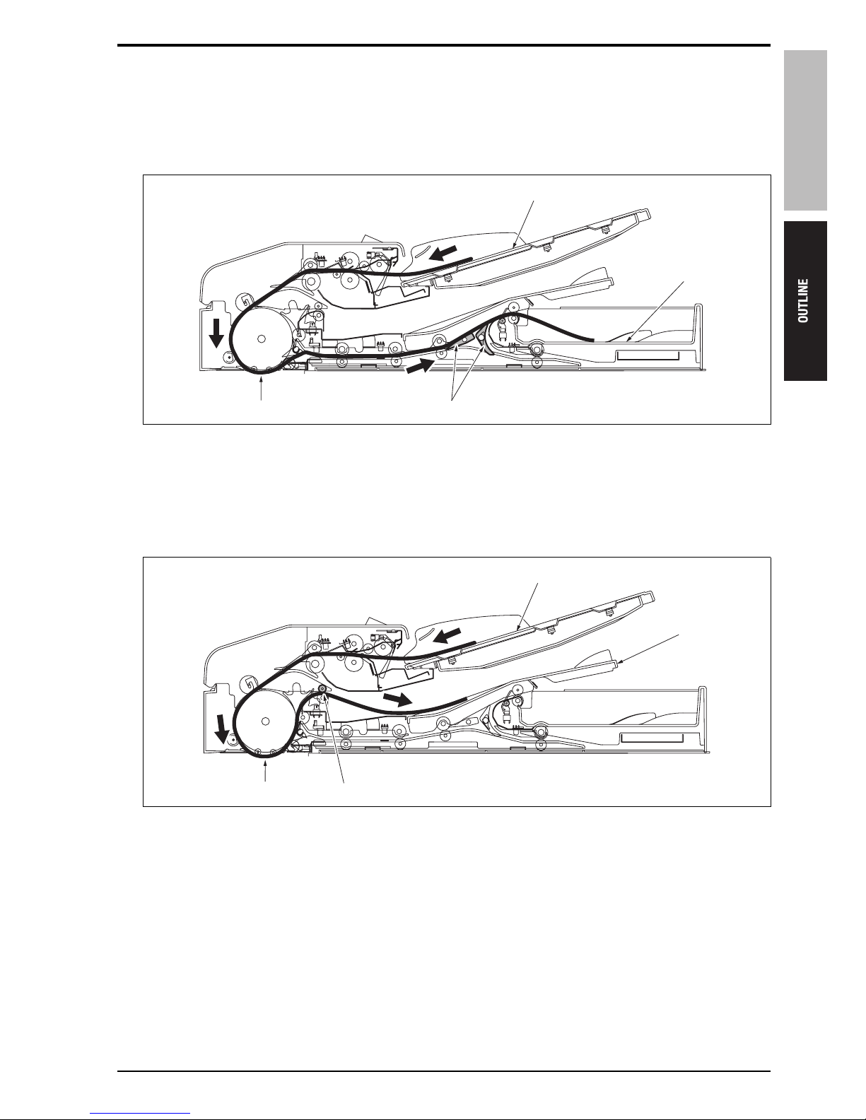
2.2.2 Large size
A. Front scan
B. Rear scan 1
[1] Original feed tray [3] Exit gate
[2] Original exit tray (for large size) [4] Image read position (slit glass section)
[1] Original feed tray [3] Exit gate
[2] Original exit tray (for large size) [4] Image read position (slit glass section)
15sat1c008na
[3][4]
[2]
[1]
15sat1c009na
[3][4]
[2]
[1]
1
2
DF-606
2. PAPER PATH
7
Theory of Operation Ver1.0 Jun.2005
C. Rear scan 2
D. Paper exit
[1] Original feed tray [3] Exit gate
[2] Original exit tray (for large size) [4] Image read position (slit glass section)
[1] Original feed tray [3] Exit gate
[2] Original exit tray (for large size) [4] Exit roller
15sat1c010na
[3][4]
[2]
[1]
3
15sat1c011na
[3][4]
[2]
[1]

2. PAPER PATH
8
Theory of Operation Ver1.0 Jun.2005
DF-606
2.3 Mixed original mode
2.3.1 AMS not used
Single sided original mode: same as the normal single sided original mode
Double sided original mode: same as the normal double sided original mode
2.3.2 AMS used (single sided/double sided)
In the mixed original copy mode, the size detection of originals in the sub scan direction is made according to
the ON time period of the original registration sensor (PS306). Accordingly, the size detection operation is made
prior to the scan operation.
Operations after that are as shown below.
Single sided original mode: same as the normal single sided original mode
Double sided original mode: same as the normal double sided original mode
For particulars of the size detection control, see "4.2.1 Size detection control B. Mixed original mode."
2.3.3 Z-folding original mode
In the Z-fold original mode, in the same manner as the mixed original copy mode, the size detection of originals
in the sub scan direction is made only on the first sheet of paper according to the ON time period of the original
registration sensor (PS306). Accordingly, the size detection operation is made prior to the scan operation.
Operations after that are as shown below.
Single sided original mode: same as the normal single sided original mode
Double sided original mode: same as the normal double sided original mode
For particulars of the size detection control, see "4.2.1 Size detection control B. Mixed original mode."
DF-606
3. COMPOSITION
9
Theory of Operation Ver1.0 Jun.2005
COMPOSITION/OPERATION
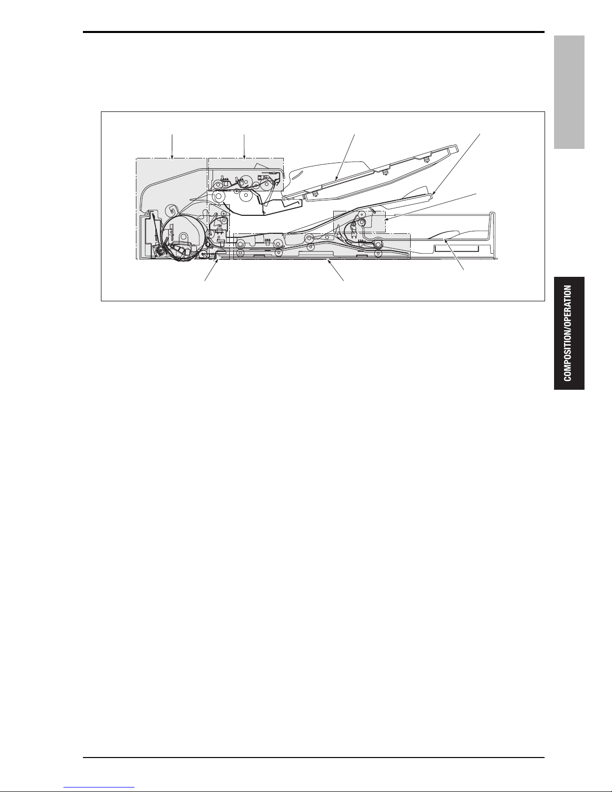
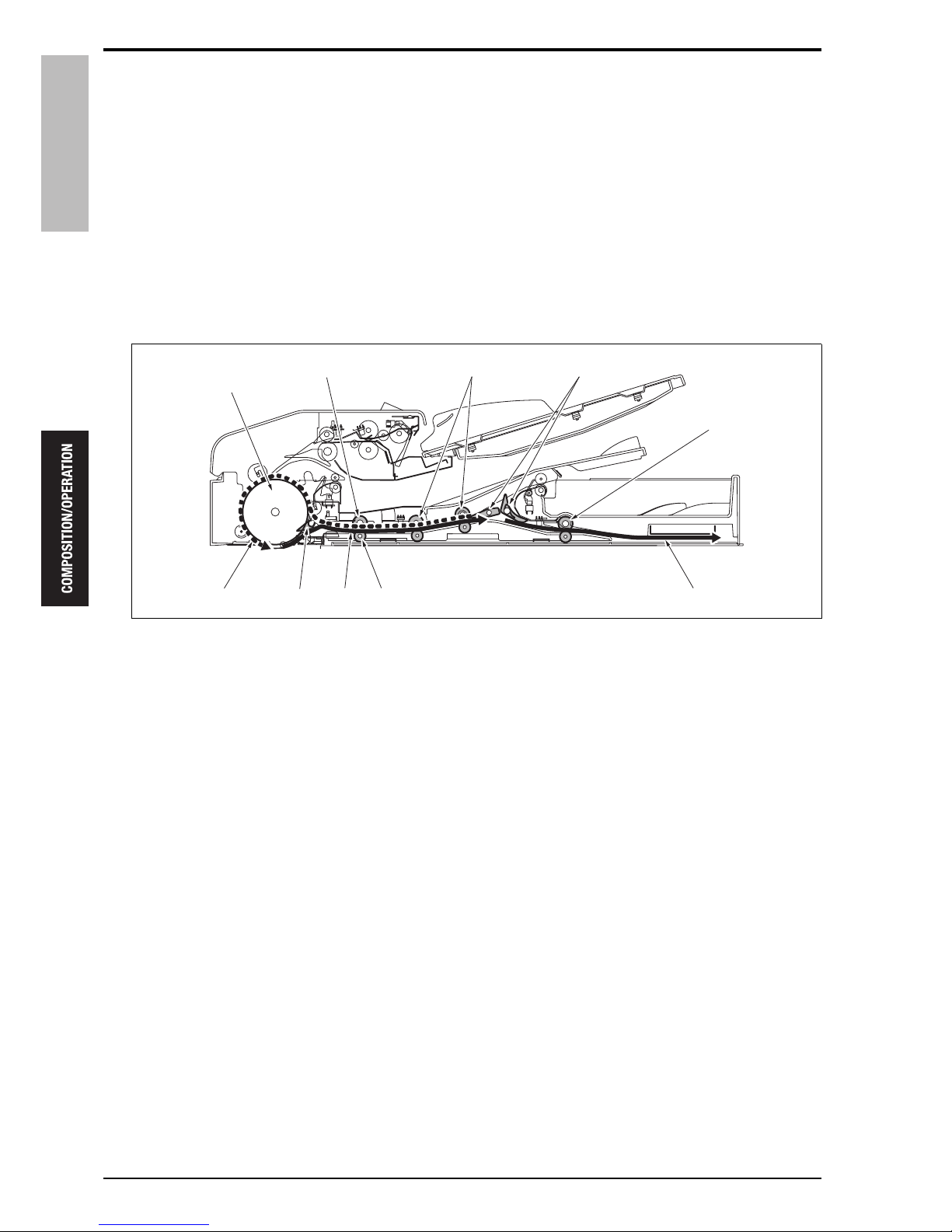
3. COMPOSITION
15sat2c001na
Original feed tray
Reverse sectionPaper exit section (for large size)
Conveyance section Paper feed section
Paper exit
section
(for small size)
Original exit tray (for large size)
Original exit tray (for small size)
4. PAPER FEED SECTION
10
Theory of Operation Ver1.0 Jun.2005
DF-606
4. PAPER FEED SECTION
4.1 Drive
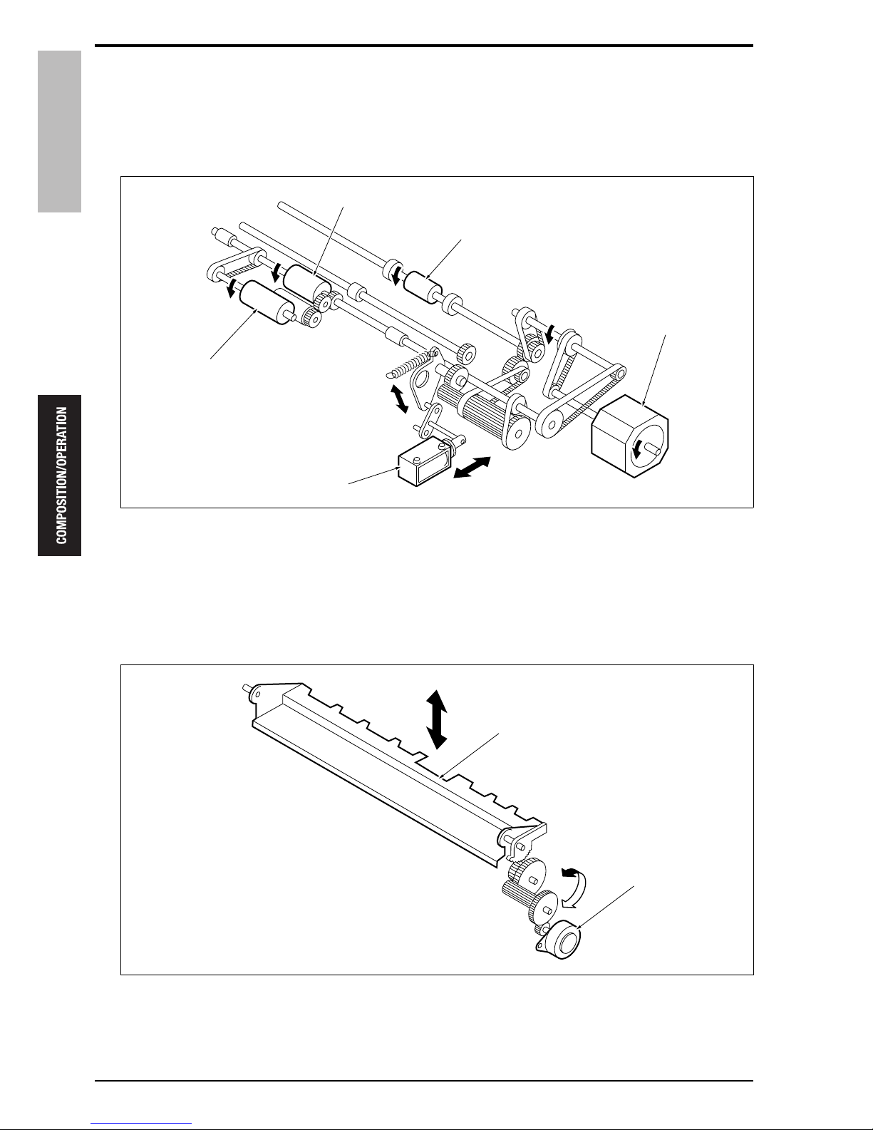
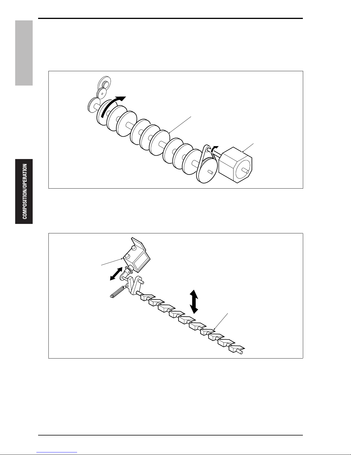
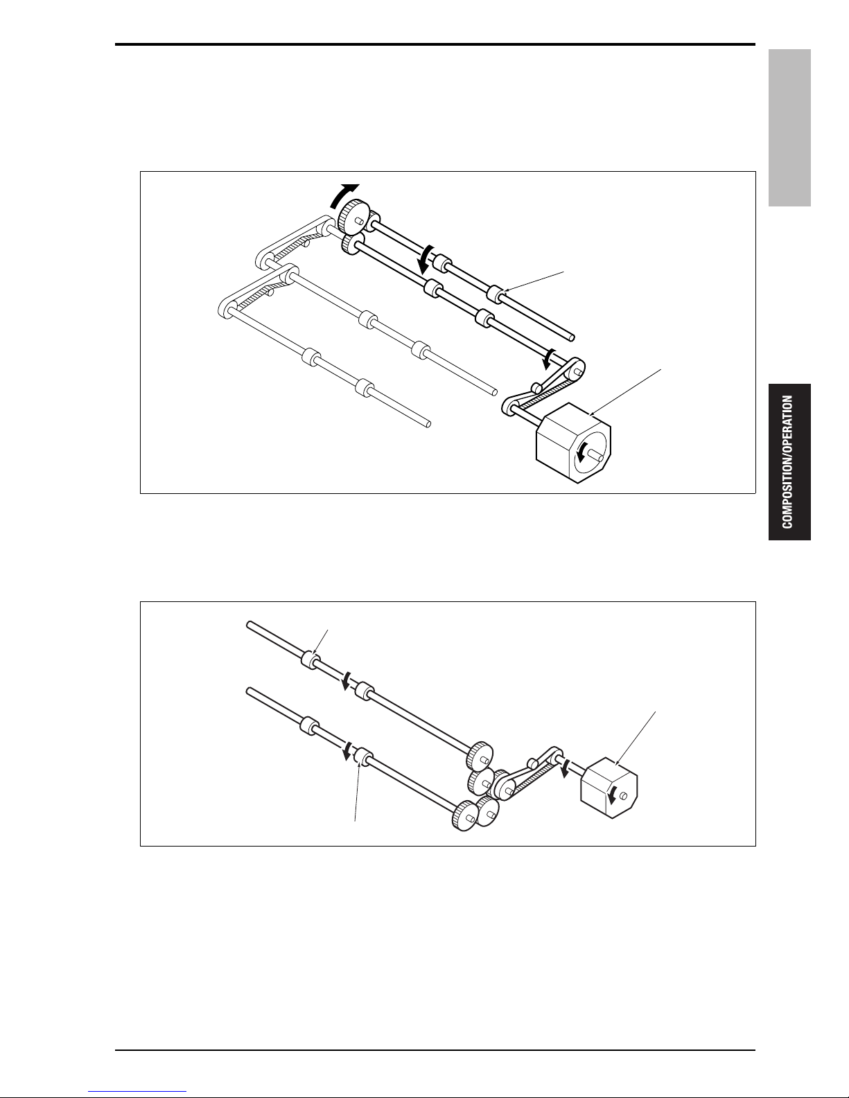
4.1.1 Paper feed drive
4.1.2 Tray up/down drive
[1] Registration roller [4] Pick-up roller
[2] Original feed motor (M302) [5] Paper feed roller
[3] SDF switching solenoid (SD304)
[1] Up/down plate [2] Tray up/down motor (M303)
15sat2c002na
[2]
[1]
[5]
[4]
[3]
15sat2c003na
[2]
[1]

DF-606
4. PAPER FEED SECTION
11
Theory of Operation Ver1.0 Jun.2005
4.2 Operation
4.2.1 Size detection control
A. Plain original mode
(1) Size detection in the main scan direction
The size detection of originals in the main scan direction is made according to the position of the guide plate
connected to the original size VR (VR301) on the original feed tray.
(2) Size detection in the sub scan direction
The size detection of originals in the sub scan direction is made according to the ON/OFF combination of the
original size sensor /Rt (PS302) and the original size sensor /Lt (PS303) provided on the original feed tray.
B. Mixed original mode
(1) Size detection in the main scan direction
This is the same as the detection method in the plain original mode.
(2) Size detection in the sub scan direction
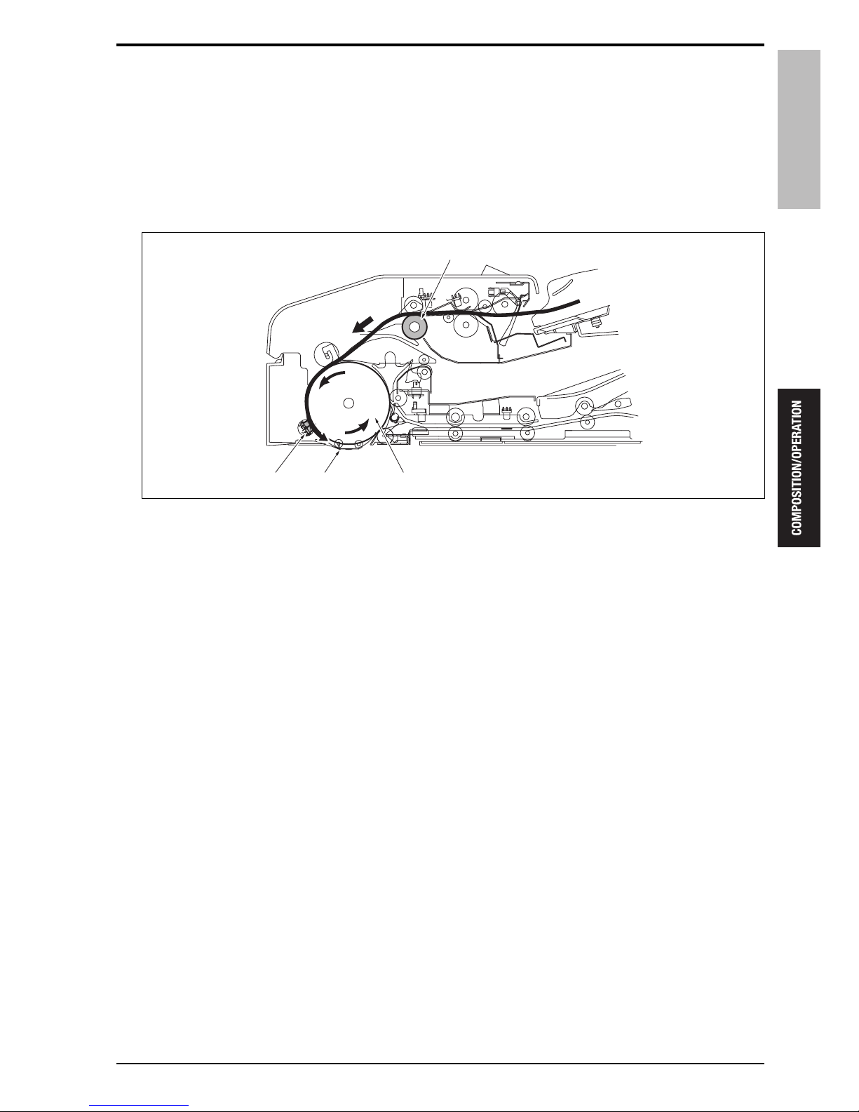
The conveyance roller [3] rotates in the forward direction to convey the original to the paper exit tray (for large
size) [2]. The conveyance roller stops rotation a specified period of time after the original registration sensor
(PS306) [1] detects the trailing edge of the original. At this time, depending on the ON time period of the PS306,
the sub scan direction and the size of the original are detected.
15sat2c004na
[3]
[2]
[1]
4. PAPER FEED SECTION
12
Theory of Operation Ver1.0 Jun.2005
DF-606
A specified period of time after the PS306 [1] turns OFF, the conveyance roller [3] rotates in the reverse direction
to get the leading edge of the original conveyed to the paper exit section back to the scan standby position [5].
The trailing edge of the original returned is conveyed to the paper exit tray (for large size) [2] according to the
form of the conveyance guide plate. The reverse rotation of the conveyance roller stops a specified period of
time after the original conveyance sensor (PS308) [4] detects the leading edge of the original.
After that, the same read (scan) operation as that in the normal mode is made.
The original size detection operation for the second and succeeding originals varies according to a copy mode
employed: the single sided original mode or the double sided original mode.
• Single sided original mode: After the scan operation of the preceding original starts.
• Double sided original mode: After the scan operation of the back side of the preceding original starts.
4.2.2 Pick-up mechanism
The original lift motor (M303) sends up the up/down plate [2] to move the original to the pick-up roller position
[1]. When the tray upper limit sensor (PS315) [4] turns ON, the M303 turns OFF to be put in the standby condition with the up/down plate left raised. The original comes into contact with the pick-up roller [3] to conduct the
pick-up (paper feed) operation.
15sat2c005na
[3]
[4]
[5]
[2]
[1]
15sat2c006na
[2]
[1]
[3]
[4]
DF-606
4. PAPER FEED SECTION
13
Theory of Operation Ver1.0 Jun.2005
4.2.3 Separation mechanism
Of the originals that have been fed by the pick-up roller, only one sheet of original is conveyed to the registration
roller side by the original feed roller and the separation roller. Even when plural sheets of originals are fed, the
separation roller makes a reverse rotation to convey a single sheet of original.
4.2.4 SDF (single document feeder) control
In the single document feeder mode, to improve the paper feedability of thick paper and other originals the
paper feed of which is not guaranteed, the SDF switching solenoid (SD304) cuts off the drive of the separation
roller to conduct the paper feed operation.
4.2.5 Original empty detection control
The detection of the presence of original in the original tray section while in the scan stop is made by the original
empty sensor (PS305). And also, the original empty detection while in the scan is made by the original set sensor (PS310) to stop the paper feed from the trays 1 to 3 and the LU after PS310 detects the trailing edge of the
last original.
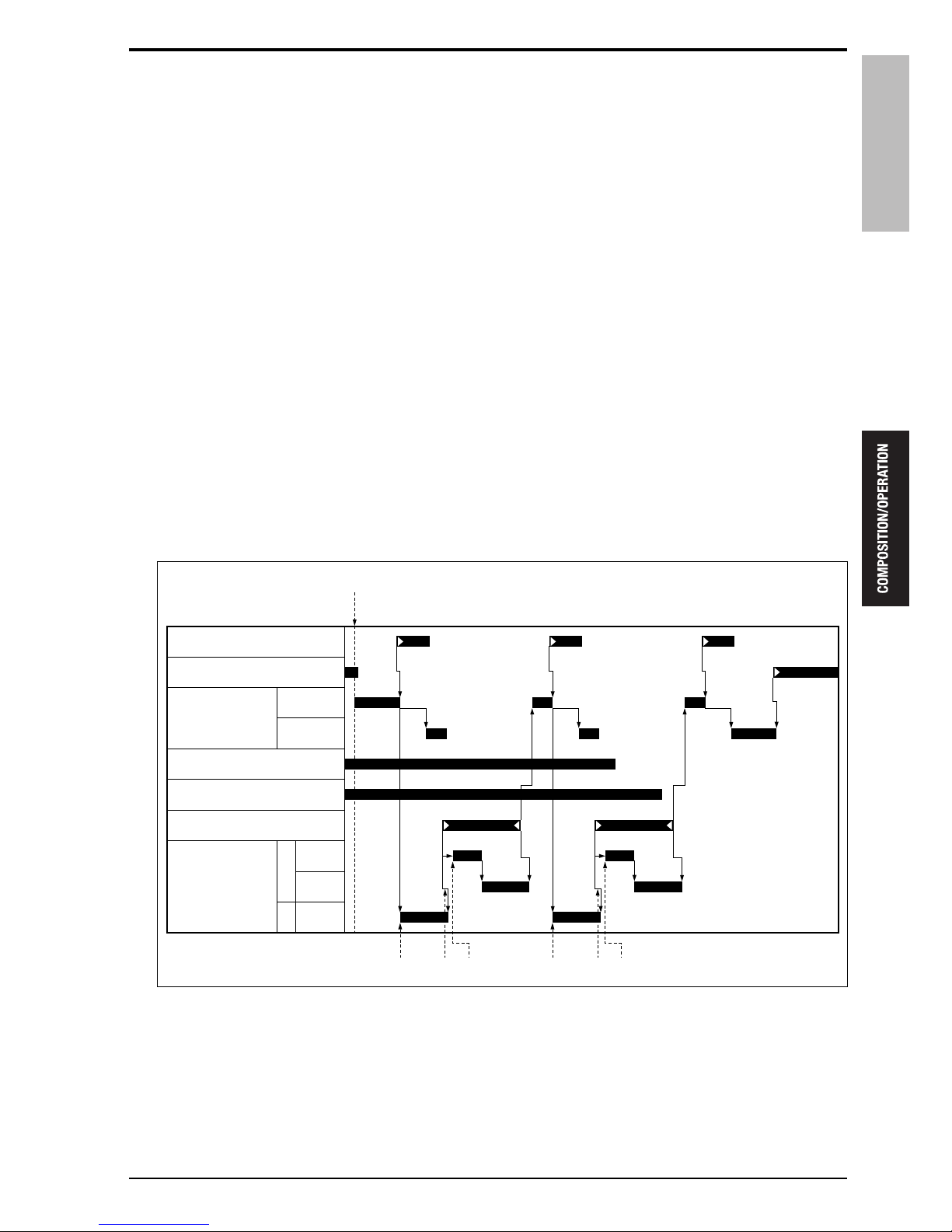
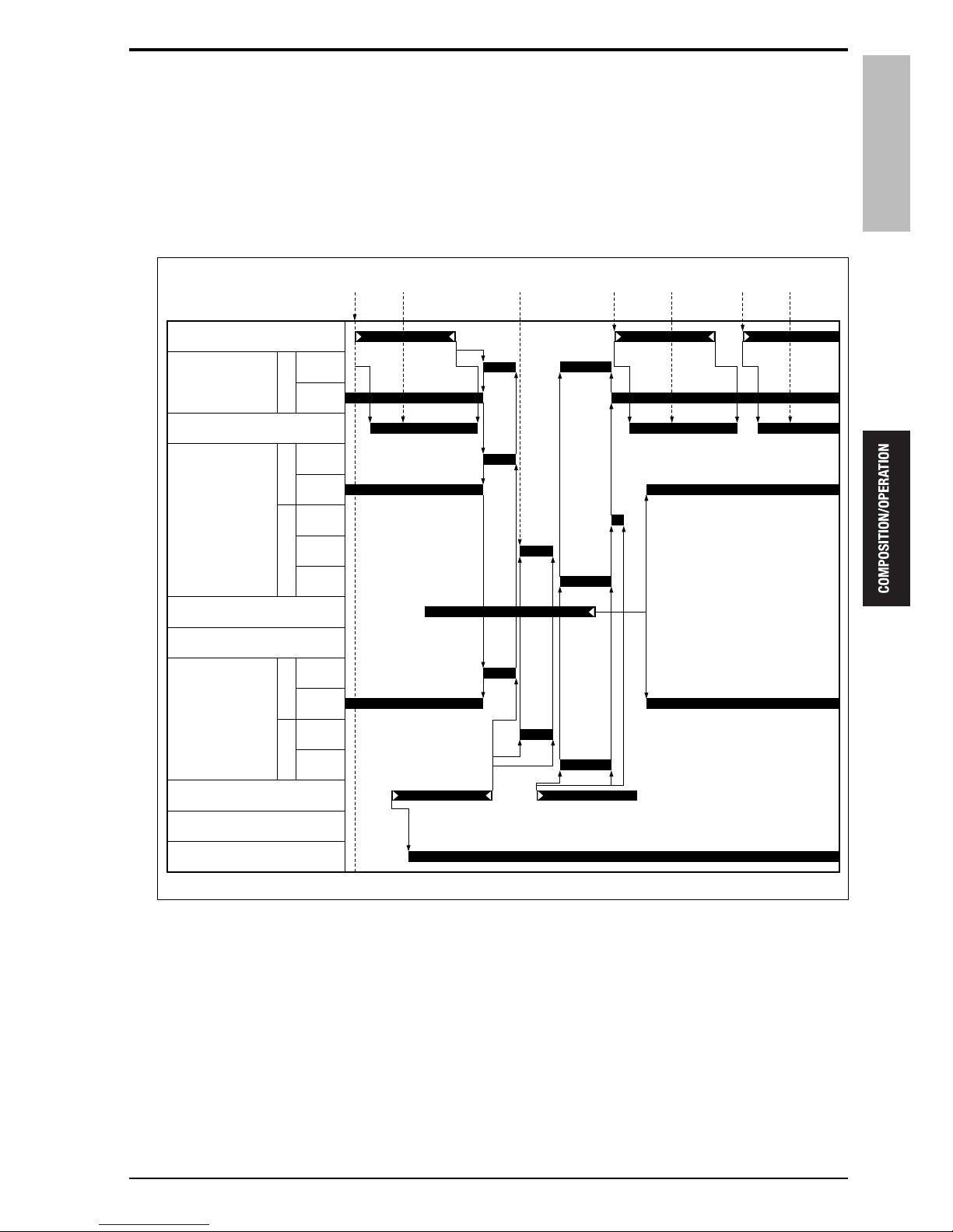
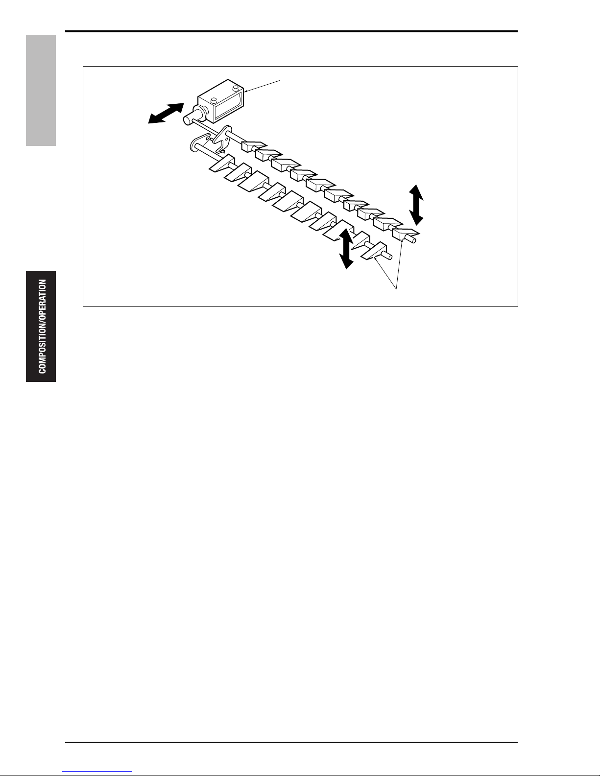
4.2.6 Registration control
When the start signal [1] on the main body is transmitted, the tray up/down motor (M303) brings up the up/
down plate until the tray upper limit sensor (PS315) turns ON [2]. A specified period of time after the PS315
turns ON, the original feed motor (M302) is driven in a reverse rotation to convey the original to the registration
roller. After a specified period of time, the up/down plate comes down by a fixed distance and a loop is formed
until the original registration sensor (PS306) turns ON to adjust an original skew.
[1] Start signal from the main body [5] Feed of the 2nd sheet of paper
[2] Feed of the 1st sheet of paper [6] Loop formation of the 2nd sheet of paper
[3] Loop formation of the 1st sheet of paper [7] Pre-feed of the 2nd sheet of paper
[4] Pre-feed of the 1st sheet of paper
15sat2c007na
[3] [4][2] [6] [7][5]
[1]
Tray upper limit sensor (PS315)
Tray up/down
motor (M303)
Original registration sensor (PS306)
Up
F
R
800 mm/s
465 mm/s
550 mm/s
Original feed
motor (M302)
Down
Tray lower limit sensor (PS316)
Original set sensor (PS310)
Original empty sensor (PS305)
5. CONVEYANCE SECTION
14
Theory of Operation Ver1.0 Jun.2005
DF-606
5. CONVEYANCE SECTION
5.1 Drive
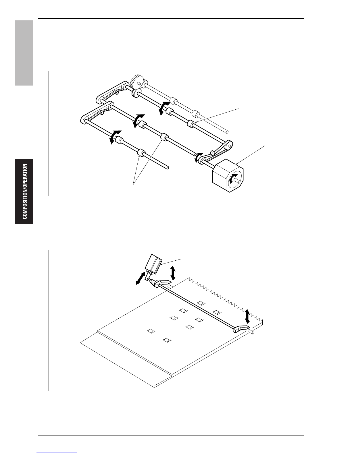
5.1.1 Conveyance drive
5.1.2 Flapper up/down drive
[1] Conveyance roller [2] Original conveyance motor (M301)
[1] Flapper [2] Gate solenoid (SD303)
15sat2c008na
[2]
[1]
15sat2c009na
[1]
[2]
DF-606
5. CONVEYANCE SECTION
15
Theory of Operation Ver1.0 Jun.2005
5.2 Operation
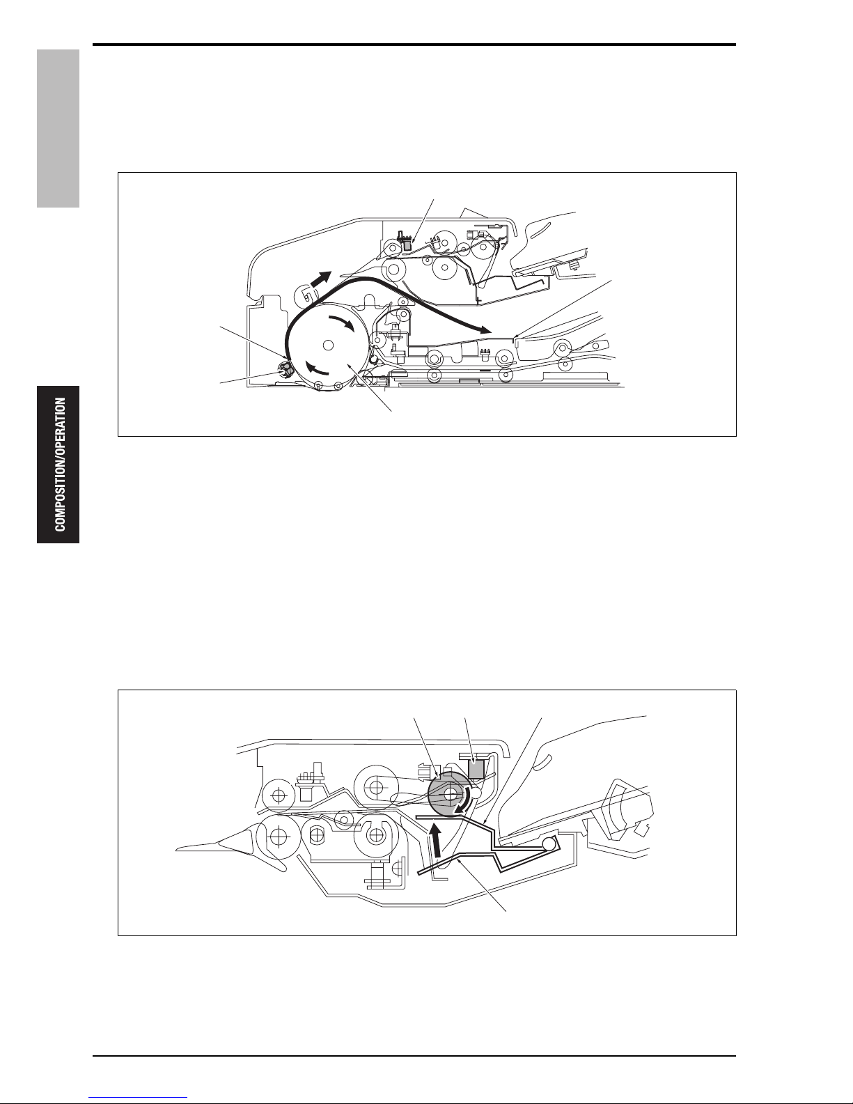
5.2.1 Conveyance control
The originals that have been fed up to the registration roller [1] by the separation mechanism are pre-fed by the
registration roller to be conveyed to the conveyance roller [2] at a high speed. A specified period of time after the
original conveyance sensor (PS308) [4] turns ON, the conveyance roller is switched into the scan speed to convey the original onto the slit glass (original scan position) [3].
The originals are read when they passes through the slit glass.
5.2.2 Mixed original mode control
The mixed original sizes copy mode is applicable to both the same size originals and the different size originals.
Since the size detection in the direction of the original sub scan is made according to the ON time of the original
registration sensor (PS306), the size detection operation is made prior to the scan operation for each original.
5.2.3 Z-fold original mode control
In the Z-fold mode, the same detection operation as that in the mixed original sizes copy mode is made on the
1st sheet of original to determine the original size. For the 2nd and succeeding originals, the normal original conveyance is made.
5.2.4 Skew adjustment control
The original skew sensor /Rr (PS311) and the original skew sensor /Fr (PS312) are provided to make adjustments when the original is conveyed with its leading edge skewed. PS311 and PS312 are provided on the front
side and the rear side of the conveyance path before scan to detect the amount of skew based on the time difference when the leading edge of the original turns ON these sensors. The amount of skew detected is adjusted
by means of image processing.
The relationship of the distance between the two sensors makes it effective only on original larger than A4R in
width and the correction of the tilt angle up to 1.5° is made.
5.2.5 Cooling fan control
To prevent the original conveyance motor (M301) from getting too hot while in operation, the motor is cooled by
the cooling fan /Lt (FM301). The FM301 turns ON when the original feed is started, and it turns OFF when the
original exit is completed.
In the same way, the original paper exit motor /1 (M304) and original paper exit motor /2 (M305) are cooled with
the cooling fan /Rt (FM302). Its operation timing is also the same as that of FM301.
15sat2c010na
[3] [2][4]
[1]
6. REVERSAL SECTION
16
Theory of Operation Ver1.0 Jun.2005
DF-606
6. REVERSAL SECTION
6.1 Drive
6.1.1 Reverse drive
6.1.2 Pressure roller release drive
[1] Reverse roller [3] Reverse conveyance roller
[2] Original paper exit motor /1 (M304)
[1] Pressure roller release solenoid (SD302)
15sat2c011na
[1]
[2]
[3]
15sat2c012na
[1]
DF-606
6. REVERSAL SECTION
17
Theory of Operation Ver1.0 Jun.2005
6.2 Operation
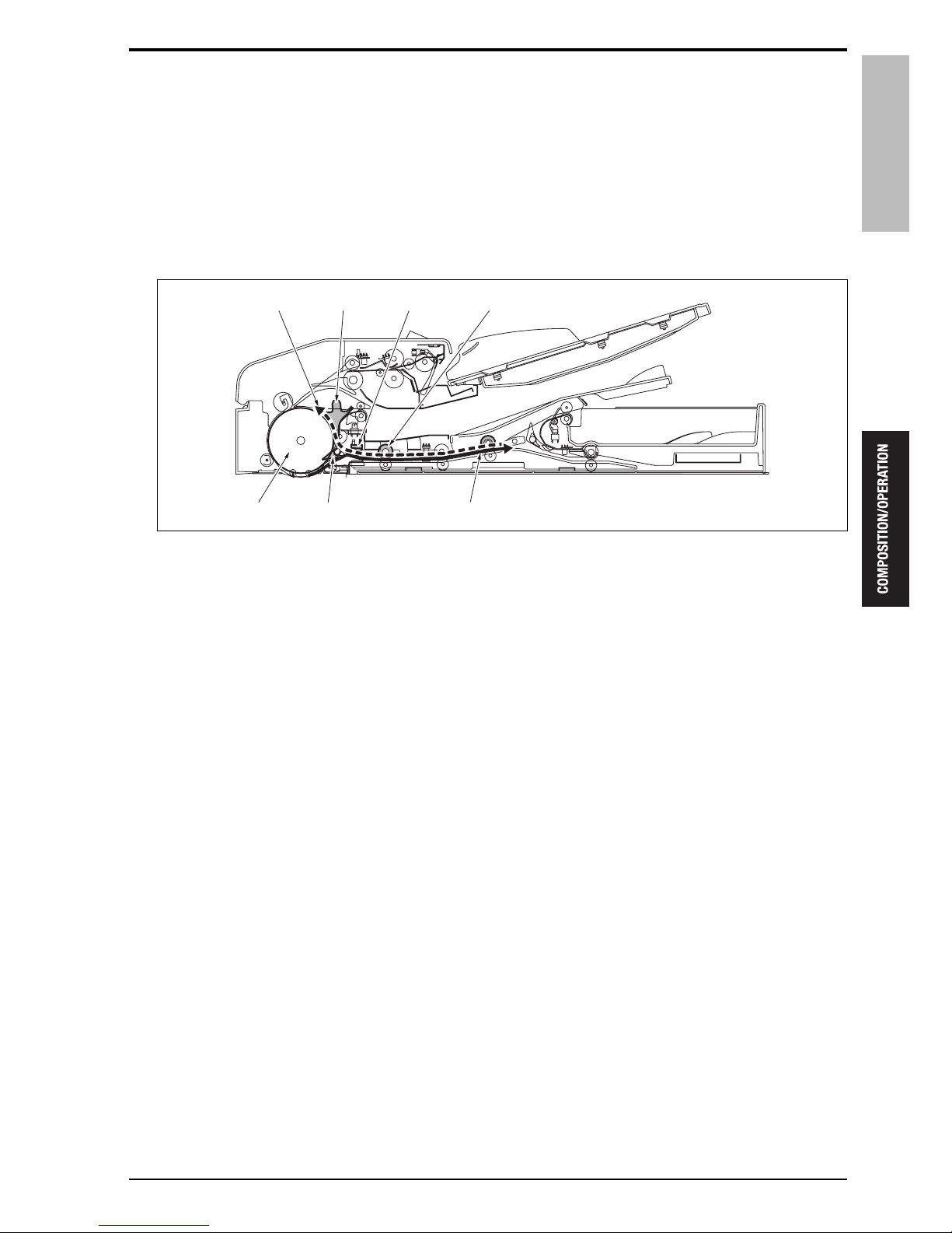
6.2.1 Reverse mechanism
A. Small size original
When the gate solenoid (SD303) starts up, the flapper [3] closes and originals the front face of which has been
scanned are conveyed [2] to the reverse section by the reverse roller [1]. A specified period of time after the original reverse sensor (PS309) [7] turns OFF by detecting the trailing edge of the original, SD303 opens the paper
exit gate [6] and the reverse paper feed [5] is made while rotating in the reverse direction at a low speed and
then at a high speed to guide the original to the conveyance roller [4].
[1] Reverse roller [5] Reverse paper feed
[2] Conveyance to the reversal section [6] Paper exit gate
[3] Flapper [7] PS309
[4] Conveyance roller
15sat2c013na
[1]
[2][4] [3]
[7][6][5]
6. REVERSAL SECTION
18
Theory of Operation Ver1.0 Jun.2005
DF-606
B. Large size original
When the gate solenoid (SD303) energizes, the flapper [5] is closed and the original the front face of which has
been scanned is conveyed [4] to the reversal section by the reverse roller [8]. The original conveyed to the reversal section, because it cannot be contained in the reversal section, is conveyed to the paper exit reversal section
[2] by the reverse conveyance roller [9] and the paper exit reverse roller [1]. At this time, the exit gate [10] is
closed by the exit gate solenoid (SD301).
The originals that have been conveyed to the reversal section and the paper exit reversal section are fed in
reverse [6] in the same manner as small size originals. At this time, since the originals do not yet pass through
the reverse roller [8] and the reverse conveyance roller [9] even if they have reached the conveyance roller [7],
after the reverse roller makes the reverse rotation, the pressure roller release solenoid (SD302) activates to
release the pressure roller [3] for the reverse roller. The originals are released from the pressure roller and guided
to the conveyance roller [7].
[1] Paper exit reverse roller [6] Reverse paper feed
[2]
Conveyance to the paper exit reversal section
[7] Conveyance roller
[3] Pressure roller [8] Reverse roller
[4] Conveyance to the reversal section [9] Reverse conveyance roller
[5] Flapper [10] Paper exit gate
15sat2c014na
[9][8] [10]
[3]
[1]
[6] [5] [4]
[7]
[2]
DF-606
6. REVERSAL SECTION
19
Theory of Operation Ver1.0 Jun.2005
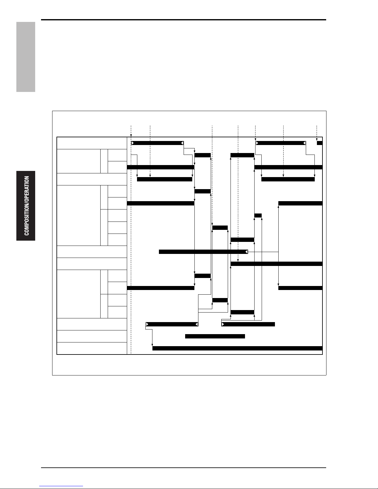
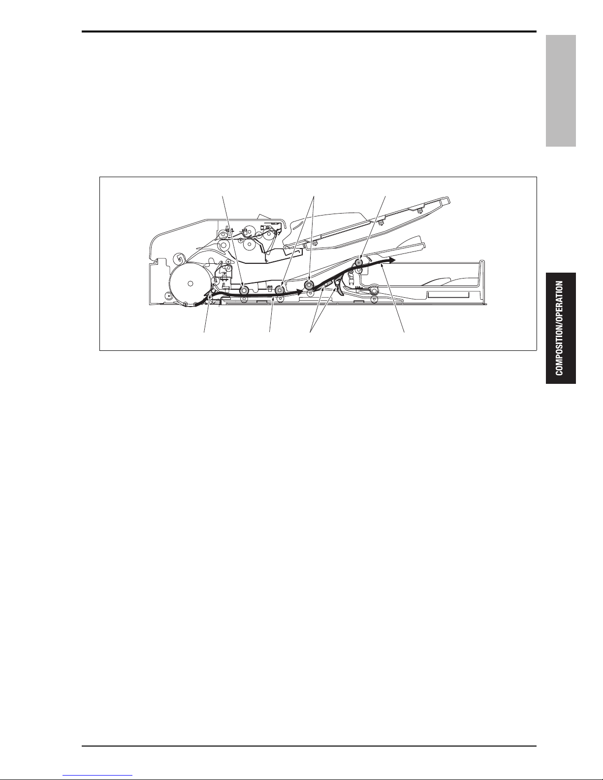
6.2.2 Registration control
A. Small size original
A specified period of time after the start of the conveyance [1] of the 1st original, the front of the 1st original is
read [2]. The 1st original conveyed to the reverse section stops temporarily after being accelerated by the original paper exit motor /2 (M305) and the original paper exit motor /1 (M304). M305 and M304 start a reverse rotation [3] to let the original hit against the conveyance roller for registration. For the original that has been
registered, a specified period of time after the original conveyance sensor (PS308) turns ON [4], the back of the
1st original is read [5].
[1] Front face of the 1st sheet of original [5]
Reading of the back face of the 1st sheet of original
[2]
Reading of the front face of the 1st sheet of original
[6] Front face of the 2nd sheet of original
[3] Reversal of the 1st sheet of original [7]
Reading of the front face of the 2nd sheet of original
[4] Back face of the 1st sheet of original
15sat2c015na
[3] [4][2]
[1]
[6] [7][5]
Original conveyance sensor (PS308)
Original
conveyance
motor (M301)
V-VALID
Original paper
exit motor /1
(M304)
Reverse jam sensor (PS304)
Pressure roller release solenoid (SD302)
Original paper
exit motor /2
(M305)
Original reverse sensor (PS309)
Original reverse/exit sensor (PS313)
Exit gate solenoid (SD301)
F
620 mm/s
465 mm/s
F
620 mm/s
465 mm/s
R
465 mm/s
550 mm/s
F
620 mm/s
465 mm/s
R
465 mm/s
620 mm/s
620 mm/s
6. REVERSAL SECTION
20
Theory of Operation Ver1.0 Jun.2005
DF-606
B. Large size original
A specified period of time after the start of the conveyance [1] of the 1st original, the front of the 1st original is
read [2]. The 1st original conveyed to the reverse section stops temporarily after being accelerated by the original paper exit motor /2 (M305) and the original paper exit motor /1 (M304). M305 and M304 start a reverse rotation [3] to let the original hit against the conveyance roller for registration. For the back of the original that has
been registered, a specified period of time after the original reverse sensor (PS309) turns ON, the pressure roller
release solenoid (SD302) is turned ON [4] to release the pressure roller, and then release the conveyance force of
the reverse section. A specified period of time after the original conveyance sensor (PS308) turns ON [5], the
back of the 1st original is read [6].
[1] Front face of the 1st sheet of original [5] Back face of the 1st sheet of original
[2] Reading of the front face of the 1st sheet of
original
[6] Reading of the back face of the 1st sheet of
original
[3] Reversal of the 1st sheet of original [7] Front face of the 2nd sheet of original
[4] Pressure roller release
15sat2c016na
[3] [4][2][1] [6] [7][5]
Original conveyance sensor (PS308)
Original
conveyance
motor (M301)
V-VALID
Original paper
exit motor /1
(M304)
Reverse jam sensor (PS304)
Pressure roller release solenoid (SD302)
Original paper
exit motor /2
(M305)
Original reverse sensor (PS309)
Original reverse/exit sensor (PS313)
Exit gate solenoid (SD301)
F
620 mm/s
465 mm/s
F
620 mm/s
465 mm/s
R
465 mm/s
550 mm/s
F
620 mm/s
465 mm/s
R
465 mm/s
620 mm/s
620 mm/s
DF-606
7. PAPER EXIT SECTION
21
Theory of Operation Ver1.0 Jun.2005
7. PAPER EXIT SECTION
7.1 Drive
7.1.1 Paper exit drive (for large size)
7.1.2 Paper exit drive (for small size)
[1] Paper exit roller /1 [2] Original paper exit motor /1 (M304)
[1] Original paper exit motor /2 (M305) [3] Paper exit roller /2
[2] Paper exit reverse roller
15sat2c017na
[1]
[2]
15sat2c018na
[1]
[2]
[3]
7. PAPER EXIT SECTION
22
Theory of Operation Ver1.0 Jun.2005
DF-606
7.1.3 Exit gate drive
[1] Paper exit gate [2] Exit gate solenoid (SD301)
15sat2c019na
[1]
[2]
DF-606
7. PAPER EXIT SECTION
23
Theory of Operation Ver1.0 Jun.2005
7.2 Operation
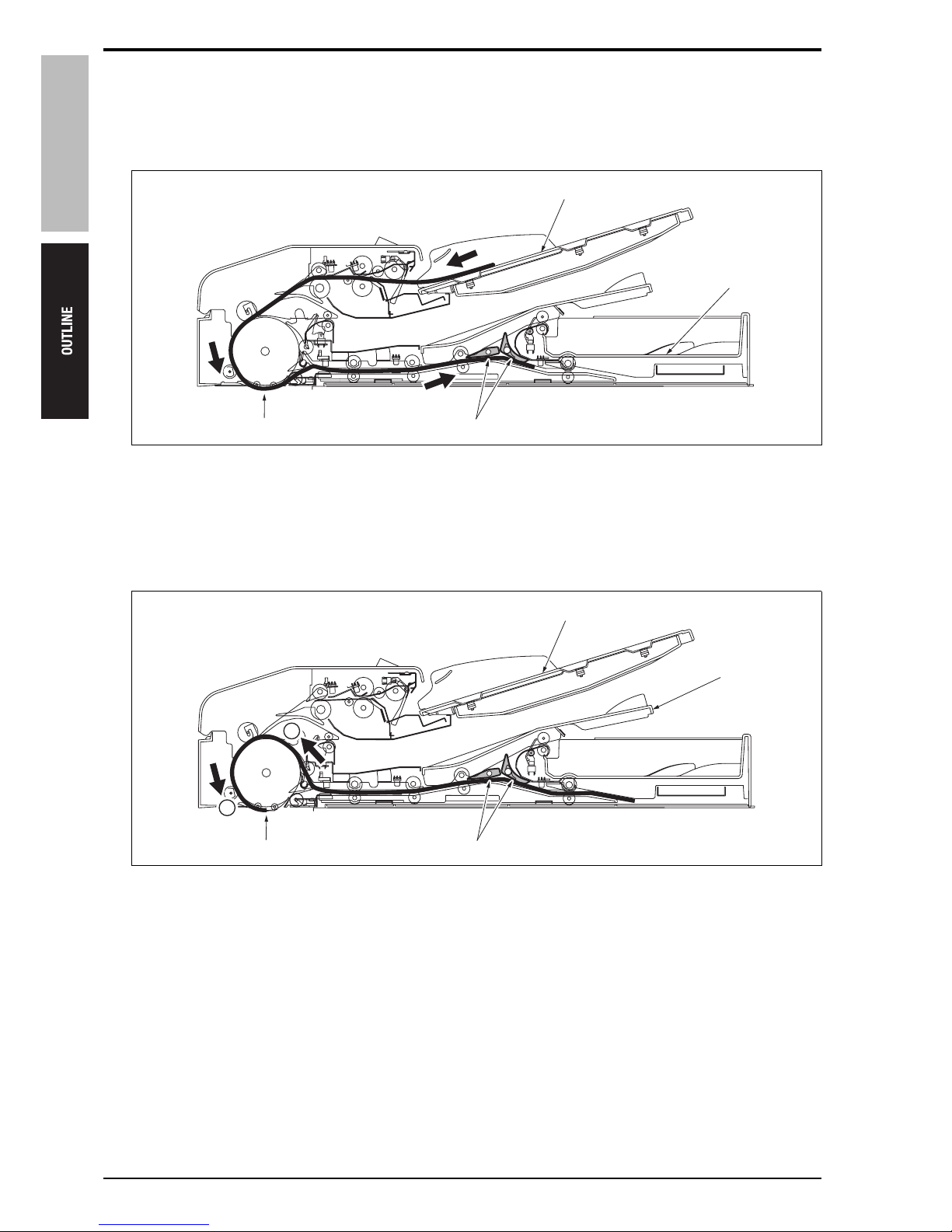
7.2.1 Paper exit operation of small size original
A. Single sided original
The originals that have been scanned are conveyed to the reversal section [3] because of the flapper [4] being
closed by the gate solenoid (SD303). The originals conveyed to the reversal section are conveyed to the exit
gate [7] by the reverse roller [5] and the reverse conveyance roller [6]. After that, they are conveyed to the paper
exit roller /2 [1] through the exit gate that has been opened by the exit gate solenoid (SD301). The paper exit
roller /2 exits the originals to the original exit tray (for small size) [2] with their copied side down.
[1] Paper exit roller /2 [4] Flapper
[2] Exits the originals to the original exit tray
(for small size)
[5]
[6]
Reverse roller
Reverse conveyance roller
[3] Conveyance to the reversal section [7] Paper exit gate
15sat2c020na
[6][5] [1]
[2][4] [3] [7]
7. PAPER EXIT SECTION
24
Theory of Operation Ver1.0 Jun.2005
DF-606
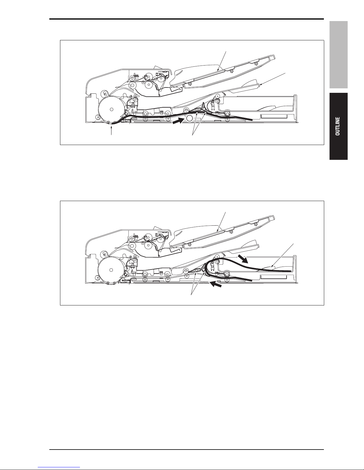
B. Double sided original
The originals the back face of which has been scanned are conveyed to the exit gate [5] in the same manner as
with the single sided originals. At this time, the gate is closed by the exit gate solenoid (SD301), and the originals
are conveyed to the paper exit reversal section [2] through the paper exit reverse roller [3]. When the original
reverse/exit sensor (PS313) [4] of the paper exit reversal section detects the originals, the paper exit reverse
roller stops. When SD301 opens the exit gate, the paper exit reverse roller starts to make a high speed reverse
rotation to send back the conveyed originals. At this time, the exit gate is open and the originals are exited [1] to
the original exit tray (for small size) with their front face down.
[1] Exits the originals to the original exit tray
(for small size)
[3]
[4]
Paper exit reverse roller
PS313
[2] Conveyance to the paper exit reversal sec-
tion
[5]
[6]
Paper exit gate
Paper exit roller /2
15sat2c021na
[6][5] [1]
[2]
[4]
[3]
DF-606
7. PAPER EXIT SECTION
25
Theory of Operation Ver1.0 Jun.2005
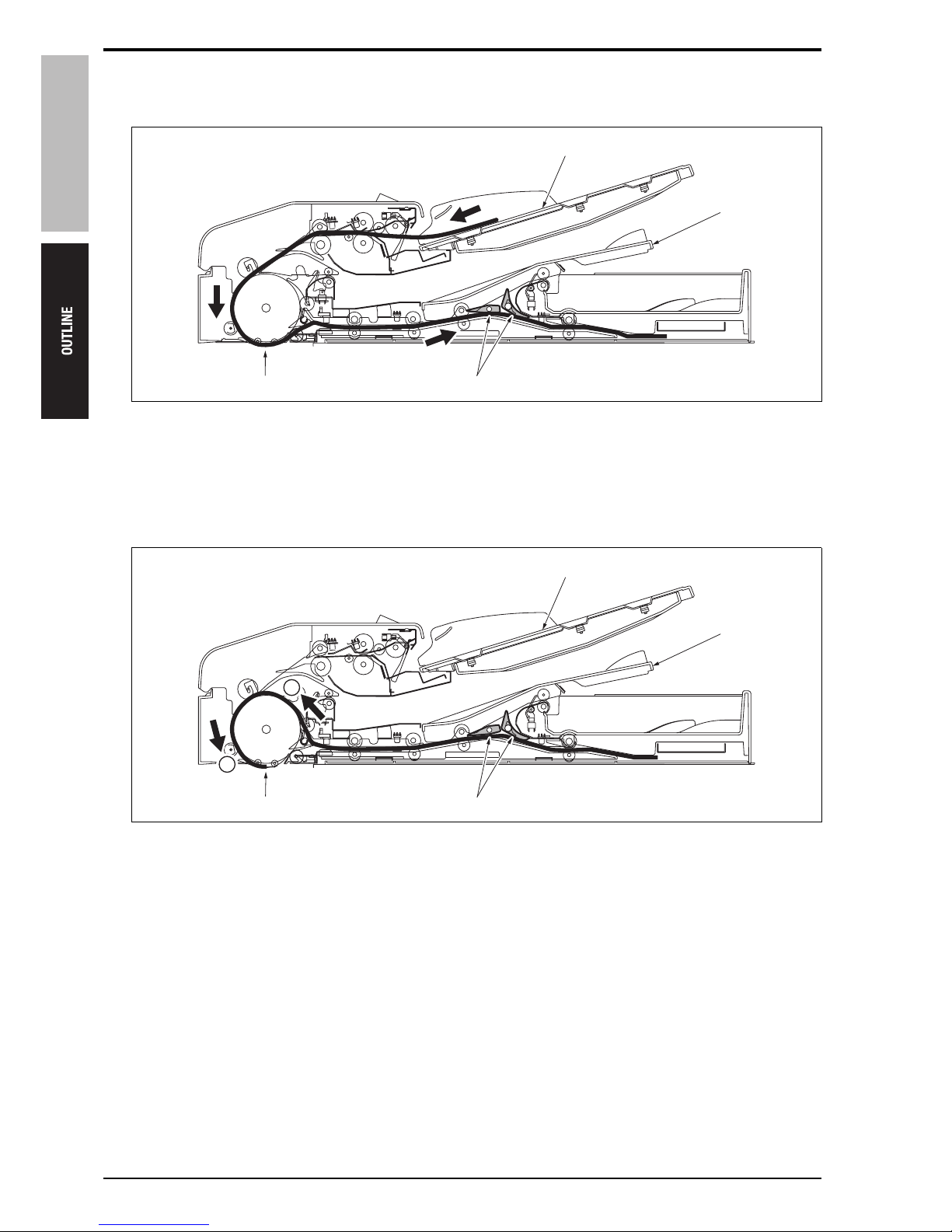
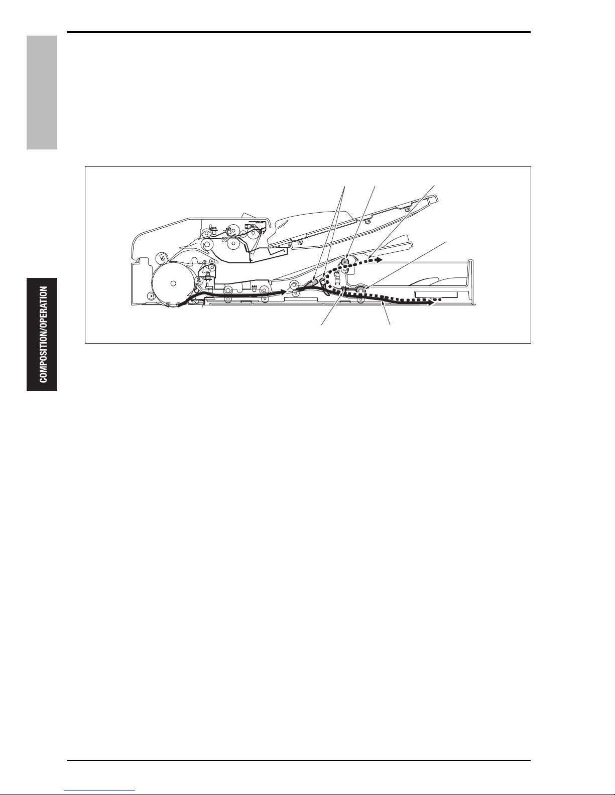
7.2.2 Paper exit operation of large size original
A. Single sided original
The originals that have been scanned are conveyed to the paper exit roller /1 [2] by the conveyance roller [4]
because of the flapper [3] and the paper exit gate [5] being opened by the gate solenoid (SD303). And then, the
paper exit roller /1 makes a low speed normal rotation to exit [1] the originals to the original exit tray (for large
size) with their copied face down.
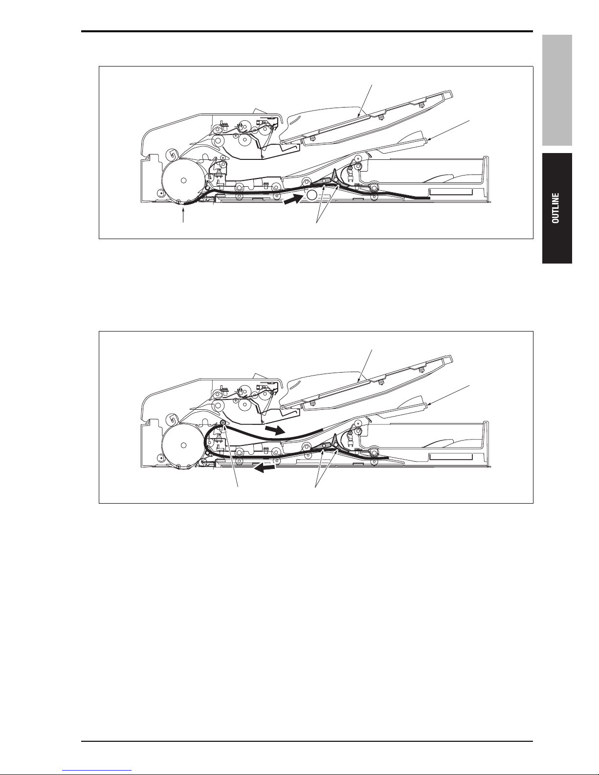
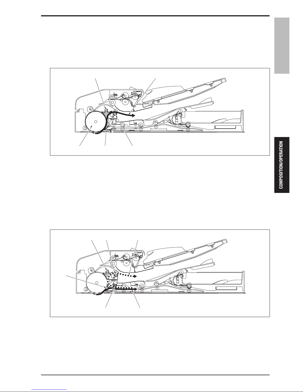
B. Double sided original
The originals the back face of which has been scanned are conveyed to the reversal section [2] because of the
flapper [4] being closed by the gate solenoid (SD303). When the original reverse sensor (PS309) [3] detects the
trailing edge of the originals conveyed, SD303 opens the flapper and the paper exit gate [5]. The originals are
exited [1] to the original exit tray (for large size) by the paper exit roller /1 [6] through the flapper that is open.
[1] Exits the originals to the original exit tray
(for large size)
[3]
[4]
Flapper
Conveyance roller
[2] Paper exit roller /1 [5] Paper exit gate
[1] Exits the originals to the original exit tray
(for large size)
[4]
[5]
Flapper
Paper exit gate
[2] Conveyance to the reversal section [6] Paper exit roller /1
[3] PS309
15sat2c022na
[1][5]
[2][4] [3]
15sat2c023na
[1]
[5]
[6]
[2]
[4]
[3]

7. PAPER EXIT SECTION
26
Theory of Operation Ver1.0 Jun.2005
DF-606
Blank page
 Loading...