

Page 1

INSTALLATION MANUAL
DF-601
Reverse Automatic Document Feeder
for Product Code 4036
NOTES
• Before installing, be sure to unplug the power cord of the machine.
• Keep all packing materials out of the reach of children.
4582-7761-02 Printed in Japan
Page 2
DF-601
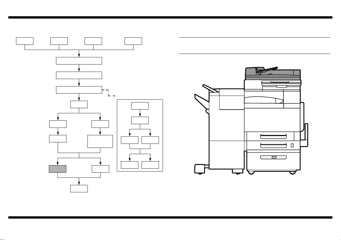
■ Outline of Installation Procedures for 4036 System
PC-101
PC-201 DK-501
Dehumidifier Heater 1C
Copier/Printer Machine
Electron System Options
FS-501
JS-601
DF-601
PC-401
✱ Electron System Options
AD-501
FS-601
PK-501/PK-4/
PK-131
OC-501
WT-501
EM-301
HD-501
EK-501 VI-501
D-103DT-105
When installing the machine and associated options as a system, follow the order shown
on the left.
NOTE
For the detailed installation procedures for each option, follow the instructions given
in the corresponding Installation Manual and perform the procedures correctly.
4582U017AA
– 1 –
Page 3

■ Unpacking the Reverse Automatic Document Feeder
Check that the following accessories are available in the box.
1 Shoulder screw ......................................................................................2
2 Mounting screw ......................................................................................2
3 Chart ......................................................................................................1
4 Installation Manual (this manual) ...........................................................1
3
1 2
DF-601
4. Using the two mounting screws furnished with the Document Feeder, tighten the
hinges to secure the Document Feeder in position.
NOTE
Check that the shoulder screws are fully tightened.
4
4582U010AA 4582U011AA
■ Installing the Document Feeder
C4652U011AA
C4652U012AA
1. Remove the two hinge covers at two places
(one screw each).
2. Screw the shoulder screws furnished with
the Document Feeder into the holes in the
rear (one screw each).
3. Place the Document Feeder in position.
NOTE
When installing the Document Feeder, hold
onto the upper and lower ends of the
Document Feeder in the vertical position as
shown on the left.
4582U001AD
5. Remove the plastic bag of the hookup cable.
6. Remove the cover and connect the hookup
cable to the machine.
4582U018AA
– 2 –
Page 4

DF-601
■ Adjusting the Document Feeding Tray Width
1. Plug the power cord into the power outlet
and turn on the machine.
2. Widen the width across the edge guides by
sliding them to their maximum width.
4582U013AA
3. Display the Tech. Rep. Mode screen.
(For details of how to display the Tech. Rep.
Mode screen, see the Service Manual.)
4. Touch “ADF Check.”
4036P031CA
5. Touch “Tray Width Adjust.”
4582P016CA
6. Touch “Max. Width” and then press the Start
key.
Check that “Result” is “OK.”
4582U014AA
4582P015CA
7. Narrow the width across the edge guides by
sliding them to their minimum width.
8. Touch “Min. Width” and then press the Start
key.
Check that “Result” is “OK.”
9. Touch “END.”
10. Touch “Fin. Time” on the Tech. Rep. Mode
screen.
4582P014CA
– 3 –
Page 5

DF-601
■ Checking and Adjusting the Document Feeding Tray Reference Position
1. Place the chart furnished with the Document
Feeder in the document feeding tray (with
the side having an arrow facing up).
2. Set up the following functions:
4582U003AA
<Metric Areas for standard line>
A
B
<Inch Areas for standard line>
A
B
4582U005AC
• Auto Paper
• 1-sided original 1-side copy
3. Press the Start key.
4. Fold the copy in half.
5. With reference to the crease, check to see if
the arrow is on the side of A or B.
Specifications: ±2 mm from the center
* If the deviation falls outside the specified
range, use the following procedure to make
an adjustment.
6. Loosen the screw (two on the front side and
three on the backside) on the document
feeding tray.
If the crease deviates on the side of A, move
the tray to the front.
If the crease deviates on the side of B, move
the tray to the rear.
7. Tighten the five screws.
▲
■ Checking and Adjusting Document Skew
1. Place the chart furnished with the Document
Feeder in the document feeding tray (with
the side having an arrow facing up).
2. Set up the following functions:
• Auto Paper
• 1-sided original 1-side copy
4582U003AA
3. Press the Start key.
4. Check in which direction, A or B, the image
tilts on the copy fed out of the machine.
Specifications: Tilt 3 mm max.
4582U006AC
4582U007AC
* If the image tilts more than the specifications,
perform the following steps to make the
adjustment.
5. Loosen the two front screws on the right
hinge.
If the image tilts in direction of A, move the
Document Feeder toward the front.
If the image tilts in direction of B, move the
Document Feeder toward the rear.
6. Tighten the two screws.
7. Make the copy and check again.
▲
8. Make the copy and check again.
– 4 –
Page 6

DF-601
■ Adjusting the Document Stop Position
1. Display the Tech. Rep. Mode screen.
(For details of how to display the Tech. Rep.
Mode screen, see the Service Manual.)
2. Touch “ADF Check.”
4036P031CA
3. Touch “Auto Adjust Stop Position.”
4582P016CA
4. Touch “FD 1-Sided.”
4582P009CA
5. Place the chart furnished with the Document
Feeder in the document feeding tray (with
the side having an arrow facing up).
6. Press the Start key.
4582P010CA
4582P011CA
4582P012CA
7. Make sure that “Result” is “OK.” Then, touch
“SET.”
8. Touch “FD 2-Sided.”
9. Place the chart furnished with the Document
Feeder in the document feeding tray.
NOTE
Make sure that the blank surface of the
chart faces up.
10. Press the Start key.
11. Check that “Result” is “OK” and then touch
“SET.”
12. Touch “CD.”
13. Place the chart furnished with the Document
Feeder in the document feeding tray (with
the side having an arrow facing up).
14. Press the Start key.
15. Check that “Result” is “OK” and then touch
“SET.”
4582U003AA
– 5 –
Page 7

16. Touch “END.”
17. Touch “Fin. Time” on the Tech. Rep. Mode
screen.
■ Fixing the Stoppers
Loosen the stopper screws (two each on the right and left). Then, with the stoppers
raised, tighten the screws.
4582U008AB 4582U009AB
DF-601
– 6 –
 Loading...