

Konica Minolta DF-502 Service Manual

SERVICE MANUAL
DF-502
THEORY OF OPERATION
2005.04
Ver. 1.0

After publication of this service manual, the parts and mechanism may be subject to change for
improvement of their performance.
Therefore, the descriptions given in this service manual may not coincide with the actual machine.
When any change has been made to the descriptions in the service manual, a revised version will be
issued with a revision mark added as required.
Revision mark:
• To indicate clearly a section revised, show to the left of the revised section.
A number within represents the number of times the revision has been made.
1
1
• To indicate clearly a section revised, show in the lower outside section of the correspond-
1
ing page.
A number within represents the number of times the revision has been made.
1
NOTE
Revision marks shown in a page are restricted only to the latest ones with the old ones deleted.
• When a page revised in Ver. 2.0 has been changed in Ver. 3.0:
The revision marks for Ver. 3.0 only are shown with those for Ver. 2.0 deleted.
• When a page revised in Ver. 2.0 has not been changed in Ver. 3.0:
The revision marks for Ver. 2.0 are left as they are.
2005/04 1.0 — Issue of the first edition
Date Service manual Ver. Revision mark Descriptions of revision


Theory of Operation Ver. 1.0 Apr. 2005
CONTENTS
Outline
1. Product specification ............................................................................................... 1
Composition/Operation
2. Automatic Document Feeder (DF-502) ................................................................... 3
2.1 Construction ......................................................................................................... 3
2.2 Operation .............................................................................................................. 4
2.2.1 Document Take-Up and Feed ....................................................................... 4
2.2.2 Document Transport...................................................................................... 5
2.3 Electrical Parts Layout .......................................................................................... 6
2.4 Document Separating Mechanism........................................................................ 7
2.5 Document Exit Mechanism ................................................................................... 8
2.6 Document Size Detection Mechanism.................................................................. 9
DF-502OutlineComposition/Operation
2.7 Raised/Lowered Position Detection Mechanism................................................... 9
i

DF-502
OutlineComposition/Operation
Theory of Operation Ver. 1.0 Apr. 2005
Blank page
ii
Theory of Operation Ver. 1.0 Apr. 2005 1. Product specification
Outline
1. Product specification
Name Automatic Document Feeder
Installation Inserted in top portion of the copier
Modes Standard = 1-sided original
Mixed Original = 1-sided original
Document Loading Left-hand side, face up
Types and Sizes of Document
Standard Mixed Original
Ty pe
Sizes
Document Alignment Center
Capacity
Power Requirements DC24 V, DC5 V (supplied from the copier)
Power Consumption 36 W or less
Dimensions Width = 598 mm, Depth = 483 mm, Height = 102 mm
Mass 6.3 kg
Operating Environment Conforms to that of the copier
Plain paper (50 to 110 g/m2) Plain paper (60 to 90 g/m2)
A3, A4 R, A4, A5 R, B4, B5 R, B5,
11 x 17, 11 x 14, Legal, Letter R, Letter,
Invoice R, and Invoice
50 sheets max. (80 g/m
A3 and A4, B4 and B5, 11 x 17 and
Letter, Legal and Letter R, Legal and
Invoice, Letter R and Invoice
2
)
DF-502Outline
Types of Originals Not Guaranteed for Reliable Feeding
Type of Original Possible Problems
Sheets stapled or clipped together
Sheets glued together Take-up failure, damaged sheet
Sheets folded, torn, or wrinkled Take-up failure, damaged sheet
Sheets severely curled
Take-up failure, damaged sheet, defective drive
mechanism due to jammed staples or clips
Sheet misfed due to its being dog-eared or fed in
askew
1

1. Product specification Theory of Operation Ver. 1.0 Apr. 2005
DF-502
Outline
Blank page
2

Theory of Operation Ver. 1.0 Apr. 2005 2. Automatic Document Feeder (DF-502)
Composition/Operation
2. Automatic Document Feeder (DF-502)
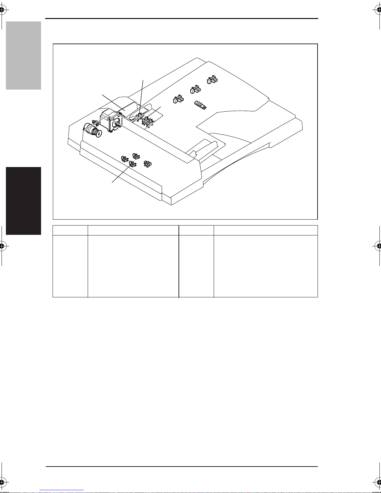
2.1 Construction
1
6
5
DF-502Composition/Operation
2
3
4
[1] Main Motor [4] Registration Rollers
[2] Pick-Up Roller [5] Take-Up Roller
[3] Exit Rollers [6] Take-Up Clutch
4688M502AA
3
2. Automatic Document Feeder (DF-502) Theory of Operation Ver. 1.0 Apr. 2005
2.2 Operation
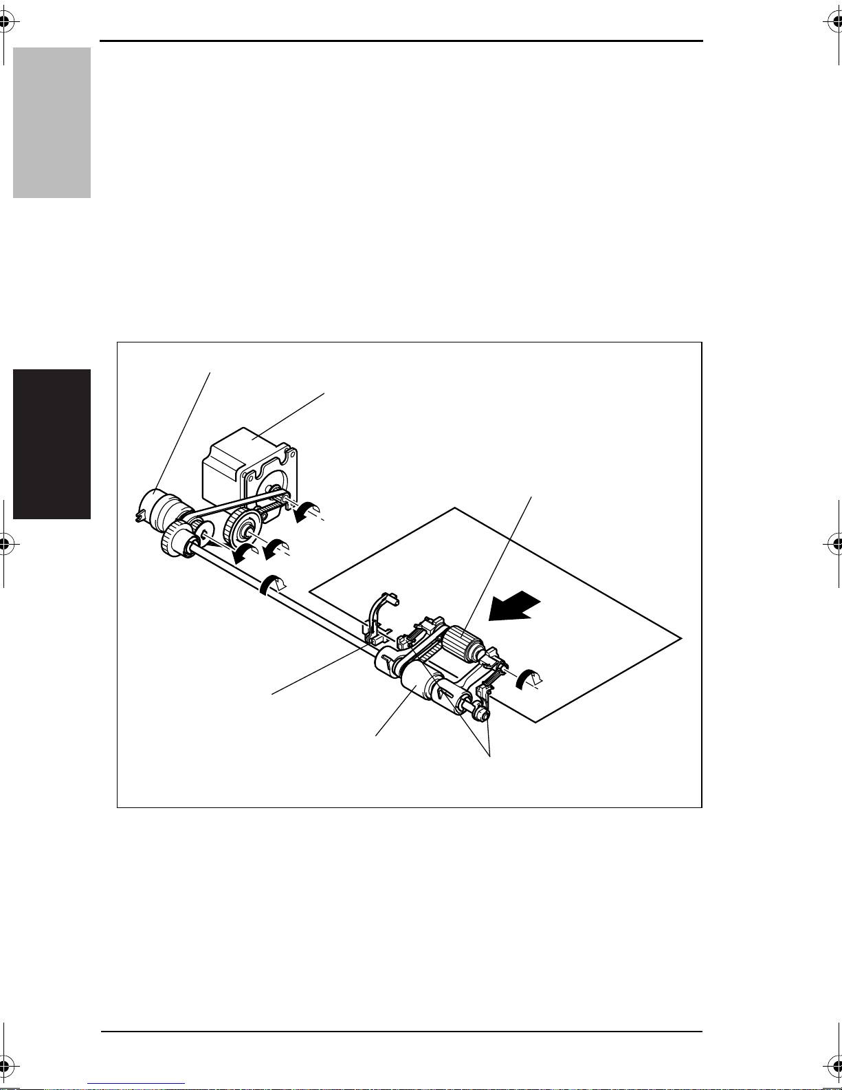
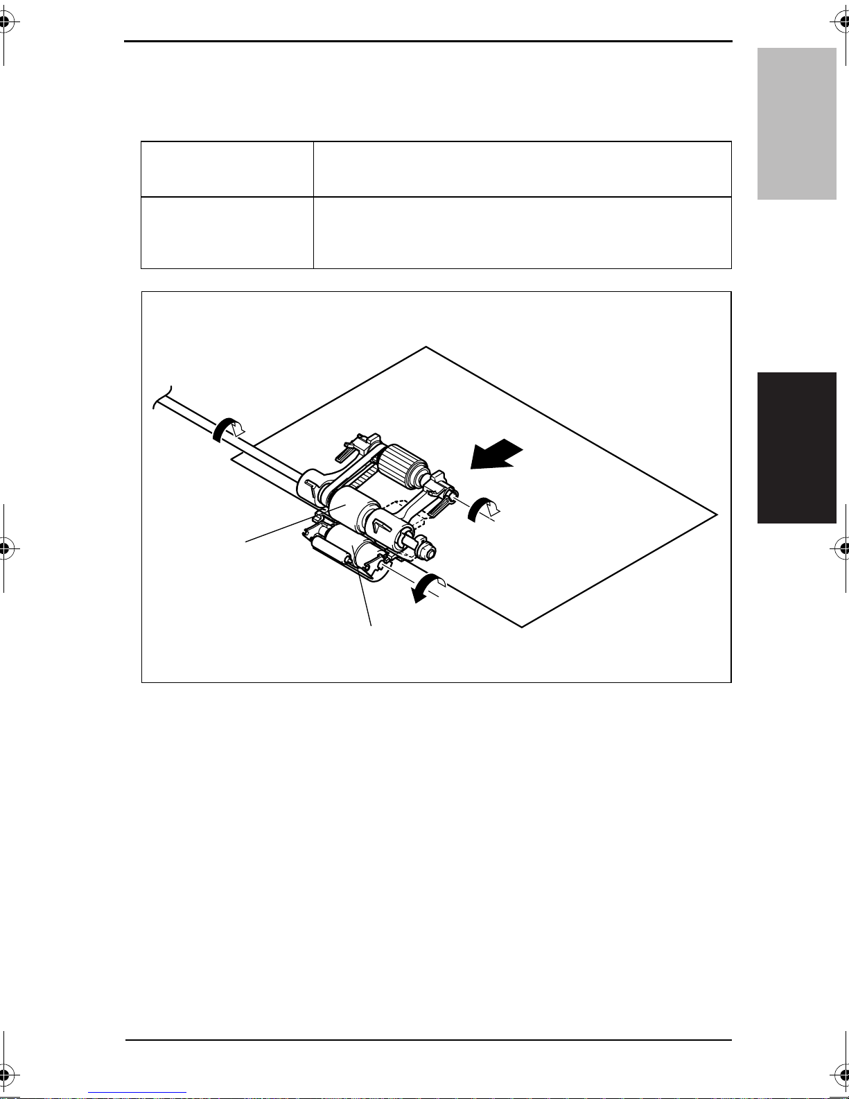
2.2.1 Document Take-Up and Feed
• The document is taken up as the Pick-Up Roller and Take-Up Roller turn.
DF-502
• The Pick-Up Roller transports the document up to the Take-Up Roller.
• After a scan is completed, the Main Motor is turned backward to raise the Pick-Up Roller.
• The Pick-Up Roller and the Take-Up Roller are turned through the Paper Take-Up Clutch
and by a gear train and a belt driven by the Main Motor.
• The Paper Empty Sensor is used to detect a document loaded on the Document Loading
Tr ay.
• The Document Stoppers determine the leading edge position of the document loaded on
the Document Loading Tray. They are in the lowered, swung-down position in the
standby state and swing upward when the document is to be taken up.
• The swing-up and swing-down motion of the Document Stoppers is operatively connected to the raising and lowering of the Pick-Up Roller.
Paper Take-Up Clutch (CL1)
Main Motor (M1)
Composition/Operation
Pick-Up Roller
Paper Empty Sensor (PC2)
4688M005AA
Take-Up Roller
Document Stoppers
4
Theory of Operation Ver. 1.0 Apr. 2005 2. Automatic Document Feeder (DF-502)
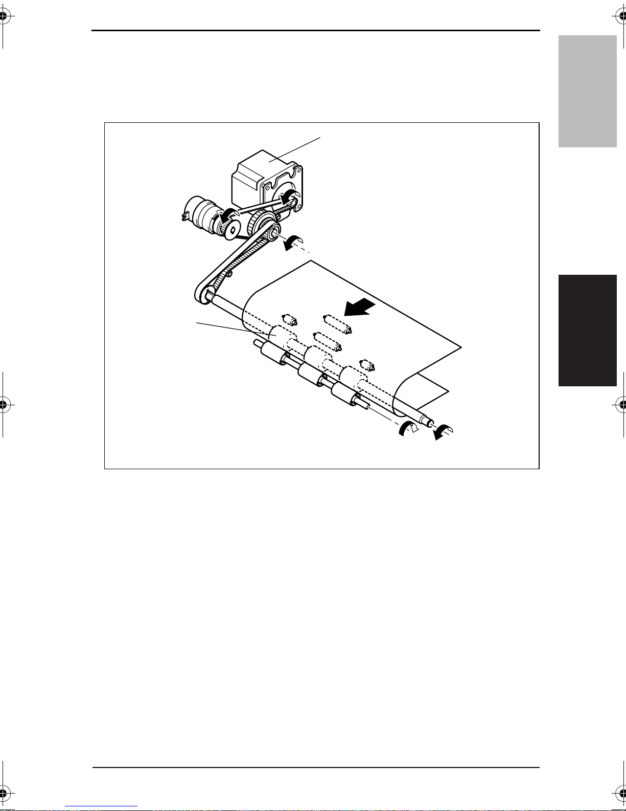
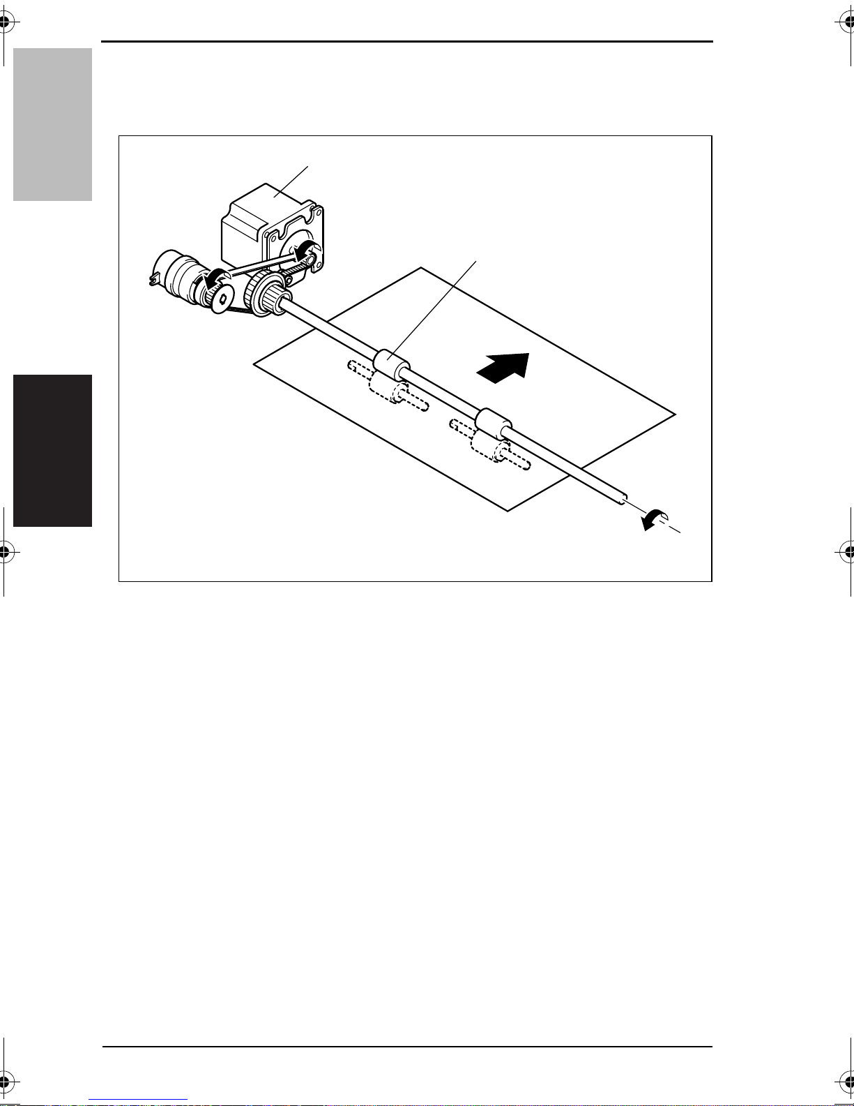
2.2.2 Document Transport
• The document taken up is transported to the document scanning position of the copier
by the Registration Rollers.
• The Registration Rollers are turned by a gear train and belts which are driven by the
Main Motor.
Main Motor (M1)
DF-502Composition/Operation
Registration Rollers
4688M007AA
5
2. Automatic Document Feeder (DF-502) Theory of Operation Ver. 1.0 Apr. 2005
2.3 Electrical Parts Layout
DF-502
CL1
Composition/Operation
Symbol Name Symbol Name
PWB
M1
CL1
PC1
PC2
PC3
PC4
PC12
PWB
PC1
PC2
PC4
PC3
Interface Board
Main Motor
Paper Take-Up Clutch
Take-Up Cover Open/Close
Detecting Sensor
Paper Empty Sensor
Registration Sensor
Separator Sensor
PC11
PC10
PC5
PC6
PC8
PC5
PC6
PC7
PC8
PC9
PC10
PC11
PC12
PC9
PC7
4688M505CA
Paper Exit Sensor
Length Size Detection Sensor 1
Length Size Detection Sensor 2
Length Size Detection Sensor 3
Length Size Detection Sensor 4
Width Size Detection Sensor 1
Width Size Detection Sensor 2
Width Size Detection Sensor 3
6
Theory of Operation Ver. 1.0 Apr. 2005 2. Automatic Document Feeder (DF-502)
2.4 Document Separating Mechanism
• The coefficient of friction between the Take-Up Roller and Separation Roller is effectively
used to prevent double feed of paper.
When one sheet of paper is
taken up
When two or more sheets of
paper are taken up
Since the friction coefficient on the top side of the paper is equal to that
on the underside of the paper, the Separation Roller is turned by the
Take-up Roller. This feeds the paper forward.
The friction coefficient between the sheets of paper is smaller than that
between the paper and Separation Roller. This stops the Separation
Roller, allowing only the first sheet of paper to be transported by the
Take-up Roller.
DF-502Composition/Operation
Take-Up Roller
Separation Roller
4688M006AA
7
2. Automatic Document Feeder (DF-502) Theory of Operation Ver. 1.0 Apr. 2005
2.5 Document Exit Mechanism
• The document is fed out of the ADF by the Exit Roller.
• The Exit Roller is driven by gears and a belt which are driven by the Main Motor.
DF-502
Composition/Operation
Main Motor (M1)
Exit Rollers
4688M008AA
8
Theory of Operation Ver. 1.0 Apr. 2005 2. Automatic Document Feeder (DF-502)
2.6 Document Size Detection Mechanism
• The document size is determined by means of two different systems of document width
detection and document length detection.
✽ Document Width Detection
• The width of an original is detected by the combination of Paper Width Sensors as
detected while the original is being taken up.
• Each sensor is located as follows with reference to the Document Edge Guide in the rear.
✽ Document Length Detection
• The length of the original is detected by the Paper Length Sensor when the document is
loaded in the unit.
• The Paper Length Sensor is located at the Document Loading Tray.
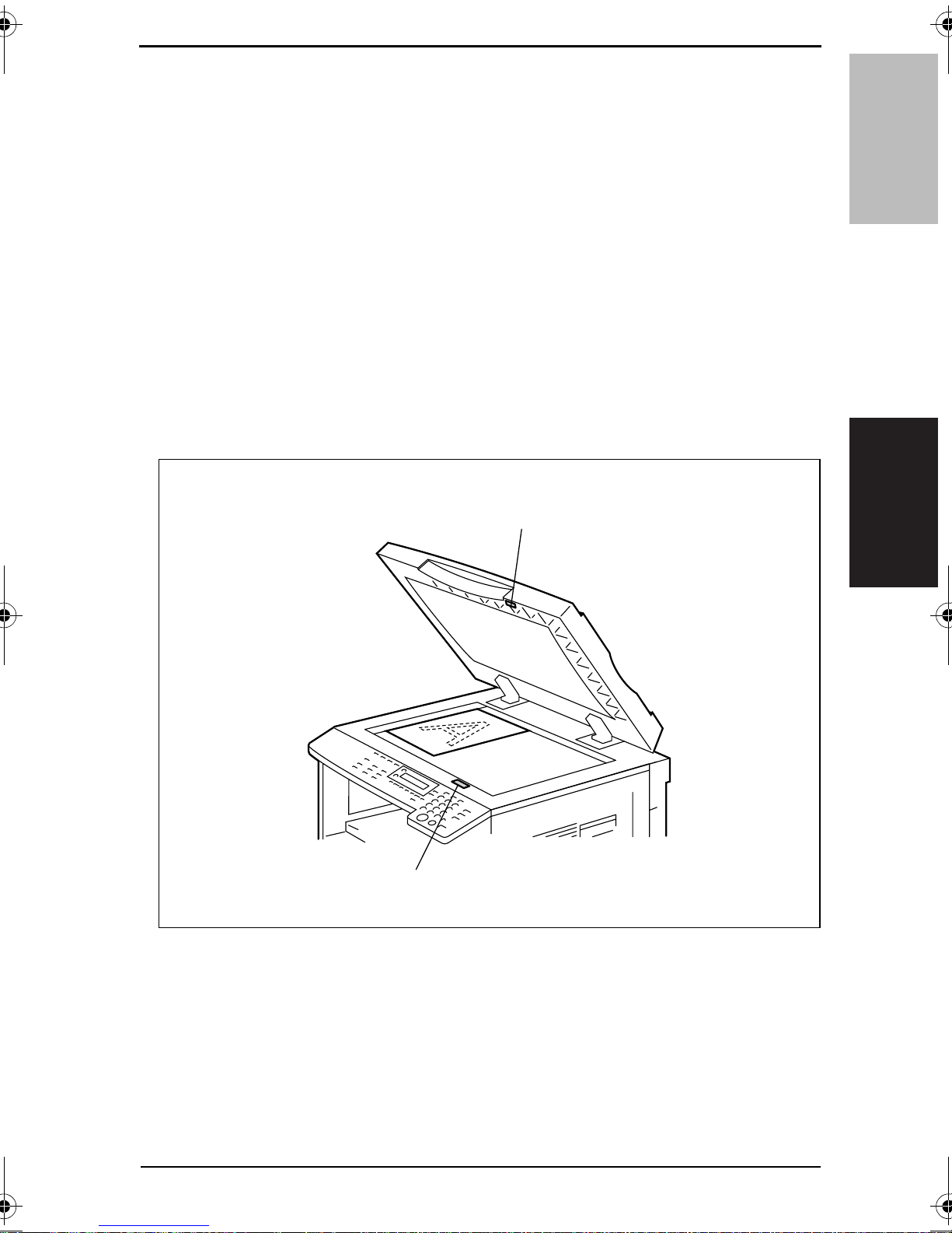
2.7 Raised/Lowered Position Detection Mechanism
• There is a magnet installed in the ADF body to allow the copier to know that the ADF is
raised or lowered.
• This magnet actuates the Size Reset Switch on the copier.
Magnet
DF-502Composition/Operation
Size Reset Switch (S5)
4034M521AA
9

2. Automatic Document Feeder (DF-502) Theory of Operation Ver. 1.0 Apr. 2005
DF-502
Composition/Operation
Blank page
10
 Loading...