

Page 1

SERVICE MANUAL
Models
DF318/DF-320
APRIL 2004
CSM-DF318/DF320
KONICA MINOLTA BUSINESS SOLUTIONS U.S.A., INC.
Page 2

Page 3

DF318/DF320
SERVICE MANUAL
APRIL 2004
Page 4

IMPORTANT NOTICE
Because of the possible hazards to an inexperienced
person servicing this equipment, as well as the risk of
damage to the equipment, Konica Minolta Business
Solutions U.S.A., Inc. strongly recommends that all
servicing be performed by Konica Minolta-trained service technicians only.
Changes may have been made to this equipment to
improve its performance after this service manual was
printed. Accordingly, Konica Minolta Business Solutions
U.S.A., Inc., makes no representations or warranties,
either expressed or implied, that the information contained in this service manual is complete or accurate. It
is understood that the user of this manual must assume
all risks or personal injury and/or damage to the equipment while servicing the equipment for which this service manual is intended.
Corporate Publications Department
© 2004, KONICA MINOLTA BUSINESS SOLUTIONS U.S.A. , INC.
All rights reserved.
Printed in U.S.A.
Page 5

CONTENTS
CONTENTS
SAFETY AND IMPORTANT WARNING ITEMS
Refer to the 7145/7235/7228/7222 service manual on page . . . . . . . . . . . . . . . . . . . . . . . . . . . . . . . . . . . S-1
I OUTLINE
1. DF-318/DF-320 PRODUCT SPECIFICATIONS . . . . . . . . . . . . . . . . . . . . . . . . . . . . . . . . . . . . . . . . . . 1-1
2. CENTER CROSS-SECTIONAL DIAGRAM . . . . . . . . . . . . . . . . . . . . . . . . . . . . . . . . . . . . . . . . . . . . . 1-3
3. DRIVE SYSTEM DIAGRAM . . . . . . . . . . . . . . . . . . . . . . . . . . . . . . . . . . . . . . . . . . . . . . . . . . . . . . . . . 1-4
3.1 Paper feed drive section . . . . . . . . . . . . . . . . . . . . . . . . . . . . . . . . . . . . . . . . . . . . . . . . . . . . . . . . 1-4
3.2 Conveyance/Paper exit drive section . . . . . . . . . . . . . . . . . . . . . . . . . . . . . . . . . . . . . . . . . . . . . . 1-4
3.3 Reverse drive section . . . . . . . . . . . . . . . . . . . . . . . . . . . . . . . . . . . . . . . . . . . . . . . . . . . . . . . . . . 1-5
II UNIT EXPLANATION
1. PAPER FEED/REVERSAL/EXIT SECTION. . . . . . . . . . . . . . . . . . . . . . . . . . . . . . . . . . . . . . . . . . . . . 2-1
1.1 Composition. . . . . . . . . . . . . . . . . . . . . . . . . . . . . . . . . . . . . . . . . . . . . . . . . . . . . . . . . . . . . . . . . . 2-1
1.2 Operation. . . . . . . . . . . . . . . . . . . . . . . . . . . . . . . . . . . . . . . . . . . . . . . . . . . . . . . . . . . . . . . . . . . . 2-2
1.2.1 Single sided original mode . . . . . . . . . . . . . . . . . . . . . . . . . . . . . . . . . . . . . . . . . . . . . . . . . . 2-2
1.2.2 Double sided original mode . . . . . . . . . . . . . . . . . . . . . . . . . . . . . . . . . . . . . . . . . . . . . . . . . 2-6
1.2.3 Mixed original mode and Z-folded original mode . . . . . . . . . . . . . . . . . . . . . . . . . . . . . . . . 2-14
1.2.4 Original size detection . . . . . . . . . . . . . . . . . . . . . . . . . . . . . . . . . . . . . . . . . . . . . . . . . . . . 2-15
1.2.5 Allowed size combination . . . . . . . . . . . . . . . . . . . . . . . . . . . . . . . . . . . . . . . . . . . . . . . . . . 2-15
1.2.6 Control of the verification stamp for FAX . . . . . . . . . . . . . . . . . . . . . . . . . . . . . . . . . . . . . . 2-16
I OUTLINEII UNIT EXPLANATIONIII DIS./ASSEMBLY
III DISASSEMBLY/ASSEMBLY
1. PAPER FEED/REVERSAL/EXIT SECTION. . . . . . . . . . . . . . . . . . . . . . . . . . . . . . . . . . . . . . . . . . . . . 3-1
1.1 Replacing the paper feed roller and the feed rubber. . . . . . . . . . . . . . . . . . . . . . . . . . . . . . . . . . . 3-1
1.2 Replacing the double feed prevention roller . . . . . . . . . . . . . . . . . . . . . . . . . . . . . . . . . . . . . . . . . 3-3
1.3 Replacing the read roller . . . . . . . . . . . . . . . . . . . . . . . . . . . . . . . . . . . . . . . . . . . . . . . . . . . . . . . . 3-4
1.4 Removing and reinstalling the paper dust removing brush . . . . . . . . . . . . . . . . . . . . . . . . . . . . . . 3-5
1.5 Replacing the verification stamp for FAX . . . . . . . . . . . . . . . . . . . . . . . . . . . . . . . . . . . . . . . . . . . 3-6
2. EXTERNAL SECTION . . . . . . . . . . . . . . . . . . . . . . . . . . . . . . . . . . . . . . . . . . . . . . . . . . . . . . . . . . . . . 3-7
2.1 Removing and reinstalling the RADF . . . . . . . . . . . . . . . . . . . . . . . . . . . . . . . . . . . . . . . . . . . . . . 3-7
i
Page 6

CONTENTS
I OUTLINE
II UNIT EXPLANATION
III DIS./ASSEMBLY
Blank page
ii
Page 7
DF-318/DF-320 PRODUCT SPECIFICATIONS
IOUTLINE
1. DF-318/DF-320 PRODUCT SPECIFICATIONS
A. Type
Type: Sheet-through Type reversible DF
B. Functions
Original size (for metric area): A3, B4, A4, A4R, B5, B5R, A5, A5R, 11 x 17, 8.5 x 14, 8.5 x 11
Original size (for inch area): 11 x 17, 8.5 x 14, 8.5 x 11, 8.5 x 11R, 5.5 x 8.5, 5.5 x 8.5R
A3, B4, A4, B5, B5R, B6R
• Mixing of original size possible.
Original type
Plain paper: 50g/m
Special paper: Original feed and conveyance ability may be inferior those of high-
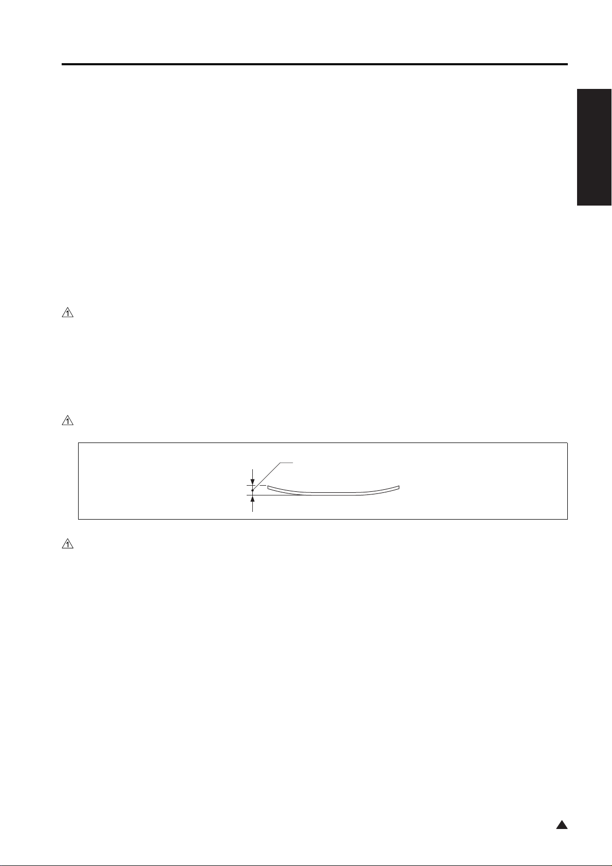
Original Curling (5 sheet): h = 10mm or less (80g/m
2
to 130g/m2 (13lbs to 34lbs), high-quality paper (DF-318)
2
35g/m
quality original mentioned above.
The following types of original cannot be used:
• OHP film, Blueprint masters, Offset masters, Bonded original
to 130g/m2 (13lbs to 34lbs), high-quality paper (DF-320)
2
or 20lbs high-quality paper)
h
I OUTLINE
2
Amount of originals to be stacked: 50 sheets max. (80g/m
(Original curling: 10mm or less)
80 sheets max. (80g/m
(Original curling: 1mm or less)
Original scan speed (A4 size): Single side mode: 45 sheets/minute
Double side mode: 34 sheets/minute
Original feed layout: Face-up placement, centre standard
Original image read position: At the slit glass section
or 20lbs high-quality paper)
2
or 20lbs high-quality paper)
C. Machine Data
Power source: 24VDC/5V (supplied from the main body)
Power consumption: Maximum 100VA
Weight: Approx. 11kg (including about 1.1kg for platen)
Dimensions: 576mm (W) x 502mm (D) x 100mm (H)
(Excluding the original feed tray)
1-1
1
Page 8

DF-318/DF-320 PRODUCT SPECIFICATIONS
D. Maintenance
Maintenance: Same as the main body
E. Operating Environment
I OUTLINE
Temperature: 10°C to 30°C (50°F to 86°F)
Humidity: 10% RH to 80% RH
Note:
• The information herein may be subject to change for improvement without notice.
1-2
Page 9
CENTER CROSS-SECTIONAL DIAGRAM
2. CENTER CROSS-SECTIONAL DIAGRAM
[10]
[8]
[9]
[11]
[12]
I OUTLINE
[3]
[7]
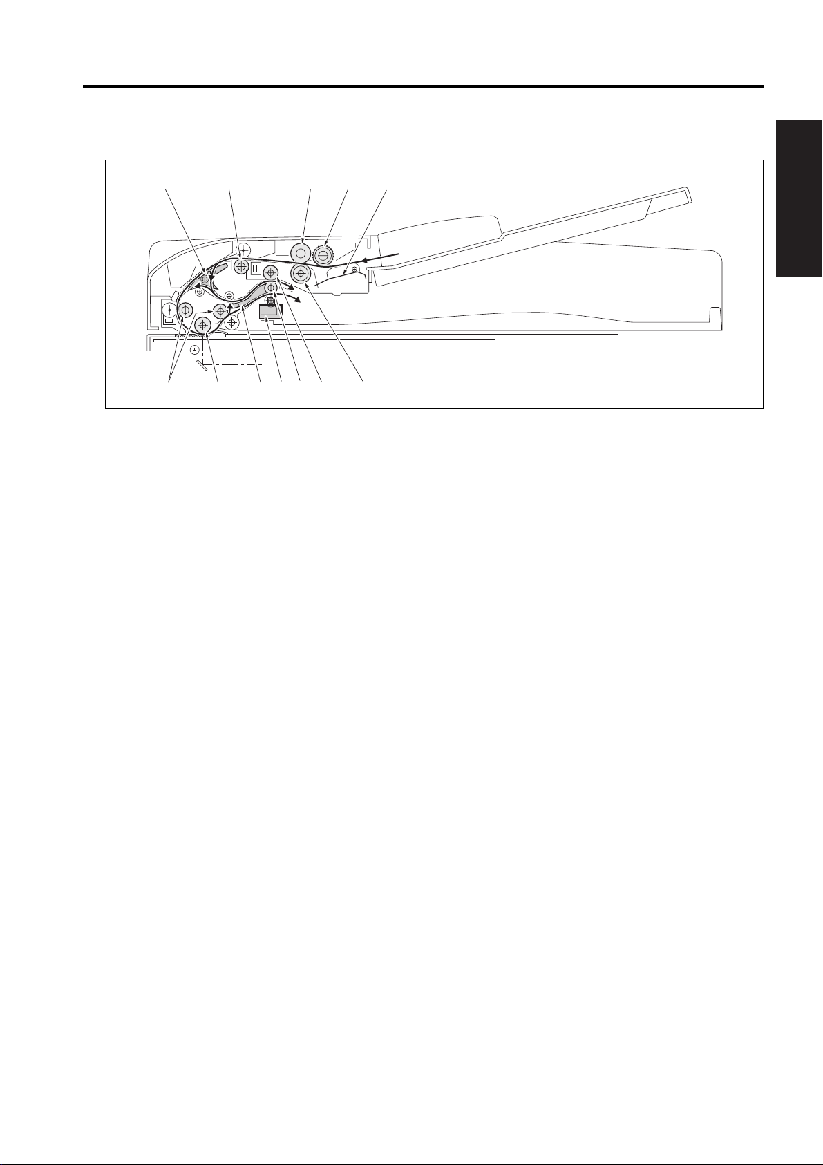
[1] Double feed prevention roller [7] Conveyance roller
[2] Reverse roller [8] Reverse guide
[3] Paper exit roller [9] Registration roller
[4] SD303 (Stamp solenoid) [10] Feed roller
[5] Paper exit guide [11] Paper feed roller
[6] Read roller [12] Paper up/down plate
[6]
[5] [4]
[1][2]
1-3
Page 10
DRIVE SYSTEM DIAGRAM
3. DRIVE SYSTEM DIAGRAM
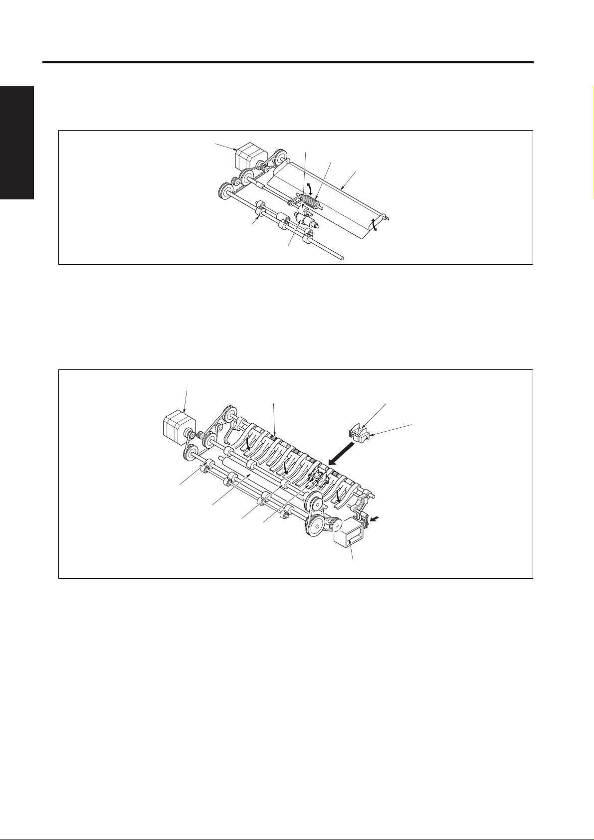
3.1 Paper Feed Drive Section
I OUTLINE
3.2 Conveyance/Paper Exit Drive Section
[3]
[2]
[1] Double feed prevention roller [4] Feed roller
[2] Registration roller [5] Paper feed roller
[3] M301 (Original feed motor) [6] Paper up/down plate
[7]
[8]
[4]
[5]
[6]
[1]
[9]
[1]
[6]
[5]
[4]
[3]
[2]
[1] SD303 (Stamp solenoid) [6] Before-read roller
[2] SD301 (Paper exit solenoid) [7] M302 (Original conveyance motor)
[3] Paper exit guide [8] Paper exit roller
[4] After-read roller [9] Verification stamp for FAX
[5] Read roller
1-4
Page 11
DRIVE SYSTEM DIAGRAM
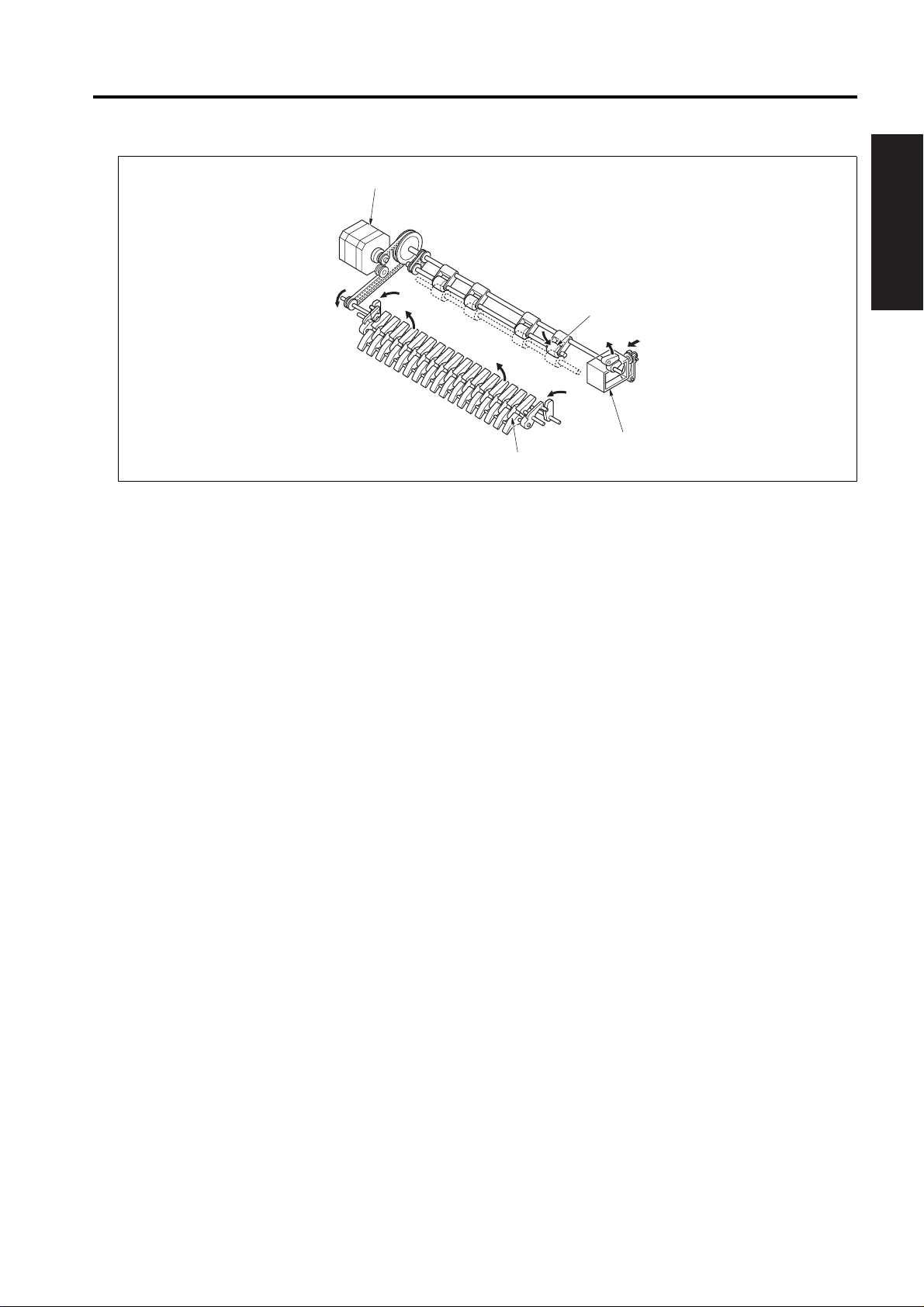
3.3 Reverse Drive Section
[3]
[4]
[1]
[2]
[1] SD302 (Pressure roller solenoid) [3] M303 (Original reverse motor)
[2] Reverse guide [4] Reverse roller
I OUTLINE
1-5
Page 12

DRIVE SYSTEM DIAGRAM
I OUTLINE
Blank page
1-6
Page 13
PAPER FEED/REVERSAL/EXIT SECTION
II UNIT EXPLANATION
1. PAPER FEED/REVERSAL/EXIT SECTION
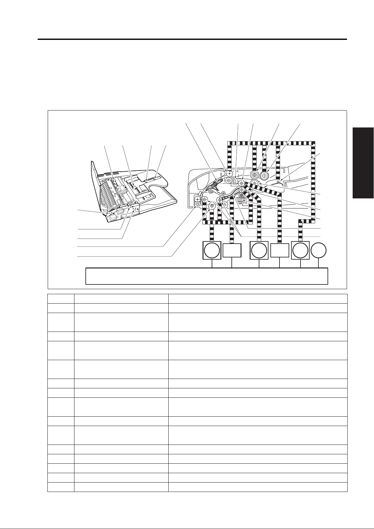
1.1 Composition
[16]
[17] [18] [19] [20] [21]
[13]
[12]
[11]
[10]
[9]
[8]
[7]
Symbol Name Function or method
[1] Paper up/down plate Lift the original to the paper feed roller while feeding original
[2] Double feed prevention roller Double feed prevention of original
[3] Paper exit roller Original exit
[4] SD303 (Stamp solenoid) Affix the verification stamp
[5] Paper exit guide Switching-over of the conveyance path original exited
[6] Conveyance roller Original conveyance
[7] Read roller Original conveyance
[8] PS309
(Original conveyance sensor)
[9] PS301 (No original sensor) No paper detection in the paper feed tray
[10] PS304
(Cover open/close sensor)
[11] PS303 (DF open/close sensor) RADF open/close detection
[12] PS302 (Original exit sensor) Detection of original exited
[13] VR301 (Original size VR) Detection of original size in the main scanning direction
[14] PS305 (Original size sensor /1) Detection of original size in the sub-scanning direction
[15] PS306 (Original size sensor /2) Detection of original size in the sub-scanning direction
[14]
[15]
M303M302 SD301 SD302
DFDB
Torque limiter method
24VDC drive
SD301 (Paper exit solenoid) open/close method
Original detection just before the read section
Detection of the open/close of the open/close cover
M301
FM301
[1]
[2]
[3]
[4]
[5]
[6]
II UNIT EXPLANATION
2-1
Page 14
PAPER FEED/REVERSAL/EXIT SECTION
Symbol Name Function or method
[16] Reverse guide Switching-over of the conveyance path for original
[17] Registration roller Original skew correction, original conveyance
[18] PS308
(Original registration sensor)
[19] Reverse roller Reversal of original
[20] Feed roller Feeding of original
[21] Paper feed roller Picking-up of original
DFDB DF drive board RADF drive board
M301 Original feed motor Driving of original feed section
M302 Original conveyance motor Driving of original conveyance section
II UNIT EXPLANATION
M303 Original reverse motor Driving of original reversal section
FM301 Cooling fan Cooling of M302 (Original conveyance motor)
SD301 Paper exit solenoid Opening/closing of the paper exit guide
SD302 Pressure roller solenoid Pressing/releasing of the reverse roller
Original detection just before the registration roller
The control is made by the main body's CB (Main body control
board).
24VDC stepping motor
24VDC stepping motor
24VDC stepping motor
24VDC drive
24VDC drive
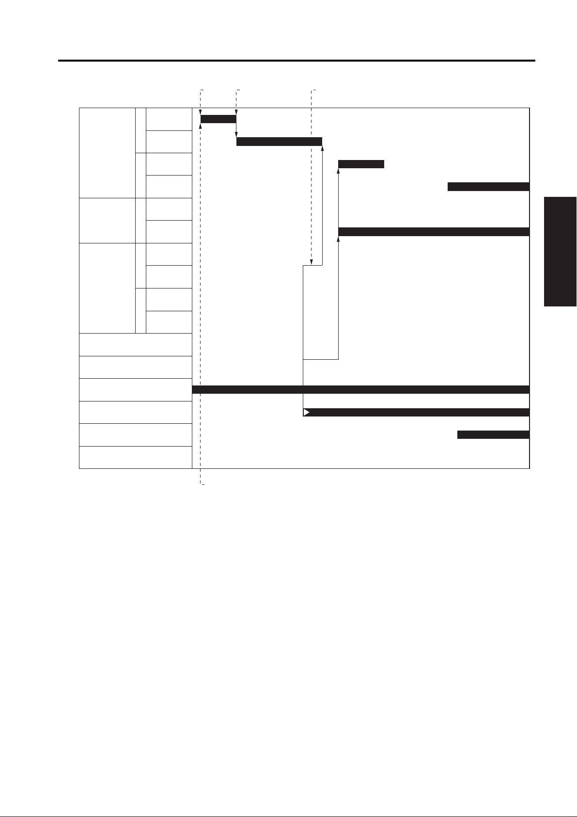
1.2 Operation
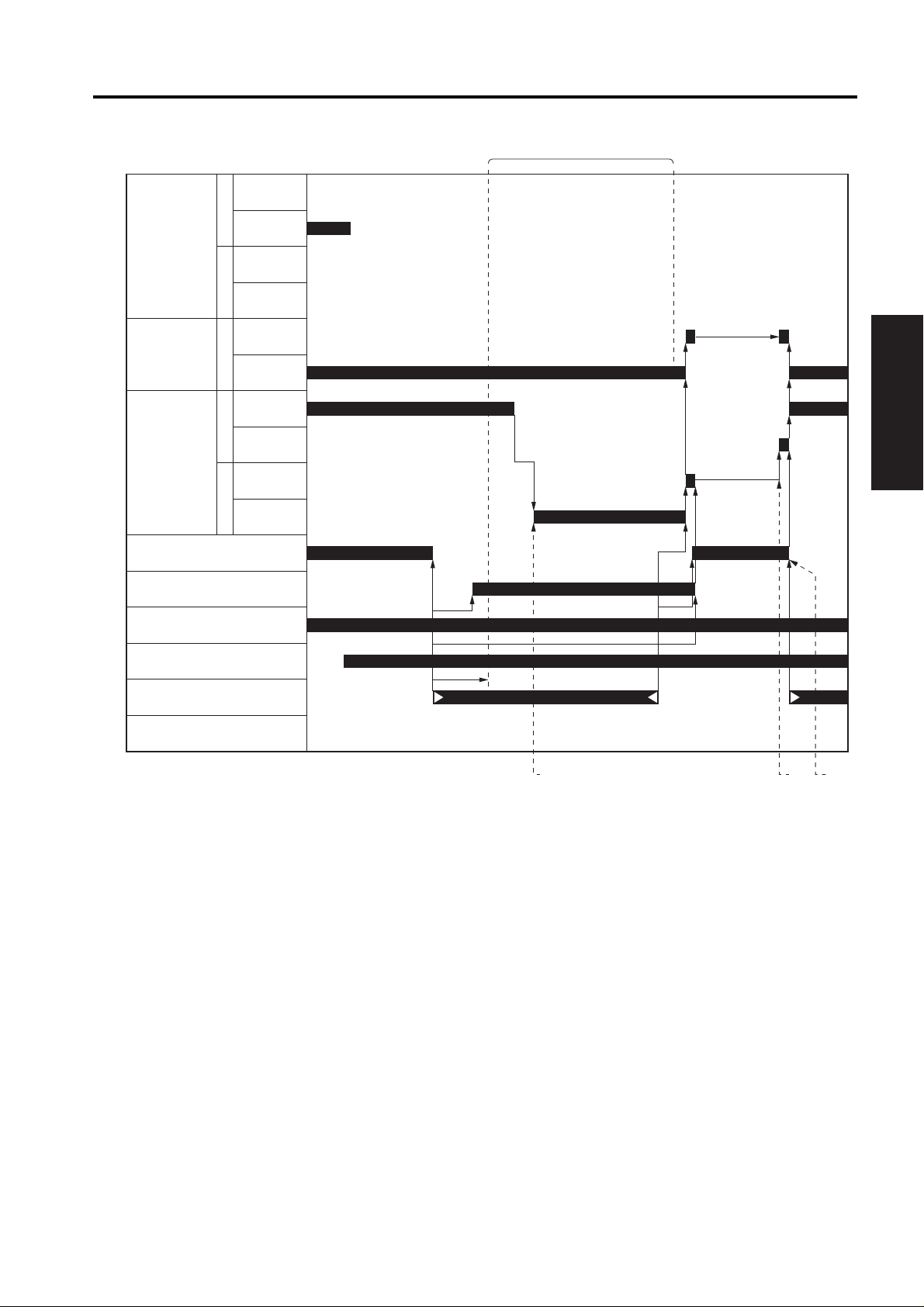
1.2.1 Single sided original mode
A. The original set in the paper feed tray is pressed against the paper feed roller by the paper up/
down plate, and then struck against the registration roller by the paper feed roller and the feed
roller to form a loop. The amount of the loop is controlled according to a value registered by
the timer after the leading edge of the original turns on the PS308 (Original registration sen-
sor).
[4]
[2]
[5]
[1]
[3]
[1] Paper up/down plate [4] Feed roller
[2] PS308 (Original registration sensor) [5] Paper feed roller
[3] Registration roller
2-2
Page 15
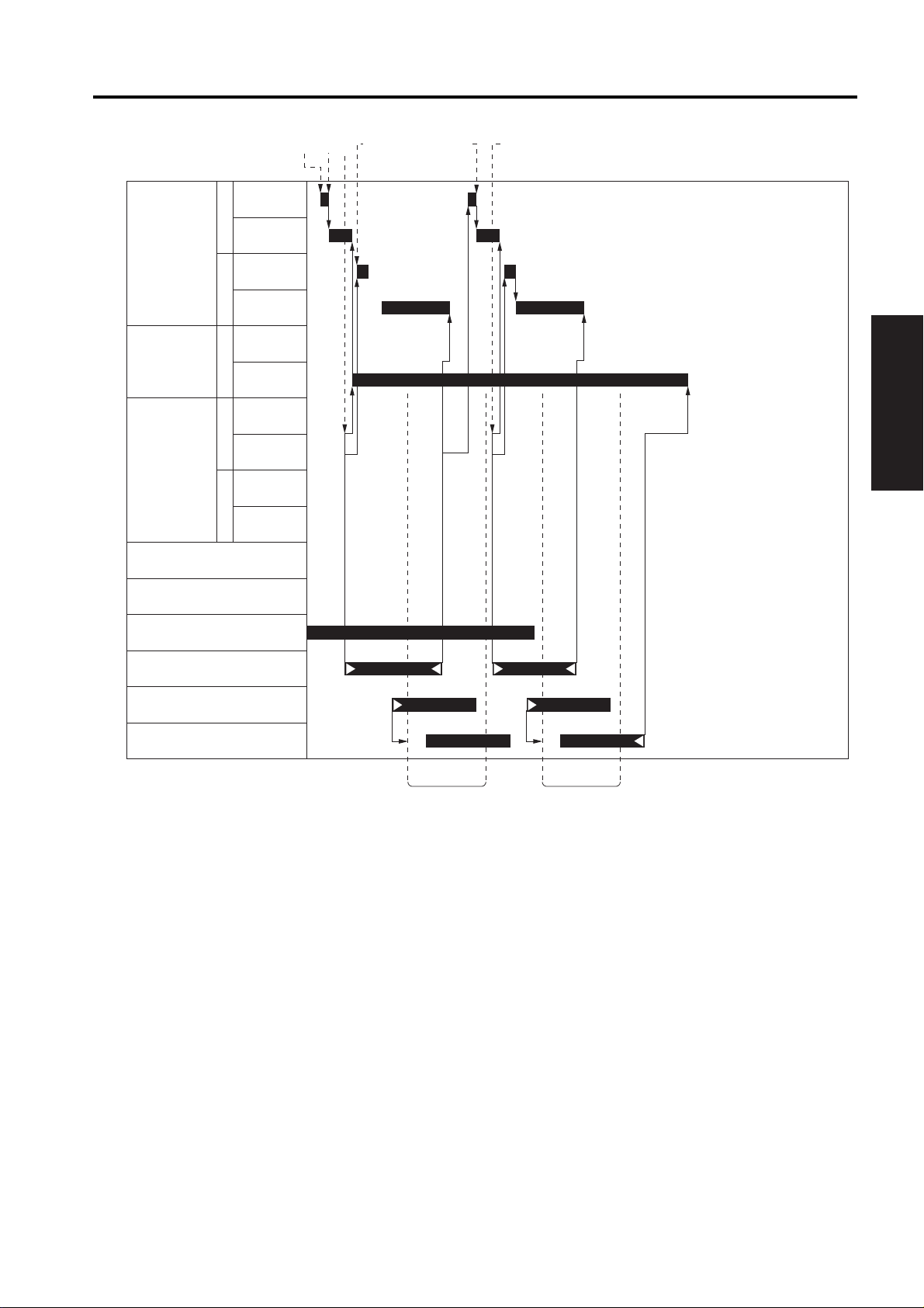
PAPER FEED/REVERSAL/EXIT SECTION
[4][3][2]
M301
(Original
feed motor)
M302 (Original
conveyance
motor)
M303 (Original
reverse motor)
SD302 (Pressure roller solenoid)
SD301 (Paper exit solenoid)
PS301 (No original sensor)
100mm/s
F
250mm/s
460mm/s
R
230mm/s
230mm/s
F
460mm/s
230mm/s
F
460mm/s
460mm/s
R
230mm/s
II UNIT EXPLANATION
PS308 (Original registration sensor)
PS309 (Original conveyance sensor)
PS302 (Original exit sensor)
[1]
[1] START button ON [3] Pre-feed
[2] Paper up/down plate, pressed down [4] Loop formation
2-3
Page 16
PAPER FEED/REVERSAL/EXIT SECTION
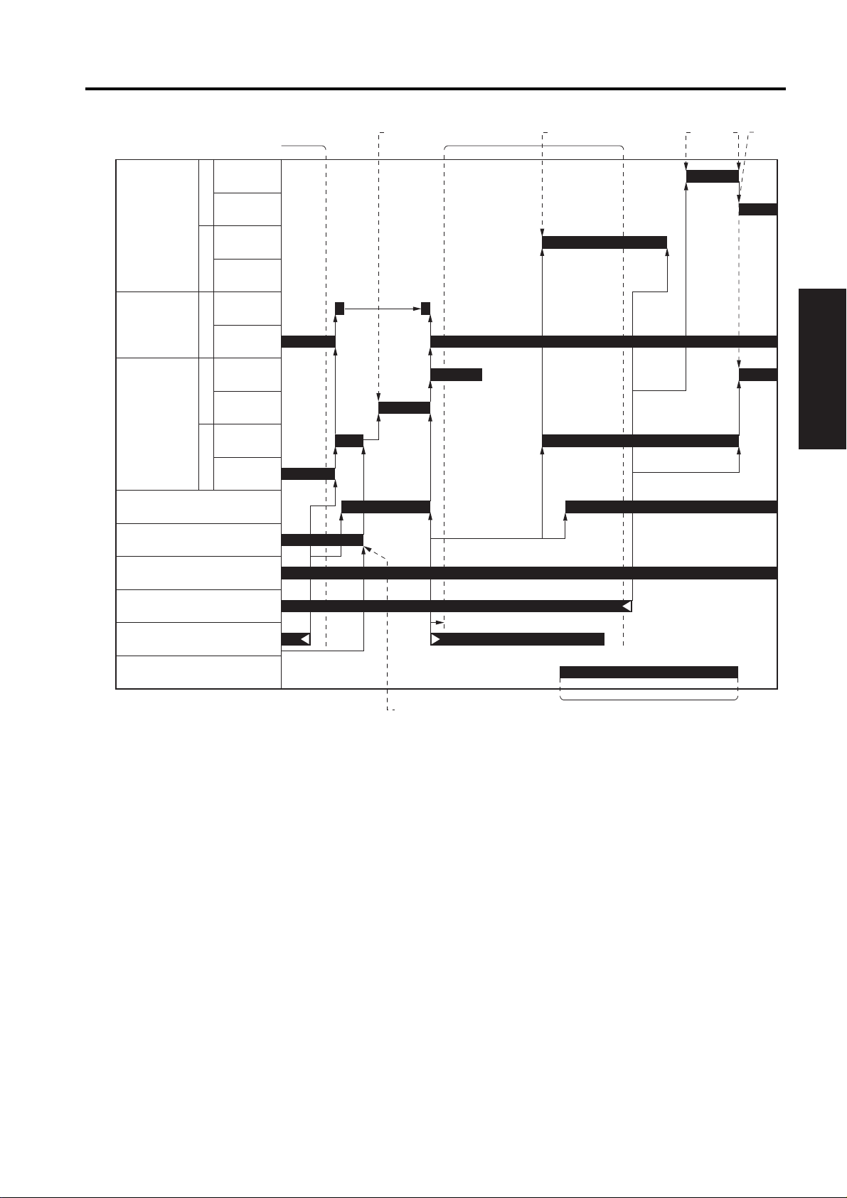
B. After the loop is formed at the registration roller section, the M301 (Original feed motor) rotates
backward and the M302 (Original conveyance motor) re-feeds paper. The original is scanned at
the slit glass section according to a value registered by the timer after the leading edge of the
original turns on the PS 309 (Original conveyance sensor). At this time, if there are originals in
the tray, the next original is pre-fed according to a value registered by the timer after the trail-
ing edge of the preceding original turns off the PS308 (Original registration sensor). When the
trailing edge of the last original turns off the PS309 (Original conveyance sensor), the M301
goes off. When the PS302 (Original exit sensor) detects the trailing edge of the last original, the
M302 goes off to finish the scanning of the original.
II UNIT EXPLANATION
[4]
[5]
[1]
[3]
[1] Paper exit roller [4] Next original
[2] Paper exit guide [5] Paper exit tray
[3] Slit glass (Original reader)
[2]
2-4
Page 17
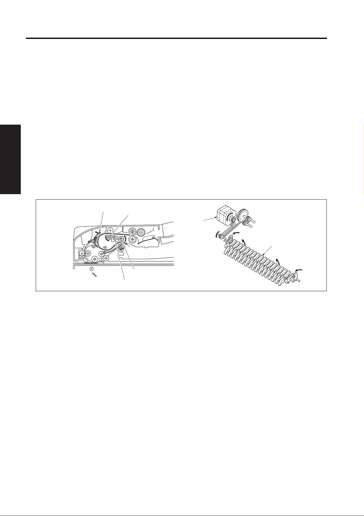
PAPER FEED/REVERSAL/EXIT SECTION
[6][4][3][2][1] [7]
M301
(Original
feed motor)
M302 (Original
conveyance
motor)
M303 (Original
reverse motor)
SD302 (Pressure roller solenoid)
SD301 (Paper exit solenoid)
PS301 (No original sensor)
100mm/s
F
250mm/s
460mm/s
R
230mm/s
460mm/s
F
230mm/s
230mm/s
F
460mm/s
R
460mm/s
230mm/s
II UNIT EXPLANATION
PS308 (Original registration sensor)
PS309 (Original conveyance sensor)
PS302 (Original exit sensor)
[5] [8]
[1] Turning on the START button to press
down the paper up/down plate
[2] Pre-feeding [7] Loop formation of the 2nd paper
[3] Loop formation of the 1st paper [8] Scanning of the 2nd original
[4] Re-feeding of the 1st paper
[5]
Scanning of the 1st paper
[6]
Pre-feeding of the 2nd paper
2-5
Page 18
PAPER FEED/REVERSAL/EXIT SECTION
1.2.2 Double sided original mode
A. In the double sided original mode, the original is reversed and its back side is scanned first,
and then the front side is scanned before being straight ejected. Copying originals in their
scanned order may cause the copied sheets to get out of their specified pagination. To avoid
this, image processing is used for page alignment. The original set in the paper feed tray is
pressed against the paper feed roller by the paper up/down plate, and then struck against the
registration roller by the paper feed roller and the feed roller to form a loop. The amount of the
loop is controlled according to a value registered by the timer after the leading edge of the
original turns on the PS308 (Original registration sensor). After the loop is formed at the regis-
tration roller section, the M301 (Original feed motor) rotates backward to re-feed paper. Upon
backward rotation of the M301, the M303 (Original reverse motor) also rotates backward to
open the reverse guide and convey the original to the reverse roller. The reverse roller can
release pressure through the SD302 (Roller pressure solenoid). It turns on the SD302 (Press-
ing by reverse roller) according to the value registered by the timer after the PS308 is turned
II UNIT EXPLANATION
on to convey the original to the paper exit tray side.
[3]
[4]
[5]
[3]
[1]
[2]
[1] Reverse roller [3] Registration roller
[2] PS308 (Original registration sensor) [4] M303 (Original reverse motor)
[3] Reverse guide
2-6
Page 19
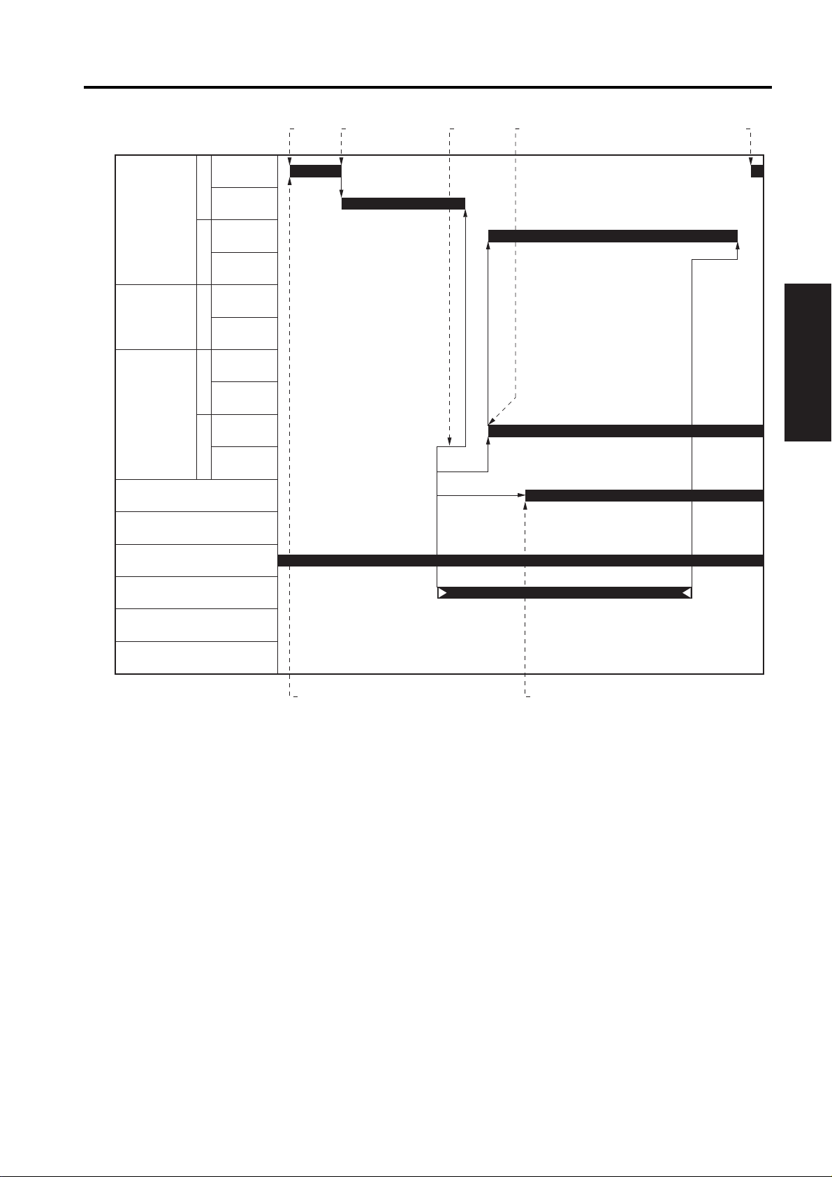
PAPER FEED/REVERSAL/EXIT SECTION
[4] [5][3] [7][2]
M301
(Original
feed motor)
M302 (Original
conveyance
motor)
M303 (Original
reverse motor)
SD302 (Pressure roller solenoid)
SD301 (Paper exit solenoid)
PS301 (No original sensor)
100mm/s
F
250mm/s
460mm/s
R
230mm/s
460mm/s
F
230mm/s
230mm/s
F
460mm/s
460mm/s
R
230mm/s
II UNIT EXPLANATION
PS308 (Original registration sensor)
PS309 (Original conveyance sensor)
PS302 (Original exit sensor)
[1]
[1]
START button ON
[2]
Paper up/down plate, pressed down
[3] Pre-feed [6] Pressing by the reverse roller
[4] Loop formation [7] Pressing of the 2nd original up/down plate
[5] Switching of the reverse guide to the
[6]
reverse section side
2-7
Page 20

PAPER FEED/REVERSAL/EXIT SECTION
B. According to the value registered by the timer after the PS308 (Original registration sensor)
detects the trailing edge of the original, the M302 (Original conveyance motor) and the M303
(Original reverse motor) rotate forward to reverse the original and convey the back side to the
slit glass section. The reverse guide is closed by the forward rotation of the M303 and the flap-
per[4] is opened by the rigidity of the original. As a result, the original is guided to the convey-
ance roller. At this time, if there is a succeeding original in the tray, it is pre-fed according to
the value registered by the timer after the trailing edge of the preceding original turns off the
PS308 (Original registration sensor).
[4]
II UNIT EXPLANATION
[3]
[5] [6] [7]
[2]
[1]
[1] Reverse roller [5] Reverse guide
[2] PS308 (Original registration sensor) [6] Next original
[3] Conveyance roller [7] Paper exit tray
[4] Flapper
2-8
Page 21
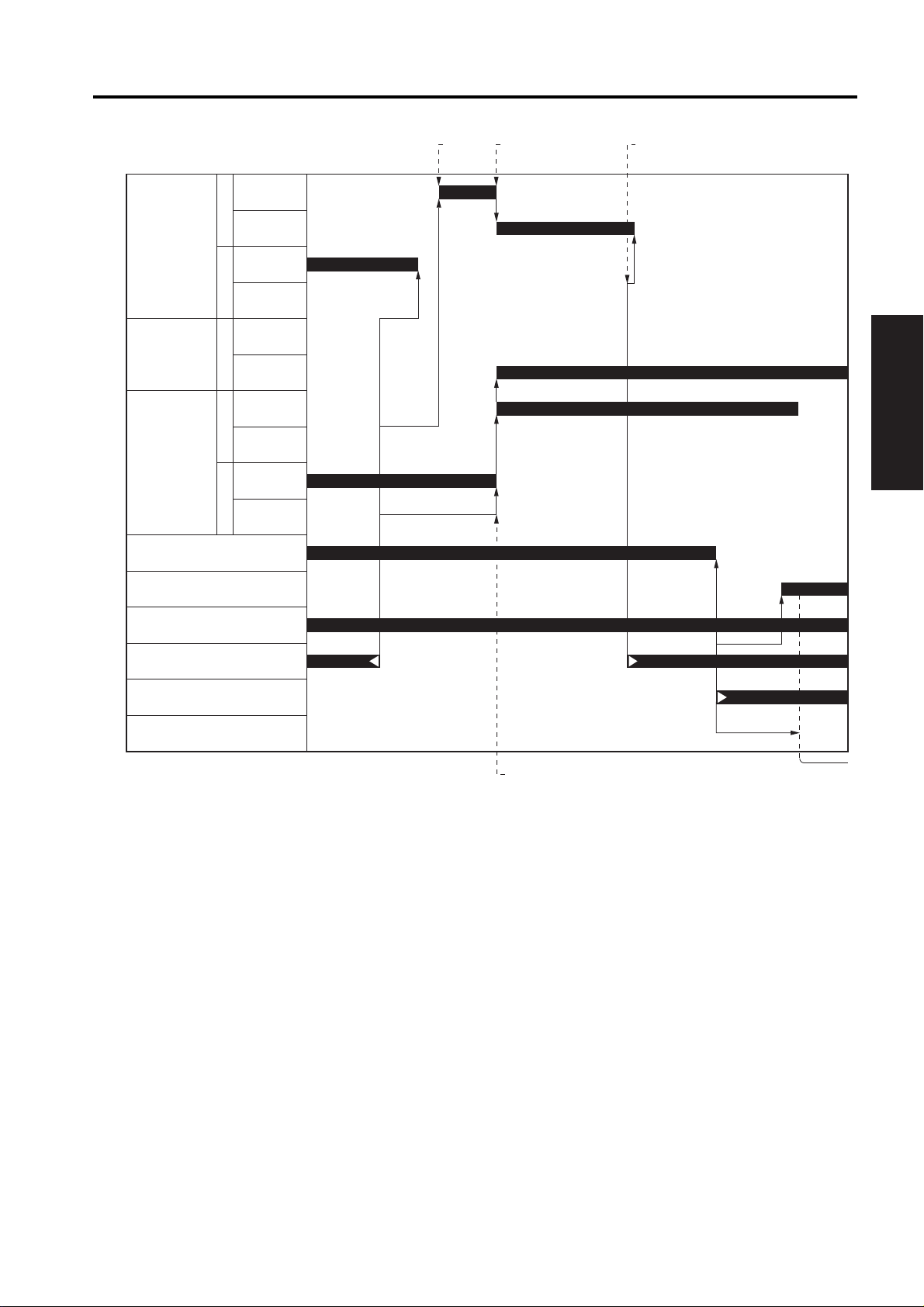
PAPER FEED/REVERSAL/EXIT SECTION
M301
(Original
feed motor)
M302 (Original
conveyance
motor)
M303 (Original
reverse motor)
SD302 (Pressure roller solenoid)
SD301 (Paper exit solenoid)
100mm/s
F
250mm/s
460mm/s
R
230mm/s
460mm/s
F
230mm/s
230mm/s
F
460mm/s
460mm/s
R
230mm/s
[2][1]
[4]
II UNIT EXPLANATION
PS301 (No original sensor)
PS308 (Original registration sensor)
PS309 (Original conveyance sensor)
PS302 (Original exit sensor)
[1]
Pressing of the 2nd original up/down plate
[2]
Pre-feeding of the 2nd original
[3] Reversing of the 1st original
(from front to back)
[3]
[4]
Loop formation of the 2nd original
[5]
Scanning of the back of the 1st original
[5]
2-9
Page 22

PAPER FEED/REVERSAL/EXIT SECTION
C. According to a value registered by the timer after the leading edge of the original turns on the
PS 309 (Original conveyance sensor), the back side of the original is scanned at the slit glass
section. At this time, the SD301 (Paper exit solenoid) is turned on to close the paper exit guide,
and a original the back side of which has been scanned is conveyed to the reverse roller. The
SD301 is turned on according to a value registered by the timer after the leading edge of the
original turns on the PS309. Paper conveyed to the reverse roller switches back and conveys
again an original to the conveyance roller, thus replacing the back side of the original with its
front side. Since the leading and trailing edges of an original larger than B5R is overlapped
each other while in switching back at this reversal section, the SD302 (Roller pressure sole-
noid) is turned off to release the pressure of the reverse roller.
II UNIT EXPLANATION
[7]
[8]
[6]
[5]
[1]
[4]
[3]
[1] Reverse roller [5] PS309 (Original conveyance sensor)
[2] Paper exit guide [6] Conveyance roller
[3] Read roller [7] Flapper
[4] Slit glass [8] Next original
[2]
2-10
Page 23
PAPER FEED/REVERSAL/EXIT SECTION
[1]
M301
(Original
feed motor)
M302 (Original
conveyance
motor)
M303 (Original
reverse motor)
SD302 (Pressure roller solenoid)
SD301 (Paper exit solenoid)
PS301 (No original sensor)
100mm/s
F
250mm/s
460mm/s
R
230mm/s
460mm/s
F
230mm/s
230mm/s
F
460mm/s
460mm/s
R
230mm/s
II UNIT EXPLANATION
PS308 (Original registration sensor)
PS309 (Original conveyance sensor)
PS302 (Original exit sensor)
[1]
Scanning of the back of the 1st original
[2]
Switching-back of the 1st original
[2] [3] [4]
[3] Reversing of the 1st original
(from back to front)
[4] SD302 (Roller pressure solenoid) release
2-11
Page 24

PAPER FEED/REVERSAL/EXIT SECTION
D. According to a value registered by the timer after the leading edge of the original turns on the
PS309 (Original conveyance sensor), the scanning of the back of the original is made at the slit
glass section. Since the SD301 (Paper exit solenoid) is off at this time, the paper exit guide is
left open and the original the front of which has been scanned is conveyed to the paper exit
roller to be exited. While the back of the original is being scanned, the SD301 goes off accord-
ing to a value registered by the timer after the leading edge of the original turns on the PS309.
[6]
[5]
[7]
[4]
II UNIT EXPLANATION
[3]
[1] Paper exit roller [5] Next original
[2] Paper exit guide [6] Reverse roller
[3] Slit glass [7] Paper exit tray
[4] PS309 (Original conveyance sensor)
[2]
[1]
2-12
Page 25
PAPER FEED/REVERSAL/EXIT SECTION
M301
(Original
feed motor)
M302 (Original
conveyance
motor)
M303 (Original
reverse motor)
SD302 (Pressure roller solenoid)
SD301 (Paper exit solenoid)
100mm/s
F
250mm/s
460mm/s
R
230mm/s
460mm/s
F
230mm/s
230mm/s
F
460mm/s
460mm/s
R
230mm/s
[3][1]
[4] [5] [7] [8] [9]
II UNIT EXPLANATION
PS301 (No original sensor)
PS308 (Original registration sensor)
PS309 (Original conveyance sensor)
PS302 (Original exit sensor)
[6][2]
[1] Scanning of the back of the 1st original [5] Re-feeding of the 2nd original
[2] Switching of the paper exit guide in the
direction of the paper exit
[3] Reversing of the 1st original
(from back to front)
[6]
Exiting of the 1st original
[7]
Pressing of the 3rd original up/down plate
[8]
Pre-feeding of the 3rd original
[9]
Reversing of the 2nd original
(from front to back)[4] Scanning of the front of the 1st original
2-13
Page 26

PAPER FEED/REVERSAL/EXIT SECTION
1.2.3 Mixed original mode and Z-folded original mode
The mixed original mode supports both the same series original and the different series original. The oper-
ation of the original conveyance in the mixed original mode is the same as that of the normal double sided
original mode, regardless of a single sided mode or double sided mode.
Although the detection of original size in the normal mode is made at the time when the original is set in
the paper feed tray, the size detection in the mixed original mode, however, is made based on the length of
time when the original passes through the PS308 (Original registration sensor) while the original is being
sent from the paper feed tray to the reverse roller. The original detection like this is applicable to all origi-
nals.
In the Z-folded original mode, the same detection operation as that for the mixed original sizes mode is
made only on the first original to determine the original size. However, the normal operation of original con-
veyance is made for originals on and after the 2nd original.
II UNIT EXPLANATION
[1]
[2]
[1] Reverse roller [2] PS308 (Original registration sensor)
2-14
Page 27
PAPER FEED/REVERSAL/EXIT SECTION
1.2.4 Original size detection
A. Normal copy mode
(1) Main scanning direction
Detected by the value of resistance of the VR301 (Original size VR) that is interlocked with the posi-
tion of the guide plate above the paper feed tray.
(2) Sub-scanning direction
Detected by the combination of the PS305 (Original size sensor /1) and the PS306 (Original size sen-
sor 2/) when they are turned on and off.
B. Mixed original mode and Z-folded original mode
(1) Main scanning direction
The width of the largest original of the mixed original sizes is detected by the value of resistance of the
VR301 (Original size VR) that is interlocked with the position of the guide plate above the paper feed
tray.
(2) Sub-scanning direction
Detection is made based on the length of time when the original passes through the PS308 (Original
registration sensor).
II UNIT EXPLANATION
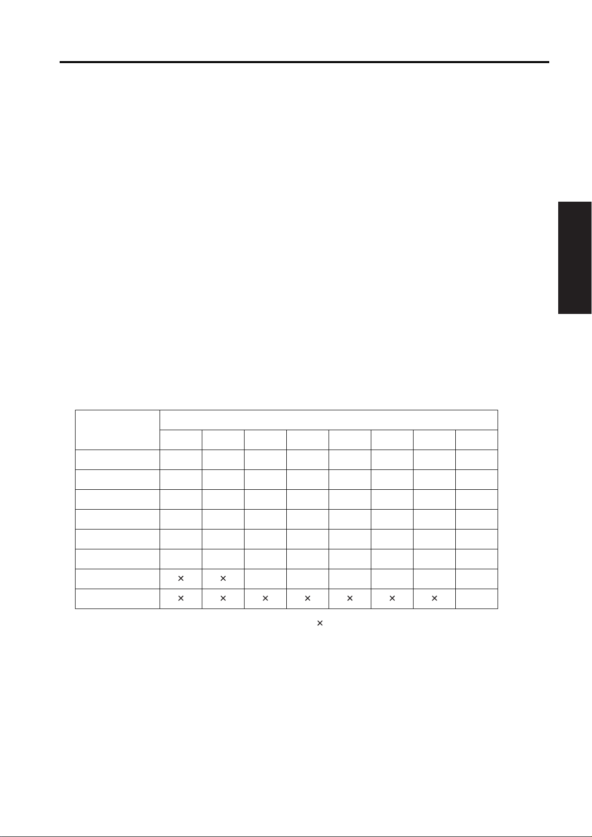
1.2.5 Allowed size combination
A. For metric area
Other originals Standard originals (the maximum original size detected by the guide plate)
A3 A4 B4 B5 A4R A5 B5R A5R
A3 {——————
A4 {——————
B4 ~~{————
B5 ~~{————
A4R ~~~~{——
A5 ~~~~{——
B5R ~~~~—
A5R
(: same size, {: same series, ~: different series, : no mixed loading, —: not supported)
2-15
Page 28
PAPER FEED/REVERSAL/EXIT SECTION
B. For inch area
Other originals Standard originals (the maximum original size detected by the guide plate)
11 x 17 8.5 x 11 8.5 x 14 8.5 x 11R 5.5 x 8.5 5.5 x 8.5R
11 x 17 {————
8.5 x 11 {————
8.5 x 14 ~~{{—
8.5 x 11R ~~{{—
5.5 x 8.5 ~~{{—
5.5 x 8.5R — — — — —
(: same size, {: same series, ~: different series, : no mixed loading, —: not supported)
II UNIT EXPLANATION
1.2.6 Control of the verification stamp for FAX
A. Operation of the verification stamp for FAX
In the FAX mode, a stamp showing that the original has been scanned is affixed on the original face
that has been scanned (for the double sided original mode, a stamp is affixed on front side only). The
stamp is driven by the SD303 (Stamp solenoid) and stamping is made when the original passes
through the paper exit roller. At this time, the M302 (Original conveyance motor) is turned off tempo-
rarily to stop the original.
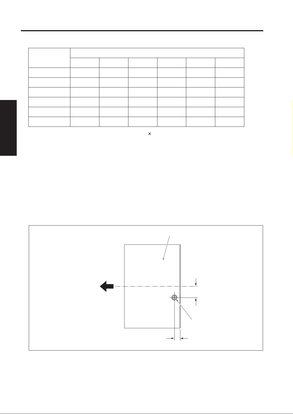
B. Stamping position
[5]
[4]
[1]
[2]
[3]
[1] 51mm ± 5mm [4] Direction of original conveyance
[2] Stamping position [5] Front of the original
[3] 10mm ± 2mm
2-16
Page 29
PAPER FEED/REVERSAL/EXIT SECTION
III DISASSEMBLY/ASSEMBLY
Caution:
• Make sure the power cord of the copier is
unplugged from the power outlet before dis-
assembly or assembly.
1. PAPER FEED/REVERSAL/ EXIT SECTION
1.1 Replacing the Paper Feed
Roller and the Feed Rubber
A. Periodically replaced parts/cycle
• Paper feed roller: Every 1,200,000 copies (once
for every 300,000 copies for actual durable
count) (7145)
• Paper feed roller: Every 1,000,000 copies (once
for every 300,000 copies for actual durable
count) (7235/7228/7222)
• Feed rubber: Every 960,000 copies (once for
every 250,000 copies for actual durable count)
(7145)
• Feed rubber: Every 1,000,000 copies (once for
every 250,000 copies for actual durable count)
(7235/7228/7222)
III DIS./ASSEMBLY
B. Procedure
1. Open the open/close cover.
2. Remove the 2 screws [1] and remove the paper
feed unit [2].
[2]
[1]
[2]
3-1
1
Page 30

PAPER FEED/REVERSAL/EXIT SECTION
3. Remove the 2 stop rings [1] and the 2 bearings
[2], and remove the paper feed roller assembly
[4] from the paper feed unit [3].
4. Remove the stop ring [5] and remove the bear-
ing [6].
5. Pull out the shaft [7] and remove the paper feed
roller [8].
6. Remove the 3 stop rings [9] and the bearing
[10]. Pull out the shaft [11] and remove the feed
roller [12].
7. Remove the feed rubber from the feed roller
[12].
Note:
• Be sure to install the paper feed roller so that the
one-way clutch comes to the rear side.
• Be sure to install the feed roller so that the one-
way clutch comes to the front side.
• When installing the feed rubber, take note of the
direction of the paint mark [13].
[5]
[1]
[6]
[2]
[8]
[9]
[4]
[1]
[2]
[7]
[3]
[13]
[11]
[12][10]
8. Reinstall the above parts following the removal
steps in reverse.
III DIS./ASSEMBLY
3-2
Page 31

PAPER FEED/REVERSAL/EXIT SECTION
1.2 Replacing the Double Feed
Prevention Roller
A. Periodically replaced parts/cycle
• Double feed prevention roller: Every 960,000
copies (once for every 250,000 copies for actual
durable count) (7145)
• Double feed prevention roller: Every 1,000,000
copies (once for every 250,000 copies for actual
durable count) (7235/7228/7222)
B. Procedure
1. Open the open/close cover.
2. Remove the paper feed unit.
3. Remove the double feed prevention roller unit
[1].
4. Remove the E-ring [1], and pull out the double
feed prevention roller [3] to remove it from the
shaft [2].
Note:
• Be sure to install the double feed prevention roller
[3] so that the paint mark [4] turns in the direction
shown in the drawing.
5. Reinstall the above parts following the removal
steps in reverse.
[1]
[2]
[3]
[1]
III DIS./ASSEMBLY
[1]
[4]
3-3
1
Page 32

PAPER FEED/REVERSAL/EXIT SECTION
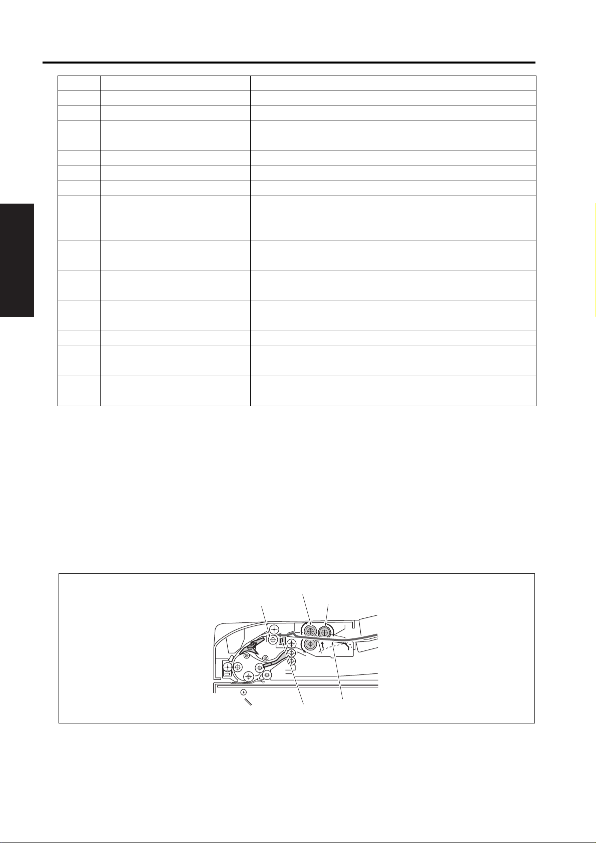
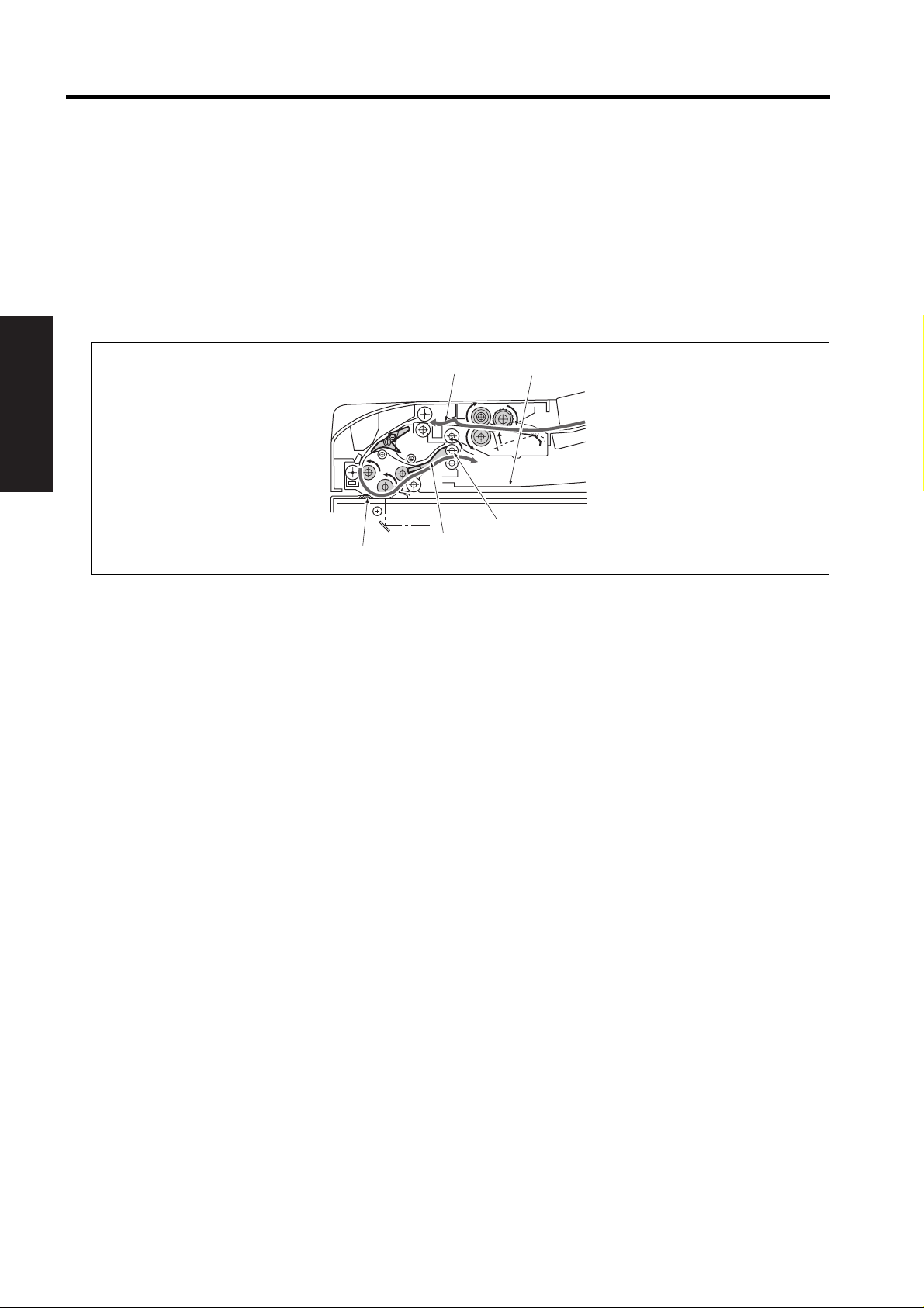
1.3 Replacing the Read Roller
A. Procedure
1. Open the RADF.
2. Remove the 3 screws [1], and remove the cover
[2].
[1]
[2]
[1]
3. Remove the screw [1], and remove the guide
[2].
4. Remove the 2 E-rings [3].
III DIS./ASSEMBLY
5. Slide up the read roller [1], and pull out the pin
[2] to remove the pulley [3].
6. Move the bearing [4] downward, then remove
the read roller [1].
7. Reinstall the above parts following the removal
steps in reverse.
[1]
[2]
[3]
[3]
[3]
[2]
[1]
Note:
• When the read roller gets soiled, clean it with
water or glass cleaner. Avoid use of alcohol for
cleaning. (Using alcohol may deteriorate the con-
veyance ability of the read roller.)
[1]
[4]
3-4
Page 33

PAPER FEED/REVERSAL/EXIT SECTION
1.4 Removing and Reinstalling
the Paper Dust Removing
Brush
A. Procedure
1. Open the open/close cover.
2. Remove the screw [1], and then remove the
paper dust removing brush [2].
3. Reinstall the above parts following the removal
steps in reverse.
[2]
[1]
III DIS./ASSEMBLY
3-5
Page 34

PAPER FEED/REVERSAL/EXIT SECTION
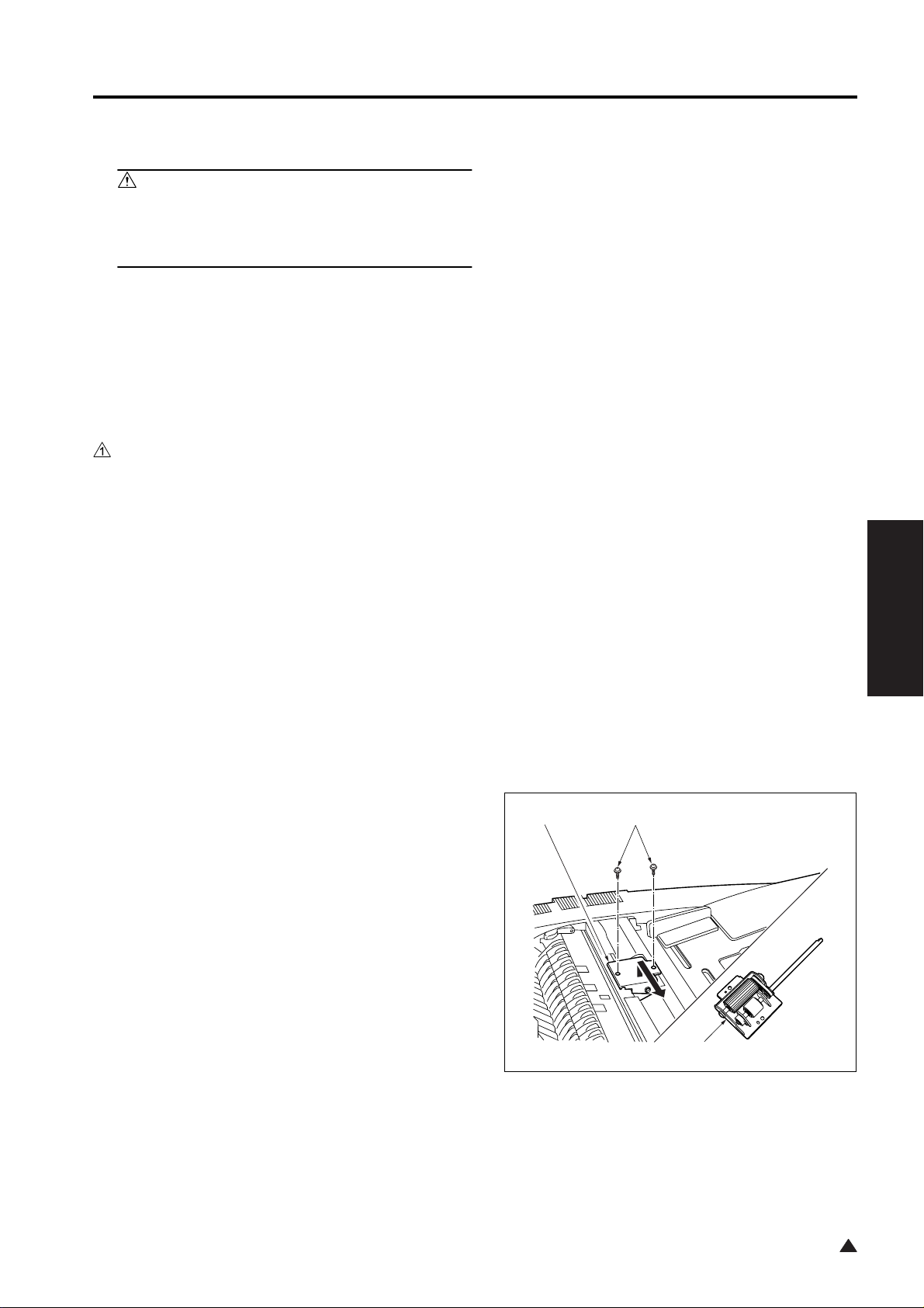
1.5 Replacing the Verification Stamp for FAX
A. Procedure
1. Open the RADF.
2. Open the paper exit tray [1].
3. Open the verification stamp for FAX unit [2] and
pull out the verification stamp [3].
4. Reinstall the above parts following the removal
steps in reverse.
Note:
• Be careful not to soil the paper exit roller with the
verification stamp.
• Be careful not to damage the plunger of the verifi-
cation stamp.
[3]
[2]
[1]
III DIS./ASSEMBLY
3-6
Page 35

EXTERNAL SECTION
2. EXTERNAL SECTION
2.1 Removing and Reinstalling the RADF
A. Procedure
1. Remove the 2 screws [1] and remove the cable
cover [2].
[2]
2. Remove the 2 screws [1] and the cable stay [2],
and then remove the 2 relay connectors.
[1]
III DIS./ASSEMBLY
[1]
[2]
3-7
Page 36

EXTERNAL SECTION
3. In the case of the DF-318
Loosen the 2 screws [1] and slide down the
stopper [2].
In the case of the DF-320
Remove the 2 screws [1] and remove the stop-
per [2].
4. Remove the screw [3].
[1][2]
[3]
III DIS./ASSEMBLY
5. Open the RADF [1] vertically.
6. Press the jam release lever [2] and open the
[3][1]
paper exit tray [3].
[2]
1
3-8
Page 37

7. Remove the screw [1] and remove the RADF [2]
while lifting it up.
8. Remove the paper exit tray [3] while lifting it up.
9. Reinstall the above parts following the removal
steps in reverse.
EXTERNAL SECTION
Note:
• After installing the RADF, be sure to conduct
“RADF height adjustment” and “RADF distortion
adjustment”.
[2]
[1][3]
III DIS./ASSEMBLY
3-9
Page 38

EXTERNAL SECTION
III DIS./ASSEMBLY
Blank page
3-10
Page 39

PARTS CATALOG
Model
DF-318
NOVEMBER 2002
KONICA BUSINESS TECHNOLOGIES, INC.
Page 40

Page 41

How to use this catalog
This parts catalog includes illustrations and part numbers for all replacement parts and assemblies used in this model.
Model-specific parts are identified in the illustrations with reference
numbers. Use the reference number to locate the corresponding part
number on the facing page.
Common hardware items, such as screws, nuts, washers, and pins, are
identified in the illustrations with reference letters. Use the reference letter to locate the corresponding part number on the hardware listing in the
lower right hand corner of the facing page.
If you know a part number, but don’t know where the part is used, use
the numerical index to determine the page number and reference number for that part. Because some common parts are used in several
places, there may be more than one entry. Refer to the illustrations to see
where the part may be used.
If you know a part’s description, but don’t know where to look to find
the part number, use the alphabetical index to determine likely page and
reference numbers. Then look at the illustrations to determine that you
have identified the correct part. Locate the part number using the listing
on the opposite page.
Retail pricing that appears with the numerical index, while valid when
this catalog was printed, is subject to change without notice. The prices
are only suggested prices and are provided only for reference. Dealers
may determine their own selling prices. For up-to-date pricing, refer to
current Konica price lists or contact the Konica Parts Distribution Center.
How to order parts
Use standard Konica parts ordering procedures to obtain these parts.
For ordering options, contact Konica’s Parts Distribution Center.
When ordering parts, be sure to specify part numbers exactly as listed in
this catalog.
NOTE: Electrical parts may include previously used components.
Model DF-318 Konica Business Technologies, Inc. Page iii
1st Edition November, 2002
Page 42

This page left blank intentionally.
Page iv Konica Business Technologies, Inc. Model DF-318
November, 2002 1st Edition
Page 43

How to use this catalog . . . . . . . . . . . . . . . . . . . . . . . . . iii
Contents . . . . . . . . . . . . . . . . . . . . . . . . . . . . 1
Housing . . . . . . . . . . . . . . . . . . . . . . . . . . . . 2
Rollers/Guides . . . . . . . . . . . . . . . . . . . . . . . . . . . . 4
Paper Feed Section . . . . . . . . . . . . . . . . . . . . . . . . . . . 6
Paper Transfer Section . . . . . . . . . . . . . . . . . . . . . . . . . 8
Paper Exit Section . . . . . . . . . . . . . . . . . . . . . . . . . . . 10
Open/Close . . . . . . . . . . . . . . . . . . . . . . . . . . . . 14
Paper Feed Tray . . . . . . . . . . . . . . . . . . . . . . . . . . . . 16
Wiring . . . . . . . . . . . . . . . . . . . . . . . . . . . . 18
Contents
Alphabetical Index . . . . . . . . . . . . . . . . . . . . . . . . . . . 21
Numerical Index . . . . . . . . . . . . . . . . . . . . . . . . . . . . 23
Model DF-318 Konica Business Technologies, Inc. Page 1
1st Edition November, 2002
Page 44

HOUSING
Page 2 Konica Business Technologies., Inc. Model DF-318
November, 2002 1st Edition
Page 45

REF. PART NUMBER DESCRIPTION
NO.
1 14GA12030 Front cover
2 13GL76080 Shaft holder/E
3 13GL45600 Positioning stopper/Front
4 13GL46160 Lock catch
5 14GA10110 Hinge/L
6 13GL46030 Original cover hinge
7 13GL46710 Hinge plate
8 13GL10191 Hinge mount plate/R
9 14GA12020 Rear cover
10 14GA46970 Solenoid set part/A
11 14GA-4801 Original exit tray assembly
12 13GL46100 Lock spring
13 14GA46080 Lock lever/A
14 13GL10320 Hinge stopper
15 14GA-1660 Hinge/R assembly
16 14GA-9010 RADF control unit
17 13GL10250 Hold spring/B
18 14GA90040 RADF wiring/4
19 13GL97081 Cleaning label/1
20 13GL10200 Hinge upper plate/R
HARDWARE
REF.
LTR.
a 00Z184061
b 00Z183041
c 00Z254101
d 00Z670306
e 00Z925103
f 00Z670406
g 00Z193041
h 00Z920034
i 00Z926251
j 00Z183042
k 00Z193062
m 00Z253081
PART
NUMBER
Model DF-318 Konica Business Technologies., Inc. Page 3
1st Edition November, 2002
Page 46

ROLLERS/GUIDES
Page 4 Konica Business Technologies., Inc. Model DF-318
November, 2002 1st Edition
Page 47

REF. PART NUMBER DESCRIPTION
NO.
1 13GL45151 Driving release roller/A
2 13GL15240 Reversal shaft holder
3 113620600 Pin (A)
4 13GL76590 Conveyance driving pulley/D (Z=42)
5 13GL40500 Slide sheet/A
6 466076020 Paper feeding shaft holder
7 13GL45840 Toque rotary spring
8 13GL77550 Driving reverse belt (L=60/96)
9 13GL76600 Conveyance driving pulley/E (Z=17)
10 13GL76610 Conveyance driving pulley/F (Z=17)
11 13GL40350 Connecting collar
12 13GL40341 Toque limiter/B
13 13GL-4050 Double feed preventive roller/A assembly
14 13GL10300 Rotary spring
15 13GL40050 Double feed preventive plate
16 13QA85510 Sensor/1
17 13GL45591 Electrify preventive sheet
18 13GL46661 Paper exit detecting plate
19 13GL40380 Stopper part/A
20 13GL-4041 Double feed preventive roller
21 14GA-1531 Solenoid/A assembly
22 13GL-4012 Paper feed guide plate/Lower assembly
23 13GL45210 Driving release lever/1
24 13GL40550 Conveyance auxiliary sheet
25 08AA85510 Photosensor
26 13GL46690 Neutralizing brush
27 13GL45200 Pressure spring
28 13GL45190 Pressure part
29 13GL40240 Double feed preventive spring
HARDWARE
REF.
LTR.
a 00Z194081
b 00Z926251
c 00Z193041
d 00Z921930
e 00Z193061
f 00Z670406
PART
NUMBER
Model DF-318 Konica Business Technologies., Inc. Page 5
1st Edition November, 2002
Page 48

PAPER FEED SECTION
Page 6 Konica Business Technologies., Inc. Model DF-318
November, 2002 1st Edition
Page 49

REF. PART NUMBER DESCRIPTION
NO.
1 13GL40250 Original pressure sheet
2 12QV40190 Paper feed roller/B
3 12QV40340 Paper supply rubber
4 13GL76021 Shaft holder/B
5 13GQ76020 Shaft holder/A
6 13GL40060 Paper feed mount part
7 12QV76590 Feeding pulley/A
8 13GL77540 Feeding belt (L=92)
9 13GL40260 Sticking part
10 454078050 Pin
11 13GL76030 Shaft holder/C
12 13GL40110 Paper feed roller/A
13 08AA85510 Photosensor
14 12QV76600 Feeding pulley/B
15 12QV40740 Belt regulating part
16 14GA90010 RADF wiring/1
17 13GL40320 Paper feed coupling/A
18 13GL40330 Paper feed coupling spring
19 13GL76520 Paper feed driving pulley (Z=36)
20 466076020 Paper feeding shaft holder
21 13GL40290 Remained detecting actuator/B
22 13GL76010 Shaft holder/A
23 13GL40070 Paper feed guide plate/B
24 13GL40270 Remained detecting actuator/A
25 14GA-1740 Driving motor/2assembly
26 13GL40400 Toque limiter/C
27 13GL76660 Original pressure pulley (Z=40)
28 13GL40460 Original pressure spring/A
29 14GA77510 Paper feed belt/A (L=262)
30 14GA77580 Original pressure belt (L=116)
31 14GA-4060 Feeding unit
HARDWARE
REF.
LTR.
PART
NUMBER
a 00Z921930
b 00Z193041
c 00Z670406
d 00Z712106
e 00Z183041
f 00Z670206
Model DF-318 Konica Business Technologies., Inc. Page 7
1st Edition November, 2002
Page 50

PAPER TRANSFER SECTION
Page 8 Konica Business Technologies., Inc. Model DF-318
November, 2002 1st Edition
Page 51

REF. PART NUMBER DESCRIPTION
NO.
1 13GL12040 Side cover
2 14GA45620 Adjusting lever/Front
3 14GA45570 Adjusting spring/A
4 56AA85520 Conveyance photosensor
5 14GA90030 RADF wiring/3
6 13GL77521 Reading drive belt (L=332)
7 13GL45040 Conveyance driven roller/A
8 13GL15060 Pulley shaft/A
9 13GL45060 Conveyance driven spring/A
10 13GL45031 Conveyance driving roller/A
11 13GL45530 Reading shaft holder/Front
12 14GA45550 Adjusting lever/Rear
13 13GL45540 Reading shaft holder/Rear
14 466078010 Pin A
15 13GL76640 Reading connect pulley/1 (Z=23)
16 13GL77571 Reading connect belt (L=94)
17 13GL76650 Reading connecting pulley/2 (Z=23)
18 454078050 Pin
19 13GL45521 Reading roller
20 13GL45110 Conveyance driving roller/B
21 13GL45140 Conveyance driven spring/B
22 13GL76040 Shaft holder/F
23 13GL45070 Conveyance guide part/Upper
24 13GL45120 Conveyance driven roller/Rear
25 13GL45250 Conveyance driven roller/Middle
26 13GL45100 Conveyance guide part/3
27 13GL45090 Conveyance guide part/2
28 13GL45080 Conveyance guide part/1
29 13GL45130 Conveyance driven shaft/B
30 113620600 Pin (A)
31 13GL76671 Conveyance driving pulley/G (Z=48)
32 13GL76630 Jam handling pulley (Z=34)
33 12ER40350 Sticking part
34 13GL15040 Idler pulley/A
35 25AA48670 Belt hold plate/B
36 14GA-1730 Driving motor/1 assembly
37 13GL76570 Conveyance driving pulley/B (Z=48)
HARDWARE
REF.
LTR.
a 00Z193041
b 00Z670406
c 00Z670306
d 00Z670606
e 00Z193061
f 00Z183041
g 00Z193062
h 00Z163061
PART
NUMBER
Model DF-318 Konica Business Technologies., Inc. Page 9
1st Edition November, 2002
Page 52

PAPER EXIT SECTION
Page 10 Konica Business Technologies., Inc. Model DF-318
November, 2002 1st Edition
Page 53

REF. PART NUMBER DESCRIPTION
NO.
1 13GL76060 Shaft holder/D
2 13GL73020 Open-close actuator
3 13GL73010 Open-close part
4 13GL73030 Detecting spring
5 13GL46780 Paper exit guide spring/Front
6 13GL-4850 Paper exit guide stopper/A assembly
7 14GA-1750 Driving motor/3 assembly
8 13GL76580 Conveyance driving pulley/C (Z=36)
9 113620600 Pin (A)
10 14GA97050 Jam release label
11 13GL45161 Driving release roller/B
12 466078010 Pin A
13 13GL46600 Paper exit driving roller/A
14 13GL15120 Tension spring/B
15 13GL-4860 Paper exit guide stopper/B assembly
16 13GL46750 Paper exit guide spring/Rear
17 13GL15030 Tension spring/A
18 13GL46060 Collar/A
19 14GA77530 Conveyance driving belt (L=200)
20 13GL46610 Paper exit driven roller
21 13GL46260 Paper exit pressure spring/Rear
22 13GL46640 Paper exit actuator/1
23 13GL46680 Paper exit detecting spring
24 13GL46650 Paper exit actuator/2
25 13GL15190 Tension spring/B
26 13GL46250 Paper exit pressure spring/Front
27 14GA46940 Positioning spring/A
28 14GA46630 Paper exit driven spring
29 14GA-4870 Paper exit guide plate/A assembly
30 14GA46980 Paper exit driven spring/B
31 13GL-1570 Tension plate/A assembly
32 13GL15260 Idler pulley/C
HARDWARE
REF.
LTR.
a 00Z670406
b 00Z670306
c 00Z253081
d 00Z670206
e 00Z193041
f 00Z183041
g 00Z610301
h 00Z193081
i 00Z252081
PART
NUMBER
Model DF-318 Konica Business Technologies., Inc. Page 11
1st Edition November, 2002
Page 54

PAPER EXIT SECTION
Page 12 Konica Business Technologies., Inc. Model DF-318
November, 2002 1st Edition
Page 55

REF. PART NUMBER DESCRIPTION
NO.
1 14GA-4640 Jam release arm/F assembly
2 26NA80510 Main body fan motor
3 13GL40480 Double feed release plate/A
4 14GA-4530 Conveyance guide part assembly
5 14GA-4650 Jam release arm/R assembly
6 454078050 Pin
7 14GA-1540 Paper exit solenoid assembly
8 13GL76560 Conveyance driving pulley/A (Z=18)
9 13GL46550 Paper exit guide lever/A
10 13GL-4581 Conveyance guide cam assembly
11 13GL45630 Conveyance neutralizing sheet/A
12 13GL15231 Toque limiter/A
13 466076020 Paper feeding shaft holder
14 13GL45430 Conveyance driven roller
15 13GL40510 Release wire/A
16 13GL45421 Conveyance guide part/B
17 13GL40490 Support part/A
18 13GL46560 Paper exit guide lever/B
19 13GL76080 Shaft holder/E
20 08AA85510 Photosensor
21 13GL45411 Conveyance guide part/A
HARDWARE
REF.
LTR.
a 00Z193061
b 00Z253081
c 00Z163061
d 00Z670406
e 00Z193041
f 00Z193301
h 00Z193041
i 00Z163041
PART
NUMBER
Model DF-318 Konica Business Technologies., Inc. Page 13
1st Edition November, 2002
Page 56

OPEN/CLOSE COVER
Page 14 Konica Business Technologies., Inc. Model DF-318
November, 2002 1st Edition
Page 57

REF. PART NUMBER DESCRIPTION
NO.
1 13GL40390 Hold spring/A
2 13GL76510 Registration unit driving pulley
3 13GL40160 Registration unit pressure spring
4 13QA41430 Sensor auxiliary sheet/2
5 13GL40140 Registration unit driven roller
6 13GL40410 Registration unit driven roller
7 13GL77561 Jam handling belt (L=66)
8 13GL40100 Shaft support part
9 13GL40430 Cleaning part/A
10 13GL40420 Paper feed cleaning part
11 14GA77510 Paper feed belt/A (L=262)
12 13GL40130 Registration unit driving roller
13 13GL-1202 Open-close cover assembly
14 090075530 Bearing
HARDWARE
REF.
LTR.
a 00Z193041
b 00Z670606
c 00Z253081
PART
NUMBER
Model DF-318 Konica Business Technologies., Inc. Page 15
1st Edition November, 2002
Page 58

PAPER FEED TRAY
Page 16 Konica Business Technologies., Inc. Model DF-318
November, 2002 1st Edition
Page 59

REF. PART NUMBER DESCRIPTION
NO.
1 13GL42040 Regulating side plate/Rear
2 13GL42030 Regulating side plate/Front
3 13GL97030 Paper feed label/A
4 13GL42050 Wiring cover
5 396040611 Rack
6 55GA42210 Lock
7 13GL-1580 Support plate/A assembly
8 14GA97070 Original regulating label/A
9 466077130 Pinion
10 13GL42022 Paper feed cover/Lower
11 13FG-9330 Size detecting board assembly
12 13GL77030 Detecting pinion (Z=124)
13 13QA85520 Sensor/2
14 14GA90020 RADF wiring/2
15 14GA97040 Paper feed label/B
16 13GL42014 Paper feed tray
HARDWARE
REF.
LTR.
a 00Z193041
b 00Z253081
PART
NUMBER
Model DF-318 Konica Business Technologies., Inc. Page 17
1st Edition November, 2002
Page 60

WIRING
Page 18 Konica Business Technologies., Inc. Model DF-318
November, 2002 1st Edition
Page 61

REF. PART NUMBER DESCRIPTION
NO.
1 14GA90010 RADF wiring/1
2 14GA90020 RADF wiring/2
3 14GA90030 RADF wiring/3
4 14GA90040 RADF wiring/4
Model DF-318 Konica Business Technologies., Inc. Page 19
1st Edition November, 2002
Page 62

This page left blank intentionally.
Page 20 Konica Business Technologies, Inc. Model DF-318
November, 2002 1st Edition
Page 63

Alphabetical Index
PART PAGE REF.
DESCRIPTION NO. NO.
A
Adjusting lever/Front . . . . 9 2
Adjusting lever/Rear . . . . 9 12
Adjusting spring/A . . . . . 9 3
B
Bearing . . . . . . . . . . . 15 14
Belt hold plate/B . . . . . . 9 35
Belt regulating part . . . . . 7 15
C
Cleaning label/1 . . . . . . 3 19
Cleaning part/A . . . . . . 15 9
Collar/A . . . . . . . . . . 11 18
Connecting collar . . . . . 5 11
Conveyance auxiliary sheet 5 24
Conveyance driven roller . . 13 14
Conveyance driven roller/A 9 7
Conveyance driven
roller/Middle . . . . . . 9 25
Conveyance driven
roller/Rear . . . . . . . 9 24
Conveyance driven shaft/B . 9 29
Conveyance driven spring/A 9 9
Conveyance driven spring/B 9 21
Conveyance driving belt
(L=200) . . . . . . . . 11 19
Conveyance driving pulley/A
(Z=18) . . . . . . . . . 13 8
Conveyance driving pulley/B
(Z=48) . . . . . . . . . 9 37
Conveyance driving pulley/C
(Z=36) . . . . . . . . . 11 8
Conveyance driving pulley/D
(Z=42) . . . . . . . . . 5 4
Conveyance driving pulley/E
(Z=17) . . . . . . . . . 5 9
Conveyance driving pulley/F
(Z=17) . . . . . . . . . 5 10
Conveyance driving pulley/G
(Z=48) . . . . . . . . . 9 31
Conveyance driving roller/A 9 10
Conveyance driving roller/B 9 20
Conveyance guide cam
assembly . . . . . . . . 13 10
Conveyance guide part
assembly . . . . . . . . 13 4
Conveyance guide part/1 . 9 28
Conveyance guide part/2 . 9 27
Conveyance guide part/3 . 9 26
Conveyance guide part/A . 13 21
Conveyance guide part/B . 13 16
Conveyance guide
part/Upper . . . . . . . 9 23
Conveyance neutralizing
sheet/A . . . . . . . . 13 11
Conveyance photosensor . 9 4
PART PAGE REF.
DESCRIPTION NO. NO.
D
Detecting pinion (Z=124) . . 17 12
Detecting spring . . . . . . 11 4
Double feed preventive plate 5 15
Double feed preventive roller 5 20
Double feed preventive
roller/A . . . . . . . . . 5 13
Double feed preventive spring 5 29
Double feed release plate/A 13 3
Driving motor/1 assembly . 9 36
Driving motor/2assembly . . 7 25
Driving motor/3 assembly . 11 7
Driving release lever/1 . . . 5 23
Driving release roller/A . . . 5 1
Driving release roller/B . . . 11 11
Driving reverse belt (L=60/96) 5 8
E
Electrify preventive sheet . . 5 17
F
Feeding belt (L=92) . . . . 7 8
Feeding pulley/A . . . . . . 7 7
Feeding pulley/B . . . . . . 7 14
Feeding unit . . . . . . . . 7 31
Front cover . . . . . . . . . 3 1
H
Hinge mount plate/R . . . . 3 8
Hinge plate . . . . . . . . . 3 7
Hinge stopper . . . . . . . 3 14
Hinge upper plate/R . . . . 3 20
Hinge/L . . . . . . . . . . . 3 5
Hinge/R assembly . . . . . 3 15
Hold spring/A . . . . . . . . 15 1
Hold spring/B . . . . . . . . 3 17
I
Idler pulley/A . . . . . . . . 9 34
Idler pulley/C . . . . . . . . 11 32
J
Jam handling belt (L=66) . . 15 7
Jam handling pulley (Z=34) 9 32
Jam release arm/F assembly 13 1
Jam release arm/R assembly 13 5
Jam release label . . . . . . 11 10
L
Lock . . . . . . . . . . . . 17 6
Lock catch . . . . . . . . . 3 4
PART PAGE REF.
DESCRIPTION NO. NO.
Lock lever/A . . . . . . . . . 3 13
Lock spring . . . . . . . . . 3 12
M
Main body fan motor . . . . 13 2
N
Neutralizing brush . . . . . 5 26
O
Open-close actuator . . . . 11 2
Open-close cover assembly 15 13
Open-close part . . . . . . 11 3
Original cover hinge . . . . 3 6
Original exit tray assembly . 3 11
Original pressure belt
(L=116) . . . . . . . . . 7 30
Original pressure pulley
(Z=40) . . . . . . . . . 7 27
Original pressure sheet . . . 7 1
Original pressure spring/A . 7 28
Original regulating label/A . 17 8
P
Paper exit actuator/1 . . . . 11 22
Paper exit actuator/2 . . . . 11 24
Paper exit detecting plate . . 5 18
Paper exit detecting spring . 11 23
Paper exit driven roller . . . 11 20
Paper exit driven spring . . . 11 28
Paper exit driven spring/B . 11 30
Paper exit driving roller/A . . 11 13
Paper exit guide lever/A . . 13 9
Paper exit guide lever/B . . 13 18
Paper exit guide plate/A
assembly . . . . . . . . 11 29
Paper exit guide spring/Front 11 5
Paper exit guide spring/Rear 11 16
Paper exit guide stopper/A
assembly . . . . . . . . 11 6
Paper exit guide stopper/B
assembly . . . . . . . . 11 15
Paper exit pressure
spring/Front . . . . . . . 11 26
Paper exit pressure
spring/Rear . . . . . . . 11 21
Paper exit solenoid assembly 13 7
Paper feed belt/A (L=262) . 7 29
Paper feed belt/A (L=262) . 15 11
Paper feed cleaning part . . 15 10
Paper feed coupling spring . 7 18
Paper feed coupling/A . . . 7 17
Paper feed cover/Lower . . 17 10
Paper feed driving pulley
(Z=36) . . . . . . . . . 7 19
Paper feed guide plate/B . . 7 23
Model DF-318 Konica Business Technologies, Inc. Page 21
1st Edition November, 2002
Page 64

PART PAGE REF.
DESCRIPTION NO. NO.
Paper feed guide
plate/Lower assembly . 5 22
Paper feed label/A . . . . . 17 3
Paper feed label/B . . . . . 17 15
Paper feed mount part . . . 7 6
Paper feed roller/A . . . . . 7 12
Paper feed roller/B . . . . . 7 2
Paper feed tray . . . . . . . 17 16
Paper feeding shaft holder . 5 6
Paper feeding shaft holder . 7 20
Paper feeding shaft holder . 13 13
Paper supply rubber . . . . 7 3
Photosensor . . . . . . . . 5 25
Photosensor . . . . . . . . 7 13
Photosensor . . . . . . . . 13 20
Pin . . . . . . . . . . . . . 7 10
Pin . . . . . . . . . . . . . 9 18
Pin . . . . . . . . . . . . . 13 6
Pin (A) . . . . . . . . . . . 5 3
Pin (A) . . . . . . . . . . . 9 30
Pin (A) . . . . . . . . . . . 11 9
Pin A . . . . . . . . . . . . 9 14
Pin A . . . . . . . . . . . . 11 12
Pinion . . . . . . . . . . . . 17 9
Positioning spring/A . . . . 11 27
Positioning stopper/Front . . 3 3
Pressure part . . . . . . . . 5 28
Pressure spring . . . . . . . 5 27
Pulley shaft/A . . . . . . . . 9 8
R
RADF control unit . . . . . . 3 16
RADF wiring/1 . . . . . . . 7 16
RADF wiring/1 . . . . . . . 19 1
RADF wiring/2 . . . . . . . 17 14
RADF wiring/2 . . . . . . . 19 2
PART PAGE REF.
DESCRIPTION NO. NO.
RADF wiring/3 . . . . . . . 9 5
RADF wiring/3 . . . . . . . 19 3
RADF wiring/4 . . . . . . . 3 18
RADF wiring/4 . . . . . . . 19 4
Rack . . . . . . . . . . . . 17 5
Reading connect belt (L=94) 9 16
Reading connect pulley/1
(Z=23) . . . . . . . . . 9 15
Reading connecting pulley/2
(Z=23) . . . . . . . . . 9 17
Reading drive belt (L=332) . 9 6
Reading roller . . . . . . . . 9 19
Reading shaft holder/Front . 9 11
Reading shaft holder/Rear . 9 13
Rear cover . . . . . . . . . 3 9
Registration unit driven roller 15 5
Registration unit driven roller 15 6
Registration unit driving
pulley . . . . . . . . . . 15 2
Registration unit driving roller 15 12
Registration unit pressure
spring . . . . . . . . . . 15 3
Regulating side plate/Front . 17 2
Regulating side plate/Rear . 17 1
Release wire/A . . . . . . . 13 15
Remained detecting
actuator/A . . . . . . . . 7 24
Remained detecting
actuator/B . . . . . . . . 7 21
Reversal shaft holder . . . . 5 2
Rotary spring . . . . . . . . 5 14
S
Sensor auxiliary sheet/2 . . 15 4
Sensor/1 . . . . . . . . . . 5 16
Sensor/2 . . . . . . . . . . 17 13
PART PAGE REF.
DESCRIPTION NO. NO.
Shaft holder/A . . . . . . . 7 5
Shaft holder/A . . . . . . . 7 22
Shaft holder/B . . . . . . . 7 4
Shaft holder/C . . . . . . . 7 11
Shaft holder/D . . . . . . . 11 1
Shaft holder/E . . . . . . . 3 2
Shaft holder/E . . . . . . . 13 19
Shaft holder/F . . . . . . . 9 22
Shaft support part . . . . . 15 8
Side cover . . . . . . . . . 9 1
Size detecting board
assembly . . . . . . . 17 11
Slide sheet/A . . . . . . . 5 5
Solenoid set part/A . . . . 3 10
Solenoid/A assembly . . . 5 21
Sticking part . . . . . . . . 7 9
Sticking part . . . . . . . . 9 33
Stopper part/A . . . . . . . 5 19
Support part/A . . . . . . 13 17
Support plate/A assembly . 17 7
T
Tension plate/A assembly . 11 31
Tension spring/A . . . . . 11 17
Tension spring/B . . . . . 11 14
Tension spring/B . . . . . 11 25
Toque limiter/A . . . . . . 13 12
Toque limiter/B . . . . . . 5 12
Toque limiter/C . . . . . . 7 26
Toque rotary spring . . . . 5 7
W
Wiring cover . . . . . . . . 17 4
Page 22 Konica Business Technologies, Inc. Model DF-318
November, 2002 1st Edition
Page 65

Numerical Index
PART PAGE REF.
NUMBER NO. NO.
08AA85510 5 25
08AA85510 7 13
08AA85510 13 20
090075530 15 14
113620600 5 3
113620600 9 30
113620600 11 9
12ER40350 9 33
12QV40190 7 2
12QV40340 7 3
12QV40740 7 15
12QV76590 7 7
12QV76600 7 14
13FG-9330 17 11
13GL-1202 15 13
13GL-1570 11 31
13GL-1580 17 7
13GL-4012 5 22
13GL-4041 5 20
13GL-4050 5 13
13GL-4581 13 10
13GL-4850 11 6
13GL-4860 11 15
13GL10191 3 8
13GL10200 3 20
13GL10250 3 17
13GL10300 5 14
13GL10320 3 14
13GL12040 9 1
13GL15030 11 17
13GL15040 9 34
13GL15060 9 8
13GL15120 11 14
13GL15190 11 25
13GL15231 13 12
13GL15240 5 2
13GL15260 11 32
13GL40050 5 15
13GL40060 7 6
13GL40070 7 23
13GL40100 15 8
13GL40110 7 12
13GL40130 15 12
13GL40140 15 5
13GL40160 15 3
13GL40240 5 29
13GL40250 7 1
13GL40260 7 9
13GL40270 7 24
13GL40290 7 21
13GL40320 7 17
13GL40330 7 18
13GL40341 5 12
13GL40350 5 11
13GL40380 5 19
13GL40390 15 1
13GL40400 7 26
13GL40410 15 6
13GL40420 15 10
13GL40430 15 9
13GL40460 7 28
13GL40480 13 3
13GL40490 13 17
13GL40500 5 5
PART PAGE REF.
NUMBER NO. NO.
13GL40510 13 15
13GL40550 5 24
13GL42014 17 16
13GL42022 17 10
13GL42030 17 2
13GL42040 17 1
13GL42050 17 4
13GL45031 9 10
13GL45040 9 7
13GL45060 9 9
13GL45070 9 23
13GL45080 9 28
13GL45090 9 27
13GL45100 9 26
13GL45110 9 20
13GL45120 9 24
13GL45130 9 29
13GL45140 9 21
13GL45151 5 1
13GL45161 11 11
13GL45190 5 28
13GL45200 5 27
13GL45210 5 23
13GL45250 9 25
13GL45411 13 21
13GL45421 13 16
13GL45430 13 14
13GL45521 9 19
13GL45530 9 11
13GL45540 9 13
13GL45591 5 17
13GL45600 3 3
13GL45630 13 11
13GL45840 5 7
13GL46030 3 6
13GL46060 11 18
13GL46100 3 12
13GL46160 3 4
13GL46250 11 26
13GL46260 11 21
13GL46550 13 9
13GL46560 13 18
13GL46600 11 13
13GL46610 11 20
13GL46640 11 22
13GL46650 11 24
13GL46661 5 18
13GL46680 11 23
13GL46690 5 26
13GL46710 3 7
13GL46750 11 16
13GL46780 11 5
13GL73010 11 3
13GL73020 11 2
13GL73030 11 4
13GL76010 7 22
13GL76021 7 4
13GL76030 7 11
13GL76040 9 22
13GL76060 11 1
13GL76080 3 2
13GL76080 13 19
13GL76510 15 2
13GL76520 7 19
PART PAGE REF.
NUMBER NO. NO.
13GL76560 13 8
13GL76570 9 37
13GL76580 11 8
13GL76590 5 4
13GL76600 5 9
13GL76610 5 10
13GL76630 9 32
13GL76640 9 15
13GL76650 9 17
13GL76660 7 27
13GL76671 9 31
13GL77030 17 12
13GL77521 9 6
13GL77540 7 8
13GL77550 5 8
13GL77561 15 7
13GL77571 9 16
13GL97030 17 3
13GL97081 3 19
13GQ76020 7 5
13QA41430 15 4
13QA85510 5 16
13QA85520 17 13
14GA-1531 5 21
14GA-1540 13 7
14GA-1660 3 15
14GA-1730 9 36
14GA-1740 7 25
14GA-1750 11 7
14GA-4060 7 31
14GA-4530 13 4
14GA-4640 13 1
14GA-4650 13 5
14GA-4801 3 11
14GA-4870 11 29
14GA-9010 3 16
14GA10110 3 5
14GA12020 3 9
14GA12030 3 1
14GA45550 9 12
14GA45570 9 3
14GA45620 9 2
14GA46080 3 13
14GA46630 11 28
14GA46940 11 27
14GA46970 3 10
14GA46980 11 30
14GA77510 7 29
14GA77510 15 11
14GA77530 11 19
14GA77580 7 30
14GA90010 7 16
14GA90010 19 1
14GA90020 17 14
14GA90020 19 2
14GA90030 9 5
14GA90030 19 3
14GA90040 3 18
14GA90040 19 4
14GA97040 17 15
14GA97050 11 10
14GA97070 17 8
25AA48670 9 35
26NA80510 13 2
Model DF-318 Konica Business Technologies, Inc. Page 23
1st Edition November, 2002
Page 66

PART PAGE REF.
NUMBER NO. NO.
396040611 17 5
454078050 7 10
454078050 9 18
454078050 13 6
466076020 5 6
PART PAGE REF.
NUMBER NO. NO.
466076020 7 20
466076020 13 13
466077130 17 9
466078010 9 14
466078010 11 12
PART PAGE REF.
NUMBER NO. NO.
55GA42210 17 6
56AA85520 9 4
Page 24 Konica Business Technologies, Inc. Model DF-318
November, 2002 1st Edition
Page 67

PARTS CATALOG
Model
DF-320
MARCH 2004
KONICA MINOLTA BUSINESS SOLUTIONS U.S.A., INC.
Page 68

Page 69

HOW TO USE THIS CATALOG
This parts catalog includes illustrations and part numbers for all replacement parts and assemblies used in this model.
Model-specific parts are identified in the illustrations with reference
numbers. Use the reference number to locate the corresponding part
number on the facing page.
Common hardware items, such as screws, nuts, washers, and pins, are
identified in the illustrations with reference letters. Use the reference letter to locate the corresponding part number on the hardware listing in the
lower right hand corner of the facing page.
If you know a part number, but don’t know where the part is used, use
the numerical index to determine the page number and reference number for that part. Because some common parts are used in several
places, there may be more than one entry. Refer to the illustrations to see
where the part may be used.
If you know a part’s description, but don’t know where to look to find
the part number, use the alphabetical index to determine likely page and
reference numbers. Then look at the illustrations to determine that you
have identified the correct part. Locate the part number using the listing
on the opposite page.
Retail pricing that appears with the numerical index, while valid when
this catalog was printed, is subject to change without notice. The prices
are only suggested prices and are provided only for reference. Dealers
may determine their own selling prices. For up-to-date pricing, refer to
current Konica price lists or contact the Konica Parts Distribution Center.
How to order parts
Use standard Konica parts ordering procedures to obtain these parts. For
ordering options, contact Konica’s Parts Distribution Center.
When ordering parts, be sure to specify part numbers exactly as listed in
this catalog.
NOTE: Electrical parts may include previously used components.
Model DF-320 Konica Minolta Business Solutions U.S.A., Inc. Page iii
1st Edition March, 2004
Page 70

This page left blank intentionally.
Page iv Konica Minolta Business Solutions U.S.A., Inc. Model DF-320
March, 2004 1st Edition
Page 71

How to Use This Catalog . . . . . . . . . . . . . . . . . . . . . . . . iii
Contents . . . . . . . . . . . . . . . . . . . . . . . . . . . . 1
Housing . . . . . . . . . . . . . . . . . . . . . . . . . . . . 2
Rollers/Guide . . . . . . . . . . . . . . . . . . . . . . . . . . . . 4
Paper Feed Section . . . . . . . . . . . . . . . . . . . . . . . . . . . 6
Paper Transfer Section . . . . . . . . . . . . . . . . . . . . . . . . . 8
Paper Exit Section . . . . . . . . . . . . . . . . . . . . . . . . . . . 10
Open/Close Cover . . . . . . . . . . . . . . . . . . . . . . . . . . . 14
Paper Feed Tray . . . . . . . . . . . . . . . . . . . . . . . . . . . . 16
Wiring . . . . . . . . . . . . . . . . . . . . . . . . . . . . 18
CONTENTS
Alphabetical Index . . . . . . . . . . . . . . . . . . . . . . . . . . . 21
Numerical Index . . . . . . . . . . . . . . . . . . . . . . . . . . . . 23
Model DF-320 Konica Minolta Business Solutions U.S.A., Inc. Page 1
1st Edition March, 2004
Page 72

HOUSING
Page 2 Konica Minolta Business Solutions U.S.A., Inc. Model DF-320
March, 2004 1st Edition
Page 73

REF. PART NUMBER DESCRIPTION
NO.
1 14GA12031 Front cover
2 13GL15050 Pulley holder/A
3 13GL45600 Positioning stopper/front
4 13GL46160 Lock catch
5 14QH10110 Hinge/L
6 13GL46030 Original cover hinge
7 13GL46710 Hinge plate
8 13GL10191 Hinge mount plate/R
9 14GA12020 Rear cover
10 14GA46970 Solenoid set part/A
11 14QH-4800 Original exit tray assembly
12 14QH46100 Lock spring
13 14GA46080 Lock lever/A
14 13GL10320 Hinge stopper
15 14QH-1660 Hinge/R assembly
16 14QH-9010 RADF control unit
17 14QH10250 Hold spring/B
18 14GA90040 RADF wiring/4
19 14QH10200 Hinge upper plate/R
HARDWARE
REF.
LTR.
a 00Z184061
c 00Z254101
d 00Z670306
e 00Z925103
f 00Z670406
g 00Z193041
h 00Z920034
i 00Z926251
j 00Z183042
k 00Z193062
m 00Z253081
PART
NUMBER
Model DF-320 Konica Minolta Business Solutions U.S.A., Inc. Page 3
1st Edition March, 2004
Page 74

ROLLERS/GUIDES
Page 4 Konica Minolta Business Solutions U.S.A., Inc. Model DF-320
March, 2004 1st Edition
Page 75

REF. PART NUMBER DESCRIPTION
NO.
1 13GL45151 Driving release roller/A
2 13GL15240 Reversal shaft holder
3 56AA17320 Pin/A
4 13GL76590 Conveyance driving pulley/D (Z=42)
5 13GL40500 Slide sheet/A
6 466076020 Paper feeding shaft holder
7 14QH45840 Toque rotary spring
8 14QH77550 Driving reverse belt (L=60/96)
9 13GL76600 Conveyance driving pulley/E (Z=17)
10 13GL76610 Conveyance driving pulley/F (Z=17)
11 13GL40350 Connecting collar
12 14QH40340 Toque limiter/B
13 14QH-4050 Double feed preventive roller/A assembly
14 14QH10300 Rotary spring
15 13GL40050 Double feed preventive plate
16 13QA85510 Sensor/1
17 14QH45590 Electrify preventive sheet
18 14QH46660 Paper exit detecting plate
19 13GL40380 Stopper part/A
20 14QH-4040 Double feed preventive roller assembly
21 14GA-1531 Solenoid/A assembly
22 14QH-4010 Paper feed guide plate/lower assembly
23 13GL45210 Driving release lever/1
24 13GL40550 Conveyance auxiliary sheet
25 08AA85510 Photosensor
26 14QH46690 Neutralizing brush
27 14QH45200 Pressure spring
28 13GL45190 Pressure part
29 14QH40240 Double feed preventive spring
HARDWARE
REF.
LTR.
a 00Z194081
b 00Z926251
c 00Z193041
d 00Z921930
e 00Z193061
f 00Z670406
g 00Z921943
h 00Z670306
i 00Z113061
PART
NUMBER
Model DF-320 Konica Minolta Business Solutions U.S.A., Inc. Page 5
1st Edition March, 2004
Page 76

PAPER FEED SECTION
Page 6 Konica Minolta Business Solutions U.S.A., Inc. Model DF-320
March, 2004 1st Edition
Page 77

REF. PART NUMBER DESCRIPTION
NO.
1 14QH40250 Original pressure sheet
2 14QH40190 Paper feed roller/B
3 14QH40350 Paper supply rubber
4 14QH76020 Shaft holder/B
5 14QH76030 Shaft holder/A
6 13GL40061 Paper feed mount part
7 14QH76590 Feeding pulley/A (Z=22)
8 14QH77540 Feeding belt (L=92)
9 13GL40260 Sticking part
10 454078050 Pin
11 13GL76030 Shaft holder/C
12 14QH40110 Paper feed roller/A
13 08AA85510 Photosensor
14 14QH76600 Feeding pulley/B
15 14QH40740 Belt regulating part
16 14GA90010 RADF wiring/1
17 13GL40320 Paper feed coupling/A
18 14QH40330 Paper feed coupling spring
19 14QH76520 Paper feed driving pulley (Z=36)
20 466076020 Paper feeding shaft holder
21 14QH-4060 Feeding unit
22 13GL76010 Shaft holder/A
23 14QH40070 Paper feed guide plate/B
24 14QH40660 Shaft positioning part
25 14GA-1740 Driving motor/2 assembly
26 14QH40400 Toque limiter/C
27 13GL76660 Original pressure pulley (Z=40)
28 14QH40460 Original pressure spring/A
29 14GA77510 Paper feed belt/A (L=262)
30 14GA77580 Original pressure belt (L=116)
HARDWARE
REF.
LTR.
PART
NUMBER
a 00Z921930
b 00Z193041
c 00Z670406
d 00Z712106
e 00Z183041
f 00Z670206
Model DF-320 Konica Minolta Business Solutions U.S.A., Inc. Page 7
1st Edition March, 2004
Page 78

PAPER TRANSFER SECTION
Page 8 Konica Minolta Business Solutions U.S.A., Inc. Model DF-320
March, 2004 1st Edition
Page 79

REF. PART NUMBER DESCRIPTION
NO.
1 13GL12041 Side cover
2 14GA45620 Adjusting lever/front
3 14GA45570 Adjusting spring/A
4 56AA85520 Conveyance photosensor
5 14GA90030 RADF wiring/3
6 13GL77521 Reading drive belt (L=332)
7 13GL45040 Conveyance driven roller/A
8 13GL15060 Pulley shaft/A
9 14QH45060 Conveyance driven spring/A
10 13GL45031 Conveyance driving roller/A
11 13GL45530 Reading shaft holder/front
12 14GA45550 Adjusting lever/rear
13 13GL45540 Reading shaft holder/rear
14 466078010 Pin A
15 13GL76640 Reading connect pulley/1 (Z=23)
16 13GL77571 Reading connect belt (L=94)
17 13GL76650 Reading connecting pulley/2 (Z=23)
18 454078050 Pin
19 14QH45520 Reading roller
20 14GA45110 Conveyance driving roller/B
21 14QH45140 Conveyance driven spring/B
22 14QH76040 Shaft holder/F
23 13GL45070 Conveyance guide part/upper
24 12ER40350 Sticking part
25 13GL15040 Idler pulley/A
26 14QH48670 Belt hold plate/B
27 14GA-1730 Driving motor/1 assembly
28 13GL76570 Conveyance driving pulley/B (Z=48)
29 14GA-4570 Conveyance driven shaft/B assembly
30 56AA17320 Pin/A
31 13GL76671 Conveyance driving pulley/G (Z=48)
32 13GL76630 Jam handling pulley (Z=34)
HARDWARE
REF.
LTR.
PART
NUMBER
a 00Z193041
b 00Z670406
c 00Z670306
d 00Z670606
e 00Z193061
f 00Z183041
g 00Z193062
h 00Z163061
Model DF-320 Konica Minolta Business Solutions U.S.A., Inc. Page 9
1st Edition March, 2004
Page 80

PAPER EXIT SECTION
Page 10 Konica Minolta Business Solutions U.S.A., Inc. Model DF-320
March, 2004 1st Edition
Page 81

REF. PART NUMBER DESCRIPTION
NO.
1 14QH76060 Shaft holder/D
2 13GL73021 Open/close actuator
3 13GL73011 Open/close part
4 14QH73030 Detecting spring
5 14QH46780 Paper exit guide spring/front
6 13GL-4850 Paper exit guide stopper/A assembly
7 14GA-1750 Driving motor/3 assembly
8 13GL76580 Conveyance driving pulley/C (Z=36)
9 56AA17320 Pin/A
10 14GA97050 Jam release label
11 13GL45161 Driving release roller/B
12 466078010 Pin A
13 14QH46600 Paper exit driving roller/A
14 14QH15120 Tension spring/B
15 13GL-4860 Paper exit guide stopper/B assembly
16 14QH46750 Paper exit guide spring/rear
17 14QH15030 Tension spring/A
18 13GL46060 Collar/A
19 14GA77530 Conveyance driving belt (L=200)
20 13GL46610 Paper exit driven roller
21 14QH46260 Paper exit pressure spring/rear
22 13GL46640 Paper exit actuator/1
23 14QH46680 Paper exit detecting spring
24 13GL46650 Paper exit actuator/2
25 14QH15190 Tension spring/B
26 14QH46250 Paper exit pressure spring/front
27 14GA46940 Positioning spring/A
28 14GA46630 Paper exit driven spring
29 14GA-4870 Paper exit guide plate/A assembly
30 14GA46980 Paper exit driven spring/B
31 13GL-1570 Tension plate/A assembly
32 13GL15260 Idler pulley/C
HARDWARE
REF.
LTR.
a 00Z670406
b 00Z670306
c 00Z253081
d 00Z670206
e 00Z193041
f 00Z183041
g 00Z610301
h 00Z193081
i 00Z252081
PART
NUMBER
Model DF-320 Konica Minolta Business Solutions U.S.A., Inc. Page 11
1st Edition March, 2004
Page 82

PAPER EXIT SECTION
Page 12 Konica Minolta Business Solutions U.S.A., Inc. Model DF-320
March, 2004 1st Edition
Page 83

REF. PART NUMBER DESCRIPTION
NO.
1 14GA-4640 Jam release arm/F assembly
2 27LA80510 Main body fan motor
3 13GL40481 Double feed release plate/A
4 14GA-4530 Conveyance guide part assembly
5 14GA-4650 Jam release arm/R assembly
6 454078050 Pin
7 14GA-1540 Paper exit solenoid assembly
8 13GL76560 Conveyance driving pulley/A (Z=18)
9 13GL46550 Paper exit guide lever/A
10 13GL-4581 Conveyance guide cam assembly
11 14QH45630 Conveyance neutralizing sheet/A
12 14QH15230 Toque limiter/A
13 466076020 Paper feeding shaft holder
14 13GL45430 Conveyance driven roller
15 14QH40510 Release wire/A
16 13GL45422 Conveyance guide part/B
17 13GL40490 Support part/A
18 14QH46560 Paper exit guide lever/B
19 13GL76080 Shaft holder/E
20 08AA85510 Photosensor
21 13GL45412 Conveyance guide part/A
22 14QH40530 Double feed release spring/A
HARDWARE
REF.
LTR.
a 00Z193061
b 00Z253081
c 00Z163061
d 00Z670406
e 00Z193041
f 00Z193301
g 00Z163041
h 00Z193041
PART
NUMBER
Model DF-320 Konica Minolta Business Solutions U.S.A., Inc. Page 13
1st Edition March, 2004
Page 84

OPEN/CLOSE COVER
Page 14 Konica Minolta Business Solutions U.S.A., Inc. Model DF-320
March, 2004 1st Edition
Page 85

REF. PART NUMBER DESCRIPTION
NO.
1 13GL40390 Hold spring/A
2 14QH76510 Registration unit driving pulley (Z=48)
3 14QH40160 Registration unit pressure spring
4 13QA41430 Sensor auxiliary sheet/2
5 13GL40140 Registration unit driven roller/A
6 13GL40410 Registration unit driven roller/B
7 13GL77561 Jam handling belt (L=66)
8 13GL40100 Shaft support part
9 13GL40430 Cleaning part/A
10 13GL40420 Paper feed cleaning part
11 14GA77510 Paper feed belt/A (L=262)
12 13GL40130 Registration unit driving roller
13 14QH-1200 Open/close cover assembly
14 14QH75530 Shaft holder/G
15 13GL15050 Pulley holder/A
HARDWARE
REF.
LTR.
a 00Z193041
b 00Z670606
c 00Z253081
d 00Z670406
PART
NUMBER
Model DF-320 Konica Minolta Business Solutions U.S.A., Inc. Page 15
1st Edition March, 2004
Page 86

PAPER FEED TRAY
Page 16 Konica Minolta Business Solutions U.S.A., Inc. Model DF-320
March, 2004 1st Edition
Page 87

REF. PART NUMBER DESCRIPTION
NO.
1 13GL42041 Regulating side plate/rear
2 13GL42031 Regulating side plate/front
3 13GL97030 Paper feed label/A
4 13GL42050 Wiring cover
5 14QH40610 Rack/A
6 14QH42210 Rack/B
7 13GL-1580 Support plate/A assembly
8 14GA97070 Original regulating label/A
9 14QH77130 Pinion
10 13GL42023 Paper feed cover/lower
11 14QH-9330 Size detecting board assembly
12 13GL77030 Detecting pinion (Z=124)
13 13QA85520 Sensor/2
14 14GA90020 RADF wiring/2
15 14GA97041 Paper feed label/B
16 14QH42010 Paper feed tray
HARDWARE
REF.
LTR.
a 00Z193041
b 00Z253081
PART
NUMBER
Model DF-320 Konica Minolta Business Solutions U.S.A., Inc. Page 17
1st Edition March, 2004
Page 88

WIRING
Page 18 Konica Minolta Business Solutions U.S.A., Inc. Model DF-320
March, 2004 1st Edition
Page 89

REF. PART NUMBER DESCRIPTION
NO.
1 14GA90010 RADF wiring/1
2 14GA90020 RADF wiring/2
3 14GA90030 RADF wiring/3
4 14GA90040 RADF wiring/4
Model DF-320 Konica Minolta Business Solutions U.S.A., Inc. Page 19
1st Edition March, 2004
Page 90

This page left blank intentionally.
Page 20 Konica Minolta Business Solutions U.S.A., Inc. Model DF-320
March, 2004 1st Edition
Page 91

ALPHABETICAL INDEX
PART PAGE REF.
DESCRIPTION NO. NO.
A
Adjusting lever/front . . . . 9 2
Adjusting lever/rear . . . . 9 12
Adjusting spring/A . . . . . 9 3
B
Belt hold plate/B . . . . . . 9 26
Belt regulating part . . . . . 7 15
C
Cleaning part/A . . . . . . 15 9
Collar/A . . . . . . . . . . 11 18
Connecting collar . . . . . 5 11
Conveyance auxiliary sheet 5 24
Conveyance driven roller . . 13 14
Conveyance driven roller/A 9 7
Conveyance driven shaft/B
assembly . . . . . . . . 9 29
Conveyance driven spring/A 9 9
Conveyance driven spring/B 9 21
Conveyance driving belt
(L=200) . . . . . . . . 11 19
Conveyance driving pulley/A
(Z=18) . . . . . . . . . 13 8
Conveyance driving pulley/B
(Z=48) . . . . . . . . . 9 28
Conveyance driving pulley/C
(Z=36) . . . . . . . . . 11 8
Conveyance driving pulley/D
(Z=42) . . . . . . . . . 5 4
Conveyance driving pulley/E
(Z=17) . . . . . . . . . 5 9
Conveyance driving pulley/F
(Z=17) . . . . . . . . . 5 10
Conveyance driving pulley/G
(Z=48) . . . . . . . . . 9 31
Conveyance driving roller/A 9 10
Conveyance driving roller/B 9 20
Conveyance guide cam
assembly . . . . . . . . 13 10
Conveyance guide part
assembly . . . . . . . . 13 4
Conveyance guide part/A . 13 21
Conveyance guide part/B . 13 16
Conveyance guide part/upper 9 23
Conveyance neutralizing
sheet/A . . . . . . . . 13 11
Conveyance photosensor . 9 4
D
Detecting pinion (Z=124) . . 17 12
Detecting spring . . . . . . 11 4
Double feed preventive plate 5 15
Double feed preventive roller
assembly . . . . . . . . 5 20
Double feed preventive
roller/A assembly . . . 5 13
PART PAGE REF.
DESCRIPTION NO. NO.
Double feed preventive spring 5 29
Double feed release plate/A 13 3
Double feed release spring/A 13 22
Driving motor/1 assembly . 9 27
Driving motor/2 assembly . 7 25
Driving motor/3 assembly . 11 7
Driving release lever/1 . . . 5 23
Driving release roller/A . . . 5 1
Driving release roller/B . . . 11 11
Driving reverse belt (L=60/96) 5 8
E
Electrify preventive sheet . . 5 17
F
Feeding belt (L=92) . . . . 7 8
Feeding pulley/A (Z=22) . . 7 7
Feeding pulley/B . . . . . . 7 14
Feeding unit . . . . . . . . 7 21
Front cover . . . . . . . . . 3 1
H
Hinge mount plate/R . . . . 3 8
Hinge plate . . . . . . . . . 3 7
Hinge stopper . . . . . . . 3 14
Hinge upper plate/R . . . . 3 19
Hinge/L . . . . . . . . . . . 3 5
Hinge/R assembly . . . . . 3 15
Hold spring/A . . . . . . . . 15 1
Hold spring/B . . . . . . . . 3 17
I
Idler pulley/A . . . . . . . . 9 25
Idler pulley/C . . . . . . . . 11 32
J
Jam handling belt (L=66) . . 15 7
Jam handling pulley (Z=34) 9 32
Jam release arm/F assembly 13 1
Jam release arm/R assembly 13 5
Jam release label . . . . . . 11 10
L
Lock catch . . . . . . . . . 3 4
Lock lever/A . . . . . . . . 3 13
Lock spring . . . . . . . . . 3 12
M
Main body fan motor . . . . 13 2
PART PAGE REF.
DESCRIPTION NO. NO.
N
Neutralizing brush . . . . . 5 26
O
Open/close actuator . . . . 11 2
Open/close cover assembly 15 13
Open/close part . . . . . . . 11 3
Original cover hinge . . . . 3 6
Original exit tray assembly . 3 11
Original pressure belt
(L=116) . . . . . . . . . 7 30
Original pressure pulley
(Z=40) . . . . . . . . . 7 27
Original pressure sheet . . . 7 1
Original pressure spring/A . 7 28
Original regulating label/A . 17 8
P
Paper exit actuator/1 . . . . 11 22
Paper exit actuator/2 . . . . 11 24
Paper exit detecting plate . . 5 18
Paper exit detecting spring . 11 23
Paper exit driven roller . . . 11 20
Paper exit driven spring . . . 11 28
Paper exit driven spring/B . 11 30
Paper exit driving roller/A . . 11 13
Paper exit guide lever/A . . 13 9
Paper exit guide lever/B . . 13 18
Paper exit guide plate/A
assembly . . . . . . . . 11 29
Paper exit guide spring/front 11 5
Paper exit guide spring/rear 11 16
Paper exit guide stopper/A
assembly . . . . . . . . 11 6
Paper exit guide stopper/B
assembly . . . . . . . . 11 15
Paper exit pressure
spring/front . . . . . . . 11 26
Paper exit pressure
spring/rear . . . . . . . 11 21
Paper exit solenoid assembly 13 7
Paper feed belt/A (L=262) . 7 29
Paper feed belt/A (L=262) . 15 11
Paper feed cleaning part . . 15 10
Paper feed coupling spring . 7 18
Paper feed coupling/A . . . 7 17
Paper feed cover/lower . . . 17 10
Paper feed driving pulley
(Z=36) . . . . . . . . . 7 19
Paper feed guide plate/B . . 7 23
Paper feed guide plate/lower
assembly . . . . . . . . 5 22
Paper feed label/A . . . . . 17 3
Paper feed label/B . . . . . 17 15
Paper feed mount part . . . 7 6
Paper feed roller/A . . . . . 7 12
Paper feed roller/B . . . . . 7 2
Paper feed tray . . . . . . . 17 16
Paper feeding shaft holder . 5 6
Model DF-320 Konica Minolta Business Solutions U.S.A., Inc. Page 21
1st Edition March, 2004
Page 92

PART PAGE REF.
DESCRIPTION NO. NO.
Paper feeding shaft holder . 7 20
Paper feeding shaft holder . 13 13
Paper supply rubber . . . . 7 3
Photosensor . . . . . . . . 5 25
Photosensor . . . . . . . . 7 13
Photosensor . . . . . . . . 13 20
Pin . . . . . . . . . . . . . 7 10
Pin . . . . . . . . . . . . . 9 18
Pin . . . . . . . . . . . . . 13 6
Pin A . . . . . . . . . . . . 9 14
Pin A . . . . . . . . . . . . 11 12
Pin/A . . . . . . . . . . . . 5 3
Pin/A . . . . . . . . . . . . 9 30
Pin/A . . . . . . . . . . . . 11 9
Pinion . . . . . . . . . . . . 17 9
Positioning spring/A . . . . 11 27
Positioning stopper/front . . 3 3
Pressure part . . . . . . . . 5 28
Pressure spring . . . . . . . 5 27
Pulley holder/A . . . . . . . 3 2
Pulley holder/A . . . . . . . 15 15
Pulley shaft/A . . . . . . . . 9 8
R
RADF control unit . . . . . . 3 16
RADF wiring/1 . . . . . . . 7 16
RADF wiring/1 . . . . . . . 19 1
RADF wiring/2 . . . . . . . 17 14
RADF wiring/2 . . . . . . . 19 2
RADF wiring/3 . . . . . . . 9 5
RADF wiring/3 . . . . . . . 19 3
RADF wiring/4 . . . . . . . 3 18
RADF wiring/4 . . . . . . . 19 4
Rack/A . . . . . . . . . . . 17 5
PART PAGE REF.
DESCRIPTION NO. NO.
Rack/B . . . . . . . . . . . 17 6
Reading connect belt (L=94) 9 16
Reading connect pulley/1
(Z=23) . . . . . . . . . 9 15
Reading connecting pulley/2
(Z=23) . . . . . . . . . 9 17
Reading drive belt (L=332) . 9 6
Reading roller . . . . . . . . 9 19
Reading shaft holder/front . 9 11
Reading shaft holder/rear . . 9 13
Rear cover . . . . . . . . . 3 9
Registration unit driven
roller/A . . . . . . . . . 15 5
Registration unit driven
roller/B . . . . . . . . . 15 6
Registration unit driving
pulley (Z=48) . . . . . . 15 2
Registration unit driving roller 15 12
Registration unit pressure
spring . . . . . . . . . . 15 3
Regulating side plate/front . 17 2
Regulating side plate/rear . 17 1
Release wire/A . . . . . . . 13 15
Reversal shaft holder . . . . 5 2
Rotary spring . . . . . . . . 5 14
S
Sensor auxiliary sheet/2 . . 15 4
Sensor/1 . . . . . . . . . . 5 16
Sensor/2 . . . . . . . . . . 17 13
Shaft holder/A . . . . . . . . 7 5
Shaft holder/A . . . . . . . . 7 22
Shaft holder/B . . . . . . . . 7 4
Shaft holder/C . . . . . . . 7 11
PART PAGE REF.
DESCRIPTION NO. NO.
Shaft holder/D . . . . . . . 11 1
Shaft holder/E . . . . . . . 13 19
Shaft holder/F . . . . . . . 9 22
Shaft holder/G . . . . . . . 15 14
Shaft positioning part . . . 7 24
Shaft support part . . . . . 15 8
Side cover . . . . . . . . . 9 1
Size detecting board
assembly . . . . . . . 17 11
Slide sheet/A . . . . . . . 5 5
Solenoid set part/A . . . . 3 10
Solenoid/A assembly . . . 5 21
Sticking part . . . . . . . . 7 9
Sticking part . . . . . . . . 9 24
Stopper part/A . . . . . . . 5 19
Support part/A . . . . . . 13 17
Support plate/A assembly . 17 7
T
Tension plate/A assembly . 11 31
Tension spring/A . . . . . 11 17
Tension spring/B . . . . . 11 14
Tension spring/B . . . . . 11 25
Toque limiter/A . . . . . . 13 12
Toque limiter/B . . . . . . 5 12
Toque limiter/C . . . . . . 7 26
Toque rotary spring . . . . 5 7
W
Wiring cover . . . . . . . . 17 4
Page 22 Konica Minolta Business Solutions U.S.A., Inc. Model DF-320
March, 2004 1st Edition
Page 93

NUMERICAL INDEX
PART PAGE REF.
NUMBER NO. NO.
08AA85510 5 25
08AA85510 7 13
08AA85510 13 20
12ER40350 9 24
13GL-1570 11 31
13GL-1580 17 7
13GL-4581 13 10
13GL-4850 11 6
13GL-4860 11 15
13GL10191 3 8
13GL10320 3 14
13GL12041 9 1
13GL15040 9 25
13GL15050 3 2
13GL15050 15 15
13GL15060 9 8
13GL15240 5 2
13GL15260 11 32
13GL40050 5 15
13GL40061 7 6
13GL40100 15 8
13GL40130 15 12
13GL40140 15 5
13GL40260 7 9
13GL40320 7 17
13GL40350 5 11
13GL40380 5 19
13GL40390 15 1
13GL40410 15 6
13GL40420 15 10
13GL40430 15 9
13GL40481 13 3
13GL40490 13 17
13GL40500 5 5
13GL40550 5 24
13GL42023 17 10
13GL42031 17 2
13GL42041 17 1
13GL42050 17 4
13GL45031 9 10
13GL45040 9 7
13GL45070 9 23
13GL45151 5 1
13GL45161 11 11
13GL45190 5 28
13GL45210 5 23
13GL45412 13 21
13GL45422 13 16
13GL45430 13 14
13GL45530 9 11
13GL45540 9 13
13GL45600 3 3
13GL46030 3 6
13GL46060 11 18
13GL46160 3 4
13GL46550 13 9
13GL46610 11 20
13GL46640 11 22
13GL46650 11 24
13GL46710 3 7
13GL73011 11 3
13GL73021 11 2
13GL76010 7 22
13GL76030 7 11
PART PAGE REF.
NUMBER NO. NO.
13GL76080 13 19
13GL76560 13 8
13GL76570 9 28
13GL76580 11 8
13GL76590 5 4
13GL76600 5 9
13GL76610 5 10
13GL76630 9 32
13GL76640 9 15
13GL76650 9 17
13GL76660 7 27
13GL76671 9 31
13GL77030 17 12
13GL77521 9 6
13GL77561 15 7
13GL77571 9 16
13GL97030 17 3
13QA41430 15 4
13QA85510 5 16
13QA85520 17 13
14GA-1531 5 21
14GA-1540 13 7
14GA-1730 9 27
14GA-1740 7 25
14GA-1750 11 7
14GA-4530 13 4
14GA-4570 9 29
14GA-4640 13 1
14GA-4650 13 5
14GA-4870 11 29
14GA12020 3 9
14GA12031 3 1
14GA45110 9 20
14GA45550 9 12
14GA45570 9 3
14GA45620 9 2
14GA46080 3 13
14GA46630 11 28
14GA46940 11 27
14GA46970 3 10
14GA46980 11 30
14GA77510 7 29
14GA77510 15 11
14GA77530 11 19
14GA77580 7 30
14GA90010 7 16
14GA90010 19 1
14GA90020 17 14
14GA90020 19 2
14GA90030 9 5
14GA90030 19 3
14GA90040 3 18
14GA90040 19 4
14GA97041 17 15
14GA97050 11 10
14GA97070 17 8
14QH-1200 15 13
14QH-1660 3 15
14QH-4010 5 22
14QH-4040 5 20
14QH-4050 5 13
14QH-4060 7 21
14QH-4800 3 11
14QH-9010 3 16
PART PAGE REF.
NUMBER NO. NO.
14QH-9330 17 11
14QH10110 3 5
14QH10200 3 19
14QH10250 3 17
14QH10300 5 14
14QH15030 11 17
14QH15120 11 14
14QH15190 11 25
14QH15230 13 12
14QH40070 7 23
14QH40110 7 12
14QH40160 15 3
14QH40190 7 2
14QH40240 5 29
14QH40250 7 1
14QH40330 7 18
14QH40340 5 12
14QH40350 7 3
14QH40400 7 26
14QH40460 7 28
14QH40510 13 15
14QH40530 13 22
14QH40610 17 5
14QH40660 7 24
14QH40740 7 15
14QH42010 17 16
14QH42210 17 6
14QH45060 9 9
14QH45140 9 21
14QH45200 5 27
14QH45520 9
Model DF-320 Konica Minolta Business Solutions U.S.A., Inc. Page 23
1st Edition March, 2004
Page 94

PART PAGE REF.
NUMBER NO. NO.
14QH45590 5 17
14QH45630 13 11
14QH45840 5 7
14QH46100 3 12
14QH46250 11 26
14QH46260 11 21
14QH46560 13 18
14QH46600 11 13
14QH46660 5 18
14QH46680 11 23
14QH46690 5 26
14QH46750 11 16
14QH46780 11 5
PART PAGE REF.
NUMBER NO. NO.
14QH48670 9 26
14QH73030 11 4
14QH75530 15 14
14QH76020 7 4
14QH76030 7 5
14QH76040 9 22
14QH76060 11 1
14QH76510 15 2
14QH76520 7 19
14QH76590 7 7
14QH76600 7 14
14QH77130 17 9
14QH77540 7 8
14QH77550 5 8
PART PAGE REF.
NUMBER NO. NO.
27LA80510 13 2
454078050 7 10
454078050 9 18
454078050 13 6
466076020 5 6
466076020 7 20
466076020 13 13
466078010 9 14
466078010 11 12
56AA17320 5 3
56AA17320 9 30
56AA17320 11 9
56AA85520 9 4
Page 24 Konica Minolta Business Solutions U.S.A., Inc. Model DF-320
March, 2004 1st Edition
 Loading...