

Page 1

SERVICE MANUAL
Model
DF-315
NOVEMBER 2000
CSM-DF315
KONICA BUSINESS TECHNOLOGIES, INC.
Page 2

Page 3

DF-315
SERVICE MANUAL
NOVEMBER 2000
Used on Konica Model
7045
Page 4

IMPORTANT NOTICE
Because of the possible hazards to an inexperienced
person servicing this equipment, as well as the risk of
damage to the equipment, Konica Business Technologies strongly recommends that all servicing be performed by Konica-trained service technicians only.
Changes may have been made to this equipment to
improve its performance after this service manual was
printed. Accordingly, Konica Business Technologies,
Inc., makes no representations or warranties, either
expressed or implied, that the information contained in
this service manual is complete or accurate. It is understood that the user of this manual must assume all risks
or personal injury and/or damage to the equipment while
servicing the equipment for which this service manual
is intended.
Corporate Publications Department
© 2000, KONICA BUSINESS TECHNOLOGIES, INC.
All rights reserved.
Printed in U.S.A.
Page 5

CONTENTS
OUTLINE
DF-315 PRODUCT SPECIFICATIONS ............................1
CENTER CROSS-SECTIONAL VIEW .............................2
DRIVE SYSTEM DIAGRAM ............................................. 2
ORIGINAL CONVEYANCE PROCESS............................3
Single Side Original Copy Mode ...............................3
Double Side Original Copy Mode ............................. 4
Mixed Original/Z-Fold Original Mode ........................5
UNIT EXPLANATION
EXTERNAL SECTION...................................................... 6
Composition .............................................................. 6
Mechanisms ..............................................................6
PAPER FEED/PAPER EXIT SECTION ............................8
Composition .............................................................. 8
Mechanisms ..............................................................8
Paper Feed/Conveyance/Scan Control ..................10
Paper Exit/Reverse Conveyance Control ................ 13
Original Size Detection Control...............................15
DISASSEMBLY/ASSEMBLY
DISASSEMBLY AND REASSEMBLY ............................ 17
Removing and Reinstalling the Paper Dust
Removing Pad ...................................................... 17
Removing the RADF ............................................... 17
Reinstalling the RADF.............................................19
Removing and Reinstalling the Paper Feed
Roller/Separation Roller........................................ 21
Removing and Reinstalling the Double Feed
Prevention Pad .....................................................2 2
CONTENTS
DIAGRAMS
ELECTRICAL PARTS LAYOUT DRAWING................... 23
CONNECTOR LAYOUT DRAWING...............................24
TIMING CHARTS ...........................................................25
OVERALL WIRING DIAGRAM....................................... 26
iii
Page 6

CONTENTS
This page left blank intentionally.
iv
Page 7

SAFETY PRECAUTIONS
SAFETY PRECAUTIONS
Installation Environment
Safety considerations usually are directed toward
machine design and the possibility of human error. In
addition, the environment in which a machine is operated must not be overlooked as a potential safety
hazard.
Most electrical equipment is safe when installed in a
normal environment. However, if the environment is
different from what most people consider to be normal, it is conceivable that the combination of the
machine and the room air could present a hazardous
combination. This is because heat (such as from
fusing units) and electrical arcs (which can occur
inside switches) have the ability to ignite flammable
substances, including air.
When installing a machine, check to see if there
is anything nearby which suggests that a potential hazard might exist. For example, a laboratory
might use organic compounds which, when they
evaporate, make the room air volatile. Potentially dangerous conditions might be seen or smelled. The
presence of substances such as cleaners, paint thinners, gasoline, alcohol, solvents, explosives, or similar items should be cause for concern.
If conditions such as these exist, take appropriate
action, such as one of the following suggestions.
effect may be caused by altering any aspect of the
machine’s design. Such changes have the potential
of degrading product performance and reducing
safety margins.
For these reasons, installation of any modification not
specifically authorized by Konica Business Machines
U.S.A., Inc., is strictly prohibited.
The following list of prohibited actions is not all-inclusive, but demonstrates the intent of this policy.
• Using an extension cord or any unauthorized
power cord adapter.
• Installing any fuse whose rating and physical size
differs from that originally installed.
• Using wire, paper clips, solder, etc., to replace or
eliminate any fuse (including temperature fuses).
• Removing (except for replacement) any air filter.
• Defeating the operation of relays by any means
(such as wedging paper between contacts).
• Causing the machine to operate in a fashion other
than as it was designed.
• Making any change which might have a chance
of defeating built-in safety features.
• Using any unspecified replacement parts.
• Determine that the environment is controlled
(such as through the use of an exhaust hood) so
that an offending substance or its fumes cannot
reach the machine.
• Remove the offending substance.
• Install the machine in a different location.
The specific remedy will vary from site to site, but the
principles remain the same. To avoid the risk of injury
or damage, be alert for changes in the environment
when performing subsequent service on any machine, and take appropriate action.
Unauthorized Modifications
Konica copiers have gained a reputation for being
reliable products. This has been attained by a combination of outstanding design and a knowledgeable
service force.
The design of the copier is extremely important. It is
the design process that determines tolerances and
safety margins for mechanical, electrical, and electronic aspects. It is not reasonable to expect individuals not involved in product engineering to know what
General Safety Guidelines
This copier has been examined in accordance with
the laws pertaining to various product safety regulations prior to leaving the manufacturing facility to
protect the operators and service personnel from
injury. However, as with any operating device, components will break down through the wear-and-tear of
everyday use, as will additional safety discrepancies
be discovered. For this reason, it is important that the
technician periodically performs safety checks on the
copier to maintain optimum reliability and safety.
The following checks, not all-inclusive, should be
made during each service call:
CAUTION: Avoid injury. Ensure that the copier is
disconnected from its power source before continuing.
• Look for sharp edges, burrs, and damage on all
external covers and copier frame.
• Inspect all cover hinges for wear (loose or broken).
• Inspect cables for wear, frays, or pinched areas.
v
Page 8

SAFETY PRECAUTIONS
• Ensure that the power cord insulation is not damaged (no exposed electrical conductors).
• Ensure that the power cord is properly mounted
to the frame by cord clamps.
• Check the continuity from the round lug (GND) of
the power cord to the frame of the copier -- ensure
continuity. An improperly grounded machine can
cause an electrically-charged machine frame.
Safeguards During Service Calls
Confirm that all screws, parts, and wiring which are
removed during maintenance are installed in their
original positions.
• When disconnecting connectors, do not pull the
wiring, particularly on AC line wiring and high
voltage parts.
• Do not route the power cord where it is likely to
be stepped on or crushed.
• Carefully remove all toner and dirt adhering to any
electrical units or electrodes.
• After part replacement or repair work, route the
wiring in such a way that it does not contact any
burrs or sharp edges.
• Do not make any adjustments outside of the
specified range.
Applying Isopropyl Alcohol
Care should be exercised when using isopropyl alcohol, due to its flammability. When using alcohol to
clean parts, observe the following precautions:
• Remove power from the equipment.
• Use alcohol in small quantities to avoid spillage
or puddling. Any spillage should be cleaned up
with rags and disposed of properly.
• Be sure that there is adequate ventilation.
• Allow a surface which has been in contact with
alcohol to dry for a few minutes to ensure that the
alcohol has evaporated completely before applying power or installing covers.
Summary
It is the responsibility of every technician to use professional skills when servicing Konica products. There
are no short cuts to high-quality service. Each copier
must be thoroughly inspected with respect to safety
considerations as part of every routine service call.
The operability of the copier, and more importantly,
the safety of those who operate or service the copier,
are directly dependent upon the conscientious effort
of each and every technician.
Remember...when performing service calls, use good
judgement (have a watchful eye) to identify safety
hazards or potential safety hazards that may be present, and correct these problem areas as they are
identified -- the safety of those who operate the copier
as well as those who service the copier depend on it!
vi
Page 9

DF-315 PRODUCT SPECIFICATIONS
DF-315
Type
Type: Sheet-through type
reversible DF
Functions
Originals size: 11 x 17, 8.5 x 14, 8.5 x 11,
8.5 x 11R, 5.5 x 8.5, 5.5 x
8.5R
* Double sided copy of 5.5 x
8.5 originals is not
possible.
* All sizes are detected
automatically.
* Mixing of original sizes
possible.
Kinds of originals
Ordinary paper: 13 - 35 lb. fine quality paper
Special paper: Paper feed and conveyance
ability may sometimes be
inferior to those of 13 to 35
lb. fine quality paper.
The following kinds of paper
cannot be used:
* OHP film
* Blueprint masters
* Label paper
* Offset masters
* Pasted originals
Original read speed (copies per minute)
Mode
Single-sided
original to Single-
sided copy
Dual-sided original
to duplex copy
Original image
read position: At the slit glass section
Original size
8.5 x11
A4
8.5 x11
A4
Feed speed
45
28
Particulars of Machine
Power source: 24 V DC / 5 V
(supplied from main body)
Max. power
consumption: Less than 120VA
Weight: Approxiamately 31 lbs.
Machine dimensions : Width 23.2 in.
Depth 22.4 in.
Height 5.9 in.
Maintenance and Life
Maintenance: Same as the main body
Operating Environment
Temperature: 50°F to 86°F
Humidity: 10% to 80%RH
Note: The contents of this manual may be changed
without prior notice.
Maximum number
of stacked originals: 50 sheets (22 lb.)
Original curling: 10 mm maximum.
Curling
Original
1
Page 10
DF-315
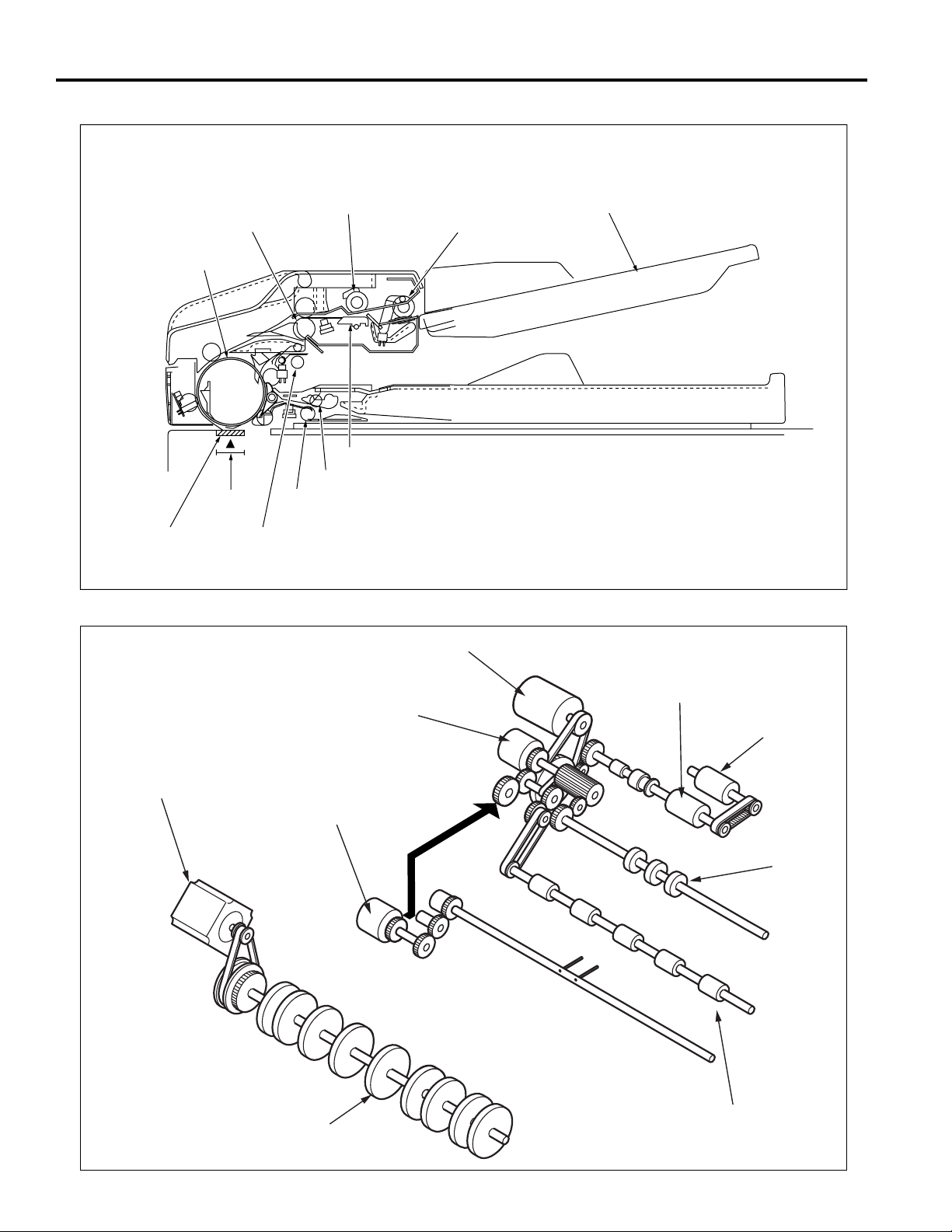
CENTER CROSS-SECTIONAL VIEW
Registration roller
Conveyance roller
Original
image read
Slit glass
position
Separation roller
Double feed prevention pad
Pressure pulley
Reversal roller
Paper exit roller
Paper feed roller
DRIVE SYSTEM DIAGRAM
Original feed motor
(M302)
Paper feed tray
Original conveyance
motor (M301)
Separation roller
Original feed CL (CL302)
Paper feed roller
Original pick-up CL (CL301)
Registration roller
Paper exit roller
Conveyance roller
2
Page 11
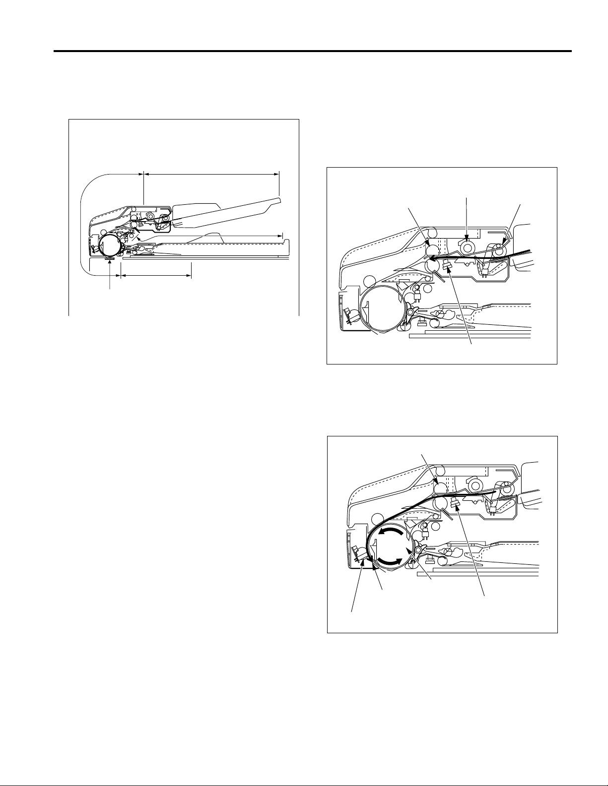
ORIGINAL CONVEYANCE PROCESS
As the figure below shows, the DF-315 is composed of the
paper feed section, conveyance section, reversal section,
and paper exit section.
Conveyance
section
Paper feed section
Single Side Original Copy Mode
(single side to single side copy, single side to double
side copy)
The originals set in the paper feed tray are fed by means
of the paper feed roller and separation roller to the
position where original registration PS (PS306) goes on.
DF-315
Paper exit section
Reversal section
Slit glass
(Read section)
The originals, which have been placed in the paper feed
tray with the front side facing up, are fed starting with the
topmost original. Originals that are fed are not conveyed
to the original glass. Reading is carried out as the original
passes by the slit glass section set midway through the
conveyance path.
The operational modes of the DF-315 include three
modes: (a) single side original copy mode, (b) double side
original copy mode, (c) mixed original copy mode. The
conveyance path is different for each mode.
Separation roller
Registration roller
Original registration PS
Paper feed roller
When original registration PS goes on, pre-feed is carried
out by the registration roller and the original is conveyed to
the conveyance roller. The conveyance roller conveys the
original to the position where original feed detect PS (PS308)
goes on. The original stops at the scanning standby position.
Registration roller
Original feed detect PS
3
Conveyancec roller
Scanning standby
position
Original registration PS
Page 12
DF-315
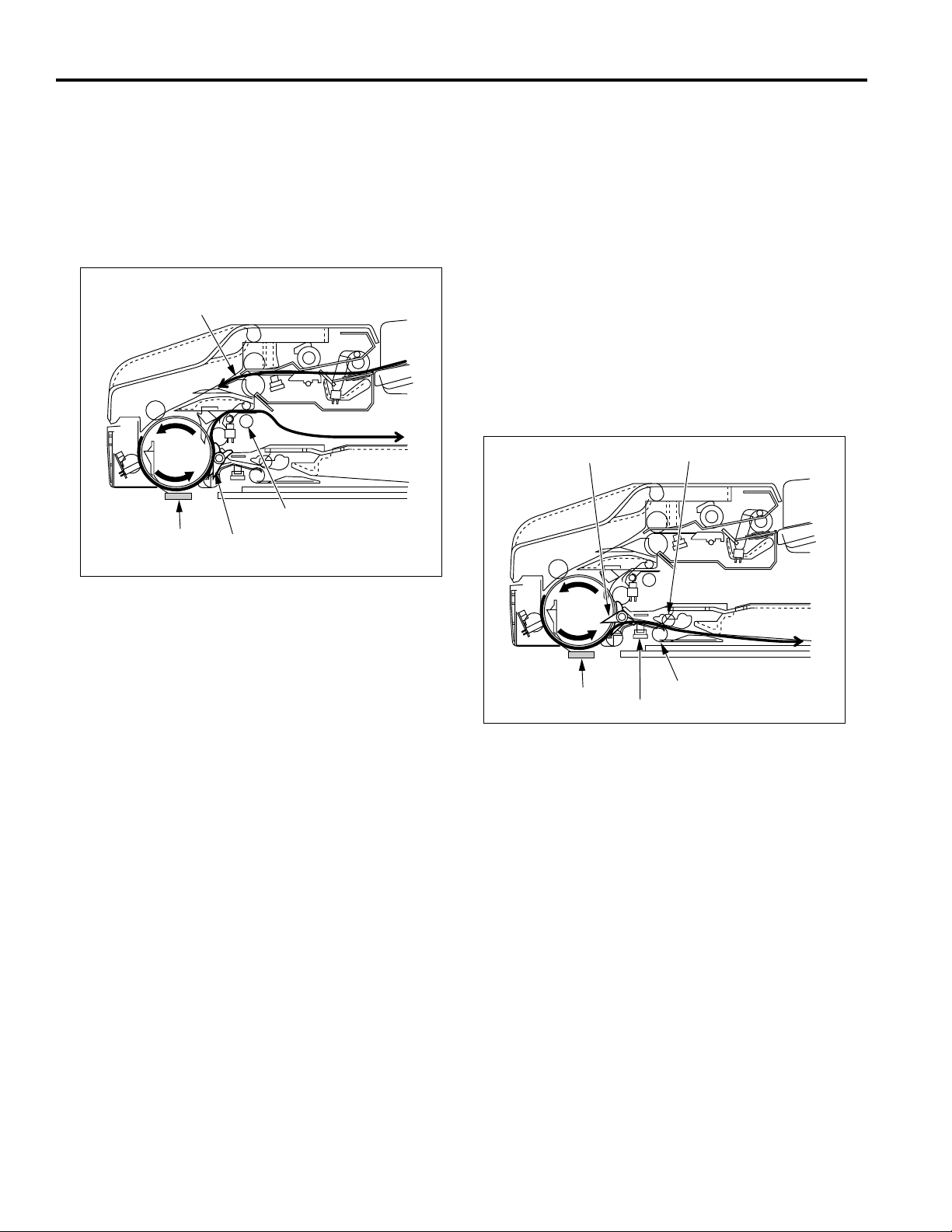
When scan is started, the conveyance roller rotates again
in the forward direction to convey the original. If there is
another original at this time, pre-feed is carried out.
Reading of the original is carried out when the original
passes over the slit glass. Originals which have been
read are conveyed around the circumference of the
conveyance roller by closing of the flapper and are ejected
to the paper exit section via the paper exit roller.
Next original
Paper exit roller
Slit glass
Flapper
Double Side Original Copy Mode
(double side to single side copy, double side to double
side copy)
The conveyance operation from feeding of the double
sided original to the front side scanning standby position is
the same as that for the single side original copy mode.
When scanning starts and reading of the front side is
completed, the original is conveyed to the reversal section
when the flapper opens and the paper exit path is blocked.
When original reverse detect PS (PS309) detects the
leading edge of the original that has been conveyed to the
reversal section and goes ON, pressure is applied to the
pressure pulley. As a result, the reversal roller and
pressure pulley clasp the original on both sides and
convey it to the inside of the reversal section.
Flapper
Pressure pulley
Slit glass
Reversal roller
Original reverse detect PS
4
Page 13

DF-315
When original reverse detect PS (PS309) detects the trailing
edge of the original and goes OFF, the reversal roller rotates in
the reverse direction to feed the original from the reversal
section to the conveyance roller. Since the original passes
over the top of the flapper at this time, the front and back sides
are reversed and the original is sent to the conveyance roller.
The conveyance roller conveys the original to the
scanning standby position.
Flapper Pressure pulley
Scanning
standby position
Original reverse detect PS
Reversal roller
When original reverse detect PS detects the trailing edge of
the original and goes OFF, the reversal roller rotates in the
reverse direction to feed the original from the reversal
section to the conveyance roller. Since the flapper is
closed at this time, the original is conveyed along the
flapper and is ejected to the paper exit section via the
paper exit roller.
Next original
Flapper
Original reverse detect PS
Paper exit roller
Reversal roller
When scanning of the back side starts, the flapper is
opened. As a result, the original which has been read is
conveyed to the inside of the reversal section again.
Flapper
Mixed Original/Z-Fold Original Mode
In the mixed original mode (can handle both same series
and different series of originals) and the Z-fold original
mode, the original size in the sub-scanning direction is
determined by to the ON time of original registration PS
(PS306), hence size detection takes place before the
scanning operation. This operation takes place for all
originals in the mixed original mode, and only for the first
original in the Z-fold original mode.
After size detection is completed, the original stops at the
scanning standby position. The subsequent operations
are the same for all copy modes. For details of the size
detection process, refer to [5] "Original Size Detection
Control" in "PAPER FEED/PAPER EXIT SECTION".
5
Page 14
DF-315
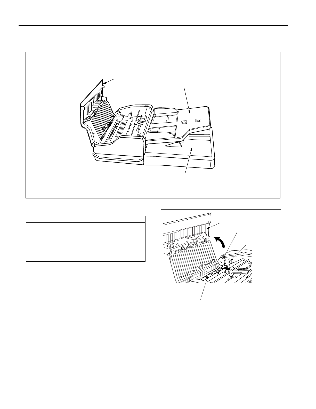
EXTERNAL SECTION
Composition
Open/close cover
Paper feed tray
Mechanisms
Mechanisms
Jam clearance
1*: Jam clearance
If a paper jam occurs during the feed process, open
the open/close cover, raise the conveyance guide
open/close lever, and rotate the release knob to
remove the jammed original.
Open/close cover *1
Release knob
Conveyance guide open/close
lever
Pressure release lever
Platen guide
Methods
Paper exit section
Open/close cover
Release knob
Conveyance
guide open/close
lever
Conveyance guide
6
Page 15
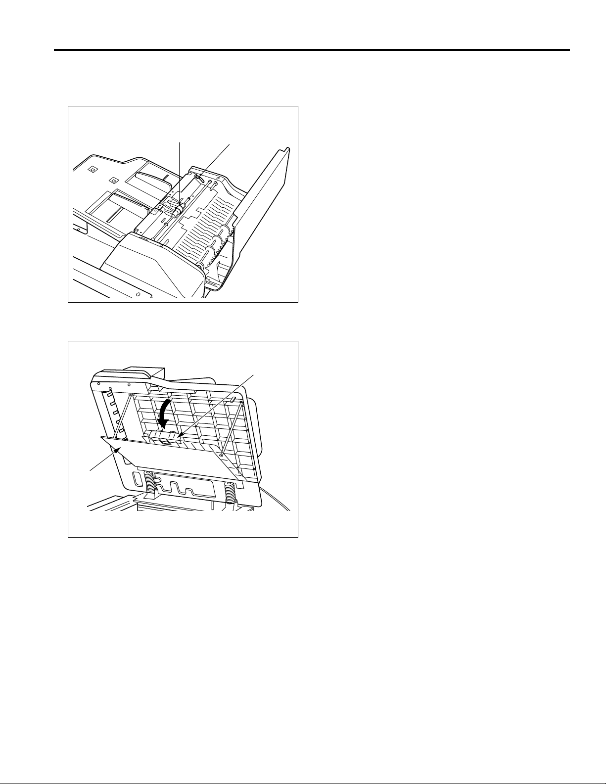
If the jammed original is hard to remove, operate the
pressure release lever to remove the pressure of the
separation roller, and then remove the original.
DF-315
Separation roller
Pressure release lever
If a paper jam occurs during the reversal process, the
jammed sheet can be removed by opening the platen guide.
Lock
Platen
guide
7
Page 16
DF-315
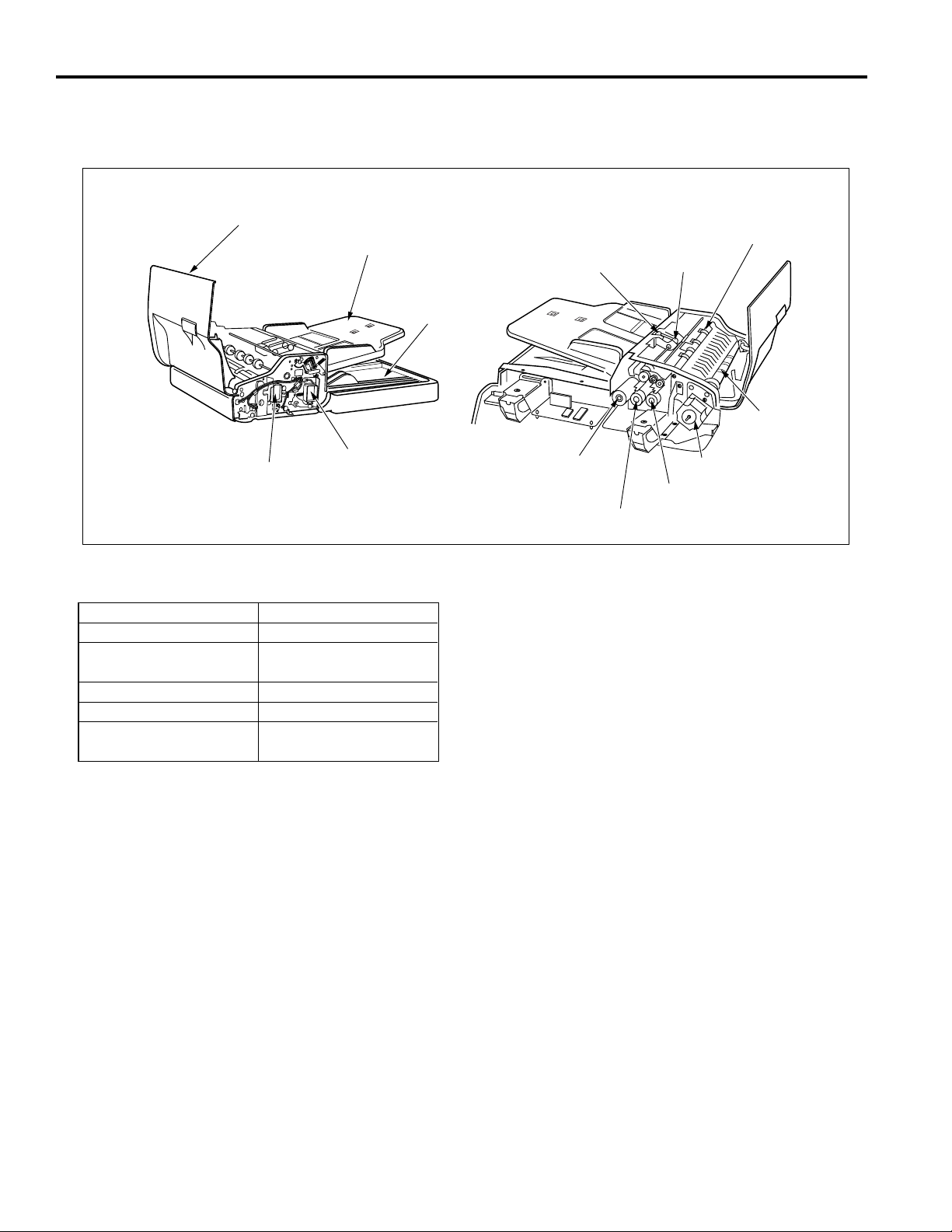
PAPER FEED/PAPER EXIT SECTION
Composition
Flapper SD
Mechanism
Mechanisms
Paper feed
Double feed prevention
Conveyance
Conveyance path switching
Reversal feed *2
Open/close cover
Paper feed tray
Original press SD
Methods
Paper feed roller
Double feed prevention pad
Separation roller
Conveyance roller
*1
Flapper
Reversal roller pressure
Reversal roller turn-back
Paper exit tray
Paper feed roller
Original feed motor
Original feed CL
Registration roller
Separation roller
Conveyance roller
Original conveyance motor
Original pick-up CL
8
Page 17
DF-315
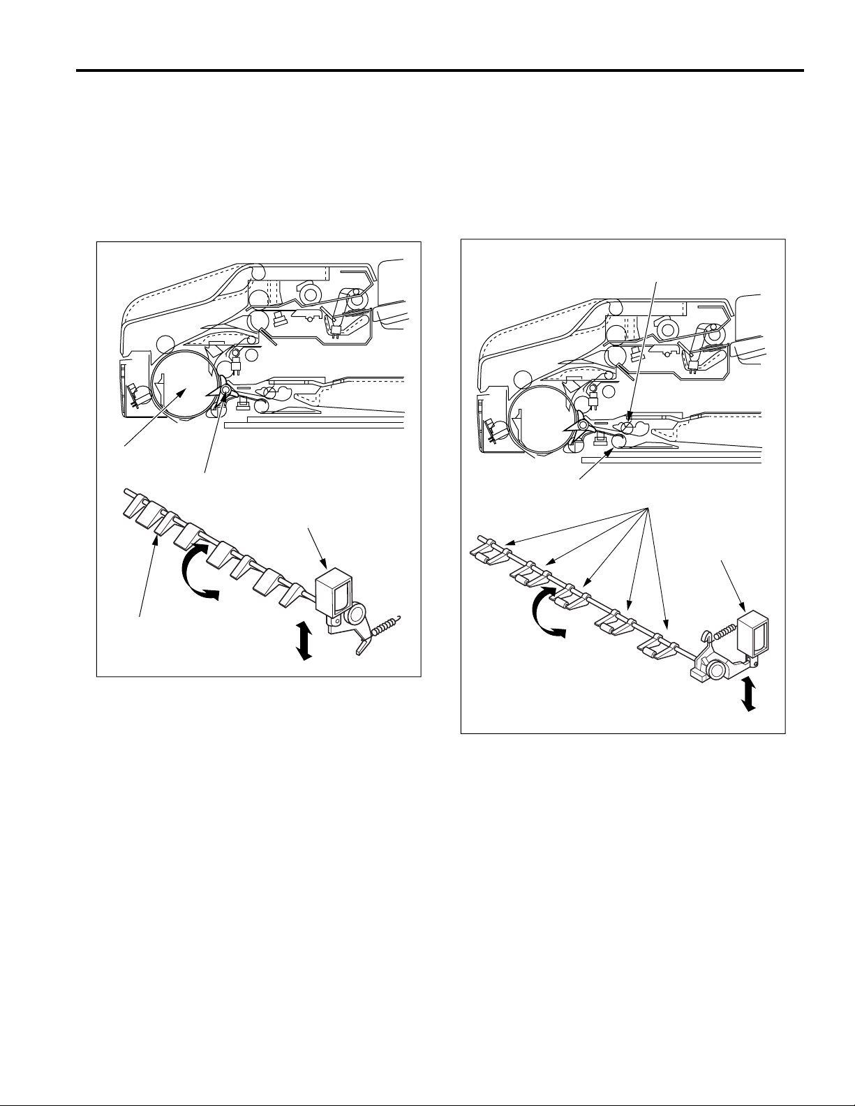
*1: Conveyance path switching
In the double side original copying, the conveyance
path after the end of reading operations differs for
front side copies and back side copies. Change of
the conveyance path is carried out by the flapper.
Turning flapper SD (SD301) ON and OFF switches
between the reversal section and the paper exit
section.
Conveyance roller
Flapper
Flapper SD
*2: Reversal feed
During double side original copy operation, the
original conveyed to the reversal section is held in
the standby mode on the reversal roller. Reversal
feed is activated by bringing the pressure pulleys into
contact with the reversal roller. Pressure of the
pressure pulleys is conducted by original press SD
(SD302).
Pressure pulley
Reversal roller
Pressure pulleys
Flapper
Original press SD
9
Page 18
DF-315
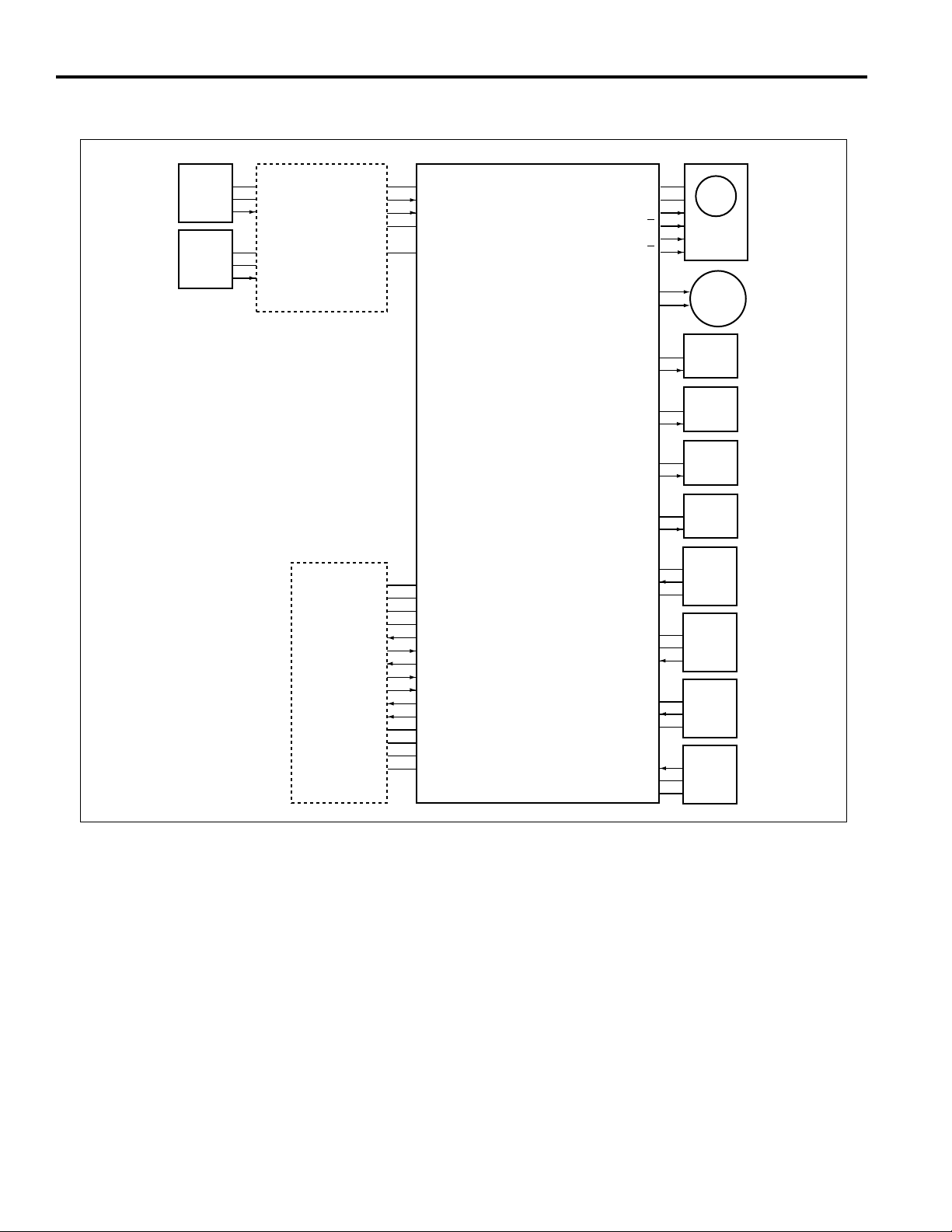
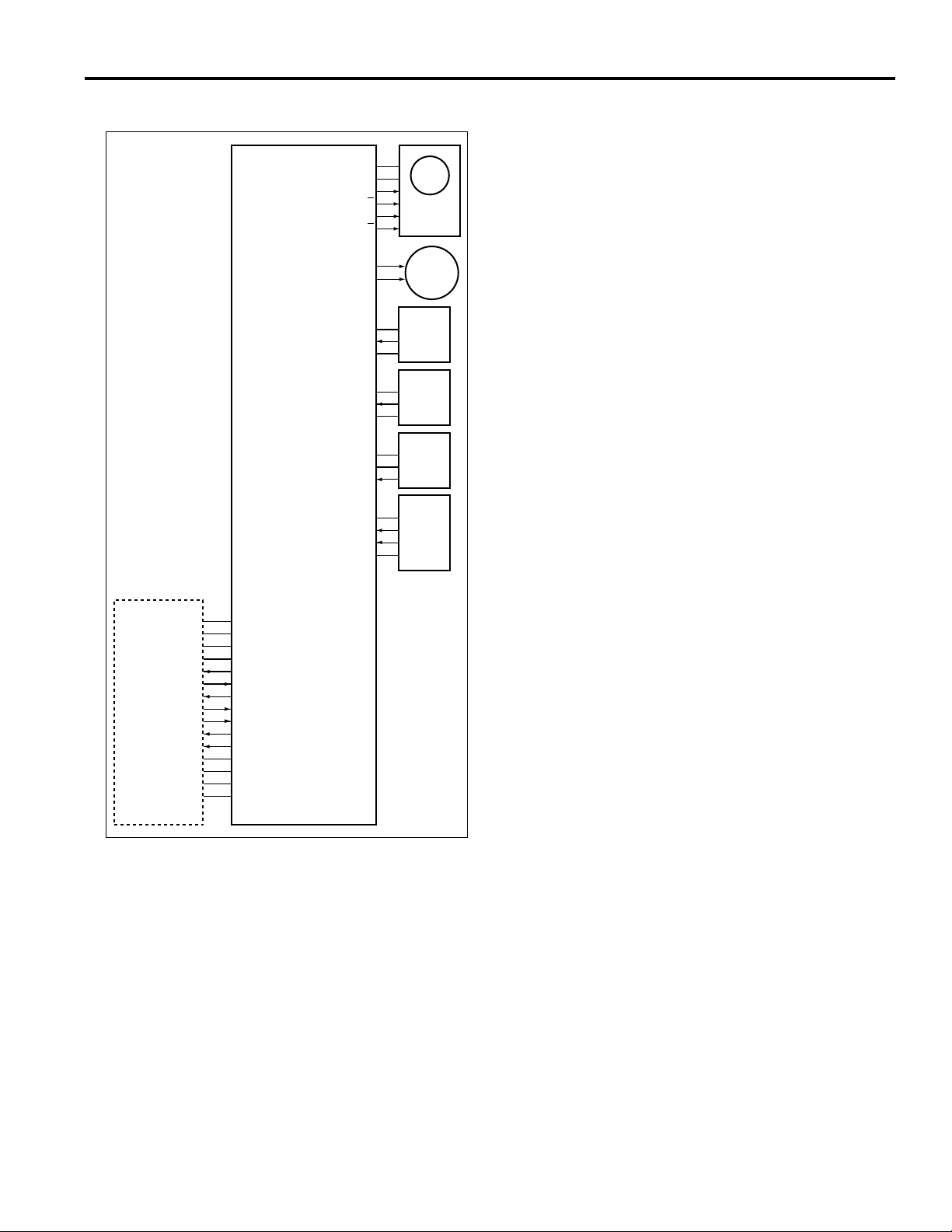
Paper Feed/Conveyance/Scan Control
PS302
PS303
5VDC
SGND
PS302
5VDC
SGND
PS303
PTBD
24VDC
PGND
PGND
SGND
DF RXD
DSR
5VDC
PGND
24VDC
24VDC
MAIN BODY
RTS
5VDC
PS303
PS302
SGND
VR301
DF TXD
CTS
DTR
VALID
DFCB
24VDC
24VDC
M301 DRIVE A
M301 DRIVE A
M301 DRIVE B
M301 DRIVE B
M302 DRIVE 1
M302 DRIVE 2
24VDC
CL301 DRIVE
24VDC
CL302 DRIVE
24VDC
SD301 DRIVE
24VDC
SD302 DRIVE
5VDC
PS304
SGND
5VDC
SGND
PS306
5VDC
PS309
SGND
PS305
SGND
5VDC
M301
M302
CL301
CL302
SD301
SD302
PS304
PS307
PS309
PS305
Paper feed takes place by transmitting the drive force of
motor M302 (original feed) to the paper feed roller and
separation roller. Conveyance takes place by transmitting
the drive force of motor M301 (original conveyance) to the
conveyance roller.
M301 and M302 are controlled by the DFCB (RADF control
board).
1. Operation
a. Sensor adjustment when the power is ON.
When SW2 (sub power) is ON, a sensitivity PS306
(original registration) and PS308 (original feed detect)
is adjusted automatically. However, if the RADF open/
close cover is open or an original is inside of the
RADF, there will be no automatic adjustment.
b. Original pressure operation
When a control signal from the main body is
received, CL301 (original pick-up) goes ON, and
after the specified time M302 starts to rotate in the
forward direction. This causes the paper feed roller to
be lowered, applying pressure to the original.
After the specified time, M302 and CL301 go OFF,
but the pressure on the original is maintained.
10
Page 19

DF-315
c. Paper feed operation
When CL302 (original feed) goes ON, the driving
force of M302 (original feed) is transmitted to the
paper feed roller and the separation roller.
CL302 goes ON at the same time as M302 performs
forward rotation. When M302 switches from forward
to reverse rotation, paper feed starts.
When PS306 (original registration) goes ON, the
reverse rotation of M302 is switched OFF after the
specified time.
d. Pre-feed of first sheet
When the reverse rotation of M302 stops, the motor
starts again to rotate in forward direction after the
specified time.
This causes the original to be moved to the
conveyance roller.
At the specified time after forward rotation of M302
has started, M301 (original conveyance) goes ON
and moves the original from the conveyance roller
to the scanning standby position.
When PS308 (original feed detect) detects the
leading edge of the original and turns ON, CL302 and
M302 go OFF. After the specified time, M301 slows
down and then goes OFF. At this point, the original
still moves a small distance further due to the inertia
of the conveyance roller and then stops. This is the
scanning standby position.
h. Original pressure release
When M301 completes the scanning operation for
the last original and goes OFF, CL301 and M302 go
ON which causes the original pressure to be
released. After the specified time, CL301 and M302
go OFF.
e. Pre-feed of second and further sheets
The forward rotation of M302 starts the pre-feed
process of the following original, but because the
motor immediately goes OFF, the original temporarily
stops before reaching the conveyance roller. When
M301 begins the scanning operation, the forward
rotation of M302 starts again. Pre-feed of the original
then is carried out while the preceding original is
being scanned.
f. Scanning operation (except last original)
At the specified time after M301 goes OFF, it goes
ON again and conveys the original over the slit glass
areaof the main body, where scanning is performed.
When PS306 detects the trailing edge of the original that
is being scanned and goes OFF, CL302 again goes ON
g. Scanning operation (last original)
During scanning, when M301 is ON and one of the
sensors PS302 (original size detect 1), PS303
(original size detect 2), or PS305 (no original detect)
goes OFF, the original currently being scanned is the
last one.
A sensor that is used to judge the last original differs
depending on the original size.
When PS307 (original exit detect) goes OFF, M301
also is switched OFF after the specified time.
11
Page 20

DF-315
2. Signals
a. Input signals
(1) PS302 (PS302 to PTDB to DFCB)
Original sub-scanning direction signal
[L]: Original is detected
[H]: Original is not detected
(2) PS303 (PS303 to PTDB to DFCB)
Original sub-scanning direction signal
[L]: Original is detected
[H]: Original is not detected
(3) PS304 (PS304 to DFCB)
M301 (original conveyance) encoder surface slit
detection signal
[L]: Slit is not detected
[H]: Slit is detected
(4) PS305 (PS305 to DFCB)
No original detection signal at the paper feed tray
[L]: Original is detected
[H]: Original is not detected
(5) PS306 (PS306 to DFCB)
Original detection signal at the conveyance roller en
trance section
[L]: Original is detected
[H]: Original is not detected
(6) PS307 (PS307 to DFCB)
Original detection signal at the paper exit section
[L]: Original is detected
[H]: Original is not detected
(7) PS308 A, B (PS308 to DFCB)
Original detection signal at the pre-scanning standby
position
[L]: Original is detected
[H]: Original is not detected
(8) DF RXD (MAIN BODY to DFCB)
Serial data line for transmitting operation status
informa tion from control board in main body to
RADF.
b. Output signals
(1) M301 DRIVE A, A, B, B (DFCB to M301)
M301 ON/OFF drive signal
24V
0V
(2) M302 DRIVE 1, 2 (DFCB to M302)
M302 (original conveyance) drive signal.
M302 rotation direction is controlled by switching the
current direction of these two signals.
State
Forward rotation
Reverse rotation
Stop
(3) CL301 DRIVE (DFCB to CL301)
CL301 (original pick-up) ON/OFF drive signal
[L]: CL301 ON
[H]: CL301 OFF
(4) CL302 DRIVE (DFCB to CL302)
CL302 (original feed) ON/OFF drive signal
[L]: CL302 ON
[H]: CL302 OFF
(5) DF TXD (DFCB to MAIN BODY)
Serial data line for transmitting operation status
informa- tion from RADF to main body CB (control
board).
(6) DTR (DFCB to MAIN BODY)
Send request from RADF to main body.
(7) CTS (DFCB to MAIN BODY)
Send enable from RADF to main body.
(8) VALID (DFCB to MAIN BODY)
Image forming start signal.
M302 DRIVE 1
H
L
L
M302 DRIVE 2
L
H
L
(9) DSR (MAIN BODY to DFCB)
Send enable from main body to RADF.
(10) RTS (MAIN BODY to DFCB)
Send request from main body to RADF.
12
Page 21
DF-315
Paper Exit/Reverse Conveyance Control
24VDC
24VDC
M301 DRIVE A
M301 DRIVE A
M301 DRIVE B
M301 DRIVE B
M302 DRIVE 1
M302 DRIVE 2
5VDC
PS304
SGND
SGND
PS306
5VDC
5VDC
SGND
PS307
5VDC
PS308 A
PS308 B
SGND
24VDC
PGND
PGND
SGND
DF RXD
5VDC
PGND
24VDC
24VDC
MAIN BODY
DSR
RTS
DF TXD
CTS
DTR
VALID
DFCB
Paper path switching in the exit area is carried out by
solenoid SD301 (flapper) which operates a flapper. In
duplex copy mode, the pressure pulley in the reversal
section is operated by the SD302 (original press).
SD301 and SD302 are controlled by the DFCB (RADF
control board).
M301
M302
PS304
PS306
PS307
PS308
1. Operation
a. Sensor adjustment when the power is ON.
When SW2 (sub power) is ON, a sensitivity of PS309
(original reverse detect) is adjusted automatically.
However, if the RADF open/close cover is open or an
original is in the inside of the RADF, there will be no
automatic adjustment.
b. Paper exit operation
In single-sided copy mode and when copying the
reverse side of a sheet in duplex copy mode, SD301
is OFF and the flapper is closed. The original is
therefore conveyed to the paper exit section after
scanning.
c. Reversal paper exit operation
When copying the first side of a sheet in duplex copy
mode, at the specified time after M301 (original
conveyance) goes ON and scanning starts, SD301
goes ON and the flapper opens. This causes the
original to be sent to the reversal section after
scanning.
At the same time as SD301 goes ON, M302 (original
feed) starts reverse rotation and the drive force is
transmitted to the reversal roller.
When PS309 detects the leading edge of the original
and goes ON, the SD302 goes ON after the specified
time and applies pressure to the pressure pulley. As
a result, the original which has been conveyed to the
reversal section is caught between the reversal roller
and pressure pulley, and conveyed to the inside of
the reversal section.
d. Reversal feed operation
When PS309 detects the trailing edge of the original
and goes OFF, both the M301 and M302 go OFF
after the specified time, and conveyance operation of
the original is stopped.
After a predetermined OFF interval, M302 starts
reverse rotation and feeds the original to the
conveyance roller side of the reversal section. At this
time, PS309 again goes ON and SD302 goes OFF
after the specified time. M302 goes OFF after the
specified time from PS309 goes OFF.
e. Pre-feed operation of next original when reading
back side of original
When PS309 goes OFF, M301 and M302 start
forward rotation after the specified time, and next
original pre-feed is carried out.
13
Page 22

DF-315
2. Signals
a. Input signal
(1) PS309 (PS309 to DFCB)
Original detection signal at the reversal section
[L]: Original is detected
[H]: Original is not detected
b. Output signals
(1) SD301 DRIVE (DFCB to CL301)
SD301 (flapper) ON/OFF drive signal
[L]: SD301 ON
[H]: SD301 OFF
(2) SD302 DRIVE (DFCB to SD302)
SD302 (original pressure) drive signal
[L]: SD301 ON
[H]: SD302 OFF
14
Page 23

DF-315
Original Size Detection Control
5VDC
SGND
PS302
5VDC
SGND
PS303
5VDC
VR301
SGND
PTDB
PS303
PS302
VR-301
5VDC
24VDC
PGND
PGND
SGND
DF RXD
5VDC
PGND
24VDC
24VDC
MAIN BODY
DSR
RTS
DF TXD
CTS
DTR
DFCB
SGND
PS302
PS303
VR301
1. Operation
a. Normal copy mode
The DFCB detects the original size from the
combination of the following signals.
(1) Detection of size in the main scanning direction
The guide plate is connected to VR301. The
resistance of VR301 varies according to the position
of the guide plate, enabling the size of the original in
the main scanning direction to be detected.
(2) Detection of size in the sub-scanning direction
The size of the original in the sub-scanning direction
is detected according to the combination of the ON/
OFF status of PS302 and PS303.
b. Original size detection in the mixed original/Z-
fold original mode
(1) Detection of size in the main scanning direction
The size of the largest original of mixed size originals
in the main scanning direction is detected according
to the position of the guide plate.
(2) Detection of size in the sub-scanning direction
The size of the original in the sub-scanning direction
is detected according to the time at which PS306
(original registration) goes ON after the original is fed
from the registration roller.
(3) Size detection process in the sub-scanning direction
When original pre-feed is started by the registration
roller, M301 (original conveyance) rotates in the
forward direction after the specified time from when
PS306 goes ON, causing the original to be conveyed
to the paper exit section. M301 continues to rotate in
the forward direction until PS306 detects the trailing
edge of the original and goes OFF. The size of the
original in the sub-scanning direction is detected
according to the ON time of PS306.
The size of the original placed in the paper feed tray is
detected by PS302 (original size detect 1), PS303
(original size detect 2), and VR301 (original size detect).
PS302, PS303, and VR301 are controlled by the DFCB
(RADF control board) via the PTBD (Paper tray board).
Inside the DFCB is a non-volatile memory for recording
the timing data and original size detection threshold
values.
15
Registration roller
PS308
(Original feed detect)
PS306
(Original registration)
Conveyance roller
Page 24

DF-315
M301 (original conveyance) rotates in the reversal
direction after the specified time from PS306 (original
registration) goes OFF and returns the leading edge
of the original that has been conveyed to the paper
exit section to the scanning standby position. The
trailing edge of the original which has been returned
is conveyed to the exit section due to the
configuration of the conveyance section. The
reversal rotation of the M301 stops after the specified
time from PS308 (original feed detect) detects the
leading edge of the original and goes ON.
Scanning standby
position
(4) The original size detection operation with the second
original and subsequent originals has a different start
timing for the single side mode and double side mode.
Single side mode: At time of starting scanning opera-
tion of former original.
Double side mode:At time of starting scanning opera-
tion of former original back side.
2nd original
1st original
PS308
(Original feed detect)
Conveyance roller
Following this, there is the same reading as in the
normal mode (scanning operation).
The process of detecting the size of the original in the
sub-scanning direction takes place only for in the all
originals in the mixed original mode, and for the first
original in the Z-fold original mode.
c. List of the possible mixing of sizes.
(
: Same size : Same series : Different series
¥ : Mixing not possible – : Setting not possible.)
(1) AB series
Standard original (maximum original size that is detected with the guide plate).
A3 A4 B4 B5 A4R A5R B5R A5
A3
A4
B4
B5
A4R
A5
Other originals
B5R
A5R
✕✕✕
–––––
✕✕✕✕
✕
–
–
–
–
–
–
–
(2) Inch series
Standard original (maximum original size that is detected with the guide plate).
11✕17 8.5✕11 8.5✕14 8.5✕11R 8.5✕5.5 8.5✕5.5R
–
11✕17
✕
11
8.5
✕
14
8.5
8.5
✕
11R
✕
5.5
8.5
Other originals
8.5
✕
5.5R
✕✕✕✕✕
–
–
–
2. Signals
a. Input signal
(1) VR301 (VR301 to PTBD to DFCB)
Original main scanning direction signal
–
–
–
–
–
–
–
–
–
–
–
–
–
–
–
–
–
–
–
–
16
Page 25

DISASSEMBLY AND REASSEMBLY
DF-315
Caution: Be sure that the power cord has
been unplugged from the power
outlet.
Removing and Reinstalling the Paper
Dust Removing Pad
a. Procedure
(1) Open the open/close cover.
(2) Remove the set screw, then remove the paper dust
removing pad.
Paper dust removing pad
Set screw
Removing the RADF
a. Procedure
(1) Remove the rear cover from the main body.
(2) Remove the two connectors (CN100, CN102).
(3) Remove the set screw, then withdraw the cable from
the main body.
Cable
Set screw
Connector
(CN102)
Connector
(CN100)
(3) Reinstall the paper dust removing pad in the opposite
sequence to removal.
17
Page 26

DF-315
(4) Remove the set screw from each, then remove the two
stoppers.
(5) Remove the two set screws from each, then remove the
two fixing plates/R.
Set screw
Stopper
Fixing
plate/R
Set
screws
(6) Open the RADF.
(7) Remove the set screw from each while supporting the
RADF, then remove the two fixing plates/F.
(8) Remove the RADF from the main body.
Fixing plate/F
Set
screw
18
Caution: Be sure to support the RADF during
this process as it may fall to the rear
side when the fixing plate/F has been
removed.
Page 27

DF-315
Reinstalling the RADF
a. Procedure
(1) Remove the two set screws, then remove the original
stopper plate of the main body.
Set screw
Original stopper plate
Set screw
(2) Install the two RADF positioning jigs in the hole of the
original stopper plate.
(3) After installing the RADF, temporarily fix the two fixing
plates /F using one set screw each.
“Caution: Set each fixing plate/F with the long
hole over the guide screw.
(4) Close the RADF, and match the reference hole with the
RADF positioning jig.
Guide screw
Set screw
Reference
hole
(round hole)
Reference
hole
(long hole)
Fixing plate/F
RADF
positioning jigs
19
Page 28

DF-315
(5) When the positions are matched, tighten the two set
screws of each fixing plate /R.
(6) Open the RADF, then tighten the set screw of each
fixing plate /F.
Set screws
Fixing plate/R
(9) Adjust the adjustment screws A and B alternately so
that both stoppers contact with the slit glass.
Caution: Repeat Step (8) to (9) until both stoppers
make contact with the slit glass
simultaneously.
Adjustment
screw B
Adjustment
screw A
(10) Reinstalling hereafter is performed in the opposite
sequence to removal.
(7) Remove the two RADF positioning jigs, then install the
original stopper plate.
(8) Close the RADF, and check whether or not the stoppers
of the read section at the two locations contact with the
slit glass.
Stopper
Projection
Slit glass
Stopper
Projection
20
Page 29

DF-315
Removing and Reinstalling the Paper
Feed Roller/Separation Roller
a. Procedure
(1) Remove the four set screws to remove the rear cover.
Set screws
Set screws
Rear cover
(2) Open the open/close cover.
(3) Rotate the gear until the two pressure pins on the pick-
up shaft point up.
Gear
(4) Remove the two springs.
(5) Remove the stop ring and slide the bearing to the side.
(6) Slide the paper feed roller assembly towards the front
side, then remove it.
Bearing
Front
Stop ring
Springs
Paper feed
roller assembly
(7) Remove the bearing.
(8) Remove the two stop rings, then remove the guide
lever.
Separation roller
Pick-up clutch
Stop rings
Bearing
Pressure
pin
Pick-up shaft
Caution: The pick-up shaft cannot be turned
directly. Be sure to rotate it via the gear.
Paper
feed
drive
belt
Paper feed
roller
Spring
Guide lever
Side shape of roller
(9) Remove the separation roller and paper feed roller.
Caution: When reinstalling the separation roller,
pay attention to correct roller orientation.
(The correct orientation can be
determined by looking at the side shape of
the roller.)
(10) Reinstall the paper feed roller and separation roller in
the opposite sequence to removal.
21
Page 30

DF-315
Removing and Reinstalling the Double
Feed Prevention Pad
a. Procedure
(1) Remove the paper feed roller assembly.
(2) Push the pressure release lever so that on the double
feed prevention pad is released.
Double feed
prevention pad
Pressure
release lever
(3) Push the double feed prevention pad down, slide it
towards the paper feed tray, and then remove it.
Double feed prevention pad
(4) Reinstall the double feed prevention pad in the oppo-
site sequence to removal.
Paper feed tray
22
Page 31

DF-315 ELECTRICAL PARTS LAYOUT DRAWING
DF-315
PS308
Original feed detect PS
PS301
DF open/close detect PS
SD301
Flapper SD
PS307
Original exit detect PS
PS309
Original reverse detect PS
SD302
Original press SD
PS306
Original registration PS
PS305
No original detect PS
PS303
Original size detect PS2
VR301
Original size detect VR
PTBD
Paper tray board
PS302
Original size detect PS1
PS304
M302
Original feed motor
DFCB
RADF control board
Motor clock detect PS
MS301
Cover open/close detect MS
CL302
Original feed CL
CL301
Original pick-up CL
M301
Original conveyance motor
23
Page 32

DF-315
DF-315 CONNECTOR LAYOUT DRAWING
46/47 (W:3 PIN)
10 (W:5 PIN)
51 (W:4 PIN)
33/38 (W:6 PIN)
49/50 (W:4 PIN)
45 (W:3 PIN)
52/53 (W:3 PIN)
55/56 (W:2 PIN)
28 (W:3 PIN)
44 (W:3 PIN)
46/47 (W:3 PIN)
12 (W:3 PIN)
11 (W:6 PIN)
43 (W:3 PIN)
57/58
(W:2 PIN)
40 (W:3 PIN)
41 (W:3 PIN)
54 (W:4 PIN)
31 (BK:7 PIN)
30 (BK:8 PIN)
34/35 (W:2 PIN)
36 (W:4 PIN)
37 (W:4 PIN)
1 (GY:10 PIN)
24
3 (W:10 PIN)
9 (W:7 PIN)
4 (W:4 PIN)
DFCB
10 (W:2 PIN)
5 (W:5 PIN)
6 (W:10 PIN)
7 (W:9 PIN)
2 (W:5 PIN)
8 (W:3 PIN)
11 (W:12 PIN)
Page 33

DF-315 TIMING CHART
8.5x11, 1-SIDED ORIGINALS, 5 SHEETS
DF-315
8.5x11, 2-SIDED ORIGINALS, 2 SHEETS
(sec)
(sec)
Start button ON
0 1 2 3 4 5 6 7 8 9 10 11 12
F
R
0 1 2 3 4 5 6 7 8 9 10 11 12
F
R
25
Page 34

DF-315
This page left blank intentionally.
26
Page 35

DF-315 OVERALL WIRING DIAGRAM
[How to see the diagram]
1.The signals shown reflect levels present
under normal idling conditions with
the main switch turned ON.
2.Wiring symbols in the figure are as follows.
(1) [Symbol]
50-1
V
V
DFCB
Faston
Wire(Violet)
(2)
Connector
Crimp
Signal typs are as follows :
Active high
H
Active low
L
Analog signal
*
Pulse signal
P
(3) RC is ribbon cable.
(4) Signal flow
The solid black circle ( ) among
the connector symbols ( )
indicates the direction of signal flow.
Example)
5VDC
PS1
Direction of
signal flow
PS1
CB
SGND
(5) [Colour code]
BN - Brown B - Blue
R - Red V - Violet
O - Orange GY - Gray
Y - Yellow W - White
GN - Green BK - Black
LB - Light blue P - Pink
Example: Y/GN represents
green yellow striped pattern.
CN30-1
CN30-4
CN30-5
CN30-8
CN31-4
CN31-1
CN31-6
CN31-2
CN31-3
CN31-5
CN31-7
CN30-7
CN30-6
CN30-3
CN30-2
MAIN BODY
27
Page 36

This page left blank intentionally.
28
Page 37

PARTS CATALOG
Model
DF-315
NOVEMBER 2000
KONICA BUSINESS TECHNOLOGIES, INC.
Page 38

Page 39

How to use this catalog
This parts catalog includes illustrations and part numbers for all replacement parts and assemblies used in this model.
Model-specific parts are identified in the illustrations with reference
numbers. Use the reference number to locate the corresponding part
number on the facing page.
Common hardware items, such as screws, nuts, washers, and pins,
are identified in the illustrations with reference letters. Use the reference
letter to locate the corresponding part number on the hardware listing in
the lower right hand corner of the facing page.
If you know a part number, but don’t know where the part is used, use
the numerical index to determine the page number and reference number for that part. Because some common parts are used in several
places, there may be more than one entry. Refer to the illustrations to
see where the part may be used.
If you know a part’s description, but don’t know where to look to find
the part number, use the alphabetical index to determine likely page and
reference numbers. Then look at the illustrations to determine that you
have identified the correct part. Locate the part number using the listing
on the opposite page.
Retail pricing that appears with the numerical index, while valid when
this catalog was printed, is subject to change without notice. The prices
are only suggested prices and are provided only for reference. Dealers
may determine their own selling prices. For up-to-date pricing, refer to
current Konica price lists or contact the Konica Parts Distribution Center.
How to order parts
Use standard Konica parts ordering procedures to obtain these parts.
For ordering options, contact Konica’s Parts Distribution Center.
When ordering parts, be sure to specify part numbers exactly as listed in
this catalog.
NOTE: Electrical parts may include previously used components.
Model DF-315 Konica Business Technologies, Inc. Page iii
1st Edition November, 2000
Page 40

This page left blank intentionally.
Page iv Konica Business Technologies, Inc. Model DF-315
November, 2000 1st Edition
Page 41

How to use this catalog . . . . . . . . . . . . . . . . . . . . . . . . . iii
Contents . . . . . . . . . . . . . . . . . . . . . . . . . . . . . 1
DF-315 . . . . . . . . . . . . . . . . . . . . . . . . . . . . . 2
Wiring . . . . . . . . . . . . . . . . . . . . . . . . . . . . 22
Alphabetical index . . . . . . . . . . . . . . . . . . . . . . . . . . . 25
Numerical index, Retail price list . . . . . . . . . . . . . . . . . . . . 27
Contents
Model DF-315 Konica Business Technologies, Inc. Page 1
1st Edition November, 2000
Page 42

DF-315
Page 2 Konica Business Technologies., Inc. Model DF-315
November, 2000 1st Edition
Page 43

REF. PART NUMBER DESCRIPTION
NO.
1 120A10450 Ground leaf spring
2 129H10351 Stopper
3 120A12051 Rear cover
4 120A12040 Sub cover
5 129H-1140 Hinge L ass’y
6 129H10220 Fixed plate R
7 129H10052 Leaf spring
8 120A10151 Base plate
9 13LK-9010 Control board
10 120AP0010 Locking card spacer
11 120A12063 Front cover
12 120A12013 Base cover
13 120A14041 Stopper arm
14 129H-1411 Pressure plate ass’y
15 120A10132 RF plate
16 129H-1180 Hinge R ass’y
17 120AP0008 Locking wire saddle
18 129H10580 Adjusting screw
19 129H14011 Pressure plate
20 129H10210 Hinge screw
21 120A12070 Screw
22 120A14060 Belt holder
23 120A14050 Belt mylar
24 120A14010 Stopper belt
25 13LK14020 Sponge sheet
26 12TK10330 Screw
27 120AP0003 Snap band
28 120AP0006 Screw
29 120AP0005 Card spacer
HARDWARE
REF.
LTR.
a 00Z163041
b 00Z184082
c 00Z184063
d 00Z254101
e 00Z164083
f 00Z193043
PART
NUMBER
Model DF-315 Konica Business Technologies., Inc. Page 3
1st Edition November, 2000
Page 44

DF-315
Page 4 Konica Business Technologies., Inc. Model DF-315
November, 2000 1st Edition
Page 45

REF. PART NUMBER DESCRIPTION
NO.
1 120A12030 Open-close cover knob
2 120A12020 Open-close cover knob
3 120A10190 Guide plate spring
4 120A45060 Roller
5 120A45610 Roller shaft
6 120A45600 Open-close roller plate spring
7 120A10170 Open-close cover lever
8 120A10180 Open-close cover spring
9 120A45570 Spring
10 120A45170 Reflect plate
11 120A10160 Open-close cover shaft
12 120A45590 Roller
13 129H45590 Resist roller
14 120A45240 Roller
15 120A-1210 Fulcrum plate ass’y
16 120A77051 Gear
17 120A10081 Side plate F ass’y
18 120A10230 Roller bracket
19 129H-4720 Cleaner ass’y
20 120A45700 Shaft holder
21 120A45690 Bushing
22 120A45970 Open-close roller plate spring
23 120A97041 Operation label
HARDWARE
REF.
LTR.
a 00Z253081
b 00Z670306
c 00Z670506
d 00Z283061
e 00Z183063
PART
NUMBER
Model DF-315 Konica Business Technologies., Inc. Page 5
1st Edition November, 2000
Page 46

DF-315
Page 6 Konica Business Technologies., Inc. Model DF-315
November, 2000 1st Edition
Page 47

REF. PART NUMBER DESCRIPTION
NO.
1 120A97010 Knob seal
2 120A45515 Guide
3 120A45531 Exit roller plate spring
4 120A45520 Paper exit roller
5 120A45542 Guide plate (B)
6 120A45560 Spring
7 120A73030 Actuator spring
8 120A73020 Actuator
9 120A85520 Photosensor
10 120A73010 Sensor holder
11 120A45100 Roller plate spring
12 120A73040 Harness plate
13 120A10071 Upper guide
14 120A45080 EX roller shaft
15 120A45090 Roller
16 120A45070 Roller
17 120A77030 Gear (Z=26)
18 120A45680 Bushing
19 120A45552 Guide
20 120A90020 EXITS wiring
21 120A45980 Guide holder
22 120A-4692 Guide ass’y
23 120AP0003 Snap band
24 120A10530 Pad
25 120A45940 Screw
HARDWARE
REF.
LTR.
a 00Z253081
b 00Z283063
c 00Z670506
d 00Z742106
e 00Z183063
f 00Z283061
g 00Z670406
PART
NUMBER
Model DF-315 Konica Business Technologies., Inc. Page 7
1st Edition November, 2000
Page 48

DF-315
Page 8 Konica Business Technologies., Inc. Model DF-315
November, 2000 1st Edition
Page 49

REF. PART NUMBER DESCRIPTION
NO.
1 13LK80010 Motor ass’y
2 120A45200 Gear
3 120A15080 Paper reverse tension spring
4 120A45190 Shaft
5 120A77030 Gear (Z=26)
6 120A77020 Gear (Z=50)
7 120A15060 Motor tension plate
8 120A15070 Motor mounting plate
9 120A15020 Belt (L=200)
10 120A76520 Pulley (Z=50,58)
11 120A75010 Bearing
12 120A77010 Gear (Z=20)
13 120A77040 Gear (Z=50,20)
14 120A10020 Adjusting plate rear
15 120A10010 Spacer R
16 120A10060 L stay
17 120A73050 Bracket sensor
18 129H85540 Read sensor
19 120A-4520 Roller plate spring ass’y
20 120A77060 Gear (Z=23)
21 129H76510 Pulley/A (Z=30/28)
22 120A45680 Bushing
23 120AP0008 Locking wire saddle
24 120AP0007 Edging saddle
25 120A45180 Read roller
26 120A10090 Spacer F
27 120A10050 R guide
28 120A-1061 R guide ass’y
29 120AP0002 Mini clamp
30 120AP0003 Snap band
31 129H90131 Wiring /F
32 120A90060 RDS wiring
HARDWARE
REF.
LTR.
PART
NUMBER
a 00Z670506
b 00Z742106
c 00Z713166
d 00Z670706
e 00Z194063
f 00Z284061
g 00Z183063
h 00Z921332
j 00Z283081
Model DF-315 Konica Business Technologies., Inc. Page 9
1st Edition November, 2000
Page 50

DF-315
Page 10 Konica Business Technologies., Inc. Model DF-315
November, 2000 1st Edition
Page 51

REF. PART NUMBER DESCRIPTION
NO.
1 120A45130 Front guide
2 120A45120 Rear guide
3 120A45141 Upper shaft spacer
4 120A45110 Upper shaft
5 120A45170 Reflect plate
6 120A45161 Lower guide
7 120A46000 Lower holder
8 120A46010 Mylar
9 120A45990 Upper holder
10 12TK10330 Screw
11 120A45041 Guide
12 120A45060 Roller
13 120A45050 Roller shaft
14 120A-4750 Solenoid ass’y
15 120A73161 Solenoid mounting plate
16 120A44050 Lever
17 120A44080 Lever spring
18 120A90010 SBS wiring
19 120A45660 Screw
20 120A45670 Shaft holder
21 120A10040 Plate
22 120A10030 Base plate
23 120A45640 Guide spring
24 120A-4740 Read S holder ass’y
25 120A45021 Sensor mylar
26 129H85510 Sensor/A
27 120A45621 Platen guide
28 120A45650 Spacer
29 120A45011 Roller plate spring
30 120A45630 Platen guide plate (R)
31 120A-4730 Platen guide plate ass’y
32 120AP0007 Edging saddle
HARDWARE
REF.
LTR.
a 00Z163051
b 00Z670406
c 00Z183053
d 00Z284061
e 00Z283063
f 00Z670506
g 00Z670306
h 00Z163121
j 00Z183063
k 00Z284063
PART
NUMBER
Model DF-315 Konica Business Technologies., Inc. Page 11
1st Edition November, 2000
Page 52

DF-315
Page 12 Konica Business Technologies., Inc. Model DF-315
November, 2000 1st Edition
Page 53

REF. PART NUMBER DESCRIPTION
NO.
1 120A45150 Pressure roller fulcrum shaft
2 120A44020 Roller
3 120A44030 Pressure roller spring
4 120A44010 Roller arm
5 120A44090 Screw
6 120A44060 Separate arm
7 120A44070 Separator spring
8 120A-4430 Pressure solenoid ass’y
9 120A73150 Pressure solenoid bracket
10 120A45030 Roller
11 129H15040 Belt /A
12 120A45690 Bushing
13 120A45700 Shaft holder
14 12TK76580 Pulley/B (Z=20)
15 120A90040 Solenoid wiring
16 120AP0003 Snap band
HARDWARE
REF.
LTR.
a 00Z163051
b 00Z670706
c 00Z670506
d 00Z194043
e 00Z743146
f 00Z743126
PART
NUMBER
Model DF-315 Konica Business Technologies., Inc. Page 13
1st Edition November, 2000
Page 54

DF-315
Page 14 Konica Business Technologies., Inc. Model DF-315
November, 2000 1st Edition
Page 55

REF. PART NUMBER DESCRIPTION
NO.
1 120A76560 Pulley
2 120A15050 Timing belt (L=124)
3 120A45441 Pick-up holder
4 120A45470 Pick-up spring
5 120A45820 Conveyance roller
6 120A45720 Clip
7 129H45060 Pick spring
8 120A45791 Mylar
9 12TK15290 Clip
10 120A15110 Joint
11 120A45380 Lever
12 120A45370 Lever spring
13 120A45430 Pick-up roller shaft
14 120A-4611 Lever bracket ass’y
15 129H-4740 Pick-up clutch ass’y
16 129H77010 Gear
17 120A45680 Bushing
18 120A10123 Upper guide
19 120A10111 Lower guide
20 120A45330 Lower guide mylar (A)
21 129H45021 Foam pad (front) 1
22 120A45350 Sponge sheet (F)
23 120A45340 Sponge sheet (L)
24 120A97060 Knob label
25 12TK10330 Screw
26 129H45041 Pick-up holder R
27 129H45050 Cushion
HARDWARE
REF.
LTR.
a 00Z670506
b 00Z742086
c 00Z670206
d 00Z922410
e 00Z283061
f 00Z193053
g 00Z610611
PART
NUMBER
Model DF-315 Konica Business Technologies., Inc. Page 15
1st Edition November, 2000
Page 56

DF-315
Page 16 Konica Business Technologies., Inc. Model DF-315
November, 2000 1st Edition
Page 57

REF. PART NUMBER DESCRIPTION
NO.
1 120A45680 Bushing
2 120A-4580 Separator pad ass’y
3 120A45211 Fanning spring holder
4 120A45220 Fanning spring
5 120A45290 Stopper
6 120A85530 Sensor ass’y
7 120A45021 Sensor mylar
8 129H85510 Sensor/A
9 129H45010 Paper exit neutralizing brush
10 120A45250 Shaft
11 120A85520 Photosensor
12 120A10100 Separation base
13 120A45260 Fanning plate spring
14 120A-7380 Sensor bracket ass’y
15 120A73190 Sensor spring
16 120A73200 Sensor lever
17 120A45500 Pick cam
18 120A45310 Shutter level
19 120A45300 Auxiliary stopper
20 120A45271 Fanning lever holder
21 120A45320 Shutter spring
22 120A45280 Fanning lock plate spring
23 120A-4671 Shaft ass’y
24 120A45720 Clip
25 129H90091 Wiring /C
26 120A90030 Sensor wiring
27 120AP0013 Screw
28 120AP0002 Mini clamp
29 120AP0003 Snap band
30 12TK73080 Mylar
31 120A45960 Pick support spring
HARDWARE
REF.
LTR.
PART
NUMBER
a 00Z670506
b 00Z284061
c 00Z670306
d 00Z193061
e 00Z163041
f 00Z670406
g 00Z163121
Model DF-315 Konica Business Technologies., Inc. Page 17
1st Edition November, 2000
Page 58

DF-315
Page 18 Konica Business Technologies., Inc. Model DF-315
November, 2000 1st Edition
Page 59

REF. PART NUMBER DESCRIPTION
NO.
1 120A10240 Plate spring
2 120A73120 Bracket
3 129H85011 Microswitch
4 120A77060 Gear (Z=23)
5 120A45390 Latch lever
6 120A44080 Lever spring
7 120A77070 Gear (Z=25)
8 120A73061 Mounting plate
9 120A45400 Pick connecting shaft
10 120A82010 Clutch
11 120A45720 Clip
12 120A45410 Separator connect shaft
13 120A77030 Gear (Z=26)
14 120A15090 Drive connecting shaft
15 120A82020 Clutch
16 129H80020 Motor
17 120AP0002 Mini clamp
18 120A77010 Gear (Z=20)
19 120A77080 Gear (Z=18)
20 129H76520 Pulley/C (Z=30/20)
21 120A15040 Belt (L=124)
22 129H76531 Pulley/D (Z=20)
23 120A76540 Pulley
24 120A15030 Belt (L=166)
25 120A85550 Photosensor
26 120A73070 Sensor mounting plate
27 120A45680 Bushing
28 120A90070 Clutch wiring
29 120AP0008 Locking wire saddle
30 12TK10330 Screw
HARDWARE
REF.
LTR.
PART
NUMBER
a 00Z283061
b 00Z163141
c 00Z670506
d 00Z712106
e 00Z193053
f 00Z473083
g 00Z742126
h 00Z712086
Model DF-315 Konica Business Technologies., Inc. Page 19
1st Edition November, 2000
Page 60

DF-315
Page 20 Konica Business Technologies., Inc. Model DF-315
November, 2000 1st Edition
Page 61

REF. PART NUMBER DESCRIPTION
NO.
1 120A40012 Tray guide F
2 120A40021 Tray guide R
3 13LK40010 Tray
4 120A40040 Tray rack
5 120A77090 Pinion gear (Z=52)
6 120A73110 Gear plate
7 129H40031 Tray window cover
8 120A90110 VR wiring
9 55WA85520 Photosensor
10 129H40041 Tray window cover 2
11 13LK88010 Tray board
12 120A-1190 Tray fulcrum ass’y
13 129H40022 Tray lower cover
14 129H40100 Tray spacer R
15 120A97030 Upper limit seal
16 13LK90100 Tray wiring
17 13LK90120 TR wiring
18 120A40090 Tray guide damper F
19 120A40100 Tray guide damper R
20 120A40070 Slide sheet
21 120A40110 Slide mylar
22 13GA46720 Tray sensor mylar
23 120B97021 Size indication label G
24 120AP0012 Snap ring
HARDWARE
REF.
LTR.
a 00Z253081
b 00Z194043
c 00Z922410
d 00Z253102
PART
NUMBER
Model DF-315 Konica Business Technologies., Inc. Page 21
1st Edition November, 2000
Page 62

Wiring
Page 22 Konica Business Technologies., Inc. Model DF-315
November, 2000 1st Edition
Page 63

REF. PART NUMBER DESCRIPTION
NO.
1 120A90010 SBS wiring
2 120A90020 EXITS wiring
3 120A90030 Sensor wiring
4 120A90040 Solenoid wiring
5 120A90050 Relay wiring
6 120A90060 RDS wiring
7 120A90070 Clutch wiring
8 13LK-8010 IF assembly wiring
9 129H90091 Wiring /C
10 13LK90100 Tray wiring
11 120A90110 VR wiring
12 13LK90120 TR wiring
13 129H90131 Wiring /F
Model DF-315 Konica Business Technologies., Inc. Page 23
1st Edition November, 2000
Page 64

This page left blank intentionally.
Page 24 Konica Business Technologies, Inc. Model DF-315
November, 2000 1st Edition
Page 65

Alphabetical index
PART PAGE REF.
DESCRIPTION NO. NO.
A
Actuator . . . . . . . . . . 7 8
Actuator spring . . . . . . . 7 7
Adjusting plate rear . . . . 9 14
Adjusting screw . . . . . . 3 18
Auxiliary stopper . . . . . . 17 19
B
Base cover . . . . . . . . . 3 12
Base plate . . . . . . . . . 3 8
Base plate . . . . . . . . . 11 22
Bearing . . . . . . . . . . . 9 11
Belt (L=166) . . . . . . . . 19 24
Belt (L=124) . . . . . . . . 19 21
Belt (L=200) . . . . . . . . 9 9
Belt /A . . . . . . . . . . . 13 11
Belt holder . . . . . . . . . 3 22
Belt mylar . . . . . . . . . 3 23
Bracket . . . . . . . . . . . 19 2
Bracket sensor . . . . . . . 9 17
Bushing . . . . . . . . . . 5 21
Bushing . . . . . . . . . . 7 18
Bushing . . . . . . . . . . 9 22
Bushing . . . . . . . . . . 13 12
Bushing . . . . . . . . . . 15 17
Bushing . . . . . . . . . . 17 1
Bushing . . . . . . . . . . 19 27
C
Card spacer . . . . . . . . 3 29
Cleaner ass’y . . . . . . . . 5 19
Clip . . . . . . . . . . . . . 15 6
Clip . . . . . . . . . . . . . 15 9
Clip . . . . . . . . . . . . . 17 24
Clip . . . . . . . . . . . . . 19 11
Clutch . . . . . . . . . . . 19 10
Clutch . . . . . . . . . . . 19 15
Clutch wiring . . . . . . . . 19 28
Clutch wiring . . . . . . . . 23 7
Control board . . . . . . . . 3 9
Conveyance roller . . . . . 15 5
Cushion . . . . . . . . . . 15 27
PART PAGE REF.
DESCRIPTION NO. NO.
F
Fanning lever holder . . . . 17 20
Fanning lock plate spring . . 17 22
Fanning plate spring . . . . 17 13
Fanning spring . . . . . . . 17 4
Fanning spring holder . . . 17 3
Fixed plate R . . . . . . . . 3 6
Foam pad (front) 1 . . . . . 15 21
Front cover . . . . . . . . . 3 11
Front guide . . . . . . . . . 11 1
Fulcrum plate ass’y . . . . . 5 15
G
Gear . . . . . . . . . . . . 5 16
Gear . . . . . . . . . . . . 9 2
Gear . . . . . . . . . . . . 15 16
Gear (Z=18) . . . . . . . . 19 19
Gear (Z=20) . . . . . . . . 9 12
Gear (Z=20) . . . . . . . . 19 18
Gear (Z=23) . . . . . . . . 9 20
Gear (Z=23) . . . . . . . . 19 4
Gear (Z=25) . . . . . . . . 19 7
Gear (Z=26) . . . . . . . . 7 17
Gear (Z=26) . . . . . . . . 9 5
Gear (Z=26) . . . . . . . . 19 13
Gear (Z=50) . . . . . . . . 9 6
Gear (Z=50,20) . . . . . . . 9 13
Gear plate . . . . . . . . . 21 6
Ground leaf spring . . . . . 3 1
Guide . . . . . . . . . . . . 7 2
Guide . . . . . . . . . . . . 7 19
Guide . . . . . . . . . . . . 11 11
Guide ass’y . . . . . . . . . 7 22
Guide holder . . . . . . . . 7 21
Guide plate (B) . . . . . . . 7 5
Guide plate spring . . . . . 5 3
Guide spring . . . . . . . . 11 23
H
Harness plate . . . . . . . . 7 12
Hinge L ass’y . . . . . . . . 3 5
Hinge R ass’y . . . . . . . . 3 16
Hinge screw . . . . . . . . 3 20
PART PAGE REF.
DESCRIPTION NO. NO.
L
L stay . . . . . . . . . . . . 9 16
Latch lever . . . . . . . . . 19 5
Leaf spring . . . . . . . . . 3 7
Lever . . . . . . . . . . . . 11 16
Lever . . . . . . . . . . . . 15 11
Lever bracket ass’y . . . . . 15 14
Lever spring . . . . . . . . . 11 17
Lever spring . . . . . . . . . 15 12
Lever spring . . . . . . . . . 19 6
Locking card spacer . . . . 3 10
Locking wire saddle . . . . . 3 17
Locking wire saddle . . . . . 9 23
Locking wire saddle . . . . . 19 29
Lower guide . . . . . . . . . 11 6
Lower guide . . . . . . . . . 15 19
Lower guide mylar (A) . . . 15 20
Lower holder . . . . . . . . 11 7
M
Microswitch . . . . . . . . . 19 3
Mini clamp . . . . . . . . . 9 29
Mini clamp . . . . . . . . . 17 28
Mini clamp . . . . . . . . . 19 17
Motor . . . . . . . . . . . . 19 16
Motor ass’y . . . . . . . . . 9 1
Motor mounting plate . . . . 9 8
Motor tension plate . . . . . 9 7
Mounting plate . . . . . . . 19 8
Mylar . . . . . . . . . . . . 11 8
Mylar . . . . . . . . . . . . 15 8
Mylar . . . . . . . . . . . . 17 30
O
Open-close cover knob . . . 5 1
Open-close cover knob . . . 5 2
Open-close cover lever . . . 5 7
Open-close cover shaft . . . 5 11
Open-close cover spring . . 5 8
Open-close roller plate spring 5 6
Open-close roller plate spring 5 22
Operation label . . . . . . . 5 23
D
Drive connecting shaft . . . 19 14
E
EX roller shaft . . . . . . . 7 14
Exit roller plate spring . . . 7 3
EXITS wiring . . . . . . . . 7 20
EXITS wiring . . . . . . . . 23 2
Edging saddle . . . . . . . 9 24
Edging saddle . . . . . . . 11 32
I
IF assembly wiring . . . . . 23 8
J
Joint . . . . . . . . . . . . 15 10
K
Knob label . . . . . . . . . 15 24
Knob seal . . . . . . . . . . 7 1
P
Pad . . . . . . . . . . . . . 7 24
Paper exit neutralizing brush 17 9
Paper exit roller . . . . . . . 7 4
Paper reverse tension spring 9 3
Photosensor . . . . . . . . 7 9
Photosensor . . . . . . . . 17 11
Photosensor . . . . . . . . 19 25
Photosensor . . . . . . . . 21 9
Pick cam . . . . . . . . . . 17 17
Pick connecting shaft . . . . 19 9
Pick spring . . . . . . . . . 15 7
Pick support spring . . . . . 17 31
Pick-up clutch ass’y . . . . . 15 15
Model DF-315 Konica Business Technologies, Inc. Page 25
1st Edition November, 2000
Page 66

PART PAGE REF.
DESCRIPTION NO. NO.
Pick-up holder . . . . . . . 15 3
Pick-up holder R . . . . . . 15 26
Pick-up roller shaft . . . . . 15 13
Pick-up spring . . . . . . . 15 4
Pinion gear (Z=52) . . . . . 21 5
Plate . . . . . . . . . . . . 11 21
Plate spring . . . . . . . . . 19 1
Platen guide . . . . . . . . 11 27
Platen guide plate (R) . . . 11 30
Platen guide plate ass’y . . 11 31
Pressure plate . . . . . . . 3 19
Pressure plate ass’y . . . . 3 14
Pressure roller fulcrum shaft 13 1
Pressure roller spring . . . . 13 3
Pressure solenoid ass’y . . 13 8
Pressure solenoid bracket . 13 9
Pulley . . . . . . . . . . . . 15 1
Pulley . . . . . . . . . . . . 19 23
Pulley (Z=50,58) . . . . . . 9 10
Pulley/A (Z=30/28) . . . . . 9 21
Pulley/B (Z=20) . . . . . . . 13 14
Pulley/C (Z=30/20) . . . . . 19 20
Pulley/D (Z=20) . . . . . . . 19 22
R
R guide . . . . . . . . . . . 9 27
R guide ass’y . . . . . . . . 9 28
RDS wiring . . . . . . . . . 9 32
RDS wiring . . . . . . . . . 23 6
RF plate . . . . . . . . . . 3 15
Read S holder ass’y . . . . 11 24
Read roller . . . . . . . . . 9 25
Read sensor . . . . . . . . 9 18
Rear cover . . . . . . . . . 3 3
Rear guide . . . . . . . . . 11 2
Reflect plate . . . . . . . . 5 10
Reflect plate . . . . . . . . 11 5
Relay wiring . . . . . . . . . 23 5
Resist roller . . . . . . . . . 5 13
Roller . . . . . . . . . . . . 5 4
Roller . . . . . . . . . . . . 5 12
Roller . . . . . . . . . . . . 5 14
Roller . . . . . . . . . . . . 7 16
Roller . . . . . . . . . . . . 11 12
Roller . . . . . . . . . . . . 13 2
Roller . . . . . . . . . . . . 13 10
Roller . . . . . . . . . . . . 7 15
Roller arm . . . . . . . . . 13 4
Roller bracket . . . . . . . . 5 18
Roller plate spring . . . . . 7 11
Roller plate spring . . . . . 11 29
Roller plate spring ass’y . . 9 19
Roller shaft . . . . . . . . . 5 5
Roller shaft . . . . . . . . . 11 13
PART PAGE REF.
DESCRIPTION NO. NO.
S
SBS wiring . . . . . . . . . 11 18
SBS wiring . . . . . . . . . 23 1
Screw . . . . . . . . . . . . 3 21
Screw . . . . . . . . . . . . 3 26
Screw . . . . . . . . . . . . 3 28
Screw . . . . . . . . . . . . 7 25
Screw . . . . . . . . . . . . 11 10
Screw . . . . . . . . . . . . 11 19
Screw . . . . . . . . . . . . 13 5
Screw . . . . . . . . . . . . 15 25
Screw . . . . . . . . . . . . 17 27
Screw . . . . . . . . . . . . 19 30
Sensor ass’y . . . . . . . . 17 6
Sensor bracket ass’y . . . . 17 14
Sensor holder . . . . . . . . 7 10
Sensor lever . . . . . . . . 17 16
Sensor mounting plate . . . 19 26
Sensor mylar . . . . . . . . 11 25
Sensor mylar . . . . . . . . 17 7
Sensor spring . . . . . . . . 17 15
Sensor wiring . . . . . . . . 17 26
Sensor wiring . . . . . . . . 23 3
Sensor/A . . . . . . . . . . 11 26
Sensor/A . . . . . . . . . . 17 8
Separate arm . . . . . . . . 13 6
Separation base . . . . . . 17 12
Separator connect shaft . . . 19 12
Separator pad ass’y . . . . . 17 2
Separator spring . . . . . . 13 7
Shaft . . . . . . . . . . . . 9 4
Shaft . . . . . . . . . . . . 17 10
Shaft ass’y . . . . . . . . . 17 23
Shaft holder . . . . . . . . . 5 20
Shaft holder . . . . . . . . . 11 20
Shaft holder . . . . . . . . . 13 13
Shutter level . . . . . . . . . 17 18
Shutter spring . . . . . . . . 17 21
Side plate F ass’y . . . . . . 5 17
Size indication label G . . . 21 23
Slide mylar . . . . . . . . . 21 21
Slide sheet . . . . . . . . . 21 20
Snap band . . . . . . . . . 3 27
Snap band . . . . . . . . . 7 23
Snap band . . . . . . . . . 9 30
Snap band . . . . . . . . . 13 16
Snap band . . . . . . . . . 17 29
Snap ring . . . . . . . . . . 21 24
Solenoid ass’y . . . . . . . 11 14
Solenoid mounting plate . . 11 15
Solenoid wiring . . . . . . . 13 15
Solenoid wiring . . . . . . . 23 4
Spacer . . . . . . . . . . . 11 28
Spacer F . . . . . . . . . . 9 26
Spacer R . . . . . . . . . . 9 15
Sponge sheet . . . . . . . . 3 25
PART PAGE REF.
DESCRIPTION NO. NO.
Sponge sheet (F) . . . . . 15 22
Sponge sheet (L) . . . . . 15 23
Spring . . . . . . . . . . . 5 9
Spring . . . . . . . . . . . 7 6
Stopper . . . . . . . . . . 3 2
Stopper . . . . . . . . . . 17 5
Stopper arm . . . . . . . . 3 13
Stopper belt . . . . . . . . 3 24
Sub cover . . . . . . . . . 3 4
T
TR wiring . . . . . . . . . 21 17
TR wiring . . . . . . . . . 23 12
Timing belt (L=124) . . . . 15 2
Tray . . . . . . . . . . . . 21 3
Tray board . . . . . . . . . 21 11
Tray fulcrum ass’y . . . . . 21 12
Tray guide F . . . . . . . . 21 1
Tray guide R . . . . . . . . 21 2
Tray guide damper F . . . 21 18
Tray guide damper R . . . 21 19
Tray lower cover . . . . . . 21 13
Tray rack . . . . . . . . . 21 4
Tray sensor mylar . . . . . 21 22
Tray spacer R . . . . . . . 21 14
Tray window cover . . . . 21 7
Tray window cover 2 . . . 21 10
Tray wiring . . . . . . . . . 21 16
Tray wiring . . . . . . . . . 23 10
U
Upper guide . . . . . . . . 7 13
Upper guide . . . . . . . . 15 18
Upper holder . . . . . . . 11 9
Upper limit seal . . . . . . 21 15
Upper shaft . . . . . . . . 11 4
Upper shaft spacer . . . . 11 3
V
VR wiring . . . . . . . . . 21 8
VR wiring . . . . . . . . . 23 11
W
Wiring /C . . . . . . . . . 17 25
Wiring /C . . . . . . . . . 23 9
Wiring /F . . . . . . . . . 9 31
Wiring /F . . . . . . . . . 23 13
Page 26 Konica Business Technologies, Inc. Model DF-315
November, 2000 1st Edition
Page 67

Numerical index
Retail price list
PART PAGE REF.SUGGESTED
NUMBER NO. NO. RETAIL
120A-1061 . . . . 9 28
120A-1190 . . . . 21 12
120A-1210 . . . . 5 15
120A-4430 . . . . 13 8
120A-4520 . . . . 9 19
120A-4580 . . . . 17 2
120A-4611 . . . . 15 14
120A-4671 . . . . 17 23
120A-4692 . . . . 7 22
120A-4730 . . . . 11 31
120A-4740 . . . . 11 24
120A-4750 . . . . 11 14
120A-7380 . . . . 17 14
120A10010 . . . . 9 15
120A10020 . . . . 9 14
120A10030 . . . . 11 22
120A10040 . . . . 11 21
120A10050 . . . . 9 27
120A10060 . . . . 9 16
120A10071 . . . . 7 13
120A10081 . . . . 5 17
120A10090 . . . . 9 26
120A10100 . . . . 17 12
120A10111 . . . . 15 19
120A10123 . . . . 15 18
120A10132 . . . . 3 15
120A10151 . . . . 3 8
120A10160 . . . . 5 11
120A10170 . . . . 5 7
120A10180 . . . . 5 8
120A10190 . . . . 5 3
120A10230 . . . . 5 18
120A10240 . . . . 19 1
120A10450 . . . . 3 1
120A10530 . . . . 7 24
120A12013 . . . . 3 12
120A12020 . . . . 5 2
120A12030 . . . . 5 1
120A12040 . . . . 3 4
120A12051 . . . . 3 3
120A12063 . . . . 3 11
120A12070 . . . . 3 21
120A14010 . . . . 3 24
120A14041 . . . . 3 13
120A14050 . . . . 3 23
120A14060 . . . . 3 22
120A15020 . . . . 9 9
120A15030 . . . . 19 24
120A15040 . . . . 19 21
120A15050 . . . . 15 2
120A15060 . . . . 9 7
120A15070 . . . . 9 8
120A15080 . . . . 9 3
120A15090 . . . . 19 14
120A15110 . . . . 15 10
120A40012 . . . . 21 1
120A40021 . . . . 21 2
120A40040 . . . . 21 4
120A40070 . . . . 21 20
120A40090 . . . . 21 18
120A40100 . . . . 21 19
120A40110 . . . . 21 21
120A44010 . . . . 13 4
120A44020 . . . . 13 2
PART PAGE REF.SUGGESTED
NUMBER NO. NO. RETAIL
120A44030 . . . . 13 3
120A44050 . . . . 11 16
120A44060 . . . . 13 6
120A44070 . . . . 13 7
120A44080 . . . . 11 17
120A44080 . . . . 19 6
120A44090 . . . . 13 5
120A45011 . . . . 11 29
120A45021 . . . . 11 25
120A45021 . . . . 17 7
120A45030 . . . . 13 10
120A45041 . . . . 11 11
120A45050 . . . . 11 13
120A45060 . . . . 5 4
120A45060 . . . . 11 12
120A45070 . . . . 7 16
120A45080 . . . . 7 14
120A45090 . . . . 7 15
120A45100 . . . . 7 11
120A45110 . . . . 11 4
120A45120 . . . . 11 2
120A45130 . . . . 11 1
120A45141 . . . . 11 3
120A45150 . . . . 13 1
120A45161 . . . . 11 6
120A45170 . . . . 5 10
120A45170 . . . . 11 5
120A45180 . . . . 9 25
120A45190 . . . . 9 4
120A45200 . . . . 9 2
120A45211 . . . . 17 3
120A45220 . . . . 17 4
120A45240 . . . . 5 14
120A45250 . . . . 17 10
120A45260 . . . . 17 13
120A45271 . . . . 17 20
120A45280 . . . . 17 22
120A45290 . . . . 17 5
120A45300 . . . . 17 19
120A45310 . . . . 17 18
120A45320 . . . . 17 21
120A45330 . . . . 15 20
120A45340 . . . . 15 23
120A45350 . . . . 15 22
120A45370 . . . . 15 12
120A45380 . . . . 15 11
120A45390 . . . . 19 5
120A45400 . . . . 19 9
120A45410 . . . . 19 12
120A45430 . . . . 15 13
120A45441 . . . . 15 3
120A45470 . . . . 15 4
120A45500 . . . . 17 17
120A45515 . . . . 7 2
120A45520 . . . . 7 4
120A45531 . . . . 7 3
120A45542 . . . . 7 5
120A45552 . . . . 7 19
120A45560 . . . . 7 6
120A45570 . . . . 5 9
120A45590 . . . . 5 12
120A45600 . . . . 5 6
120A45610 . . . . 5 5
120A45621 . . . . 11 27
PART PAGE REF.SUGGESTED
NUMBER NO. NO. RETAIL
120A45630 . . . . 11 30
120A45640 . . . . 11 23
120A45650 . . . . 11 28
120A45660 . . . . 11 19
120A45670 . . . . 11 20
120A45680 . . . . 7 18
120A45680 . . . . 9 22
120A45680 . . . . 15 17
120A45680 . . . . 17 1
120A45680 . . . . 19 27
120A45690 . . . . 5 21
120A45690 . . . . 13 12
120A45700 . . . . 5 20
120A45700 . . . . 13 13
120A45720 . . . . 15 6
120A45720 . . . . 17 24
120A45720 . . . . 19 11
120A45791 . . . . 15 8
120A45820 . . . . 15 5
120A45940 . . . . 7 25
120A45960 . . . . 17 31
120A45970 . . . . 5 22
120A45980 . . . . 7 21
120A45990 . . . . 11 9
120A46000 . . . . 11 7
120A46010 . . . . 11 8
120A73010 . . . . 7 10
120A73020 . . . . 7 8
120A73030 . . . . 7 7
120A73040 . . . . 7 12
120A73050 . . . . 9 17
120A73061 . . . . 19 8
120A73070 . . . . 19 26
120A73110 . . . . 21 6
120A73120 . . . . 19 2
120A73150 . . . . 13 9
120A73161 . . . . 11 15
120A73190 . . . . 17 15
120A73200 . . . . 17 16
120A75010 . . . . 9 11
120A76520 . . . . 9 10
120A76540 . . . . 19 23
120A76560 . . . . 15 1
120A77010 . . . . 9 12
120A77010 . . . . 19 18
120A77020 . . . . 9 6
120A77030 . . . . 7 17
120A77030 . . . . 9 5
120A77030 . . . . 19 13
120A77040 . . . . 9 13
120A77051 . . . . 5 16
120A77060 . . . . 9 20
120A77060 . . . . 19 4
120A77070 . . . . 19 7
120A77080 . . . . 19 19
120A77090 . . . . 21 5
120A82010 . . . . 19 10
120A82020 . . . . 19 15
120A85520 . . . . 7 9
120A85520 . . . . 17 11
120A85530 . . . . 17 6
120A85550 . . . . 19 25
120A90010 . . . . 11 18
120A90010 . . . . 23 1
Model DF-315 Konica Business Technologies, Inc. Page 27
1st Edition November, 2000
Page 68

PART PAGE REF.SUGGESTED
NUMBER NO. NO. RETAIL
120A90020 . . . . 7 20
120A90020 . . . . 23 2
120A90030 . . . . 17 26
120A90030 . . . . 23 3
120A90040 . . . . 13 15
120A90040 . . . . 23 4
120A90050 . . . . 23 5
120A90060 . . . . 9 32
120A90060 . . . . 23 6
120A90070 . . . . 19 28
120A90070 . . . . 23 7
120A90110 . . . . 21 8
120A90110 . . . . 23 11
120A97010 . . . . 7 1
120A97030 . . . . 21 15
120A97041 . . . . 5 23
120A97060 . . . . 15 24
120AP0002 . . . . 9 29
120AP0002 . . . . 17 28
120AP0002 . . . . 19 17
120AP0003 . . . . 3 27
120AP0003 . . . . 7 23
120AP0003 . . . . 9 30
120AP0003 . . . . 13 16
120AP0003 . . . . 17 29
120AP0005 . . . . 3 29
120AP0006 . . . . 3 28
120AP0007 . . . . 9 24
120AP0007 . . . . 11 32
120AP0008 . . . . 3 17
120AP0008 . . . . 9 23
PART PAGE REF.SUGGESTED
NUMBER NO. NO. RETAIL
120AP0008 . . . 19 29
120AP0010 . . . 3 10
120AP0012 . . . 21 24
120AP0013 . . . 17 27
120B97021 . . . 21 23
129H-1140 . . . . 3 5
129H-1180 . . . . 3 16
129H-1411 . . . . 3 14
129H-4720 . . . . 5 19
129H-4740 . . . . 15 15
129H10052 . . . 3 7
129H10210 . . . 3 20
129H10220 . . . 3 6
129H10351 . . . 3 2
129H10580 . . . 3 18
129H14011 . . . 3 19
129H15040 . . . 13 11
129H40022 . . . 21 13
129H40031 . . . 21 7
129H40041 . . . 21 10
129H40100 . . . 21 14
129H45010 . . . 17 9
129H45021 . . . 15 21
129H45041 . . . 15 26
129H45050 . . . 15 27
129H45060 . . . 15 7
129H45590 . . . 5 13
129H76510 . . . 9 21
129H76520 . . . 19 20
129H76531 . . . 19 22
129H77010 . . . 15 16
PART PAGE REF.SUGGESTED
NUMBER NO. NO. RETAIL
129H80020 . . . 19 16
129H85011 . . . . 19 3
129H85510 . . . 11 26
129H85510 . . . 17 8
129H85540 . . . 9 18
129H90091 . . . 17 25
129H90091 . . . 23 9
129H90131 . . . 9 31
129H90131 . . . 23 13
12TK10330 . . . 3 26
12TK10330 . . . 11 10
12TK10330 . . . 15 25
12TK10330 . . . 19 30
12TK15290 . . . 15 9
12TK73080 . . . 17 30
12TK76580 . . . 13 14
13GA46720 . . . 21 22
13LK-8010 . . . . 23 8
13LK-9010 . . . . 3 9
13LK14020 . . . . 3 25
13LK40010 . . . . 21 3
13LK80010 . . . . 9 1
13LK88010 . . . . 21 11
13LK90100 . . . . 21 16
13LK90100 . . . . 23 10
13LK90120 . . . . 21 17
13LK90120 . . . . 23 12
55WA85520 . . . 21 9
Page 28 Konica Business Technologies, Inc. Model DF-315
November, 2000 1st Edition
 Loading...