

Page 1

SERVICE MANUAL
Model
DF-314
SECOND EDITION
NOVEMBER 2000
CSM-DF314
KONICA BUSINESS TECHNOLOGIES, INC.
Page 2

Page 3

DF-314
SERVICE MANUAL
NOVEMBER 2000
SECOND EDITION
Page 4

IMPORTANT NOTICE
Because of the possible hazards to an inexperienced
person servicing this equipment, as well as the risk of
damage to the equipment, Konica Business Technologies strongly recommends that all servicing be performed by Konica-trained service technicians only.
Changes may have been made to this equipment to
improve its performance after this service manual was
printed. Accordingly, Konica Business Technologies,
Inc., makes no representations or warranties, either
expressed or implied, that the information contained in
this service manual is complete or accurate. It is understood that the user of this manual must assume all risks
or personal injury and/or damage to the equipment while
servicing the equipment for which this service manual
is intended.
Corporate Publications Department
© 2000, KONICA BUSINESS TECHNOLOGIES, INC.
All rights reserved.
Printed in U.S.A.
Page 5

CONTENTS
OUTLINE
DF-314 PRODUCT SPECIFICATIONS........................... 1
Type ......................................................................... 1
Functions ................................................................. 1
Machine data ........................................................... 1
Maintenance ............................................................ 1
Machine environment .............................................. 1
CENTER CROSS-SECTIONAL DIAGRAM...................... 2
DRIVE SYSTEM DIAGRAM .............................................. 3
ORIGINAL CONVEYANCE PROCESS............................ 4
Single-side original copy mode .............................. 4
Double-side original copy mode ............................. 5
Mixed original copy mode........................................ 5
UNIT EXPLANATION
EXTERNAL SECTION .................................................... 7
Composition ............................................................. 7
Mechanisms ............................................................. 7
ORIGINAL FEED/REVERSAL/ORIGINAL EXIT
SECTION ........................................................................ 8
Composition ............................................................. 8
Mechanisms ............................................................. 8
Original feed/conveyance/scan control ................... 9
Original exit/reversal and conveyance
control .................................................................. 11
Original size detection control ............................... 13
DF-314
DISASSEMBLY/ASSEMBLY
DISASSEMBLY/ASSEMBLY ......................................... 15
Replacing feed roller/A .......................................... 15
Replacing the double-feed prevention
roller/A assy ......................................................... 15
Replacing read roller ............................................... 1
DIAGRAMS
ELECTRICAL PARTS LAYOUT ..................................... 17
CONNECTOR LAYOUT ................................................ 18
TIME CHART (8.5 X 11, 1-SIDED ORIGINAL, 3
SHEETS) ..................................................................... 19
TIME CHART (8.5 X 11, 2-SIDED ORIGINAL, 2
SHEETS) ..................................................................... 20
OVERALL WIRING DIAGRAM...................................... 21
iii
Page 6

DF-314
This page left blank intentionally.
iv
Page 7

SAFETY PRECAUTIONS
SAFETY PRECAUTIONS
Installation Environment
Safety considerations usually are directed toward
machine design and the possibility of human error. In
addition, the environment in which a machine is operated must not be overlooked as a potential safety
hazard.
Most electrical equipment is safe when installed in a
normal environment. However, if the environment is
different from what most people consider to be nor mal, it is conceivable that the combination of the
machine and the room air could present a hazardous
combination. This is because heat (such as from
fusing units) and electrical arcs (which can occur
inside switches) have the ability to ignite flammable
substances, including air.
When installing a machine, check to see if there
is anything nearby which suggests that a poten-
tial hazard might exist. For example, a laboratory
might use organic compounds which, when they
evaporate, make the room air volatile. Potentially dan gerous conditions might be seen or smelled. The
presence of substances such as cleaners, paint thinners, gasoline, alcohol, solvents, explosives, or similar items should be cause for concern.
If conditions such as these exist, take appropriate
action, such as one of the following suggestions.
effect may be caused by altering any aspect of the
machine’s design. Such changes have the potential
of degrading product performance and reducing
safety margins.
For these reasons, installation of any modification not
specifically authorized by Konica Business Machines
U.S.A., Inc., is strictly prohibited.
The following list of prohibited actions is not all-inclusive, but demonstrates the intent of this policy.
• Using an extension cord or any unauthorized
power cord adapter.
• Installing any fuse whose rating and physical size
differs from that originally installed.
• Using wire, paper clips, solder, etc., to replace or
eliminate any fuse (including temperature fuses).
• Removing (except for replacement) any air filter.
• Defeating the operation of relays by any means
(such as wedging paper between contacts).
• Causing the machine to operate in a fashion other
than as it was designed.
• Making any change which might have a chance
of defeating built-in safety features.
• Using any unspecified replacement parts.
• Determine that the environment is controlled
(such as through the use of an exhaust hood) so
that an offending substance or its fumes cannot
reach the machine.
• Remove the offending substance.
• Install the machine in a different location.
The specific remedy will vary from site to site, but the
principles remain the same. To avoid the risk of injury
or damage, be alert for changes in the environment
when performing subsequent service on any machine, and take appropriate action.
Unauthorized Modifications
Konica copiers have gained a reputation for being
reliable products. This has been attained by a combination of outstanding design and a knowledgeable
service force.
The design of the copier is extremely important. It is
the design process that determines tolerances and
safety margins for mechanical, electrical, and elec tronic aspects. It is not reasonable to expect individu als not involved in product engineering to know what
General Safety Guidelines
This copier has been examined in accordance with
the laws pertaining to various product safety regulations prior to leaving the manufacturing facility to
protect the operators and service personnel from
injury. However, as with any operating device, compo nents will break down through the wear-and-tear of
everyday use, as will additional safety discrepancies
be discovered. For this reason, it is important that the
technician periodically performs safety checks on the
copier to maintain optimum reliability and safety.
The following checks, not all-inclusive, should be
made during each service call:
CAUTION: Avoid injury. Ensure that the copier is
disconnected from its power source before continuing.
• Look for sharp edges, burrs, and damage on all
external covers and copier frame.
• Inspect all cover hinges for wear (loose or broken).
• Inspect cables for wear, frays, or pinched areas.
v
Page 8

SAFETY PRECAUTIONS
• Ensure that the power cord insulation is not damaged (no exposed electrical conductors).
• Ensure that the power cord is properly mounted
to the frame by cord clamps.
• Check the continuity from the round lug (GND) of
the power cord to the frame of the copier -- ensure
continuity. An improperly grounded machine can
cause an electrically-charged machine frame.
Safeguards During Service Calls
Confirm that all screws, parts, and wiring which are
removed during maintenance are installed in their
original positions.
• When disconnecting connectors, do not pull the
wiring, particularly on AC line wiring and high
voltage parts.
• Do not route the power cord where it is likely to
be stepped on or crushed.
• Carefully remove all toner and dirt adhering to any
electrical units or electrodes.
• After part replacement or repair work, route the
wiring in such a way that it does not contact any
burrs or sharp edges.
• Do not make any adjustments outside of the
specified range.
Applying Isopropyl Alcohol
Care should be exercised when using isopropyl alco hol, due to its flammability. When using alcohol to
clean parts, observe the following precautions:
• Remove power from the equipment.
• Use alcohol in small quantities to avoid spillage
or puddling. Any spillage should be cleaned up
with rags and disposed of properly.
• Be sure that there is adequate ventilation.
• Allow a surface which has been in contact with
alcohol to dry for a few minutes to ensure that the
alcohol has evaporated completely before applying power or installing covers.
Summary
It is the responsibility of every technician to use professional skills when servicing Konica products. There
are no short cuts to high-quality service. Each copier
must be thoroughly inspected with respect to safety
considerations as part of every routine service call.
The operability of the copier, and more importantly,
the safety of those who operate or service the copier,
are directly dependent upon the conscientious effort
of each and every technician.
Remember...when performing service calls, use good
judgement (have a watchful eye) to identify safety
hazards or potential safety hazards that may be present, and correct these problem areas as they are
identified -- the safety of those who operate the copier
as well as those who service the copier depend on it!
vi
Page 9
DF-314 PRODUCT SPECIFICATIONS
DF-314
Type
Type:
Sheet-through type reversible
DF
Functions
Originals Size:
Original Type
Plain Original: 10 lb. - 35 lb. fine quality
Special Original: Original feed and convey-
Original Curling: 10mm maximum (10 lb. to 35
11x17, 8.5x14, 8x13, 8.5x11,
8.5x11R, 5.5x8.5, 5.5x8.5R
• All sizes are detected
automatically.
• Mixing of original size
possible.
original
ance ability may be inferior
those of 10 lb. to 35 lb. fine
quality original.
The following types of original cannot be used:
• OHP film
• Blueprint masters
• Offset masters
• Bonded original
lb. high-quality paper)
Original
Original Scan Speed (Copies Per Minute)
Mode Original Feed
size speed
Single sided Original → A4 30
Single sided Copy
Double sided Original → A4 18
Double sided Copy
Original Feed Layout:
Original image read Position:
8.5x11
8.5x11
Face-up placement, center
standard
At the slit glass section
Machine data
Power Source: DC24V/5V (supplied from the
main body)
Maximum Power Consumption:
Maximum 100VA
Weight: Approximately 24 lb.
(including about 2.5 lb. for
platen)
Machine Dimensions:Length 22.7 in
Depth 19.6 in.
Height 3.9 in.
Maintenance
Maintenance: Same as the main unit
Curling
Maximum Number of Stacked Originals:
50 sheets maximum (22 lb.)
Machine environment
Temperature: 50 to 86 F
Humidity: 10 to 80%RH
(below condensation-forming
conditions)
Caution: The contents of this service manual are
subject to change without notice.
1
Page 10
DF-314
CENTER CROSS-SECTIONAL DIAGRAM
Separation roller
Registration roller
Reversal guide
Read out
roller
Original feed roller
Paper lift-up plate
Double feed prevention roller
Reversal roller
Original conveyance rollers
Original exit roller
Exit guide
2
Page 11
DRIVE SYSTEM DIAGRAM
DF-314
Original conveyance motor (M302)
Original exit roller
Exit guide
Original feed motor (M301)
Original reversal motor (M303)
Registration
roller
Double feed
prevention roller
Reversal guide
Separation roller
Original feed roller
Paper lift-up plate
Feed drive
Reversal roller
Reversal drive
Roller pressure SD (SD302)
Conveyance/exit drive
*Reversal and Exit Rollers
A reversal roller pulley is attached to the original
exit roller shaft. The reversal roller conveys the
original through pressure being applied on the
pulley by the roller pressure SD.
Original exit roller
Reversal roller
Pulley
Roller pressure SD (SD302)
Exit SD (SD303)
3
Page 12
DF-314
ORIGINAL CONVEYANCE PROCESS
As illustrated below, the DF-314 is made up of a original
feed section, conveyance section, original exit section and
reversal section.
Conveyance
section
Slit glass
(Read section)
Original feed section
Reversal section
Original exit section
With the originals set face-up on the original feed tray,
they are fed from the topmost original. Rather than being
conveyed to an original glass surface, the originals that
are fed in and read when they pass a slit glass placed in
the conveyance path.
There are 3 modes in the DF-314 operation mode, singleside original copy mode, double-side original copy mode,
and mixed original copy mode, and the conveyance path
differs according to each mode.
When PS311 turns ON, the original is re-fed by the
registration roller and conveyed to the original
conveyance roller. The original conveyance roller
conveys the original to the position where PS312 (original
feed PS) turns ON.
Conveyance rollers
Original feed PS
(PS312)
Registration roller
Original registration
PS (PS311)
The conveyance roller turns, and scanning starts. If there
is another original waiting, it is pre-fed at this point.
The scanning of the original is conveyed out when the
original passes over the slit glass. The original which has
been read is exited to the original exit tray by the original
exit roller with the exit SD OFF (i.e. with the exit guide
raised).
Single-Side Original Copy Mode
(Single-side to single-side copy, single-side to
double-side copy)
The original that has been set in the paper feed tray is
lifted by the paper lift-up plate so it comes into contact with
the original feed roller. The original feed roller and the
separation roller pre-feed to the position where P311
(original registration PS) turns on.
Separation roller
Registration roller
Original registration PS (PS311)
Original feed roller
Paper lift-up plate
Slit glass
Next original
Original exit roller
Exit guide
4
Page 13
DF-314
Double-side Original Copy Mode
(Double-side to single-side copy, double-side to
double-side copy)
The original set in the original feed tray is pre-fed to the
position where PS311 (original registration PS) turns ON
by the original feed roller and the separation roller. When
PS311 turns ON, the reversal guide opens, the
registration roller conveys the original to the reversal
section, and the reversal roller conveys the original into
the interior of the reversal section.
Reversal guide
Original registration PS (PS311)
After the specified period from when PS311 detects the
training edge of the original and goes OFF, the original is
conveyed to the stop position at the front edge of the
reversal guide. As the original has been reversed at this
point, the reversal roller is made to rotate in reverse and
it conveys the original to the original conveyance roller. If
there is another original waiting, it is pre-fed at this
timing.
Registration roller
Reversal roller
The exit SD comes ON (the exit guide is lowered) when
scanning of the rear side of the original begins, and the
original is again conveyed to the reversal roller. When
PS312 detects the rear edge of the original and turns
OFF, the original is conveyed as far as the stop position in
front of the reversal gate by the timer. The original has
been reversed once again by this point so is conveyed to
the original conveyance roller. The original conveyance
roller conveys the original and reading of the original face
side starts.
Flapper
Original conveyance
PS (PS312)
Next original
Reversal roller
Exit guide
Slit glass
The original which has been read is exited to the original
exit tray by the original exit roller with the exit SD OFF (i.e.
with the paper exit guide raised). If there is another
original, it is conveyed to the reversal section at this point.
Next original
Reversal roller
The original conveyance roller conveys the original to the
position where PS312 turns ON and the reading of the
original back side starts.
Reversal guide
Flapper
Conveyance roller
Next original
Reversal roller
Exit roller
Slit glass Exit guide
Mixed Original Copy Mode
The mixed original copy mode supports both same-series
originals and different series originals, but as size
detection is performed in PS311 ON time, size detection is
performed before reading.
After the size of the original is detected, the original stops
at the reversal position. Subsequently, operation is the
same as that of the two-sided copy mode.
Refer to "ORIGINAL FEED/REVERSAL/ORIGINAL EXIT
SECTION/Original size detection control" for size
detection operation.
5
Page 14

DF-314
This page left blank intentionally.
6
Page 15
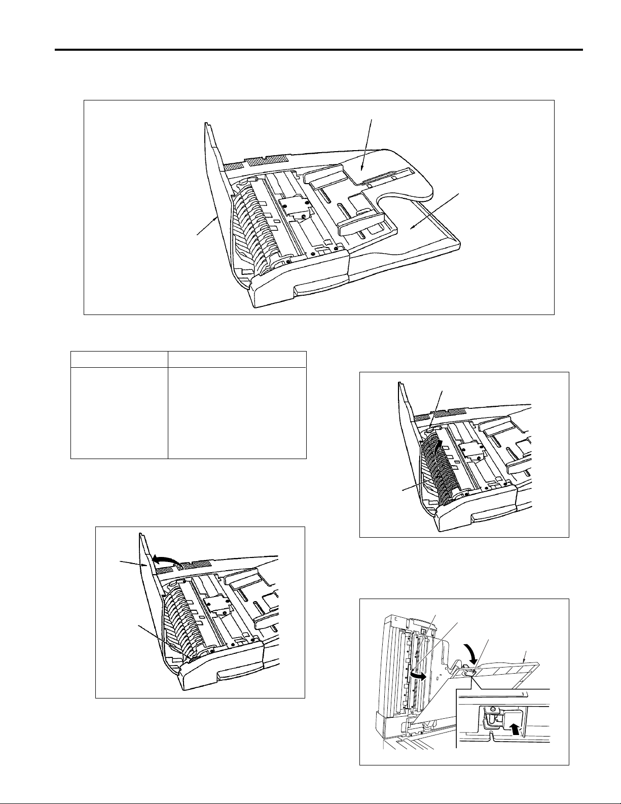
EXTERNAL SECTION
Composition
Jam access cover
DF-314
Original feed tray
Original exit tray
Mechanisms
Mechanism System
Jam release* Jam access cover
Reversal guide open/close lever
RADF Main body open/close
Knob
Exit-guide open/close lever
Platen separation lever
* Jam removal
If a jam occurs at the original feed, open the Jam
access cover and turning the knob closer to you
withdraw the sheet.
Jam
access
cover
Knob
If a jam occurs in the reversal section, open the
reversal guide with the reversal guide open/close
lever and withdraw the sheet.
Reversal guide open/close lever
Reversal
guide
If a jam occurs in the conveyance section, open
the exit tray (using the platen separation lever)
and the exit guide (using the exit-guide open/
close lever) and withdraw the sheet.
Exit guide
Exit guide open/close lever
Platen separation lever
Original exit tray
7
Page 16
DF-314
ORIGINAL FEED/REVERSAL/ORIGINAL EXIT SECTION
Composition
Jam access cover
Exit SD (SD303)
Original feed unit
Roller pressure SD (SD302)
Original feed tray
Mechanisms
Mechanism System
Original feed Feed roller
Double feed prevention Separation roller
Double feed prevention
Roller
Original conveyance Original conveyance rollers
Original reverse and Reversal guide
feed *1
Original exit path Original exit guide
section *2
Original exit tray
Original
reversal
motor
(M303)
Original conveyance
motor (M302)
Original reversal motor (M303)
Original feed motor (M301)
Reversal guide
Reversal guide
*1: Reversed original feed
During double-side copying, in order to reverse
the original the paper feed path is switched by the
reversal guide, the paper is conveyed to the
reverse mechanism and is reversed.
8
Page 17
DF-314
*2: Original exit path switching
In the case of a two-sided copy, the paper exit
guide changes over the paper feed path so as to
either exit the original directly, or feed the original
to the reversal section in order to read it once
again.
Exit guide
Exit guide
Exit SD (SD303)
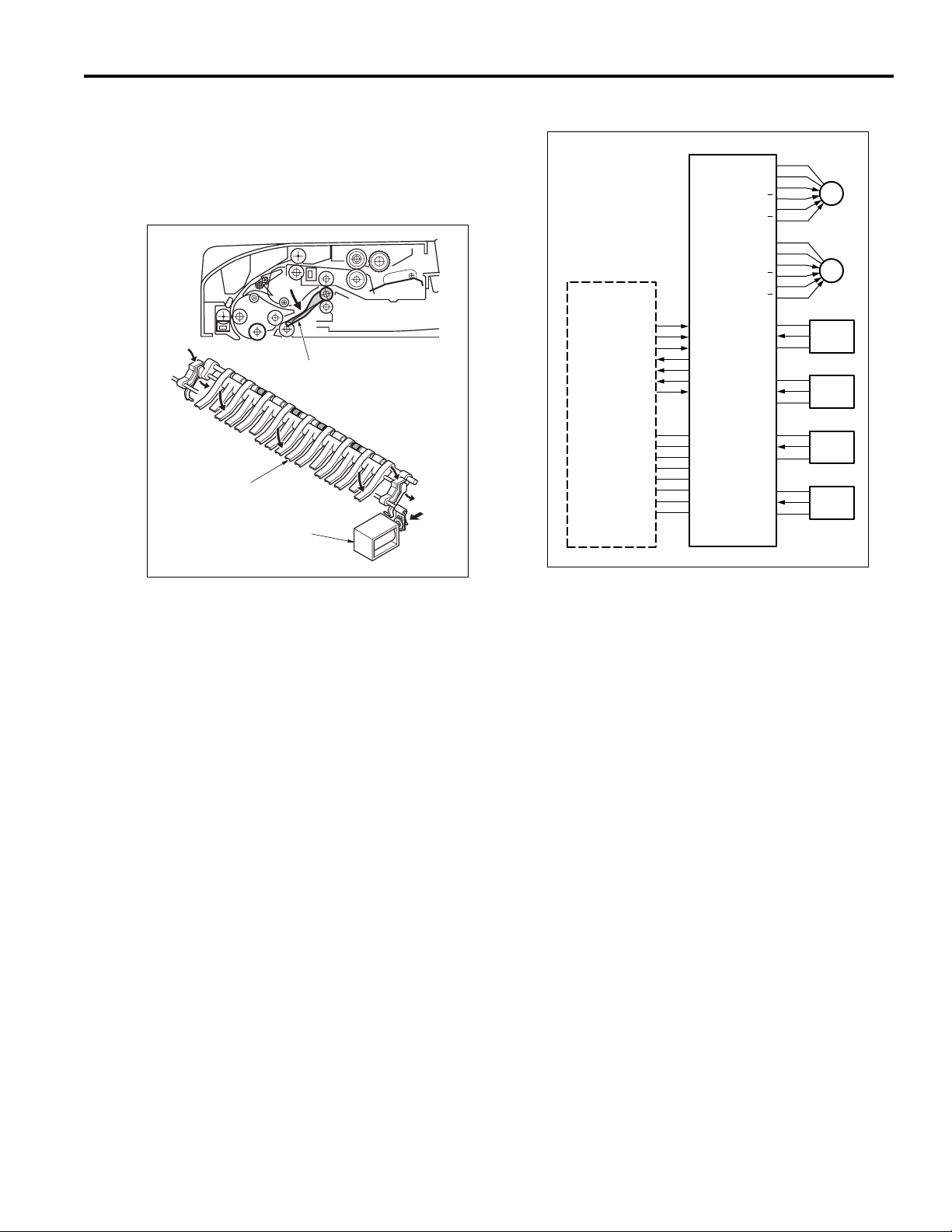
Original Feed/Conveyance/Scan Control
24VDC
24VDC
MAIN BODY
M TXD
M REQ
S ACK
M ACK
S TXD
S REQ
24VDC
24VDC
PGND
PGND
5VDC
SGND
SGND
5VDC
M301 OUT A
M301 OUT A
M301 OUT B
M301 OUT B
24VDC
24VDC
M302 OUT A
M302 OUT A
M302 OUT B
M302 OUT B
5VDC
PS301
SGND
5VDC
DF CB
PS303
SGND
5VDC
PS311
SGND
5VDC
PS312
SGND
VV
M301
M302
PS301
PS303
PS311
PS312
Original feed is achieved by the transmission of the
M301(original feed motor) drive power to the original feed
roller, separation roller and registration roller. Original
conveyance is achieved by the transmission of the M302
(original conveyance motor) drive power to the original
conveyance roller.
The M301 and M302 are controlled by the DFCB (RADF
control board).
9
Page 18

DF-314
1. Operation
a. Original feed
Original feed is started by the transmission of the
M301 drive power to the original feed roller,
separation roller and paper lift-up plate.
b. 1st original pre-feed
When the copy button is pressed, the M301 starts
original pre-feed, and when the conveyed original
arrives at PS311, M301 stops temporarily after a
specified time. M301 then rotates in reverse, turning
the registration roller so that feeding starts again.
The original passes PS311, so that PS311 turns
OFF. A predetermined time interval after PS311
turns OFF, M301 also turns OFF.
c. 2nd original pre-feed
When there is still an original in the original feed tray,
M301 starts after a specified time after PS311 has
turned OFF, and starts the pre-feed from after the
second sheet. The original is conveyed in the same
way as in the 1st. original pre-feed.
2. Signals
a. Input signals
(1) PS301(PS301 -> DF CB)
Original feed tray no-paper detection signal
[L] :Original
[H] : No original
(2) PS303(PS303 -> DF CB)
Original exit section original detection signal
[L] : No original
[H] : Original
(3) PS311(PS311 -> DF CB)
Original conveyance roller entrance original
detection signal
[L] : No original
[H] : Original
(4) PS312(PS312 -> DF CB)
Original detection signal from detector in front of
scan position
[L] : No original
d. Scanning operation (except last original)
When the original arrives at PS311, M302 starts after
a specified time has elapsed and the original is
conveyed to the read section.
Scanning of the original is achieved when the
original passes over the surface of the slit glass of
the main body optical section.
When the original arrives at PS312, scanning is
started after a specified time has elapsed, and when
PS312 turns OFF after the original has passed,
scanning is stopped after the lapse of a fixed period
of time.
e. Scanning operation (last original)
During the scanning operation, when PS301(no
original detect PS) turns OFF, the original currently
being scanned is judged to be the last original. When
the last original has passed PS311, M301 turns OFF
after the lapse of a fixed period of time, and when the
original has passed PS303 (original exit PS), M302
turns OFF after a specified time.
[H] : Original
(5) M TXD (MAIN BODy -> DF CB)
Serial data line; informs RADF of the operating state
of the main body's CB
(6) M REQ (MAIN BODY -> DF CB)
Transmission request signal from main body to
RADF
(7) S ACK (MAIN BODY -> DF CB)
Transmission OK signal from main body to RADF
10
Page 19

DF-314
b. Output signals
–
(1 ) M301 OUT A, M301 OUT A
, M301 OUT B,
M301 OUT B– (DF CB -> M301)
M301 drive control signal
24V
0V
–
(2) M302 OUT A, M302 OUT A
, M302 OUT B,
M302 OUT B– (DF CB -> M302)
M302 drive control signal
24V
0V
(3) M ACK (DF CB -> MAIN BODY)
Transmission OK signal from RADF to main body
(4) S TXD (DF CB -> MAIN BODY)
Serial data line; informs the main body's CB of the
RADF operating state
(5) S REQ (DF CB -> MAIN BODY)
Transmission request signal from RADF to main
body.
Original Exit/Reversal and Conveyance Control
24VDC
24VDC
M301 OUT A
M301 OUT A
M301 OUT B
M301 OUT B
24VDC
24VDC
M302 OUT A
M302 OUT A
M302 OUT B
M302 OUT B
24VDC
24VDC
M303 OUT A
M303 OUT A
M303 OUT B
M303 OUT B
MAIN BODY
M TXD
M REQ
S ACK
M ACK
S TXD
S REQ
24VDC
24VDC
PGND
PGND
5VDC
SGND
SGND
5VDC
VV
DF CB
24VDC
SD302
24VDC
SD303
5VDC
PS311
SGND
5VDC
PS312
SGND
The exit guide used in exit path switching is driven by the
SD303 (exit SD).
M301
M302
M303
SD302
SD303
PS311
PS312
Reversal conveyance drive in double-side copy mode is
performed by the M303 (original reversal motor). The
reversal roller pressure/freeing used in reversal original
feed is performed by the SD 302 (roller pressure SD).
M303, SD302 and SD303 are controlled by the DF CB
(RADF control board).
11
Page 20

DF-314
1. Operation
a. Original exit operation
During single side copying and face side copying in
double-side copying, the exit guide is raised because
SD303 is OFF. For this reason, an original which has
been read is conveyed to the exit section.
b. Reversal original exit operation
During back side copying in double side copying, the
original is conveyed to the scanning section by
reverse rotation of M303 and nomal rotation of M302.
When PS312 turns ON, SD302 turns OFF, and
reversal roller paper pressure conveys the freed
original to the reversal section.
c. Reversal original feed operation
After PS312 has detected the rear edge of the
original, SD302 turns ON after a specified time has
elapsed and the reversal roller applies pressure
(seizes, pinches) to the original. After that, M303
stops, but then immediately reverses and starts the
original feed operation of the original face side scan.
2. Signals
a. Output signals
(1 ) M301 OUT A, M301 OUT A
M301 OUT B– (DF CB -> M301)
M301 drive control signal
24V
0V
(2) SD302 (DF CB -> SD302)
SD302 drive control signal
[L] :ON
[H] : OFF
(3) SD303 (DF CB -> SD303)
SD303 drive control signal
[L] : ON
[H]: OFF
–
, M301 OUT B,
d. Pre-feed operation of next original when
reading back side of original
PS311 turns OFF once the first original has passed,
and after a specified period of time has elapsed,
starts the pre-feed operation for the 2nd. original.
After the elapse of a specified time after the 2nd.
original has arrived at PS311, M301 (original feed
motor) stops.
e. Overlap control
When scanning of the back side of the first original
sheet has been completed and the leading edge of
the original fed from the reversal section reaches
PS312, M301 turns ON and feeding of the second
original starts. At this time, the SD302 goes OFF,
causing the pressure on the reversal roller and the
paper exit roller to be released. This enables the first
and second originals to pass over each other in
opposite directions in the reversal unit.
12
Page 21
DF-314
Original Size Detection Control
DF CB
5VDC
PS306
SGND
5VDC
PS307
SGND
5VDC
PS311
SGND
5VDC
VR301
SGND
PS306
PS307
PS311
VR301
M TXD
M REQ
S ACK
M ACK
S TXD
S REQ
VV
24VDC
24VDC
PGND
PGND
5VDC
SGND
SGND
5VDC
MAIN BODY
Size detection on an original set in the original feed tray is
performed by PS306 (original size detect PS1), PS307
(original size detect PS2), and VR301 (size detect VR).
Note that the DF CB includes internal nonvolatile memory
that stores timing data, size-detection reference values,
and other such data.
b. Original size detection in mixed-original
modes and Z-fold-original modes (1st
sheet)
(1) Drum axis direction size detection
The width of the maximum sized original being
mixed-loaded is detected by the position of the
VR301 guide plate.
(2) Size detection in original feed direction
Original feed direction size is detected during PS311
ON time (the time taken by the original to pass
PS311).
(3) Operation of size detection in original feed
direction
When original re-feed is started by the registration
roller, when a specified time has elapsed after
PS311 turning ON, M303 (original reversal motor)
turns ON and conveys the original to the reversal
section.
PS311 (Original registration PS)
1. Operation
a. Normal copy mode
The DF CB detects the original size when the signals
described below combine.
(1) Drum axis direction size detection
VR301 resistance value changes in the position
where the guide plate contacts VR301. The width of
the original is detected by the resistance value.
(2) Size detection in original feed direction
The length of the original is detected by the ON/OFF
states of PS306 and PS307.
Conveyance to the scanning section is performed by
M303 reverse rotation.
Conveyance or scanning thereafter for both single
and double-sided originals is performed by the same
operation as for double-side copy mode. However in
single-side copying, the back side of the original
passes the scanning section without being scanned
and is conveyed to the reverse section.
Original size detection operation after the 2nd.
original starts after the completion of the exit of the
first original.
13
Page 22

DF-314
c. Allowed size combination
( : same size, : same series, : different series,
: no mixed loading, : not supported)
(1) AB series
Standard originals (the maximum original size detected
by the guide plate)
Other originals A3 A4 B4 B5 A4R A5 B5R A5R
A3
A4
B4
B5
A4R
A5
B5R
A5R
(2) Inch series
Standard originals (the maximum original size
detected by the guide plate)
Other originals 11x17 8.5x11 8.5x14 8.5x11R 8.5x5.5 8.5x5.5R
11 x 17
8.5 x 11
8.5 x 14
8.5 x 11R
8.5 x 5.5
8.5 x 5.5R
2. Signals
a. Input signals
(1) PS306 (PS306 -> DF CB)
Detection of original's length
[1] :Original
[2] :No original
(2) PS307 (PS307 -> DF CB)
Detection of original's length
[1] :Original
[2] :No original
(3) VR301 (VR301 -> DF CB)
Detection of original's width
14
Page 23

DISASSEMBLY/ASSEMBLY
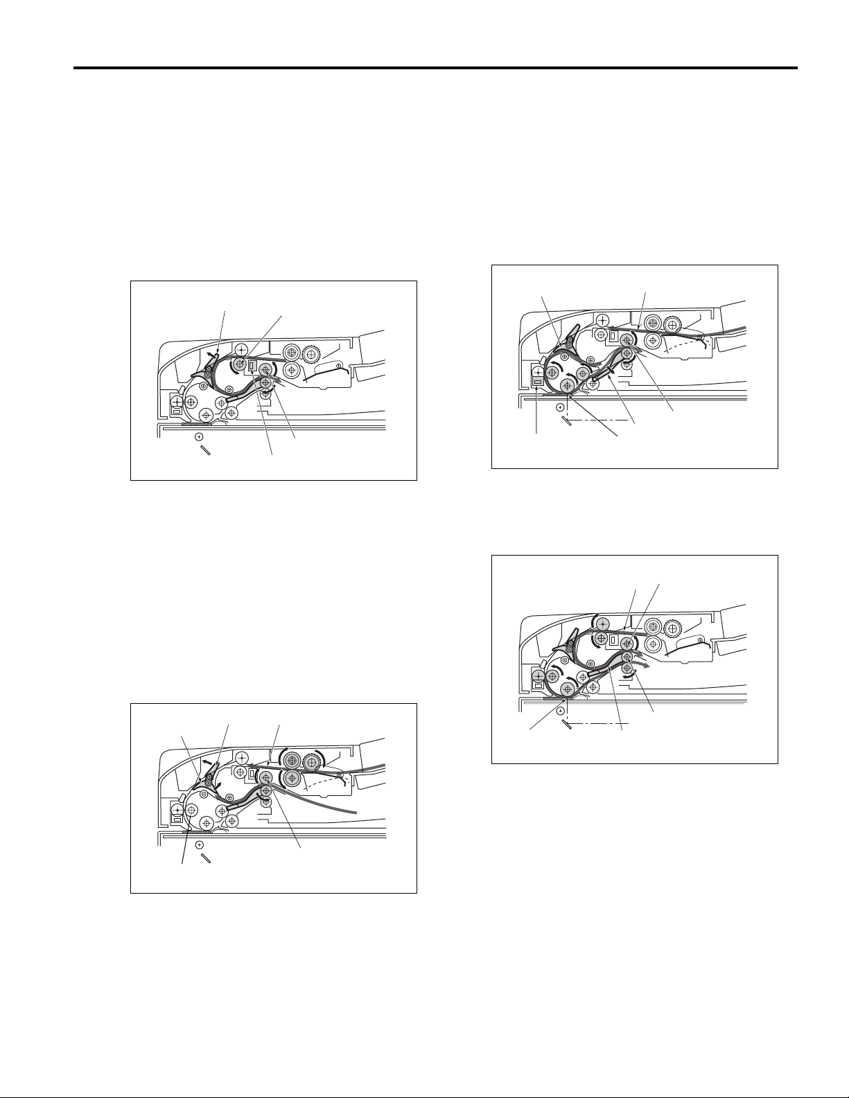
Caution: Make sure the power plug is taken
out of the socket.
Replacing Feed Roller/A
(1) Open jam access cover.
(2) Take out the 2 fixed screws and lifting the feed unit
lightly draw it forwards towards yourself and
remove it.
Set screws
Feed unit
DF-314
Replacing the Double-Feed Prevention Roller/A Assembly
(1) Open jam access cover.
(2) Remove feed unit.
Jam access cover
Feed unit
Double feed prevention roller
Feed unit
Feed roller/A
(3) Remove the E-rings on the ends of the paper-feed
unit (one E-ring on each end), and remove the feed
roller/A assy.
(4) Remove feed roller/A from the bearing of the feed
roller/A assy.
E-ring
Feed roller/A assy
E-ring
E-ring
E-ring
(6) Remove double feed prevention roller.
Double-feed prevention
roller/A assy
Double feed prevention roller
(5) Install by reversing the removal procedure.
Caution: When installing the feed unit, insert the
unit in order to fit the D cut side on the
drive shaft in the coupling.
15
Page 24

DF-314
(4) Remove the E-ring from the double-feed prevention
roller/A assy.
(5) Pull out the double-feed prevention roller/A assy.
E-ring
E-ring
Paint mark
Double-feed prevention
roller/A assy
(6) Install by reversing the removal procedure.
Caution: When installing the double-feed prevention
roller, make sure you install it in the correct
direction.
Replacing the Read Roller
(1) Remove the 3 set screws, and remove the cover.
Set screws
Cover
(3) Move the rear roller upward, then take out the pin and
remove the gear. Move the lower bearing, then pull
out the shaft of the read roller.
Gear
Pin
Read
roller
Bearing
(4) Reinstall the read roller in the opposite sequence
to removal.
Caution: Use glass cleaner to clean the roller if it is
dirty.
Set screw
(2) Remove the set screw, and remove the guide.
Next, remove the e-ring at the top of the read roller
and also the bearing at the bottom together with
the e-ring securing it.
Set screws
Guide
E-ring
E-ring
16
Page 25

DF-314 ELECTRICAL PARTS LAYOUT DRA WING
M301 Original feed motor
M303 Original reversal motor
M302 Original conveyance motor
DFCB DF control board
DF-314
PS303 Original exit PS
PS312 Original feed PS
VR301 Size detect VR
PS307 Original detect PS1
PS311 Original registration PS
PS306 Original detect PS2
SD302 Roller pressure SD
PS305 Cover open/close detect PS
PS304 RADF open/close detect PS
17
PS301 No original detect PS
SD303 Exit SD
Page 26

DF-314
DF-314 CONNECTOR LAYOUT DRA WING
CN130 (W:6pin)
CN132 (W:6pin)
CN131 (W:6pin)
CN200 (GY:160pin)
CN123 (W:3pin)
CN121 (W:3pin)
CN117 (W:3pin)
CN116 (W:3pin)
CN1 (18pin)
CN3 (7pin)
CN6 (15pin)
CN5 (8pin)
CN4 (9pin)
DFCB
CN7 (30pin)
CN2 (22pin)
CN122 (W:3pin)
CN113 (W:3pin)
CN114 (W:3pin)
18
CN115 (W:3pin)
CN136 (W:2pin)
CN111 (W:3pin)
CN105 (W:3pin)
CN137 (W:2pin)
Page 27

TIME CHART (8.5X1 1, 1-SIDED ORIGINAL, 3 SHEETS)
DF-314
01234567
)
sec
(
Time
Item
No original detect PSPS301
Symbol
Original registration PSPS311
Original feed PS
PS312
F
Valid (Scan)
250mm/s
R
260mm/s
Original feed
motor
M301
19
R
140mm/s
F
260mm/s
Original
conveyance
motor
M302
F
140mm/s
F
R
Original
reversal motor
M303
Roller pressure SD
SD302
Exit SDSD303
Original exit PS
PS303
Page 28

DF-314
TIME CHART (8.5X11, 2-SIDED ORIGINALS, 2 SHEETS)
01234567891011121314
)
sec
(
Time
Item
Symbol
No original detect PSPS301
Original registration PSPS311
Original feed PS
PS312
F
Valid (Scan)
250mm/s
R
260mm/s
Original feed
motor
M301
R
20
F
140mm/s
260mm/s
Original
conveyance
motor
M302
F
140mm/s
F
Original
reversal
motor
M303
R
Roller pressure SD
Exit SDSD303
SD302
Original exit PS
PS303
Page 29

DF-314 OVERALL WIRING DIAGRAM
21
[HOW to see the diagram]
1. The signals shown reflect levels present under normal idling
conditions with the main switch turned ON.
2. Wiring symbols in the figure are as follows.
1) @@@@ is Connector
2) @@@is ribbon cable
RC
3. Signal symbols in the figure are as follows .
High active
H
L
Low active
Analog signal
*
Pulse signal
P
Page 30

This page left blank intentionally.
22
Page 31

PARTS CATALOG
Model
DF-314
SEPTEMBER 2002
THIRD EDITION
KONICA BUSINESS TECHNOLOGIES, INC.
Page 32

Page 33

How to use this catalog
This parts catalog includes illustrations and part numbers for all replacement parts and assemblies used in this model.
Model-specific parts are identified in the illustrations with reference
numbers. Use the reference number to locate the corresponding part
number on the facing page.
Common hardware items, such as screws, nuts, washers, and pins, are
identified in the illustrations with reference letters. Use the reference letter to locate the corresponding part number on the hardware listing in the
lower right hand corner of the facing page.
If you know a part number, but don’t know where the part is used, use
the numerical index to determine the page number and reference number for that part. Because some common parts are used in several
places, there may be more than one entry. Refer to the illustrations to see
where the part may be used.
If you know a part’s description, but don’t know where to look to find
the part number, use the alphabetical index to determine likely page and
reference numbers. Then look at the illustrations to determine that you
have identified the correct part. Locate the part number using the listing
on the opposite page.
Retail pricing that appears with the numerical index, while valid when
this catalog was printed, is subject to change without notice. The prices
are only suggested prices and are provided only for reference. Dealers
may determine their own selling prices. For up-to-date pricing, refer to
current Konica price lists or contact the Konica Parts Distribution Center.
How to order parts
Use standard Konica parts ordering procedures to obtain these parts.
For ordering options, contact Konica’s Parts Distribution Center.
When ordering parts, be sure to specify part numbers exactly as listed in
this catalog.
NOTE: Electrical parts may include previously used components.
Model DF-314 Konica Business Technologies, Inc. Page iii
3rd Edition September, 2002
Page 34

This page left blank intentionally.
Page iv Konica Business Technologies, Inc. Model DF-314
September, 2002 3rd Edition
Page 35

How to use this catalog . . . . . . . . . . . . . . . . . . . . . . . . . iii
Contents . . . . . . . . . . . . . . . . . . . . . . . . . . . . 1
DF-314 . . . . . . . . . . . . . . . . . . . . . . . . . . . . 2
Wiring . . . . . . . . . . . . . . . . . . . . . . . . . . . . 18
Alphabetical index . . . . . . . . . . . . . . . . . . . . . . . . . . . 21
Numerical index, Retail price list . . . . . . . . . . . . . . . . . . . . 23
Contents
Model DF-314 Konica Business Technologies, Inc. Page 1
3rd Edition September, 2002
Page 36

DF-314
Page 2 Konica Business Technologies., Inc. Model DF-314
September, 2002 3rd Edition
Page 37

REF. PART NUMBER DESCRIPTION
NO.
1 13GL12030 Front cover
2 13GL76080 Shaft holder/E
3 13GL45600 Positioning stopper/front
4 13GL46160 Lock catch
5 13GL10110 Hinge/L
6 13GL46030 Original cover hinge
7 13GL10210 Hinge bottom plate/R
8 * Not used
9 13GL12020 Rear cover
10 13GL10150 Hinge auxiliary plate/1
11 13GL10220 Hinge positioning shaft/R
12 13GL46100 Lock spring
13 13GL46080 Lock lever/A
14 13GL10320 Hinge stopper
15 13GL10310 Hinge cover sheet/1
16 13G8-9011 RADF control unit
17 13GL10250 Hold spring/B
18 13GL12050 Front auxiliary cover
19 13GL97081 Cleaning label/1
20 13GL10200 Hinge upper plate/R
21 13GL10191 Hinge mount plate/R
22 13GL90042 RADF wiring/4
23 13GL46710 Hinge plate
24 13GL-4800 Original exit tray assembly
HARDWARE
REF.
LTR.
a 00Z184061
b 00Z183041
c 00Z510501
d 00Z620501
e 00Z610501
f 00Z670406
g 00Z193041
h 00Z920034
k 00Z193062
m 00Z253081
n 00Z254101
p 00Z670306
q 00Z925103
r 00Z926251
s 00Z183042
PART
NUMBER
Model DF-314 Konica Business Technologies., Inc. Page 3
3rd Edition September, 2002
Page 38

DF-314
Page 4 Konica Business Technologies., Inc. Model DF-314
September, 2002 3rd Edition
Page 39

REF. PART NUMBER DESCRIPTION
NO.
1 13GL45151 Driving release roller/A
2 13GL46720 Fixing plate
3 113620600 Pin (A)
4 13GL76590 Conveyance driving pulley/D (Z=42)
5 13GL40500 Slide sheet/A
6 466076020 Paper feeding shaft holder
7 13GL45840 Toque rotary spring
8 13GL77550 Driving reverse belt (L=60/96)
9 13GL76600 Conveyance driving pulley/E (Z=17)
10 13GL76610 Conveyance driving pulley/F (Z=17)
11 13GL40350 Connecting collar
12 13GL40341 Toque limiter/B
13 13GL-4050 Double feed preventive roller/A assembly
14 13GL10300 Rotary spring
15 13GL40050 Double feed preventive plate
16 * Not used
17 12ER40350 Sticking part
18 13GL46661 Paper exit detecting plate
19 13GL40380 Stopper part/A
20 13GL-4041 Double feed preventive roller
21 13GL82511 Solenoid/A
22 13GL-4012 Paper feed guide plate/lower assembly
23 13GL45210 Driving release lever/1
24 13GL40550 Conveyance auxiliary sheet
25 13GL45240 Conveyance guide plate/B
26 13GL46690 Neutralizing brush
27 13GL45200 Pressure spring
28 13GL45190 Pressure part
29 13GL40240 Double feed preventive spring
30 13GL15212 Wiring cover/2
31 13GL15240 Reversal shaft holder
32 13GL45591 Electrify preventive sheet
33 08AA85510 Photosensor
34 13QA85510 Sensor/1
35 13GL45850 Pressure spring/A
HARDWARE
REF.
LTR.
a 00Z183101
c 00Z193041
d 00Z921930
e 00Z193061
f 00Z670406
h 00Z926251
k 00Z194081
PART
NUMBER
Model DF-314 Konica Business Technologies., Inc. Page 5
3rd Edition September, 2002
Page 40

DF-314
Page 6 Konica Business Technologies., Inc. Model DF-314
September, 2002 3rd Edition
Page 41
REF. PART NUMBER DESCRIPTION
NO.
1 13GL40250 Original pressure sheet
2 12QV40190 Paper feed roller/B
3 12QV40340 Paper supply rubber
4 13GL76021 Shaft holder/B
5 13GQ76020 Shaft holder/A
6 13GL40060 Paper feed mount part
7 12QV76590 Feeding pulley/A
8 13GL77540 Feeding belt (L=92)
9 13GL40260 Sticking part
10 454078050 Pin
11 13GL76030 Shaft holder/C
12 13GL40110 Paper feed roller/A
13 08AA85510 Photosensor
14 12QV76600 Feeding pulley/B
15 12QV40740 Belt regulating part
16 13GL90012 RADF wiring/1
17 13GL40320 Paper feed coupling/A
18 13GL40330 Paper feed coupling spring
19 13GL76520 Paper feed driving pulley (Z=36)
20 466076020 Paper feeding shaft holder
21 13GL40290 Remained detecting actuator/B
22 13GL76010 Shaft holder/A
23 13GL40070 Paper feed guide plate/B
24 13GL40270 Remained detecting actuator/A
25 13GL-1740 Driving motor/2 assembly
26 13GL40400 Toque limiter/C
27 13GL76660 Original pressure pulley (Z=40)
28 13GL40460 Original pressure spring/A
29 13GL77511 Paper feed belt/A (L=260)
30 13GL77581 Original pressure belt (L=112)
31 13GL-4062 Feeding unit
HARDWARE
REF.
LTR.
PART
NUMBER
a 00Z921930
b 00Z193041
c 00Z670406
d 00Z712106
e 00Z183041
h 00Z670206
Model DF-314 Konica Business Technologies., Inc. Page 7
3rd Edition September, 2002
Page 42

DF-314
Page 8 Konica Business Technologies., Inc. Model DF-314
September, 2002 3rd Edition
Page 43

REF. PART NUMBER DESCRIPTION
NO.
1 13GL12040 Side cover
2 13GL45620 Adjusting lever/front
3 13GL45570 Adjusting spring/A
4 56AA85520 Conveyance photosensor
5 13GL90031 RADF wiring/3
6 13GL77521 Reading drive belt (L=332)
7 13GL45040 Conveyance driven roller/A
8 13GL15060 Pulley shaft/A
9 13GL45060 Conveyance driven spring/A
10 13GL45031 Conveyance driving roller/A
11 13GL45530 Reading shaft holder/front
12 13GL45510 Reading guide plate
13 13GL45540 Reading shaft holder/Rear
14 466078010 Pin A
15 13GL76640 Reading connect pulley/1 (Z=23)
16 13GL77571 Reading connect belt (L=94)
17 13GL76650 Reading connecting pulley/2 (Z=23)
18 454078050 Pin
19 13GL45521 Reading roller
20 13GL45110 Conveyance driving roller/B
21 13GL45140 Conveyance driven spring/B
22 13GL76040 Shaft holder/F
23 13GL45070 Conveyance guide part/upper
24 13GL45120 Conveyance driven roller/rear
25 13GL45250 Conveyance driven roller/middle
26 13GL45100 Conveyance guide part/3
27 13GL45090 Conveyance guide part/2
28 13GL45080 Conveyance guide part/1
29 13GL45130 Conveyance driven shaft/B
30 13GL75010 Shaft holder/G
31 13GL45011 Conveyance guide part/C
32 13GL76630 Jam handling pulley (Z=34)
33 12ER40350 Sticking part
34 13GL15040 Idler pulley/A
35 25AA48670 Belt hold plate/B
36 13GL-1730 Driving motor/1 assembly
37 13GL76570 Conveyance driving pulley/B (Z=48)
38 113620600 Pin (A)
39 13GL76671 Conveyance driving pulley/G (Z=48)
HARDWARE
REF.
LTR.
a 00Z193041
b 00Z670406
c 00Z670306
d 00Z670606
e 00Z193061
f 00Z183041
g 00Z193062
h 00Z163061
PART
NUMBER
Model DF-314 Konica Business Technologies., Inc. Page 9
3rd Edition September, 2002
Page 44

DF-314
Page 10 Konica Business Technologies., Inc. Model DF-314
September, 2002 3rd Edition
Page 45

REF. PART NUMBER DESCRIPTION
NO.
1 13GL76060 Shaft holder/D
2 13GL73020 Open-close actuator
3 13GL73010 Open-close part
4 13GL73030 Detecting spring
5 13GL46780 Paper exit guide spring/front
6 13GL-4850 Paper exit guide stopper/A assembly
7 13GL-1750 Driving motor/3assembly
8 13GL76580 Conveyance driving pulley/C (Z=36)
9 113620600 Pin (A)
10 13GL97050 Jam release label
11 13GL45161 Driving release roller/B
12 466078010 Pin A
13 13GL46600 Paper exit driving roller/A
14 13GL15120 Tension spring/B
15 13GL-4860 Paper exit guide stopper/B assembly
16 13GL46750 Paper exit guide spring/rear
17 13GL15030 Tension spring/A
18 13GL46060 Collar/A
19 13GL77531 Conveyance driving belt (L=204)
20 13GL46610 Paper exit driven roller
21 13GL46260 Paper exit pressure spring/rear
22 13GL46640 Paper exit actuator/1
23 13GL46680 Paper exit detecting spring
24 13GL46650 Paper exit actuator/2
25 13GL-4830 Paper exit connecting shaft assembly
26 13GL46250 Paper exit pressure spring/front
27 13GL46700 Spring cover
28 13GL46630 Paper exit driven spring
29 13GL-4870 Paper exit guide plate/A assembly
30 13GL46180 Paper exit reinforcing plate
31 13GL-1570 Tension plate/A assembly
32 13GL15260 Idler pulley/C
33 13GL15190 Tension spring/B
HARDWARE
REF.
LTR.
a 00Z670406
b 00Z670306
c 00Z253081
d 00Z670206
e 00Z193041
f 00Z183041
g 00Z610301
h 00Z193081
i 00Z252081
PART
NUMBER
Model DF-314 Konica Business Technologies., Inc. Page 11
3rd Edition September, 2002
Page 46

DF-314
Page 12 Konica Business Technologies., Inc. Model DF-314
September, 2002 3rd Edition
Page 47

REF. PART NUMBER DESCRIPTION
NO.
1 13GL45722 Jam release arm/F
2 13GL45381 Conveyance guide spring
3 13GL45791 Spring fulcrum shaft
4 13GL-4532 Conveyance guide part assembly
5 * Not used
6 454078050 Pin
7 13GL-1541 Paper exit solenoid assembly
8 13GL46591 Solenoid support plate
9 13GL46550 Paper exit guide lever/A
10 13GL-4581 Conveyance guide cam assembly
11 13GL45630 Conveyance neutralizing sheet/A
12 13GL45732 Jam release arm/R
13 466076020 Paper feeding shaft holder
14 13GL45430 Conveyance driven roller
15 13GL40530 Double feed release spring/A
16 13GL45421 Conveyance guide part/B
17 13GL40490 Support part/A
18 13GL46560 Paper exit guide lever/B
19 13GL76080 Shaft holder/E
21 13GL45411 Conveyance guide part/A
22 25SA82651 Paper exit solenoid
23 13GL40480 Double feed release plate/A
24 13GL40510 Release wire/A
25 13GL76560 Conveyance driving pulley/A (Z=18)
26 13GL15231 Toque limiter/A
27 08AA85510 Photosensor
HARDWARE
REF.
LTR.
a 00Z193061
b 00Z253081
c 00Z163061
d 00Z670406
g 00Z162061
h 00Z193041
j 00Z163081
k 00Z193041
PART
NUMBER
Model DF-314 Konica Business Technologies., Inc. Page 13
3rd Edition September, 2002
Page 48

DF-314
Page 14 Konica Business Technologies., Inc. Model DF-314
September, 2002 3rd Edition
Page 49

REF. PART NUMBER DESCRIPTION
NO.
1 13GL40390 Hold spring/A
2 13GL76510 Registration unit driving puley (Z=48)
3 13GL40160 Registration unit pressure spring
4 13GL76620 Jam handling knob (Z=17)
5 13GL40140 Registration unit driven roller
6 13GL40410 Registration unit driven roller
7 13GL77561 Jam handling belt (L=66)
8 13GL40100 Shaft support part
9 13GL40430 Cleaning part/A
10 13GL40420 Paper feed cleaning part
11 13GL77511 Paper feed belt/A (L=260)
12 13GL40130 Registration unit driving roller
13 13GL-1202 Open-close cover assembly
14 090075530 Bearing
15 55GA97301 Glass cleaning label
16 13QA41430 Sensor support sheet
HARDWARE
REF.
LTR.
a 00Z193041
b 00Z670606
c 00Z253081
PART
NUMBER
Model DF-314 Konica Business Technologies., Inc. Page 15
3rd Edition September, 2002
Page 50

DF-314
Page 16 Konica Business Technologies., Inc. Model DF-314
September, 2002 3rd Edition
Page 51

REF. PART NUMBER DESCRIPTION
NO.
1 13GL42040 Regulating side plate/rear
2 13GL42030 Regulating side plate/front
3 13GL97030 Paper feed label/A
4 13GL42050 Wiring cover
5 396040611 Rack
6 55GA42210 Rack
7 13GL-1580 Support plate/A assembly
8 13GL97070 Original regulating label/A
9 466077130 Pinion
10 * Not used
11 13FG-9330 Size detecting board assembly
12 13GL77030 Detecting pinion (Z=124)
13 13QA85520 Sensor/2
14 13GL90021 RADF wiring/2
15 13GL97040 Paper feed label/B
16 13GL42014 Paper feed tray
17 13GL42022 Paper feed cover/lower
HARDWARE
REF.
LTR.
a 00Z193041
b 00Z253081
PART
NUMBER
Model DF-314 Konica Business Technologies., Inc. Page 17
3rd Edition September, 2002
Page 52

Wiring
Page 18 Konica Business Technologies., Inc. Model DF-314
September, 2002 3rd Edition
Page 53

REF. PART NUMBER DESCRIPTION
NO.
1 13GL90012 RADF wiring/1
2 13GL90021 RADF wiring/2
3 13GL90031 RADF wiring/3
4 13GL90042 RADF wiring/4
5 13GL97100 Standard sheet
Model DF-314 Konica Business Technologies., Inc. Page 19
3rd Edition September, 2002
Page 54

This page left blank intentionally.
Page 20 Konica Business Technologies, Inc. Model DF-314
September, 2002 3rd Edition
Page 55

Alphabetical index
PART PAGE REF.
DESCRIPTION NO. NO.
A
Adjusting lever/front . . . . 9 2
Adjusting spring/A . . . . . 9 3
B
Bearing . . . . . . . . . . . 15 14
Belt hold plate/B . . . . . . 9 35
Belt regulating part . . . . . 7 15
C
Cleaning label/1 . . . . . . 3 19
Cleaning part/A . . . . . . 15 9
Collar/A . . . . . . . . . . 11 18
Connecting collar . . . . . 5 11
Conveyance auxiliary sheet 5 24
Conveyance driven roller . . 13 14
Conveyance driven roller/A 9 7
Conveyance driven
roller/middle . . . . . . 9 25
Conveyance driven roller/rear 9 24
Conveyance driven shaft/B . 9 29
Conveyance driven spring/A 9 9
Conveyance driven spring/B 9 21
Conveyance driving belt
(L=204) . . . . . . . . 11 19
Conveyance driving pulley/A
(Z=18) . . . . . . . . . 13 25
Conveyance driving pulley/B
(Z=48) . . . . . . . . . 9 37
Conveyance driving pulley/C
(Z=36) . . . . . . . . . 11 8
Conveyance driving pulley/D
(Z=42) . . . . . . . . . 5 4
Conveyance driving pulley/E
(Z=17) . . . . . . . . . 5 9
Conveyance driving pulley/F
(Z=17) . . . . . . . . . 5 10
Conveyance driving pulley/G
(Z=48) . . . . . . . . . 9 39
Conveyance driving roller/A 9 10
Conveyance driving roller/B 9 20
Conveyance guide cam
assembly . . . . . . . . 13 10
Conveyance guide part
assembly . . . . . . . . 13 4
Conveyance guide part/1 . 9 28
Conveyance guide part/2 . 9 27
Conveyance guide part/3 . 9 26
Conveyance guide part/A . 13 21
Conveyance guide part/B . 13 16
Conveyance guide part/C . 9 31
Conveyance guide part/upper 9 23
Conveyance guide plate/B . 5 25
Conveyance guide spring . 13 2
Conveyance neutralizing
sheet/A . . . . . . . . 13 11
Conveyance photosensor . 9 4
PART PAGE REF.
DESCRIPTION NO. NO.
D
Detecting pinion (Z=124) . . 17 12
Detecting spring . . . . . . 11 4
Double feed preventive plate 5 15
Double feed preventive roller 5 20
Double feed preventive
roller/A assembly . . . . 5 13
Double feed preventive spring 5 29
Double feed release plate/A 13 23
Double feed release spring/A 13 15
Driving motor/1 assembly . 9 36
Driving motor/2 assembly . 7 25
Driving motor/3 assembly . 11 7
Driving release lever/1 . . . 5 23
Driving release roller/A . . . 5 1
Driving release roller/B . . . 11 11
Driving reverse belt (L=60/96) 5 8
E
Electrify preventive sheet . . 5 32
F
Feeding belt (L=92) . . . . 7 8
Feeding pulley/A . . . . . . 7 7
Feeding pulley/B . . . . . . 7 14
Feeding unit . . . . . . . . 7 31
Fixing plate . . . . . . . . . 5 2
Front auxiliary cover . . . . 3 18
Front cover . . . . . . . . . 3 1
G
Glass cleaning label . . . . 15 15
H
Hinge auxiliary plate/1 . . . 3 10
Hinge bottom plate/R . . . . 3 7
Hinge cover sheet/1 . . . . 3 15
Hinge mount plate/R . . . . 3 21
Hinge plate . . . . . . . . . 3 23
Hinge positioning shaft/R . . 3 11
Hinge stopper . . . . . . . 3 14
Hinge upper plate/R . . . . 3 20
Hinge/L . . . . . . . . . . . 3 5
Hold spring/A . . . . . . . . 15 1
Hold spring/B . . . . . . . . 3 17
I
Idler pulley/A . . . . . . . . 9 34
Idler pulley/C . . . . . . . . 11 32
PART PAGE REF.
DESCRIPTION NO. NO.
J
Jam handling belt (L=66) . . 15 7
Jam handling knob (Z=17) . 15 4
Jam handling pulley (Z=34) . 9 32
Jam release arm/F . . . . . 13 1
Jam release arm/R . . . . . 13 12
Jam release label . . . . . . 11 10
L
Lock catch . . . . . . . . . 3 4
Lock lever/A . . . . . . . . . 3 13
Lock spring . . . . . . . . . 3 12
N
Neutralizing brush . . . . . 5 26
O
Open-close actuator . . . . 11 2
Open-close cover assembly 15 13
Open-close part . . . . . . 11 3
Original cover hinge . . . . 3 6
Original exit tray assembly . 3 24
Original pressure belt
(L=112) . . . . . . . . . 7 30
Original pressure pulley
(Z=40) . . . . . . . . . 7 27
Original pressure sheet . . . 7 1
Original pressure spring/A . 7 28
Original regulating label/A . 17 8
P
Paper exit actuator/1 . . . . 11 22
Paper exit actuator/2 . . . . 11 24
Paper exit connecting shaft
assembly . . . . . . . . 11 25
Paper exit detecting plate . . 5 18
Paper exit detecting spring . 11 23
Paper exit driven roller . . . 11 20
Paper exit driven spring . . . 11 28
Paper exit driving roller/A . . 11 13
Paper exit guide lever/A . . 13 9
Paper exit guide lever/B . . 13 18
Paper exit guide plate/A
assembly . . . . . . . . 11 29
Paper exit guide spring/front 11 5
Paper exit guide spring/rear 11 16
Paper exit guide stopper/A
assembly . . . . . . . . 11 6
Paper exit guide stopper/B
assembly . . . . . . . . 11 15
Paper exit pressure
spring/front . . . . . . . 11 26
Paper exit pressure
spring/rear . . . . . . . 11 21
Paper exit reinforcing plate . 11 30
Model DF-314 Konica Business Technologies, Inc. Page 21
3rd Edition September, 2002
Page 56

PART PAGE REF.
DESCRIPTION NO. NO.
Paper exit solenoid . . . . . 13 22
Paper exit solenoid assembly 13 7
Paper feed belt/A (L=260) . 7 29
Paper feed belt/A (L=260) . 15 11
Paper feed cleaning part . . 15 10
Paper feed coupling spring . 7 18
Paper feed coupling/A . . . 7 17
Paper feed cover/lower . . . 17 17
Paper feed driving pulley
(Z=36) . . . . . . . . . 7 19
Paper feed guide plate/B . . 7 23
Paper feed guide plate/lower
assembly . . . . . . . . 5 22
Paper feed label/A . . . . . 17 3
Paper feed label/B . . . . . 17 15
Paper feed mount part . . . 7 6
Paper feed roller/A . . . . . 7 12
Paper feed roller/B . . . . . 7 2
Paper feed tray . . . . . . . 17 16
Paper feeding shaft holder . 5 6
Paper feeding shaft holder . 7 20
Paper feeding shaft holder . 13 13
Paper supply rubber . . . . 7 3
Photosensor . . . . . . . . 5 33
Photosensor . . . . . . . . 7 13
Photosensor . . . . . . . . 13 27
Pin . . . . . . . . . . . . . 7 10
Pin . . . . . . . . . . . . . 9 18
Pin . . . . . . . . . . . . . 13 6
Pin (A) . . . . . . . . . . . 5 3
Pin (A) . . . . . . . . . . . 9 38
Pin (A) . . . . . . . . . . . 11 9
Pin A . . . . . . . . . . . . 9 14
Pin A . . . . . . . . . . . . 11 12
Pinion . . . . . . . . . . . . 17 9
Positioning stopper/front . . 3 3
Pressure part . . . . . . . . 5 28
Pressure spring . . . . . . . 5 27
Pressure spring/A . . . . . 5 35
Pulley shaft/A . . . . . . . . 9 8
R
RADF control unit . . . . . . 3 16
PART PAGE REF.
DESCRIPTION NO. NO.
RADF wiring/1 . . . . . . . 7 16
RADF wiring/1 . . . . . . . 19 1
RADF wiring/1 . . . . . . . 19 1
RADF wiring/2 . . . . . . . 17 14
RADF wiring/2 . . . . . . . 19 2
RADF wiring/3 . . . . . . . 9 5
RADF wiring/3 . . . . . . . 19 3
RADF wiring/4 . . . . . . . 3 22
RADF wiring/4 . . . . . . . 19 4
Rack . . . . . . . . . . . . 17 5
Rack . . . . . . . . . . . . 17 6
Reading connect belt (L=94) 9 16
Reading connect pulley/1
(Z=23) . . . . . . . . . 9 15
Reading connecting pulley/2
(Z . . . . . . . . . . . . 9 17
Reading drive belt (L=332) . 9 6
Reading guide plate . . . . 9 12
Reading roller . . . . . . . . 9 19
Reading shaft holder/Rear . 9 13
Reading shaft holder/front . 9 11
Rear cover . . . . . . . . . 3 9
Registration unit driven roller 15 5
Registration unit driven roller 15 6
Registration unit driving pull 15 2
Registration unit driving roll . 15 12
Registration unit pressure
spring . . . . . . . . . . 15 3
Regulating side plate/front . 17 2
Regulating side plate/rear . 17 1
Release wire/A . . . . . . . 13 24
Remained detecting
actuator/A . . . . . . . . 7 24
Remained detecting
actuator/B . . . . . . . . 7 21
Reversal shaft holder . . . . 5 31
Rotary spring . . . . . . . . 5 14
S
Sensor support sheet . . . . 15 16
Sensor/1 . . . . . . . . . . 5 34
Sensor/2 . . . . . . . . . . 17 13
Shaft holder/A . . . . . . . . 7 5
PART PAGE REF.
DESCRIPTION NO. NO.
Shaft holder/A . . . . . . . 7 22
Shaft holder/B . . . . . . . 7 4
Shaft holder/C . . . . . . . 7 11
Shaft holder/D . . . . . . . 11 1
Shaft holder/E . . . . . . . 3 2
Shaft holder/E . . . . . . . 13 19
Shaft holder/F . . . . . . . 9 22
Shaft holder/G . . . . . . . 9 30
Shaft support part . . . . . 15 8
Side cover . . . . . . . . . 9 1
Size detecting board
assembly . . . . . . . 17 11
Slide sheet/A . . . . . . . 5 5
Solenoid support plate . . 13 8
Solenoid/A . . . . . . . . 5 21
Spring cover . . . . . . . . 11 27
Spring fulcrum shaft . . . . 13 3
Standard sheet . . . . . . 19 5
Sticking part . . . . . . . . 5 17
Sticking part . . . . . . . . 7 9
Sticking part . . . . . . . . 9 33
Stopper part/A . . . . . . . 5 19
Support part/A . . . . . . 13 17
Support plate/A assembly . 17 7
T
Tension plate/A assembly . 11 31
Tension spring/A . . . . . 11 17
Tension spring/B . . . . . 11 14
Tension spring/B . . . . . 11 33
Toque limiter/A . . . . . . 13 26
Toque limiter/B . . . . . . 5 12
Toque limiter/C . . . . . . 7 26
Toque rotary spring . . . . 5 7
W
Wiring cover . . . . . . . . 17 4
Wiring cover/2 . . . . . . . 5 30
Page 22 Konica Business Technologies, Inc. Model DF-314
September, 2002 3rd Edition
Page 57

Numerical index
PART PAGE REF.
NUMBER NO. NO.
08AA85510 5 33
08AA85510 7 13
08AA85510 13 27
090075530 15 14
113620600 5 3
113620600 9 38
113620600 11 9
12ER40350 5 17
12ER40350 9 33
12QV40190 7 2
12QV40340 7 3
12QV40740 7 15
12QV76590 7 7
12QV76600 7 14
13FG-9330 17 11
13G8-9011 3 16
13GL-1202 15 13
13GL-1541 13 7
13GL-1570 11 31
13GL-1580 17 7
13GL-1730 9 36
13GL-1740 7 25
13GL-1750 11 7
13GL-4012 5 22
13GL-4041 5 20
13GL-4050 5 13
13GL-4062 7 31
13GL-4532 13 4
13GL-4581 13 10
13GL-4800 3 24
13GL-4830 11 25
13GL-4850 11 6
13GL-4860 11 15
13GL-4870 11 29
13GL10110 3 5
13GL10150 3 10
13GL10191 3 21
13GL10200 3 20
13GL10210 3 7
13GL10220 3 11
13GL10250 3 17
13GL10300 5 14
13GL10310 3 15
13GL10320 3 14
13GL12020 3 9
13GL12030 3 1
13GL12040 9 1
13GL12050 3 18
13GL15030 11 17
13GL15040 9 34
13GL15060 9 8
13GL15120 11 14
13GL15190 11 33
13GL15212 5 30
13GL15231 13 26
13GL15240 5 31
13GL15260 11 32
13GL40050 5 15
13GL40060 7 6
13GL40070 7 23
13GL40100 15 8
13GL40110 7 12
13GL40130 15 12
13GL40140 15 5
PART PAGE REF.
NUMBER NO. NO.
13GL40160 15 3
13GL40240 5 29
13GL40250 7 1
13GL40260 7 9
13GL40270 7 24
13GL40290 7 21
13GL40320 7 17
13GL40330 7 18
13GL40341 5 12
13GL40350 5 11
13GL40380 5 19
13GL40390 15 1
13GL40400 7 26
13GL40410 15 6
13GL40420 15 10
13GL40430 15 9
13GL40460 7 28
13GL40480 13 23
13GL40490 13 17
13GL40500 5 5
13GL40510 13 24
13GL40530 13 15
13GL40550 5 24
13GL42014 17 16
13GL42022 17 17
13GL42030 17 2
13GL42040 17 1
13GL42050 17 4
13GL45011 9 31
13GL45031 9 10
13GL45040 9 7
13GL45060 9 9
13GL45070 9 23
13GL45080 9 28
13GL45090 9 27
13GL45100 9 26
13GL45110 9 20
13GL45120 9 24
13GL45130 9 29
13GL45140 9 21
13GL45151 5 1
13GL45161 11 11
13GL45190 5 28
13GL45200 5 27
13GL45210 5 23
13GL45240 5 25
13GL45250 9 25
13GL45380 13 2
13GL45381 13 2
13GL45411 13 21
13GL45421 13 16
13GL45430 13 14
13GL45510 9 12
13GL45521 9 19
13GL45530 9 11
13GL45540 9 13
13GL45570 9 3
13GL45591 5 32
13GL45600 3 3
13GL45620 9 2
13GL45630 13 11
13GL45722 13 1
13GL45732 13 12
13GL45790 13 3
PART PAGE REF.
NUMBER NO. NO.
13GL45791 13 3
13GL45840 5 7
13GL45850 5 35
13GL46030 3 6
13GL46060 11 18
13GL46080 3 13
13GL46100 3 12
13GL46160 3 4
13GL46180 11 30
13GL46250 11 26
13GL46260 11 21
13GL46550 13 9
13GL46560 13 18
13GL46591 13 8
13GL46600 11 13
13GL46610 11 20
13GL46630 11 28
13GL46640 11 22
13GL46650 11 24
13GL46661 5 18
13GL46680 11 23
13GL46690 5 26
13GL46700 11 27
13GL46710 3 23
13GL46720 5 2
13GL46750 11 16
13GL46780 11 5
13GL73010 11 3
13GL73020 11 2
13GL73030 11 4
13GL75010 9 30
13GL76010 7 22
13GL76021 7 4
13GL76030 7 11
13GL76040 9 22
13GL76060 11 1
13GL76080 3 2
13GL76080 13 19
13GL76510 15 2
13GL76520 7 19
13GL76560 13 25
13GL76570 9 37
13GL76580 11 8
13GL76590 5 4
13GL76600 5 9
13GL76610 5 10
13GL76620 15 4
13GL76630 9 32
13GL76640 9 15
13GL76650 9 17
13GL76660 7 27
13GL76671 9 39
13GL77030 17 12
13GL77511 7 29
13GL77511 15 11
13GL77521 9 6
13GL77531 11 19
13GL77540 7 8
13GL77550 5 8
13GL77561 15 7
13GL77571 9 16
13GL77581 7 30
13GL82511 5 21
13GL90010 7 16
Model DF-314 Konica Business Technologies, Inc. Page 23
3rd Edition September, 2002
Page 58

PART PAGE REF.
NUMBER NO. NO.
13GL90010 19 1
13GL90012 7 16
13GL90012 19 1
13GL90020 17 14
13GL90020 19 2
13GL90021 17 14
13GL90021 19 2
13GL90030 9 5
13GL90030 19 3
13GL90031 9 5
13GL90031 19 3
13GL90041 3 22
13GL90041 19 4
13GL90042 3 22
PART PAGE REF.
NUMBER NO. NO.
13GL90042 19 4
13GL97030 17 3
13GL97040 17 15
13GL97050 11 10
13GL97070 17 8
13GL97081 3 19
13GL97100 19 5
13GQ76020 7 5
13QA41430 15 16
13QA85510 5 34
13QA85520 17 13
25AA48670 9 35
25SA82651 13 22
396040611 17 5
PART PAGE REF.
NUMBER NO. NO.
454078050 7 10
454078050 9 18
454078050 13 6
466076020 5 6
466076020 7 20
466076020 13 13
466077130 17 9
466078010 9 14
466078010 11 12
55GA42210 17 6
55GA97301 15 15
56AA85520 9 4
Page 24 Konica Business Technologies, Inc. Model DF-314
September, 2002 3rd Edition
 Loading...