

Page 1

SERVICE MANUAL
MODELS
DF-313/317
Document Feeder Units
(With Parts Catalogs)
JANUARY 2002
CSM - DF313/317
Page 2

Page 3

CONTENTS
CONTENTS
SAFETY AND IMPORTANT WARNING ITEM
Refer to the 7075/7085 service handbook on page......vii
1. OUTLINE
DF-313/DF-317 PRODUCT SPECIFICATIONS ...... 1-1
CENTER CROSS-SECTIONAL DRAWING ............ 1-2
DRIVE SYSTEM DIAGRAM .................................... 1-3
ORIGINAL CONVEYANCE PROCESS .................. 1-4
[1] Single side original copy mode (large) ........ 1-4
[2] Single side original copy mode (small) ....... 1-6
[3] Double side original copy mode (large) ...... 1-7
[4] Double side original copy mode (small) ...... 1-8
[5] Mixed original copy mode ........................... 1-9
2. UNIT EXPLANATION
EXTERNAL SECTION ............................................ 2-1
[1] Composition ................................................ 2-1
[2] Mechanisms ................................................ 2-1
ORIGINAL FEED/CONVEYANCE/EXIT
SECTION ................................................................ 2-3
[1] Composition ................................................ 2-3
[2] Mechanisms ................................................ 2-3
[3] Original Feed/Conveyance/Scan Control.... 2-5
[4] Original Reversal and Conveyance
Control ........................................................ 2-8
[5] Original Exit Control .................................. 2-10
[6] Original Size Detection Control ................. 2-12
1 OUTLINE
2 UNIT EXPLANATION
3 DIS./ASSEMBLY
3. DISASSEMBLY/ASSEMBLY
EXTERNAL SECTION ............................................ 3-1
[1] Removing the RADF ................................... 3-1
[2] Reinstalling the RADF ................................. 3-2
ORIGINAL FEED/CONVEYANCE/EXIT
SECTION ................................................................ 3-5
[1] Removing/Cleaning/Reinstalling the Original
Feed Roller Unit .......................................... 3-5
[2] Cleaning the Cleaning Pad ......................... 3-5
[3] Replacing the Original Feed Roller/Separa-
tion Roller/Auxiliary Separation Roller ........ 3-6
[4] Cleaning the Paper Separation Rubber ...... 3-8
[5] Replacing the Double Feed Prevention
Roller/Torque Limiter .................................. 3-8
[6] Cleaning Photo Sensors/Mirrors for Photo
Sensors ....................................................... 3-9
Page 4

CONTENTS
1 OUTLINE
2 UNIT EXPLANATION
3 DIS./ASSEMBLY
Blank page
Page 5

1
OUTLINE
1 OUTLINE
Page 6

1 OUTLINE
Blank page
Page 7
DF-313/DF-317 PRODUCT SPECIFICATIONS
DF-313/DF-317
[1] Type
Type:
Sheet-through type reversible DF
[2] Functions
Original size:
• Metric area
A3, B4, A4, A4R, B5, B5R, A5, A5R,
11x17, 8.5x11, F4
• Inch area
11x17, 8.5x14, 8.5x11, 8.5x11R, 5.5x8.5,
5.5x8.5R, A3, B4, A4, B5, B5R
• All sizes are detected automatically.
• Mixing of original sizes possible.
Original type
Plain original:
50 g/m2 or 14 lbs to 200 g/m2 or 45 lbs high quality
paper.
Special original:
Original feed and conveyance ability may be inferior to those
lbs
high quality original.
Only SDF mode single-sided passage allowed
for 131 g/m2 or 35 lbs to 200 g/m2 or 45 lbs thick
original.
The following types of original cannot be used:
• OHP film
• Blueprint masters
• Label original
• Offset masters
• Bonded original
50 g/m2 or 14 lbs to 130 g/m2 or 35
Original read speed (copies per minute, 7075:
400dpi/7085: 600dpi)
Mode Original Feed speed
Single-sided
original
Double-
sided original
size
A4/8.5x11 75 85
A4/8.5x11 50 58
DF-313 (7075) DF-317(7085)
Original feed layout:
Face-up placement, centered, U-turn feed/
straight eject (large size/small size independent
eject), reversal section placed at ejection side.
Original image read position:
At the slit glass section
[3] Machine Data
Power source:
24V DC/5V (supplied from the main unit)
Max. power consumption:
Less than 180VA
Weight:
Approx. 21.5 kg
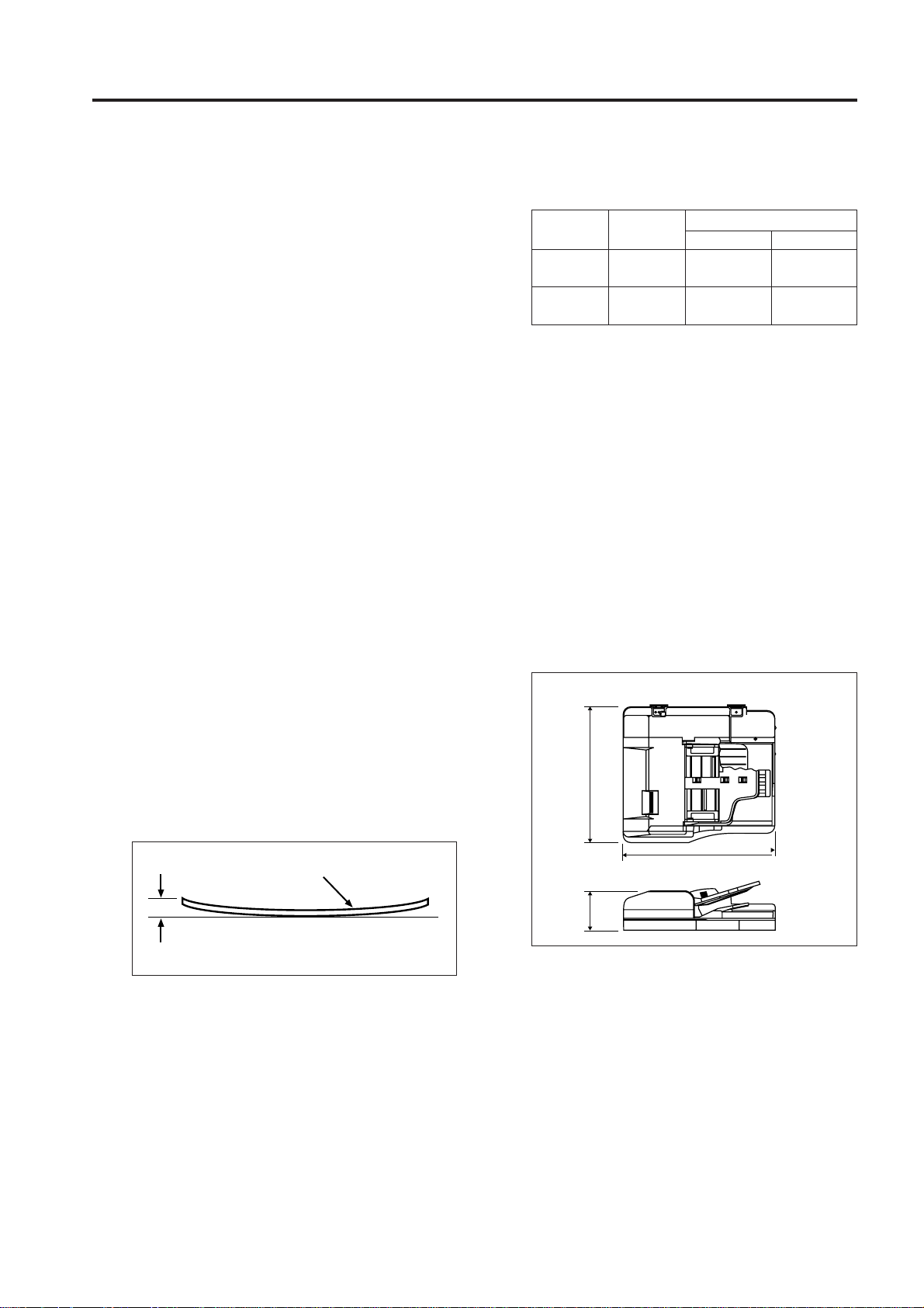
Machine dimensions:
570
1 OUTLINE
unit:mm
Original
Curling
Original curling:
10 mm maximum
Maximum number of stacked originals:
100 sheet maximum (80g/m
2
or 22 lbs)
650
170
[4] Maintenance
Maintenance: Same as the main body
Service life: Same as the main body
[5] Operating Environment
Temperature:
10°C to 30°C (50°F to 86°F)
Humidity:
10% to 80%RH
Note: The information herein may subject to change
for improvement without notice.
1 - 1
Page 8
DF-313/DF-317
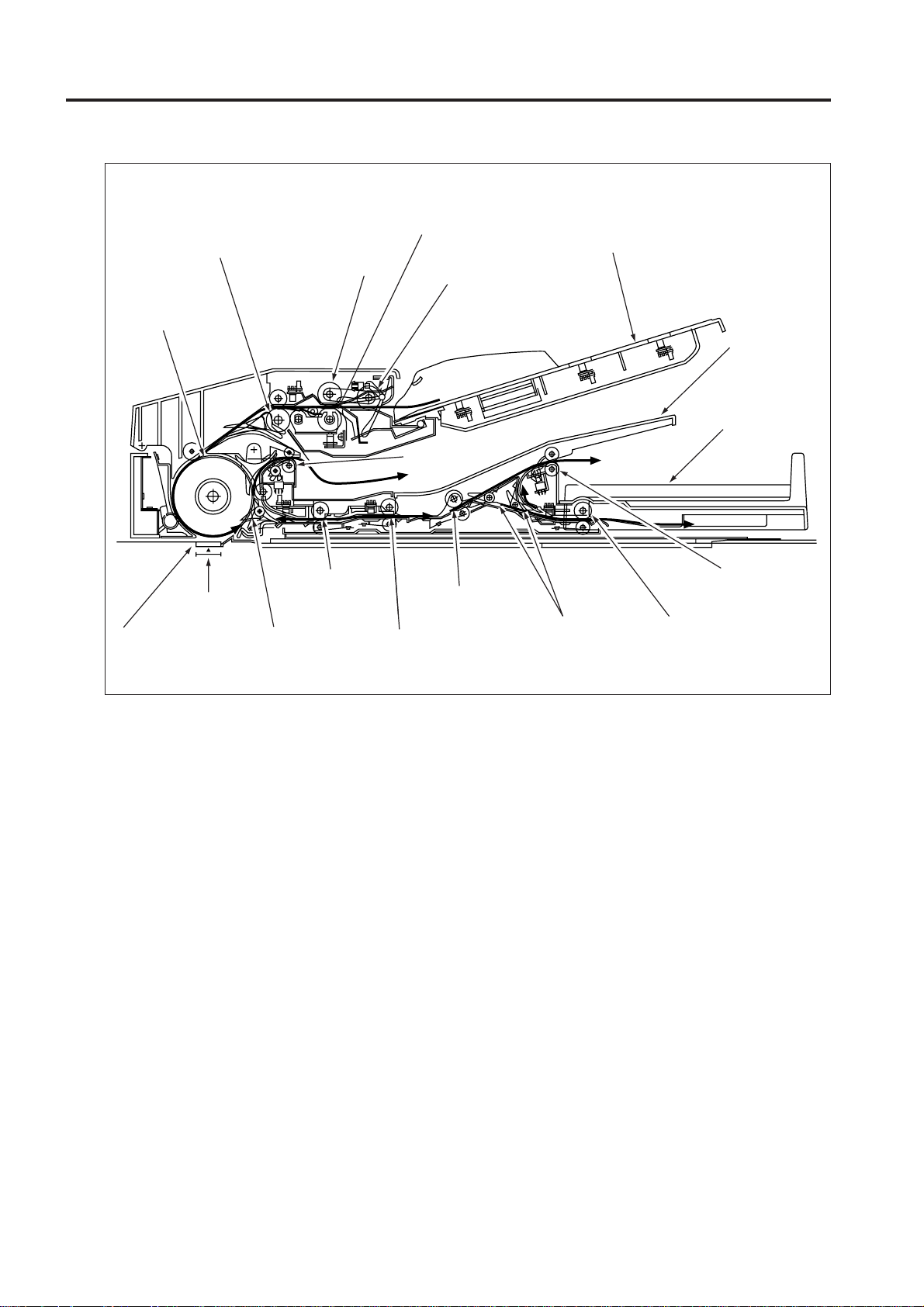
CENTER CROSS-SECTIONAL DRAWING
1 OUTLINE
Double feed
prevention roller
Registration roller
Separation roller
Original
conveyance
roller
Original feed roller
Original exit
roller 1
Original feed tray
Original exit
tray (for largesize original)
Original exit
section (for smallsize original)
Slit glass
Read position
Flapper
Reversal roller
Reversal
conveyance roller 2
Reversal conveyance roller 1
Original exit gate
Original exit
roller 2
Original exit reversal
roller
1 - 2
Page 9
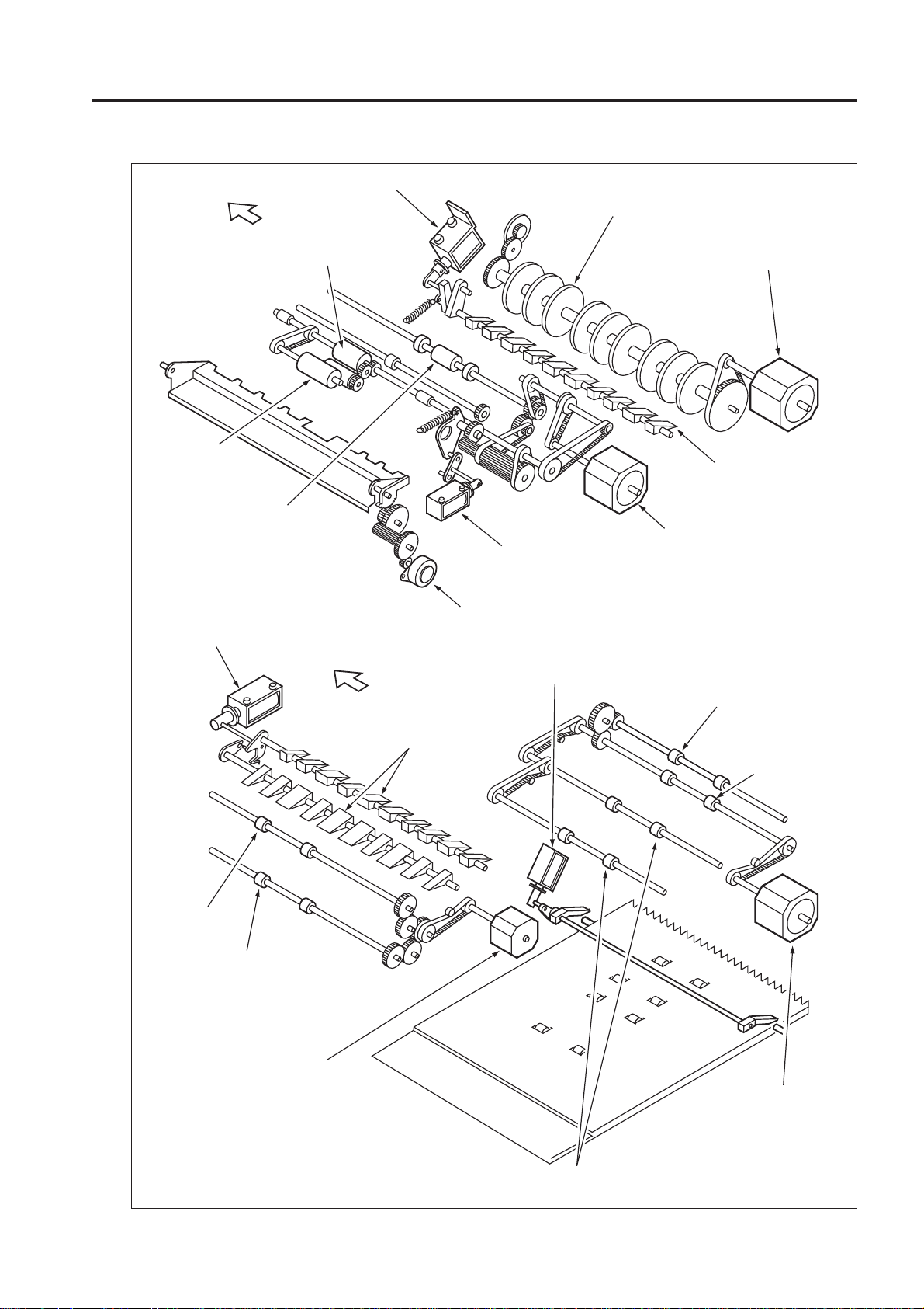
DRIVE SYSTEM DIAGRAM
DF-313/DF-317
FRONT
Original
feed roller
Registration roller
Original exit gate SD
(SD303)
Flapper drive
SD (SD 301)
Separation roller
Original conveyance roller
SDF switching SD
(SD304)
Tray up/down drive
motor (M303)
1 OUTLINE
Original conveyance motor
(M301)
Flapper
Original feed motor
(M302)
Original exit
roller 2
Original exit motor 2
(M305)
Original exit reversal
roller
Pressure roller release SD (SD302)
FRONT
Original exit gate
Original exit roller 1
Reversal roller
Original exit motor 1
(M304)
1 - 3
Reversal conveyance roller
Page 10
DF-313/DF-317
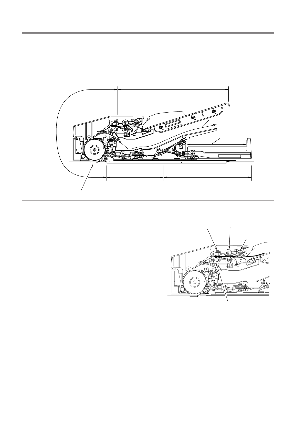
ORIGINAL CONVEYANCE PROCESS
1 OUTLINE
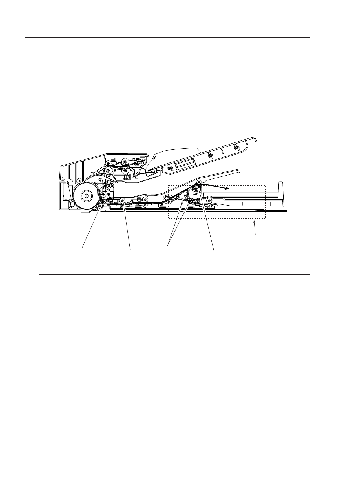
The DF-313/DF-317 consists of a original feed section, conveyance section, reversal section, original exit reversal
section, original exit tray (large), and original exit tray (small).
Original conveyance
section
Original reversal
section
Slit glass (Read section)
The original placed faced up on the original feed tray
is fed from the topmost original. The fed original is not
conveyed to the original glass. Instead, it is read when
it passes the slit glass placed in the conveyance path.
Original feed section
Original registration
detection PS (PS306)
Original exit tray
Original exit tray (small)
Original exit reversal
section
Separation roller
Original feed
roller
The DF-313/DF-317 operation consists of (a) single
side original copy mode, (b) double side original copy
mode, (c) mixed original copy mode and Z fold mode.
Each has a different conveyance path. The conveyance path also depends on the original size.
[1] Single side original copy mode
(large)
(single side to single side copy, single side to
double side copy)
The original set in the original feed tray is fed by
the original feed roller and separation roller until
PS306 (original registration detection) turns on.
Registration roller
1 - 4
Page 11

DF-313/DF-317
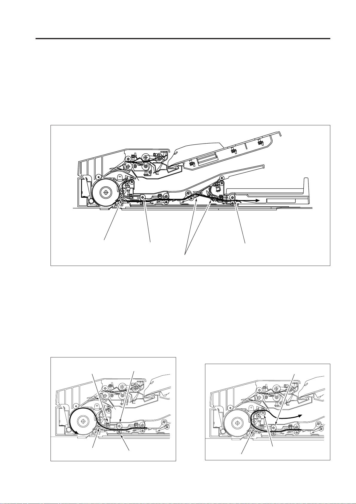
When PS306 turns on, the registration roller prefeeds the original and original is rapidly conveyed
to the conveyance roller. The speed of the
conveyance roller changes to scan speed at
predefined interval after PS306 turns ON and
feeds the original over the slit glass.
At this point, if the next original is present, it is
pre-fed as soon as PS306 detects its leading
edge.
Original conveyance
detection PS (PS308)
Registration roller
1 OUTLINE
Slit glass
Slit glass
Original conveyance roller
Next original
Original exit roller 1
Flapper
The original is read when it passes over the slit
glass. The original that has been read is
conveyed along the circumference of the
conveyance roller by the opening of the flapper,
goes through original exit roller 1, and is exited
to the original exit tray (large).
1 - 5
Page 12
DF-313/DF-317
1 OUTLINE
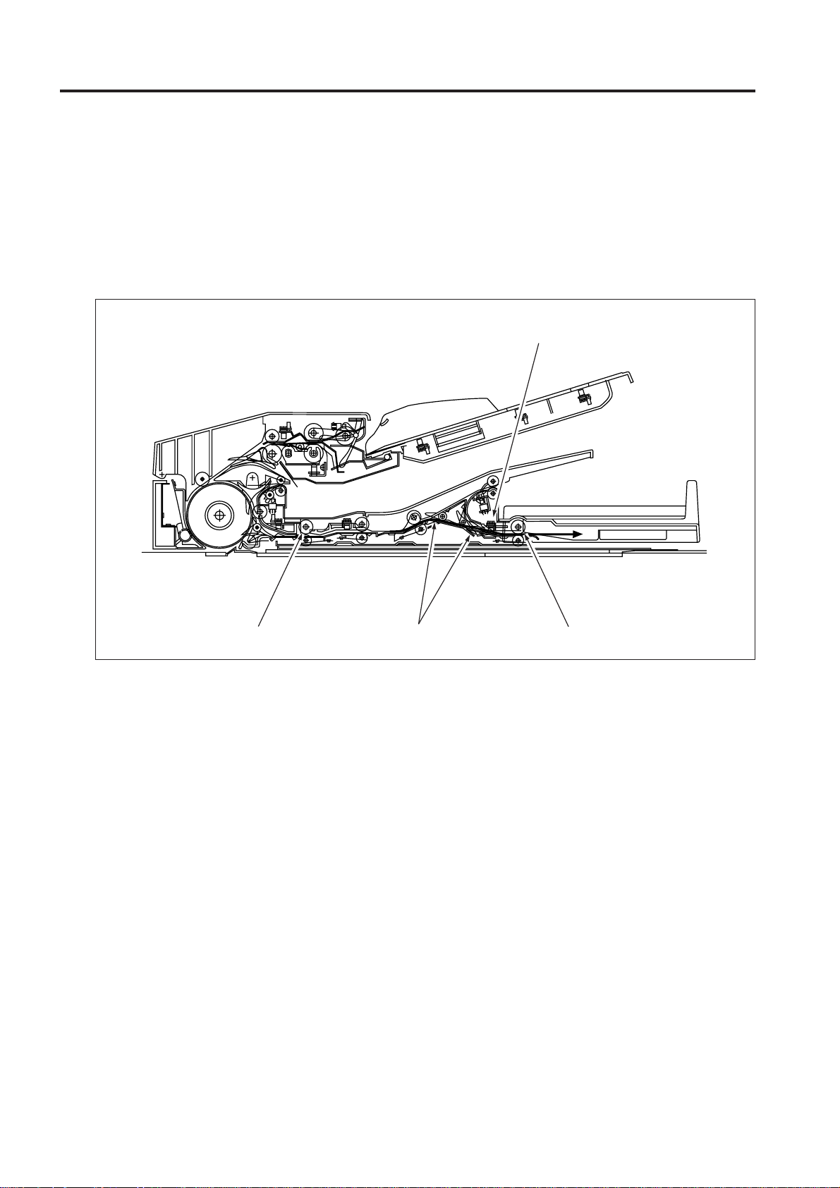
[2] Single side original copy mode (small)
(single side to single side copy, single side to double side copy)
The original feed and conveyance actions up to scanning are performed in the same manner as for single
side original copy mode (large). The original that has been scanned is fed to the original reversal unit by the
reversal roller because the flapper is closed and the paper exit path is blocked. The original fed to the
reversal unit passes through the original exit roller 2 and is exited to the original exit tray (small) since the
original exit gate is closed.
Flapper
Reversal roller
Original reversal
section
Original exit gate
Original exit roller 2
1 - 6
Page 13
DF-313/DF-317
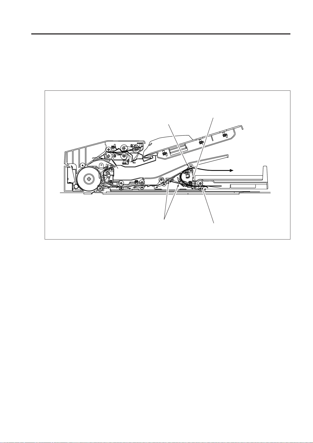
[3] Double side original copy mode (large)
(double side to single side copy, double side to double side copy)
The original conveyance action up to the start of scanning of the front side of the first double side original is
the same as for single side original copy mode (large). The original that has been scanned and read on the
front side is fed by the reversal roller to the reversal unit since the flapper is closed and the original exit path
is blocked. The original fed to the reversal unit does not fit in the reversal unit so the original exit gate opens
to feed it to the original exit reversal section.
1 OUTLINE
Flapper
Reversal roller
Original exit gate
When the original reversal detection PS (PS309)
detects the trailing edge of the original and turns off,
the reversal roller changes direction and feeds the
original in the reversal section to the conveyance roller.
Since the original is passed over the surface of the
flapper, it is sent to the conveyance roller with sides
reversed. The original reaching the conveyance roller
does not exit the reversal roller so the pressure roller
is released. The conveyance roller feeds this original
over the slit glass for scanning.
Original reversal
detection PS (PS309)
Reversal roller
Original exit reversal roller
The original that has completed scanning of the
back side is fed inside the reversal unit once again
since the flapper is closed. When PS309 detects
the trailing edge of the original and turns off, the
reversal roller changes direction and feeds the
original in the reversal unit to the conveyance
roller. Since the flapper is now opened, the
original is fed along the flapper, passes through
original exit roller 1, and is exited to the original
exit tray (large).
Reversal roller
Flapper
Pressure roller
1 - 7
Flapper
Original exit roller 1
Page 14
DF-313/DF-317
1 OUTLINE
[4] Double side original copy mode (small)
(double side to single side copy, double side to double side copy)
The original conveyance action up to the start of scanning of the back side is the same as double side
original copy mode (large). The original that has been scanned and read on the back side is fed by the
reversal roller to the reversal section since the flapper is closed and the original exit path is blocked. Then
the original exit gate opens and the original is fed to the original exit reversal section.
Original exit reverse detection PS
(PS313)
Reversal roller
Original exit gate
Original exit reversal roller
1 - 8
Page 15
DF-313/DF-317
When PS313 (original exit reverse detection) detects the trailing edge of the original and turns off, the
original exit reversal roller changes direction and feeds the original to the original exit gate. Since the
original exit gate is closed, the original passes over the original exit gate and is exited from the original exit
roller 2 to the original exit section (small) with sides reversed.
Original exit reverse detection PS
(PS313)
Original exit roller 2
1 OUTLINE
Original exit gate
Original exit reversal roller
[5] Mixed original copy mode
The mixed original copy mode supports both the same series originals and different series originals. However,
since the size of the original in the conveyance direction is determined by the ON interval of PS306, size
detection is performed prior to scanning.
The subsequent operations are the same as other copy modes.
For details on size detection, refer to section [6] Original Size Detection Control in section 2. UNIT EXPLANATION.
1 - 9
Page 16

DF-313/DF-317
1 OUTLINE
Blank page
1 - 10
Page 17

2
UNIT EXPLANATION
2 UNIT EXPLANATION
Page 18

2 UNIT EXPLANATION
Blank page
Page 19
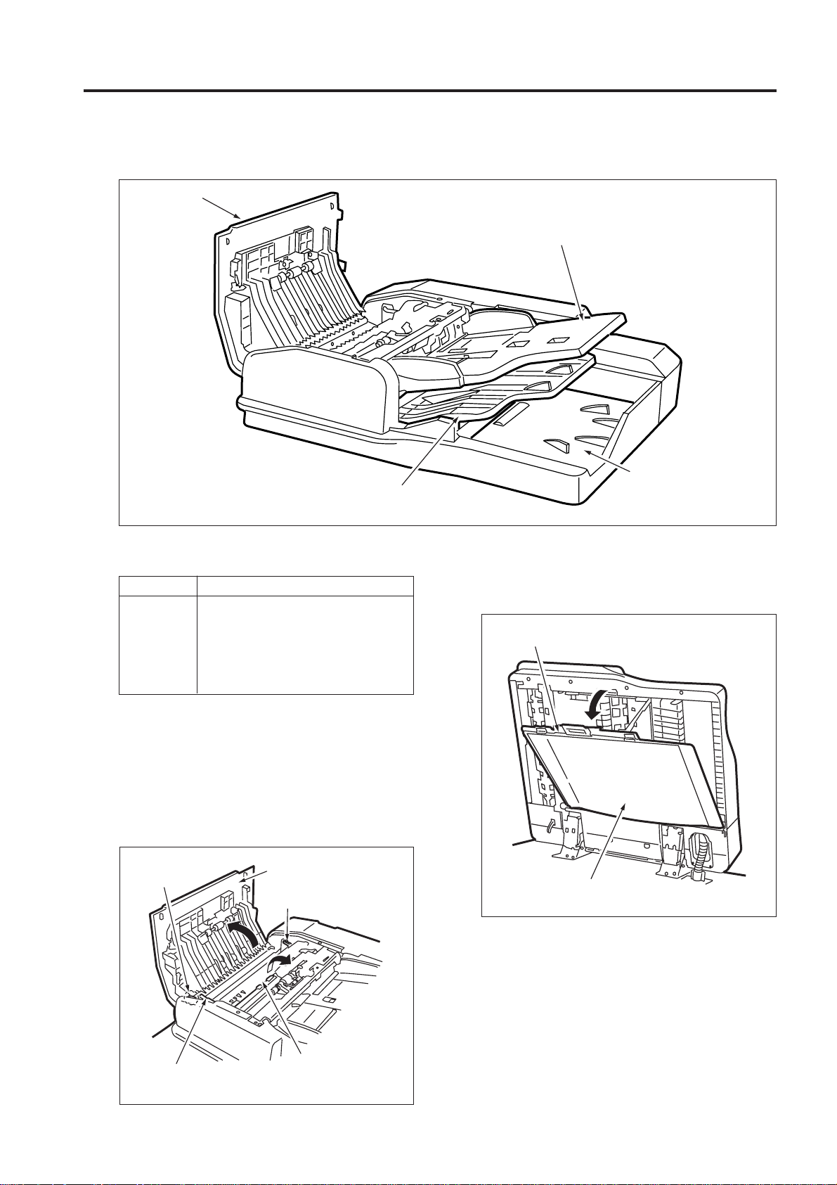
EXTERNAL SECTION
[1] Composition
Jam access
cover
Original exit tray (for large-size original)
DF-313/DF-317
Original feed tray
2 UNIT EXPLANATION
Original exit section
(for small-size original)
[2] Mechanisms
Mechanism
*1
Jam removal
Jam access cover
Jammed original release knob
Original conveyance guide open/
close lever
Platen guide
*1 Jam removal
If an original jam occurs during original feed, open
the Jam access cover and the original conveyance
guide by releasing the original conveyance guide
open/close lever, then turn the jammed original
release knob to remove the jammed original.
Jammed original
release knob
System
Jam access cover
Original conveyance
guide open/close lever
If an original jam occurs during original reversal
operation, open the platen guide to remove the
jammed original .
Lock
Platen guide
Original conveyance
guide open/close lever
Original conveyance
guide
2 - 1
Page 20

DF-313/DF-317
If an original jam occurs during original exit, open
the original feed tray and original exit tray (for
large-size original) to remove the jammed
original.
2 UNIT EXPLANATION
Original feed
tray
Original exit tray
(for large-size original)
2 - 2
Page 21
DF-313/DF-317
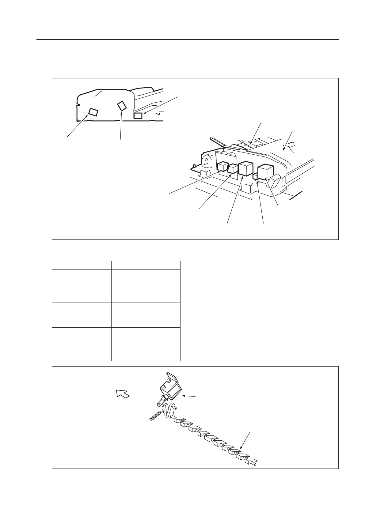
ORIGINAL FEED/CONVEYANCE/EXIT SECTION
[1] Composition
Original exit gate solenoid
(SD303)
Original feed tray
Jam access cover
Flapper drive
solenoid
(SD301)
Pressure roller release solenoid
(SD302)
Original exit motor 2
(M305)
Original exit motor 1
(M304)
[2] Mechanisms
Mechanism System
Original feed Original feed roller
Double feed Double feed prevention
prevention roller
Separation roller
Original conveyance
*1 Original conveyance Flapper
path selection
*2 Original reverse and Reversal roller pressure
feed Reversal roller rotation
*3 Original exit Gate 1
path selection Gate 2
Original conveyance roller
Original conveyance
motor (M301)
Original feed motor
(M302)
SDF switching solenoid
(SD304)
*1 Original conveyance path selection
In the two-sided copy mode, the original
conveyance path selected after completion of
scanning differs depending on whether the image
on the front surface is to be printed or the image
on the back surface is to be printed. A flapper is
used to switch between these original
conveyance paths. The flapper drive solenoid
(SD301) is turned ON/OFF to switch between the
reversal section and the original exit section.
2 UNIT EXPLANATION
FRONT
SD301
(Flapper drive SD)
Flapper
2 - 3
Page 22
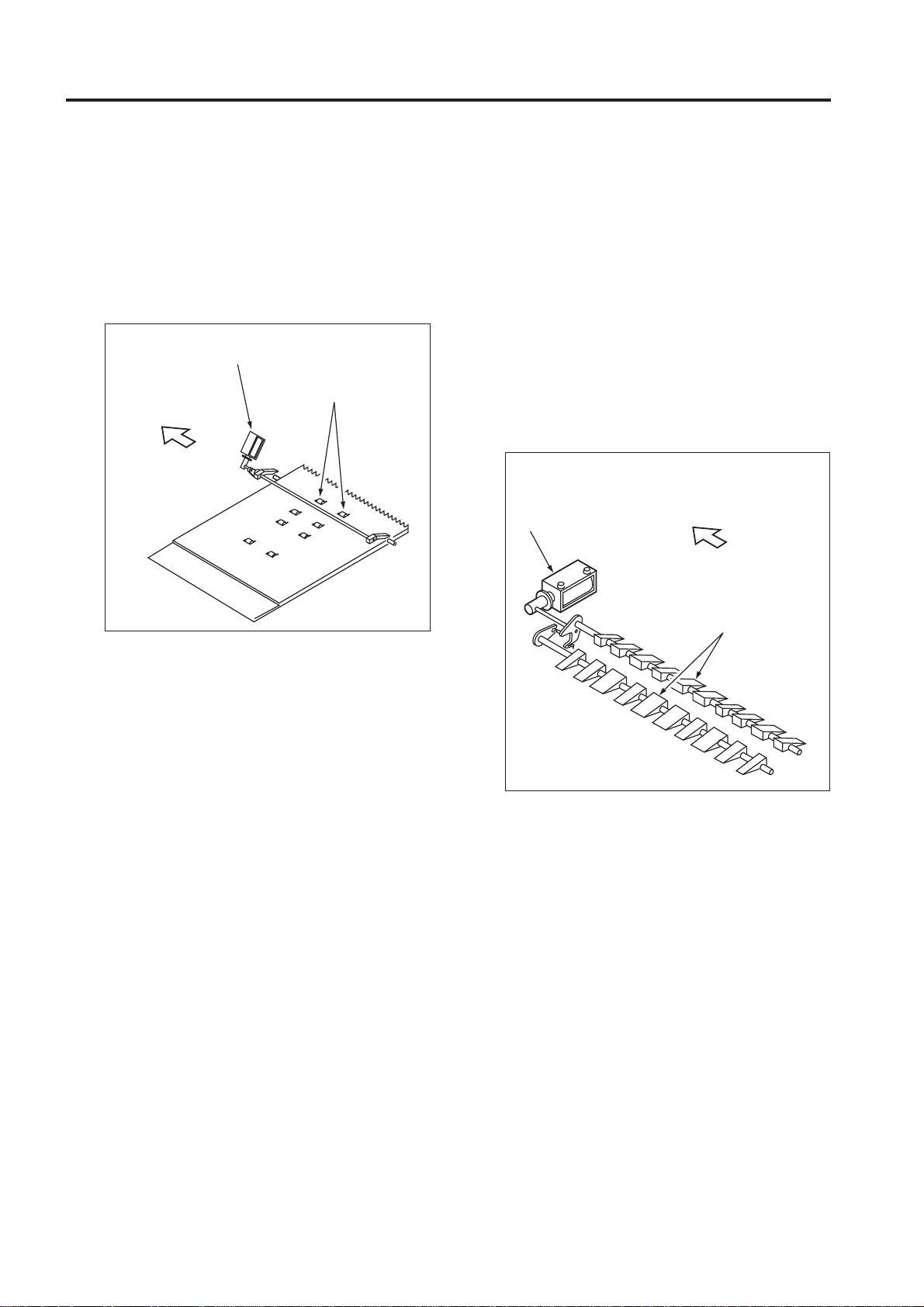
DF-313/DF-317
*2 Reversed original feed
In the double-side copy mode, the original fed to
the reversal section is fed back by pressing the
the pressure roller against the reversal roller.
The pressure roller is driven by the pressure roller
release solenoid (SD302).
Pressure roller release
solenoid (SD302)
2 UNIT EXPLANATION
FRONT
Pressure roller
*3 Original exit path switching
Large-size one-side and two-side originals are
exited to the original exit tray (for large-size
original). On the other hand, small-size one-side
and two-side originals are exited to the original
exit section (for small-size original) through the
reversal section. The small-size two-side original
fed to the reversal section is reversed and exited
to the small size original exit section. The original
exit path switching to which the original is exited
is performed by the gate 1 and gate 2, driven by
the ON/OFF contol of the original exit gate
solenoid (SD303).
Original exit gate
solenoid (SD303)
FRONT
Original exit gate
2 - 4
Page 23
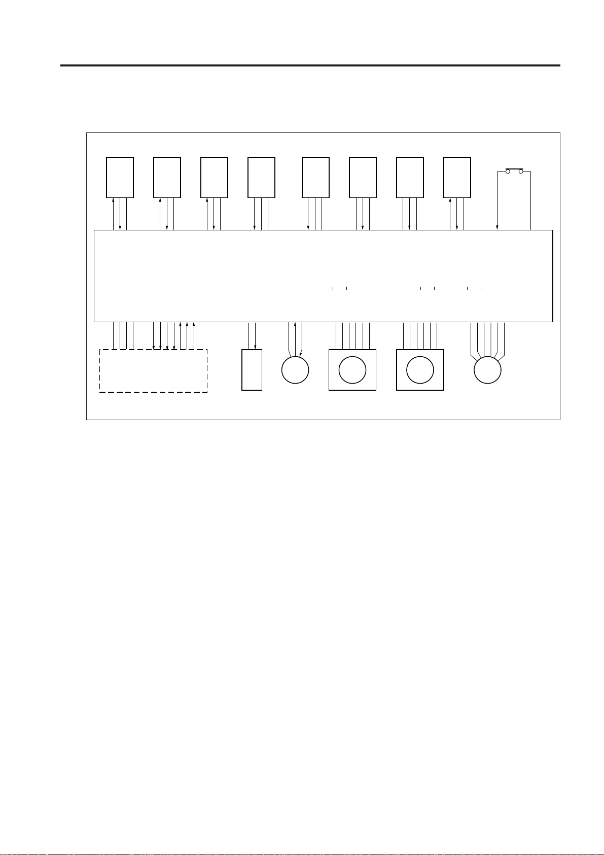
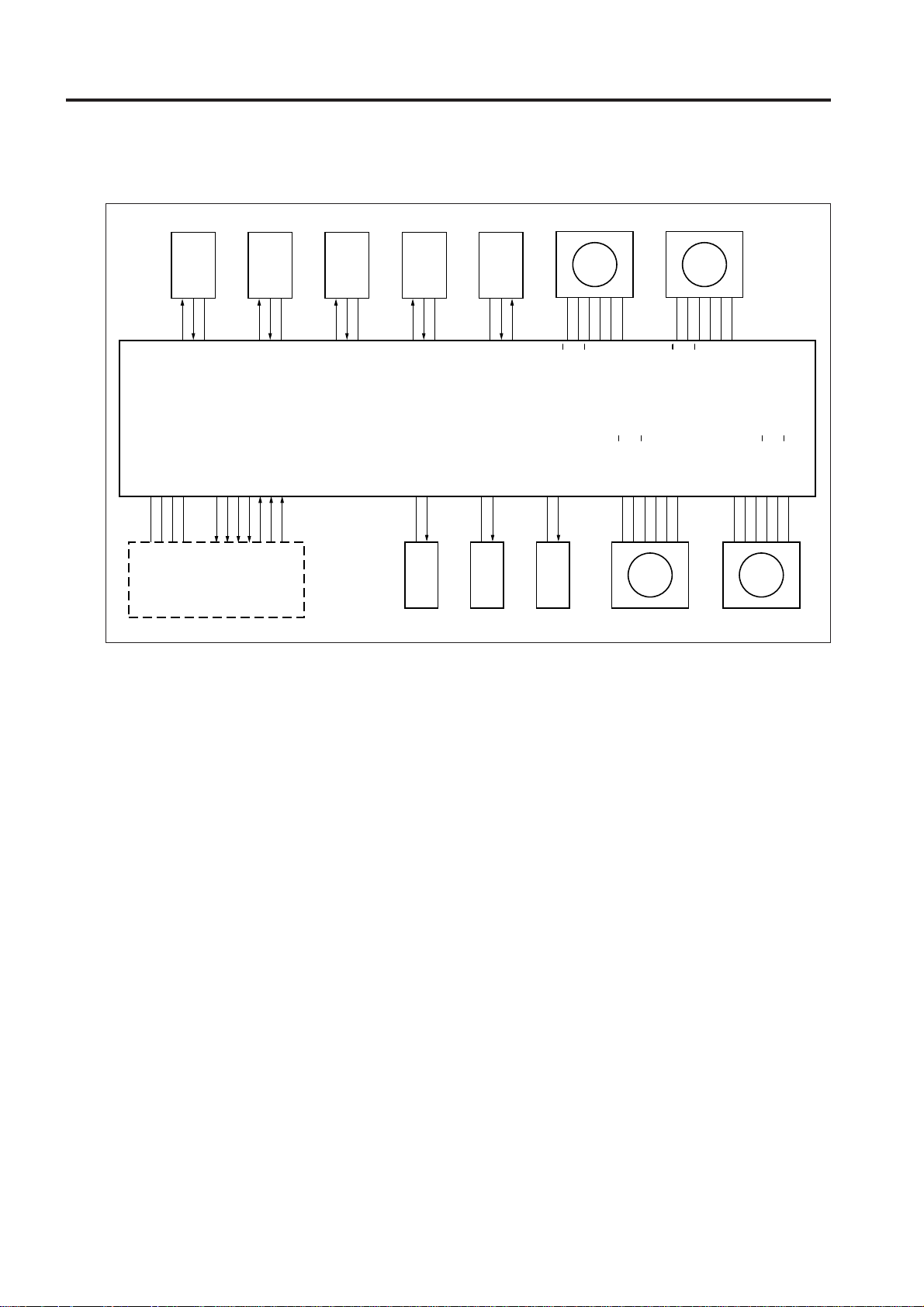
[3] Original Feed/Conveyance/Scan Control
PS312 PS311 PS308 PS301 PS316 PS315 PS305 PS306
DF-313/DF-317
MS301
5VDC
PS312
PS312 LED CONT
5VDC
SGND
PGND
24VDC
MAIN BODY
PS311
PS311 LED CONT
DF VALID
DF CTS
DF DTR
5VDC
DF RXD
DF RTS
DF DSR
PS308
PS308 LED CONT
DF TXD
5VDC
PS301
24VDC
SD304 DRIVE
SD304
5VDC
SGND
PGND
FM301 LD
FM301 M302 M301 M303
Original feed is performed by the original feed roller and
separation roller driven by M302 (original feed). Original
conveyance is performed by the original conveyance roller
driven by M301 (original conveyance).
M301 and M302 are controlled by DFCB (RADF control board).
1. Operation
a. Sensor activation at power ON
When SW1 (main) is ON, a sensitivity adjustment
for PS306 (original registration detection), PS308
(original conveyance detection), PS311 (original
skew detection 1) and PS312 (original skew detection 2) are performed. However, automatic
adjustment is not performed when the RADF jam
access cover is opened and MS301 (cover open/
close MS) is OFF or when there is original inside
the RADF.
b. Pressing original against roller
(1) First original
When a control signal is received from the main
body, M303 (tray up/down drive) turns forward
to raise the original feed tray. By this moment,
5VDC
SGND
PS316
DFCB
FM301 DRIVE
5VDC
PS315
M302 DRIVE B
M302 DRIVE B
M302 DRIVE A
M302 DRIVE A
24VDC
SGND
24VDC
5VDC
PS305
24VDC
24VDC
SGND
M301 DRIVE A
M301 DRIVE A
M301 DRIVE B
M301 DRIVE B
the original is raised and pressed against the
original feed roller.
After PS315 (tray upper limit detection) turns ON,
M303 stops after a predefined interval and leaves
the original feed tray raised in standby state.
After M302 feeds the first original, M303 rotates
backward after a predefined time has elapsed
since it stopped, lowering the original feed tray,
and the pressure on the originals is released.
M303 continues to rotate backward for a
predefined interval and then stops and remains
in standby state. At this point the original feed
tray waits without lowering to the bottom.
(2) Second and subsequent originals
When PS308 (original conveyance detection)
detects the leading edge of the first original and
turns ON, M303 that was in standby turns forward
to raise the original feed tray and presses the
original against the original feed roller.
Subsequent operations are the same as for the
first original.
5VDC
PS306
PS306 LED CONT
M303 DRIVE B
M303 DRIVE B
M303 DRIVE A
M303 DRIVE A
MS301
24VDC
24VDC
24VDC
2 UNIT EXPLANATION
2 - 5
Page 24

DF-313/DF-317
c. Original feed
M302 drives the original feed roller and separation roller.
When a control signal from the main body is received, M302 rotates forward at low speed, stops,
and goes into standby.
When the original feed tray is raised and PS315
turns ON, M302 turns backward after a predefined
interval to start original feed operation. Then,
when PS306 (original registration detection)
detects the leading edge of the original and turns
ON, M302 switches to high speed forward after a
2 UNIT EXPLANATION
predefined interval to complete the original feed
operation. After completing original feed at high
speed forward, M302 returns to low speed forward
and stops and goes into standby when PS308
(original conveyance detection) turns ON.
d. Original conveyance operation
When feeding the first original, M302 transports
the original to the conveyance roller by continuing
to rotate at high and low speed.
During this time, M301 (original conveyance)
starts rotating forward at low speed at predefined
time after PS306 turns ON. The original reached
to the conveyance roller is then conveyed to the
scan position.
After starting conveyance of the first original,
M301 continues to rotate forward at low speed
until the last original is scanned.
e. Scan operation
The original is passed over the slit glass of the
optics unit by the low speed forward rotation of
M301 and read (scanned). While the original is
being scanned, original feed and conveyance operations continue, triggered by the turning ON of
PS308.
f. Original mis-centering detection control
PS311 (original skew detection 1) and PS312
(original skew detection 2) are provided to detect the inclined leading edge of the original during conveyance.
PS311 and PS312 are placed at the front and
back of the pre-scan conveyance path and determine the inclination of the original by
measuring the difference in interval at which the
leading edge of the original turns these switches
ON. A skewed image caused by original
inclination is corrected through image processing
so that the image on the original is copied to a
copy paper as it is on the original.
g. SDF (Single Document Feeder) control
When SDF mode is selected, SD304 (SDF
switching SD) cut the drive force to the double
feed prevention roller to facilitate original feeding.
(1) ON timing
At the start of original feed
(2) OFF timing
When PS306 turns OFF
h. FM301 (ADF fan) operation
FM301 is used to cool M301 so that M301 does
not overheat during operation.
(1) ON timing
At the start of original feed
(2) OFF timing
When original ejection completed.
i. Jammed original ejection control
Upon receiving a control signal from the main
body, M301 rotates at high speed forward,
attempting to eject a jammed original in the
RADF.
2. Signals
a. Input signal
(1) MS301 (MS301 to DFCB)
Jam access cover open/close detection signal.
[L] : Cover opened
[H] : Cover closed
(2) PS301 (PS301 to DFCB)
RADF open/close detection signal.
[L] : RADF closed
[H] : RADF opened
(3) PS305 (PS305 to DFCB)
No original on original feed tray detection signal.
[L] : Original present
[H] : No original
(4) PS306 (PS306 to DFCB)
Original feed over original conveyance roller
detection signal.
[L] : Original present
[H] : No original
(5) PS308 (PS308 to DFCB)
Pre-scan position original detection signal.
[L] : Original present
[H] : No original
2 - 6
Page 25

DF-313/DF-317
(6) PS311 (PS311 to DFCB)
Front side original skew detection signal.
[L] : Original present
[H] : No original
(7) PS312 (PS312 to DFCB)
Rear side original skew detection signal.
[L] : Original present
[H] : No original
(8) PS315 (PS315 to DFCB)
Original feed tray upper limit detection signal.
[L] : Tray at upper limit
[H] : Tray not at upper limit
(9) PS316 (PS316 to DFCB)
Original feed tray lower limit detection signal.
[L] : Tray at lower limit
[H] : Tray not at lower limit
(10) FM301 LD (FM301 to DFCB)
Goes [L] when FM301 reaches predefined speed.
(11) DF TXD (MAIN BODY to DFCB)
Serial data for transmitting main body PRCB
operating status to RADF.
(12) DF RTS (MAIN BODY to DFCB)
Send the Request To Send signal from main body
PRCB to RADF.
(13) DF DSR (MAIN BODY to DFCB)
Send the Data Set Ready signal from main body
PRCB to RADF.
b. Output signals
(1) PS306 LED CONT (DFCB to PS306)
Reflective sensor PS306 LED ON/OFF control
signal.
[L] : PS306 LED ON
[H] : PS306 LED OFF
(2) PS308 LED CONT (DFCB to PS308)
Reflective sensor PS308 LED ON/OFF control
signal.
[L] : PS308 LED ON
[H] : PS308 LED OFF
(3) PS311 LED CONT (DFCB to PS311)
Reflective sensor PS311 LED ON/OFF control
signal.
[L] : PS311 LED ON
[H] : PS311 LED OFF
(4) PS312 LED CONT (DFCB to PS312)
Reflective sensor PS312 LED ON/OFF control
signal.
[L] : PS312 LED ON
[H] : PS312 LED OFF
(5) M301 DRIVE A, A (DFCB to M301)
M301 A phase drive signal.
(6) M301 DRIVE B, B (DFCB to M301)
M301 B phase drive signal.
(7) M302 DRIVE A, A (DFCB to M302)
M302 A phase drive signal.
(8) M302 DRIVE B, B (DFCB to M302)
M302 B phase drive signal.
(9) M303 DRIVE A, A (DFCB to M303)
M303 A phase drive signal.
(10) M303 DRIVE B, B (DFCB to M303)
M303 B phase drive signal.
(11) FM301 DRIVE (DFCB to FM301)
FM301 ON/OFF drive signal.
[L] : FM301 ON
[H] : FM301 OFF
(12) DF TXD (DFCB to MAIN BODY)
Serial data for transmitting RADF operating status to main body PRCB.
(13) DF DTR (DFCB to MAIN BODY)
Send the Data Terminal Ready signal from RADF
to main
(14) DF CTS (DFCB to MAIN BODY)
Send the Clear To Send signal from RADF to main
body
(15) DF VALID (DFCB to MAIN BODY)
Image forming start signal.
body
PRCB.
PRCB.
2 UNIT EXPLANATION
2 - 7
Page 26
DF-313/DF-317
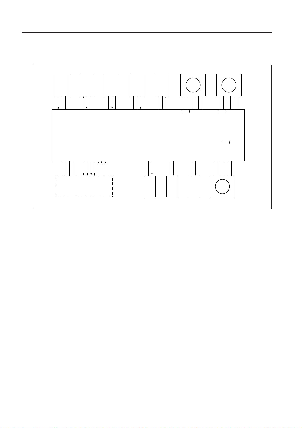
[4] Original Reversal and Conveyance Control
PS308 PS309 PS304 PS306
5VDC
PS309
PS309 LED CONT
DF DTR
DF RXD
DF RTS
DF TXD
DF DSR
PS304 LED CONT
2 UNIT EXPLANATION
5VDC
SGND
24VDC
5VDC
PS308
PS308 LED CONT
DF VALID
DF CTS
PGND
MAIN BODY
In two side copy mode, an original that has been
scanned on the front side is conveyed to the original
reversal section to be reversed and then rescanned.
At entrance to the original reversal section, there is a
flapper to switch the original conveyance path. The
flapper is driven by SD301 (flapper drive). The reversal
roller, which reverses and conveys front-side-scanned
original to the original reversal section and feeds that
original to the scan section again, is driven by M304
(original exit 1). The original reversal roller which
conveys original to the original reversal section is driven
by M305 (original exit 2). When reversing and feeding
large originals, the pressure roller is released by SD302
(pressure roller release).
M304, M305, SD301, and SD302 are controlled by
DFCB (RADF control board).
1. Operation
a. Sensor activation during power ON
When SW1 (main) is turned ON, a sensitivity
adjustment for PS309 (original reversal detection)
and PS313 (original exit reverse detection) are
performed. However, automatic adjustment is
not performed when the RADF jam access cover
5VDC
PS304
PS313
5VDC
PS306
PS306 LED CONT
24VDC
SD301 DRIVE
SD301 SD302 SD303
DFCB
5VDC
PS313
PS313 LED CONT
24VDC
SD302 DRIVE
24VDC
is opened and MS301 (cover open/close MS) is
OFF or when there is original inside the RADF.
b. Original conveyance path switching/
reversal and original feed operation
(1) Small size original
SD301 is always OFF and the flapper is closed.
Therefore, the scanned original, whether it is
single side or double side, is conveyed to the
reversal section by M304 rotating at low speed
forward.
When copying the back side of a double-side
original, at predefined interval after PS309
(original reversal detection) detects the trailing
edge of original and turns OFF, M304 rotates
backward at low speed and then at high speed
to reverse and feed the original. The reversed
original is conveyed through the flapper and the
guides to the conveyance roller.
(2) Large size original
The scanned-single side original is conveyed to
the original exit tray (large) by the original
conveyance roller since SD301 is ON and the
flapper is opened.
M305 DRIVE A
M305 DRIVE A
M305 DRIVE B
M305 DRIVE B
SD303 DRIVE
M304M305
24VDC
24VDC
M304 DRIVE A
M304 DRIVE A
M304 DRIVE B
M304 DRIVE B
M302 DRIVE B
M302 DRIVE B
M302 DRIVE A
M302 DRIVE A
24VDC
24VDC
M302 M301
24VDC
24VDC
24VDC
24VDC
M301 DRIVE A
M301 DRIVE A
M301 DRIVE B
M301 DRIVE B
2 - 8
Page 27

DF-313/DF-317
In the case of large double-side original, the original is conveyed to the reversal section when
SD301 turns OFF after scanning the front side
of a double-side original . The original reaching
the reversal section does not fit in the reversal
section so it is fed to the large-size original exit
tray side by the large original reversal roller,
which is driven by M305 (original exit 2). During
this time, SD303 (original exit gate) turns ON and
the original exit gate is closed.
The original conveyed to the reversal section is
reversed and fed to the scan section again in the
same manner as small originals. Since the
original reaching the conveyance roller does not
exit the reversal roller, SD302 is turned ON at
predefined interval after high speed backward
rotation of M304 to release the pressure roller
for the reversal roller. This enables original
conveyance using the conveyance roller. SD302
turns OFF when it detects an image scan
complete signal from the main unit.
c. Two side original next original feed
operation
(1) Small size original
During front-side scanning of two-side original,
the original feed of the next one is started by the
rotation of M302 (original feed) when PS306
(original registration detection) detects the trailing edge of the previous original and turns OFF.
The next original stops and waits in standby at
predefined interval after the turning ON of PS306
by its own leading edge.
When the back side of the first original is scanned
and PS308 (original conveyance detection) turns
ON, M302 turns ON after a predefined interval
to resume original feed to scan the front side of
the next original. Thereafter, the same operation is repeated.
(2) Large size original
During front-side scanning of double-side original, the original feed of the next original is started
when PS306 (original registration detection) detects the trailing edge of the previous original and
turns OFF. The next original stops and waits in
standby at predefined interval after the turning
ON of PS306 by its own leading edge.
During ejection of previous original by reverse
and exit operation, when PS309 (original reversal
detection) detects the trailing edge of the previous original and turns OFF, M302 turns ON after
a predefined interval to resume original feeding
to scan the front side of the next original. Thereafter, the same operation is repeated.
Note: See [5] Original Exit Control for informa-
tion on reverse and exit operation.
d. Jammed original ejction control
Upon receiving a control signal from the main
unit, M304 and M305 rotate at high speed
forward, attempting to eject a jammed original in
the RADF.
2 UNIT EXPLANATION
2. Signals
a. Input signals
(1) PS304 (PS304 to DFCB)
Reversal section original detection signal.
[L] : Original present
[H] : No original
(2) PS309 (PS309 to DFCB)
Reversal section entrance original detection
signal.
[L] : Original present
[H] : No original
(3) PS313 (PS313 to DFCB)
Original ejection reversal section original detection signal.
[L] : Original present
[H] : No original
b. Output signals
(1) M304 DRIVE A, A (DFCB to M304)
M304 A phase drive signal.
(2) M304 DRIVE B, B (DFCB to M304)
M304 B phase drive signal.
(3) M305 DRIVE A, A (DFCB to M305)
M305 A phase drive signal.
(4) M305 DRIVE B, B (DFCB to M305)
M305 B phase drive signal.
2 - 9
Page 28
DF-313/DF-317
[5] Original Exit Control
PS307 PS309 PS304
5VDC
SGND
PS307
2 UNIT EXPLANATION
5VDC
SGND
PGND
24VDC
MAIN BODY
The ejection destination of the original that has
been scanned depends on the size of original.
The original exit roller 1 which conveys the
original to the original exit tray (large) is driven
by M304 (original exit 1). The original exit roller
2 which conveys the original to the original exit
section (small) is driven by M305 (original exit
2). The flapper which switches the original exit
path and the original exit gate are driven by
SD301 (flapper drive) and SD303 (original exit
gate) respectively.
M304, M305, SD301, and SD303 are controlled
by DFCB (RADF control board).
1. Operation
a. Small size original exit operation
(1) Single-side original
Scanned original is conveyed to the reversal section since SD301 is OFF and the flapper is closed.
Original conveyed to the reversal section is
conveyed to the original exit gate by the reversal
roller which is driven by M304. During this time,
M304 drives the conveyance roller with low speed
forward rotation.
5VDC
PS309
PS309 LED CONT
DF VALID
DF CTS
DF DTR
DF RXD
DF RTS
DF DSR
5VDC
PS304
PS304 LED CONT
DF TXD
PS314 PS313
5VDC
SGND
DFCB
PS314
5VDC
PS313
PS313 LED CONT
24VDC
SD301 DRIVE
SD301 SD302 SD303
The original is conveyed to the original exit roller
2 since SD303 is OFF and the original exit gate
is opened. M305 drives the original exit roller 2
with low speed forward rotation and ejects the
original to the original exit section (small) with
the original surface facing down.
(2) Two-side original
A original that has been scanned on the back
side is conveyed to the original exit gate in the
same manner as single-side original. During this
time, SD303 is ON and the original exit gate is
closed. Therefore, the original is passed through
the original exit reversal roller, which is driven by
the low speed forward rotation of M305, and
conveyed to the original exit reversal section.
M305 turns OFF when PS313 ( original exit reverse detection) is turned OFF by the conveyed
original. When SD303 turns OFF and the original exit gate opens, M305 starts high speed backward rotation after a predefined interval and reverses the direction of the conveyed original.
Since the original exit gate is opened, the original is conveyed to the original exit section (small)
rather than returning to the reversal section.
24VDC
SD302 DRIVE
M305 M304
24VDC
24VDC
M305 DRIVE A
M305 DRIVE A
M305 DRIVE B
M305 DRIVE B
24VDC
SD303 DRIVE
M304 DRIVE B
24VDC
24VDC
M301
M304 DRIVE A
M304 DRIVE A
M304 DRIVE B
M301 DRIVE A
M301 DRIVE A
M301 DRIVE B
M301 DRIVE B
24VDC
24VDC
2 - 10
Page 29

As a result, the two-side original is ejected with
the front side facing down.
b. Large size original ejection operation
(1) Single-side original
The scanned original is conveyed to the original
exit roller 1 by the conveyance roller since SD301
is ON and the flapper is opened. The original
exit roller 1 is driven by the low speed forward
rotation of M304 and the original is ejected to
the original exit tray (large) with the copy surface
facing down.
(2) Two-side original
The original that has been scanned on the back
side is conveyed to the reversal section since
SD301 is OFF and the flapper is closed.
When PS309 (original reversal detection) detects
the trailing edge of conveyed original, SD301
(flapper drive SD) is turned ON and the flapper
is opened. Then, M304 (original exit 1) rotates
backward and the original is ejected to the original exit tray (large size original) since the flapper
is open.
DF-313/DF-317
2 UNIT EXPLANATION
2. Signals
a. Input signal
(1) PS307 (PS307 to DFCB)
Original exit tray (large) entrance original
detection signal.
[L] : Original present
[H] : No original
(2) PS314 (PS314 to DFCB)
Original exit section (small) entrance original
detection signal.
[L] : Original present
[H] : No original
2 - 11
Page 30
DF-313/DF-317
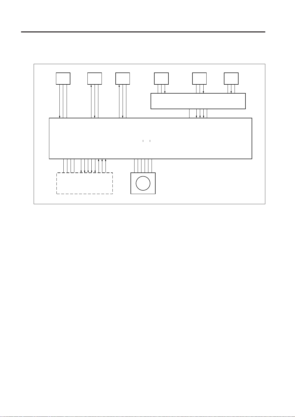
[6] Original Size Detection Control
PS317 PS308 PS306
5VDC
SGND
PS317
2 UNIT EXPLANATION
5VDC
SGND
PGND
24VDC
MAIN BODY
The size of the original placed in the original feed
tray is detected by PS302 (original size detection
1), PS303 (original size detection 2), and VR301
(original size detection).
PS302, PS303, and VR301 are controlled by
DFCB (RADF control board) through PTBD (tray
drive board). DFCB contains a non-volatile
memory for storing data such as timing data and
original size detection threshold.
1. Operation
a. Normal copy mode
DFCB detects the original size from the combination of the following signals:
(1) Drum axis direction size detection
A guide plate is connected to VR301 and the resistance vary with the position of the guide plate.
This is used to determined the vertical dimension of the original.
(2) Original feed direction size detection
The horizontal dimension of the original is detected with the ON/OFF combination of PS302
and PS303.
PS308 LED CONT
PS315
DF VALID
DF CTS
DF DTR
5VDC
PS308
DF RXD
DF RTS
DF TXD
DF DSR
5VDC
PS306
PS306 LED CONT
24VDC
24VDC
M301
PS302 PS303 VR301
5VDC
SGND
PS302
PTBD
5VDC
5VDC
SGND
PS303
PS302
PS303
SGND
VR301
5VDC
VR301
SGND
DFCB
M301 DRIVE A
M301 DRIVE A
M301 DRIVE B
M301 DRIVE B
b. Mixed copy mode original size detection
Size detection during mixed copy mode is performed as follows:
(1) Drum axis direction size detection
The vertical dimension of the largest original is
determined by the position of the guide plate.
(2) The ON interval of PS306 (original registration
detection) after the original passes the registration roller is used to determine the horizontal
dimension of each original.
2 - 12
Page 31

DF-313/DF-317
(3) Original feed direction size detection
When the original is fed, M301 (original
conveyance) turns forward and conveys the
original to the original exit tray (large). M301
continues to rotate forward until PS306 detects
the trailing edge of the original and turns OFF.
At this point, the ON interval of PS306 is used to
detect the size of original in the feed direction.
PS 306 (Original
Registration
roller
PS 308 (Original conveyance detection)
registration detection)
Original
conveyance roller
After a predefined interval since PS306 turns
OFF, M301 changes direction and returns the
leading edge of the original conveyed to the
original exit section to the scan wait position. The
trailing edge of the returned original is conveyed
to the original exit tray (large) due to the shape
of the conveyance guide plate.
The backward rotation of M301 stops at
predefined interval after PS308 (original conveyance detection) detects the leading edge of the
original and turns OFF.
Scan stanby position
Thereafter, read operation (scan) is performed
in the same manner as normal mode.
Second original
First original
The size detection of the second and subsequent
originals differ for single-side mode and two-side
mode.
• Single-side mode: After scanning of the previous original starts
• Two-side mode: When scanning of the back
side of the previous original starts
c. Allowed size combination
(❏: Same size, ❍: Same series, ▲: Different se-
ries, ✕: Mixing prohibited, —: Not supported)
Reference original (maximum-size original
detectable with guide plate)
A3 A4 B4 B5 A4R A5
A3 ❏❍——————
A4 ❍❏——————
B4 ▲▲ ❏❍————
B5 ▲▲❍❏————
A4R ▲▲▲▲ ❏❍——
A5 ▲▲▲▲❍❏——
B5R ✕✕▲▲▲▲❏ —
B6R ✕✕✕✕✕✕▲❏
2 UNIT EXPLANATION
B5R B6R
Original conveyance roller
PS 308 (Original conveyance detection)
2 - 13
Page 32

DF-313/DF-317
2. Signals
a. Input signals
(1) PS302 (PS302 to PTBD to DFCB)
Original horizontal dimension detection signal
[L] : Original present
[H] : No original
(2) PS303 (PS303 to PTBD to DFCB)
Original horizontal dimension detection signal
[L] : Original present
[H] : No original
(3) VR301 (VR301 to PTBD to DFCB)
2 UNIT EXPLANATION
Original vertical dimension detection signal
(4) PS317 (PS317 to DFCB to MAIN BODY)
Original size detection timing signal during platen
mode
Original size is detected when this signal changes
from [H] to [L].
2 - 14
Page 33

3
DISASSEMBLY/ASSEMBLY
3 DIS./ASSEMBLY
Page 34

3 DIS./ASSEMBLY
This section explains how to disassemble and reassemble the machine.
When disassembling and reassembling the machine, follow the
precautions given below.
1. Be sure the power cord has been unplugged from the wall outlet.
2. The disassembled parts must be reassembled following the
disassembly procedure in reverse unless otherwise specified.
3. Care should be taken not to lose small parts. Care should also be
taken not to install small parts in wrong places.
4. Do not operate the machine before installing all the disassembled
parts completely.
5. Removal of some screws is prohibited in this section. Never loosen
them.
Page 35

EXTERNAL SECTION
DF-313/DF-317
[1] Removing the RADF
Caution: Make sure the power cord of the
main unit has been unplugged
from the wall outlet.
a. Procedure
(1) Remove the rear cover.
(2) Remove the two screws to detach the two stop-
pers.
Screws
Stopper
(5) Remove the screw to disconnect the ground
cable.
(6) Remove the two relay connectors (CN31, CN32).
Ground
cable
Screw
Relay connector (CN32)
Relay connector (CN31)
(7) Remove the three screws to detach the cable
conduit.
3 DIS./ASSEMBLY
(3) Open the RADF to the upright position.
(4) Remove the three screws to detach the top cover
(rear) of the main unit.
Screws
Top cover (rear)
Cable conduit
Screws
3 - 1
Page 36

DF-313/DF-317
(8) Draw the cable to the top of the main unit.
(9) Close the RADF. Remove the two screws to
detach each of the two fixing plates (R).
Screws
Fixing plate (R)
(10) Open the RADF up to the upright position.
3 DIS./ASSEMBLY
(11) Holding the RADF, remove one screw to detach
each of two fixing plates.
(12) Holding the RADF, remove it from the main unit.
Caution: When the fixing plates (F) are
removed, the RADF may fall down to
the rear side. Be sure to hold the
RADF while performing steps 11 and
12.
[2] Reinstalling the RADF
Caution: Make sure the power cord of the
main unit has been unplugged
from the wall outlet.
a. Procedure
(1) Place the RADF on the top of the main unit and
loosely secure each of the two fixing plates (F)
with one screw.
Caution: The necked hole in the fixing plate (F)
must fit over the guide screw.
(2) Remove the two screws to detach the original
stopper plate (left).
Guide
screw
Screw (Tighten
temporarily)
Screws
Original
stopper plate
(left)
Necked
hole
Fixing
plate (F)
Fixing plate (F)
Screw
(3) Following the removal procedure in reverse, in-
stall the cable conduit, two relay connectors
(CN31, CN32), ground cable, and top cover (rear)
of the main unit.
(4) Install two RADF positioning jigs in the mounting
holes of the original stopper plate (left).
3 - 2
Page 37

DF-313/DF-317
(5) Close the RADF to mate the reference holes and
RADF positioning jigs.
Reference hole
(round hole)
Reference hole
(oblong hole)
RADF positioning
jigs
(6) Install two screws to secure each of the two fixing
plates (R) following the removal procedure in
reverse.
(7) Open the RADF, install the other screw for each
of the two fixing plates (F), and finaly tighten all
the four screws to secure the two fixing plates (F).
(8) Remove the RADF positioning jigs and install the
original stopper plate (left) with two screws.
(9) Close the RADF and check whether both stopper
pieces on the RADF-side touch the slit glass.
Caution: The state of contact between the
stopper pieces and the silt glass can
be checked by looking into the slits in
the top cover of the main unit.
Stopper
piece
Stopper
piece
Slit glass
Top cover
(middle)
3 DIS./ASSEMBLY
Slit
Slit
3 - 3
Page 38

DF-313/DF-317
(10) If both stopper pieces do not touch the slit glass
at the same time, make adjustments using ad-
justing screws A and B alternately.
Adjusting screw B
Adjusting screw A
(11) Perform steps (9) and (10) repeatedly until the
3 DIS./ASSEMBLY
two stopper pieces touch the slit glass at the
same time.
(12) Install the rear cover of the main unit.
3 - 4
Page 39

DF-313/DF-317
ORIGINAL FEED/CONVEYANCE/EXIT SECTION
[1] Removing/Cleaning/Reinstalling the
Original Feed Roller Unit
Caution: Make sure the power cord of the
main unit has been unplugged
from the wall outlet.
a. Procedure
(1) Open the Jam access cover.
(2) Remove the screw to detach the sensor cover.
Screw
Jam access cover
(3) Remove the spring.
(4) Remove the two stop rings to slide the bearing
and one-way clutch outward.
(5) Slide the original feed roller unit to the front to
release it from the coupling, then remove it up-
ward.
Sensor cover
(6) Clean rollers using a blower brush or the like.
(7) Reinstall the original feed roller unit in the reverse
order of the removal procedure.
Caution: Make sure the angled portion of the
original feed roller unit is positioned
above the angled portion of the stay.
If the angled portion of the original
feed roller unit is positioned below the
angled portion of the stay, originals are
not fed properly.
[2] Cleaning the Cleaning Pad
Caution: Make sure the power cord of the
main unit has been unplugged
from the wall outlet.
a. Procedure
(1) Open the movable cover.
(2) Remove one screw to detach the cleaning pad.
(3) Using a blower brush, clean the cleaning pad.
Screw
Cleaning
pad
Movable
cover
3 DIS./ASSEMBLY
Original feed
roller unit
Bearing
Stop ring
One-way clutch
Stop ring
Spring
Original feed
tray
Angled portion
Coupling
Angled portion
of original feed
roller unit
Stay
Angled
portion of
stay
Resistration
roller
(4) Reinstall the above parts following the removal
steps in reverse.
3 - 5
Page 40

DF-313/DF-317
[3] Replacing the Original Feed Roller/
Separation Roller/Auxiliary
Separation Roller
Caution: Make sure the power cord of the
main unit has been unplugged
from the wall outlet.
a. Procedure
(1) Remove the original feed roller unit.
(2) Remove the one-way clutch.
(3) Remove stop ring (1) to detach gear (1) and belt.
(4) Remove stop ring (2) and pull out shaft (1) to
detach the original feed roller.
(5) Pull the pin for gear (1) and the spacer from shaft
(2).
(6) Remove stop rings (3), (4), and (5) to pull the pin
for gear (2) from shaft (2).
(7) Pull out shaft (2) to detach the separation roller.
(8) Remove stop ring (6) to pull the pin for gear (3)
from shaft (3).
3 DIS./ASSEMBLY
3 - 6
Page 41

(9) Pull out shaft (3) to detach the auxiliary separation roller.
DF-313/DF-317
Original feed roller
Auxiliary separation roller
Stop ring (3)
Belt
Gear (3) (with a pin)
Shaft (1)
Stop ring (2)
Stop ring (6)
Shaft (3)
3 DIS./ASSEMBLY
Shaft (2)
Stop ring (5)
Gear (2) (with a pin)
One-way clutch
Stop ring (1)
Gear (1) (with a pin)
Spacer
Stop ring (4)
Separation roller
(10) Reinstall the original feed roller/separation roller/auxiliary separation roller in the reverse order of the removal
procedure.
Caution: Make sure the one-way clutch and rollers are oriented properly when reinstalling them.
3 - 7
Page 42

DF-313/DF-317
[4] Cleaning the Paper Separation
Rubber
Caution: Make sure the power cord of the
main unit has been unplugged
from the wall outlet.
a Procedure
(1) Remove the original feed roller unit.
(2) Clean the paper separation rubber using a drum
cleaner and cleaning pad.
3 DIS./ASSEMBLY
Paper
separation
rubber
[5] Replacing the Double Feed
Prevention Roller/Torque Limiter
Caution: Make sure the power cord of the
main unit has been unplugged
from the wall outlet.
a. Procedure
(1) Remove the original feed roller unit.
(2) Remove the two screws to detach the auxiliary
roller assembly.
Screws
Auxiliary roller assembly
(3) Reinstall the cleaning roller in the reverse order of
the removal procedure.
(3) Remove the stop ring to detach the gear.
(4) Slide the two bearings outward to detach the
double feed prevention roller unit.
Double feed
prevention unit
Bearing
Bearing
Stop ring
Gear
3 - 8
Page 43

DF-313/DF-317
(5) Remove the stop ring to detach the double feed
prevention roller and torque limiter.
(6) Reinstall the double feed prevention roller and
torque limiter in the reverse order of the removal
procedure.
Caution: Make sure the double feed prevention
roller is oriented properly when
reinstalling it.
Double feed prevention roller
Torque limiter
Stop ring
[6] Cleaning Photo Sensors/Mirrors for
Photo Sensors
a. Procedure
(1) Close the RADF.
(2) Clean sensors using a blower brush or the like.
PS310 (Original count detection)
PS303 (Original size
detection 2)
PS302 (Original size detection 1)
3 DIS./ASSEMBLY
(3) Open the RADF.
(4) Remove the two screws to detach the driven
roller assembly.
(5) Remove the two screws to detach the original
conveyance guide.
Original
conveyance
guide
Screws
Driven roller assembly
Screws
3 - 9
Page 44

DF-313/DF-317
(6) Using a blower brush or the like, clean the mirror
on the driven roller assembly and the three mir-
rors on the original conveyance guide.
Mirror
Original conveyance
guide
Driven roller assembly
(7) Open the platen guide.
3 DIS./ASSEMBLY
(8) Clean sensors using a blower brush or the like.
Mirror
(9) Clean the two mirrors on the back of the platen
guide using a blower brush or the like.
Mirrors
Platen guide
(10) Reinstall the photo sensors/mirrors for photo
sensors in the reverse order of the removal
procedure.
PS309 (Original reversal detection)
PS311 (original
skew detection 1)
PS308
(Original
conveyance
detection PS)
PS312 (Original
skew detection 2)
PS304 (Reverse jam
detection)
Platen guide
PS313 (Original exit reverse
detection)
3 - 10
Page 45

PARTS CATALOG
Model
DF-313
JANUARY 2000
KONICA BUSINESS TECHNOLOGIES, INC.
Page 46

Page 47

How to use this catalog
This parts catalog includes illustrations and part numbers for all replacement parts and assemblies used in this model.
Model-specific parts are identified in the illustrations with reference
numbers. Use the reference number to locate the corresponding part
number on the facing page.
Common hardware items, such as screws, nuts, washers, and pins,
are identified in the illustrations with reference letters. Use the reference
letter to locate the corresponding part number on the hardware listing in
the lower right hand corner of the facing page.
If you know a part number, but don’t know where the part is used, use
the numerical index to determine the page number and reference number for that part. Because some common parts are used in several
places, there may be more than one entry. Refer to the illustrations to
see where the part may be used.
If you know a part’s description, but don’t know where to look to find
the part number, use the alphabetical index to determine likely page and
reference numbers. Then look at the illustrations to determine that you
have identified the correct part. Locate the part number using the listing
on the opposite page.
Retail pricing that appears with the numerical index, while valid when
this catalog was printed, is subject to change without notice. The prices
are only suggested prices and are provided only for reference. Dealers
may determine their own selling prices. For up-to-date pricing, refer to
current Konica price lists or contact the Konica Parts Distribution Center.
How to order parts
Use standard Konica parts ordering procedures to obtain these parts.
For ordering options, contact Konica’s Parts Distribution Center.
When ordering parts, be sure to specify part numbers exactly as listed in
this catalog.
NOTE: Electrical parts may include previously used components.
Model DF-313 Konica Business Technologies, Inc. Page iii
1st Edition January, 2000
Page 48

This page left blank intentionally.
Page iv Konica Business Technologies, Inc. Model DF-313
January, 2000 1st Edition
Page 49

How to use this catalog . . . . . . . . . . . . . . . . . . . . . . . . . iii
Contents . . . . . . . . . . . . . . . . . . . . . . . . . . . . 1
DF-313 . . . . . . . . . . . . . . . . . . . . . . . . . . . . 2
Wiring . . . . . . . . . . . . . . . . . . . . . . . . . . . . 26
Alphabetical index . . . . . . . . . . . . . . . . . . . . . . . . . . . 29
Numerical index, Retail price list . . . . . . . . . . . . . . . . . . . . 33
Contents
Model DF-313 Konica Business Technologies, Inc. Page 1
1st Edition January, 2000
Page 50

DF-313
Page 2 Konica Business Technologies., Inc. Model DF-313
January, 2000 1st Edition
Page 51

REF. PART NUMBER DESCRIPTION
NO.
1 129H10220 Fixed plate R
2 13GA10210 Screw
3 13GA12050 Cover/L
4 120A12070 Screw
5 13GA10060 Stay/L
6 13GA73060 Board mount bracket
7 13GA-9310 Control board
8 13GA12010 Front cover
9 12TK10330 Screw
10 13GA12040 Rear cover
11 13GA73220 APS lever
12 13GA73250 APS spring
13 13GA73240 APS adjusting plate
14 13GA85530 Photosensor
15 13GA-1120 Plate assembly
16 120A10450 Ground leaf spring
17 13GA10350 Stopper
18 13GA97050 Machine label
19 13GA12020 Rear cover
20 13GA12030 Rear cover/L
21 13GA-1540 Hinge L assembly
22 13GA-1520 Hinge R assembly
23 13GA12080 IF cover
24 13GA10130 Reinforcing stay
25 13GA40050 Tray
26 13GA73260 IF bellows hose
27 13GA12090 IF mounting plate
28 13GA12100 IF securing plate
29 13GA46690 Positioning plate
30 13GA40150 Screw
31 120AP0002 Fastener
HARDWARE
REF.
LTR.
a 00Z253081
b 00Z184082
c 00Z194043
d 00Z670506
PART
NUMBER
Model DF-313 Konica Business Technologies., Inc. Page 3
1st Edition January, 2000
Page 52

DF-313
Page 4 Konica Business Technologies., Inc. Model DF-313
January, 2000 1st Edition
Page 53

REF. PART NUMBER DESCRIPTION
NO.
1 13GA77070 Gear
2 13GA45380 EMP lever
3 12TK15290 Clip
4 13GA46050 Feed roller
5 13GA46680 Paper exit sensor spring
6 13GA15430 Gear
7 120A45680 Bushing
8 13GA45990 Pick up bracket
9 13GA46630 Shaft holder
10 13GA76000 Feed tire
11 13GA15300 Belt
12 13GA15440 Pulley
13 13GA45370 Lever spring
14 13GA46700 Guide mylar
15 13GA46640 Pulley
16 13GA46010 Pick auxiliary roller
17 120AP0002 Fastener
18 13GA46620 Separation belt gear
19 13GA46500 Clip
20 13GA46040 Pick up roller
21 13GA46430 Sensor mylar
22 13GA-9330 Sensor
23 120A15110 Joint
24 13GA45770 Harness cover
25 13GA45670 Resist harness guide
26 13GA73070 Harness holder
27 12TK10330 Screw
28 13GA10120 Upper guide
29 13GA45820 Resist mylar 2
30 13GA45790 Resist mylar 1
31 13GA45350 Resist mirror seal
32 13GA45340 Upper guide mylar
33 13GA10110 Lower guide
34 13GA46560 Roller
35 13GA45460 Guide
36 13GA46470 Front fanning mylar
37 13GA45360 Front fanning rubber
38 13GA85530 Photosensor
39 13GA-1150 Bracket assembly
HARDWARE
REF.
LTR.
a 00Z742126
b 00Z742086
c 00Z742106
d 00Z670206
e 00Z742066
f 00Z670306
g 00Z183083
h 00Z253081
i 00Z193061
j 00Z183063
k 00Z183053
m 00Z670506
PART
NUMBER
Model DF-313 Konica Business Technologies., Inc. Page 5
1st Edition January, 2000
Page 54

DF-313
Page 6 Konica Business Technologies., Inc. Model DF-313
January, 2000 1st Edition
Page 55

REF. PART NUMBER DESCRIPTION
NO.
1 13GA10700 Screw
2 13GA85530 Photosensor
3 13GA73220 APS lever
4 13GA73250 APS spring
5 13GA-1110 DF sensor bracket assembly
6 13GA46410 Shaft holder
7 13GA46330 Roller spacer
8 13GA45930 Gear
9 120A45680 Bushing
10 13GA45540 CG flap
11 13GA46290 CG flap spring
12 120A97010 C knob seal
13 120A10330 Pad
14 13GA45510 C guide
15 13GA-1210 L paper exit leaf spring assembly
16 13GA45550 L paper exit flap
17 13GA46280 Flap spring
18 13GA45980 C guide holder
19 13GA46070 L paper exit guide
20 13GA45250 L paper exit roller
21 13GA45160 Guide
22 120A45050 Shaft holder
23 13GA45010 Read roller leaf spring
24 13GA45630 Slide plate
25 13GA44070 Screw
26 13GA45170 Sensor mirror
27 13GA46360 Roller
HARDWARE
REF.
LTR.
a 00Z670506
b 00Z253061
c 00Z283053
d 00Z193053
e 00Z253082
PART
NUMBER
Model DF-313 Konica Business Technologies., Inc. Page 7
1st Edition January, 2000
Page 56

DF-313
Page 8 Konica Business Technologies., Inc. Model DF-313
January, 2000 1st Edition
Page 57

REF. PART NUMBER DESCRIPTION
NO.
1 13GA97030 Upper limit seal
2 13GA40030 Tray guide R
3 13GA40020 Tray guide F
4 13GA40010 Tray
5 13GA-1090 T adjusting fulcrum K assembly
6 13GA40080 Lock leaf spring
7 13GA40060 Tray lock
8 13GA97020 Size indication label
9 13GA77090 Gear
10 13GA73110 Plate
11 13GA90060 Shaft/spacer
12 13GA85540 Switch
13 13GA-9320 Tray board
14 13GA40040 Tray lower cover
15 13GA-1050 Tray fulcrum shaft bracket assembly
16 13GA46720 Tray sensor mylar
HARDWARE
REF.
LTR.
a 00Z194063
b 00Z253081
c 00Z193053
PART
NUMBER
Model DF-313 Konica Business Technologies., Inc. Page 9
1st Edition January, 2000
Page 58

DF-313
Page 10 Konica Business Technologies., Inc. Model DF-313
January, 2000 1st Edition
Page 59

REF. PART NUMBER DESCRIPTION
NO.
1 120A45680 Bushing
2 12TK15290 Clip
3 13GA15310 Belt
4 13GA15420 Flange
5 13GA76540 Pulley
6 120AP0002 Fastener
7 13GA15340 Belt
8 13GA-1080 Tension plate assembly
9 13GA76560 Pulley
10 13GA45410 Paper exit sensor flag
11 13GA46520 Snap ring
12 13GA15300 Belt
13 13GA80010 Motor
14 13GA15400 Pulley
15 13GA15020 Paper feed bracket
16 13GA85010 Switch
17 13GA10240 Leaf spring
18 13GA76520 Pulley
19 13GA46480 Screw
20 13GA46590 Gear
21 13GA-1070 Tension plate assembly
22 13GA15210 Tension spring
23 13GA76530 Pulley
24 13GA15330 Belt
25 13GA15200 Tension spring
26 13GA45710 Link lever
27 13GA82520 Solenoid
28 13GA15050 Solenoid bracket
29 120A77040 Gear
30 13GA15390 Pulley
31 12TK10330 Screw
32 13GA-1060 Up-down motor assembly
33 13GA80050 Motor
34 13GA46370 Tension roller
35 13GA46410 Shaft holder
HARDWARE
REF.
LTR.
a 00Z742126
b 00Z670506
c 00Z713166
d 00Z670206
e 00Z193061
f 00Z283053
PART
NUMBER
Model DF-313 Konica Business Technologies., Inc. Page 11
1st Edition January, 2000
Page 60

DF-313
Page 12 Konica Business Technologies., Inc. Model DF-313
January, 2000 1st Edition
Page 61

REF. PART NUMBER DESCRIPTION
NO.
1 13GA46770 Shaft holder
2 13GA77030 Up-down gear
3 13GA-1350 Retard spring assembly
4 13GA40090 Up-down plate
5 13GA40110 Reinforcing plate R
6 13GA40160 Paper feed sensor bracket
7 13GA46060 Retard roller
8 120A45720 Clip
9 13GA77050 Gear
10 12TK15290 Clip
11 120A45680 Bushing
12 13GA-1040 Bracket assembly
13 13GA77040 Gear
14 13GA85530 Photosensor
15 13GA45950 Slide plate
16 13GA77020 Gear
17 13GA45960 R pressure spring
18 13GA73100 R pressure spring holder
19 13GA45640 Separation leaf spring
20 13GA45230 L paper exit neutralizing brush
21 13GA10100 Separation base
22 12TK10330 Screw
23 13GA10700 Screw
24 13GA46250 Harness guide
25 13GA46030 R release lever 2
26 13GA46020 R release lever 1
27 13GA77030 Up-down Gear
28 13GA45600 Support plate
29 13GA40130 Pick hold sponge
30 13GA40140 Pick hold mylar
31 13GA-1130 Reinforcing plate F assembly
HARDWARE
REF.
LTR.
PART
NUMBER
a 00Z670506
b 00Z742106
c 00Z670406
d 00Z183053
e 00Z742126
Model DF-313 Konica Business Technologies., Inc. Page 13
1st Edition January, 2000
Page 62

DF-313
Page 14 Konica Business Technologies., Inc. Model DF-313
January, 2000 1st Edition
Page 63

REF. PART NUMBER DESCRIPTION
NO.
1 13GA-9330 Sensor
2 13GA10060 L stay
3 13GA-1030 Leaf spring assembly
4 13GA10700 Screw
5 13GA46320 Guide spring
6 13GA77100 Jam dial gear
7 12TK10330 Screw
8 120A77020 Gear
9 13GA77010 Gear
10 13GA15380 Bearing
11 13GA15370 Belt
12 13GA10050 R guide
13 13GA10030 L paper exit base plate
14 13GA46300 Read mylar
15 13GA46310 Mylar
16 13GA45180 Read roller
17 13GA45840 Platen bracket
18 13GA10010 Platen guide holder
19 13GA15060 Motor tension plate
20 13GA45620 Platen guide
21 120A45170 Reflector
22 13GA76510 Pulley
23 13GA80060 Fan
24 120A15080 High tension spring
25 13GA80020 Motor assembly
26 13GA15070 Bracket
HARDWARE
REF.
LTR.
a 00Z670806
b 00Z194063
c 00Z184303
d 00Z194061
e 00Z742166
f 00Z670506
PART
NUMBER
Model DF-313 Konica Business Technologies., Inc. Page 15
1st Edition January, 2000
Page 64

DF-313
Page 16 Konica Business Technologies., Inc. Model DF-313
January, 2000 1st Edition
Page 65

REF. PART NUMBER DESCRIPTION
NO.
1 13GA45560 Guide reinforcing stay
2 13GA45570 Fulcrum shaft holder
3 13GA46170 Roller leaf spring
4 13GA45080 Roller
5 120A45670 Shaft holder
6 13GA46350 Roller spacer
7 13GA45450 Open-close guide
8 13GA45720 Reflector
9 13GA45090 Roller
10 12TK10330 Screw
11 13GA46180 DF roller leaf spring
12 13GA14050 Guide lock holder
13 13GA14060 Guide lock lever
14 13GA14120 Lock lever spring
15 13GA14130 Guide knob spring
16 13GA14040 Guide knob
17 13GA14110 Knob holder
18 13GA14090 Pressure plate holder F
19 13GA46420 Shaft holder
20 13GA46340 Roller spacer
21 13GA14100 Pressure plate holder R
22 13GA14020 Sponge sheet
23 13GA14030 Pressure plate
24 13GA46190 Roller leaf spring
25 13GA14010 Support band
26 13GA14080 Open-close band support L
27 13GA14070 Open-close band support U
HARDWARE
REF.
LTR.
a 00Z253081
b 00Z184081
c 00Z253061
d 00Z283053
e 00Z670406
PART
NUMBER
Model DF-313 Konica Business Technologies., Inc. Page 17
1st Edition January, 2000
Page 66

DF-313
Page 18 Konica Business Technologies., Inc. Model DF-313
January, 2000 1st Edition
Page 67

REF. PART NUMBER DESCRIPTION
NO.
1 13GA45140 Upper flap
2 13GA45110 Flap
3 13GA45130 Lower flap/F
4 13GA45120 Lower flap/R
5 120A45670 Shaft holder
6 13GA46380 Roller
7 13GA46130 R resist roller shaft holder
8 120A85520 Photosensor
9 13GA-1140 L paper exit sensor assembly
10 13GA45100 R resist roller leaf spring
11 13GA-1720 Sensor assembly
12 13GA10030 L paper exit base plate
13 13GA45470 Upper guide
14 120A45660 Screw
15 13GA-1710 Sensor assembly
16 13GA44060 Roller separation arm
17 13GA46460 L paper exit protect mylar
18 120A45680 Bushing
19 13GA44010 Separation solenoid lever
20 13GA73160 Flap solenoid bracket
21 13GA82510 Solenoid
22 12TK10330 Screw
23 13GA46650 Shutter ring
24 13GA46120 L paper exit F lever
25 13GA44050 Solenoid lever
26 120AP0002 Fastener
27 13GA73040 Solenoid spring
28 13GA44020 Separation solenoid bracket
HARDWARE
REF.
LTR.
a 00Z193053
b 00Z742126
c 00Z193061
d 00Z670506
e 00Z193083
f 00Z253081
g 00Z670406
h 00Z194063
PART
NUMBER
Model DF-313 Konica Business Technologies., Inc. Page 19
1st Edition January, 2000
Page 68

DF-313
Page 20 Konica Business Technologies., Inc. Model DF-313
January, 2000 1st Edition
Page 69

REF. PART NUMBER DESCRIPTION
NO.
1 13GA12060 Open-close cover
2 13GA12110 Open-close cover knob
3 55VA97340 Glass cleaning label
4 120A10190 C guide leaf spring
5 13GA10170 Open-close cover lever
6 13GA10180 Open-close cover spring
7 13GA97040 Operation label
8 13GA45600 Support plate
9 13GA46330 Roller spacer
10 13GA45620 Platen guide
11 120A45570 Resist spring
12 13GA45650 Resist shaft guide F
13 120A45680 Bushing
14 13GA46390 Resist roller
15 13GA46400 Resist roller L
16 13GA45760 Resist shaft guide R
17 13GA10230 Resist roller bracket
18 13GA-1100 Open-close fulcrum assembly
19 13GA46520 Snap ring 7
20 13GA46510 Shaft holder
21 13GA77060 Gear
22 13GA76560 Pulley
23 13GAP0001 Bushing
24 13GA45240 Resist roller shaft
25 13GA45970 Open-close leaf spring
26 13GA45060 Open-close roller
27 120A45610 Shaft holder
28 13GA46410 Shaft holder
HARDWARE
REF.
LTR.
a 00Z670306
b 00Z253101
c 00Z253081
d 00Z183063
e 00Z670506
f 00Z193053
PART
NUMBER
Model DF-313 Konica Business Technologies., Inc. Page 21
1st Edition January, 2000
Page 70

DF-313
Page 22 Konica Business Technologies., Inc. Model DF-313
January, 2000 1st Edition
Page 71

REF. PART NUMBER DESCRIPTION
NO.
1 13GA46220 L tray fulcrum spring
2 13GA40070 Tray L
3 13GA46260 Paper exit ground leaf spring
4 13GA46200 Paper exit roller leaf spring
5 120A45610 Shaft holder
6 13GA45700 Paper exit roller
7 13GA46210 Paper exit neutralizing brush
8 13GA45490 Flap A
9 13GA45500 Flap B
10 13GA45040 Guide
11 13GA45290 Paper exit roller
12 120A85520 Photosensor
13 13GA85510 Sensor
14 13GA45390 Sensor bracket
15 13GA-1160 Paper exit sensor assembly
16 13GA46430 Sensor mylar
17 13GA45300 Roller
18 120A45660 Screw
19 13GA45480 Upper guide
20 13GA-1050 Tray fulcrum shaft bracket assembly
21 120A45700 Shaft holder
22 13GA46770 Shaft holder
23 13GA45930 Gear
24 13GA46520 Snap ring
25 13GA46410 Shaft holder
26 13GA45920 Gear
27 13GA10700 Screw
28 13GA45750 Flap lever B
29 13GA46330 Roller spacer
30 12TK10330 Screw
31 13GA45440 Solenoid bracket
32 13GA82530 Solenoid
33 13GA45740 Flap lever A
34 13GA46240 Flap lever spring
HARDWARE
REF.
LTR.
a 00Z713166
b 00Z670706
c 00Z670506
d 00Z163061
e 00Z283051
f 00Z670606
PART
NUMBER
Model DF-313 Konica Business Technologies., Inc. Page 23
1st Edition January, 2000
Page 72

DF-313
Page 24 Konica Business Technologies., Inc. Model DF-313
January, 2000 1st Edition
Page 73

REF. PART NUMBER DESCRIPTION
NO.
1 13GA-1190 Tension plate FR assembly
2 13GA46440 Tension spring F
3 13GA-1200 Tension plate FL assembly
4 13GA46370 Tension roller
5 13GA45260 Roller
6 13GA45270 DF1 roller
7 13GA45280 DF2 roller
8 13GA46270 Harness guide R
9 13GA10700 Screw
10 13GA15350 Belt
11 13GA45900 Pulley
12 13GA15330 Belt
13 13GA-1180 Tension plate RL assembly
14 120A45680 Bushing
15 120A45690 Bushing
16 12TK10330 Screw
17 13GA40150 Screw
18 13GA45910 Pulley
19 13GA15320 Belt
20 13GA15360 Belt
21 13GA46760 Tension spring
22 13GA-1170 Tension plate RR assembly
23 13GA45850 Paper exit motor bracket
24 13GA80030 Motor assembly
25 13GA45940 Pulley
26 13GA80040 Motor assembly
27 13GA46410 Shaft holder
HARDWARE
REF.
LTR.
a 00Z670206
b 00Z184063
c 00Z163061
d 00Z742126
e 00Z742106
f 00Z670706
g 00Z670506
h 00Z183063
PART
NUMBER
Model DF-313 Konica Business Technologies., Inc. Page 25
1st Edition January, 2000
Page 74

DF-313
Page 26 Konica Business Technologies., Inc. Model DF-313
January, 2000 1st Edition
Page 75

REF. PART NUMBER DESCRIPTION
NO.
1 13GA90010 CSB sensor wiring
2 13GA90020 S sensor wiring
3 13GA90030 Solenoid relay wiring
4 13GA90040 TR sensor wiring
5 13GA90050 TR wiring
6 13GA90060 VR wiring
7 13GA90070 Lower limit sensor wiring
8 13GA90080 A sensor wiring
9 13GA90090 LH sensor wiring
10 13GA90100 Read sensor wiring
11 13GA90110 Solenoid wiring
12 13GA90120 Fan wiring
13 13GA90130 Cover SW wiring
14 13GA90140 IF wiring
12 13GA73250 Spring
Model DF-313 Konica Business Technologies., Inc. Page 27
1st Edition January, 2000
Page 76

This page left blank intentionally.
Page 28 Konica Business Technologies, Inc. Model DF-313
January, 2000 1st Edition
Page 77

Alphabetical index
PART PAGE REF.
DESCRIPTION NO. NO.
A
A sensor wiring . . . . . . . 27 8
APS adjusting plate . . . . 3 13
APS lever . . . . . . . . . 3 11
APS lever . . . . . . . . . 7 3
APS spring . . . . . . . . . 7 4
B
Bearing . . . . . . . . . . . 15 10
Belt . . . . . . . . . . . . . 5 11
Belt . . . . . . . . . . . . . 11 3
Belt . . . . . . . . . . . . . 11 7
Belt . . . . . . . . . . . . . 11 12
Belt . . . . . . . . . . . . . 11 24
Belt . . . . . . . . . . . . . 15 11
Belt . . . . . . . . . . . . . 25 10
Belt . . . . . . . . . . . . . 25 12
Belt . . . . . . . . . . . . . 25 19
Belt . . . . . . . . . . . . . 25 20
Board mount bracket . . . . 3 6
Bracket . . . . . . . . . . . 15 26
Bracket assembly . . . . . 5 39
Bracket assembly . . . . . 13 12
Bushing . . . . . . . . . . 5 7
Bushing . . . . . . . . . . 7 9
Bushing . . . . . . . . . . 11 1
Bushing . . . . . . . . . . 13 11
Bushing . . . . . . . . . . 19 18
Bushing . . . . . . . . . . 21 13
Bushing . . . . . . . . . . 21 23
Bushing . . . . . . . . . . 25 14
Bushing . . . . . . . . . . 25 15
C
C guide 40 . . . . . . . . . 7 14
C guide holder 40 . . . . . 7 18
C guide leaf spring . . . . . 21 4
C knob seal . . . . . . . . 7 12
CG flap . . . . . . . . . . . 7 10
CG flap spring . . . . . . . 7 11
CSB sensor wiring . . . . . 27 1
Clip . . . . . . . . . . . . . 5 3
Clip . . . . . . . . . . . . . 5 19
Clip . . . . . . . . . . . . . 11 2
Clip . . . . . . . . . . . . . 13 8
Clip . . . . . . . . . . . . . 13 10
Control board . . . . . . . 3 7
Cover SW wiring . . . . . . 27 13
Cover/L 40 . . . . . . . . . 3 3
D
DF roller leaf spring . . . . 17 11
DF sensor bracket assembly 7 5
DF1 roller . . . . . . . . . 25 6
DF2 roller . . . . . . . . . 25 7
PART PAGE REF.
DESCRIPTION NO. NO.
E
EMP lever . . . . . . . . . 5 2
F
Fan . . . . . . . . . . . . . 15 23
Fan wiring . . . . . . . . . 27 12
Fastener . . . . . . . . . . 3 31
Fastener . . . . . . . . . . 5 17
Fastener . . . . . . . . . . 11 6
Fastener . . . . . . . . . . 19 26
Feed roller . . . . . . . . . 5 4
Feed tire . . . . . . . . . . 5 10
Fixed plate R . . . . . . . . 3 1
Flange . . . . . . . . . . . 11 4
Flap . . . . . . . . . . . . . 19 2
Flap A . . . . . . . . . . . 23 8
Flap B . . . . . . . . . . . 23 9
Flap lever A . . . . . . . . 23 33
Flap lever B . . . . . . . . 23 28
Flap lever spring . . . . . . 23 34
Flap solenoid bracket . . . 19 20
Flap spring . . . . . . . . . 7 17
Front cover 40 . . . . . . . 3 8
Front fanning mylar . . . . . 5 36
Front fanning rubber . . . . 5 37
Fulcrum shaft holder . . . . 17 2
G
Gear . . . . . . . . . . . . 5 1
Gear . . . . . . . . . . . . 5 6
Gear . . . . . . . . . . . . 7 8
Gear . . . . . . . . . . . . 9 9
Gear . . . . . . . . . . . . 11 20
Gear . . . . . . . . . . . . 11 29
Gear . . . . . . . . . . . . 13 9
Gear . . . . . . . . . . . . 13 13
Gear . . . . . . . . . . . . 13 16
Gear . . . . . . . . . . . . 15 8
Gear . . . . . . . . . . . . 15 9
Gear . . . . . . . . . . . . 21 21
Gear . . . . . . . . . . . . 23 23
Gear . . . . . . . . . . . . 23 26
Glass cleaning label . . . . 21 3
Ground leaf spring . . . . . 3 16
Guide . . . . . . . . . . . . 5 35
Guide . . . . . . . . . . . . 7 21
Guide . . . . . . . . . . . . 23 10
Guide knob . . . . . . . . . 17 16
Guide knob spring . . . . . 17 15
Guide lock holder . . . . . . 17 12
Guide lock lever . . . . . . 17 13
Guide mylar . . . . . . . . 5 14
Guide reinforcing stay . . . 17 1
Guide spring . . . . . . . . 15 5
H
Harness cover . . . . . . . 5 24
PART PAGE REF.
DESCRIPTION NO. NO.
Harness guide . . . . . . . 13 24
Harness guide R . . . . . . 25 8
Harness holder . . . . . . . 5 26
High tension spring . . . . . 15 24
Hinge L assembly . . . . . . 3 21
Hinge R assembly . . . . . 3 22
I
IF bellows hose . . . . . . . 3 26
IF cover . . . . . . . . . . . 3 23
IF mounting plate . . . . . . 3 27
IF securing plate . . . . . . 3 28
IF wiring . . . . . . . . . . . 27 14
J
Jam dial gear . . . . . . . . 15 6
Joint . . . . . . . . . . . . 5 23
K
Knob holder . . . . . . . . . 17 17
L
L paper exit F lever . . . . . 19 24
L paper exit base plate . . . 15 13
L paper exit base plate . . . 19 12
L paper exit flap . . . . . . . 7 16
L paper exit guide 40 . . . . 7 19
L paper exit leaf spring
assem . . . . . . . . . 7 15
L paper exit neutralizing brus 13 20
L paper exit protect mylar . . 19 17
L paper exit roller . . . . . . 7 20
L paper exit sensor assembly 19 9
L stay . . . . . . . . . . . . 15 2
L tray fulcrum spring . . . . 23 1
LH sensor wiring . . . . . . 27 9
Leaf spring 40 . . . . . . . 11 17
Leaf spring assembly . . . . 15 3
Lever spring . . . . . . . . 5 13
Link lever . . . . . . . . . . 11 26
Lock leaf spring . . . . . . . 9 6
Lock lever spring . . . . . . 17 14
Lower flap/F . . . . . . . . 19 3
Lower flap/R . . . . . . . . 19 4
Lower guide . . . . . . . . 5 33
Lower limit sensor wiring . . 27 7
M
Machine label 40 . . . . . . 3 18
Motor . . . . . . . . . . . . 11 13
Motor . . . . . . . . . . . . 11 33
Motor assembly . . . . . . . 15 25
Motor assembly . . . . . . . 25 24
Motor assembly . . . . . . . 25 26
Model DF-313 Konica Business Technologies, Inc. Page 29
1st Edition January, 2000
Page 78

PART PAGE REF.
DESCRIPTION NO. NO.
Motor tension plate . . . . . 15 19
Mylar . . . . . . . . . . . . 15 15
O
Open-close band support L . 17 26
Open-close band support U 17 27
Open-close cover . . . . . . 21 1
Open-close cover knob . . . 21 2
Open-close cover lever . . . 21 5
Open-close cover spring . . 21 6
Open-close fulcrum assembly 21 18
Open-close guide . . . . . . 17 7
Open-close leaf spring . . . 21 25
Open-close roller . . . . . . 21 26
Operation label . . . . . . . 21 7
P
Pad . . . . . . . . . . . . . 7 13
Paper exit ground leaf spring 23 3
Paper exit motor bracket . . 25 23
Paper exit neutralizing brush 23 7
Paper exit roller . . . . . . . 23 6
Paper exit roller . . . . . . . 23 11
Paper exit roller leaf spring . 23 4
Paper exit sensor assembly 23 15
Paper exit sensor flag . . . 11 10
Paper exit sensor spring . . 5 5
Paper feed bracket . . . . . 11 15
Paper feed sensor bracket . 13 6
Photosensor . . . . . . . . 3 14
Photosensor . . . . . . . . 5 38
Photosensor . . . . . . . . 7 2
Photosensor . . . . . . . . 13 14
Photosensor . . . . . . . . 19 8
Photosensor . . . . . . . . 23 12
Pick auxiliary roller . . . . . 5 16
Pick hold mylar . . . . . . . 13 30
Pick hold sponge . . . . . . 13 29
Pick up bracket . . . . . . . 5 8
Pick up roller . . . . . . . . 5 20
Plate . . . . . . . . . . . . 9 10
Plate assembly . . . . . . . 3 15
Platen bracket . . . . . . . 15 17
Platen guide . . . . . . . . 15 20
Platen guide . . . . . . . . 21 10
Platen guide holder . . . . . 15 18
Positioning plate . . . . . . 3 29
Pressure plate 40 . . . . . . 17 23
Pressure plate holder F . . . 17 18
Pressure plate holder R . . 17 21
Pulley . . . . . . . . . . . . 5 12
Pulley . . . . . . . . . . . . 5 15
Pulley . . . . . . . . . . . . 11 5
Pulley . . . . . . . . . . . . 11 9
Pulley . . . . . . . . . . . . 11 14
Pulley . . . . . . . . . . . . 11 18
Pulley . . . . . . . . . . . . 11 23
Pulley . . . . . . . . . . . . 11 30
Pulley . . . . . . . . . . . . 15 22
Pulley . . . . . . . . . . . . 21 22
Pulley . . . . . . . . . . . . 25 11
Pulley . . . . . . . . . . . . 25 18
Pulley . . . . . . . . . . . . 25 25
PART PAGE REF.
DESCRIPTION NO. NO.
R
R guide . . . . . . . . . . . 15 12
R pressure spring . . . . . . 13 17
R pressure spring holder . . 13 18
R release lever 1 . . . . . . 13 26
R release lever 2 . . . . . . 13 25
R resist roller leaf spring . . 19 10
R resist roller shaft holder . . 19 7
Read mylar . . . . . . . . . 15 14
Read roller . . . . . . . . . 15 16
Read roller leaf spring . . . 7 23
Read sensor wiring . . . . . 27 10
Rear cover . . . . . . . . . 3 10
Rear cover . . . . . . . . . 3 19
Rear cover/L . . . . . . . . 3 20
Reflector . . . . . . . . . . 15 21
Reflector . . . . . . . . . . 17 8
Reinforcing plate F assembly 13 31
Reinforcing plate R . . . . . 13 5
Reinforcing stay . . . . . . . 3 24
Resist harness guide . . . . 5 25
Resist mirror seal . . . . . . 5 31
Resist mylar 1 . . . . . . . . 5 30
Resist mylar 2 . . . . . . . . 5 29
Resist roller . . . . . . . . . 21 14
Resist roller L . . . . . . . . 21 15
Resist roller bracket . . . . . 21 17
Resist roller shaft . . . . . . 21 24
Resist shaft guide F . . . . . 21 12
Resist shaft guide R . . . . 21 16
Resist spring . . . . . . . . 21 11
Retard roller . . . . . . . . . 13 7
Retard spring assembly . . . 13 3
Roller . . . . . . . . . . . . 5 34
Roller . . . . . . . . . . . . 7 27
Roller . . . . . . . . . . . . 17 4
Roller . . . . . . . . . . . . 17 9
Roller . . . . . . . . . . . . 19 6
Roller . . . . . . . . . . . . 23 17
Roller . . . . . . . . . . . . 25 5
Roller leaf spring . . . . . . 17 3
Roller leaf spring . . . . . . 17 24
Roller separation arm . . . . 19 16
Roller spacer . . . . . . . . 17 6
Roller spacer . . . . . . . . 17 20
Roller spacer . . . . . . . . 21 9
Roller spacer . . . . . . . . 23 29
Roller spacer 3 . . . . . . . 7 7
S
S sensor wiring . . . . . . . 27 2
Screw . . . . . . . . . . . . 3 2
Screw . . . . . . . . . . . . 3 4
Screw . . . . . . . . . . . . 3 9
Screw . . . . . . . . . . . . 3 30
Screw . . . . . . . . . . . . 5 27
Screw . . . . . . . . . . . . 7 1
Screw . . . . . . . . . . . . 7 25
Screw . . . . . . . . . . . . 11 31
Screw . . . . . . . . . . . . 13 22
Screw . . . . . . . . . . . . 13 23
Screw . . . . . . . . . . . . 15 4
Screw . . . . . . . . . . . . 15 7
Screw . . . . . . . . . . . . 17 10
Screw . . . . . . . . . . . . 19 14
Screw . . . . . . . . . . . . 19 22
PART PAGE REF.
DESCRIPTION NO. NO.
Screw . . . . . . . . . . . 23 18
Screw . . . . . . . . . . . 23 27
Screw . . . . . . . . . . . 23 30
Screw . . . . . . . . . . . 25 9
Screw . . . . . . . . . . . 25 16
Screw 1.2 . . . . . . . . . 11 19
Screw 1.4 . . . . . . . . . 25 17
Sensor . . . . . . . . . . . 5 22
Sensor . . . . . . . . . . . 15 1
Sensor . . . . . . . . . . . 23 13
Sensor assembly . . . . . 19 11
Sensor assembly . . . . . 19 15
Sensor bracket . . . . . . 23 14
Sensor mirror . . . . . . . 7 26
Sensor mylar . . . . . . . 5 21
Sensor mylar . . . . . . . 23 16
Separation base . . . . . . 13 21
Separation belt gear 1 . . . 5 18
Separation leaf spring . . . 13 19
Separation solenoid bracket 19 28
Separation solenoid lever . 19 19
Shaft holder . . . . . . . . 5 9
Shaft holder . . . . . . . . 7 6
Shaft holder . . . . . . . . 7 22
Shaft holder . . . . . . . . 11 35
Shaft holder . . . . . . . . 13 1
Shaft holder . . . . . . . . 17 5
Shaft holder . . . . . . . . 17 19
Shaft holder . . . . . . . . 19 5
Shaft holder . . . . . . . . 21 20
Shaft holder . . . . . . . . 21 27
Shaft holder . . . . . . . . 21 28
Shaft holder . . . . . . . . 23 5
Shaft holder . . . . . . . . 23 21
Shaft holder . . . . . . . . 23 22
Shaft holder . . . . . . . . 23 25
Shaft holder . . . . . . . . 25 27
Shaft/spacer . . . . . . . . 9 11
Shutter ring . . . . . . . . 19 23
Size indication label . . . . 9 8
Slide plate . . . . . . . . . 7 24
Slide plate . . . . . . . . . 13 15
Snap ring . . . . . . . . . 23 24
Snap ring 7 . . . . . . . . 11 11
Snap ring 7 . . . . . . . . 21 19
Solenoid . . . . . . . . . . 11 27
Solenoid . . . . . . . . . . 19 21
Solenoid . . . . . . . . . . 23 32
Solenoid bracket . . . . . 11 28
Solenoid bracket . . . . . 23 31
Solenoid lever . . . . . . . 19 25
Solenoid relay wiring . . . 27 3
Solenoid spring . . . . . . 19 27
Solenoid wiring . . . . . . 27 11
Sponge sheet . . . . . . . 17 22
Spring . . . . . . . . . . . 3 12
Stay/L . . . . . . . . . . . 3 5
Stopper . . . . . . . . . . 3 17
Support band . . . . . . . 17 25
Support plate . . . . . . . 13 28
Support plate . . . . . . . 21 8
Switch . . . . . . . . . . . 9 12
Switch . . . . . . . . . . . 11 16
T
T adjusting fulcrum K
assembly . . . . . . . 9 5
Page 30 Konica Business Technologies, Inc. Model DF-313
January, 2000 1st Edition
Page 79

PART PAGE REF.
DESCRIPTION NO. NO.
TR sensor wiring . . . . . . 27 4
TR wiring . . . . . . . . . . 27 5
Tension plate FL assembly . 25 3
Tension plate FR assembly 25 1
Tension plate RL assembly 25 13
Tension plate RR assembly 25 22
Tension plate assembly . . 11 8
Tension plate assembly . . 11 21
Tension roller . . . . . . . . 11 34
Tension roller . . . . . . . . 25 4
Tension spring . . . . . . . 11 22
Tension spring . . . . . . . 11 25
Tension spring . . . . . . . 25 21
Tension spring F . . . . . . 25 2
Tray . . . . . . . . . . . . 9 4
Tray L . . . . . . . . . . . 23 2
PART PAGE REF.
DESCRIPTION NO. NO.
Tray S . . . . . . . . . . . 3 25
Tray board . . . . . . . . . 9 13
Tray fulcrum shaft bracket
ass . . . . . . . . . . . 9 15
Tray fulcrum shaft bracket
ass . . . . . . . . . . . 23 20
Tray guide F . . . . . . . . 9 3
Tray guide R . . . . . . . . 9 2
Tray lock . . . . . . . . . . 9 7
Tray lower cover . . . . . . 9 14
Tray sensor mylar . . . . . 9 16
U
Up-down Gear . . . . . . . 13 2
PART PAGE REF.
DESCRIPTION NO. NO.
Up-down Gear . . . . . . . 13 27
Up-down motor assembly . . 11 32
Up-down plate . . . . . . . 13 4
Upper flap . . . . . . . . . . 19 1
Upper guide . . . . . . . . . 5 28
Upper guide . . . . . . . . . 19 13
Upper guide . . . . . . . . . 23 19
Upper guide mylar . . . . . 5 32
Upper limit seal 40 . . . . . 9 1
V
VR wiring . . . . . . . . . . 27 6
Model DF-313 Konica Business Technologies, Inc. Page 31
1st Edition January, 2000
Page 80

This page left blank intentionally.
Page 32 Konica Business Technologies, Inc. Model DF-313
January, 2000 1st Edition
Page 81

Numerical index
Retail price list
PART PAGE REF. SUGGESTED
NUMBER NO. NO. RETAIL
120A10190 . . . . 21 4
120A10330 . . . . 7 13
120A10450 . . . . 3 16
120A12070 . . . . 3 4
120A15080 . . . . 15 24
120A15110 . . . . 5 23
120A45050 . . . . 7 22
120A45170 . . . . 15 21
120A45570 . . . . 21 11
120A45610 . . . . 21 27
120A45610 . . . . 23 5
120A45660 . . . . 19 14
120A45660 . . . . 23 18
120A45670 . . . . 17 5
120A45670 . . . . 19 5
120A45680 . . . . 5 7
120A45680 . . . . 7 9
120A45680 . . . . 11 1
120A45680 . . . . 13 11
120A45680 . . . . 19 18
120A45680 . . . . 21 13
120A45680 . . . . 25 14
120A45690 . . . . 25 15
120A45700 . . . . 23 21
120A45720 . . . . 13 8
120A77020 . . . . 15 8
120A77040 . . . . 11 29
120A85520 . . . . 19 8
120A85520 . . . . 23 12
120A97010 . . . . 7 12
120AP0002 . . . 3 31
120AP0002 . . . 5 17
120AP0002 . . . 11 6
120AP0002 . . . 19 26
129H10220 . . . 3 1
12TK10330 . . . . 3 9
12TK10330 . . . . 5 27
12TK10330 . . . . 11 31
12TK10330 . . . . 13 22
12TK10330 . . . . 15 7
12TK10330 . . . . 17 10
12TK10330 . . . . 19 22
12TK10330 . . . . 23 30
12TK10330 . . . . 25 16
12TK15290 . . . . 5 3
12TK15290 . . . . 11 2
12TK15290 . . . . 13 10
13GA-1030 . . . . 15 3
13GA-1040 . . . . 13 12
13GA-1050 . . . . 9 15
13GA-1050 . . . . 23 20
13GA-1060 . . . . 11 32
13GA-1070 . . . . 11 21
13GA-1080 . . . . 11 8
13GA-1090 . . . . 9 5
13GA-1100 . . . . 21 18
13GA-1110 . . . . 7 5
13GA-1120 . . . . 3 15
13GA-1130 . . . . 13 31
13GA-1140 . . . . 19 9
13GA-1150 . . . . 5 39
13GA-1160 . . . . 23 15
13GA-1170 . . . . 25 22
13GA-1180 . . . . 25 13
PART PAGE REF. SUGGESTED
NUMBER NO. NO. RETAIL
13GA-1190 . . . . 25 1
13GA-1200 . . . . 25 3
13GA-1210 . . . . 7 15
13GA-1350 . . . . 13 3
13GA-1520 . . . . 3 22
13GA-1540 . . . . 3 21
13GA-1710 . . . . 19 15
13GA-1720 . . . . 19 11
13GA-9310 . . . . 3 7
13GA-9320 . . . . 9 13
13GA-9330 . . . . 5 22
13GA-9330 . . . . 15 1
13GA10010 . . . 15 18
13GA10030 . . . 15 13
13GA10030 . . . 19 12
13GA10050 . . . 15 12
13GA10060 . . . 3 5
13GA10060 . . . 15 2
13GA10100 . . . 13 21
13GA10110 . . . . 5 33
13GA10120 . . . 5 28
13GA10130 . . . 3 24
13GA10170 . . . 21 5
13GA10180 . . . 21 6
13GA10210 . . . 3 2
13GA10230 . . . 21 17
13GA10240 . . . 11 17
13GA10350 . . . 3 17
13GA10700 . . . 7 1
13GA10700 . . . 13 23
13GA10700 . . . 15 4
13GA10700 . . . 23 27
13GA10700 . . . 25 9
13GA12010 . . . 3 8
13GA12020 . . . 3 19
13GA12030 . . . 3 20
13GA12040 . . . 3 10
13GA12050 . . . 3 3
13GA12060 . . . 21 1
13GA12080 . . . 3 23
13GA12090 . . . 3 27
13GA12100 . . . 3 28
13GA12110 . . . . 21 2
13GA14010 . . . 17 25
13GA14020 . . . 17 22
13GA14030 . . . 17 23
13GA14040 . . . 17 16
13GA14050 . . . 17 12
13GA14060 . . . 17 13
13GA14070 . . . 17 27
13GA14080 . . . 17 26
13GA14090 . . . 17 18
13GA14100 . . . 17 21
13GA14110 . . . . 17 17
13GA14120 . . . 17 14
13GA14130 . . . 17 15
13GA15020 . . . 11 15
13GA15050 . . . 11 28
13GA15060 . . . 15 19
13GA15070 . . . 15 26
13GA15200 . . . 11 25
13GA15210 . . . 11 22
13GA15300 . . . 5 11
13GA15300 . . . 11 12
PART PAGE REF. SUGGESTED
NUMBER NO. NO. RETAIL
13GA15310 . . . . 11 3
13GA15320 . . . . 25 19
13GA15330 . . . . 11 24
13GA15330 . . . . 25 12
13GA15340 . . . . 11 7
13GA15350 . . . . 25 10
13GA15360 . . . . 25 20
13GA15370 . . . . 15 11
13GA15380 . . . . 15 10
13GA15390 . . . . 11 30
13GA15400 . . . . 11 14
13GA15420 . . . . 11 4
13GA15430 . . . . 5 6
13GA15440 . . . . 5 12
13GA40010 . . . . 9 4
13GA40020 . . . . 9 3
13GA40030 . . . . 9 2
13GA40040 . . . . 9 14
13GA40050 . . . . 3 25
13GA40060 . . . . 9 7
13GA40070 . . . . 23 2
13GA40080 . . . . 9 6
13GA40090 . . . . 13 4
13GA40110 . . . . 13 5
13GA40130 . . . . 13 29
13GA40140 . . . . 13 30
13GA40150 . . . . 3 30
13GA40150 . . . . 25 17
13GA40160 . . . . 13 6
13GA44010 . . . . 19 19
13GA44020 . . . . 19 28
13GA44050 . . . . 19 25
13GA44060 . . . . 19 16
13GA44070 . . . . 7 25
13GA45010 . . . . 7 23
13GA45040 . . . . 23 10
13GA45060 . . . . 21 26
13GA45080 . . . . 17 4
13GA45090 . . . . 17 9
13GA45100 . . . . 19 10
13GA45110 . . . . 19 2
13GA45120 . . . . 19 4
13GA45130 . . . . 19 3
13GA45140 . . . . 19 1
13GA45160 . . . . 7 21
13GA45170 . . . . 7 26
13GA45180 . . . . 15 16
13GA45230 . . . . 13 20
13GA45240 . . . . 21 24
13GA45250 . . . . 7 20
13GA45260 . . . . 25 5
13GA45270 . . . . 25 6
13GA45280 . . . . 25 7
13GA45290 . . . . 23 11
13GA45300 . . . . 23 17
13GA45340 . . . . 5 32
13GA45350 . . . . 5 31
13GA45360 . . . . 5 37
13GA45370 . . . . 5 13
13GA45380 . . . . 5 2
13GA45390 . . . . 23 14
13GA45410 . . . . 11 10
13GA45440 . . . . 23 31
13GA45450 . . . . 17 7
Model DF-313 Konica Business Technologies, Inc. Page 33
1st Edition January, 2000
Page 82

PART PAGE REF.SUGGESTED
NUMBER NO. NO. RETAIL
13GA45460 . . . . 5 35
13GA45470 . . . . 19 13
13GA45480 . . . . 23 19
13GA45490 . . . . 23 8
13GA45500 . . . . 23 9
13GA45510 . . . . 7 14
13GA45540 . . . . 7 10
13GA45550 . . . . 7 16
13GA45560 . . . . 17 1
13GA45570 . . . . 17 2
13GA45600 . . . . 13 28
13GA45600 . . . . 21 8
13GA45620 . . . . 15 20
13GA45620 . . . . 21 10
13GA45630 . . . . 7 24
13GA45640 . . . . 13 19
13GA45650 . . . . 21 12
13GA45670 . . . . 5 25
13GA45700 . . . . 23 6
13GA45710 . . . . 11 26
13GA45720 . . . . 17 8
13GA45740 . . . . 23 33
13GA45750 . . . . 23 28
13GA45760 . . . . 21 16
13GA45770 . . . . 5 24
13GA45790 . . . . 5 30
13GA45820 . . . . 5 29
13GA45840 . . . . 15 17
13GA45850 . . . . 25 23
13GA45900 . . . . 25 11
13GA45910 . . . . 25 18
13GA45920 . . . . 23 26
13GA45930 . . . . 7 8
13GA45930 . . . . 23 23
13GA45940 . . . . 25 25
13GA45950 . . . . 13 15
13GA45960 . . . . 13 17
13GA45970 . . . . 21 25
13GA45980 . . . . 7 18
13GA45990 . . . . 5 8
13GA46010 . . . . 5 16
13GA46020 . . . . 13 26
13GA46030 . . . . 13 25
13GA46040 . . . . 5 20
13GA46050 . . . . 5 4
13GA46060 . . . . 13 7
13GA46070 . . . . 7 19
13GA46120 . . . . 19 24
13GA46130 . . . . 19 7
13GA46170 . . . . 17 3
13GA46180 . . . . 17 11
13GA46190 . . . . 17 24
13GA46200 . . . . 23 4
13GA46210 . . . . 23 7
13GA46220 . . . . 23 1
13GA46240 . . . . 23 34
13GA46250 . . . . 13 24
13GA46260 . . . . 23 3
PART PAGE REF.SUGGESTED
NUMBER NO. NO. RETAIL
13GA46270 . . . 25 8
13GA46280 . . . 7 17
13GA46290 . . . 7 11
13GA46300 . . . 15 14
13GA46310 . . . 15 15
13GA46320 . . . 15 5
13GA46330 . . . 7 7
13GA46330 . . . 21 9
13GA46330 . . . 23 29
13GA46340 . . . 17 20
13GA46350 . . . 17 6
13GA46360 . . . 7 27
13GA46370 . . . 11 34
13GA46370 . . . 25 4
13GA46380 . . . 19 6
13GA46390 . . . 21 14
13GA46400 . . . 21 15
13GA46410 . . . 7 6
13GA46410 . . . 11 35
13GA46410 . . . 21 28
13GA46410 . . . 23 25
13GA46410 . . . 25 27
13GA46420 . . . 17 19
13GA46430 . . . 5 21
13GA46430 . . . 23 16
13GA46440 . . . 25 2
13GA46460 . . . 19 17
13GA46470 . . . 5 36
13GA46480 . . . 11 19
13GA46500 . . . 5 19
13GA46510 . . . 21 20
13GA46520 . . . 11 11
13GA46520 . . . 21 19
13GA46520 . . . 23 24
13GA46560 . . . 5 34
13GA46590 . . . 11 20
13GA46620 . . . 5 18
13GA46630 . . . 5 9
13GA46640 . . . 5 15
13GA46650 . . . 19 23
13GA46680 . . . 5 5
13GA46690 . . . 3 29
13GA46700 . . . 5 14
13GA46720 . . . 9 16
13GA46760 . . . 25 21
13GA46770 . . . 13 1
13GA46770 . . . 23 22
13GA73040 . . . 19 27
13GA73060 . . . 3 6
13GA73070 . . . 5 26
13GA73100 . . . 13 18
13GA73110 . . . 9 10
13GA73160 . . . 19 20
13GA73220 . . . 3 11
13GA73220 . . . 7 3
13GA73240 . . . 3 13
13GA73250 . . . 3 12
13GA73250 . . . 7 4
PART PAGE REF.SUGGESTED
NUMBER NO. NO. RETAIL
13GA73260 . . . 3 26
13GA76000 . . . 5 10
13GA76510 . . . 15 22
13GA76520 . . . 11 18
13GA76530 . . . 11 23
13GA76540 . . . 11 5
13GA76560 . . . 11 9
13GA76560 . . . 21 22
13GA77010 . . . 15 9
13GA77020 . . . 13 16
13GA77030 . . . 13 2
13GA77030 . . . 13 27
13GA77040 . . . 13 13
13GA77050 . . . 13 9
13GA77060 . . . 21 21
13GA77070 . . . 5 1
13GA77090 . . . 9 9
13GA77100 . . . 15 6
13GA80010 . . . 11 13
13GA80020 . . . 15 25
13GA80030 . . . 25 24
13GA80040 . . . 25 26
13GA80050 . . . 11 33
13GA80060 . . . 15 23
13GA82510 . . . 19 21
13GA82520 . . . 11 27
13GA82530 . . . 23 32
13GA85010 . . . 11 16
13GA85510 . . . 23 13
13GA85530 . . . 3 14
13GA85530 . . . 5 38
13GA85530 . . . 7 2
13GA85530 . . . 13 14
13GA85540 . . . 9 12
13GA90010 . . . 27 1
13GA90020 . . . 27 2
13GA90030 . . . 27 3
13GA90040 . . . 27 4
13GA90050 . . . 27 5
13GA90060 . . . 9 11
13GA90060 . . . 27 6
13GA90070 . . . 27 7
13GA90080 . . . 27 8
13GA90090 . . . 27 9
13GA90100 . . . 27 10
13GA90110 . . . 27 11
13GA90120 . . . 27 12
13GA90130 . . . 27 13
13GA90140 . . . 27 14
13GA97020 . . . 9 8
13GA97030 . . . 9 1
13GA97040 . . . 21 7
13GA97050 . . . 3 18
13GAP0001 . . . 21 23
55VA97340 . . . 21 3
Page 34 Konica Business Technologies, Inc. Model DF-313
January, 2000 1st Edition
Page 83

PARTS CATALOG
Model
DF-317
MARCH 2002
KONICA BUSINESS TECHNOLOGIES, INC.
Page 84

Page 85

How to use this catalog
This parts catalog includes illustrations and part numbers for all replacement parts and assemblies used in this model.
Model-specific parts are identified in the illustrations with reference
numbers. Use the reference number to locate the corresponding part
number on the facing page.
Common hardware items, such as screws, nuts, washers, and pins, are
identified in the illustrations with reference letters. Use the reference letter to locate the corresponding part number on the hardware listing in the
lower right hand corner of the facing page.
If you know a part number, but don’t know where the part is used, use
the numerical index to determine the page number and reference number for that part. Because some common parts are used in several
places, there may be more than one entry. Refer to the illustrations to see
where the part may be used.
If you know a part’s description, but don’t know where to look to find
the part number, use the alphabetical index to determine likely page and
reference numbers. Then look at the illustrations to determine that you
have identified the correct part. Locate the part number using the listing
on the opposite page.
Retail pricing that appears with the numerical index, while valid when
this catalog was printed, is subject to change without notice. The prices
are only suggested prices and are provided only for reference. Dealers
may determine their own selling prices. For up-to-date pricing, refer to
current Konica price lists or contact the Konica Parts Distribution Center.
How to order parts
Use standard Konica parts ordering procedures to obtain these parts.
For ordering options, contact Konica’s Parts Distribution Center.
When ordering parts, be sure to specify part numbers exactly as listed in
this catalog.
NOTE: Electrical parts may include previously used components.
Model DF-317 Konica Business Technologies, Inc. Page iii
1st Edition March, 2002
Page 86

This page left blank intentionally.
Page iv Konica Business Technologies, Inc. Model DF-317
March, 2002 1st Edition
Page 87

How to use this catalog . . . . . . . . . . . . . . . . . . . . . . . . . iii
Contents . . . . . . . . . . . . . . . . . . . . . . . . . . . . . 1
DF-317 . . . . . . . . . . . . . . . . . . . . . . . . . . . . . 2
Wiring . . . . . . . . . . . . . . . . . . . . . . . . . . . . 26
Alphabetical Index . . . . . . . . . . . . . . . . . . . . . . . . . . . 29
Numerical Index . . . . . . . . . . . . . . . . . . . . . . . . . . . . 33
Contents
Model DF-317 Konica Business Technologies, Inc. Page 1
1st Edition March, 2002
Page 88

DF-317
Page 2 Konica Business Technologies., Inc. Model DF-317
March, 2002 1st Edition
Page 89

REF. PART NUMBER DESCRIPTION
NO.
1 129H10220 Fixed plate R
2 13GA10210 Hinge screw
3 13GA12050 Cover/L
4 120A12070 Screw
5 13GA10060 Stay/L
6 13GA73060 Board mount bracket
7 13TN-9310 Control board
8 13GA12010 Front cover
9 12TK10330 Screw
10 13GA12040 Rear cover
11 13GA73220 APS lever
12 13GA73250 APS spring
13 13GA73241 APS adjusting plate
14 13GA85530 Photosensor
15 13GA-1120 Plate assembly
16 120A10450 Ground leaf spring
17 13GA10350 Stopper
18 13GA97050 Machine label
19 13GA12020 Rear cover
20 13GA12030 Rear cover/L
21 13GA-1542 Hinge L assembly
22 13GA-1522 Hinge R assembly
23 13GA12080 IF cover
24 13GA10130 Reinforcing stay
25 13GA40050 Tray
26 13GA73260 IF bellows hose
27 13GA12090 IF mounting plate
28 13GA12100 IF securing plate
29 13GA46690 Positioning plate
30 13GA40150 Screw
31 120AP0002 Fastener
32 13GA10200 Fixing plate
33 129H10580 Adjusting screw
HARDWARE
REF.
LTR.
a 00Z253081
b 00Z184082
c 00Z194043
d 00Z670506
PART
NUMBER
Model DF-317 Konica Business Technologies., Inc. Page 3
1st Edition March, 2002
Page 90

DF-317
Page 4 Konica Business Technologies., Inc. Model DF-317
March, 2002 1st Edition
Page 91

REF. PART NUMBER DESCRIPTION
NO.
1 13GA77070 Gear
2 13GA45380 EMP lever
3 12TK15290 Clip
4 13GA46050 Feed roller
5 13GA46860 Pick up spring
6 13GA15430 Gear
7 120A45680 Bushing
8 13GA45990 Pick up bracket
9 13GA46630 Shaft holder
10 13GA76000 Feed tire
11 13GA15300 Belt
12 13GA15440 Pulley
13 13GA45370 Lever spring
14 13GA46700 Guide mylar
15 13GA46640 Pulley
16 13GA46010 Pick auxiliary roller
17 120AP0002 Fastener
18 13GA46620 Separation belt gear 1
19 13GA46500 Clip
20 13GA46040 Pick up roller
21 13GA46430 Sensor mylar
22 13GA-9330 Sensor
23 120A15110 Joint
24 13GA45770 Harness cover
25 13GA45670 Resist harness guide
26 13GA73070 Harness holder
27 12TK10330 Screw
28 13GA10120 Upper guide
29 13GA45820 Resist mylar 2
30 13GA45790 Resist mylar 1
31 13GA45350 Resist mirror seal
32 13GA45340 Upper guide mylar
33 13GA10110 Lower guide
34 13GA46560 Roller
35 13GA45460 Guide
36 13GA46470 Front fanning mylar
37 13GA45360 Front fanning rubber
38 13GA85530 Photosensor
39 13GA-1150 Bracket assembly
HARDWARE
REF.
LTR.
a 00Z742126
b 00Z742086
c 00Z742106
d 00Z670206
e 00Z742066
f 00Z670306
g 00Z183083
h 00Z253081
i 00Z193061
j 00Z183063
k 00Z183053
m 00Z670506
PART
NUMBER
Model DF-317 Konica Business Technologies., Inc. Page 5
1st Edition March, 2002
Page 92

DF-317
Page 6 Konica Business Technologies., Inc. Model DF-317
March, 2002 1st Edition
Page 93

REF. PART NUMBER DESCRIPTION
NO.
1 13GA 10700 Screw
2 13GA85530 Photosensor
3 120A73200 APS sensor lever
4 13GA73250 APS spring
5 13GA-1110 DF sensor bracket assembly
6 * Not used
7 13GA46330 Roller spacer 3
8 13GA45930 Gear
9 120A45680 Bushing
10 13GA45540 CG flap
11 13GA46291 CG flap spring
12 120A97010 C knob seal
13 120A10330 Pad
14 13GA45510 C guide
15 13GA-1211 L paper exit leaf spring assembly
16 13GA45550 L paper exit flap
17 13GA46280 Flap spring
18 13GA45980 C guide holder
19 13GA46070 L paper exit guide
20 13GA45251 L paper exit roller
21 13GA45160 Guide
22 120A45050 Shaft holder
23 13GA45010 Read roller leaf spring
24 13GA45631 Slide plate
25 13GA44070 Screw
26 13GA45170 Sensor mirror
27 13GA-2040 Roller assembly
28 13TN45010 Read roller leaf spring
HARDWARE
REF.
LTR.
PART
NUMBER
a 00Z670506
b 00Z253061
c 00Z283061
d 00Z193053
e 00Z253082
Model DF-317 Konica Business Technologies., Inc. Page 7
1st Edition March, 2002
Page 94

DF-317
Page 8 Konica Business Technologies., Inc. Model DF-317
March, 2002 1st Edition
Page 95

REF. PART NUMBER DESCRIPTION
NO.
1 13GA97030 Upper limit seal
2 13GA40030 Tray guide R
3 13GA40020 Tray guide F
4 13GA40011 Tray
5 13GA-1090 T adjusting fulcrum K assembly
6 13GA40080 Lock leaf spring
7 13GA40060 Tray lock
8 13GA97020 Size indication label
9 13GA77090 Gear
10 13GA73110 Plate
11 13GA90060 Shaft/spacer
12 13GA85541 Switch
13 13GA-9320 Tray board
14 13GA40041 Tray lower cover
15 13GA-1050 Tray fulcrum shaft bracket ass
16 13GA46720 Tray sensor mylar
HARDWARE
REF.
LTR.
a 00Z194063
b 00Z253081
c 00Z193053
PART
NUMBER
Model DF-317 Konica Business Technologies., Inc. Page 9
1st Edition March, 2002
Page 96

DF-317
Page 10 Konica Business Technologies., Inc. Model DF-317
March, 2002 1st Edition
Page 97

REF. PART NUMBER DESCRIPTION
NO.
1 120A45680 Bushing
2 12TK15290 Clip
3 13GA15310 Belt
4 13GA15420 Flange
5 13GA76540 Pulley
6 120AP0002 Fastener
7 13GA15340 Belt
8 13GA-1080 Tension plate assembly
9 13GA76560 Pulley
10 13GA15410 Pulley
11 13GA46520 Snap ring
12 13GA15300 Belt
13 13TN80010 Motor
14 13GA15400 Pulley
15 13GA15020 Paper feed bracket
16 13GA85011 Switch
17 13GA10240 Leaf spring
18 13GA76520 Pulley
19 13GA46480 Screw
20 13GA46590 Gear
21 13GA-1070 Tension plate assembly
22 13GA15210 Tension spring
23 13GA76530 Pulley
24 13GA15330 Belt
25 13GA15200 Tension spring
26 13GA45710 Link lever
27 13GA82520 Solenoid
28 13GA15050 Solenoid bracket
29 120A77040 Gear
30 13GA15390 Pulley
31 12TK10330 Screw
32 13GA-1060 Up-down motor assembly
33 13TN80050 Motor
34 13GA-2100 Tension roller assembly
HARDWARE
REF.
LTR.
a 00Z742126
b 00Z670506
c 00Z713166
d 00Z670206
e 00Z193061
f 00Z283061
PART
NUMBER
Model DF-317 Konica Business Technologies., Inc. Page 11
1st Edition March, 2002
Page 98

DF-317
Page 12 Konica Business Technologies., Inc. Model DF-317
March, 2002 1st Edition
Page 99

REF. PART NUMBER DESCRIPTION
NO.
1 13GA46770 Shaft holder
2 120A77030 Gear
3 13GA-1350 Retard spring assembly
4 13GA40090 Up-down plate
5 13GA40110 Reinforcing plate R
6 13GA40160 Paper feed sensor bracket
7 13GA46060 Retard roller
8 120A45720 Clip
9 13GA77050 Gear
10 12TK15290 Clip
11 120A45680 Bushing
12 13GA-1040 Bracket assembly
13 13GA77040 Gear
14 13GA85530 Photosensor
15 13GA45950 Slide plate
16 13GA77020 Gear
17 13GA45960 R pressure spring
18 13GA73100 R pressure spring holder
19 13GA45640 Separation leaf spring
20 13GA45231 L paper exit neutralizing brush
21 13GA10101 Separation base
22 12TK10330 Screw
23 13GA10700 Screw
24 13GA46250 Harness guide
25 13GA46030 R release lever 2
26 13GA46020 R release lever 1
27 13GA77030 Up-down gear
28 13GA45600 Support plate
29 13GA40130 Pick hold sponge
30 13GA40140 Pick hold mylar
31 13GA-1130 Reinforcing plate F assembly
HARDWARE
REF.
LTR.
PART
NUMBER
a 00Z670506
b 00Z742106
c 00Z670406
d 00Z183053
e 00Z742126
Model DF-317 Konica Business Technologies., Inc. Page 13
1st Edition March, 2002
Page 100

DF-317
Page 14 Konica Business Technologies., Inc. Model DF-317
March, 2002 1st Edition
 Loading...