


SERVICE MANUAL
Model
DF-312
SEPTEMBER 1999
CSM-DF-312
KONICA BUSINESS TECHNOLOGIES, INC.


DF-312
SERVICE MANUAL
September 1999
Used on Model 7065

IMPORTANT NOTICE
Because of the possible hazards to an inexperienced
person servicing this equipment, as well as the risk of
damage to the equipment, Konica Business Technologies strongly recommends that all servicing be performed by Konica-trained service technicians only.
Changes may have been made to this equipment to
improve its performance after this service manual was
printed. Accordingly, Konica Business Technologies,
Inc., makes no representations or warranties, either
expressed or implied, that the information contained in
this service manual is complete or accurate. It is understood that the user of this manual must assume all risks
or personal injury and/or damage to the equipment while
servicing the equipment for which this service manual
is intended.
Corporate Publications Department
© 1999, KONICA BUSINESS TECHNOLOGIES, INC.
All rights reserved.
Printed in U.S.A.

CONTENTS
CONTENTS
SAFETY PRECAUTIONS ................................................ V
DF-312
PRODUCT SPECIFICATIONS .............................................. 1
Type ............................................................................. 1
Functions ........................................................................ 1
Machine Data ................................................................. 1
Maintenance ................................................................... 1
Operating Environment .................................................. 1
CENTER CROSS-SECTIONAL DRAWING .......................... 2
DRIVE SYSTEM DRAWING ................................................. 2
ORIGINAL CONVEYANCE PROCESS ................................. 3
Single side original copy mode ...................................... 3
Double side original copy mode ..................................... 4
Mixed original copy mode ............................................... 4
EXTERNAL SECTION ........................................................... 5
Composition ................................................................... 5
Mechanism ..................................................................... 5
Disassembly and Reassembly ....................................... 6
PAPER FEED/PAPER EXIT SECTION.................................9
Composition ................................................................... 9
Mechanism ..................................................................... 9
Disassembly and Reassembly ..................................... 10
Paper feed/conveyance/scan control ...........................12
Paper exit/reversal conveyance control ....................... 14
Original size detection control ......................................16
DIAGRAMS
ELECTRICAL PARTS LAYOUT DRAWING ....................... 19
CONNECTOR LAYOUT DRAWING ................................... 20
OVERALL WIRING DIAGRAM ........................................... 21
TIMING CHART (8.5 X 11, ONE SIDE ORIGINALS, FIVE
SHEETS) ........................................................................... 22
TIMING CHART (8.5 X 11, DUAL-SIDED ORIGINALS,
TWO SHEETS) .................................................................. 22
iii

This page left blank intentionally.
iv

SAFETY PRECAUTIONS
SAFETY PRECAUTIONS
Installation Environment
Safety considerations usually are directed toward
machine design and the possibility of human error. In
addition, the environment in which a machine is operated must not be overlooked as a potential safety
hazard.
Most electrical equipment is safe when installed in a
normal environment. However, if the environment is
different from what most people consider to be normal, it is conceivable that the combination of the
machine and the room air could present a hazardous
combination. This is because heat (such as from
fusing units) and electrical arcs (which can occur
inside switches) have the ability to ignite flammable
substances, including air.
When installing a machine, check to see if there
is anything nearby which suggests that a potential hazard might exist. For example, a laboratory
might use organic compounds which, when they
evaporate, make the room air volatile. Potentially dangerous conditions might be seen or smelled. The
presence of substances such as cleaners, paint thinners, gasoline, alcohol, solvents, explosives, or similar items should be cause for concern.
If conditions such as these exist, take appropriate
action, such as one of the following suggestions.
effect may be caused by altering any aspect of the
machine’s design. Such changes have the potential
of degrading product performance and reducing
safety margins.
For these reasons, installation of any modification not
specifically authorized by Konica Business Machines
U.S.A., Inc., is strictly prohibited.
The following list of prohibited actions is not all-inclusive, but demonstrates the intent of this policy.
• Using an extension cord or any unauthorized
power cord adapter.
• Installing any fuse whose rating and physical size
differs from that originally installed.
• Using wire, paper clips, solder, etc., to replace or
eliminate any fuse (including temperature fuses).
• Removing (except for replacement) any air filter.
• Defeating the operation of relays by any means
(such as wedging paper between contacts).
• Causing the machine to operate in a fashion other
than as it was designed.
• Making any change which might have a chance
of defeating built-in safety features.
• Using any unspecified replacement parts.
• Determine that the environment is controlled
(such as through the use of an exhaust hood) so
that an offending substance or its fumes cannot
reach the machine.
• Remove the offending substance.
• Install the machine in a different location.
The specific remedy will vary from site to site, but the
principles remain the same. To avoid the risk of injury
or damage, be alert for changes in the environment
when performing subsequent service on any machine, and take appropriate action.
Unauthorized Modifications
Konica copiers have gained a reputation for being
reliable products. This has been attained by a combination of outstanding design and a knowledgeable
service force.
The design of the copier is extremely important. It is
the design process that determines tolerances and
safety margins for mechanical, electrical, and electronic aspects. It is not reasonable to expect individuals not involved in product engineering to know what
General Safety Guidelines
This copier has been examined in accordance with
the laws pertaining to various product safety regulations prior to leaving the manufacturing facility to
protect the operators and service personnel from
injury. However, as with any operating device, components will break down through the wear-and-tear of
everyday use, as will additional safety discrepancies
be discovered. For this reason, it is important that the
technician periodically performs safety checks on the
copier to maintain optimum reliability and safety.
The following checks, not all-inclusive, should be
made during each service call:
CAUTION: Avoid injury. Ensure that the copier is
disconnected from its power source before continuing.
• Look for sharp edges, burrs, and damage on all
external covers and copier frame.
• Inspect all cover hinges for wear (loose or broken).
• Inspect cables for wear, frays, or pinched areas.
v

SAFETY PRECAUTIONS
• Ensure that the power cord insulation is not damaged (no exposed electrical conductors).
• Ensure that the power cord is properly mounted
to the frame by cord clamps.
• Check the continuity from the round lug (GND) of
the power cord to the frame of the copier -- ensure
continuity. An improperly grounded machine can
cause an electrically-charged machine frame.
Safeguards During Service Calls
Confirm that all screws, parts, and wiring which are
removed during maintenance are installed in their
original positions.
• When disconnecting connectors, do not pull the
wiring, particularly on AC line wiring and high
voltage parts.
• Do not route the power cord where it is likely to
be stepped on or crushed.
• Carefully remove all toner and dirt adhering to any
electrical units or electrodes.
• After part replacement or repair work, route the
wiring in such a way that it does not contact any
burrs or sharp edges.
• Do not make any adjustments outside of the
specified range.
Applying Isopropyl Alcohol
Care should be exercised when using isopropyl alcohol, due to its flammability. When using alcohol to
clean parts, observe the following precautions:
• Remove power from the equipment.
• Use alcohol in small quantities to avoid spillage
or puddling. Any spillage should be cleaned up
with rags and disposed of properly.
• Be sure that there is adequate ventilation.
• Allow a surface which has been in contact with
alcohol to dry for a few minutes to ensure that the
alcohol has evaporated completely before applying power or installing covers.
Summary
It is the responsibility of every technician to use professional skills when servicing Konica products. There
are no short cuts to high-quality service. Each copier
must be thoroughly inspected with respect to safety
considerations as part of every routine service call.
The operability of the copier, and more importantly,
the safety of those who operate or service the copier,
are directly dependent upon the conscientious effort
of each and every technician.
Remember...when performing service calls, use good
judgement (have a watchful eye) to identify safety
hazards or potential safety hazards that may be present, and correct these problem areas as they are
identified -- the safety of those who operate the copier
as well as those who service the copier depend on it!
vi
PRODUCT SPECIFICATIONS
DF-312
Type
Type: Sheet-through type reversible DF
Functions
Originals size: 11x17, 8.4x14, 8.5x11R, 8.5x5.5,
8.5x5.5R, 8.5x11
· All sizes are detected
automatically.
· Mixing of original sizes
possible.
Kinds of originals
Ordinary paper: 14 - 36 lb. fine quality paper
Special paper: Paper feed and conveyance abil-
ity may sometimes be inferior to
those of 14 to 36 lb. fine quality
paper.
The following kinds of paper cannot be used:
· OHP film
· Blueprint masters
· Label paper
· Offset masters
· Pasted originals
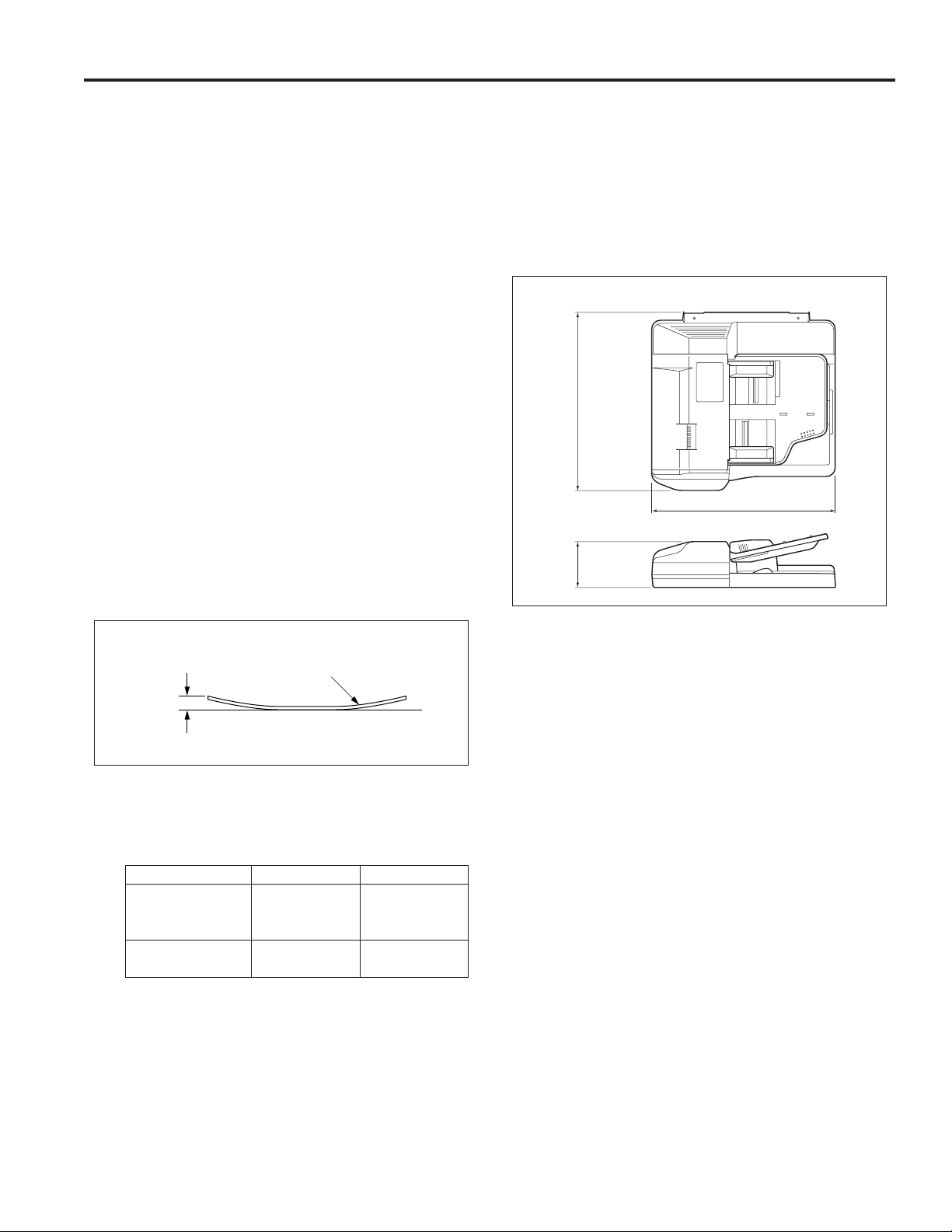
Original curling: Less than 10 mm maximum
Machine Data
Power source: 24 V DC / 5 V (supplied from the main
body)
Max. power consumption:
Less than 120 VA
Weight: Approximately 32 lb.
Machine dimensions :
Unit: mm
570
590
150
Original
Curling
Maximum number of stacked originals:
50 sheets maximum (22 lb.)
Original read speed (copies per minute)
Mode
Single-sided
original to Single-
sided copy
Dual-sided original
to duplex copy
Original feed layout: Face-up setting, centered, U-turn
Original size
8.5x11
8.5x11
feed/straight paper exit, reversal
section mounted at paper exit
side.
Feed speed
65
38
Maintenance
Maintenance: Same as the main body
Operating Environment
Temperature: 50°F ~ 91°F
Humidity: 10% to 80%RH
Note: The contents of this manual may be changed without
prior notice.
Original image read position:
At the slit glass section
1
DF-312
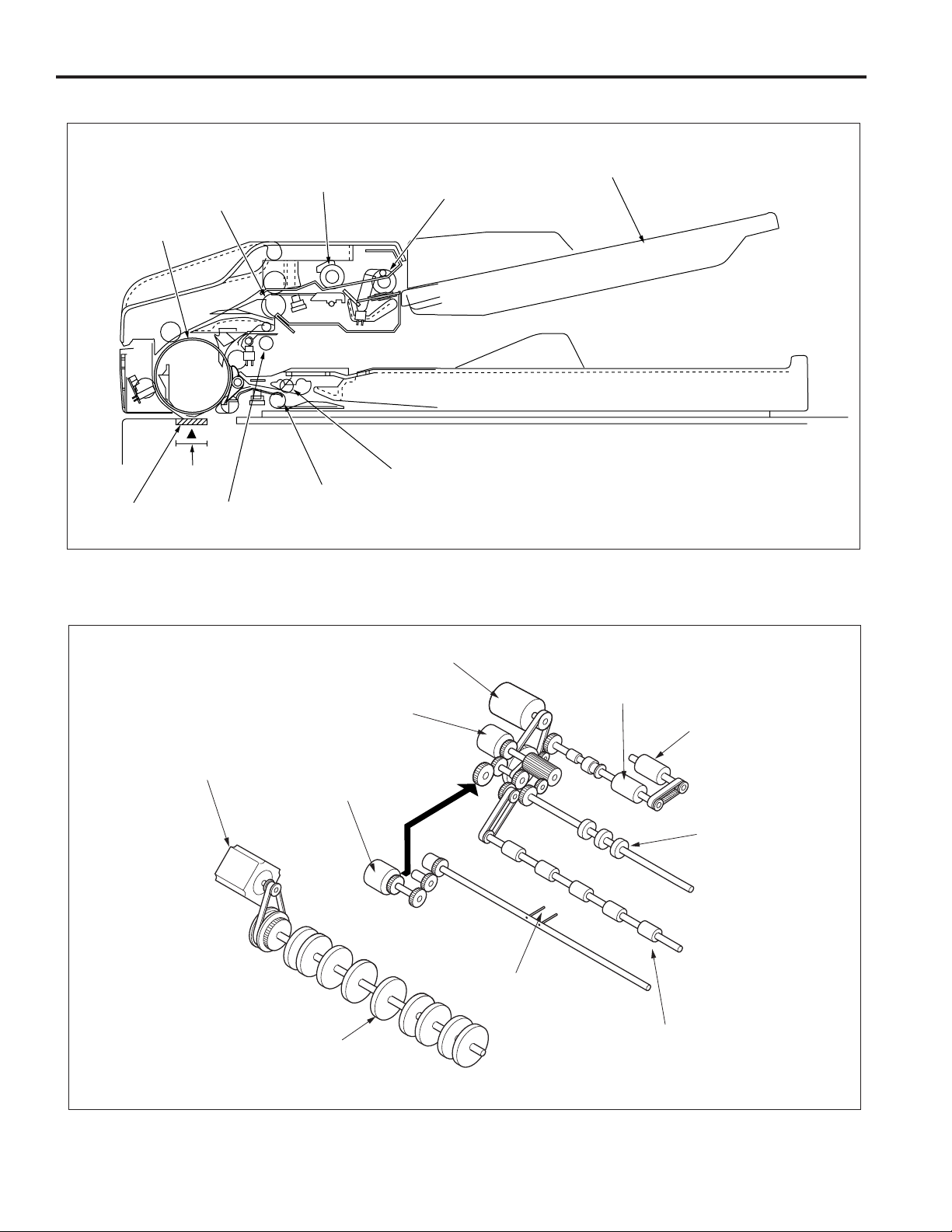
CENTER CROSS-SECTIONAL DRAWING
Registration roller
Conveyance roller
Original
image read
Slit glass
position
Separation roller
Pressure pulley
Reversal roller
Paper exit roller
Paper feed roller
DRIVE SYSTEM DRAWING
Paper feed tray
Original conveyance
motor (M301)
Original feed CL
(CL302)
Original pick-up CL
(CL301)
Conveyance roller
Original feed motor
(M302)
Separation roller
Paper feed roller
Registration roller
Pressure pin
Paper exit roller
2
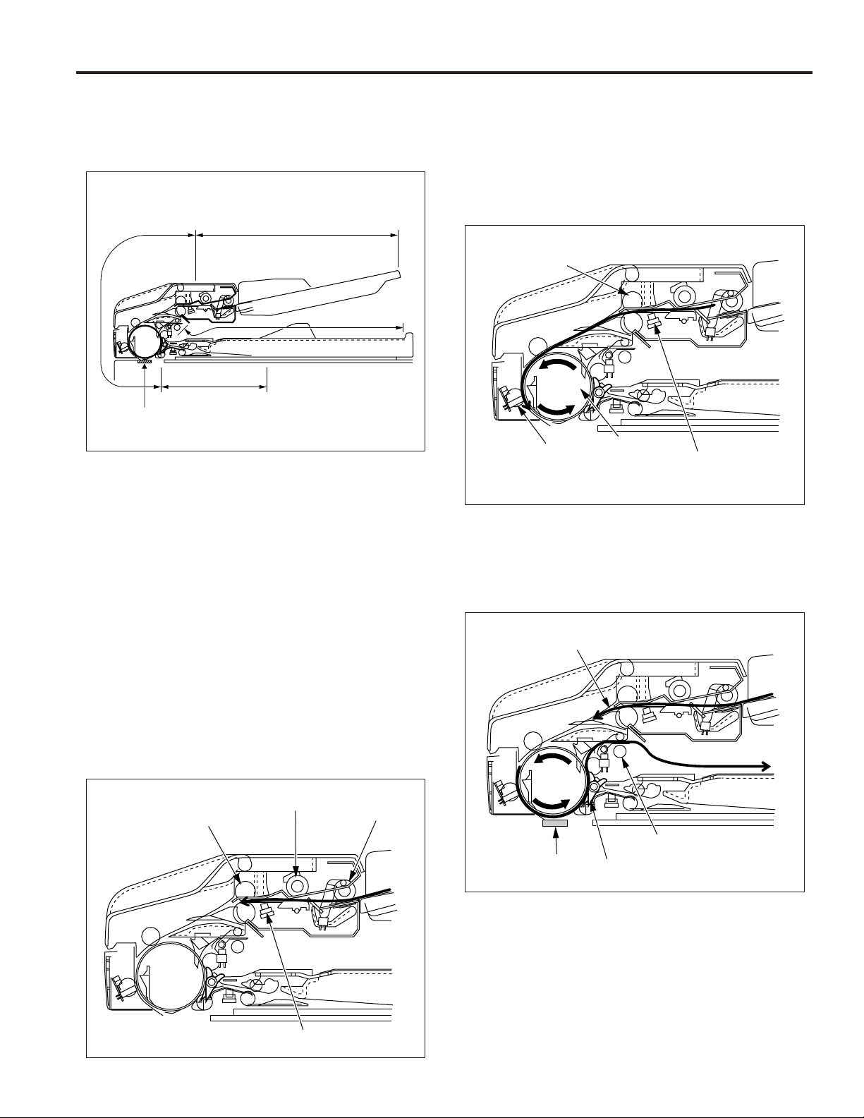
ORIGINAL CONVEYANCE PROCESS
DF-312
As the figure below shows, the DF-312 is composed of the
paper feed section, conveyance section, reversal section and
paper exit section.
Conveyance
section
Reversal section
Slit glass
(Read section)
The originals, which have been placed in the paper feed tray
with the front side facing up, are fed starting with the topmost
original. Originals that are fed are not conveyed to the original
glass. Reading is carried out as the original passes by the slit
glass section set midway through the conveyance path.
The operational modes of the DF-312 include three modes: (a)
single side original copy mode, (b) double side original copy
mode, (c) mixed original copy mode. The conveyance path is
different for each mode.
Paper feed section
Paper exit section
Single side original copy mode (single
side to single side copy, single side to
double side copy)
The originals set in the paper feed tray are fed by means of the
paper feed roller and separation roller to the position where
PS306 (original registration) goes on.
When PS306 goes on, pre-feed is carried out by the registration roller and the original is conveyed to the conveyance roller
at high speed. When PS308 (original conveyance) detects the
leading edge of the original, the conveyance roller switches to
scanning speed and conveys the original to the slit glass.
If there is next original at this time, pre-feed is carried out.
Registration roller
PS308
(Original conveyance)
Reading of the original is carried out when the original passes
over the slit glass. Originals which have been read are
conveyed around the circumference of the conveyance roller
by closing of the flapper and are ejected to the paper exit
section via the paper exit roller.
Next original
Conveyance roller
PS306
(Original registration)
Registration roller
Separation roller
Paper feed roller
PS306 (Original registration)
Paper exit roller
Slit glass
Flapper
3

DF-312
Double side original copy mode
(double side to single side copy, double side
to double side copy)
The original conveyance operation until the start of scanning
for the front side of the 1st double side original is the same as
that of the single side original copy mode.
When scanning starts and reading of the front side is completed, the original is conveyed to the reversal section when the
flapper opens and the paper exit path is blocked.
When PS309 (original reversal) detects the leading edge of the
original that has been conveyed to the reversal section and
goes ON, pressure is applied to the pressure pulley. As a
result, the reversal roller and pressure pulley clasp the original
on both sides and convey it to the inside of the reversal section.
Flapper
Pressure pulley
When scanning of the back side starts, the flapper is opened.
As a result, the original which has been read is conveyed to the
inside of the reversal section again.
Flapper
When PS309 detects the trailing edge of the original and goes
OFF, the reversal roller rotates in the reverse direction to feed
the original from the reversal section to the conveyance roller.
Since the flapper is closed at this time, the original is conveyed
along the flapper and is ejected to the paper exit section via the
paper exit roller.
Slit glass
Reversal roller
PS309 (Original reversal)
When PS309 detects the trailing edge of the original and goes
OFF, the reversal roller rotates in the reverse direction to feed
the original from the reversal section to the conveyance roller.
Since the original passes over the top of the flapper at this time,
the front and back sides are reversed and the original is sent
to the conveyance roller.
The conveyance roller conveys the original to PS308 (original
conveyance) at high speed.
When PS308 detects the leading edge of the original, the
conveyance roller switches back to scanning speed and conveys the original to the slit glass for the original to be scanned.
Flapper
PS308 (Original
conveyance
PS309 (Original reversal)
Pressure pulley
Reversal roller
Next original
Flapper
PS309 (Original reversal)
Paper exit roller
Reversal roller
Mixed original copy mode
The mixed original copy mode can handle both the same
series and different series of originals.
The size of the original in the conveyance direction is determined by the ON time of PS306, size detection operation take
place prior to the scanning operation.
The original then stops at the scanning standby position. The
subsequent operations are the same for all copy modes.
For details on the size detection operation, refer to Paper
Feed/Paper Eject section “Original Size Detection Control”.
4
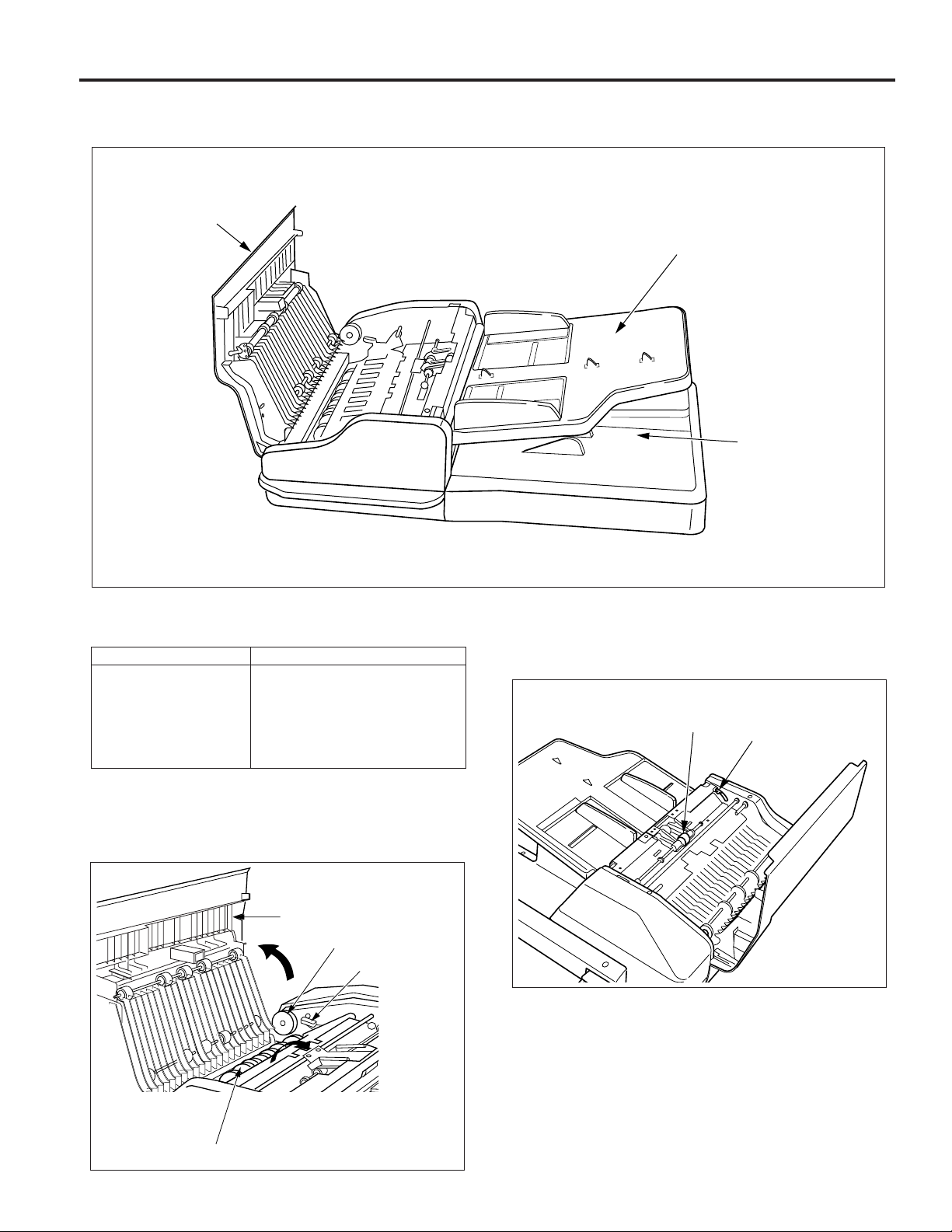
EXTERNAL SECTION
Composition
Open/close
cover
DF-312
Paper feed tray
Paper exit section
Mechanism
Mechanisms
Jam clearance
∗ 1
∗∗
∗1: Jam clearance
∗∗
If a paper jam occurs during the feed process, open the open/
close cover, raise the conveyance guide open/close lever, and
rotate the release knob to remove the jammed original.
Open/close cover
Release knob
Conveyance guide open/close lever
Pressure release lever
Platen guide
Open/close cover
Release knob
Methods
Conveyance
guide open/close
lever
If the jammed original is hard to remove, operate the pressure
release lever to remove the pressure of the separation roller,
and then remove the original.
Separation roller
Pressure release lever
Conveyance guide
5
DF-312
If a paper jam occurs during the reversal process, the jammed
original can be removed by opening the platen guide.
Lock
Platen
guide
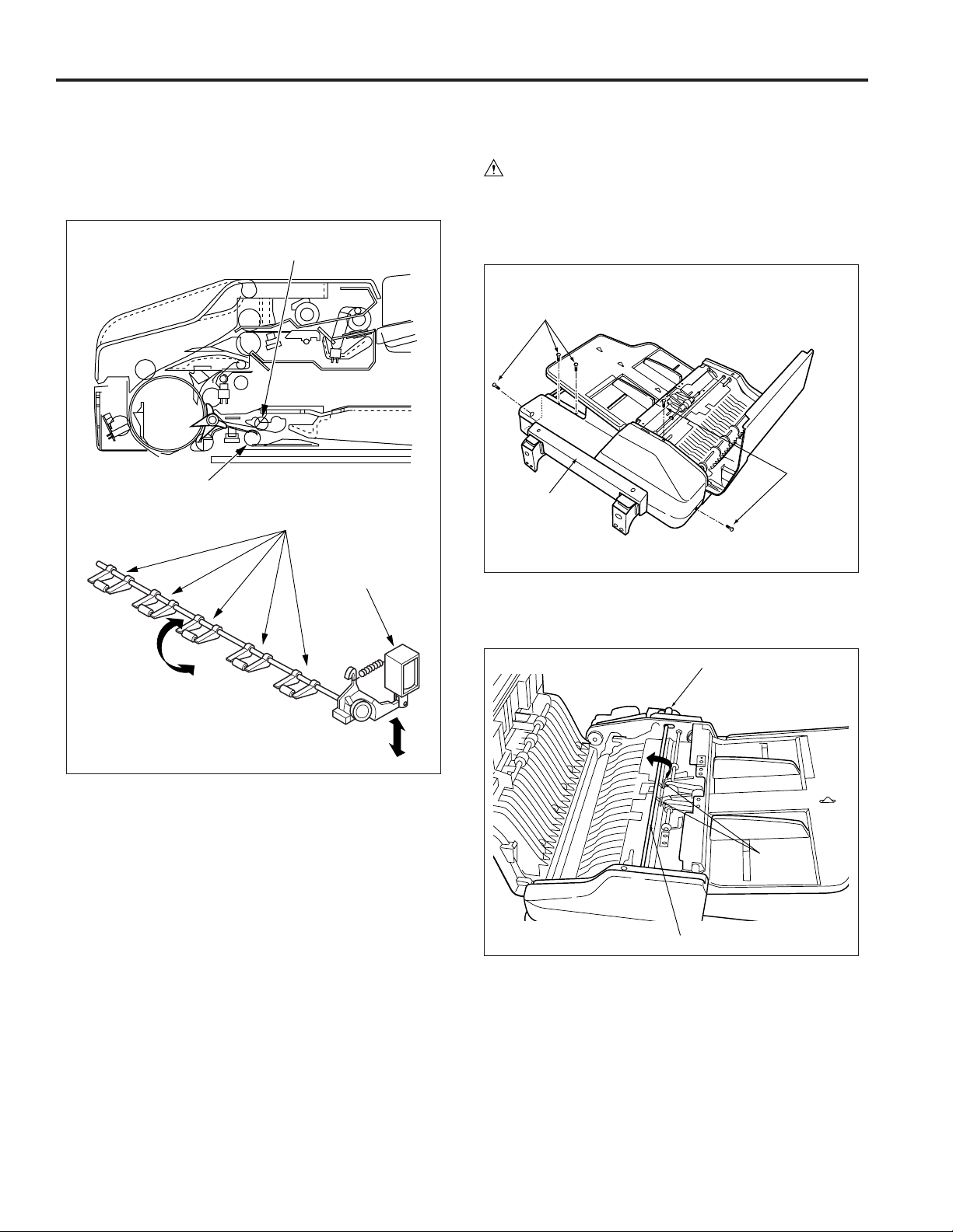
Disassembly and Reassembly
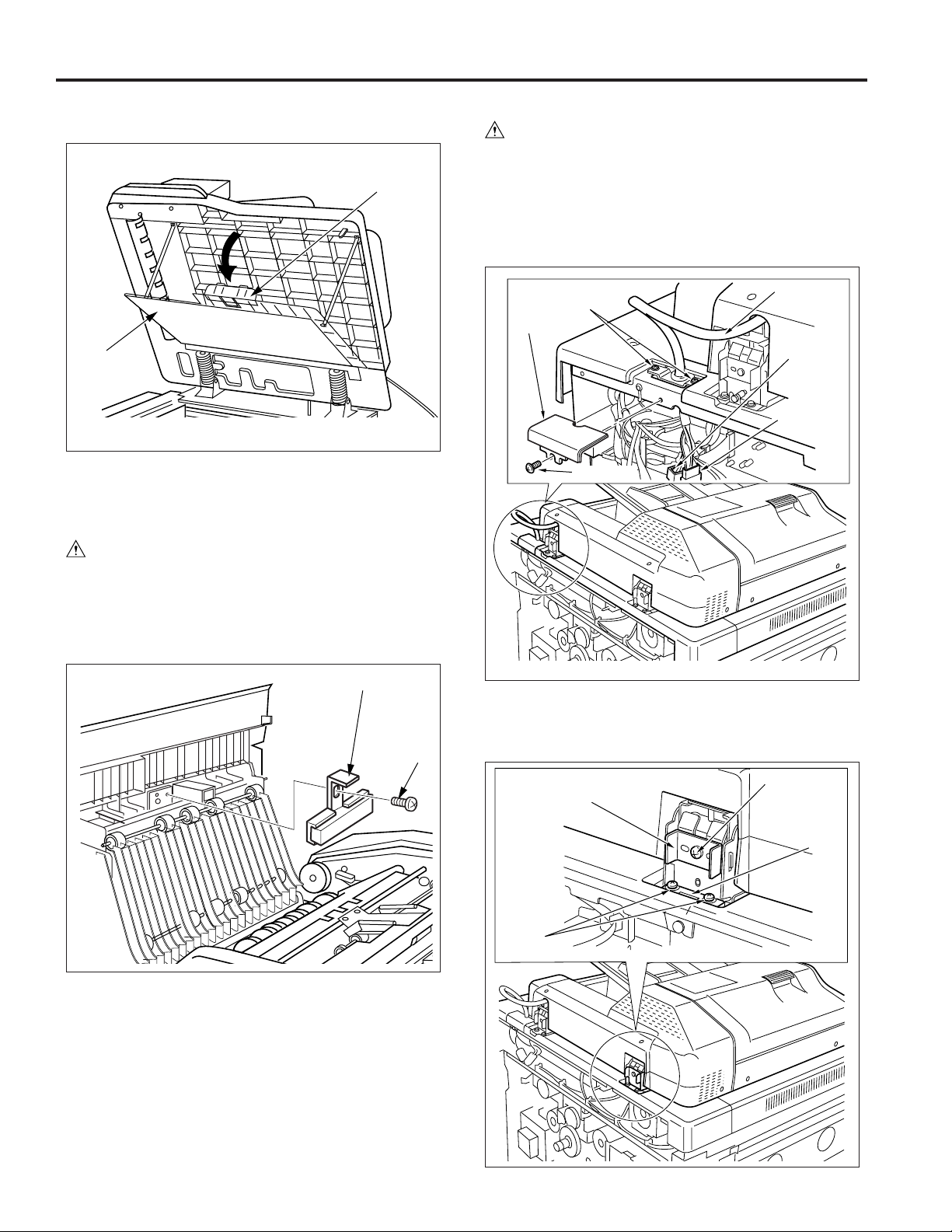
1. Removing and Reinstalling the Paper Dust
Removing Pad
Caution: Be sure that the power cord has been un-
plugged from the power outlet.
a. Procedure
(1) Open the open/close cover.
(2) Remove the set screw, then remove the paper dust
removing pad.
2. Removing the RADF
Caution: Be sure that the power cord has been un-
plugged from the power outlet.
a. Procedure
(1) Remove the rear cover.
(2) Remove the set screw, then remove the connector cover.
(3) Remove the two connectors (CN100, CN102).
(4) Remove the two set screws, then withdraw the cable from
the main body.
Connector
Set screws
cover
Set screw
Cable
Connector
(CN102)
Connector
(CN100)
Paper dust removing pad
Set screw
(3) Reinstall the paper dust removing pad in the opposite
sequence to removal.
(5) Remove the set screw from each, then remove the two
stoppers.
(6) Remove the two set screws from each, then remove the
two securing plates.
Stopper
Set
screws
Set screw
Securing
plate
6
DF-312
(7) Open the RADF.
(8) Remove the set screw from each while supporting the
RADF, then remove the two securing plates.
(9) Remove the RADF from the main body.
Securing plate/F
Set
screw
RADF
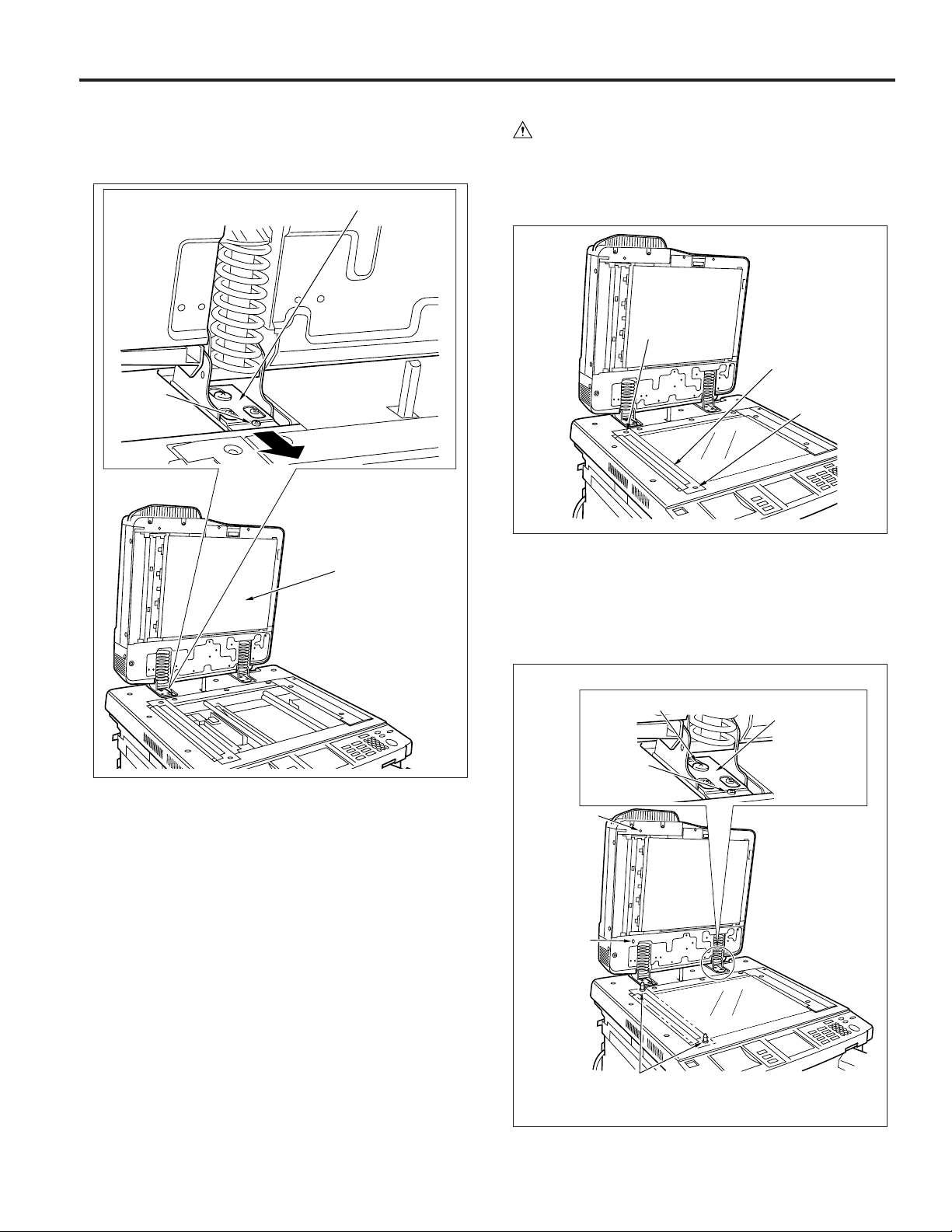
2. Reinstalling the RADF
Caution: Be sure that the power cord has been un-
plugged from the power outlet.
a. Procedure
(1) Remove the two set screws, then remove the original
stopper plate of the main body.
Set screw
Original stopper plate
Set screw
(2) Install the two RADF positioning jigs in the hole of the
original stopper plate.
(3) After reinstalling the RADF, secure the two securing
metal plates temporarily with the set screws each.
Caution: The double loop hole section of securing metal
plate must be set in the guide screw.
Caution: Be sure to support the RADF during this process as
it may fall to the rear side when the securing plate/
F has been removed.
Reference
hole
(round hole)
Reference
hole
(long hole)
Guide screw
Set screw
RADF
positioning jigs
Securing metal
plate
7
DF-312
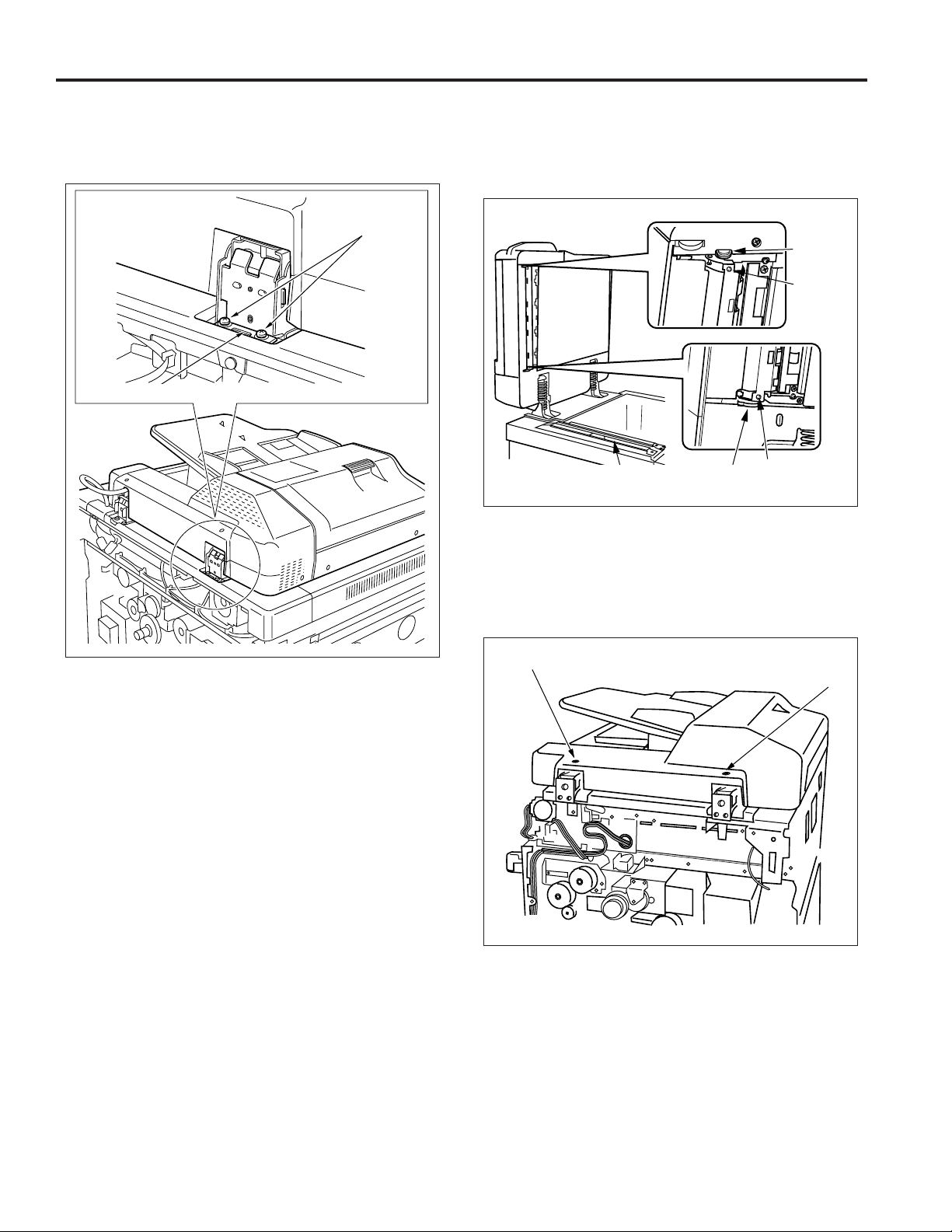
(4) Close the RADF, and match the reference hole with the
RADF positioning jig.
(5) When the two positions are matched, secure each of the
two set screws of the securing metal plate.
Set screws
Securing metal
plate
(7) Remove the two RADF positioning jigs, then install the
original stopper plate.
(8) Close the RADF, and check whether or not the stoppers
of the read section at the 2 locations contact with the slit
glass.
Stopper
Projection
Slit glass
Stopper
Projection
(9) Adjust the adjustment screws A and B alternately so that
both stoppers contact with the slit glass.
Caution: Repeat Step (8) to (9) until both stoppers make
contact with the slit glass simultaneously.
(10) Reinstalling hereafter is performed in the opposite se-
quence to removal.
(6) Open the RADF and secure each of the set screw of the
securing metal plate.
Adjustment
screw B Adjustment
screw A
8
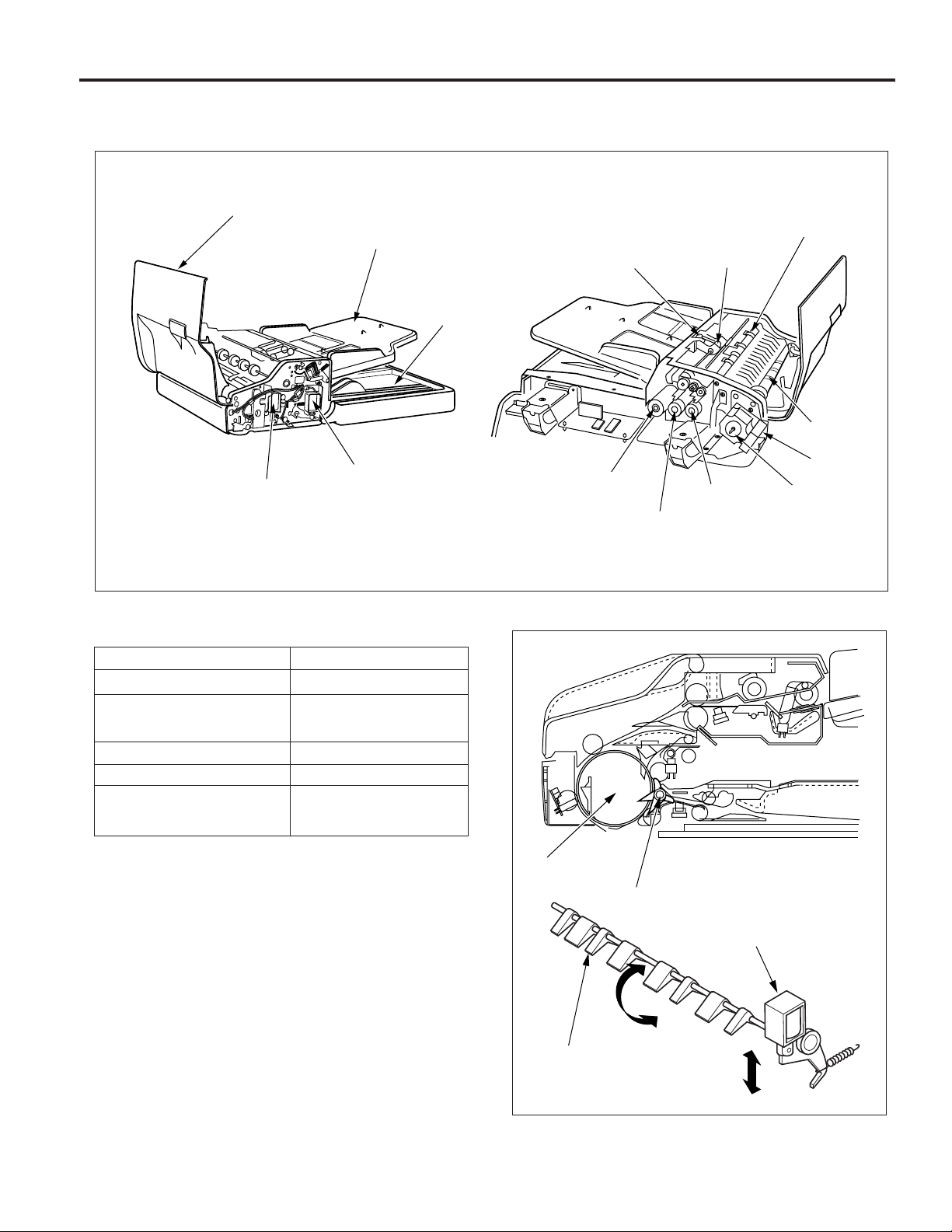
PAPER FEED/PAPER EXIT SECTION
Composition
DF-312
Mechanism
Open/close cover
Flapper solenoid
(SD301)
Paper feed tray
Paper exit tray
Original pressure
solenoid (SD302)
Paper feed roller
Original feed motor
(M302)
Original feed CL
(CL302)
Separation roller
Original
pick-up CL
(CL301)
Registration
roller
Conveyance
roller
ADF fan
(FM301)
Original
conveyance motor
(M301)
Mechanisms
Paper feed
Double feed prevention
Paper feed roller
Double feed prevention pad
Methods
Separation roller
Conveyance
Conveyance path switching
∗1
Reversal paper feed
∗2
Conveyance roller
Flapper
Reversal roller pressure
Reversal roller turn-back
∗∗
∗1: Conveyance path switching
∗∗
In the double side original copying, the conveyance path after
the end of reading operations differs for front side copies and
back side copies. Change of the conveyance path is carried
out by the flapper. Turning the flapper solenoid (SD301) ON
and OFF switches between the reversal section and the paper
exit section.
Conveyance roller
Flapper
Flapper solenoid
(SD301)
Flapper
9
DF-312
∗∗
∗2: Reversal paper feed
∗∗
During double side original copy operation, conveyance and
reversal paper feed are activated by bringing the pressure
pulleys into contact with the reversal roller. Pressure of the
pressure pulleys is driven by the original pressure solenoid
(SD302).
Pressure pulley
Disassembly and Reassembly
1. Removing and Reinstalling the paper feed
roller/separation roller
Caution: Be sure that the power cord has been un-
plugged from the power outlet.
a. Procedure
(1) Remove the five set screws, and then remove the rear
cover.
Set screws
Reversal roller
Pressure pulleys
Original pressure
solenoid (SD302)
Set screws
Rear cover
(2) Open the open/close cover.
(3) Rotate the gear until the two pressure pins on the pickup
shaft point up.
Gear
Pressure
pins
Pickup shaft
Caution: The pickup shaft cannot be turned directly. Be sure
to rotate it via the gear.
10
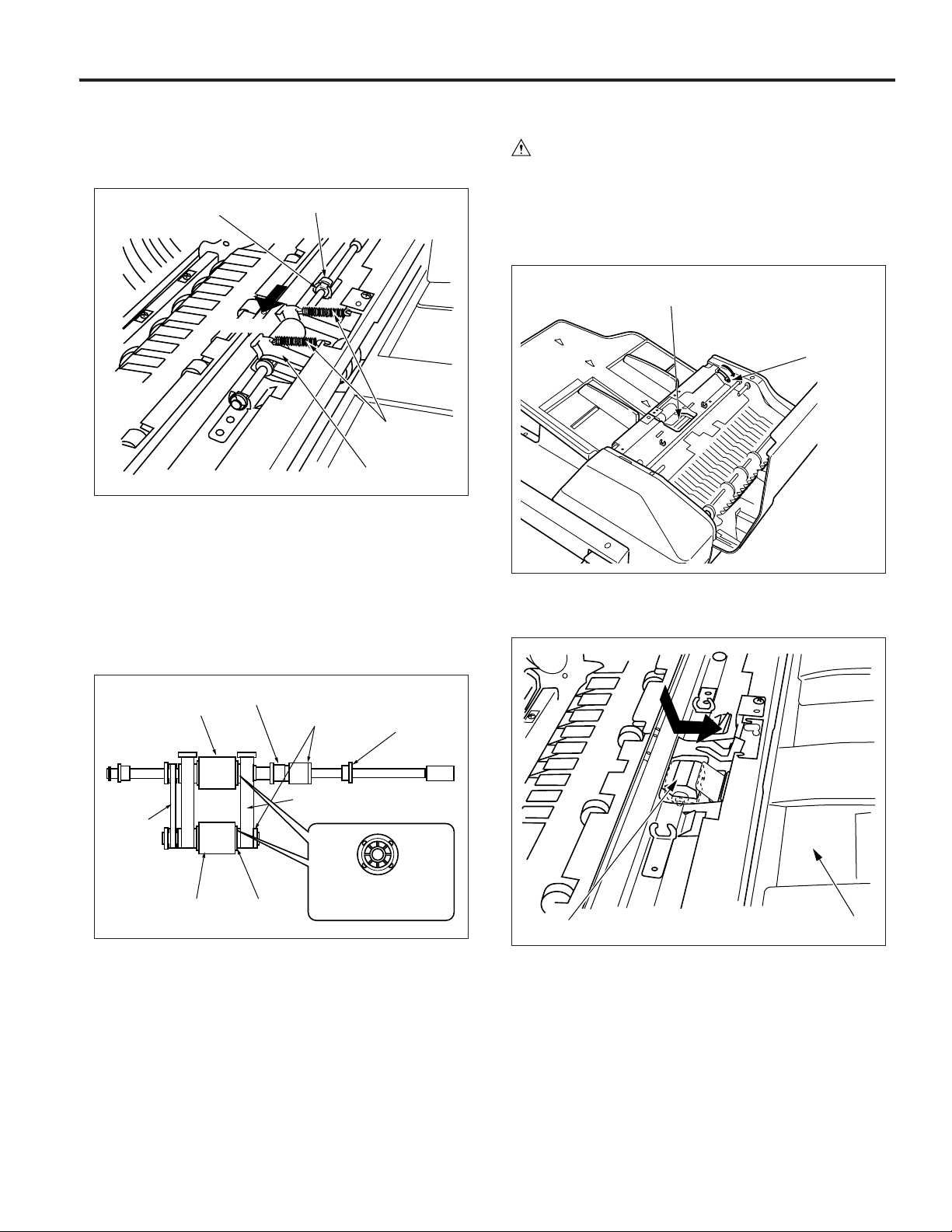
DF-312
(4) Remove the two springs.
(5) Remove the stop ring and slide the bearing to the side.
(6) Slide the paper feed roller assembly towards the front
side, then remove it.
Bearing
Front
Stop ring
Springs
Paper feed
roller assembly
(7) Remove the bearing.
(8) Remove the two stop rings, then remove the guide lever.
(9) Remove the separation roller and paper feed roller.
Caution: When reinstalling each roller, pay attention to
correct roller orientation. (The correct orientation
can be determined by looking at the side shape of
the roller.)
Do not lose the spring of the paper feed roller.
2. Removing and Re-installing the double feed
prevention pad
Caution: Be sure that the power cord has been un-
plugged from the power outlet.
a. Procedure
(1) Remove the paper feed roller assembly.
(2) Push the pressure release lever so that pressure on the
double feed prevention pad is released.
Double feed
prevention pad
Pressure
release lever
(3) Push the double feed prevention pad down, slide it
towards the paper feed tray, and then remove it.
Separation roller
Paper
feed
drive
belt
Paper feed roller
Torque limitter
Stop rings
Springs
Bearing
Guide lever
Side shape of roller
(10) Reinstall the paper feed roller and separation roller in the
opposite sequence to removal.
Double feed prevention pad
Paper feed tray
(4) Reinstall the double feed prevention pad in the opposite
sequence to removal.
11
 Loading...