

Page 1

SERVICE MANUAL
MODEL
DF-311
JUNE 1998
CSM-DF311
Page 2

Page 3

TABLE OF CONTENTS
SAFETY PRECAUTIONS ...................................................... v
DF-311
SPECIFICATIONS..................................................................1
Type ................................................................................1
Functions........................................................................1
Machine Data ................................................................. 1
Maintenance...................................................................1
Operating Environment .................................................. 1
CENTER CROSS SECTION..................................................2
DRIVE SYSTEM DIAGRAM.....................................................2
ORIGINAL CONVEYANCE PROCESS ..................................3
Single -side Original Copy Mode ................................... 3
Double-side Original Copy Mode ................................... 4
Mixed Original Copy Mode..............................................4
EXTERNAL SECTION............................................................5
Construction...................................................................5
Mechanisms...................................................................5
Disassembly and Reassembly .....................................6
PAPER FEED/PAPER EXIT SECTION...................................8
Construction...................................................................8
Mechanism.....................................................................8
Disassembly and Reassembly .....................................9
Paper Feed/Conveyance/Scan Control ........................ 1 1
Paper Exit/Reverse Conveyance Control .....................1 3
Original Size Detection Control....................................1 5
DIAGRAMS
ELECTRICAL PARTS LAYOUT DIAGRAM.........................17
CONNECTOR LAYOUT DIAGRAM ......................................18
DF-311
iii
Page 4

DF-311
This page left blank intentionally.
iv
Page 5
PRODUCT SPECIFICATIONS
DF-311
Type
Type: Sheet-through type reversible DF
Functions
Originals size: 11X17,8.5X14,8.5X11, 8.5X11R,
8.5X5.5, 8.5X5.5R, 5.5X8.5R
· Double sided copy of 5.5X8.5
originals is not possible.
· All sizes are detected
automatically.
· Mixing of original sizes
possible.
Kinds of originals
Ordinary paper: 14 to 36 lb. fine quality paper
Special paper: Paper feed and conveyance
ability may sometimes be inferior
to those of 14 to 36 lb. fine quality
paper.
The following kinds of paper
cannot be used:
· OHP film
· Blueprint masters
· Label paper
· Offset masters
· Pasted originals
Machine Data
Power source: 24 V DC / 5 V (supplied from main
body)
Max. power consumption:
40 W
Weight: Approximately 30 lb.
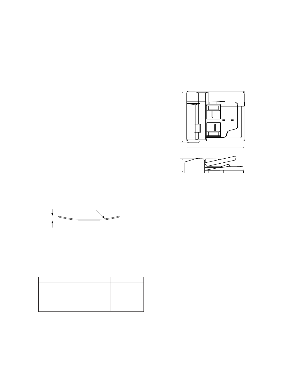
Machine dimensions :
Unit: inches
22.0
23.2
5.9
Maintenance
Maintenance: Same as main body
Original
Curling
Original curling: 10 mm maximum.
Maximum number of stacked originals:
50 sheets (22 lb.)
Original read speed (copies per minute)
Mode
Single-sided
original to Single-
sided copy
Dual-sided original
to duplex copy
Original feed layout: Face-up setting, centered, U-turn
Original size
8.5x11
8.5x11
feed/straight paper exit, reversal
section mounted at paper exit
side.
Feed speed
40
28
Operating Environment
Temperature: 50°F ~ 91°F
Humidity: 20% to 80%RH
Note: The contents of this manual may be changed without
prior notice.
Original image read position:
At the slit glass section
1
Page 6
DF-311
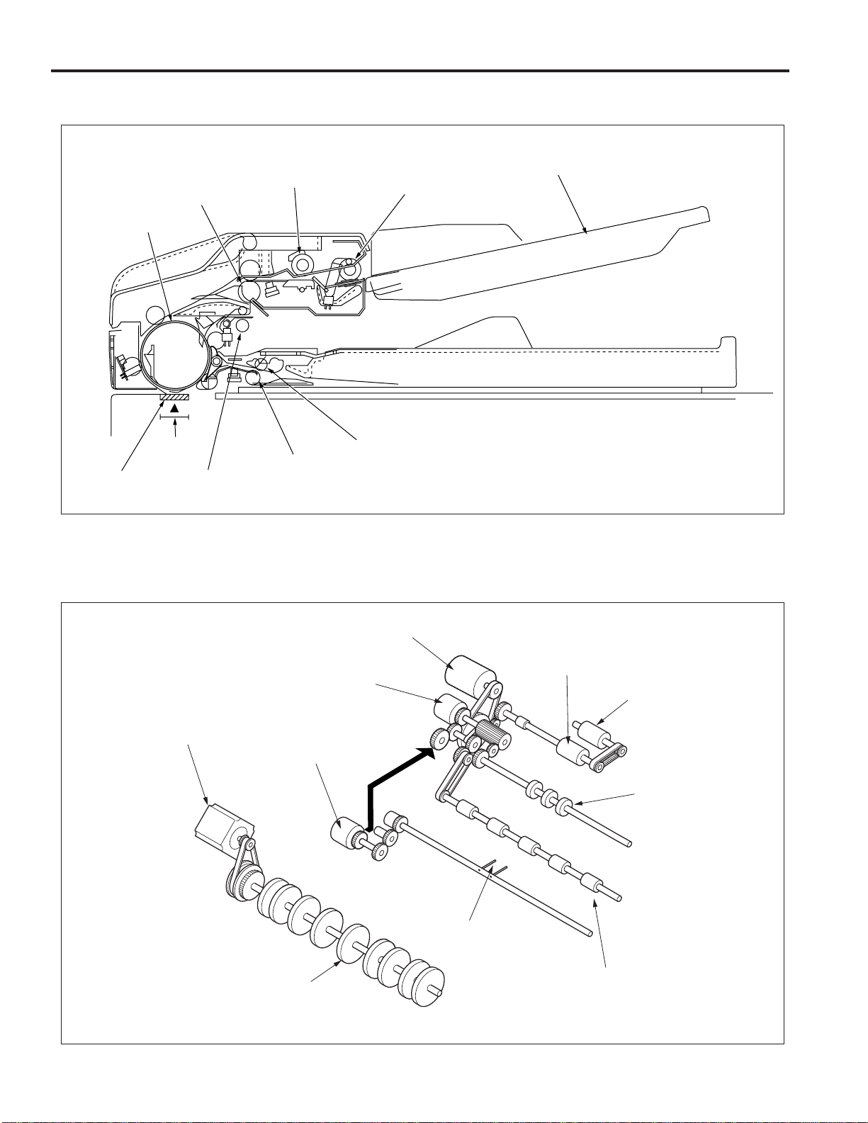
CENTER CROSS-SECTIONAL DRAWING
Registration roller
Conveyance roller
Original
image read
Slit glass
position
Separation roller
Pressure pulley
Reversal roller
Paper exit roller
Paper feed roller
DRIVE SYSTEM DRAWING
Paper feed tray
Original conveyance
motor (M301)
Original feed clutch
(CL302)
Original pick-up clutch
(CL301)
Conveyance roller
Original feed motor
(M302)
Separation roller
Paper feed roller
Registration roller
Pressure pin
Paper exit roller
2
Page 7
ORIGINAL CONVEYANCE PROCESS
DF-311
As the figure below shows, the DF-311 is composed of the
paper feed section, conveyance section, reversal section and
paper exit section.
Conveyance
section
Reversal section
Slit glass
(Read section)
Paper feed section
Paper exit section
The originals, which have been placed in the paper feed tray
with the front side facing up, are fed starting with the topmost
original. Originals that are fed are not conveyed to the original
glass. Reading is carried out as the original passes by the slit
glass section set midway through the conveyance path.
The operational modes of the DF-311 include three modes: (a)
single side original copy mode, (b) double side original copy
mode, (c) mixed original copy mode. The conveyance path is
different for each mode.
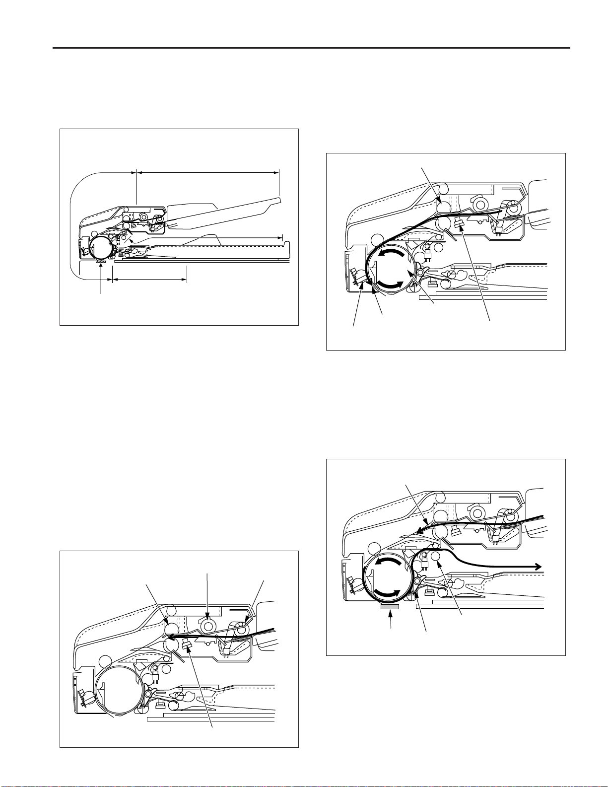
When PS306 goes on, pre-feed is carried out by the registration roller and the original is conveyed to the conveyance roller.
The conveyance roller conveys the original to the position
where PS308 (original feed detect) goes on. The original stops
at the scanning standby position.
Registration roller
Scanning standby
PS308
(Original feed detect)
position
Conveyance roller
PS306
(Original registration)
When scan is started, the conveyance roller rotates again in
the forward direction to convey the original. If there is another
original at this time, pre-feed is carried out.
Reading of the original is carried out when the original passes
over the slit glass. Originals which have been read are conveyed around the circumference of the conveyance roller by
closing of the guide plate and are ejected to the paper exit
section via the paper exit roller.
Single side original copy mode (single
side to single side copy, single side to
double side copy)
The originals set in the paper feed tray are fed by means of the
paper feed roller and separation roller to the position where
PS306 (original registration) goes on.
Separation roller
Registration roller
PS306 (Original registration)
Paper feed roller
Next original
Paper exit roller
Slit glass
Guide plate
3
Page 8
DF-311
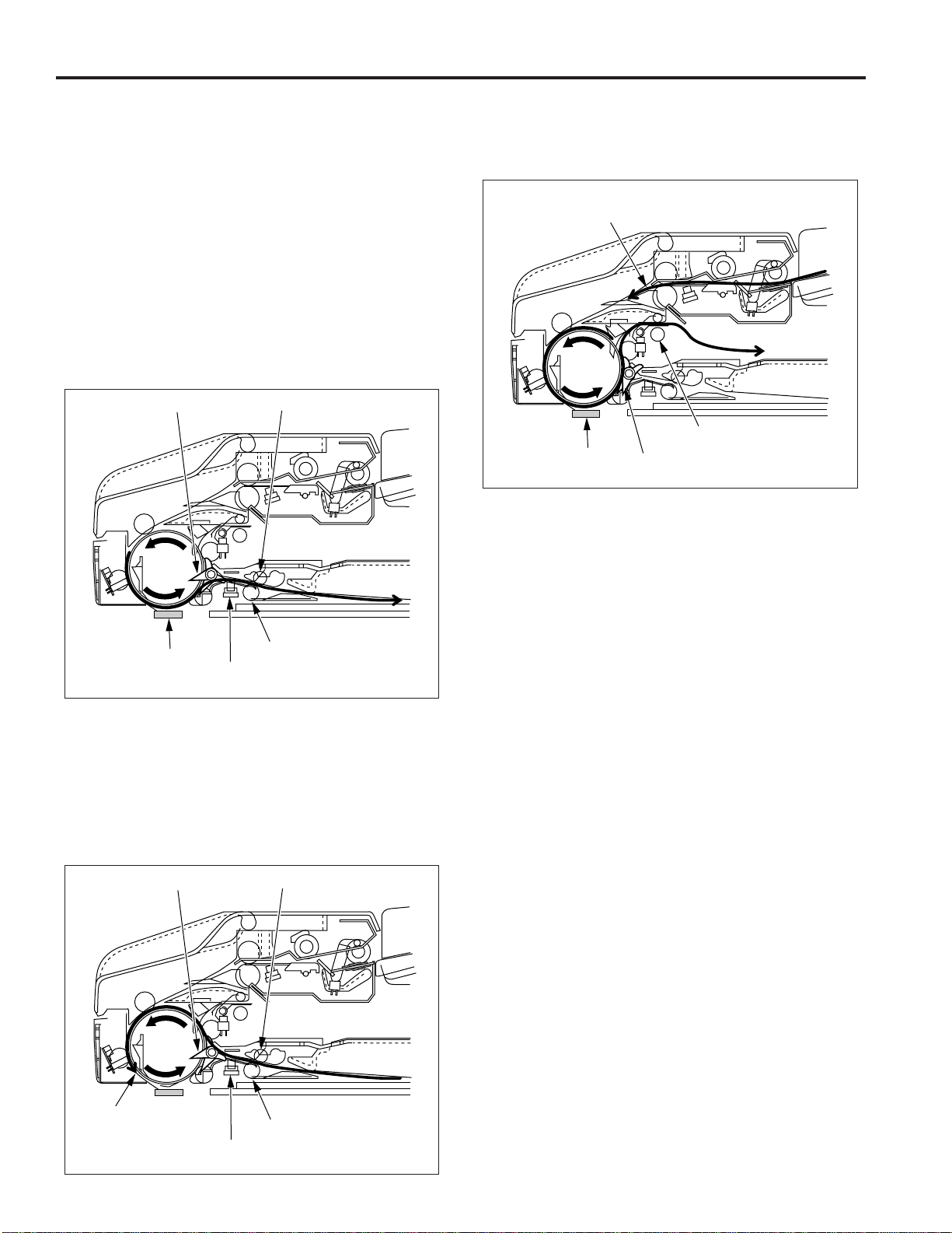
Double side original copy mode
(double side to single side copy, double side to
double side copy)
The conveyance operation from feeding of the double sided
original to the front side scanning standby position is the same
as that for the single side original copy mode.
When scanning starts and reading of the front side is completed,
the original is conveyed to the reversal section when the guide
plate opens and the paper exit path is blocked.
When PS309 (original reversal detect) detects the leading
edge of the original that has been conveyed to the reversal
section and goes ON, pressure is applied to the pressure
pulley. As a result, the reversal roller and pressure pulley clasp
the original on both sides and convey it to the inside of the
reversal section.
Guide plate
Slit glass
Pressure pulley
Reversal roller
PS309
(Original reversal)
When scanning of the back side starts, the guide plate is
closed. As a result, the original which has been read is
conveyed around the circumference of the conveyance roller
and is ejected to the paper exit section via the paper exit roller.
Next original
Paper exit roller
Slit glass
Guide plate
Mixed original copy mode
The mixed original copy mode can handle both the same
series and different series of originals.
The size of the original in the conveyance direction is determined by the ON time of PS306, size detection operation take
place prior to the scanning operation.
The original then stops at the scanning standby position. The
subsequent operations are the same for all copy modes. For
details on the size detection operation, refer to Paper Feed/
Paper Eject section “Original Size Detection Control”.
When PS309 detects the trailing edge of the original and goes
OFF, the reversal roller rotates in the reverse direction to feed
the original from the reversal section to the conveyance roller.
Since the original passes over the top of the guide plate at this
time, the front and back sides are reversed and the original is
sent to the conveyance roller.
The conveyance roller conveys the original to the scanning
standby position.
Guide plate
Scanning
standby position
Pressure pulley
Reversal roller
PS309
(Original reversal)
4
Page 9
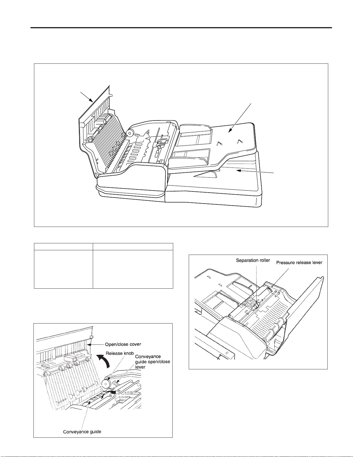
EXTERNAL SECTION
Construction
Open/close
cover
DF-311
Paper feed tray
Paper exit section
(Paper exit tray)
Mechanism
Mechanisms
Jam clearance
∗ 1
∗∗
∗1: Jam clearance
∗∗
If a paper jam occurs during the feed process, open the open/
close cover, raise the conveyance guide open/close lever, and
rotate the release knob to remove the jammed original.
Open/close cover
Release knob
Conveyance guide open/close lever
Pressure release lever
Platen guide
Methods
If the jammed original is hard to remove, operate the pressure
release lever to remove the pressure of the separation roller,
and then remove the original.
5
Page 10
DF-311
If a paper jam occurs during the reversal process, the jammed
sheet can be removed by opening the platen guide.
Lock
Platen
guide
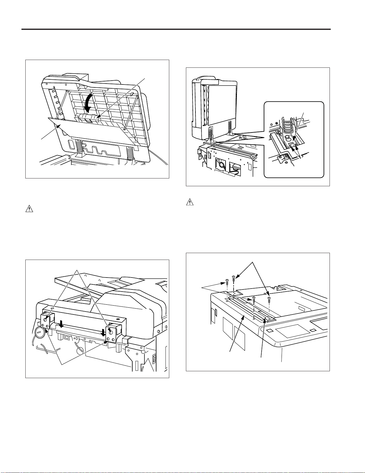
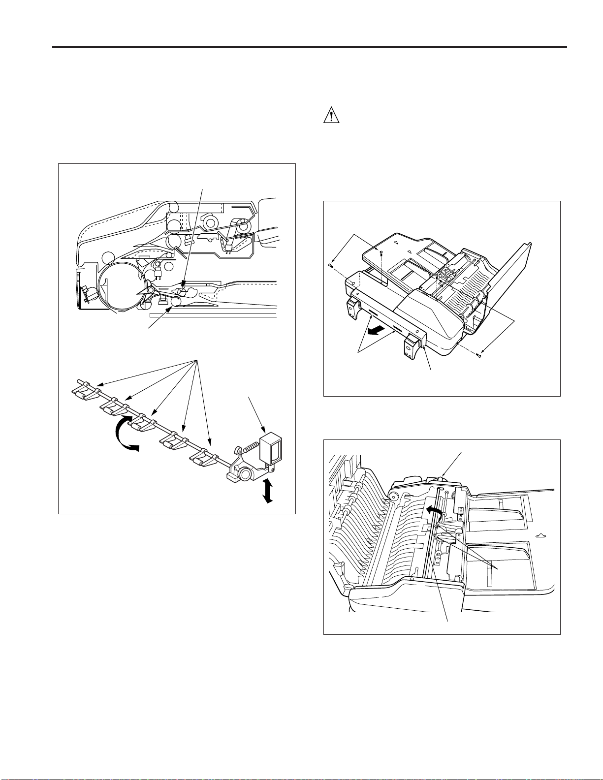
Disassembly and Reassembly
Removing the RADF
Caution: Be sure that the power cord has been un-
plugged from the power outlet.
Procedure
(1) Disconnect the RADF connector (CN100) from the right
side of the main body.
(2) Loosen the set screws of the stoppers (one each), lower
the stoppers, then tighten the screws again.
Stoppers
Caution: When the stopper brackets are removed, the RADF
will tend to fall towards the rear. To prevent this, be
sure to support it.
Stopper bracket
Set screws
Reinstalling the RADF
Caution: Be sure that the power cord has been un-
plugged from the power outlet.
Procedure
(1) Remove the two set screws, then remove the original
stopper plate.
(2) Remove the two set screws, then remove the read cover
(left).
Set screws
Set screws
(3) Raise the RADF.
(4) Remove the two set screws holding the stopper bracket.
(5) While supporting the RADF, remove the two stopper
brackets and remove the RADF.
Set
screws
Read cover (left)
Original stopper
plate
(3) Attach the two RADF position adjusting jigs to the original
stopper plate mounting holes.
(4) Install the RADF and provisionally fasten the two stopper
brackets with the set screws.
Caution: Fit the oblong cutouts in the stopper brackets onto
the guide screws.
6
Page 11
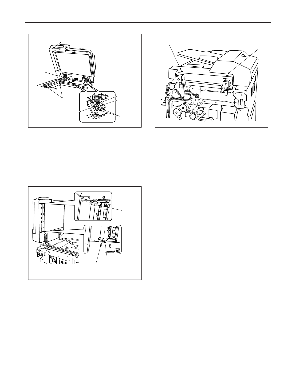
DF-311
Guide hole (round)
Guide hole
(oblong)
Guide screw
RADF position adjusting jigs
Pear-shaped
hole
Stopper
bracket
Set screws
(5) Close the RADF and slide the entire assembly back or
forward so that the guide holes match the RADF position
adjusting jigs.
(6) When the correct position has been established, carefully
open the RADF without disturbing its position and
permanently tighten the stopper brackets that were
provisionally fastened previously.
(7) Close the RADF and verify that the two read position
stoppers both contact the original glass (1).
Set screw B
Set screw A
(9) Remove the two RADF position adjusting jigs and install
the original stopper plate .
(10) Install the read cover (left).
Stopper
Projection
Projection
Original
glass (1)
Stopper
(8) Adjust set screws A and B alternately, until both stoppers
contact the slit glass.
Caution: Repeat step (8) until both stoppers contact the
original glass (1).
7
Page 12
DF-311
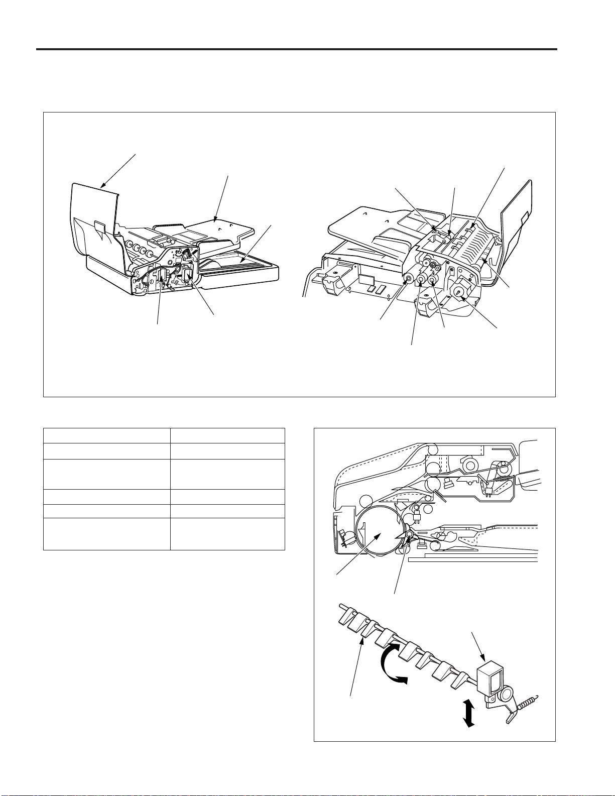
PAPER FEED/PAPER EXIT SECTION
Construction
Open/close cover
Guide plate solenoid (SD301)
Mechanism
Mechanisms
Paper feed
Double feed prevention
Conveyance
Conveyance path switching
∗1
Reversal feed
∗2
Paper feed tray
Paper exit tray
Original pressure
solenoid (SD302)
Methods
Paper feed roller
Double feed prevention pad
Separation roller
Conveyance roller
Guide plate
Reversal roller pressure
Reversal roller turn-back
Paper feed roller
Original feed motor
(M302)
Original feed clutch
(CL302)
Separation roller
Original
pick-up
clutch
(CL301)
Registration
roller
Conveyance
roller
Original
conveyance motor
(M301)
∗∗
∗1: Conveyance path switching
∗∗
In the double side original copying, the conveyance path after
the end of reading operations differs for front side copies and
back side copies. Change of the conveyance path is carried
out by the flapper. Turning the guide plate solenoid (SD301)
ON and OFF switches between the reversal section and the
paper exit section.
Conveyance roller
Guide plate
Guide plate solenoid
(SD301)
Flapper
8
Page 13
∗∗
∗2: Reversal feed
∗∗
During double side original copy operation, the original conveyed to the reversal section is held in the standby mode on the
reversal roller. Reversal feed is activated by bringing the
pressure pulleys into contact with the reversal roller. Pressure
of the pressure pulleys is conducted by the original pressure
solenoid (SD302).
Pressure pulley
Reversal roller
DF-311
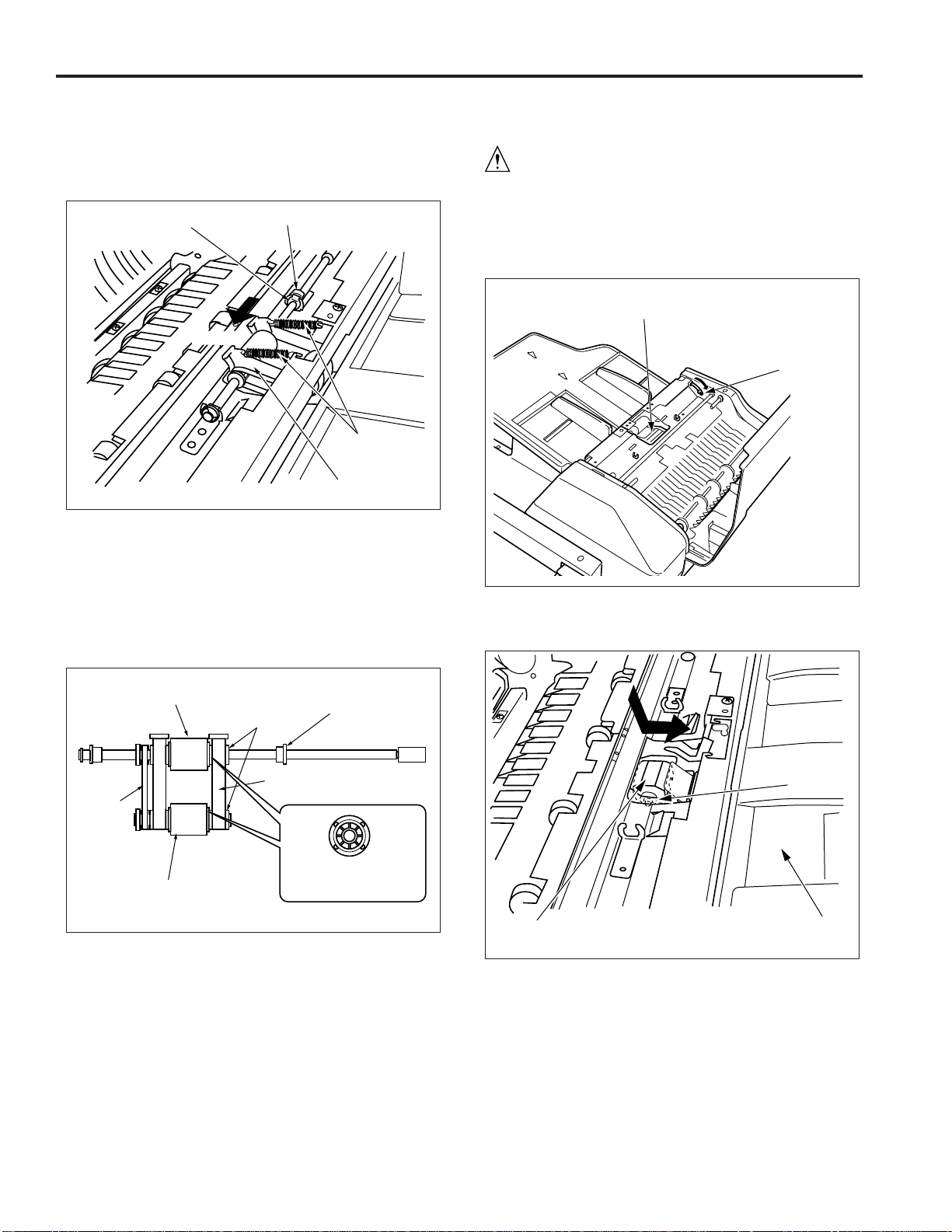
Disassembly and Reassembly
Removing and Reinstalling the paper feed roller/
separation roller
Caution: Be sure that the power cord has been un-
plugged from the power outlet.
Procedure
(1) Open the open/close cover. Remove the four set screws
to remove the rear cover.
(2) While gently pulling out at the rear to free the locating
parts.
Set screws
Set screws
Pressure pulleys
Original pressure
solenoid (SD302)
Locating parts
Rear cover
(3) Rotate the gear until the two pressure pins on the pickup
shaft point up.
Gear
Pressure
pin
Pick-up shaft
Caution: The pick-up shaft cannot be turned directly. Be sure
to rotate it via the gear.
9
Page 14
DF-311
(4) Remove the two springs.
(5) Remove the stop ring and slide the bearing to the side.
(6) Slide the paper feed roller assembly towards the front
side, then remove it.
Bearing
Front
Stop ring
Springs
Paper feed
roller assembly
(7) Remove the bearing.
(8) Remove the two stop rings, then remove the guide lever.
(9) Remove the separation roller and paper feed roller.
Caution: When re-installing the separation roller, pay atten-
tion to correct roller orientation. (The correct orientation can be determined by looking at the side
shape of the roller.)
Removing and Reinstalling the double feed
prevention pad
Caution: Be sure that the power cord has been un-
plugged from the power outlet.
Procedure
(1) Remove the paper feed roller assembly.
(2) Push the pressure release lever so that pressure on the
double feed prevention pad is released.
Double feed
prevention pad
Pressure
release lever
(3) Push the double feed prevention pad down, slide it
towards the paper feed tray, and then remove it.
Separation roller
Stop rings
Guide lever
Paper
feed
drive
belt
Paper feed roller
Bearing
Side shape of roller
(10) Reinstall the paper feed roller and separation roller in the
opposite sequence to removal.
Caution: When reinstalling the paper feed roller assembly,
ensure that the two pressure pins on the pickup
shaft point upwards.
Pressure
spring
Double feed prevention pad
Paper feed tray
(4) Reinstall the double feed prevention pad in the opposite
sequence to removal.
Caution: When re-installing the double feed prevention pad,
be sure that the double feed prevention pad pressure spring is in the correct position.
10
Page 15
DF-311
Paper feed/conveyance/scan control
Paper feed takes place by transmitting the drive force of motor
M302 (original feed) to the paper feed roller and separation
roller. Conveyance takes place by transmitting the drive force
of motor M301 (original conveyance) to the conveyance roller.
M301 and M302 are controlled by the DF CB (DF control
board).
Operation
Sensor adjustment when the power is ON.
When SW2 (sub-power) is ON, a sensitivity PS306 (original
registration) and PS308 (original feed detect) is adjusted
automatically. However, if the RADF open/close cover is open
or an original is inside of the RADF, there will be no automatic
adjustment.
Original pressure operation
When a control signal from the main body is received, CL301
(original pickup) goes ON, and after the specified time M302
starts to rotate in the forward direction. This causes the paper
feed roller to be lowered, applying pressure to the original.
After the specified time, M302 and CL301 go OFF, but the
pressure on the original is maintained.
Paper feed operation
When CL302 (original feed) goes ON, the driving force of
M302 is transmitted to the paper feed roller and the
separation roller.
CL302 goes ON at the same time as M302 performs forward
rotation. When M302 switches from forward to reverse rotation, paper feed starts.
When PS306 (original registration) goes ON, the reverse
rotation of M302 is switched OFF after the specified time.
Pre-feed of first sheet
When the reverse rotation of M302 stops, the motor starts
again to rotate in forward direction after the specified time.
This causes the original to be moved to the conveyance
roller.
At the specified time after forward rotation of M302 has
started, M301 (original conveyance) goes ON and moves
the original from the conveyance roller to the scanning
standby position.
When PS308 (original feed detect) detects the leading
edge of the original and turns ON, CL302 and M302 go OFF.
After the specified time, M301 slows down and then goes
OFF. At this point, the original still moves a small distance
further due to the inertia of the conveyance roller and then
stops. This is the scanning standby position.
Pre-feed of second and further sheets
The forward rotation of M302 starts the pre-feed process of
the following original, but because the motor immediately
goes OFF, the original temporarily stops before reaching the
conveyance roller. When M301 begins the scanning operation, the forward rotation of M302 starts again. Pre-feed of the
original then is carried out while the preceding original is being
scanned.
Scanning operation (except last original)
At the specified time after M301 goes OFF, it goes ON
again and conveys the original over the slit glass area
of the main body, where scanning is performed.
When PS306 detects the trailing edge of the original that
is being scanned and goes OFF, CL302 again goes ON
and the feed operation of the next original starts.
11
Revised 10/00
Page 16

DF-311
Scanning operation (last original)
During scanning, when M301 is ON and one of the
sensors PS302 (original size detect 1), PS303 (original
size detect 2), or PS305 (no original detect) goes OFF, the
original currently being scanned is the last one.
A sensor that is used to judge the last original differs depending
on the original size.
When PS307 (original exit detect) goes OFF, M301 also
is switched OFF after the specified time.
Original pressure release
When M301 completes the scanning operation for the last
original and goes OFF, CL301 and M302 go ON which causes
the original pressure to be released. After the specified time,
CL301 and M302 go OFF.
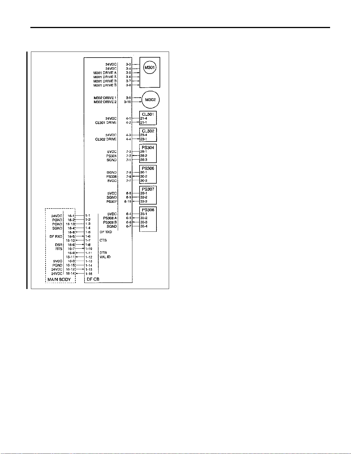
Signals
Input signals
PS302 (PS302 → PTDB → DF CB)
Original length detection signal
[L]: Original is detected
[H]: Original is not detected
PS303 (PS303 → PTDB → DF CB)
Original length detection signal
[L]: Original is detected
[H]: Original is not detected
PS304 (PS304 → DF CB)
M301 encoder surface slit detection signal
[L]: Slit is not detected
[H]: Slit is detected
PS305 (PS305 → DF CB)
No original detection signal at the paper feed tray
[L]: Original is detected
[H]: Original is not detected
PS306 (PS306 → DF CB)
Original detection signal at the conveyance roller
entrance section
[L]: Original is detected
[H]: Original is not detected
PS307 (PS307 → DF CB)
Original detection signal at the paper exit section
[L]: Original is detected
[H]: Original is not detected
PS308 A, B (PS308 → DF CB)
Original detection signal at the pre-scanning standby
position
[L]: Original is detected
[H]: Original is not detected
DF RXD (MAIN BODY → DF CB)
Serial data line for transmitting operation status information from control board in main body to RADF.
DSR (MAIN BODY → DF CB)
Send request from main body to RADF.
RTS (MAIN BODY → DF CB)
Send enable from main body to RADF.
Output signals
M301 DRIVE A, A, B, B (DF CB → M301)
M301 (original conveyance) ON/OFF drive signal
M302 DRIVE 1, 2 (DF CB → M302)
M302 drive signal
M302 rotation direction is controlled by switching the
current direction of these two signals.
State
Forward rotation
Reverse rotation
Stop
CL301 DRIVE (DF CB → CL301)
CL301 (original pick-up) ON/OFF drive signal
[L]: CL301 ON
[H]: CL301 OFF
CL302 DRIVE (DF CB → CL302)
CL302 (original feed) ON/OFF drive signal
[L]: CL302 ON
[H]: CL302 OFF
DF TXD (DF CB → MAIN BODY)
Serial data line for transmitting operation status information from RADF to main body control board.
DTR (DF CB → MAIN BODY)
Send request from RADF to main body.
CTS (DF CB → MAIN BODY)
Send enable from RADF to main body.
VAL ID (DF CB → MAIN BODY)
Image forming start signal
M302 DRIVE 1
H
L
L
M302 DRIVE 2
L
H
L
12
Page 17

Paper exit/reverse conveyance control
DF-311
Paper path switching in the exit area is carried out by
solenoid SD301 (guide plate) which operates a guide plate.
In duplex copy mode, the pressure pulley in the reversal
section is operated by the SD302 (original pressure).
SD301 and SD302 are controlled by the DF CB (DF control
board).
PS307
Operation
Sensor adjustment when the power is ON.
When SW2 (sub power) is ON, a sensitivity of PS309 (original
reversal detect) is adjusted automatically. However, if the
RADF open/close cover is open or an original is in the inside of
the RADF, there will be no automatic adjustment.
13
Revised 10/00
Page 18

DF-311
Paper exit operation
In single-sided copy mode and when copying the reverse side
of a sheet in duplex copy mode, SD301 is OFF and the flapper
is closed. The original is therefore conveyed to the paper exit
section after scanning.
Reversal paper exit operation
When copying the first side of a sheet in duplex copy mode, at
the specified time after M301 (original conveyance) goes ON
and scanning starts, SD301 goes ON and the flapper opens.
This causes the original to be sent to the reversal section after
scanning.
At the same time as SD301 goes ON, M302 (original feed)
starts reverse rotation and the drive force is transmitted to the
reversal roller.
When PS309 (original reversal detect) detects the leading
edge of the original and goes ON, the SD302 goes ON after the
specified time and applies pressure to the pressure pulley. As
a result, the original which has been conveyed to the reversal
section is caught between the reversal roller and pressure
pulley, and conveyed to the inside of the reversal section.
Reversal feed operation
When PS309 detects the trailing edge of the original and goes
OFF, both the M301 and M302 go OFF after the specified time,
and conveyance operation of the original is stopped.
After a predetermined OFF interval, M302 starts reverse
rotation and feeds the original to the conveyance roller side of
the reversal section. At this time, PS309 again goes ON and
SD302 goes OFF after the specified time. M302 goes OFF
after the specified time from PS309 goes OFF.
Pre-feed operation of next original when reading back
side of original
When PS309 goes OFF, M301 and M302 start forward rotation
after the specified time, and next original pre-feed is carried
out.
Signals
Input signals
PS304 (PS304 → DF CB)
M301 encoder surface slit detection signal
[L]: Slit is not detected
[H]: Slit is detected
PS307 (PS307 → DF CB)
Original detection signal at the paper exit section
[L]: Original is detected
[H]: Original is not detected
PS309 (PS309 → DF CB)
Original detection signal at the reversal section
[L]: Original is detected
[H]: Original is not detected
DF RXD (MAIN BODY → DF CB)
Serial data line for transmitting operation status informa
tion from control board in main unit to RADF.
DSR (MAIN BODY → DF CB)
Send request from main body to RADF.
RTS (MAIN BODY → DF CB)
Send enable from main body to RADF.
Output signals
M301 DRIVE A, A, B, B (DF CB → M301)
M301 (original conveyance) ON/OFF drive signal
M302 DRIVE 1, 2 (DF CB → M302)
M302 drive signal
M302 rotation direction is controlled by switching the
current direction of these two signals.
State
Forward rotation
Reverse rotation
Stop
SD301 DRIVE (DF CB → CL301)
SD301 (flapper ) ON/OFF drive signal
[L]: SD301 ON
[H]: SD301 OFF
SD302 DRIVE (DF CB → SD302)
SD302 (original pressure) drive signal
[L]: SD302 ON
[H]: SD302 OFF
DF TXD (DF CB → MAIN BODY)
Serial data line for transmitting operation status informa
tion from RADF to main body control board.
DTR (DF CB → MAIN BODY)
Send request from RADF to main body.
CTS (DF CB → MAIN BODY)
Send acknowledgment from RADF to main body.
VAL ID (DF CB → MAIN BODY)
Image forming start signal
M302 DRIVE 1
H
L
L
M302 DRIVE 2
L
H
L
14
Page 19

DF-311
Original size detection control
Operation
Normal copy mode
The DF CB detects the original size from a combination of the
following signals.
(1) Detection of size in the direction of the drum shaft (width)
The guide plate is connected to the VR301 and the
resistance value differs according to the position of the
guide plate. Thus, it is possible to detect the width
measurements of the original.
(2) Detection of size in the direction of original feed
There is detection of the length measurements
of the original according to a combination of ON/OFF of
PS302 and PS303.
Original size detection in the mixed original copy mode.
Judgment of size in the mixed original copy mode is carried out
under the following conditions.
(1) Size detection in the direction of drum shaft (width).
There is judgment of the width measurements of the
largest original of the mixed originals by means of the
guide plate position.
(2) Detection of size in the conveyance direction of the
original.
There is judgment of the length measurements of the
originals according to the time when PS306 (original
registration) goes ON after feeding of the original from the
registration roller.
(3) Size detection operation according to the direction of
original feed.
When original pre-feed is started with the registration
roller, M301 (original feed detect) rotates forward after
the specified time from PS306 goes ON and the original
is conveyed to the paper exit section. The forward
rotation of the M301 is continued until PS306 detects the
trailing edge of the original and goes OFF. At this time,
depending on the ON time of PS306, there is detection of
the size of the original feed direction.
The size of the original placed in the paper feed tray is detected
by PS302 (original size detect 1), PS303 (original size detect
2), and VR301 (original size detect).
PS302, PS303, and VR301 are controlled by the DF CB (DF
control board) via the PTBD (Paper tray board).
Inside the DF CB is a non-volatile memory for recording the
timing data and original size detection threshold values.
15
Registration roller
PS308
(Original feed detect)
PS306
(Original registration)
Conveyance roller
Page 20

DF-311
M301 rotates in the reversal direction after the specified time
from PS306 goes OFF and returns the leading edge of the
original that has been conveyed to the paper exit section to the
scanning standby position. The trailing edge of the original
which has been returned is conveyed to the exit section due to
the configuration of the conveyance section. The reversal
rotation of the M301 stops after the specified time from PS308
(original feed detect) detects the leading edge of the original
and goes ON.
Scanning standby
position
PS308
(Original feed detect)
Conveyance roller
List of the possible mixing of sizes.
(
: Same size : Same series : Different series ✕ : Mixing
not possible – : Setting not possible.)
(1) AB series
Standard original (maximum original size that is detected with the guide plate).
A4 B4 B5 A5R B6RA3 B5RA5A4R
A3
A4
B4
B5
A4R
A5
Other originalsOther originals
B5R
A5R
B6R
✕
✕
–
–
–
–
–
–
–
–
–
–
–
–
–
–
–
–
–
–
–
–
–
–
–
–
✕
✕
✕
✕
✕
✕
✕
✕
✕
✕
✕
–✕
✕
(2) Inch series
Standard original (maximum original size that is detected with the guide plate).
11x17 8.5x5.5
11x17
8.5x11
8.5x14
8.5x11R
8.5x5.5
8.5x5.5R
8.5x11 8.5x14
✕
–
–
✕✕
8.5x11R
–
–
✕
8.5x5.5R
–
–
✕
–
–
–
–
–
–
–
–
–
–
–
–
–
Following this, there is the same reading as in the normal mode
(scanning operation).
2nd original
1st original
The original size detection operation with the second original
and subsequent originals has a different start timing for the
single side mode and double side mode.
Single side mode: At time of starting scanning operation of
former original.
Double side mode: At time of starting scanning operation of
former original back side.
Signals
Input signals
PS302 (PS302 → PTBD → DF CB)
Original length detection signal
[L]: Original is detected
[H]: Original is not detected
PS303 (PS303 → PTBD → DF CB)
Original length detection signal
[L]: Original is detected
[H]: Original is not detected
VR301 (VR301 → PTBD → DF CB)
Original width detection signal
DF RXD (MAIN BODY → DF CB)
Serial data line for transmitting operation status informa
tion from control board in main body to RADF.
DSR (MAIN BODY → DF CB)
Send request from main body to RADF.
RTS (MAIN BODY → DF CB)
Send acknowledgment from main body to RADF.
Output signals
DF TXD (DF CB → MAIN BODY)
Serial data line for transmitting operation status informa
tion from RADF to main body control board.
DTR (DF CB → MAIN BODY)
Send request from RADF to main body.
CTS (DF CB → MAIN BODY)
Send enable from RADF to main body.
16
Page 21

ELECTRICAL PARTS LAYOUT DRAWING
8
7
6
9
19
DF-311
2
14
15
10
1. Switches and Sensors
1 MS301 Cover open/close detect MS
2 PS301 RADF open/close detect PS
3 PS302 Original size detect sensor 1
4 PS303 Original size detect sensor 2
5 PS304 Motor clock detect sensor
6 PS305 No original detect sensor
7 PS306 Original registration sensor
8 PS307 Original exit detect sensor
9 PS308 Original feed detect sensor
10 PS309 Original reversal detect sensor
11 VR301 Original size detect VR
3
411
13
18
5
1
17
16
12
2. Loads
12 M301 Original conveyance motor
13 M302 Original feed motor
14 SD301 Guide plate solenoid
15 SD302 Original pressure solenoid
16 CL301 Original pick-up clutch
17 CL302 Original feed clutch
3. PCBs and Others
18 DFCB DF control board
19 PTBD Paper tray board
17
Page 22

DF-311
CONNECTOR LAYOUT DRAWING
33(W:3 PIN)
10(W:5 PIN)
16(GY:16 PIN)
35(W:4 PIN)
40/41(W:4 PIN)
28(W:3 PIN)
15(W:3 PIN)
37(W:2 PIN)
31/32(W:3 PIN)
42/43(W:3 PIN)
30(W:3 PIN)
29(W:3 PIN)
34(W:4 PIN)
18(W:11 PIN)
12(W:3 PIN)
11(W:6 PIN)
39(W:2 PIN)
25(W:3 PIN)
26(W:3 PIN)
20(W:3 PIN)
21(W:4 PIN)
23(W:4 PIN)
1(GY:16 PIN)
2(W:3 PIN)
18
3(W:10 PIN)
4(W:4 PIN)
5(W:5 PIN)
6(W:10 PIN)
7(W:9 PIN)
8(W:5 PIN)
Page 23

PARTS CATALOG
MODEL
DF-311
Used on Models 7033 & 7040
JUNE 1998
CSM --DF311
Page 24

Page 25

How to use this catalog
This parts catalog includes illustrations and part numbers for all replacement parts and assemblies used in this model.
Model-specific parts are identified in the illustrations with reference
numbers. Use the reference number to locate the corresponding part
number on the facing page.
Common hardware items, such as screws, nuts, washers, and pins, are
identified in the illustrations with reference letters. Use the reference letter to locate the corresponding part number on the hardware listing in the
lower right corner of the facing page.
If you know a part number, but don’t know where the part is used, use
the numerical index to determine the page number and reference number for that part. Because some common parts are used in several
places, there may be more than one entry. Refer to the illustrations to see
where the part may be used.
If you know a part’s description, but don’t know where to look to find
the part number, use the alphabetical index to determine likely page and
reference numbers. Then look at the illustrations to determine that you
have identified the correct part. Locate the part number using the listing
on the opposite page.
Retail pricing that appears with the numerical index, while valid when
this catalog was printed, is subject to change without notice. The prices
are only suggested prices and are provided only for reference. Dealers
may determine their own selling prices. For up-to-date pricing, refer to
current Konica price lists or contact the Konica Parts Distribution Center.
How to order parts
Use standard Konica parts ordering procedures to obtain these parts. For
ordering options, contact Konica’s Parts Distribution Center.
When ordering parts, be sure to specify part numbers exactly as listed in
this catalog.
NOTE: Electrical parts may include previously used components.
Model DF-311 Konica Business Technologies, Inc. Page iii
1st Edition June, 1998
Page 26

This page left blank intentionally.
Page iv Konica Business Technologies, Inc. Model DF-311
June, 1998 1st Edition
Page 27

How to use this catalog . . . . . . . . . . . . . . . . . . . . . . . . . iii
Contents . . . . . . . . . . . . . . . . . . . . . . . . . . . . . v
Machine parts
DF-311 . . . . . . . . . . . . . . . . . . . . . . . . . . . . . 2
Wiring . . . . . . . . . . . . . . . . . . . . . . . . . . . . 18
Alphabetical index . . . . . . . . . . . . . . . . . . . . . . . . . . . 21
Numerical index, Retail price list . . . . . . . . . . . . . . . . . . . . 23
Contents
Model DF-311 Konica Business Technologies, Inc. Page 1
1st Edition June, 1998
Page 28

DF-311
Page 2 Konica Business Technologies., Inc. Model DF-311
June, 1998 1st Edition
Page 29

REF. PART NUMBER DESCRIPTION
NO.
1 120A10450 Ground spring
2 120A10350 Stopper
3 120A12050 Rear cover
4 120A12040 Cover
5 120A-1140 Hinge (left) ass’y
6 * Not used
7 120A10140 Bracket
8 120A10150 Base plate
9 120A-9010 DF-311 control board
10 120A-9510 EPROM
11 120A12060 Front cover
12 120A12010 Base cover
13 120A14040 Stopper arm
14 120A-1410 Pressure plate ass’y
15 120A10130 Reinforcing plate
16 120A-1180 Hinge right ass’y
17 * Not used
18 120A10220 Hinge fixed screw
19 120A10200 ADJ plate
20 120A10210 Hinge screw
Model DF-311 Konica Business Technologies., Inc. Page 3
1st Edition June, 1998
Page 30

DF-311
Page 4 Konica Business Technologies., Inc. Model DF-311
June, 1998 1st Edition
Page 31

REF. PART NUMBER DESCRIPTION
NO.
1 120A12030 Open-close cover handle
2 120A12020 Open-close cover
3 120A10190 Guide plate spring
4 120A45060 Roller
5 120A45610 Roller shaft
6 120A45600 Open-close roller plate spring
7 120A10170 Open-close cover lever
8 120A10180 Open-close cover spring
9 120A45570 Spring
10 120A45170 Reflect plate
11 120A10160 Open-close cover shaft
12 120A45590 Roller
13 120A45580 Roller shaft
14 120A45240 Roller
15 120A97010 Seal
16 120A45510 Guide plate (A)
17 120A45530 Exit roller plate spring
18 120A45520 Paper exit roller
19 120A45540 Guide plate (B)
20 120A45560 Spring
21 120A73030 Spring
22 120A73020 Actuator
23 120A85520 Photosensor
24 120A73010 Sensor holder
25 120A45100 Roller plate spring
26 120A73040 Harness plate
27 120A10070 Upper guide
28 120A45080 Roller shaft
29 120A45090 Roller
30 120A45070 Roller
31 120A-1210 Fulcrum plate ass’y
32 120A77050 Gear
33 120A77030 Gear
34 120A45680 Bushing
35 * Not used
36 120A10080 Side plate front ass’y
37 120A-1030 Side plate rear ass’y
38 120A45550 Guide
39 120A10230 Bracket
40 120A10330 Cushion
41 * Not used
42 120A45700 Shaft holder
43 120A45690 Bushing
Model DF-311 Konica Business Technologies., Inc. Page 5
1st Edition June, 1998
Page 32

DF-311
Page 6 Konica Business Technologies., Inc. Model DF-311
June, 1998 1st Edition
Page 33

REF. PART NUMBER DESCRIPTION
NO.
1 120A80010 Motor
2 120A45200 Gear
3 120A15080 Paper reverse tension spring
4 120A45190 Shaft gear
5 120A77030 Gear
6 120A77020 Gear
7 120A15060 Motor tension plate
8 120A15070 Motor mounting plate
9 120A15020 Belt (L=200)
10 120A76520 Pulley (Z=50,88)
11 120A75010 Bearing
12 120A77010 Gear (Z=20)
13 120A77040 Gear (Z=20,50)
14 120A10020 Adjusting plate (rear)
15 120A10010 Spacer rear
16 120A10060 Bracket
17 120A73050 Bracket sensor
18 120A85540 Read sensor
19 120A-4520 Roller plate spring ass’y
20 120A45020 Sensor mylar
21 * Not used
22 * Not used
23 * Not used
24 * Not used
25 120A45180 Shaft roller ass’y
26 120A10090 Spacer front
27 120A10050 Guide (rear)
28 120A-1060 Guide ass’y (rear)
29 * Not used
30 * Not used
31 * Not used
32 * Not used
33 * Not used
34 * Not used
35 120A45680 Bushing
36 120A76510 Pulley
37 120A77060 Gear
38 120A90060 Wiring ass’y read sensor
Model DF-311 Konica Business Technologies., Inc. Page 7
1st Edition June, 1998
Page 34

DF-311
Page 8 Konica Business Technologies., Inc. Model DF-311
June, 1998 1st Edition
Page 35

REF. PART NUMBER DESCRIPTION
NO.
1 120A45130 Front guide
2 120A45120 Rear guide
3 120A45140 Upper shaft spacer
4 120A45110 Shaft (upper)
5 120A45150 Pressure roller fulcrum shaft
6 120A45160 Lower guide
7 120A44020 Roller
8 120A44030 Pressure roller spring
9 120A44010 Roller arm
10 120A44040 Pressure holder pin
11 120A45040 Guide plate
12 120A45060 Roller
13 120A45050 Roller shaft
14 120A-4750 Solenoid ass’y
15 120A73160 Solenoid mounting plate
16 120A44050 Lever
17 120A44080 Lever spring
18 120A44060 Separate arm
19 120A44070 Separator spring
20 120A-4430 Solenoid ass’y
21 120A73150 Solenoid mounting plate
22 120A45030 Roller
23 120A45640 Plate guide spring
24 120A-4740 Lead sensor holder ass’y
25 * Not used
26 120A45830 Platen guide mylar
27 120A45620 Platen guide
28 120A45650 Spacer
29 120A45010 Roller plate spring
30 120A45630 Platen guide plate (R)
31 120A-4730 Platen guide plate ass’y
32 120A45020 Sensor mylar
33 120A85510 Photosensor
34 120A10030 Base plate
35 120A10040 Plate
36 120A45670 Shaft holder
37 120A45660 Screw
38 * Not used
39 * Not used
40 * Not used
41 * Not used
42 * Not used
43 120A15010 Belt
44 * Not used
45 120A45690 Bushing
46 120A45700 Shaft
47 * Not used
48 120A76580 Pulley
Model DF-311 Konica Business Technologies., Inc. Page 9
1st Edition June, 1998
Page 36

DF-311
Page 10 Konica Business Technologies., Inc. Model DF-311
June, 1998 1st Edition
Page 37

REF. PART NUMBER DESCRIPTION
NO.
1 120A76560 Pulley
2 120A15050 Timing belt 4 (L=124)
3 120A45440 Pick-up holder
4 120A45470 Pick-up spring
5 120A45820 Conveyance roller
6 * Not used
7 120A45420 Separation shaft
8 * Not used
9 12TK15290 Clip
10 120A15110 Joint shaft
11 120A45380 Lever
12 120A45370 Lever spring
13 120A45430 Pick-up roller shaft
14 120A-4610 Lever bracket ass’y
15 120A15100 Motor tension shaft
16 120A77050 Gear
17 120A45680 Bushing
18 120A10120 Upper guide
19 120A10110 Lower guide
20 120A45330 Lower guide mylar (A)
21 120A45360 Foam pad (front)1
22 120A45350 Sponge sheet (F)
23 120A45340 Sponge sheet (low)
24 120A-4580 Separation pad ass’y
26 120A45210 Fanning spring hold. mtg. plt.
25 * Not used
27 120A45220 Fanning spring
28 120A45290 Stopper shaft
29 120A-4740 Read sensor holder ass’y
30 120A45020 Sensor mylar
31 120A85510 Photosensor
32 120A45230 Neutralizing brush
33 120A45250 Shaft
34 120A85520 Photosensor
35 120A10100 Separation base
36 120A45260 Fanning plate spring
37 * Not used
38 * Not used
39 * Not used
40 * Not used
41 * Not used
42 * Not used
43 120A-7380 Sensor mounting plate
44 120A73190 Spring
45 120A73200 Sensor actuator
46 120A45500 Pick cam
47 120A45310 Lever shutter
48 120A45300 Stopper auxiliary
49 120A45270 Fanning lever holder
50 120A45320 Spring shutter
Model DF-311 Konica Business Technologies., Inc. Page 11
1st Edition June, 1998
Page 38

DF-311
Page 12 Konica Business Technologies., Inc. Model DF-311
June, 1998 1st Edition
Page 39

REF. PART NUMBER DESCRIPTION
NO.
51 120A45280 Fanning lock plate spring
52 120A-4670 Shaft ass’y
53 120A45720 Clip
54 120A45790 Mylar
Model DF-311 Konica Business Technologies., Inc. Page 13
1st Edition June, 1998
Page 40

DF-311
Page 14 Konica Business Technologies., Inc. Model DF-311
June, 1998 1st Edition
Page 41

REF. PART NUMBER DESCRIPTION
NO.
1 120A10240 Switch plate spring
2 120A73120 Microswitch mounting plate
3 120A86010 Microswitch
4 120A77060 Gear
5 120A45390 Lever latch
6 120A45910 Spring
7 120A77070 Gear (Z=25)
8 120A73060 Mounting plate
9 120A45400 Connecting shaft
10 120A82010 Clutch
11 120A45720 Clip
12 120A45410 Separator connect shaft
13 120A77030 Gear (Z=20)
14 120A15090 Drive connecting shaft
15 120A82020 Clutch
16 120A80020 Motor
17 120A-1540 Motor mounting plate
18 120A77010 Gear (Z=20)
19 120A77080 Gear (Z=18)
20 120A76510 Pulley (Z=25,30)
21 120A15040 Belt (L=124)
22 120A76530 Pulley (Z=16)
23 120A76540 Pulley
24 120A15030 Belt (L=166)
25 120A85550 Photosensor
26 120A73070 Sensor mounting plate
27 * Not used
28 * Not used
29 * Not used
30 120A45680 Bushing
31 * Not used
32 * Not used
33 120A90070 Clutch wiring
Model DF-311 Konica Business Technologies., Inc. Page 15
1st Edition June, 1998
Page 42

DF-311
Page 16 Konica Business Technologies., Inc. Model DF-311
June, 1998 1st Edition
Page 43

REF. PART NUMBER DESCRIPTION
NO.
1 120A40010 Tray guide front
2 120A40020 Tray guide rear
3 120A40030 Tray
4 120A40040 Tray lock
5 120A77090 Pinion gear (Z=52)
6 120A73110 Gear plate
7 120A40050 Tray sensor lever
8 120A90110 Wiring
9 120A85520 Photosensor
10 * Not used
11 120A88010 Board, tray
12 120A-1190 Tray fulcrum ass’y
13 120A40060 Tray lower cover
14 * Not used
15 * Not used
16 120A90100 Tray, wiring
17 120A90120 Wiring, TR
Model DF-311 Konica Business Technologies., Inc. Page 17
1st Edition June, 1998
Page 44

DF-311
Page 18 Konica Business Technologies., Inc. Model DF-311
June, 1998 1st Edition
Page 45

REF. PART NUMBER DESCRIPTION
NO.
1 120A90010 Wiring, SBS
2 120A90020 Wiring, EXITS
3 120A90030 Wiring, sensor
4 120A90040 Wiring, SOL
5 120A90050 Wiring, relay
6 120A90060 Wiring, RDS
7 120A90070 Wiring, clutch
8 120A90080 Wiring, IF
9 120A90090 Wiring, DF open
10 120A90100 Wiring, tray
11 120A90110 Wiring, VR
12 120A90120 Wiring, TR
13 120A90130 Wiring, drive
Model DF-311 Konica Business Technologies., Inc. Page 19
1st Edition June, 1998
Page 46

This page left blank intentionally.
Page 20 Konica Business Technologies, Inc. Model DF-311
June, 1998 1st Edition
Page 47

Alphabetical index
PART PAGE REF.
DESCRIPTION NO. NO.
A
ADJ plate . . . . . . . . . . 3 19
Actuator . . . . . . . . . . 5 22
Adjusting plate (rear) . . . . 7 14
B
Base cover . . . . . . . . . 3 12
Base plate . . . . . . . . . 3 8
Base plate . . . . . . . . . 9 34
Bearing . . . . . . . . . . . 7 11
Belt . . . . . . . . . . . . . 9 43
Belt (L=124) . . . . . . . . 15 21
Belt (L=166) . . . . . . . . 15 24
Belt (L=200) . . . . . . . . 7 9
Board, tray . . . . . . . . . 17 11
Bracket . . . . . . . . . . . 3 7
Bracket . . . . . . . . . . . 5 39
Bracket . . . . . . . . . . . 7 16
Bracket sensor . . . . . . . 7 17
Bushing . . . . . . . . . . 5 34
Bushing . . . . . . . . . . 5 43
Bushing . . . . . . . . . . 7 35
Bushing . . . . . . . . . . 9 45
Bushing . . . . . . . . . . 11 17
Bushing . . . . . . . . . . 15 30
C
Clip . . . . . . . . . . . . . 11 9
Clip . . . . . . . . . . . . . 13 53
Clip . . . . . . . . . . . . . 15 11
Clutch . . . . . . . . . . . 15 10
Clutch . . . . . . . . . . . 15 15
Clutch wiring . . . . . . . . 15 33
Connecting shaft . . . . . . 15 9
Conveyance roller . . . . . 11 5
Cover . . . . . . . . . . . . 3 4
Cushion . . . . . . . . . . 5 40
D
DF-311 control board . . . 3 9
Drive connecting shaft . . . 15 14
E
EPROM . . . . . . . . . . 3 10
Exit roller plate spring . . . 5 17
F
Fanning lever holder . . . . 11 49
Fanning lock plate spring . 13 51
Fanning plate spring . . . . 11 36
Fanning spring . . . . . . . 11 27
Fanning spring hold. mtg. plt. 11 26
Foam pad (front) 1 . . . . . 11 21
PART PAGE REF.
DESCRIPTION NO. NO.
Front cover . . . . . . . . . 3 11
Front guide . . . . . . . . . 9 1
Fulcrum plate ass’y . . . . . 5 31
G
Gear . . . . . . . . . . . . 5 32
Gear . . . . . . . . . . . . 5 33
Gear . . . . . . . . . . . . 7 2
Gear . . . . . . . . . . . . 7 5
Gear . . . . . . . . . . . . 7 6
Gear . . . . . . . . . . . . 7 37
Gear . . . . . . . . . . . . 11 16
Gear . . . . . . . . . . . . 15 4
Gear (Z=18) . . . . . . . . 15 19
Gear (Z=20) . . . . . . . . 7 12
Gear (Z=20) . . . . . . . . 15 13
Gear (Z=20) . . . . . . . . 15 18
Gear (Z=20,50) . . . . . . . 7 13
Gear (Z=25) . . . . . . . . 15 7
Gear plate . . . . . . . . . 17 6
Ground spring . . . . . . . 3 1
Guide . . . . . . . . . . . . 5 38
Guide (rear) . . . . . . . . 7 27
Guide ass’y (rear) . . . . . 7 28
Guide plate . . . . . . . . . 9 11
Guide plate (A) . . . . . . . 5 16
Guide plate (B) . . . . . . . 5 19
Guide plate spring . . . . . 5 3
H
Harness plate . . . . . . . 5 26
Hinge (left) ass’y . . . . . . 3 5
Hinge fixed screw . . . . . 3 18
Hinge right ass’y . . . . . . 3 16
Hinge screw . . . . . . . . 3 20
J
Joint shaft . . . . . . . . . 11 10
L
Lead sensor holder ass’y . . 9 24
Lever . . . . . . . . . . . . 9 16
Lever . . . . . . . . . . . . 11 11
Lever bracket ass’y . . . . . 11 14
Lever latch . . . . . . . . . 15 5
Lever shutter . . . . . . . . 11 47
Lever spring . . . . . . . . 9 17
Lever spring . . . . . . . . 11 12
Lower guide . . . . . . . . 9 6
Lower guide . . . . . . . . 11 19
Lower guide mylar (A) . . . 11 20
M
Microswitch . . . . . . . . . 15 3
PART PAGE REF.
DESCRIPTION NO. NO.
Microswitch mounting plate . 15 2
Motor . . . . . . . . . . . . 7 1
Motor . . . . . . . . . . . . 15 16
Motor mounting plate . . . . 7 8
Motor mounting plate . . . . 15 17
Motor tension plate . . . . . 7 7
Motor tension shaft . . . . . 11 15
Mounting plate . . . . . . . 15 8
Mylar . . . . . . . . . . . . 13 54
N
Neutralizing brush . . . . . 11 32
O
Open-close cover . . . . . . 5 2
Open-close cover handle . . 5 1
Open-close cover lever . . . 5 7
Open-close cover shaft . . . 5 11
Open-close cover spring . . 5 8
Open-close roller plate spring 5 6
P
Paper exit roller . . . . . . . 5 18
Paper reverse tension spring 7 3
Photosensor . . . . . . . . 5 23
Photosensor . . . . . . . . 9 33
Photosensor . . . . . . . . 11 31
Photosensor . . . . . . . . 11 34
Photosensor . . . . . . . . 15 25
Photosensor . . . . . . . . 17 9
Pick cam . . . . . . . . . . 11 46
Pick-up holder . . . . . . . 11 3
Pick-up roller shaft . . . . . 11 13
Pick-up spring . . . . . . . 11 4
Pinion gear (Z=52) . . . . . 17 5
Plate . . . . . . . . . . . . 9 35
Plate guide spring . . . . . 9 23
Platen guide . . . . . . . . 9 27
Platen guide mylar . . . . . 9 26
Platen guide plate (R) . . . 9 30
Platen guide plate ass’y . . 9 31
Pressure holder pin . . . . . 9 10
Pressure plate ass’y . . . . 3 14
Pressure roller fulcrum shaft 9 5
Pressure roller spring . . . . 9 8
Pulley . . . . . . . . . . . . 7 36
Pulley . . . . . . . . . . . . 9 48
Pulley . . . . . . . . . . . . 11 1
Pulley . . . . . . . . . . . . 15 23
Pulley (Z=16) . . . . . . . . 15 22
Pulley (Z=25,30) . . . . . . 15 20
Pulley (Z=50,88) . . . . . . 7 10
R
Read sensor . . . . . . . . 7 18
Read sensor holder ass’y . . 11 29
Model DF-311 Konica Business Technologies, Inc. Page 21
1st Edition June, 1998
Page 48

PART PAGE REF.
DESCRIPTION NO. NO.
Rear cover . . . . . . . . . 3 3
Rear guide . . . . . . . . . 9 2
Reflect plate . . . . . . . . 5 10
Reinforcing plate . . . . . . 3 15
Roller . . . . . . . . . . . . 5 4
Roller . . . . . . . . . . . . 5 12
Roller . . . . . . . . . . . . 5 14
Roller . . . . . . . . . . . . 5 29
Roller . . . . . . . . . . . . 5 30
Roller . . . . . . . . . . . . 9 7
Roller . . . . . . . . . . . . 9 12
Roller . . . . . . . . . . . . 9 22
Roller arm . . . . . . . . . . 9 9
Roller plate spring . . . . . 5 25
Roller plate spring . . . . . 9 29
Roller plate spring ass’y . . 7 19
Roller shaft . . . . . . . . . 5 5
Roller shaft . . . . . . . . . 5 13
Roller shaft . . . . . . . . . 5 28
Roller shaft . . . . . . . . . 9 13
S
Screw . . . . . . . . . . . . 9 37
Seal . . . . . . . . . . . . . 5 15
Sensor actuator . . . . . . . 11 45
Sensor holder . . . . . . . . 5 24
Sensor mounting plate . . . 11 43
Sensor mounting plate . . . 15 26
Sensor mylar . . . . . . . . 7 20
Sensor mylar . . . . . . . . 9 32
Sensor mylar . . . . . . . . 11 30
Separate arm . . . . . . . . 9 18
Separation base . . . . . . 11 35
Separation pad ass’y . . . . 11 24
Separation shaft . . . . . . 11 7
PART PAGE REF.
DESCRIPTION NO. NO.
Separator connect shaft . . 15 12
Separator spring . . . . . 9 19
Shaft . . . . . . . . . . . 9 46
Shaft . . . . . . . . . . . 11 33
Shaft (upper) . . . . . . . 9 4
Shaft ass’y . . . . . . . . 13 52
Shaft gear . . . . . . . . . 7 4
Shaft holder . . . . . . . . 5 42
Shaft holder . . . . . . . . 9 36
Shaft roller ass’y . . . . . 7 25
Side plate front ass’y . . . 5 36
Side plate rear ass’y . . . 5 37
Solenoid ass’y . . . . . . . 9 14
Solenoid ass’y . . . . . . . 9 20
Solenoid mounting plate . 9 15
Solenoid mounting plate . 9 21
Spacer . . . . . . . . . . 9 28
Spacer front . . . . . . . . 7 26
Spacer rear . . . . . . . . 7 15
Sponge sheet (F) . . . . . 11 22
Sponge sheet (low) . . . . 11 23
Spring . . . . . . . . . . . 5 9
Spring . . . . . . . . . . . 5 20
Spring . . . . . . . . . . . 5 21
Spring . . . . . . . . . . . 11 44
Spring . . . . . . . . . . . 15 6
Spring shutter . . . . . . . 11 50
Stopper . . . . . . . . . . 3 2
Stopper arm . . . . . . . . 3 13
Stopper auxiliary . . . . . 11 48
Stopper shaft . . . . . . . 11 28
Switch plate spring . . . . 15 1
T
Timing belt 4 (L=124) . . . 11 2
PART PAGE REF.
DESCRIPTION NO. NO.
Tray . . . . . . . . . . . . 17 3
Tray fulcrum ass’y . . . . . 17 12
Tray guide front . . . . . . 17 1
Tray guide rear . . . . . . . 17 2
Tray lock . . . . . . . . . . 17 4
Tray lower cover . . . . . . 17 13
Tray sensor lever . . . . . 17 7
Tray, wiring . . . . . . . . . 17 16
U
Upper guide . . . . . . . . 5 27
Upper guide . . . . . . . . 11 18
Upper shaft spacer . . . . 9 3
W
Wiring . . . . . . . . . . . 17 8
Wiring ass’y, read sensor . 7 38
Wiring, DF open . . . . . . 19 9
Wiring, EXITS . . . . . . . 19 2
Wiring, IF . . . . . . . . . 19 8
Wiring, RDS . . . . . . . . 19 6
Wiring, SBS . . . . . . . . 19 1
Wiring, SOL . . . . . . . . 19 4
Wiring, TR . . . . . . . . . 17 17
Wiring, TR . . . . . . . . . 19 12
Wiring, VR . . . . . . . . . 19 11
Wiring, clutch . . . . . . . 19 7
Wiring, drive . . . . . . . . 19 13
Wiring, relay . . . . . . . . 19 5
Wiring, sensor . . . . . . . 19 3
Wiring, tray . . . . . . . . 19 10
Page 22 Konica Business Technologies, Inc. Model DF-311
June, 1998 1st Edition
Page 49

Numerical index
PART PAGE REF. SUGGESTED
NUMBER NO. NO. RETAIL
120A-1030 . . . . 5 37
120A-1060 . . . . 7 28
120A-1140 . . . . 3 5
120A-1180 . . . . 3 16
120A-1190 . . . . 17 12
120A-1210 . . . . 5 31
120A-1410 . . . . 3 14
120A-1540 . . . . 15 17
120A-4430 . . . . 9 20
120A-4520 . . . . 7 19
120A-4580 . . . . 11 24
120A-4610 . . . . 11 14
120A-4670 . . . . 13 52
120A-4730 . . . . 9 31
120A-4740 . . . . 9 24
120A-4740 . . . . 11 29
120A-4750 . . . . 9 14
120A-7380 . . . . 11 43
120A-9010 . . . . 3 9
120A-9510 . . . . 3 10
120A10010 . . . . 7 15
120A10020 . . . . 7 14
120A10030 . . . . 9 34
120A10040 . . . . 9 35
120A10050 . . . . 7 27
120A10060 . . . . 7 16
120A10070 . . . . 5 27
120A10080 . . . . 5 36
120A10090 . . . . 7 26
120A10100 . . . . 11 35
120A10110 . . . . 11 19
120A10120 . . . . 11 18
120A10130 . . . . 3 15
120A10140 . . . . 3 7
120A10150 . . . . 3 8
120A10160 . . . . 5 11
120A10170 . . . . 5 7
120A10180 . . . . 5 8
120A10190 . . . . 5 3
120A10200 . . . . 3 19
120A10210 . . . . 3 20
120A10220 . . . . 3 18
120A10230 . . . . 5 39
120A10240 . . . . 15 1
120A10330 . . . . 5 40
120A10350 . . . . 3 2
120A10450 . . . . 3 1
120A12010 . . . . 3 12
120A12020 . . . . 5 2
120A12030 . . . . 5 1
120A12040 . . . . 3 4
120A12050 . . . . 3 3
120A12060 . . . . 3 11
120A14040 . . . . 3 13
120A15010 . . . . 9 43
120A15020 . . . . 7 9
120A15030 . . . . 15 24
120A15040 . . . . 15 21
120A15050 . . . . 11 2
120A15060 . . . . 7 7
120A15070 . . . . 7 8
120A15080 . . . . 7 3
120A15090 . . . . 15 14
120A15100 . . . . 11 15
PART PAGE REF. SUGGESTED
NUMBER NO. NO. RETAIL
120A15110 . . . . 11 10
120A40010 . . . . 17 1
120A40020 . . . . 17 2
120A40030 . . . . 17 3
120A40040 . . . . 17 4
120A40050 . . . . 17 7
120A40060 . . . . 17 13
120A44010 . . . . 9 9
120A44020 . . . . 9 7
120A44030 . . . . 9 8
120A44040 . . . . 9 10
120A44050 . . . . 9 16
120A44060 . . . . 9 18
120A44070 . . . . 9 19
120A44080 . . . . 9 17
120A45010 . . . . 9 29
120A45020 . . . . 7 20
120A45020 . . . . 9 32
120A45020 . . . . 11 30
120A45030 . . . . 9 22
120A45040 . . . . 9 11
120A45050 . . . . 9 13
120A45060 . . . . 5 4
120A45060 . . . . 9 12
120A45070 . . . . 5 30
120A45080 . . . . 5 28
120A45090 . . . . 5 29
120A45100 . . . . 5 25
120A45110 . . . . 9 4
120A45120 . . . . 9 2
120A45130 . . . . 9 1
120A45140 . . . . 9 3
120A45150 . . . . 9 5
120A45160 . . . . 9 6
120A45170 . . . . 5 10
120A45180 . . . . 7 25
120A45190 . . . . 7 4
120A45200 . . . . 7 2
120A45210 . . . . 11 26
120A45220 . . . . 11 27
120A45230 . . . . 11 32
120A45240 . . . . 5 14
120A45250 . . . . 11 33
120A45260 . . . . 11 36
120A45270 . . . . 11 49
120A45280 . . . . 13 51
120A45290 . . . . 11 28
120A45300 . . . . 11 48
120A45310 . . . . 11 47
120A45320 . . . . 11 50
120A45330 . . . . 11 20
120A45340 . . . . 11 23
120A45350 . . . . 11 22
120A45360 . . . . 11 21
120A45370 . . . . 11 12
120A45380 . . . . 11 11
120A45390 . . . . 15 5
120A45400 . . . . 15 9
120A45410 . . . . 15 12
120A45420 . . . . 11 7
120A45430 . . . . 11 13
120A45440 . . . . 11 3
120A45470 . . . . 11 4
120A45500 . . . . 11 46
PART PAGE REF. SUGGESTED
NUMBER NO. NO. RETAIL
120A45510 . . . . 5 16
120A45520 . . . . 5 18
120A45530 . . . . 5 17
120A45540 . . . . 5 19
120A45550 . . . . 5 38
120A45560 . . . . 5 20
120A45570 . . . . 5 9
120A45580 . . . . 5 13
120A45590 . . . . 5 12
120A45600 . . . . 5 6
120A45610 . . . . 5 5
120A45620 . . . . 9 27
120A45630 . . . . 9 30
120A45640 . . . . 9 23
120A45650 . . . . 9 28
120A45660 . . . . 9 37
120A45670 . . . . 9 36
120A45680 . . . . 5 34
120A45680 . . . . 7 35
120A45680 . . . . 11 17
120A45680 . . . . 15 30
120A45690 . . . . 5 43
120A45690 . . . . 9 45
120A45700 . . . . 5 42
120A45700 . . . . 9 46
120A45720 . . . . 13 53
120A45720 . . . . 15 11
120A45790 . . . . 13 54
120A45820 . . . . 11 5
120A45830 . . . . 9 26
120A45910 . . . . 15 6
120A73010 . . . . 5 24
120A73020 . . . . 5 22
120A73030 . . . . 5 21
120A73040 . . . . 5 26
120A73050 . . . . 7 17
120A73060 . . . . 15 8
120A73070 . . . . 15 26
120A73110 . . . . 17 6
120A73120 . . . . 15 2
120A73150 . . . . 9 21
120A73160 . . . . 9 15
120A73190 . . . . 11 44
120A73200 . . . . 11 45
120A75010 . . . . 7 11
120A76510 . . . . 7 36
120A76510 . . . . 15 20
120A76520 . . . . 7 10
120A76530 . . . . 15 22
120A76540 . . . . 15 23
120A76560 . . . . 11 1
120A76580 . . . . 9 48
120A77010 . . . . 7 12
120A77010 . . . . 15 18
120A77020 . . . . 7 6
120A77030 . . . . 5 33
120A77030 . . . . 7 5
120A77030 . . . . 15 13
120A77040 . . . . 7 13
120A77050 . . . . 5 32
120A77050 . . . . 11 16
120A77060 . . . . 7 37
120A77060 . . . . 15 4
120A77070 . . . . 15 7
Model DF-311 Konica Business Technologies, Inc. Page 23
1st Edition June, 1998
Page 50

PART PAGE REF. SUGGESTED
NUMBER NO. NO. RETAIL
120A77080 . . . . 15 19
120A77090 . . . . 17 5
120A80010 . . . . 7 1
120A80020 . . . . 15 16
120A82010 . . . . 15 10
120A82020 . . . . 15 15
120A85510 . . . . 9 33
120A85510 . . . . 11 31
120A85520 . . . . 5 23
120A85520 . . . . 11 34
120A85520 . . . . 17 9
120A85540 . . . . 7 18
PART PAGE REF. SUGGESTED
NUMBER NO. NO. RETAIL
120A85550 . . . . 15 25
120A86010 . . . . 15 3
120A88010 . . . . 17 11
120A90010 . . . . 19 1
120A90020 . . . . 19 2
120A90030 . . . . 19 3
120A90040 . . . . 19 4
120A90050 . . . . 19 5
120A90060 . . . . 7 38
120A90060 . . . . 19 6
120A90070 . . . . 15 33
120A90070 . . . . 19 7
PART PAGE REF. SUGGESTED
NUMBER NO. NO. RETAIL
120A90080 . . . 19 8
120A90090 . . . 19 9
120A90100 . . . 17 16
120A90100 . . . 19 10
120A90110 . . . 17 8
120A90110 . . . 19 11
120A90120 . . . 17 17
120A90120 . . . 19 12
120A90130 . . . 19 13
120A97010 . . . 5 15
12TK15290 . . . 11 9
Page 24 Konica Business Technologies, Inc. Model DF-311
June, 1998 1st Edition
 Loading...