

Konica Minolta DF-310 User Manual

SERVICE MANUAL
Model
DF-310
SEPTEMBER 1997
CSM-DF310
KONICA BUSINESS TECHNOLOGIES, INC.

IMPORTANT NOTICE
Because of the possible hazards to an inexperienced
person servicing this equipment, as well as the risk of
damage to the equipment, Konica Business Technologies strongly recommends that all servicing be performed by Konica-trained service technicians only.
Changes may have been made to this equipment to
improve its performance after this service manual was
printed. Accordingly, Konica Business Technologies,
Inc., makes no representations or warranties, either
expressed or implied, that the information contained in
this service manual is complete or accurate. It is understood that the user of this manual must assume all risks
or personal injury and/or damage to the equipment while
servicing the equipment for which this service manual
is intended.
Corporate Publications Department
© 1999, KONICA BUSINESS TECHNOLOGIES, INC.
All rights reserved.
Printed in U.S.A.

CONTENTS
REVISION HISTORY ...........................................................v
SAFETY PRECAUTIONS .................................................. vii
LIST OF DIFFERENCES .................................................... ix
DF-310 PRODUCT SPECIFICATIONS .............................. 1
EXTERNALS....................................................................... 2
CENTER CROSS-SECTIONAL DRAWING ....................... 2
DRIVE SECTION ................................................................ 3
PAPER FEED SECTION .................................................... 4
Composition .................................................................. 4
Mechanisms .................................................................. 4
Disassembly and Reassembly ...................................... 5
Paper Feed Control ..................................................... 11
CONVEYANCE SECTION ................................................ 12
Composition ................................................................ 12
Mechanisms ................................................................ 12
Disassembly and Reassembly .................................... 13
Conveyance Control.................................................... 16
REVERSAL SECTION ...................................................... 17
Composition ................................................................ 17
Mechanisms ................................................................ 17
Disassembly and Reassembly .................................... 18
Reversal/Exit Control................................................... 18
ADJUSTMENTS................................................................ 20
DIAGRAMS ....................................................................... 21
ELECTRICAL PARTS LAYOUT DRAWING ............... 21
CONNECTOR LAYOUT DRAWING ........................... 22
OVERALL WIRING DIAGRAM.................................... 23
CONTROL BOARD CIRCUIT DIAGRAM .................... 24
TIMING CHARTS ........................................................ 26
(8.5X11, 1 SIDE ORIGINALS, 3 SHEETS SET).... 26
(8.5X11, 2 SIDE ORIGINALS, 2 SHEETS SET).... 26
iii

This page left blank intentionally.
iv

REVISION HISTORY
MODEL DF-310
September 1997
There are no TECHNICAL BULLETINS issued for this model at this time.
The following SAFETY BULLETINS have been issued which either apply specifically to this model or address
general safety. In addition to the safety bulletins, review the Safety Precautions section of this manual.
BULLETIN # TITLE DATE
11 Isopropyl Alcohol . . . . . . . . . . . . . . . . . . . . . . . . . . . Incorporated 1st edition
14 Sharp Edges (All Models) . . . . . . . . . . . . . . . . . . . . . . . Incorporated 1st edition
17A Policy on Unauthorized Modifications (All Models) . . . . . . . . . . Incorporated 1st edition
45 Installation Environment (All Models) . . . . . . . . . . . . . . . . . Incorporated 1st edition
v

This page left blank intentionally.
vi

SAFETY PRECAUTIONS
Installation Environment
Safety considerations usually are directed toward
machine design and the possibility of human error. In
addition, the environment in which a machine is operated must not be overlooked as a potential safety
hazard.
Most electrical equipment is safe when installed in a
normal environment. However, if the environment is
different from what most people consider to be normal, it is conceivable that the combination of the
machine and the room air could present a hazardous
combination. This is because heat (such as from
fusing units) and electrical arcs (which can occur
inside switches) have the ability to ignite flammable
substances, including air.
When installing a machine, check to see if there
is anything nearby which suggests that a potential hazard might exist. For example, a laboratory
might use organic compounds which, when they
evaporate, make the room air volatile. Potentially dangerous conditions might be seen or smelled. The
presence of substances such as cleaners, paint thinners, gasoline, alcohol, solvents, explosives, or similar items should be cause for concern.
If conditions such as these exist, take appropriate
action, such as one of the following suggestions.
effect may be caused by altering any aspect of the
machine’s design. Such changes have the potential
of degrading product performance and reducing
safety margins.
For these reasons, installation of any modification not
specifically authorized by Konica Business Machines
U.S.A., Inc., is strictly prohibited.
The following list of prohibited actions is not all-inclusive, but demonstrates the intent of this policy.
• Using an extension cord or any unauthorized
power cord adapter.
• Installing any fuse whose rating and physical size
differs from that originally installed.
• Using wire, paper clips, solder, etc., to replace or
eliminate any fuse (including temperature fuses).
• Removing (except for replacement) any air filter.
• Defeating the operation of relays by any means
(such as wedging paper between contacts).
• Causing the machine to operate in a fashion other
than as it was designed.
• Making any change which might have a chance
of defeating built-in safety features.
• Using any unspecified replacement parts.
• Determine that the environment is controlled
(such as through the use of an exhaust hood) so
that an offending substance or its fumes cannot
reach the machine.
• Remove the offending substance.
• Install the machine in a different location.
The specific remedy will vary from site to site, but the
principles remain the same. To avoid the risk of injury
or damage, be alert for changes in the environment
when performing subsequent service on any machine, and take appropriate action.
Unauthorized Modifications
Konica copiers have gained a reputation for being
reliable products. This has been attained by a combination of outstanding design and a knowledgeable
service force.
The design of the copier is extremely important. It is
the design process that determines tolerances and
safety margins for mechanical, electrical, and electronic aspects. It is not reasonable to expect individuals not involved in product engineering to know what
General Safety Guidelines
This copier has been examined in accordance with
the laws pertaining to various product safety regulations prior to leaving the manufacturing facility to
protect the operators and service personnel from
injury. However, as with any operating device, components will break down through the wear-and-tear of
everyday use, as will additional safety discrepancies
be discovered. For this reason, it is important that the
technician periodically performs safety checks on the
copier to maintain optimum reliability and safety.
The following checks, not all-inclusive, should be
made during each service call:
CAUTION: Avoid injury. Ensure that the copier is
disconnected from its power source before continuing.
• Look for sharp edges, burrs, and damage on all
external covers and copier frame.
• Inspect all cover hinges for wear (loose or broken).
• Inspect cables for wear, frays, or pinched areas.
vii

• Ensure that the power cord insulation is not damaged (no exposed electrical conductors).
• Ensure that the power cord is properly mounted
to the frame by cord clamps.
• Check the continuity from the round lug (GND) of
the power cord to the frame of the copier -- ensure
continuity. An improperly grounded machine can
cause an electrically-charged machine frame.
Applying Isopropyl Alcohol
Care should be exercised when using isopropyl alcohol, due to its flammability. When using alcohol to
clean parts, observe the following precautions:
• Remove power from the equipment.
• Use alcohol in small quantities to avoid spillage
or puddling. Any spillage should be cleaned up
with rags and disposed of properly.
Safeguards During Service Calls
Confirm that all screws, parts, and wiring which are
removed during maintenance are installed in their
original positions.
• When disconnecting connectors, do not pull the
wiring, particularly on AC line wiring and high
voltage parts.
• Do not route the power cord where it is likely to
be stepped on or crushed.
• Carefully remove all toner and dirt adhering to any
electrical units or electrodes.
• After part replacement or repair work, route the
wiring in such a way that it does not contact any
burrs or sharp edges.
• Do not make any adjustments outside of the
specified range.
• Be sure that there is adequate ventilation.
• Allow a surface which has been in contact with
alcohol to dry for a few minutes to ensure that the
alcohol has evaporated completely before applying power or installing covers.
Summary
It is the responsibility of every technician to use professional skills when servicing Konica products. There
are no short cuts to high-quality service. Each copier
must be thoroughly inspected with respect to safety
considerations as part of every routine service call.
The operability of the copier, and more importantly,
the safety of those who operate or service the copier,
are directly dependent upon the conscientious effort
of each and every technician.
Remember...when performing service calls, use good
judgement (have a watchful eye) to identify safety
hazards or potential safety hazards that may be present, and correct these problem areas as they are
identified -- the safety of those who operate the copier
as well as those who service the copier depend on it!
viii

LIST OF DIFFERENCES
This machine is based on the DF-306. It is indicated as the DF-310 in this manual in order to distinguish it from the
DF-306.
Reason for change
FS-103 FS-103A
Classification
ix

Reason for change
• Improved reliabbility
• DC motor + Photo sensor
DF-306 DF-310
• Spring clutch + solenoid
1. Original push pressure plate operation
1. Drive motor
converance)
• Stepping motor
• Three motors (for Paper exit / Drive /
• DC mortor
• One motor
• Stepping motor control foward and reverce.
• Electromagnetic clutch + blake
2. Drive control
Classification
Mechanisms
Paper feed
section
Drive section
x
DF-310 PRODUCT SPECIFICATIONS
102.3 mm
192.1 mm
100 mm
523 mm
617 mm
DF-310
Type
Type: ADF with original automatic
reversal function
Functions
Originals size: 11x17, 8.5x14, 8.5x11, 8.5x11R,
8.5x5.5, 8.5x5.5R and 5.5x8.5R
(All sizes can be detected by
APS)
Kinds of originals
Ordinary paper 16 to 24 lb. fine quality paper
Special paper Paper feed and conveyance
ability may sometimes be inferior
to those of 16 to 24 lb. fine quality
paper.
The following kinds of paper
cannot be used:
* OHP film
* Blueprint masters
* Label paper
* Offset masters
* Pasted originals
Machine Data
Power supply: 24 V/5 VDC (supplied from the main
body)
Max power
consumption: 90 VA
Weight: Approximately 27.5 lb.
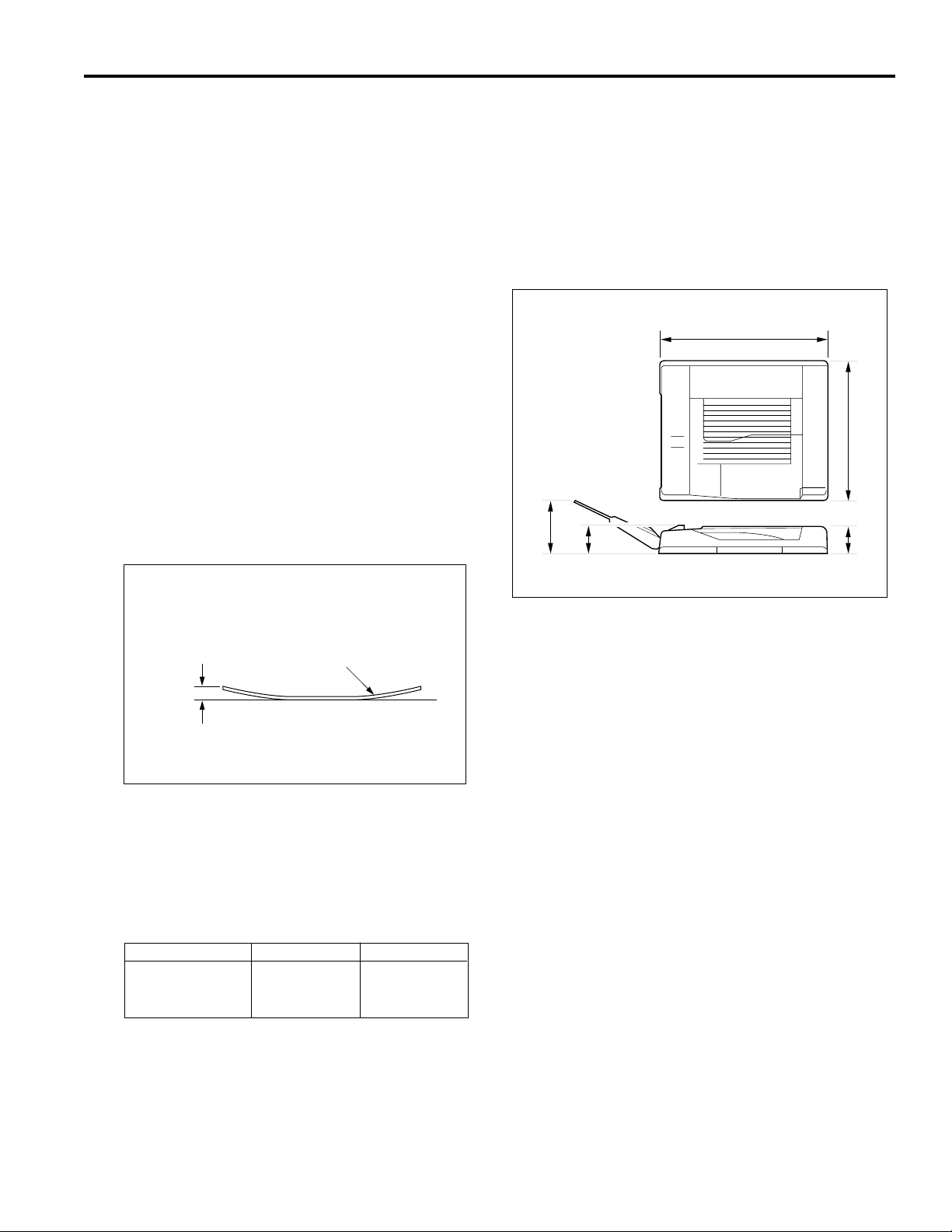
Machine dimensions:
24.3
7.6
4
20.6
3.9
inches
Original
Curling
Original curling: Max 10 mm
Max number of
Stacked originals: 50 (22 lb.)
Original conveyance speed
Mode
One-sided original
to
One-sided copy
:
Original size
8.5x11
4. Maintenance
Maintenance: Same as the main body
5. Operating Environment
Temperature: 50°F to 91°F
Humidity: 20% to 80%RH
Note: The contents of this manual may be changed without
prior notice for the sake of improvement.
Feed speed
60sheets/
minute
1
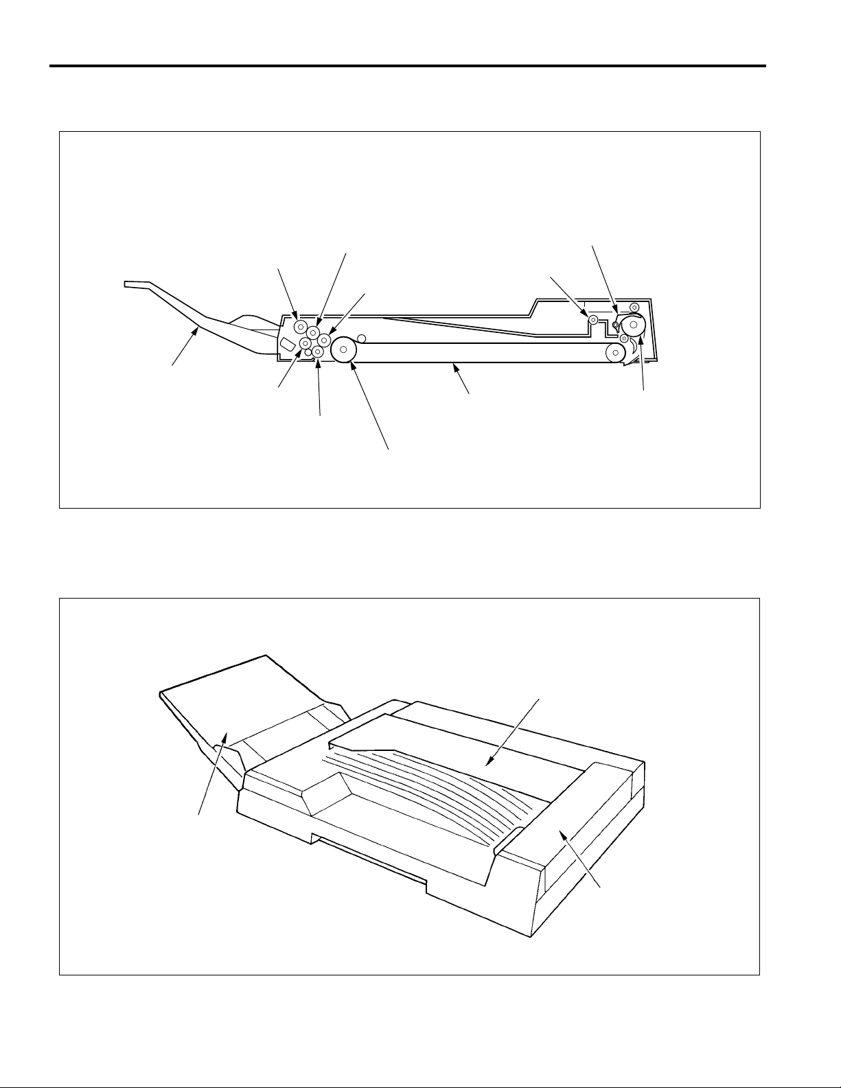
CENTER CROSS-SECTIONAL DRAWING
Original
paper feed
tray
EXTERNALS
Paper feed
roller
Double feed
prevention
roller
Feed roller
Resistration
driven roller
Resistration drive
roller
Conveyance belt
Drive roller
Switching guide
Paper exit roller
Conveyance roller
Original paper
feed tray
Original protection cover
Paper exit cover
2
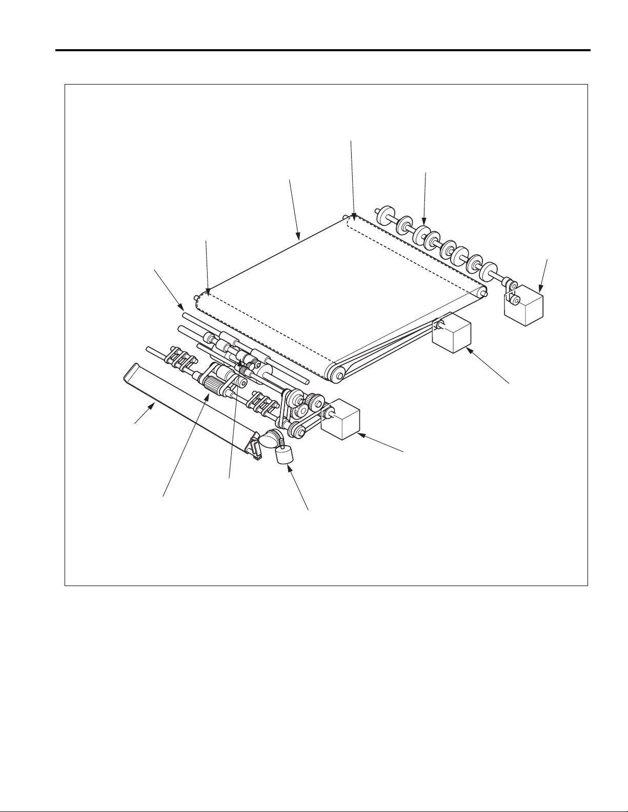
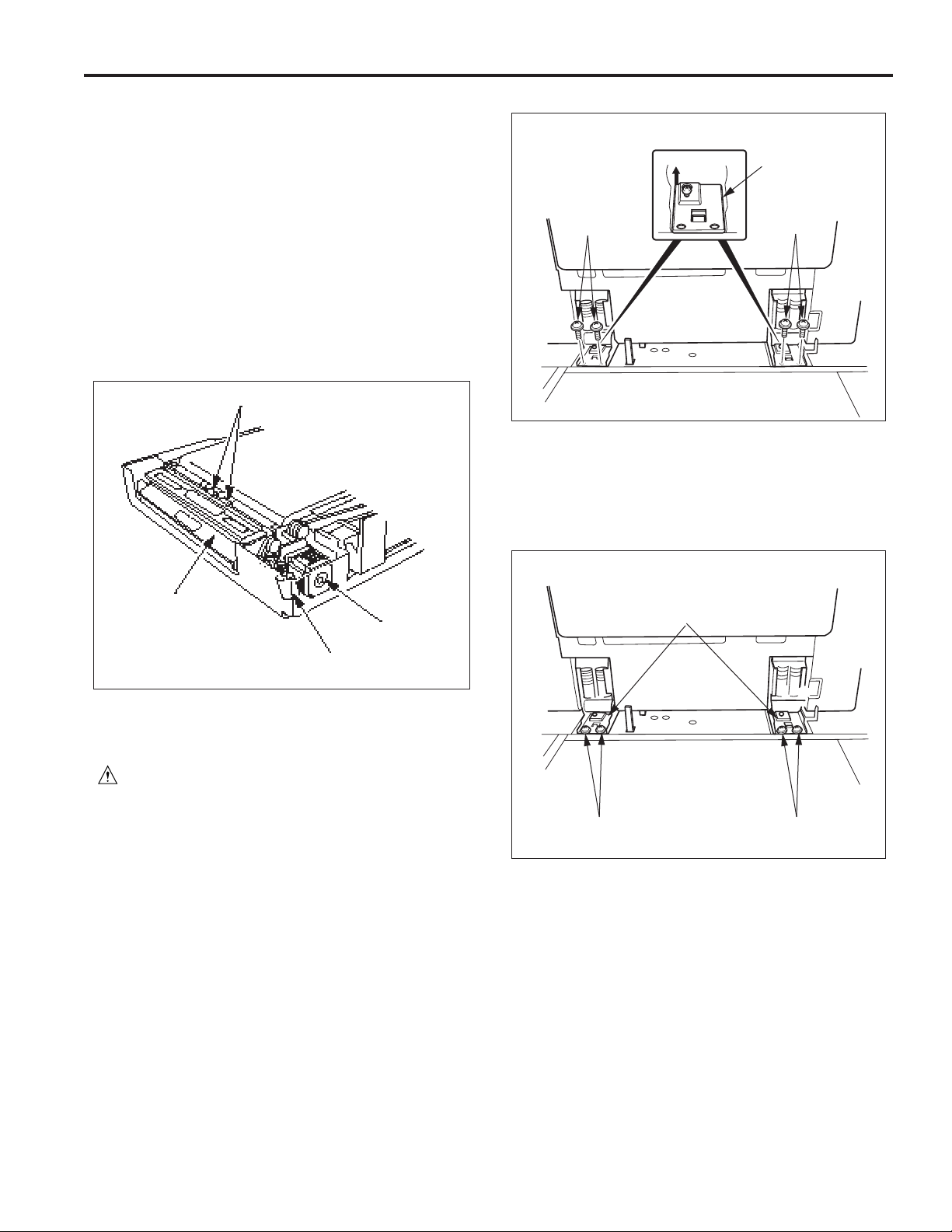
DRIVE SECTION
DF-310
Driven roller
Regist drive roller
Original push
pressure plate
Drive roller
Conveyance belt
Conveyance roller
Paper exit motor
(M303)
Conveyance motor
(M302)
Paper feed motor
(M301)
Feed roller
Double feed
prevention roller
Push pressure motor
(M304)
3
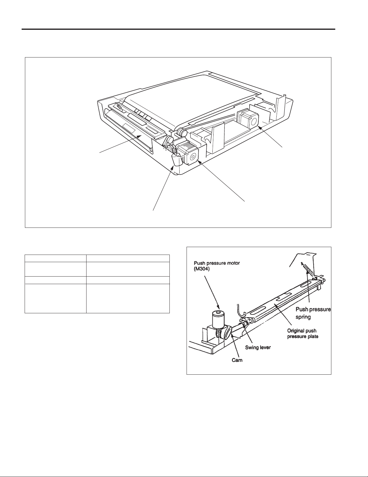
PAPER FEED SECTION
Composition
Original push
pressure plate
Push pressure motor (M304)
Mechanisms
Mechanism Method
Paper feed Stack automatic feed (upward
feed)
Double feed prevention Double feed prevention roller
Original size detection Original passage time detection
method
(Size detected by the number of
count pulses from PS302.)
Conveyance motor
(M302)
Drive motor (M301)
Paper Feed Drive Section
The drive section performs the following kinds of control when
originals are being fed.
Original push pressure plate pressing and release
operations
The drive force from the push pressure motor (M304) is
transferred to the swing lever via the lifting cam.
The swing lever is mounted on the original push pressure plate.
The drive force from the swing lever causes the original push
pressure plate to move up and down. As a result, the original
push pressure plate alternately pushes against and separates
from the original in the original paper feed tray. The push
pressure spring maintains the paper feed pressure constant.
4
Control of the paper feed roller
The paper feed roller is controlled by the paper feed motor
(M301).
When the paper feed motor rotates in the forward direction, the
drive force is transmitted to the paper feed roller and the feed
roller via the paper feed drive shaft, causing pre-paper feed to
take place.
Control of the resistration roller
The resistration roller is controlled by the paper feed roller
(M301). When pre-paper feed takes place, the paper feed
roller rotates in reverse, and the drive force is transmitted to the
resistration drive roller and the resistration driven roller via the
resistration drive roller shaft, causing paper feed to take place.
Resistration driven roller
Hinge retaining
plate
Set screws
Set screws
(6) Reinstall the above parts in the opposite sequence to
removal.
Adjustment
(1) Loosen the four set screws of the hinge retaining plate.
DF-310
Original push
pressure plarte
Push pressure
motor (M034)
Paper feed
motor (M301)
Disassembly and Reassembly
Removing and Reinstalling the ADF
Caution: Be sure that the power cord has been
unplugged from the power outlet.
Procedure
(1) Remove the rear main body cover.
(2) Disconnect the ADF connector (CN102) from the back
of the machine.
(3) Remove the set screw, then remove the original paper
feed tray.
(4) Open the ADF 90°, then remove the two set screws
from each of the left and right hinges.
(5) Remove the hinge retaining plate, then remove the
ADF.
Set screws
Hinge retaining plates
Set screws
5
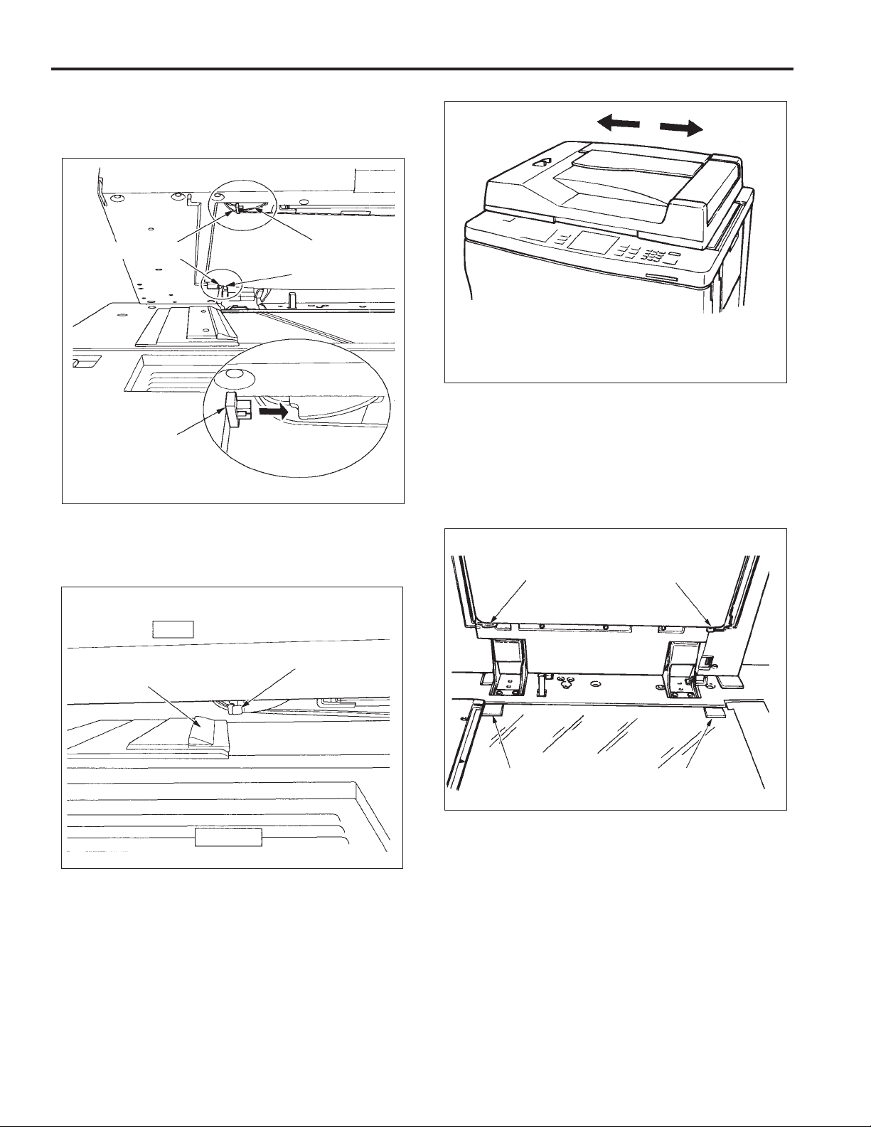
(2) Open the RADF unit and set the two jig (ADF positioning
block) to the positioning piece (front, rear).
ADF
positioning
blocks
ADF
positioning
block
Positioning
piece
(front,rear)
(3) Close the RADF unit slowly and move the RADF unit
right and left, until the jig comes into contact with the
end of the scale plate.
RADF
(4) Oplen the RADF unit slowly and tighten the four set
screws of the hinge retaining plate after removing the
jig.
(5) When the RADF unit is closed, place the two jig
(spacer/A) onto the platen glass opposite to the
positioning piece (rear) and the protrusion (rear).
Positioning
piece (rear)
Protrusion (rear)
Scale plate
Front of main
body
ADF positioning
block
Jig (spacer/A)
Jig (spacer/A)
6
DF-310
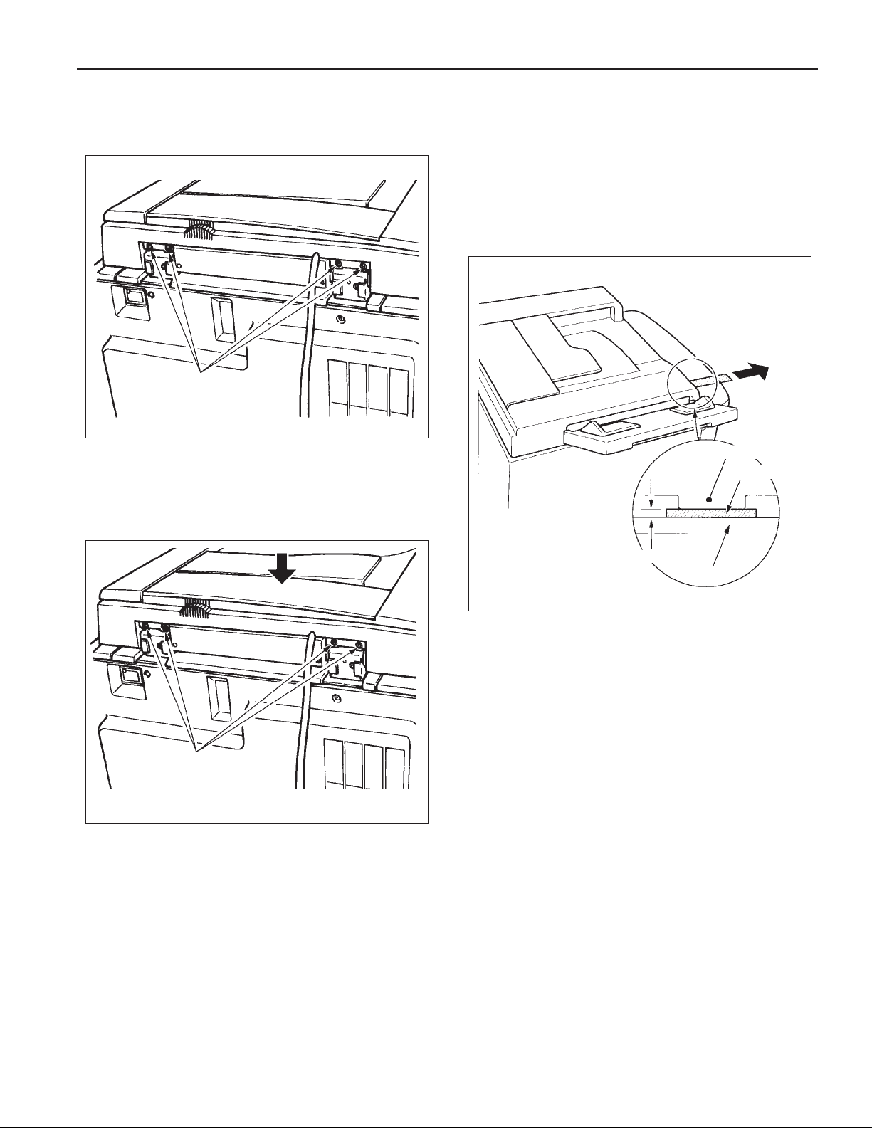
(6) Close the RADF unit slowly.
(7) Loosen the four height adjustment screws.
Height adjustment
screws
(8) Tighten the four height adjustment screws in a state
that press the RDF unit down, and the positoning piece
(rear) and the protrusion (rear) comes to the end of the
jig.
Check
Clearance between position piece (left side - front)
and platen glass of the RADF unit.
Standard: less than 0.1mm
(1) Put the two sheet of the copy paper (80g/m
2
x 20mm) between positioning piece (left side - front)
and, and pull them.
(2) If they are pull lightly, since the clearance is too big,
readjust the height.
Positioning piece (left side - front)
Copy paper
, 200mm
Height adjustment
screw
(9) Open the RADF unit and remove the jig.
Less than 0.1mm
Platen glass
Clearance between the platen glass and the protrusion
(right side - front) of the RADF unit.
Standard: less than 0.6mm
(1) Check that the clearance is less than 0.6 mm with a
visual inspection.
7
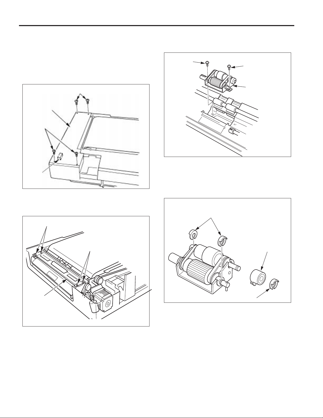
Replacing the Paper Feed Rubber and Feed
Rubber
Procedure
(1) Remove the four set screws, then remove main body
base plate (A).
(2) Disconnect the relay connector.
(4) Remove the two set screws and remove the feed roller
assembly.
Set screw
Set screw
Set screws
Main body
base plate (A)
Set screws
Relay
connector
(3) Remove the four set screws and remove the paper
feed guide plate (lower) assembly.
Set screws
Feed roller
assembly
(5) Remove the stop ring, then remove the one-way clutch.
(6) Remove the two stop rings.
Stop rings
Paper feed
guide plate
(lower)
assembly
Set screws
one-way clutch
Stop ring
8
 Loading...