

Konica Minolta DF-217 User Manual

SERVICE MANUAL
Model
DF-217
Used on models 7115/7118
DECEMBER 2001
CSM-DF217
KONICA BUSINESS TECHNOLOGIES, INC.


DF-217
SERVICE MANUAL
DECEMBER 2001
Used on Konica Models
7115/7118

IMPORTANT NOTICE
Because of the possible hazards to an inexperienced
person servicing this equipment, as well as the risk of
damage to the equipment, Konica Business Technologies strongly recommends that all servicing be performed by Konica-trained service technicians only.
Changes may have been made to this equipment to
improve its performance after this service manual was
printed. Accordingly, Konica Business Technologies,
Inc., makes no representations or warranties, either
expressed or implied, that the information contained in
this service manual is complete or accurate. It is understood that the user of this manual must assume all risks
or personal injury and/or damage to the equipment while
servicing the equipment for which this service manual
is intended.
Corporate Publications Department
© 2001, KONICA BUSINESS TECHNOLOGIES, INC.
All rights reserved.
Printed in U.S.A.

CONTENTS
GENERAL, MECHANICAL/ELECTRICAL
1. SPECIFICATIO NS .............. ........... ................ ............... ............... ............... ..... M-1
2. EXTERIOR VIEW ................................................. ...........................................M-2
3. CROSS-SEC TION AL VIEW .............. ............... ................ ............... ............... .M-3
4. DRIVE SYSTEM ..............................................................................................M-4
5. ELECTRICAL COMPONENT LAYOUT ...........................................................M-5
6. MODES ........ .... ....... ........ ........ ....... ........ .... ....... ........ ........ ....... ........ ........ ... .....M-6
6-1. Standard M od e ........... ............... ............... ................ ............... ............... .M-6
6-2. Mixed Origin al D et ection Mode ..................... ................ ... ................ ........M -6
7. TAKE-UP SECTION ........................................................................................M-7
7-1. Document Take-U p and Fee d Mec ha ni sm ........... .... .... ............... .... ........M- 7
7-2. Document Separating Mechanism ...........................................................M-8
8. TRANSPORT/EXIT MECHANISM ...................................................................M-9
8-1. Document Transport Mechanism .............................................................M-9
8-2. Document Exit Mechanism ......................................................................M-10
9. OTHER FEATURES ........................................................................................M-11
9-1. Document Size Det ectio n M echa ni sm ... ............... .... ............... ............... .M-11
9-2. Raised/Lowered Position Detection Mechanism .....................................M-11
DIS/REASSEMBLY, ADJUSTMENT
1. MAINTENANCE SCHEDULE ..........................................................................D-1
2. DISASSEMBLY ...............................................................................................D-2
2-1. Removal of the Exterior Covers ...............................................................D-2
2-2. Removal of the Pi ck -U p Rol ler/Take-Up R o lle r ........ ............... ................D-3
2-3. Removal of the Separator Roller .............................................................D-4
2-4. Cleaning of the Registration R o lle r /Rolls .......... ............... ................ ........D-4
2-5. Cleaning of the Exit Roller/Rolls ..............................................................D-5
3. ADJUSTMENT ............ .... ............... .... .... ............... .... ............... .... ............... .... .D-6
3-1. Adjust Mode Se tti ng Pr o c ed ure .................... ................ ............... ............D-6
3-2. Height Adjustment ...................................................................................D-6
3-3. Leading Edge Skew Adjustment ..............................................................D-7
3-4. Zoom Adju st me nt an d R eg is tra tion Adjustm e nt ........... ............... ............D-8
(1) FD Zoom Ratio Adjus tm e nt ....... .... ... ................ .... ............... .... ........D-8
(2) CD Registration Adjustment ............................................................D-9
(3) FD Registration Adjustme nt .......................... ...................................D - 10
TECH. REP. MODE
1. TECH. REP. M OD E .... .... ............... .... ............... .... ................ ... ................ ... .....S-1
1-1. Tech. Rep. Mode Setting Procedure .......................................................S-1
1-2. ADF Document Passage Test .................................................................S-1
1-3. ADF Original Glass Check .......................................................................S-1
TROUBLESHOOTING
1. MISFEED DETECTION TIMING AND MISFEED TROUBLESHOOTING
PROCEDURES ...............................................................................................T-1
1-1. Misfeed Dete ctio n Tim in g ...................... ............... .... ............... ............... .T-1
1-2. Misfeed Troub les h ootin g Proc e du res ............... .... .... .... ... ................ ... .....T-2
iii

iv

SAFETY PRECAUTIONS
SAFETY PRECAUTIONS
Installation Environment
Safety considerations usually are directed toward
machine design and the possibility of human error. In
addition, the environment in which a machine is operated must not be overlooked as a potential safety
hazard.
Most electrical equipment is safe when installed in a
normal environment. However, if the environment is
different from what most people consider to be normal, it is conceivable that the combination of the
machine and the room air could present a hazardous
combination. This is because heat (such as from
fusing units) and electrical arcs (which can occur
inside switches) have the ability to ignite flammable
substances, including air.
When installing a machine, check to see if there
is anything nearby which suggests that a potential hazard might exist. For example, a laboratory
might use organic compounds which, when they
evaporate, make the room air volatile. Potentially dangerous conditions might be seen or smelled. The
presence of substances such as cleaners, paint thinners, gasoline, alcohol, solvents, explosives, or similar items should be cause for concern.
If conditions such as these exist, take appropriate
action, such as one of the following suggestions.
know what effect may be caused by altering any
aspect of the machine’s design. Such changes have
the potential of degrading product performance and
reducing safety margins.
For these reasons, installation of any modification not
specifically authorized by Konica Business Machines
U.S.A., Inc., is strictly prohibited.
The following list of prohibited actions is not all-inclusive, but demonstrates the intent of this policy.
• Using an extension cord or any unauthorized
power cord adapter.
• Installing any fuse whose rating and physical size
differs from that originally installed.
• Using wire, paper clips, solder, etc., to replace or
eliminate any fuse (including temperature fuses).
• Removing (except for replacement) any air filter.
• Defeating the operation of relays by any means
(such as wedging paper between contacts).
• Causing the machine to operate in a fashion other
than as it was designed.
• Making any change which might have a chance
of defeating built-in safety features.
• Using any unspecified replacement parts.
• Determine that the environment is controlled
(such as through the use of an exhaust hood) so
that an offending substance or its fumes cannot
reach the machine.
• Remove the offending substance.
• Install the machine in a different location.
The specific remedy will vary from site to site, but the
principles remain the same. To avoid the risk of injury
or damage, be alert for changes in the environment
when performing subsequent service on any machine, and take appropriate action.
Unauthorized Modifications
Konica equipment has gained a reputation for being
reliable products. This has been attained by a combination of outstanding design and a knowledgeable
service force.
The design of the equipment is extremely important.
It is the design process that determines tolerances
and safety margins for mechanical, electrical, and
electronic aspects. It is not reasonable to expect
individuals not involved in product engineering to
General Safety Guidelines
This equipment has been examined in accordance
with the laws pertaining to various product safety
regulations prior to leaving the manufacturing facility
to protect the operators and service personnel from
injury. However, as with any operating device, components will break down through the wear-and-tear of
everyday use, as will additional safety discrepancies
be discovered. For this reason, it is important that the
technician periodically performs safety checks on the
equipment to maintain optimum reliability and safety.
The following checks, not all-inclusive, should be
made during each service call:
CAUTION: Avoid injury. Ensure that the equipment is
disconnected from its power source before continuing.
• Look for sharp edges, burrs, and damage on all
external covers and copier frame.
• Inspect all cover hinges for wear (loose or bro-
ken).
• Inspect cables for wear, frays, or pinched areas.
v

SAFETY PRECAUTIONS
• Ensure that the power cord insulation is not dam-
aged (no exposed electrical conductors).
• Ensure that the power cord is properly mounted
to the frame by cord clamps.
• Check the continuity from the round lug (GND) of
the power cord to the frame of the copier -- ensure
continuity. An improperly grounded machine can
cause an electrically-charged machine frame.
Safeguards During Service Calls
Confirm that all screws, parts, and wiring which are
removed during maintenance are installed in their
original positions.
• When disconnecting connectors, do not pull the
wiring, particularly on AC line wiring and high
voltage parts.
• Do not route the power cord where it is likely to
be stepped on or crushed.
• Carefully remove all toner and dirt adhering to any
electrical units or electrodes.
• After part replacement or repair work, route the
wiring in such a way that it does not contact any
burrs or sharp edges.
• Do not make any adjustments outside of the
specified range.
Applying Isopropyl Alcohol
Care should be exercised when using isopropyl alcohol, due to its flammability. When using alcohol to
clean parts, observe the following precautions:
• Remove power from the equipment.
• Use alcohol in small quantities to avoid spillage
or puddling. Any spillage should be cleaned up
with rags and disposed of properly.
• Be sure that there is adequate ventilation.
• Allow a surface which has been in contact with
alcohol to dry for a few minutes to ensure that the
alcohol has evaporated completely before applying power or installing covers.
Summary
It is the responsibility of every technician to use professional skills when servicing Konica products. There
are no short cuts to high-quality service. Each piece
of equipment must be thoroughly inspected with respect to safety considerations as part of every routine
service call. The operability of the copier, and more
importantly, the safety of those who operate or service
the equipment, are directly dependent upon the conscientious effort of each and every technician.
Remember...when performing service calls, use good
judgment (have a watchful eye) to identify safety
hazards or potential safety hazards that may be present, and correct these problem areas as they are
identified -- the safety of those who operate the equipment as well as those who service the copier depend
on it!
vi

GENERAL,
MECHAN ICAL/ELECTRICAL

1. SPECIFICATIONS
Name : Automatic Document Feeder
Installation : Inserted in top portion in the rear of copier
Type of Do cume n t :
Detectable Document
Size
Capacity :
Document Alignment : Center
Document Loading : Face up
Document Exchan ge
Speed
Modes : Standard
Power Require m en ts : DC24 V, DC5 V (suppl ie d f rom t he c op ier)
Max. Power Consumption : 36 W or less
Dimensions : Width: 602 mm or 23-3/4
Weight : 5.5 kg or 12-1/4 lbs.
Operati n g E nv ir o nment : Same as copier
Type of Originals Not
Guaran teed for Reliable
Feeding
Plain pa pe r (Sta ndar d : 50 to 11 0g/m
Mixed Original: 60 to 90 g/m
: Metric Areas:A5R, B5/B5R, A4/A4R, B4R, A3R, 11 × 8-1/2,
Inch Areas:5-1/2 × 8-1/2R, 11 × 8-1/2, 8-1/2 × 11R,
50 sheets max. (80 g/m
: 15 sheets/min. (A4)
18 sheets/min. (A4)
Mixed Original (only for originals with the same width)
Depth: 502 mm or 19-3/4
Height: 101 mm or 4
8-1/2 × 11R, F4
8-1/2 × 14R, 11 × 15, 11 × 17
2
)
2
or 13-1 / 4 to 29 - 1/4 l bs . ,
2
or 16 to 24 lbs.)
Type of Original Possible Trouble
Sheets stapled or clipped together Take-up failure, damaged sheet, defective
drive mechanism due to jammed staples or
clips.
Sheets glued toget her Ta ke-up f ailure, dama ged sheet
Sheets folded, torn, or wrinkled Ta ke-up failure, damaged sheet
Sheets severely curled Sheets misfeed due to being dog-eared or
fed in askew
M-1
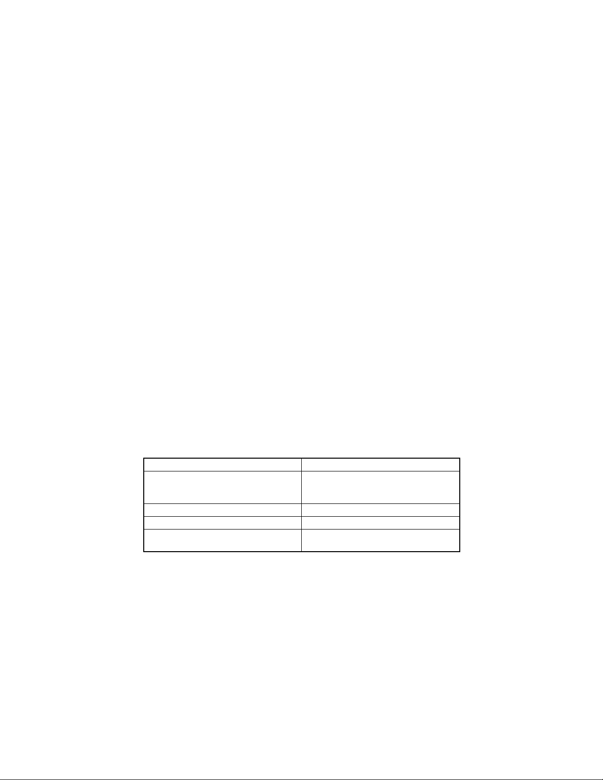
2. EXTERIOR VIEW
12
4
1. Take-Up C ove r 3. Doc um e nt Loading Tray
2. Rear Cover 4. Document Edge Guide
3
4688M507CA
M-2
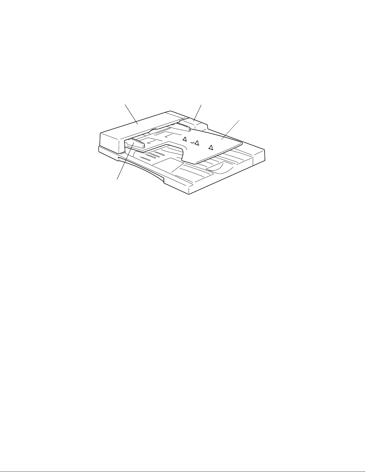
3. CROSS-SECTIONAL VIEW
12 3
8
7
456
1. Take-Up Roller 5. Registration Rollers
2. Pick-Up Roller 6. Registration Rolls
3. Exit Rollers 7. Transport Rolls
4. Exit Ro lls 8. Separat or Roller
4688M504CA
M-3
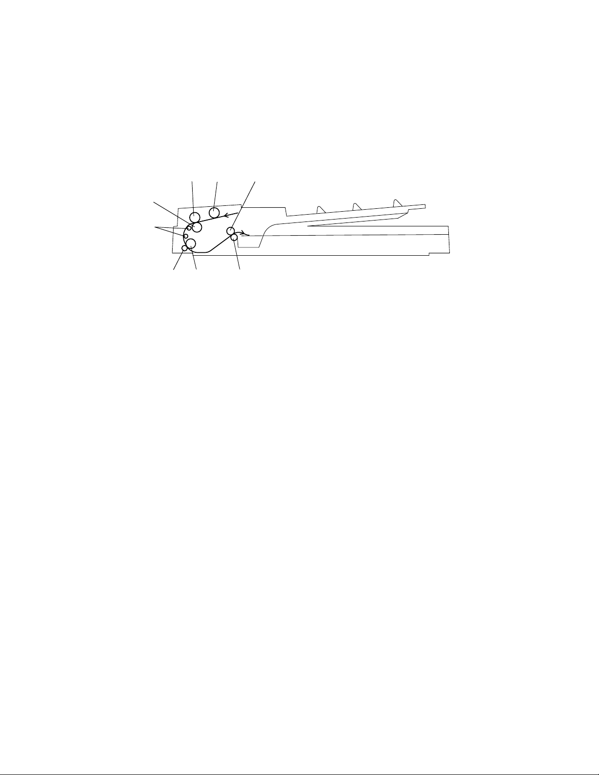
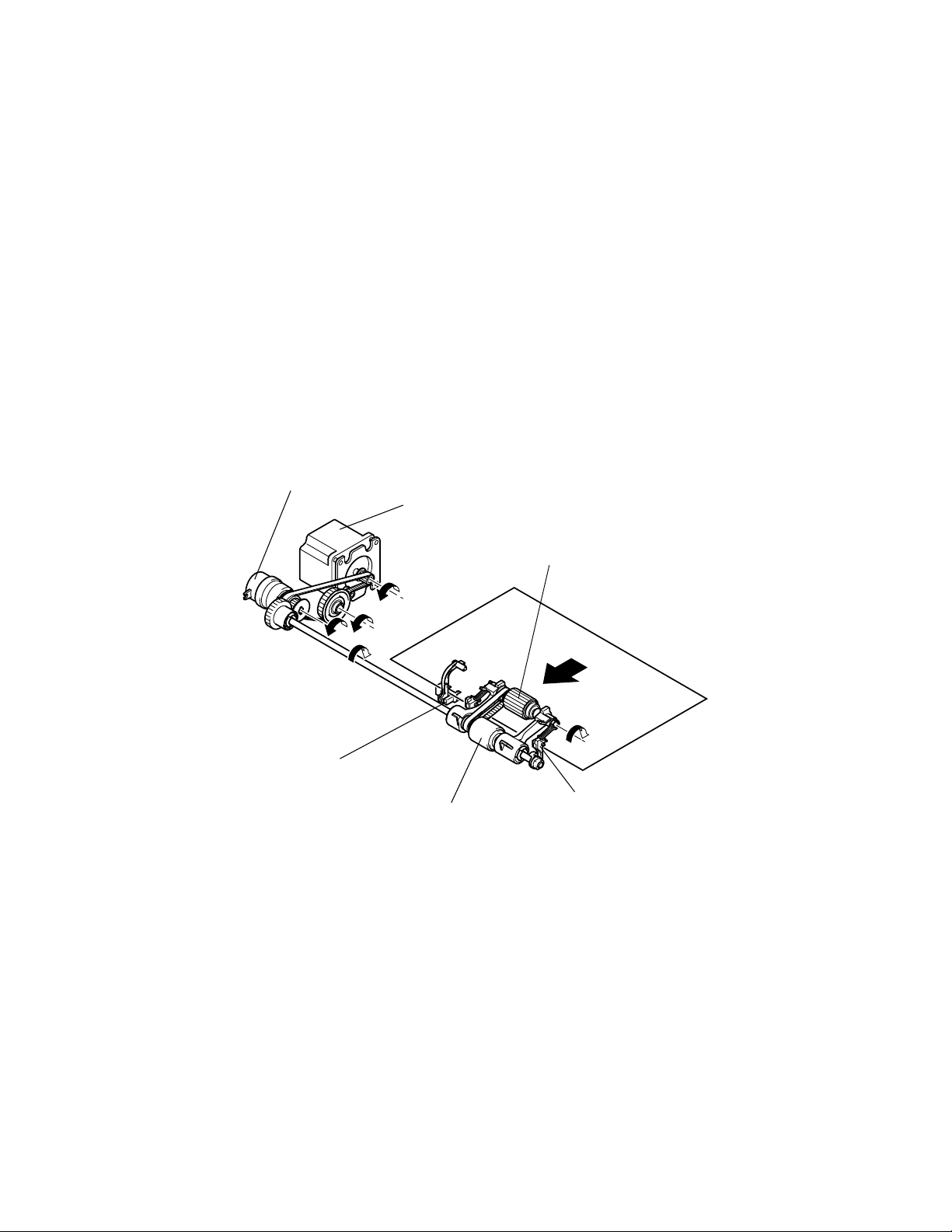
4. DRIVE SYSTEM
1
6
5
4
1. Main M o t or 4. Reg is tr ati on Roll ers
2. Pick-Up Roller 5. Take-Up Roller
3. Exit Rollers 6. Take-Up Clutch
2
3
4688M502AA
M-4
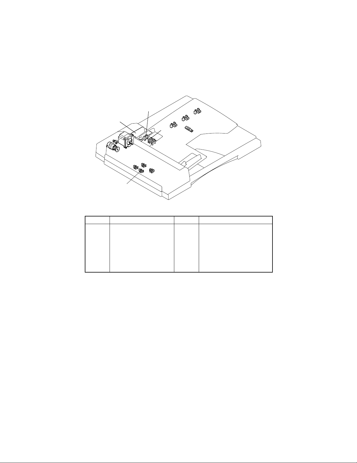
5. ELECTRICAL COMPONENT LAYOUT
PC12
PWB
PC1
CL1
PC2
PC4
PC3
Symbol Name Symbol Name
PWB
CL1
PC1
PC2
PC3
PC4
✽ PC9: In ch area only
✽ PC10: Metric area only
Interface Board
Main Motor
M1
Paper Take-Up Clutch
Take-Up Cover Open/Close
Detecting Sensor
Paper Empty Sensor
Registration S ensor
Separator Sensor
PC6
PC11
PC10
PC5
PC8
PC5
PC6
PC7
PC8
PC9
PC10
PC11
PC12
PC9
PC7
Paper Exit Sensor
Length Si ze D etection Se n s or 1
Length Si ze D etection Se n s or 2
Length Si ze D etection Se n s or 3
Length Si ze D etection Se n s or 4
Width S ize D etection Sensor 1
Width S ize D etection Sensor 2
Width S ize D etection Sensor 3
4688M505CA
M-5

6. MODES
6-1. Standard Mode
• When a multi-page document is being copied, the copier detects the size of only the first
page of the document and copies the subsequent pages based on that size detection.
• This saves the copier th e t ime required for detecting the sizes of the subsequent pages
of the document, making for faster paper feed timing.
6-2. Mixed Original Detection Mode
• The copier detec t s t he si ze of each pag e of the docu ment and, according to th e size
detected, feeds the paper of the corresp onding s ize selec ted from a m ong the avai labl e
paper sources for making copies.
• This mode is used when making copies from a document set consistin g of pages of varying leng th, but of th e sa me width.
M-6
7. TAKE-UP SECTION
7-1. Document Take-Up and Feed Mechanism
• The document is taken up as the Pick-Up Roller and Take-Up Roller turn.
• The Pick-Up R oller tran s port s the docu ment up to the Take-Up Roller.
• After a scan is completed, the Main Motor is turned backward to raise the Pick-Up Roller.
• The Pick-U p Roller an d the Take-Up R olle r are tu rned thro ug h th e P ap er Take-U p Clu t ch
and by a gear train and a belt driven by the Main Motor.
• The Paper Empty Sensor is used to detect a document loaded on the Document Loading
Tray.
• The Document Stoppers determine the leading edge position of the document loaded on
the Document Loading Tray. They are in the lowered, swung-down position in the standby
state and swing upward w he n the docu m en t is to be taken up.
• The swing-up and swing-down motion of the Document Stoppers is operatively connected to the r ai si ng and lowering of the Pic k- Up Roller.
Paper Take-Up Clutch CL1
Main Motor M1
Pick-Up Roller
Paper Empty Sensor PC2
Ta ke-Up Roller
M-7
Document Stoppers
4688M005AA
7-2. Document Separating Mechanism
• The coeffic ie nt of fr ic tion betw ee n the Take-Up Roller and S ep arator Rol le r i s effec tive ly
used to prevent double feed of paper.
When on e sh ee t
of paper is take n
up
When tw o or mor e
shee ts of paper
are taken up
Ta ke-Up Roller
: The coefficient of f riction on the front sid e of the shee t of paper
taken up and fed through the space between the Take-Up Roller
and Separator Rolle r is th e sa me as that on th e backside of t h e
sheet of paper, allowing the paper to be properly fed into the
copier.
: The coefficient of friction between the paper and the Separator
Roller is greater than that betwe en the shee ts of paper, which
allows only the top sheet of paper to be fed into the copier.
Separator Roller
4688M006AA
M-8
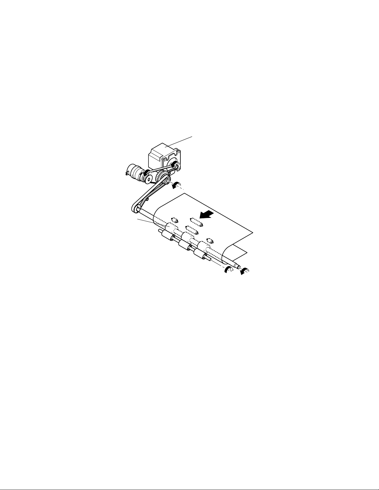
8. TRANSPORT/EXIT MECHANISM
8-1. Document Transport Mechanis m
• The document taken up is tran sported to the do cument scanning position of the copier by
the Reg is trat i on R o ll er s.
• The Registration Ro ll ers a r e tur ned by a ge ar trai n and be lt s which are drive n by the
Main Motor.
Main Motor M1
Registration Rollers
M-9
4688M007AA
 Loading...