

Page 1

SERVICE MANUAL
Model
DB-208/608
SECOND EDITION
NOVEMBER 2000
CSM-DB208/608
KONICA BUSINESS TECHNOLOGIES, INC.
Page 2

Page 3

DB-208/608
SERVICE MANUAL
NOVEMBER 2000
SECOND EDITION
Page 4

IMPORTANT NOTICE
Because of the possible hazards to an inexperienced
person servicing this equipment, as well as the risk of
damage to the equipment, Konica Business Technologies strongly recommends that all servicing be performed by Konica-trained service technicians only.
Changes may have been made to this equipment to
improve its performance after this service manual was
printed. Accordingly, Konica Business Technologies,
Inc., makes no representations or warranties, either
expressed or implied, that the information contained in
this service manual is complete or accurate. It is understood that the user of this manual must assume all risks
or personal injury and/or damage to the equipment while
servicing the equipment for which this service manual
is intended.
Corporate Publications Department
© 2000, KONICA BUSINESS TECHNOLOGIES, INC.
All rights reserved.
Printed in U.S.A.
Page 5

CONTENTS
DB-208 OUTLINE
DB-208 PRODUCT SPECIFICATIONS.........................1-1
CENTER CROSS-SECTIONAL VIEW ..........................1-2
DRIVE SYSTEM DIAGRAM ..........................................1-2
DB-208 UNIT EXPLANATION
PAPER FEED UNIT ...................................................... 1-3
COMPOSITION .............................................................1-3
Mechanisms ........................................................... 1-3
Paper Feed and No-Paper Detection Control........ 1-4
Tray Up Control......................................................1-6
Paper Size Detection Control ................................ 1-8
DB-208 DISASSEMBLY/ASSEMBLY
DISASSEMBLY AND REASSEMBLY ........................... 1-9
Removing and Reinstalling the Paper
Feed Tray............................................................ 1-9
Removing and Reinstalling the Paper Feed
Unit...................................................................... 1-9
Replacing the Separation Rubber and the Paper
Supply Rubber ..................................................... 1-10
Removing and Reinstalling the Double-Feed
Prevention Roller ..............................................1-10
CONTENTS
Removing and Reinstalling the Paper Feed
Tray (LCT).........................................................2-15
Removing and Reinstalling the Front Tray
Cover (LCT) ......................................................2-15
Replacing the Up/Down Wires.............................2-16
DB-208/608 DIAGRAMS
ELECTRICAL PARTS LAYOUT ....................................3-1
CONNECTOR LAYOUT ................................................3-2
DB-208 OVERALL WIRING DIAGRAM ........................3-3
DB-608 OVERALL WIRING DIAGRAM ........................3-4
DB-608 OUTLINE
DB-608 PRODUCT SPECIFICATIONS.........................2-1
CENTER CROSS-SECTIONAL VIEW ..........................2-2
DRIVE SYSTEM DIAGRAM ..........................................2-2
DB-608 UNIT EXPLANATION
500-SHEET PAPER TRAY UNIT ..................................2-3
Composition ...........................................................2-3
Mechanisms ...........................................................2-3
500-Sheet Paper Feed Tray and No-Paper
Detection Control ................................................2-4
Tray-Up Control (PFU)...........................................2-6
Paper Size Detection Control ................................2-7
1500-SHEET PAPER TRAY UNIT ................................2-8
Composition ...........................................................2-8
Mechanisms ...........................................................2-8
1500-Sheet Paper Feed Tray and No-Paper
Detection Control ................................................2-9
Tray-Up Control (LCT) .........................................2-11
DB-608 DISASSEMBLY/ASSEMBLY
DISASSEMBLY AND REASSEMBLY .........................2-12
Removing the Reinstalling the Paper Feed
Tray ...................................................................2-12
Removing and Reinstalling the Paper Feed
Unit....................................................................2-12
Replacing the Separation Rubber and the Paper
Supply Rubber ..................................................2-13
Removing and Reinstalling the Double-Feed
Prevention Roller ..............................................2-14
iii
Page 6

CONTENTS
This page left blank intentionally.
iv
Page 7

SAFETY PRECAUTIONS
SAFETY PRECAUTIONS
Installation Environment
Safety considerations usually are directed toward
machine design and the possibility of human error. In
addition, the environment in which a machine is operated must not be overlooked as a potential safety
hazard.
Most electrical equipment is safe when installed in a
normal environment. However, if the environment is
different from what most people consider to be normal, it is conceivable that the combination of the
machine and the room air could present a hazardous
combination. This is because heat (such as from
fusing units) and electrical arcs (which can occur
inside switches) have the ability to ignite flammable
substances, including air.
When installing a machine, check to see if there
is anything nearby which suggests that a potential hazard might exist. For example, a laboratory
might use organic compounds which, when they
evaporate, make the room air volatile. Potentially dangerous conditions might be seen or smelled. The
presence of substances such as cleaners, paint thinners, gasoline, alcohol, solvents, explosives, or similar items should be cause for concern.
If conditions such as these exist, take appropriate
action, such as one of the following suggestions.
effect may be caused by altering any aspect of the
machine’s design. Such changes have the potential
of degrading product performance and reducing
safety margins.
For these reasons, installation of any modification not
specifically authorized by Konica Business Machines
U.S.A., Inc., is strictly prohibited.
The following list of prohibited actions is not all-inclusive, but demonstrates the intent of this policy.
• Using an extension cord or any unauthorized
power cord adapter.
• Installing any fuse whose rating and physical size
differs from that originally installed.
• Using wire, paper clips, solder, etc., to replace or
eliminate any fuse (including temperature fuses).
• Removing (except for replacement) any air filter.
• Defeating the operation of relays by any means
(such as wedging paper between contacts).
• Causing the machine to operate in a fashion other
than as it was designed.
• Making any change which might have a chance
of defeating built-in safety features.
• Using any unspecified replacement parts.
• Determine that the environment is controlled
(such as through the use of an exhaust hood) so
that an offending substance or its fumes cannot
reach the machine.
• Remove the offending substance.
• Install the machine in a different location.
The specific remedy will vary from site to site, but the
principles remain the same. To avoid the risk of injury
or damage, be alert for changes in the environment
when performing subsequent service on any machine, and take appropriate action.
Unauthorized Modifications
Konica copiers have gained a reputation for being
reliable products. This has been attained by a combination of outstanding design and a knowledgeable
service force.
The design of the copier is extremely important. It is
the design process that determines tolerances and
safety margins for mechanical, electrical, and electronic aspects. It is not reasonable to expect individuals not involved in product engineering to know what
General Safety Guidelines
This copier has been examined in accordance with
the laws pertaining to various product safety regulations prior to leaving the manufacturing facility to
protect the operators and service personnel from
injury. However, as with any operating device, components will break down through the wear-and-tear of
everyday use, as will additional safety discrepancies
be discovered. For this reason, it is important that the
technician periodically performs safety checks on the
copier to maintain optimum reliability and safety.
The following checks, not all-inclusive, should be
made during each service call:
CAUTION: Avoid injury. Ensure that the copier is
disconnected from its power source before continuing.
• Look for sharp edges, burrs, and damage on all
external covers and copier frame.
• Inspect all cover hinges for wear (loose or broken).
• Inspect cables for wear, frays, or pinched areas.
v
Page 8

SAFETY PRECAUTIONS
• Ensure that the power cord insulation is not damaged (no exposed electrical conductors).
• Ensure that the power cord is properly mounted
to the frame by cord clamps.
• Check the continuity from the round lug (GND) of
the power cord to the frame of the copier -- ensure
continuity. An improperly grounded machine can
cause an electrically-charged machine frame.
Safeguards During Service Calls
Confirm that all screws, parts, and wiring which are
removed during maintenance are installed in their
original positions.
• When disconnecting connectors, do not pull the
wiring, particularly on AC line wiring and high
voltage parts.
• Do not route the power cord where it is likely to
be stepped on or crushed.
• Carefully remove all toner and dirt adhering to any
electrical units or electrodes.
• After part replacement or repair work, route the
wiring in such a way that it does not contact any
burrs or sharp edges.
• Do not make any adjustments outside of the
specified range.
Applying Isopropyl Alcohol
Care should be exercised when using isopropyl alcohol, due to its flammability. When using alcohol to
clean parts, observe the following precautions:
• Remove power from the equipment.
• Use alcohol in small quantities to avoid spillage
or puddling. Any spillage should be cleaned up
with rags and disposed of properly.
• Be sure that there is adequate ventilation.
• Allow a surface which has been in contact with
alcohol to dry for a few minutes to ensure that the
alcohol has evaporated completely before applying power or installing covers.
Summary
It is the responsibility of every technician to use professional skills when servicing Konica products. There
are no short cuts to high-quality service. Each copier
must be thoroughly inspected with respect to safety
considerations as part of every routine service call.
The operability of the copier, and more importantly,
the safety of those who operate or service the copier,
are directly dependent upon the conscientious effort
of each and every technician.
Remember...when performing service calls, use good
judgement (have a watchful eye) to identify safety
hazards or potential safety hazards that may be present, and correct these problem areas as they are
identified -- the safety of those who operate the copier
as well as those who service the copier depend on it!
vi
Page 9

DB-208 PRODUCT SPECIFICATIONS
Type
Type: Paper feed tray (front loading)
Functions
Paper size: 8.5 x 11/8.5 x 11R/8.5 x 14/
11x17
Paper type: 16 lb. to 24 lb. high-quality
paper
Maximum
paper storage: 500 sheets x 3, 22 lb.
Particulars of Machine
Power: 24/5 V DC (supplied from main
body)
Power
consumption: Maximum 40 VA
Weight: Approximately 48 lb.
DB-208/608
Machine
dimensions: Width 24.0 in.
Depth 23.1 in.
Height 16.9 in.
Maintenance and Life
Maintenance: Same as the main body
Operating Environment
Temperature: 50°F to 86°F
Humidity: 10% to 80% RH
Note: These specifications are subject to change
without notice.
1-1
Page 10
DB-208/608
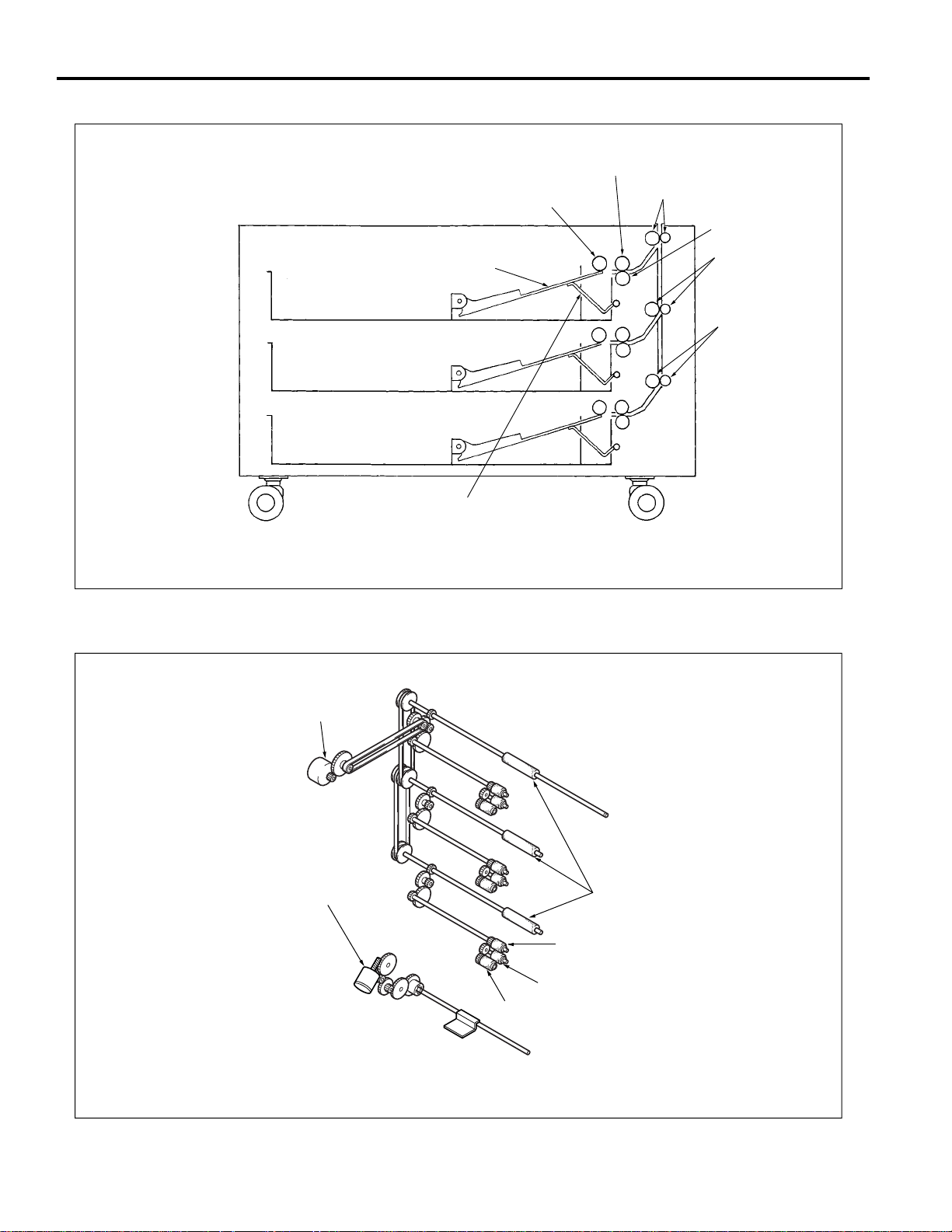
CENTER CROSS-SECTIONAL VIEW
Separation roller
Paper feed roller
Conveyance rollers (upper)
Double-feed
prevention roller
Paper lift-up plate
Paper lift-up lever
DRIVE SYSTEM DIAGRAM
Conveyance
rollers (middle)
Conveyance
rollers (lower)
Paper feed motor (M401)
Up/down motor (U) (M402)
Up/down motor (M) (M403)
Up/down motor (L) (M404)
Intermediate
conveyance rollers
Separation roller
Double-feed prevention roller
Paper feed roller
1-2
Page 11
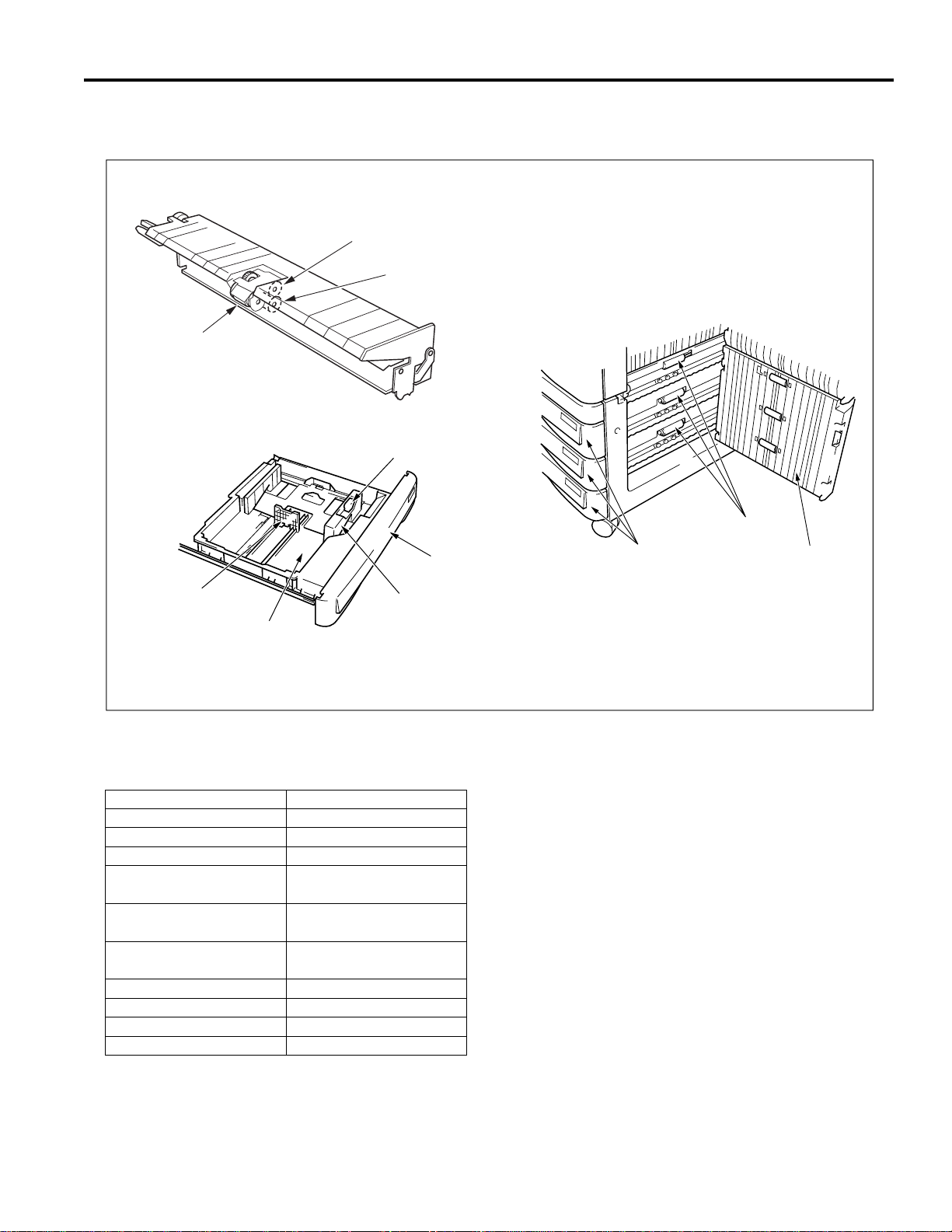
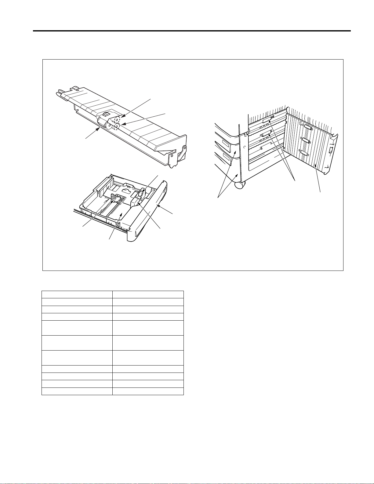
PAPER FEED UNIT
Composition
Paper feed roller
Guide release lever
DB-208/608
Separation roller
Double-feed
prevention roller
Rear edge stopper
Paper feed tray
Mechanisms
Mechanisms
Paper feed
Paper lifting
Double-feed prevention
1st paper feed
Intermediate conveyance
Paper jam handling
No-paper detection
Paper size detection
Paper conveyance
Conveyance drive
Front cover
Side guide
Method
Paper feed roller
Paper lift-up plate
Torque limiter
Separation roller, paper
feed SD
Intermediate conveyance
roller
Double-feed prevention
roller pressure release
Photosensor
Tact switch
Roller conveyance
Timing belt
Paper feed trays
Intermediate
conveyance rollers
Paper feed door
1-3
Page 12
DB-208/608
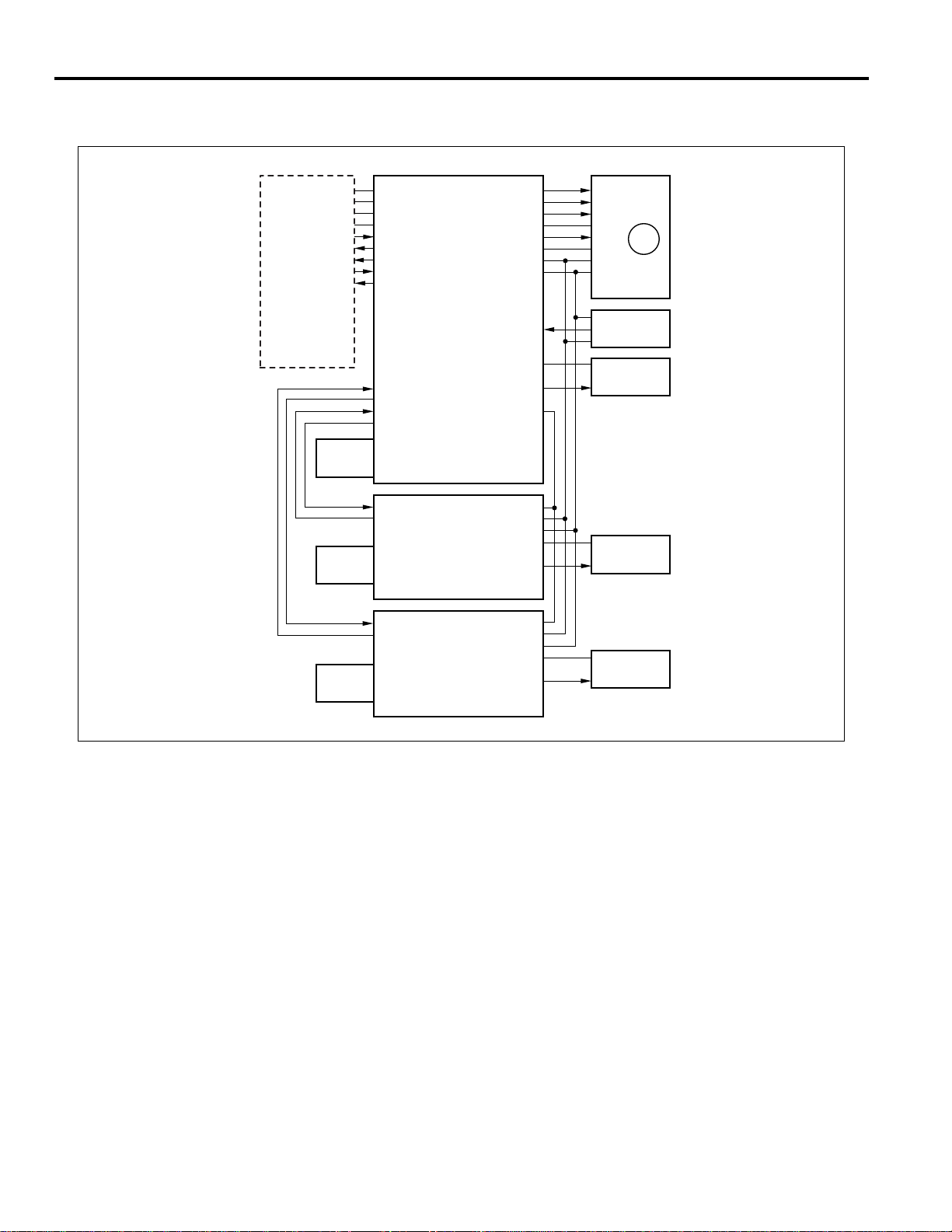
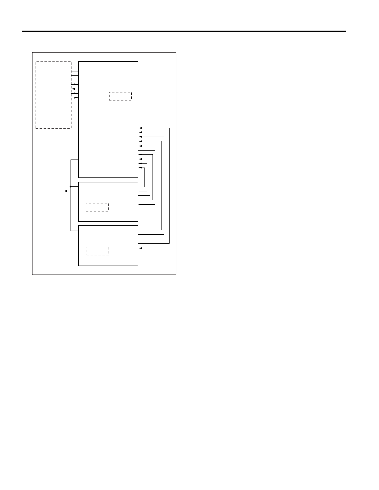
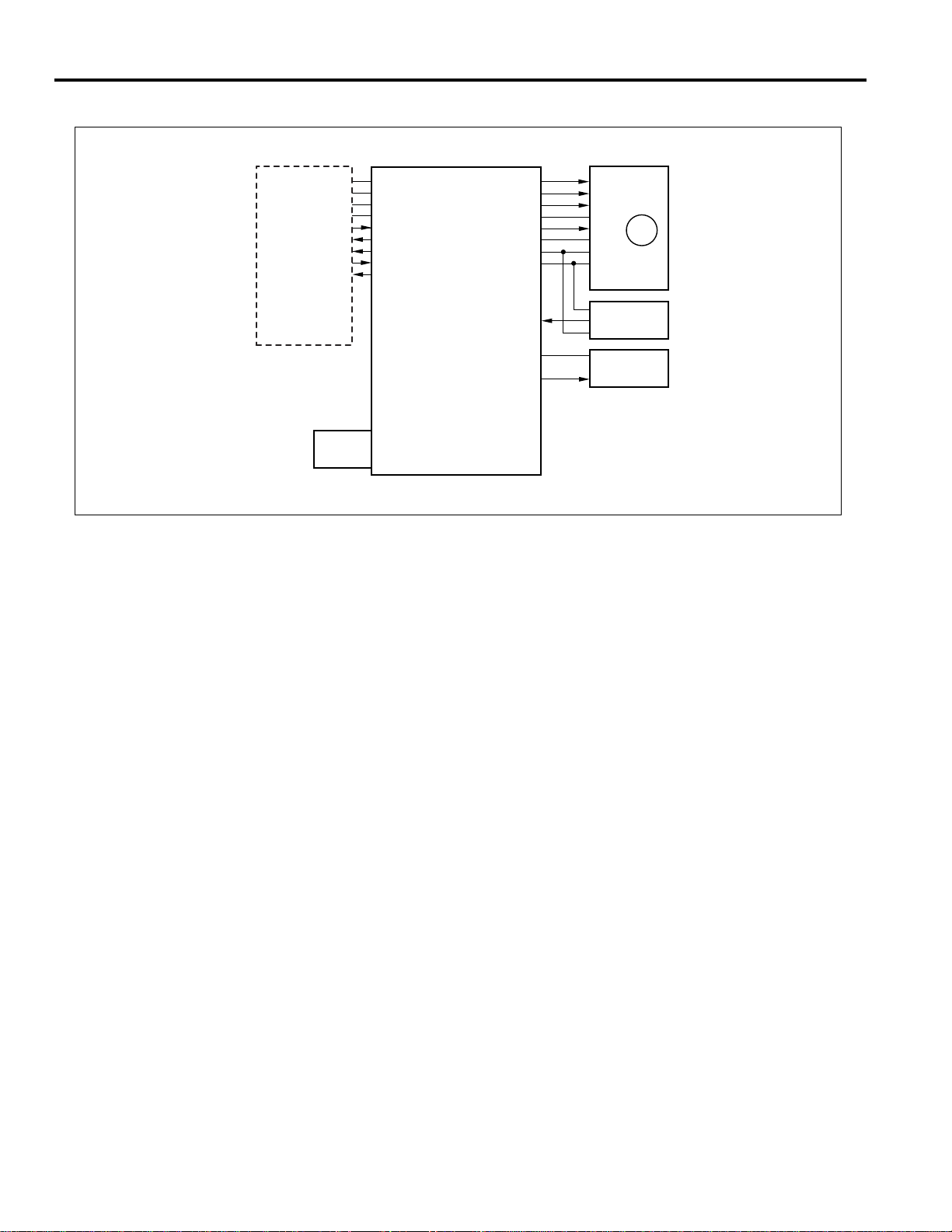
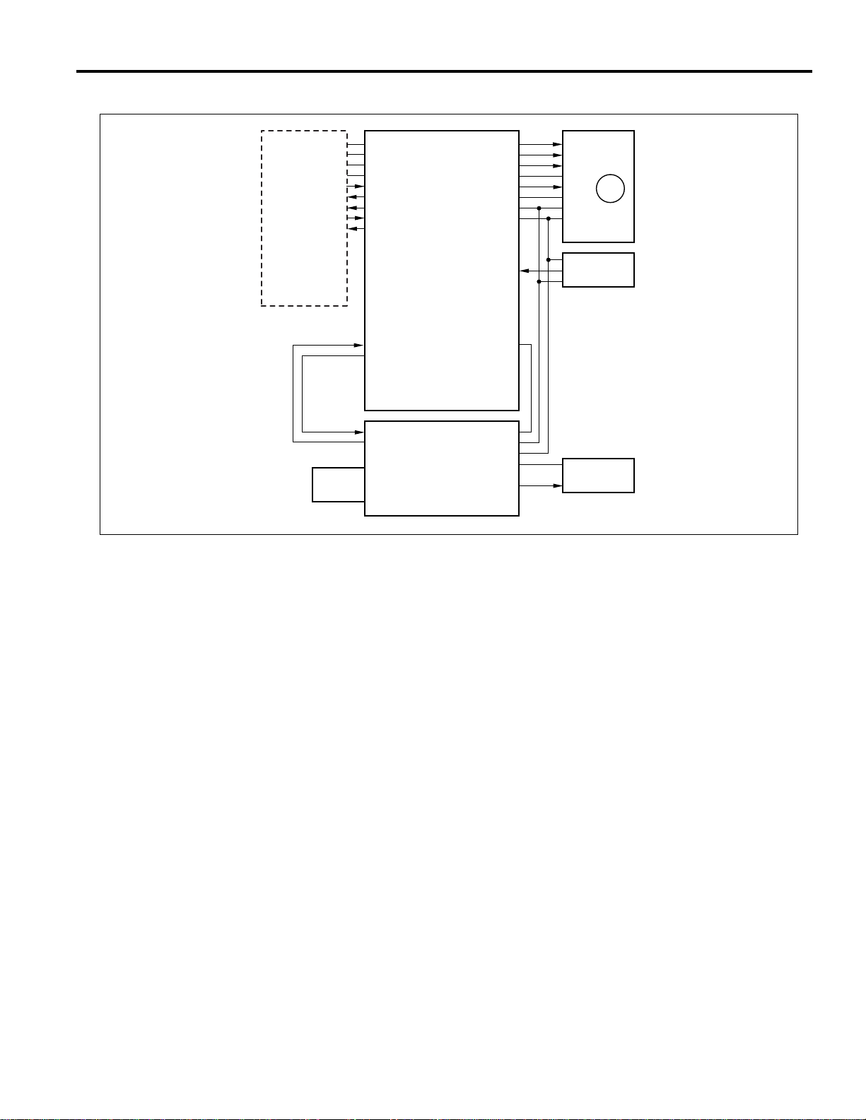
Paper Feed and No-Paper Detection Control
24VDC(DCPS1)
PGND(DCPS1)
5VDC(SCDB)
SGND(SCDB)
DB MTXD(SCDB)
(SCDB)
(SCDB)
DB SACK(SCDB)
(PRDB)
MAIN BODY
PS402
PS404
PS406
DB MACK
DB SRXD
MPS DATA
SD403 DRIVE
SD402 DRIVE
5VDC
SGND
PS402
PS404
5VDC
SGND
PS404
PS406
5VDC
SGND
PS406
M401 CONT
M401 CLK
M401 H/L
24VDC
M401 CW/CCW
PGND
SGND
5VDC
PS401
24VDC
SD401 DRIVE
24VDC
PFUDB(U)
24VDC
SD402 DRIVE
PFUDB(M)
24VDC
SD403 DRIVE
PFUDB(L)
M401
PS401
SD401
SD402
SD403
Paper is fed by the drive force of M401 (paper feed) to
each paper feed roller and each feed roller through
SD401 (paper feed (U)), SD402 (paper feed (M)) and
SD403 (paper feed (L)).
The M401 and SD401 are driven by the PFUDB (U) (PFU
drive board (U)) and controlled by the PFUDB (U) in the
main body.
The SD402 is driven by the PFUDB (M) (PFU drive board
(M)), the SD403 is driven by the PFUDB (L) (PFU drive
board (L)) and controlled by the PFUDB (U).
1. Operation
a. Operation when copying
Paper feed for the first sheet starts a specified time
after the start button is turned ON and paper feed
operation starts when the M401 (paper feed) and
SD401 (SD402 or SD403) turn ON.
The M401 turns OFF a specified time after the PS401
(paper feed detect) detects the leading edge of the
page. Each solenoid turns OFF a specified time after
being turned ON.
Paper feed for the second and subsequent sheets
starts a specified time after the SD401 (SD402 or
SD403) turns ON every time paper is fed.
When the paper tray is empty, PS402 (no paper
detect (U)), PS404 (no paper detect (M)) or PS406
(no paper detect (L)) changes to a high signal (H), to
inform the paper feed drive board that there is no
paper in the tray.
1-4
Page 13

DB-208/608
2. Signals
a. Input signals
(1) PS401 (PS401 to PFUDB (U))
This signal is output when PS401 (paper feed detect)
detects paper passing through the paper conveyance
section. It changes to an [H] level when paper is
detected.
(2) PS402 (PS402 to PFUDB (U))
This signal is a no-paper detecting signal for the
paper tray (U).
[L]: When there is no paper in the tray
[H]: When there is paper in the tray
(3) PS404 (PS404 to PFUDB (M) to PFUDB (U))
This signal is a no-paper detecting signal for the
paper tray (M).
[L]: When there is no paper in the tray
[H]: When there is paper in the tray
(4) PS406 (PS406 to PFUDB (L) to PFUDB (U))
This signal is a no-paper detecting signal for the
paper tray (L).
[L]: When there is no paper in the tray
[H]: When there is paper in the tray
(5) DB MTXD (MAIN BODY to PFUDB (U))
The serial data line informs DB of main body
operation
(6) DB SACK (MAIN BODY to PFUDB (U))
This signal is the transmission approved signal from
the main body to the DB.
b. Output signals
(1) M401 CONT (PFUDB (U) to M401)
This is the ON/OFF control signal for M401 (paper
feed).
[L]: M401 ON
[H]: M401 OFF
(2) M401 CLK (PFUDB (U) to M401)
This is the reference clock signal for M401 rotation
speed control.
(3) M401 H/L (PFUDB (U) to M401)
This is the signal for rotation speed control for M401.
[L]: High speed
[H]: Low speed
(4) M401 CW/CCW (PFUDB (U) to M401)
This is the signal for rotation direction control for
M401.
[L]: Forward direction
[H]: Reverse direction
(5) SD401 DRIVE (PFUDB (U) to SD401)
This is the ON/OFF control signal for SD401.
[L]: ON
[H]: OFF
(6) SD402 DRIVE (PFUDB (U) to PFUDB (M) to SD402)
This is the ON/OFF control signal for SD402 (paper
feed (M)).
[L]: ON
[H]: OFF
(7) SD403 DRIVE (PFUDB (U) to PFUDB (L) to SD403)
This is the ON/OFF control signal for SD403 (paper
feed (L)).
[L]: ON
[H]: OFF
(8) DB SRXD (PFUDB (U) to MAIN BODY)
The serial data line informs main body of DB
operation.
(9) DB MACK (PFUDB (U) to MAIN BODY)
This signal is the transmission approved signal from
the main body to the DB.
(10) MPS DATA (PFUDB (U) to MAIN BODY)
This signal feeds the PS401 detecting signal back to
the main body.
1-5
Page 14
DB-208/608
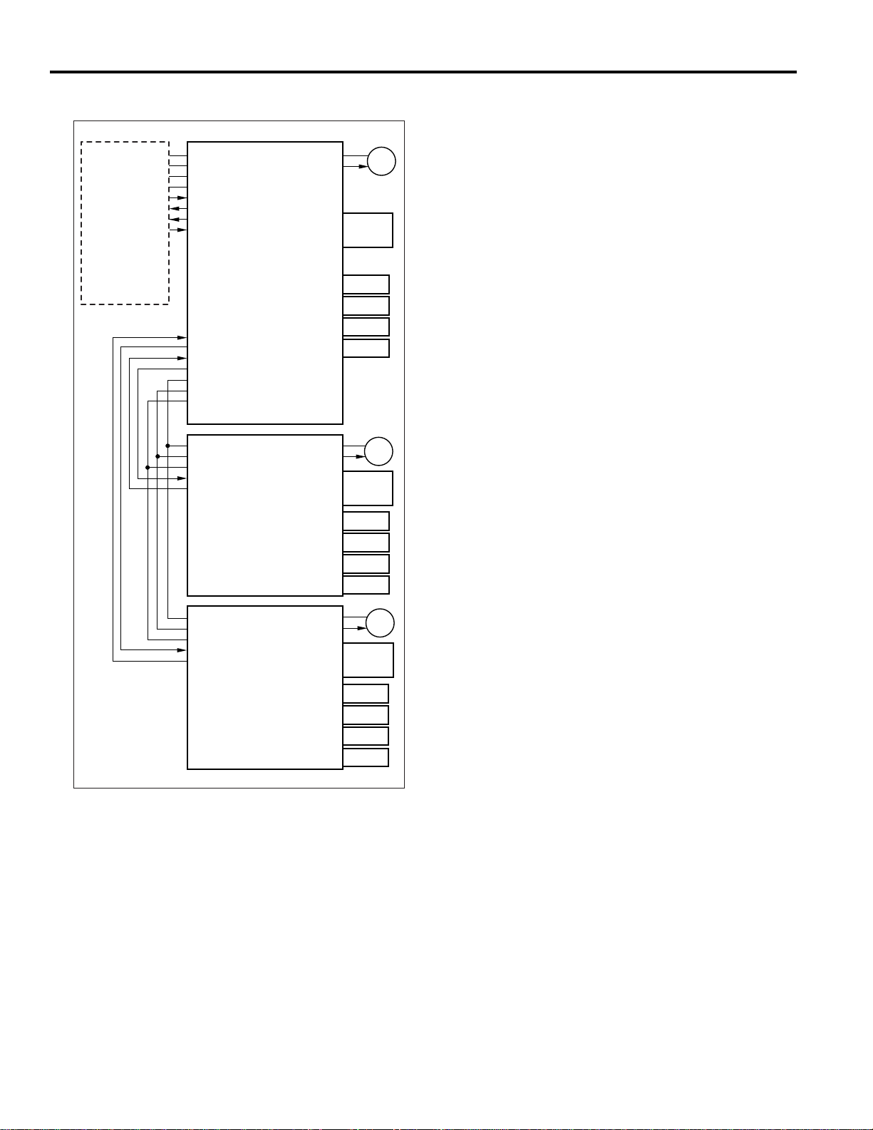
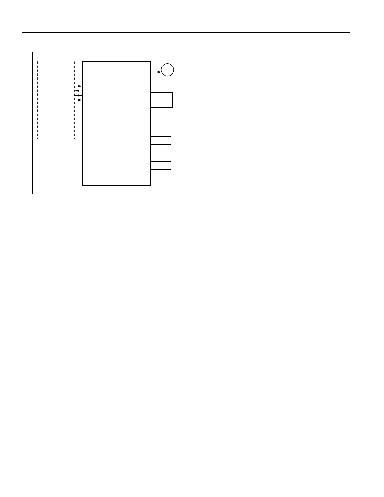
Tray Up Control
24VDC(DCPS1)
PGND(DCPS1)
5VDC(SCDB)
SGND(SCDB)
DB MTXD(SCDB)
(SCDB)
(SCDB)
DB SACK(SCDB)
MAIN BODY
DB MACK
DB SRXD
M404 DRIVE
M403 DRIVE
5VDC
SGND
24VDC
PS405
24VDC
M402 DRIVE
SGND
5VDC
PS403
PFUDB(U)
24VDC
M403 DRIVE
SGND
5VDC
PS405
PFUDB(M)
M402
PS403
SW401
SW402
SW403
SW404
M403
PS405
SW401
SW402
SW403
SW404
1. Operation
The tray is raised when each motor turns ON after
the SW401, 402, 403 or 404 (paper size-detection)
turns ON.
When PS403 (upper limit detect (U)), PS405 (upper
limit detect (M)), or PS407 (upper limit detect (L))
detects the upper limit of the paper in the tray and
turns ON, the lift-up motor turns OFF and the tray
stops.
When paper is fed, each upper limit-detecting sensor
turns OFF and the tray is raised when the lift-up
motor turns ON.
The paper tray is lowered mechanically.
PS407
24VDC
M404 DRIVE
SGND
5VDC
PS405
M404
PS407
SW401
SW402
SW403
PFUDB(L)
SW404
The paper tray is raised by transmitting the M402 (up/
down (U)), M403 (up/down (M)), or M404 (up/down (L))
driving force to the paper lifting lever.
The M402 is driven by PFUDB (U) (PFU drive board (U))
and controlled by the PFUDB (U) in the main body.
The M403 is driven by the PFUDB (M) (PFU drive board
(M)), the M404 is driven by the PFUDB (L) (PFU drive
board (L)) and controlled by the PFUDB (U) in the main
body.
1-6
Page 15

2. Signals
a. Input signals
(1) PS403 (PS403 to PFUDB (U))
Upper limit-detecting signal on upper tray.
There is an [H] signal when the upper limit of paper is
detected.
(2) PS405 (PS405 to PFUDB (M) to PFUDB (U))
Upper limit-detecting signal on middle tray.
There is an [H] signal when the upper limit of paper is
detected.
(3) PS407 (PS407 to PFUDB (L) to PFUDB (U))
Upper limit-detecting signal on lower tray.
There is an [H] signal when the upper limit of paper is
detected.
(4) SIZE A, B, C, D (SW401~404 to PFUDB (U))
Paper size-detecting sensor on upper tray.
(5) SIZE A, B, C, D (SW401~404 to PFUDB (M) to PFUDB (U))
Paper size-detecting sensor on middle tray.
(6) SIZE A, B, C, D (SW401~404 to PFUDB (L) to PFUDB (U))
Paper size-detecting sensor on lower tray.
DB-208/608
b. Output signals
(1) M402 DRIVE (PFUDB (U) to M402)
This is the ON/OFF control signal for M402 (up/down (U)).
[L]: ON
[H]: OFF
(2) M403 DRIVE (PFUDB (U) to PFUDB (M) to M403)
This is the ON/OFF control signal for M403 (up/down (M)).
[L]: ON
[H]: OFF
(3) M404 DRIVE (PFUDB (U) to PFUDB (L) to M404)
This is the ON/OFF control signal for M404 (up/down (L)).
[L]: ON
[H]: OFF
1-7
Page 16
DB-208/608
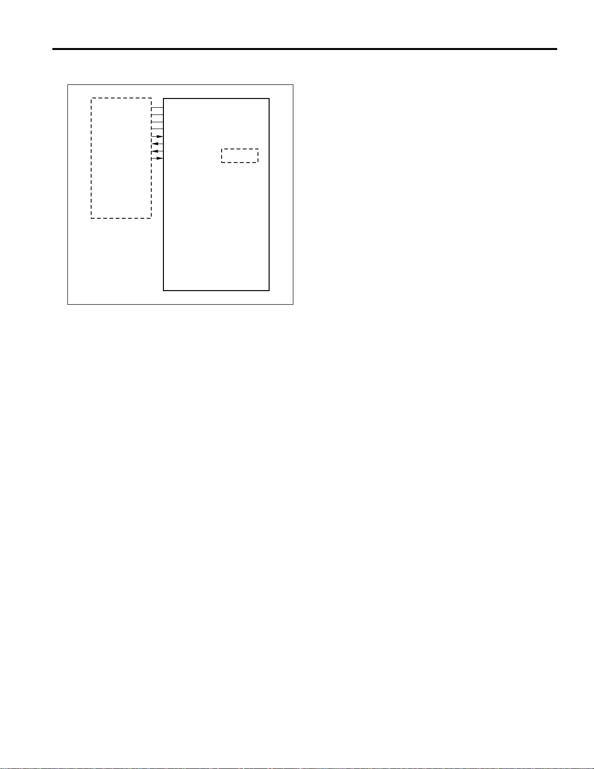
Paper Size Detection Control
24VDC(DCPS1)
PGND(DCPS1)
5VDC(SCDB)
SGND(SCDB)
DB MTXD(SCDB)
(SCDB)
(SCDB)
DB SACK(SCDB)
MAIN BODY
DB MACK
DB SRXD
5VDC
SGND
PAPER SIZE DETECT
SWITCH
PAPER SIZE DETECT
SWITCH
SIZE SCN2
SELECT
SIZE SCN1
PFUDB(U)
SIZE A
SIZE B
SIZE C
SIZE D
PFUDB(M)
2. Signals
a. Output signals
(1) SIZE SCN 1 (PFUDB (U) to PFUDB (M))
Paper size-detecting scan signal for middle tray.
(2) SIZE SCN 2 (PFUDB (U) to PFUDB (L))
Paper size-detecting scan signal for lower tray.
SIZE A
SIZE B
PAPER SIZE DETECT
SWITCH
SIZE C
SIZE D
PFUDB(L)
Each drive board, PFUDB (U) (PFU drive board (U)),
PFUDB (M) (PFU drive board (M)) and PFUDB (L) (PFU
drive board (L)) is fitted with a series of tact switches for
detecting paper size. This informs the main body of the
paper size in each tray, the upper tray directly through the
main body and the middle and lower trays through the
PFUDB.
1. Operation
Each tray has a series of actuators that are operated
by the paper guides. When each tray is inserted,
these projections turn the tact switches on each drive
board OFF and ON. The PFUDB (PFU) determines
the paper size of the PFU from the ON/OFF
combinations.
1-8
Page 17
DISASSEMBLY AND REASSEMBLY
DB-208/608
CAUTION: Ensure the power cord is unplugged
.
from the socket.
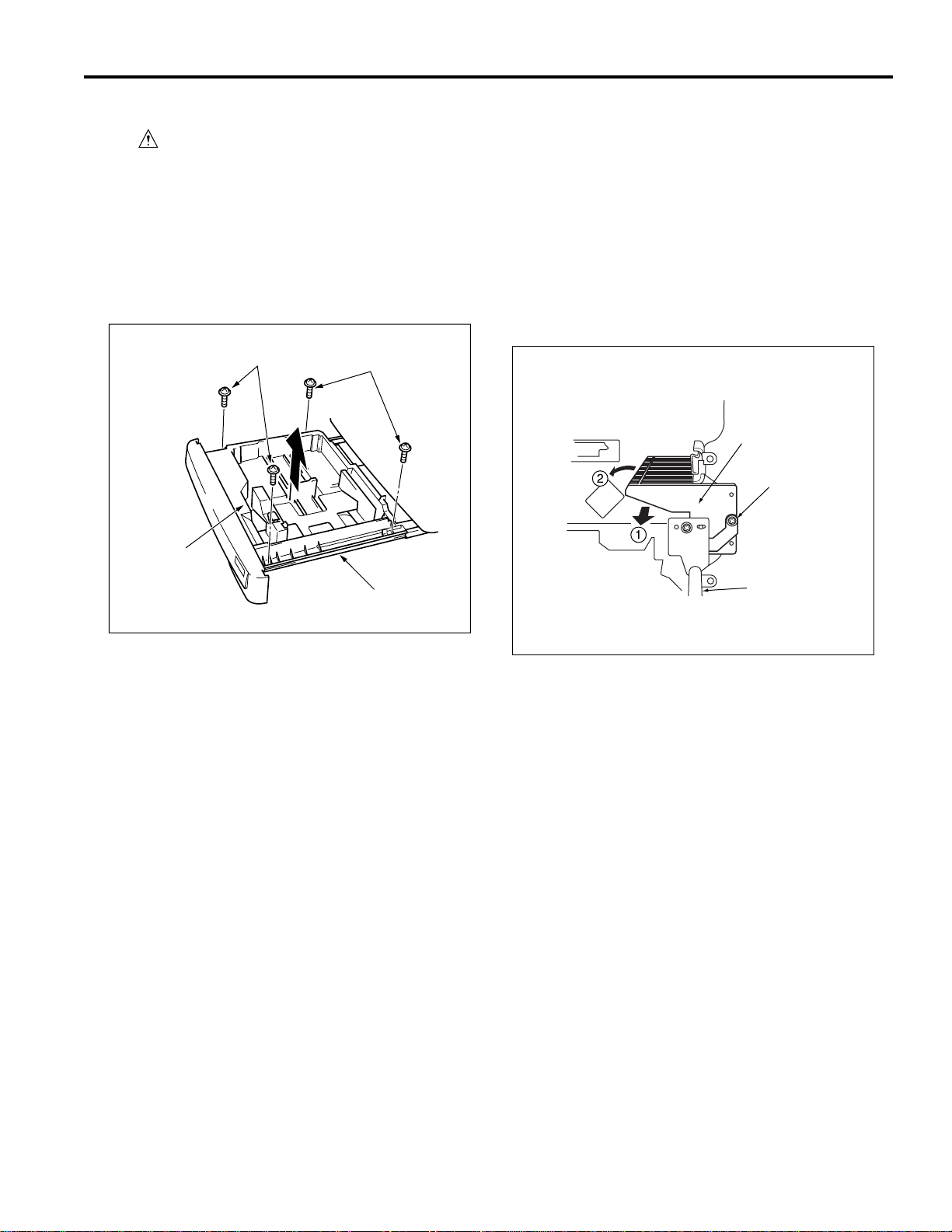
Removing and Reinstalling the Paper
Feed Tray
a. Procedure
(1) Pull out the paper feed tray and remove the two set
screws on the left and the two set screws on the right.
(2) Remove the paper feed tray from the guide rail.
Set screws
Paper
feed tray
Set screws
Guide rail
Removing and Reinstalling the Paper
Feed Unit
a. Procedure
(1) Slide out the paper tray towards you.
(2) To remove the middle or the low paper feed unit, remove
the set screw and pull out the paper feed unit (S) to the
direction 1 .
To remove the upper paper feed unit, remove the set
screw and pull out the paper feed unit to the direction
2.
Paper feed unit
Set scerw
Guide rail
(3) To reinstall, reverse the procedure above.
(3) Reinstall the paper feed unit by reversing the procedure
above.
Caution: After installing the paper feed unit, take a
copy to check that the copier is operating
correctly. There is a possibility the paper
will not feed if the rocking gear and paper
feed SD are not in their correct positions.
1-9
Page 18
DB-208/608
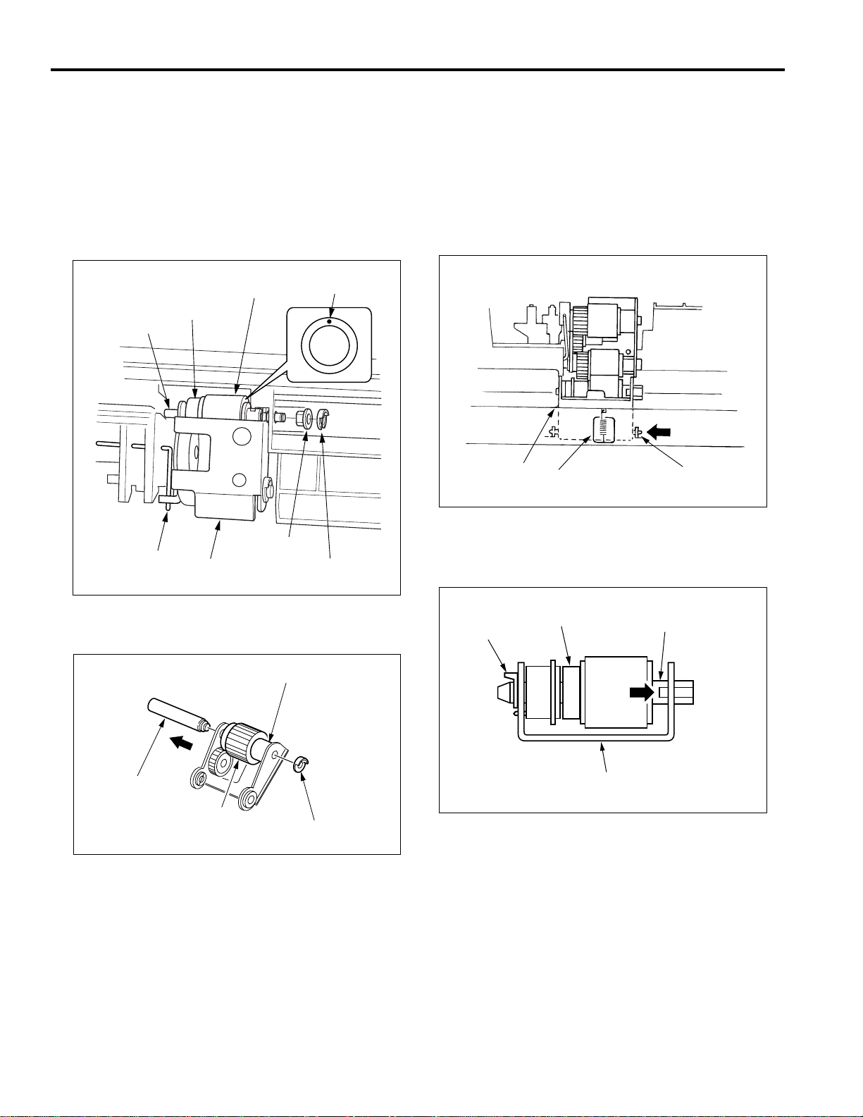
Replacing the Separation Rubber and
the Paper Supply Rubber
a. Procedure
(1) Remove the paper feed unit.
(2) Remove the stop ring and shaft holder.
(3) While pulling out the paper feed shaft, remove the feed
roller from the paper feed roller unit.
Removing and Reinstalling the DoubleFeed Prevention Roller
a. Procedure
(1) Remove the paper feed unit.
(2) Remove the double-feed pressure spring.
(3) While pressing the shaft in the direction of the arrow,
remove the double-feed prevention unit from the paper
feed unit.
Paper
feed shaft
Rocking
shaft
Separation
roller
Paper feed
roller unit
Separation
rubber
Shaft
bushing
Marking
Stop ring
(4) Remove the stop ring and, pulling the guide shaft in the
direction of the arrow, remove the paper feed roller
Paper feed roller
Double-feed
prevention unit
Double-feed
prevention spring
Shaft
(4) Remove the stop ring, then while pushing the projection
on the lever click shaft, pull out the lever click shaft and
remove the double feed prevention roller.
Double-feed
Stop ring
prevention roller
Lever click shaft
Guide shaft
Paper supply rubber
Stop ring
(5) Remove the separation rubber from the separation
roller.
(6) Remove the paper supply rubber from the paper feed
roller.
(7) To reinstall, reverse the above procedure.
Caution: Make sure each roller rubber is installed
in the correct direction. Reinstall so that
the rocking shaft fits inside the paper
feed roller unit.
Double-feed
prevention unit
(5) Reinstall the double-feed prevention roller by reversing
the procedure above.
Caution: After reinstallation, make sure that the
double-feed pressure spring moves the
double-feed prevention roller smoothly.
1-10
Page 19

DB-608 PRODUCT SPECIFICATIONS
Type
Type: Paper feed tray (front loading)
Functions
Paper size: (Upper tray) 8.5 x 11/8.5 x 11R/
8.5 x 14/11x17
(Lower tray) 8.5 x 11/8.5 x 11R
Paper type: 16lb. to 24lb. high-quality paper
Maximum
paper storage: Upper tray: 500 sheets (22 lb.)
Lower tray: 1500 sheets (22 lb.)
Particulars of Machine
Power source: 24/5 V DC (supplied from main
body)
Power
consumption: Maximum 40 VA
Weight: Approximately 57 lb. (including
stand)
DB-208/608
Machine
dimensions: Width 24.0 in.
Depth 23.1 in.
Height 16.9 in.
Maintenance and Life
Maintenance: Same as the main body
Operating Environment
Temperature: 50°F to 86°F
Humidity: 10% to 80% RH
Note: These specifications are subject to change
without notice.
2-1
Page 20
DB-208/608
CENTER CROSS-SECTIONAL VIEW
Separation roller
Tray
DRIVE SYSTEM DIAGRAM
Paper feed roller
Paper feed roller
Conveyance rollers (upper)
Double-feed
prevention roller
Conveyance
rollers (lower)
Separation
roller
Double-feed
prevention roller
Paper feed motor (M401)
Up/down motor (PFU) (M402)
Up/down motor (LCT) (M403)
Intermediate
conveyance rollers
Separation roller
Double-feed prevention roller
Paper feed roller
2-2
Page 21
500-SHEET PAPER TRAY UNIT
Composition
Separation roller
Double-feed
prevention roller
Paper feed roller
Guide release lever
Paper feed trays
DB-208/608
Intermediate
conveyance rollers
Paper feed door
Rear edge stopper
Paper feed tray
Mechanisms
Mechanisms
Paper feed
Paper lifting
Double-feed prevention
1st paper feed
Intermediate conveyance
Paper jam handling
No-paper detection
Paper size detection
Paper conveyance
Conveyance drive
Front cover
Side guide
Method
Paper feed roller
Paper lift-up plate
Torque limiter
Separation roller, paper
feed SD
Intermediate conveyance
roller
Double-feed prevention
roller pressure release
Photosensor
Tact switch
Roller conveyance
Timing belt
2-3
Page 22
DB-208/608
500-Sheet Paper Feed Tray and No-Paper Detection Control
24VDC(DCPS1)
PGND(DCPS1)
5VDC(SCDB)
SGND(SCDB)
DB MTXD(SCDB)
(SCDB)
(SCDB)
DB SACK(SCDB)
(PRDB)
DB MACK
DB SRXD
MPS DATA
MAIN BODY
5VDC
PS402
SGND
PS402
Paper is fed by the drive force of M401 (paper feed) to
each paper feed roller and each feed roller through
SD401 (paper feed (PFU)).
The M401 and SD401 are driven by the PFUDB (PFU)
(PFU drive board (PFU)) and controlled by the PFUDB
(PFU) in the main body.
M401 CONT
M401 CLK
M401 H/L
24VDC
M401 CW/CCW
PGND
SGND
5VDC
PS401
24VDC
SD401 DRIVE
PFUDB(PFU)
1. Operation
a. Operation when copying
Paper feed for the first sheet starts a specified time
after the start button is turned ON. The paper feed
operation starts when the M401 and SD401 turn ON.
The M401 turns OFF a specified time after the PS401
(paper feed detect) detects the leading edge of the
page. SD401 turns OFF a specified time after turning
ON.
Paper feed for the second and subsequent sheets
starts a specified time after the SD401 for the
previouspage turns ON.
When the paper tray is empty, PS402 (no paper
detect (PFU)) changes to a high signal (L), to inform
the PFUDB (PFU) in the main body that there is no
paper in the tray.
M401
PS401
SD401
2-4
Page 23

DB-208/608
2. Signals
a. Input signals
(1) PS401 (PS401 to PFUDB (PFU))
This signal is output when PS401 (paper feed detect)
detects paper passing through the paper
conveyance section. It changes to an [H] signal when
paper is detected.
(2) PS402 (PS402 to PFUDB (PFU))
This signal is a no-paper detecting signal for the
PFU.
[L]: When there is no paper in the tray
[H]: When there is paper in the tray
(3) DB MTXD (MAIN BODY to PFUDB (PFU))
The serial data line informs main body of DB
operation.
(4) DB SACK (MAIN BODY to PFUDB (PFU))
This signal is the transmission approved signal from
the main body to the DB.
b. Output signals
(1) M401 CONT (PFUDB (PFU) to M401)
This is the ON/OFF control signal for M401 (paper
feed).
[L]: M401 ON
[H]: M401 OFF
(2) M401 CLK (PFUDB (PFU) to M401)
This is the reference clock signal for M401 rotation
speed control.
(3) M401 H/L (PFUDB (PFU) to M401)
This is the signal for rotation speed control for M401.
[L]: High speed
[H]: Low speed
(4) M401 CW/CCW (PFUDB (PFU) to M401)
This is the signal for rotation direction control for
M401.
[L]: Forward direction
[H]: Reverse direction
(5) SD401 DRIVE (PFUDB (PFU) to SD401)
This is the ON/OFF control signal for SD401 (paper
feed (PFU)).
[L]: ON
[H]: OFF
(6) DB SRXD (PFUDB (PFU) to MAIN BODY)
The serial data line informs DB of main body
operation.
(7) DB MACK (PFUDB (PFU) to MAIN BODY)
This signal is the transmission approved signal from
the main body to the DB.
(8) MPS DATA (PFUDB (PFU) to MAIN BODY)
This signal feeds the PS401 detecting signal back to
the main body.
2-5
Page 24
DB-208/608
Tray-Up Control (PFU)
24VDC (DCPS1)
PGND (DCPS1)
5VDC (DCPS1)
(SCDB)
DB MTXD(SCDB)
(SCDB)
(SCDB)
DB SACK(SCDB)
DB MACK
DB SRXD
MAIN BODY
PFUDB(UPPER)
The paper tray is raised by transmitting the M402 (up/
down) driving force to the paper lifting lever.
The M402 is driven by the PFUDB (PFU) (PFU drive board
(PFU)) and controlled by the PFUDB (U) in the main body.
24VDC
M402 DRIVE
5VDC
SGND
PS403
M402
PS403
SW401
SW402
SW403
SW404
2. Signals
a. Input signals
(1) PS403 (PS403 to PFUDB (PFU))
Upper limit-detecting signal on PFU.
The signal is at [H] level when the upper limit of paper
is detected.
b. Output signals
(1) M402 DRIVE (PFUDB (PFU) to M402)
This is the ON/OFF control signal for M402.
[L]: ON
[H]: OFF
1. Operation
The tray is raised when the M402 turns ON after the
SW401, 402, 403 or 404 (paper size-detect) turn ON.
After the tray is raised, the PS403 (upper limit
detect (PFU)) detects the upper limit of the paper in
the tray. The M402 turns OFF and the tray stops.
When paper is fed the PS403 turns ON and the tray is
raised when the M402 turns ON again.
The paper tray is lowered mechanically.
2-6
Page 25
Paper Size Detection Control
24VDC(DCPS1)
PGND(DCPS1)
5VDC(SCDB)
SGND(SCDB)
DB MTXD(SCDB)
(SCDB)
(SCDB)
DB SACK(SCDB)
DB MACK
DB SRXD
MAIN BODY
The PFUDB (PFU) (PFU drive board (PFU)) is fitted with a
series of tact switches for detecting paper size. This
informs the main body of the paper size in each tray.
PAPER SIZE DETECT
SWITCH
PFUDB(UPPER)
DB-208/608
1. Operation
Each tray has a series of actuators that are operated
by the paper guides. When each tray is inserted,
these projections turn the tact switches on the
PFUDB (PFU) OFF and ON. The PFUDB (PFU)
determines the paper size of the PFU from the ON/
OFF combinations.
2-7
Page 26

DB-208/608
1500-SHEET PAPER TRAY UNIT
Composition
Rear edge stopper
Mechanism
Mechanisms
Paper stack
Paper lifting *1
Tray loading
*1: Paper lifting
Tray
Front cover
Method
Tray 1
Wire driven
Front loading
Side guide
Wire B
Drive AUX spring
Wire A
AUX wire
Wire D
Wire C
Drive pulley
Up/down motor
Coupling gear
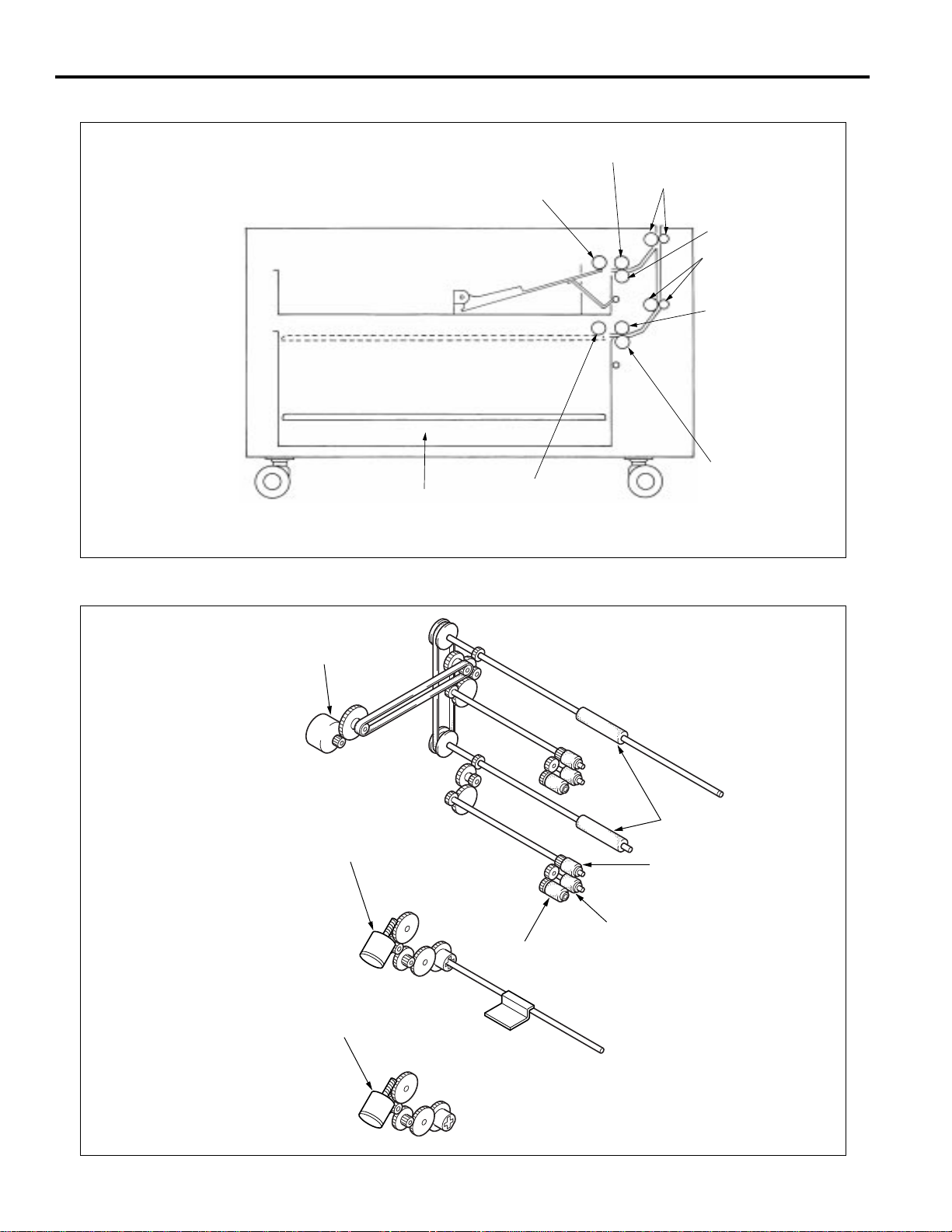
The paper tray (LCT) is suspended using four Up/
Down drive wires (A, B, C and D).
When paper is loaded into the tray, the tray moves
down due to the weight of the paper. The weight of
the paper is balanced by the tension of the drive
auxiliary spring.
When the paper tray (LCT) is inserted, the up/down
motor (M403) rotates, winding the wires on the drive
reel and raising the tray.
When the paper tray is withdrawn from the frame, the
tray drive section and the coupling separate from
each other. This causes the tray to move down to the
position where the paper is balanced by the tension
of the drive auxiliary spring.
2-8
Page 27
1500-Sheet Paper Feed Tray and No-Paper Detection Control
DB-208/608
24VDC(DCPS1)
PGND(DCPS1)
5VDC(SCDB)
SGND(SCDB)
DB MTXD(SCDB)
(SCDB)
(SCDB)
DB SACK(SCDB)
(PRDB)
MAIN BODY
PS404
DB MACK
DB SRXD
MPS DATA
SD402 DRIVE
PS404
5VDC
SGND
PS404
M401 CONT
M401 CLK
M401 H/L
M401 CW/CCW
PFUDB(PFU)
SD402 DRIVE
PFUDB(LCT)
24VDC
PGND
SGND
5VDC
PS401
24VDC
24VDC
M401
PS401
SD402
Paper is fed by transmitting the M401 (paper feed) driving
force to the paper feed roller and feed roller through
SD402 (paper feed (LCT)).
M401 is driven by the PFUDB (PFU drive board (PFU))
and controlled by the paper feed drive board PFUDB
(PFU) in the main body.
SD402 is driven by the PFUDB (PFU drive board (LCT))
and controlled by the PFUDB (PFU).
1. Operation
a. Initial operation when the power is switched ON
(1) When the power is switched ON, M401 goes ON for the
specified period.
Reason: This is to prevent the paper from being fed from
all of the paper trays at the same time when the
Start button is pressed, as a result of the the
ratchet claw of SD402 being disengaged due to
an impact when the machine was being
transported.
b. Operation when copying
Paper feed for the first sheet starts a specified time
after the start button is turned ON. The paper feed
operation starts when the M401 and SD402 turn ON.
The M401 turns OFF a specified time after the PS401
(paper feed detect) detects the leading edge of the
page. SD402 turns OFF a specified time after turning
ON.
Paper feed for the second and subsequent sheets
starts specified time after the SD402 for the previous
page turns ON.
When the paper tray is empty, PS404 (no paper
detect (LCT)) changes to a high signal (L), to inform
the PFUDB (PFU) in the main body that there is no
paper in the tray.
2-9
Page 28

DB-208/608
2. Signals
a. Input signals
(1) PS401 (PS401 to PFUDB (PFU))
This signal is output when PS401 (no paper detect)
detects paper passing through the paper
conveyance section. It changes to an [H] signal when
paper is detected.
(2) PS404 (PS404 to PFUDB (LCT) to PFUDB (PFU))
This signal is a no-paper detecting signal for the LCT.
[L]: When there is no paper in the tray
[H]: When there is paper in the tray
b. Output signals
(1) M401 CONT (PFUDB (PFU) to M401)
This is the ON/OFF control signal for M401 (paper
feed).
[L]: M401 ON
[H]: M401 OFF
(2) M401 CLK (PFUDB (PFU) to M401)
This is the reference clock signal for rotation speed
control for M401.
(3) M401 H/L (PFUDB (PFU) to M401)
This is the signal for rotation speed control for M401.
[L]: High speed
[H]: Low speed
(4) M401 CW/CCW (PFUDB (PFU) to M401)
This is the signal for rotation direction control for
M401.
[L]: Forward direction
[H]: Reverse direction
(5) SD402 DRIVE (PFUDB (PFU) to PFUDB (LCT) to SD402)
This is the ON/OFF control signal for SD402 (paper
feed (LCT)).
[L]: ON
[H]: OFF
(6) MPS DATA (PFUDB (PFU) to MAIN BODY)
This signal feeds the PS401 detecting signal back to
the main body.
2-10
Page 29

DB-208/608
Tray-Up Control (LCT)
24VDC(DCPS1)
PGND(DCPS1)
5VDC(SCDB)
SGND(SCDB)
DB MTXD(SCDB)
(SCDB)
(SCDB)
DB SACK(SCDB)
MAIN BODY
DB MACK
DB SRXD
M403 DRIVE
5VDC
SGND
24VDC
PS405
PFUDB(PFU)
5VDC
SGND
PS405
2. Signals
a. Input signals
(1) PS405 (PS405 to PFUDB (LCT) to PFUDB (PFU))
Upper limit-detecting signal for paper in the LCT.
The signal is [H] when the upper limit of the paper is
detected.
b. Output signals
(1) M403 DRIVE (PFUDB (PFU) to PFUDB (LCT) to M403)
This is the ON/OFF control signal for M403.
[L]: ON
[H]: OFF
M403
PS405
PFUDB(LCT)
SW405
The paper tray is raised when the M403 (up/down (LCT))
driving force is transmitted to the paper tray through the
up/down drive wires (four for each tray).
The M403 is driven by the PFUDB (LCT) (PFU detection
board (LCT)) and controlled by the PFUDB (PFU) (PFU
drive board (PFU)).
1. Operation
When the SW405 (LCT tray insertion detection) turns
ON, the M403 turns ON and raises the tray.
After the tray is raised, the PS405 (upper limit detect
(LCT)) detects the upper limit of the paper in the tray.
The M403 turns OFF and the tray stops.
When paper is fed the PS405 turns OFF and the tray
is raised when the M402 (up/down) turns ON again.
The paper tray is lowered mechanically.
2-11
Page 30

DB-208/608
DISASSEMBLY AND REASSEMBLY
CAUTION: Ensure the power cord is unplugged
from the socket.
Removing and Reinstalling the Paper
Feed Tray
a. Procedure
(1) Pull out the paper feed tray and remove the two screws
on the left and the two screws on the right.
(2) Remove the paper feed tray from the guide rail.
Set screws
Paper
feed tray
Set screws
Removing and Reinstalling the Paper
Feed Unit
a. Procedure
(1) Pull out the paper tray towards you.
(2) Remove the two set screws, then remove the tray
stopper.
Tray stopper
Set screws
Guide rail
(3) To reinstall the paper feed tray, reverse the procedure
above.
(3) Remove the set screw, then pull forward and remove
the paper feed unit, using the guide rail as a guide.
To remove the upper paper feed unit, remove the set
screw, then pull out the unit in the direction of arrow .
Paper feed unit
Set scerw
Guide rail
(4) Reinstall the paper feed unit by reversing the procedure
above.
Caution: After installing the paper feed unit, take a
copy to check that the copier is operating
correctly. There is a possibility the paper
will not feed if the rocking gear and paper
feed SD are not in their correct positions.
2-12
Page 31

DB-208/608
Replacing the Separation Rubber and
the Paper Supply Rubber
a. Procedure
(1) Remove the paper feed unit.
(2) Remove the stop ring and shaft holder.
(3) While pulling out the paper feed shaft, remove the
separation roller from the paper feed roller unit.
Paper
feed shaft
Separation
roller
Separation
rubber
Marking
(7) To reinstall, reverse the above procedure.
Note 1: Make sure each roller rubber is installed in
the correct direction.
Note 2: Reinstall the rubber so that the rocking
shaft fits inside the paper feed roller unit.
Shaft
Rocking
shaft
Paper feed
roller unit
bushing
Stop ring
(4) Remove the stop ring and, pulling the guide shaft in the
direction of the arrow, remove the paper feed roller.
Paper feed roller
Guide shaft
Paper supply rubber
Stop ring
(5) Remove the separation rubber from the separation
roller.
(6) Remove the paper supply rubber from the paper feed
roller.
2-13
Page 32

DB-208/608
Removing and Reinstalling the DoubleFeed Prevention Roller
a. Procedure
(1) Remove the paper feed unit.
(2) Remove the double-feed pressure spring.
(3) While pressing the shaft in the direction of the arrow,
remove the double-feed prevention unit from the paper
feed unit.
Double-feed
prevention unit
Double-feed
prevention spring
Shaft
(4) Remove the stop ring, then while pushing the projec-
tion on the lever click shaft, pull out the lever click shaft
and remove the double feed prevention roller.
Double-feed
prevention roller
Stop ring
Double-feed
prevention unit
Lever click shaft
(5) Reinstall the double-feed prevention roller by reversing
the procedure above.
Caution: After reinstallation, make sure that the
double-feed pressure spring moves the
double-feed prevention roller smoothly.
2-14
Page 33

DB-208/608
Removing and Reinstalling the Paper
Feed Tray (LCT)
a. Procedure
(1) Slide out the paper tray and remove the two right and
two left screws.
(2) Remove the paper tray from the rails.
Set screws
Set screws
Paper tray (LCT)
(3) Reinstall the paper tray by reversing the procedure
above.
Removing and Reinstalling the Front
Tray Cover (LCT)
a. Procedure
(1) Remove the paper tray.
(2) Remove the five screws, then remove the front tray
cover.
Set screws
Front
Set screws
(3) Reinstall the front tray cover by reversing the procedure
above.
tray cover
2-15
Page 34

DB-208/608
Replacing the Up/Down Wires
Caution 1: After replacing the up/down drive wires
or readjusting wire tension, move the
tray up and down to make sure that it
moves smoothly.
Caution 2: Be careful not to cross or overlap the
wires.
Removing the Up/Down Wires
2. Remove screw A.
3. Loosen screw B and rotate the tension fitting in a
clockwise direction.
4. Remove the AUX wire from the drive AUX spring.
Tension fitting
Set screw A
Drive AUX spring
Set screw B
AUX wire
Caution 3: After installing the up/down wires,
adjust the inclination of the tray.
Wire A: 513.9±0.4 mm
Wire B: 288.9±0.4 mm
Wire C: 305±0.4 mm
Wire D: 410.5±0.4 mm
AUX wire: 245.2±0.5 mm
Wire D
Wire A
Wire C
Drive
AUX spring
AUX wire
Wire B
Set screw
1. Remove the wire protection covers.
Wire A
AUX wire
Drive pulley (front)
E-ring
5. Remove the E-ring, then remove the drive
pulley (front).
Wire B
Wire protection
cover
Front side
Drive pulley (rear)
6. Slide the drive shaft to the rear, remove the E-ring,
then slide the drive pulley (rear) to the front.
Set screw
E-ring
Wire C
Wire D
2-16
Page 35

<Installing the Up/Down Wires>
DB-208/608
7. Connect the AUX wire to the drive AUX
spring.
8. Rotate the tension fitting in an anti clockwise direction and replace screw A.
9. Tighten screw B.
Tension fitting
Screw A
AUX wire
Drive AUX
spring
AUX wire
Screw B
Wire A
2. Thread wires A and B through the
grooves in the pulley, then thread
them above the wire adjusting
material.
Wire A
1. Route the wire .
Wire B
5. Insert the AUX wire, wire A and
wire B into their respective holes
in the drive shaft, slide the drive
pulley onto the drive shaft, then
secure with the E-ring.
Wire B
3. Thread wires C and D through the
grooves in the pulley.
Wire C
Wire D
4. Insert wires C and D into their respective
holes in the drive shaft, slide the drive
pulley onto the drive shaft, then secure
with the E-ring.
Wire C
Wire D
Drive pulley
Wire
protection
cover
Set screw
10. Replace the wire protection
cover.
Drive pulley
Wire A
AUX wire
6. Wind the AUX wire five turns
clockwise onto the drive pulley.
Wire B
2-17
Wire
protection
cover
Set screw
11. Replace the wire protection
cover.
Page 36

DB-208/608
This page left blank intentionally.
2-18
Page 37

DB-208 ELECTRICAL PARTS LAYOUT DRAWING
PFUDB (upper)
PFU drive board (U)
PS402
PS403
Upper limit detect PS (U)
SD401
Paper feed SD (PFU) (U)
PS401
Paper feed detect PS
PS404
No paper detect PS (M)
(DB-208 only)
SD402
Paper feed SD (M)
(DB-208 only)
PS405
Upper limit detect PS (M)
(DB-208 only)
PS406
No paper detect PS (L)
(DB-208 only)
SD403
Paper feed SD (L)
(DB-208 only)
No paper detect PS (U)
M401
Paper feed motor
PFUDB (L)
PFU drive board (L) (DB-208 only)
PS407
Upper limit detect PS (L) (DB-208 only)
M402
Up/down motor (U)
M403
Up/down motor (M) (DB-208 only)
PFUDB (M)
PFU drive board (M)
(DB-208 only)
M404
Up/down motor (L)
(DB-208 only)
PTC
PTC heater
DIAGRAMS
DB-608 ELECTRICAL PARTS LAYOUT DRAWING
PS402
No paper detect PS (PFU)
PS403
Upper limit detect PS (PFU)
PS401
Paper feed detect PS
SD401
Paper feed SD (PFU)
PS404
No paper detect PS (LCT)
SD402
Paper feed SD (LCT)
PS405
Upper limit detect PS (LCT)
PFUDB (PFU)
PFU drive board (PFU)
M401
Paper feed motor
PFUDB (LCT)
PFU drive board (LCT)
M402
Up/down motor (PFU)
M403
Up/down motor (LCT)
PTC
PTC heater
3-1
Page 38

DIAGRAMS
DB-208 CONNECTOR LAYOUT DRAWING
310 (GY:18 PIN)
321 (W:12 PIN)
300 (GY:16 PIN)
305 (BK:9 PIN)
312 (W:3 PIN)
313 (W:3 PIN)
317A (W:3 PIN)
317B (W:3 PIN)
311 (GY:24 PIN)
316B (W:13 PIN)
316B (W:3 PIN)
306 (BK:8 PIN)
DB-608 CONNECTOR LAYOUT DRAWING
312 (W:3 PIN)
316A (W:13 PIN)
318A (W:3 PIN)
320 (W:2 PIN)
312 (W:3 PIN)
313 (W:3 PIN)
317 (W:3 PIN)
310 (GY:18 PIN)
311 (GY:24 PIN)
306 (BK:8 PIN)
321 (W:12 PIN)
312 (W:3 PIN)
316A (W:13 PIN)
318 (W:3 PIN)
320 (W:2 PIN)
300 (GY:16 PIN)
305 (BK:9 PIN)
3-2
Page 39

DB-208 OVERALL WIRING DIAGRAM
(SCDB)
(SCDB)
DB SRXD
(SCDB)
P
300-7
300-8
310-A7
P 310-A4
DB SRXD
PS401
311-B2 H
312-2
312-3
PS401
(PRDB)
(DCPS1)
X RESET
28VDC
(PRDB)
300-10
300-9
300-13
320-2
310-A8
P 310-A9
MPS DATA
312-1
(DCPS1)
P.GND
300-12
PTC
320-1
24VDC
311-A2
MAIN BODY
PTC HEATER
S.GND
5VDC
311-B1
311-A1
PS406
PS407
311-B11
311-B12
(U)
MOTOR
UP/DOWN
M 402
R
BK
312-1
312-3
H
24VDC
M402 DRIVE
M404 DRIVE
SD403 DRIVE
SIZE SCN2
H
P
H
311-B10
311-B9
311-A4
PAPER
R
313-1
24VDC
SIZE D
SIZE C
311-B8
311-B7
(U)
FEED
SOLENOID
SD401
DETECT
NO PAPER
BK
313-3
H
5VDC
SD401 DRIVE
SIZE B
SIZE A
PS404
311-B6
311-B5
311-A11
(U)
SENSOR
PS402
PS402
S.GND
PS405
M403 DRIVE
H
311-A12
311-A10
UPPER LIMIT
SD402 DRIVE
H
311-A9
(DCPS1)
P.GND
300-15
310-B4
M401 CONT
M401 CLK
310-B6
310-B8
321-3
321-4
321-5
(DCPS1)
(DCPS1)
P.GND
24VDC
300-2
300-14
310-B3
310-A3
M401 H/L
24VDC
310-B7
310-B2
321-10
321-12
M 401
(DCPS1)
(SCDB)
(SCDB)
24VDC
5VDC
S.GND
DB MTXD
300-1
300-3
300-4
300-5 P
310-A2
310-A1
310-B1
310-A6
M401 CW/CCW
P.GND
310-B9
310-B5
321-8
321-2
321-1
(SCDB)
300-6
P 310-A5
DB MACK
DETECT
SENSOR
PS403
5VDC
S.GND
SELECT
SIZE SCN1
P
311-B3
311-A3
(U)
PS403
SIZE D
SIZE C
311-A8
311-A7
SW401
SIZE B
SIZE A
311-A6
311-A5
SW402
SW403
O
O
SW404
PFUDB (U)
O
O
(M)
MOTOR
UP/DOWN
M 403
R
BK
318A-1
318A-3
H
24VDC
M403 DRIVE
5VDC
316A-13
FEED
PAPER
SD402
R
BK
317A-1
317A-3
H
24VDC
SD402 DRIVE
S.GND
24VDC
316A-7
316A-10
(M)
SOLENOID
DETECT
NO PAPER
PS404
5VDC
S.GND
SIZE A
SIZE B
SIZE C
316A-1
316A-2
316A-3
O
O
O
O
(M)
SENSOR
PS404
SIZE D
SIZE SCN1
SELECT
P
316A-4
316A-5
316A-6
O
O
O
O
O
O
(M)
DETECT
SENSOR
UPPER LIMIT
PS405
5VDC
PS405
S.GND
SD402 DRIVE
M403 DRIVE
PS405
PS404
H
H
316A-8
361A-9
316A-11
361A-12
O
O
O
O
O
SW401
SW402
SW403
SW404
PFUDB (M)
(L)
MOTOR
UP/DOWN
M 404
R
BK
318B-1
318B-3
H
24VDC
M404 DRIVE
FEED
PAPER
SD403
R
317B-1
24VDC
5VDC
S.GND
316B-13
316B-7
(L)
SOLENOID
DETECT
NO PAPER
BK
PS406
317B-3
H
5VDC
S.GND
SD403 DRIVE
24VDC
SIZE A
SIZE B
SIZE C
316B-10
316B-1
316B-2
316B-3
(L)
SENSOR
PS406
SIZE D
SIZE SCN2
P
316B-4
316B-5
(L)
DETECT
SENSOR
UPPER LIMIT
PS407
5VDC
PS407
S.GND
SD403 DRIVE
M404 DRIVE
PS407
H
316B-6
316B-8
361B-9
316B-11
SW401
SW402
PS406
H
361B-12
SW403
SW404
[How to see the diagram]
1.The signals shown reflect levels present
under normal idling conditions with
the main switch turned ON.
2.Wiring symbols in the figure are as follows.
(1) [Symbol]
(2)
Crimp
Signal typs are as follows :
Active high
H
Active low
L
Analog signal
*
Pulse signal
P
V
50-1
V
Connector
Wire(Violet)
(3) RC is ribbon cable.
(4) Signal flow
The solid black circle ( ) among
the connector symbols ( )
PFUDB (L)
indicates the direction of signal flow.
Example)
5VDC
PS1
Direction of
signal flow
CB
SGND
(5) [Colour code]
BN - Brown B - Blue
R - Red V - Violet
O - Orange GY - Gray
Y - Yellow W - White
GN - Green BK - Black
LB - Light blue P - Pink
Example: Y/GN represents
green yellow striped pattern.
Faston
PS1
FEED
PAPER
MOTOR
DETECT
SENSOR
PAPER FEED
3-3
Page 40

P.GND(DCPS1)
P.GND(DCPS1)
24VDC(DCPS1)
24VDC(DCPS1)
5VDC(SCDB)
S.GND(SCDB)
DK MTXD(SCDB)
(SCDB)
(SCDB)
DB SACK(SCDB)
(PRDB)
X RESET(PRDB)
28VDC(DCPS1)
P.GND(DCPS1)
DB-608 OVERALL WIRING DIAGRAM
300-15
310-B4
M401 CONT
M401 CLK
M401 H/L
310-B6
310-B8
310-B7
321-3
321-4
321-5
300-2
300-14
300-1
310-B3
310-A3
310-A2
24VDC
M401 CW/CCW
P.GND
310-B2
310-B9
310-B5
321-10
321-12
321-8
300-3
300-4
310-A1
310-B1
321-2
321-1
300-5 P
300-6
310-A6
310-A5
P
DB MACK
300-7
300-8 P
300-10
310-A4
310-A7
310-A9
P
P
DB SRXD
MPS DATA
PS401
311-B2 H
312-2
312-3
312-1
300-9
300-13
320-2
310-A8
MAIN BODY
300-12
PTC
320-1
24VDC
S.GND
311-A2
311-B1
PTC HEATER
5VDC
311-A1
(PFU)
MOTOR
UP/DOWN
M 402
R
BK
312-1
312-3
H
24VDC
M402 DRIVE
FEED
PAPER
SOLENOID
SD401
R
BK
313-1
313-3
H
24VDC
SD401 DRIVE
(PFU)
(PFU)
DETECT
SENSOR
NO PAPER
PS402
5VDC
PS402
S.GND
(PFU)
DETECT
SENSOR
UPPER LIMIT
PS403
5VDC
PS403
S.GND
PS404
PS405
M403 DRIVE
SD402 DRIVE
311-A11
311-A12
311-A10 H
311-A9 H
SW401
SELECT
SIZE SCN1
311-B3
311-A3 P
SW402
SIZE D
SIZE C
311-A8
311-A7
SW403
SIZE B
SIZE A
311-A6
311-A5
SW404
PFUDB (PFU)
O
O
(LCT)
MOTOR
UP/DOWN
PAPER
(LCT)
FEED
SOLENOID
[How to see the diagram]
1.The signals shown reflect levels present
under normal idling conditions with
M 403
SD402
the main switch turned ON.
2.Wiring symbols in the figure are as follows.
(1) [Symbol]
(2)
Crimp
Signal typs are as follows :
Active high
H
Active low
L
Analog signal
*
Pulse signal
P
50-1
V
Connector
(3) RC is ribbon cable.
V
Faston
Wire(Violet)
R
BK
318A-1
318A-3
H
24VDC
M403 DRIVE
R
BK
317A-1
317A-3
H
24VDC
SD402 DRIVE
(LCT)
DETECT
SENSOR
NO PAPER
PS404
5VDC
PS404
S.GND
(LCT)
DETECT
SENSOR
UPPER LIMIT
PS405
5VDC
PS405
S.GND
SW405
(4) Signal flow
The solid black circle ( ) among
5VDC
S.GND
24VDC
SIZE A
SIZE B
SIZE C
SIZE D
SIZE SCN1
SELECT
SD402 DRIVE
M403 DRIVE
PS405
PS404
H
361A-9
316A-11
O
H
361A-12
PFUDB (LCT)
(5) [Colour code]
R - Red V - Violet
P
316A-13
316A-7
316A-10
316A-1
316A-2
316A-3
316A-4
316A-5
316A-6
316A-8
O
O
O
O
O
O
O
the connector symbols ( )
indicates the direction of signal flow.
Example)
5VDC
PS1
Direction of
signal flow
PS1
CB
SGND
BN - Brown B - Blue
O - Orange GY - Gray
Y - Yellow W - White
GN - Green BK - Black
LB - Light blue P - Pink
Example: Y/GN represents
green yellow striped pattern.
M 401
FEED
PAPER
MOTOR
PS401
DETECT
SENSOR
PAPER FEED
3-4
Page 41

PARTS CATALOG
Model
DB-208/608
SECOND EDITION
NOVEMBER 2000
KONICA BUSINESS TECHNOLOGIES, INC.
Page 42

Page 43

How to use this catalog
This parts catalog includes illustrations and part numbers for all replacement parts and assemblies used in this model.
Model-specific parts are identified in the illustrations with reference
numbers. Use the reference number to locate the corresponding part
number on the facing page.
Common hardware items, such as screws, nuts, washers, and pins,
are identified in the illustrations with reference letters. Use the reference
letter to locate the corresponding part number on the hardware listing in
the lower right hand corner of the facing page.
If you know a part number, but don’t know where the part is used, use
the numerical index to determine the page number and reference number for that part. Because some common parts are used in several
places, there may be more than one entry. Refer to the illustrations to
see where the part may be used.
If you know a part’s description, but don’t know where to look to find
the part number, use the alphabetical index to determine likely page and
reference numbers. Then look at the illustrations to determine that you
have identified the correct part. Locate the part number using the listing
on the opposite page.
Retail pricing that appears with the numerical index, while valid when
this catalog was printed, is subject to change without notice. The prices
are only suggested prices and are provided only for reference. Dealers
may determine their own selling prices. For up-to-date pricing, refer to
current Konica price lists or contact the Konica Parts Distribution Center.
How to order parts
Use standard Konica parts ordering procedures to obtain these parts.
For ordering options, contact Konica’s Parts Distribution Center.
When ordering parts, be sure to specify part numbers exactly as listed in
this catalog.
NOTE: Electrical parts may include previously used components.
Model DB-208/608 Konica Business Technologies, Inc. Page iii
2nd Edition November, 2000
Page 44

This page left blank intentionally.
Page iv Konica Business Technologies, Inc. Model DB-208/608
November, 2000 2nd Edition
Page 45

How to use this catalog . . . . . . . . . . . . . . . . . . . . . . . . . iii
Contents . . . . . . . . . . . . . . . . . . . . . . . . . . . . . 1
Machine parts
DB-208 (PFU + 3 trays) . . . . . . . . . . . . . . . . . . . . . 2
DB-208 wiring . . . . . . . . . . . . . . . . . . . . . . . . . 14
DB-608 (PFU + LCT + 1 tray) . . . . . . . . . . . . . . . . . 16
DB-608 wiring . . . . . . . . . . . . . . . . . . . . . . . . . 30
Alphabetical index . . . . . . . . . . . . . . . . . . . . . . . . . . . 33
Numerical index, Retail price list . . . . . . . . . . . . . . . . . . . . 37
Contents
Model DB-208/608 Konica Business Technologies, Inc. Page 1
2nd Edition November, 2000
Page 46

DB-208
Page 2 Konica Business Technologies., Inc. Model DB-208/608
November, 2000 2nd Edition
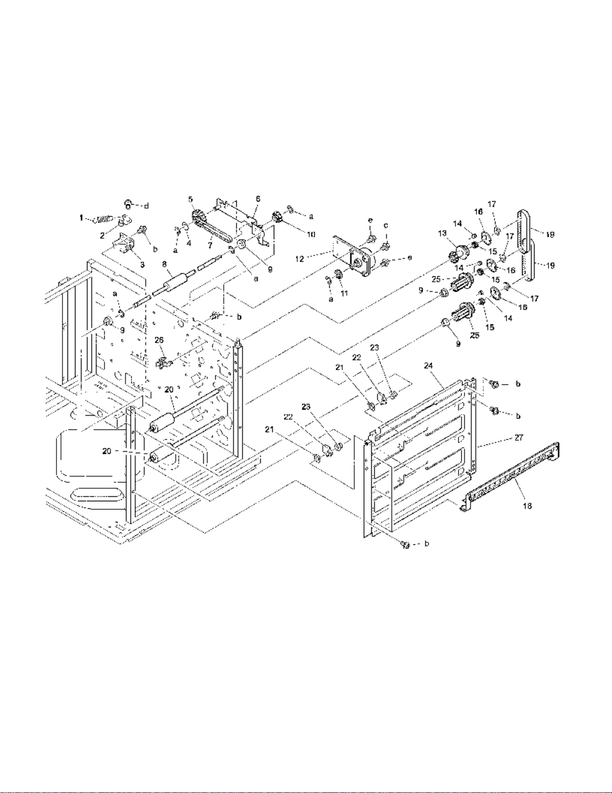
Page 47

REF. PART NUMBER DESCRIPTION
NO.
1 12EA10190 Main support shaft
2 12EA10200 Main support spacer
3 12EA10040 Desk roller/R
4 12RQ10150 Main ADJ plate
5 55GA83060 Inner heater
6 12RQ10171 External cover plate
7 12RQ10160 Wiring fixed plate
8 * Not used
9 12RQ10070 Desk RF stay/left
10 12RQ10031 Main support part/left
11 40AA47181 Slide rail/left
12 049810030 Desk roller/F
13 40AA47171 Slide rail/right
14 12RQ10080 Cassette support plate
15 12RQ10043 Main support part/right
16 12RQ10051 Conveyance guide plate
17 049810020 Desk roller/R
18 12RQ10181 Conveyance guide plate/upper
19 * Not used
20 * Not used
21 12XQ10060 Main RF plate/upper
22 12XQ10090 Fixed plate
23 12XQ10070 Main RF stay/1
24 12XQ10110 External MT part/front
25 12XQ10150 Board protect sheet
26 12XQ10030 PFU driving cover
27 55GA10231 Driving cover/D
HARDWARE
REF.
LTR.
a 00Z194061
b 00Z193161
c 00Z283061
d 00Z521201
e 00Z412351
f 00Z193061
h 00Z924516
j 00Z283081
k 00Z164141
m 00Z164121
n 00Z610401
p 00Z620401
PART
NUMBER
Model DB-208/608 Konica Business Technologies., Inc. Page 3
2nd Edition November, 2000
Page 48

DB-208
Page 4 Konica Business Technologies., Inc. Model DB-208/608
November, 2000 2nd Edition
Page 49

REF. PART NUMBER DESCRIPTION
NO.
1 12XQ-4094 Lift-up driving/upper ass’y
2 40AA-4110 Lift-up motor
3 12RQ77100 Paper feed connecting gear (Z=22)
4 12RQ40034 Paper feed drive casing
5 40AA77400 Lift-up gear/A (Z=57/13)
6 40AA77410 Lift-up gear/B (Z=39/13)
7 40AA77460 Lift-up gear/E (Z=25/13)
8 40AA77420 Lift-up gear/C (Z=34/13)
9 40AA77431 Lift-up gear/D (Z=33)
10 40AA40240 Coupling spring
11 40AA82512 Paper feed solenoid
12 12XQ-9012 Paper feed control board ass’y
13 12XQ-4114 Paper feed lift-up driving/upper ass’y
14 40AA77440 Paper feed connecting gear/E (Z=22)
15 40AA40201 Cassette detecting spring/D
16 40AA40430 Pressure rubber
17 40AA40034 Paper feed drive casing
18 55GA40400 Solenoid MT plate
19 55GA-4140 ADJ plate ass’y
20 40AA40500 Spring guide part
21 55GA-9211 Paper feed detecting board ass’y/2
22 55GA40422 Solenoid stopper claw
23 55GA40440 Spacer
24 12XQ-4150 Lift-up driving board/upper ass’y
HARDWARE
REF.
LTR.
a 00Z670406
b 00Z283061
c 00Z193061
d 00Z253081
e 00Z925130
f 00Z183041
g 00Z670306
h 00Z163061
PART
NUMBER
Model DB-208/608 Konica Business Technologies., Inc. Page 5
2nd Edition November, 2000
Page 50
DB-208
Page 6 Konica Business Technologies., Inc. Model DB-208/608
November, 2000 2nd Edition
Page 51

REF. PART NUMBER DESCRIPTION
NO.
1 40AA47251 Cassette lock spring
2 40AA47230 Cassette rocking arm
3 40AA47220 Cassette lock plate
4 40AA40280 Belt holder/1
5 12RQ77060 Pulley gear/1 (Z=38/14)
6 12RG-4060 Paper feed driving plate ass’y
7 12RQ78010 Paper feed driving belt (L=339)
8 12XQ40050 Conveyance roller/upper
9 466076020 Paper feeding shaft holder
10 12RQ77070 Pulley gear/2 (Z=14/14)
11 12RQ77050 Motor gear (Z=16)
12 55GA80040 Paper feed driving motor
13 12RQ77090 Driving pulley/2 (Z=16/28)
14 540077021 Clutch lock gear (Z=10)
15 40AA40340 Clutch standard gear (Z=17)
16 40AA40210 Clutch protect cover
17 40AA40350 Shaft PS part/black
18 40AA40141 Paper feed guide plate/lower
19 40AA78090 Paper feed driving belt/2 (L=285)
20 40AA40121 Paper conveyance roller
21 40AA40150 Shaft PS part
22 40AA76070 Side feeding shaft holder
23 540076010 Paper feed shaft holder
24 12RQ10181 Conveyance guide plate/upper
25 12RQ77080 Driving pulley/1
26 540047191 Cassette stopper
27 12RQ10051 Conveyance guide plate
HARDWARE
REF.
LTR.
a 00Z670406
b 00Z283061
c 00Z283081
d 00Z194061
e 00Z283101
PART
NUMBER
Model DB-208/608 Konica Business Technologies., Inc. Page 7
2nd Edition November, 2000
Page 52

DB-208
Page 8 Konica Business Technologies., Inc. Model DB-208/608
November, 2000 2nd Edition
Page 53

REF. PART NUMBER DESCRIPTION
NO.
1 12RQ12050 Front fixed cover
2 12RQ12021 Side cover/left
3 12RQ12110 Mount part/rear
4 12XQ12021 Rear cover
5 12RQ10110 Hinge/upper
6 552085510 Photosensor
7 12RQ12012 Side cover/right
8 12RQ10120 Hinge/lower
9 40AA-4702 Universal cassette
10 12XQ12010 Rear holder cover
11 * Not used
12 55GA-4006 Paper feed unit
13 * Not used
14 * Not used
15 * Not used
16 * Not used
17 12RQ40140 Paper feed holding spring
18 12RQ40110 Paper detecting actuator
19 40AA40190 Conveyance driven pin
20 40AA40400 Shaft hold spring
21 40AA40370 Conveyance driven roller
22 40AA40380 Spring hold part/lower
23 12RQ40021 Paper feed door/middle
24 12RQ12080 Paper feed door
25 083020140 Stopper part
26 * Not used
27 * Not used
28 25SA-1080 Ground spring ass’y
HARDWARE
REF.
LTR.
a 00Z194121
b 00Z194061
c 00Z253081
d 00Z283061
e 00Z144102
f 00Z600406
g 00Z144062
h 00Z254081
i 00Z283081
PART
NUMBER
Model DB-208/608 Konica Business Technologies., Inc. Page 9
2nd Edition November, 2000
Page 54

DB-208
Page 10 Konica Business Technologies., Inc. Model DB-208/608
November, 2000 2nd Edition
Page 55

REF. PART NUMBER DESCRIPTION
NO.
1 55GA-4006 Paper feed unit
2 * Not used
3 40AA40230 Oscillating shaft
4 25BA40320 Paper feeding rubber
5 40AA40050 Feeding roller
6 40AA77300 Paper feed idler gear (Z=21)
7 40AA40150 Shaft PS part
8 40AA76040 Feeding shaft holder
9 40AA40041 Paper feeding plate
10 40AA40160 Paper feed driving shaft
11 40AA40082 Contact detecting actuator
12 40AA77360 Paper feed driving gear (Z=16)
13 40AA40073 Paper detecting actuator
14 540040562 Paper supply rubber
15 40AA40060 Conveyance roller
16 40AA40091 Rocking shaft
17 540076010 Paper feed shaft holder
18 40AA77381 Paper feed input gear (Z=16/16)
19 40AA40410 Driving AUX part
20 55GA77710 Rocking gear/C (Z=42)
21 * Not used
22 40AA40330 Double feed PV roller
23 40AA40181 Lever click shaft
24 40AA40100 Double feed MT plate/lower
25 40AA40450 Double feed pressure spring
26 55GA40320 Paper feed base/lower
27 55GA-4022 Reversing roller unit
28 * Not used
29 40AA53551 Fixing ground plate
30 40AA40460 Double feed ADJ plate
31 40AA40470 Double feed RF plate
32 * Not used
33 55GA40012 Paper feed guide sheet/A
34 55GA40020 Paper feed guide seal/A
HARDWARE
REF.
LTR.
a 00Z193061
c 00Z670306
d 00Z670406
f 00Z193101
g 00Z610301
h 00Z620301
i 00Z463101
j 00Z173051
PART
NUMBER
Model DB-208/608 Konica Business Technologies., Inc. Page 11
2nd Edition November, 2000
Page 56

DB-208
Page 12 Konica Business Technologies., Inc. Model DB-208/608
November, 2000 2nd Edition
Page 57

REF. PART NUMBER DESCRIPTION
NO.
1 40AA-4702 Universal cassette
2 40AA47160 Paper detecting spring
3 40AA47080 Paper detecting actuator/upper
4 40AA47070 Paper detecting actuator/middle
5 40AA47061 Paper detecting actuator/lower
6 40AA47104 Paper regulating plate/left
7 40AA47023 Paper regulating plate/front
8 40AA47041 Slide lever
9 40AA47271 Lever pressure spring
10 40AA47032 Paper regulating plate/rear
11 40AA47282 Paper regulating claw
12 540047030 Double feed PV plate
13 40AA47051 Bottom plate
14 40AA47142 Rotary plate
15 40AA47090 Paper detecting actuator/right
16 40AA47181 Slide rail/left
17 40AA12091 Cassette cover
18 40AA47013 Cassette base
19 40AA47150 Ground plate
20 40AA47130 ADJ plate
21 40AA77290 Pinion
22 40AA-4721 Lift-up shaft ass’y
23 40AA47121 Bottom plate lift-up plate
24 40AA47171 Slide rail/right
25 40AA97180 Cassette guide label/U
26 40AA97320 Paper regulating label
27 * Not used
28 682397020 Cassette label
HARDWARE
REF.
LTR.
a 00Z254081
b 00Z283061
c 00Z253081
d 00Z670406
e 00Z193061
f 00Z283081
g 00Z164081
h 00Z263061
PART
NUMBER
Model DB-208/608 Konica Business Technologies., Inc. Page 13
2nd Edition November, 2000
Page 58

DB-208
Page 14 Konica Business Technologies., Inc. Model DB-208/608
November, 2000 2nd Edition
Page 59

REF. PART NUMBER DESCRIPTION
NO.
1 12XQ90010 Paper feed wiring/1
2 12XQ90020 Paper feed wiring/2
Model DB-208/608 Konica Business Technologies., Inc. Page 15
2nd Edition November, 2000
Page 60
DB- 608
Page 16 Konica Business Technologies., Inc. Model DB-208/608
November, 2000 2nd Edition
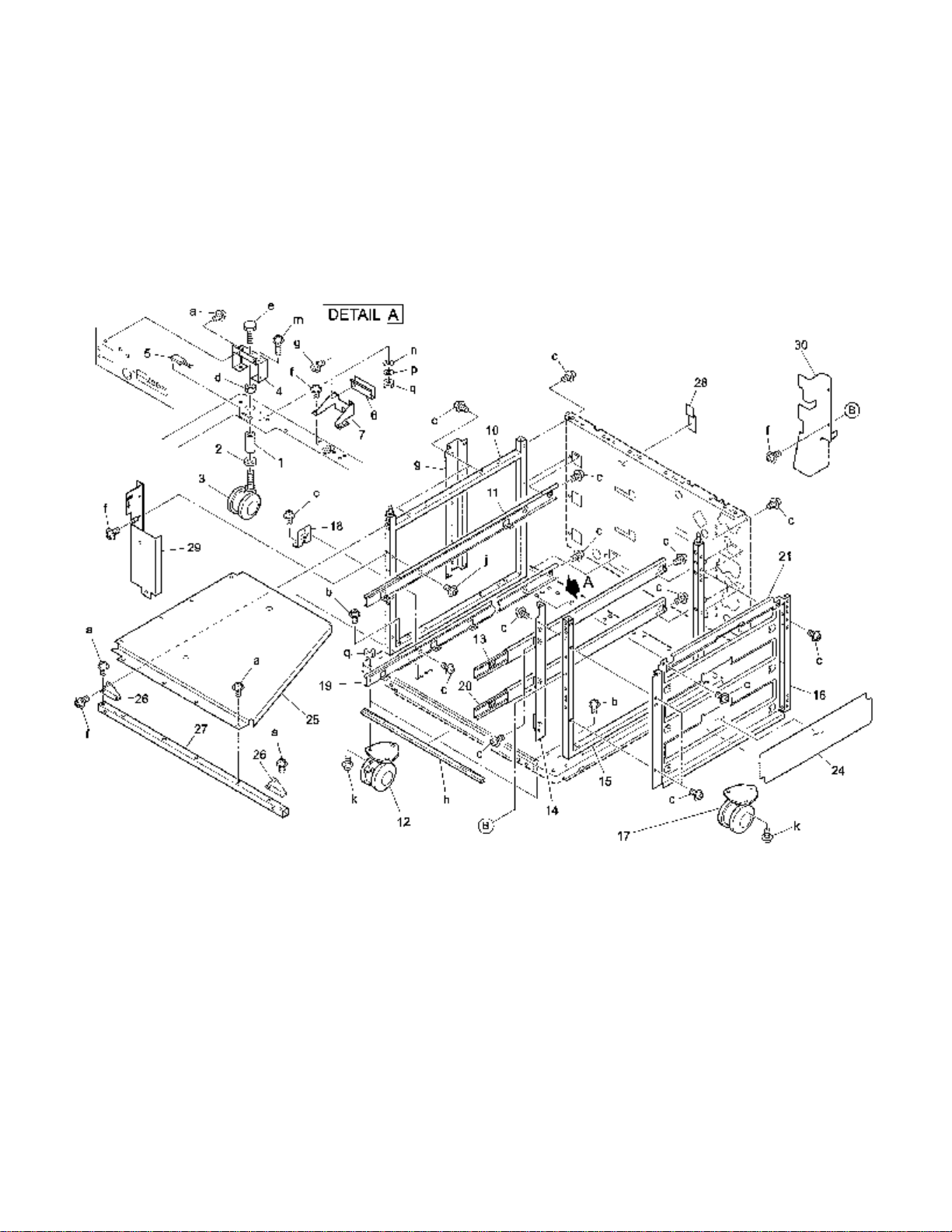
Page 61

REF. PART NUMBER DESCRIPTION
NO.
1 12EA10190 Main support shaft
2 12EA10200 Main support spacer
3 12EA10040 Desk roller/R
4 12RQ10150 Main ADJ plate
5 55GA83060 Inner heater
6 12RQ10171 External cover plate
7 12RQ10160 Wiring fixed plate
8 * Not used
9 12RQ10070 Desk RF stay/left
10 12RQ10031 Main support part/left
11 40AA47181 Slide rail/left
12 049810030 Desk roller/F
13 40AA47171 Slide rail/right
14 12RQ10080 Cassette support plate
15 12RQ10043 Main support part/right
16 12RQ10051 Conveyance guide plate
17 049810020 Desk roller/R
18 12RQ10100 LCT MT plate
19 12RQ47070 LCT slide rail/left
20 12RQ47060 LCT slide rail/right
21 12RQ10181 Conveyance guide plate/upper
22 * Not used
23 * Not used
24 12XU10120 LCT protect sheet
25 12XQ10060 Main RF plate/upper
26 12XQ10090 Fixed plate
27 12XQ10070 Main RF stay/1
28 12XQ10150 Board protect sheet
29 12XU10110 External MT part/front
30 12XU10100 LCT cover plate/right
HARDWARE
REF.
LTR.
PART
NUMBER
a 00Z194061
b 00Z193161
c 00Z283061
d 00Z521201
e 00Z412351
f 00Z193061
g 00Z253061
h 00Z924516
j 00Z283081
k 00Z164141
m 00Z164121
n 00Z610401
p 00Z620401
q 00Z510401
Model DB-208/608 Konica Business Technologies., Inc. Page 17
2nd Edition November, 2000
Page 62

DB- 608
Page 18 Konica Business Technologies., Inc. Model DB-208/608
November, 2000 2nd Edition
Page 63

REF. PART NUMBER DESCRIPTION
NO.
1 12XQ-4094 Lift-up driving/upper ass’y
2 40AA-4110 Lift-up motor
3 12RQ77100 Paper feed connecting gear (Z=22)
4 12RQ40034 Paper feed drive casing
5 40AA77400 Lift-up gear/A (Z=57/13)
6 40AA77410 Lift-up gear/B (Z=39/13)
7 40AA77460 Lift-up gear/E (Z=25/13)
8 40AA77420 Lift-up gear/C (Z=34/13)
9 40AA77431 Lift-up gear/D (Z=33)
10 40AA40240 Coupling spring
11 40AA82512 Paper feed solenoid
12 12XQ-9012 Paper feed control board ass’y
13 12XU-4104 Lift-up driving/L ass’y
14 40AA77440 Paper feed connecting gear (Z=22)
15 40AA40034 Paper feed drive casing
16 40AA40201 Cassette detecting spring/D
17 12RQ77010 Lift-up gear/1 (Z=57/25)
18 12RQ77020 Lift-up gear/2 (Z=25/15)
19 12RQ77030 Lift-up gear/3 (Z=23/22)
20 12RQ77110 Lift-up gear/5 (Z=25/13)
21 40AA40430 Pressure rubber
22 40AA40500 Spring guide part
23 55GA-9201 Paper feed detecting board ass’y/1
24 55GA40400 Solenoid MT plate
25 55GA-4140 ADJ plate ass’y
26 55GA40422 Solenoid stopper claw
27 55GA40440 Spacer
28 12XQ-4150 Lift-up driving board/upper ass’y
HARDWARE
REF.
LTR.
a 00Z670406
b 00Z283061
c 00Z183041
d 00Z193061
e 00Z670306
f 00Z925130
g 00Z253081
h 00Z610301
i 00Z163061
PART
NUMBER
Model DB-208/608 Konica Business Technologies., Inc. Page 19
2nd Edition November, 2000
Page 64

DB- 608
Page 20 Konica Business Technologies., Inc. Model DB-208/608
November, 2000 2nd Edition
Page 65

REF. PART NUMBER DESCRIPTION
NO.
1 40AA47251 Cassette lock spring
2 40AA47230 Cassette rocking arm
3 40AA47220 Cassette lock plate
4 40AA40280 Belt holder/1
5 12RQ77060 Pulley gear/1 (Z=38/14)
6 12RG-4060 Paper feed driving plate ass’y
7 12RQ78010 Paper feed driving belt (L=339)
8 12XQ40050 Conveyance roller/upper
9 466076020 Paper feeding shaft holder
10 12RQ77070 Pulley gear/2 (Z=14/14)
11 12RQ77050 Motor gear (Z=16)
12 55GA80040 Paper feed driving motor
13 12RQ77090 Driving pulley/2 (Z=16/28)
14 540077021 Clutch lock gear (Z=10)
15 40AA40340 Clutch standard gear (Z=17)
16 40AA40210 Clutch protect cover
17 40AA40350 Shaft PS part/black
18 40AA40141 Paper feed guide plate/lower
19 12RQ10051 Conveyance guide plate
20 40AA78090 Paper feed driving belt/2 (L=285)
21 40AA40121 Paper conveyance roller
22 40AA40150 Shaft PS part
23 40AA76070 Side feeding shaft holder
24 540076010 Paper feed shaft holder
25 12RQ10181 Conveyance guide plate/upper
26 540047191 Cassette stopper
27 12RQ77080 Driving pulley/1
HARDWARE
REF.
LTR.
a 00Z670406
b 00Z283061
c 00Z283081
d 00Z283101
e 00Z194061
PART
NUMBER
Model DB-208/608 Konica Business Technologies., Inc. Page 21
2nd Edition November, 2000
Page 66

DB- 608
Page 22 Konica Business Technologies., Inc. Model DB-208/608
November, 2000 2nd Edition
Page 67

REF. PART NUMBER DESCRIPTION
NO.
1 12RQ12050 Front fixed cover
2 12RQ12021 Side cover/left
3 12RQ12110 Mount part/rear
4 12XQ12021 Rear cover
5 12RQ10110 Hinge/upper
6 552085510 Photosensor
7 12RQ12012 Side cover/right
8 12RQ10120 Hinge/lower
9 40AA-4702 Universal cassette
10 12XQ12010 Rear holder cover
11 * Not used
12 55GA-4006 Paper feed unit
13 * Not used
14 * Not used
15 * Not used
16 * Not used
17 12RQ40140 Paper feed holding spring
18 12RQ40110 Paper detecting actuator
19 40AA40190 Conveyance driven pin
20 40AA40400 Shaft hold spring
21 40AA40370 Conveyance driven roller
22 40AA40380 Spring hold part/lower
23 12RQ40021 Paper feed door/middle
24 12RQ12080 Paper feed door
25 083020140 Stopper part
26 * Not used
27 * Not used
28 25SA-1080 Ground spring ass’y
HARDWARE
REF.
LTR.
a 00Z194121
b 00Z194061
c 00Z253081
d 00Z283061
e 00Z144102
f 00Z600406
g 00Z184061
h 00Z254081
i 00Z283081
PART
NUMBER
Model DB-208/608 Konica Business Technologies., Inc. Page 23
2nd Edition November, 2000
Page 68

DB- 608
Page 24 Konica Business Technologies., Inc. Model DB-208/608
November, 2000 2nd Edition
Page 69

REF. PART NUMBER DESCRIPTION
NO.
1 55GA-4006 Paper feed unit
2 * Not used
3 40AA40230 Oscillating shaft
4 25BA40320 Paper feeding rubber
5 40AA40050 Feeding roller
6 40AA77300 Paper feed idler gear (Z=21)
7 40AA40150 Shaft PS part
8 40AA76040 Feeding shaft holder
9 40AA40041 Paper feeding plate
10 40AA40160 Paper feed driving shaft
11 40AA40082 Contact detecting actuator
12 40AA77360 Paper feed driving gear (Z=16)
13 40AA40073 Paper detecting actuator
14 540040562 Paper supply rubber
15 40AA40060 Conveyance roller
16 40AA40091 Rocking shaft
17 540076010 Paper feed shaft holder
18 40AA77381 Paper feed input gear (Z=16/16)
19 40AA40410 Driving AUX part
20 55GA77710 Rocking gear/C (Z=42)
21 * Not used
22 40AA40330 Double feed PV roller
23 40AA40181 Lever click shaft
24 40AA40100 Double feed MT plate/lower
25 40AA40450 Double feed pressure spring
26 55GA40320 Paper feed base/lower
27 55GA-4022 Reversing roller unit
28 * Not used
29 40AA53551 Fixing ground plate
30 40AA40460 Double feed ADJ plate
31 40AA40470 Double feed RF plate
32 * Not used
33 55GA40012 Paper feed guide sheet/A
34 55GA40020 Paper feed guide seal/A
HARDWARE
REF.
LTR.
a 00Z193061
c 00Z670306
d 00Z670406
f 00Z193101
g 00Z610301
h 00Z620301
i 00Z463101
j 00Z173051
PART
NUMBER
Model DB-208/608 Konica Business Technologies., Inc. Page 25
2nd Edition November, 2000
Page 70

DB- 608
Page 26 Konica Business Technologies., Inc. Model DB-208/608
November, 2000 2nd Edition
Page 71

REF. PART NUMBER DESCRIPTION
NO.
1 40AA-4702 Universal cassette
2 40AA47160 Paper detecting spring
3 40AA47080 Paper detecting actuator/upper
4 40AA47070 Paper detecting actuator/middle
5 40AA47061 Paper detecting actuator/lower
6 40AA47104 Paper regulating plate/left
7 40AA47023 Paper regulating plate/front
8 40AA47041 Slide lever
9 40AA47271 Lever pressure spring
10 40AA47032 Paper regulating plate/rear
11 40AA47282 Paper regulating claw
12 540047030 Double feed PV plate
13 40AA47051 Bottom plate
14 40AA47142 Rotary plate
15 40AA47090 Paper detecting actuator/right
16 40AA47181 Slide rail/left
17 40AA12091 Cassette cover
18 40AA47013 Cassette base
19 40AA47150 Ground plate
20 40AA47130 ADJ plate
21 40AA77290 Pinion
22 40AA-4721 Lift-up shaft ass’y
23 40AA47121 Bottom plate lift-up plate
24 40AA47171 Slide rail/right
25 40AA97180 Cassette guide label/U
26 40AA97320 Paper regulating label
27 * Not used
28 682397020 Cassette label
HARDWARE
REF.
LTR.
a 00Z254081
b 00Z283061
c 00Z253081
d 00Z670406
e 00Z193061
f 00Z283081
g 00Z164081
h 00Z263061
PART
NUMBER
Model DB-208/608 Konica Business Technologies., Inc. Page 27
2nd Edition November, 2000
Page 72

DB- 608
Page 28 Konica Business Technologies., Inc. Model DB-208/608
November, 2000 2nd Edition
Page 73

REF. PART NUMBER DESCRIPTION
NO.
1 12RQ47300 Paper guide shaft
2 12RQ47290 Paper guide shaft/A
3 12RQ47040 RF plate
4 12RQ47020 Paper guide plate
5 540047030 Double feed PV plate
6 12RQ47240 Paper guide plate
7 12RQ47030 Paper ADJ plate
8 12RQ47170 Wire idler pulley
9 12RQ47012 Casing
10 12RQ47151 Rear driving wire/front
11 12RQ47140 Rear driving wire/rear
12 12RQ-4711 LCT wire driving shaft ass’y
13 12RQ47080 Wire driving pulley/rear
14 12RQ47100 Pulley fixed part/rear
15 12RQ47060 LCT slide rail/right
16 12RQ12130 LCT cover plate/right
17 12RQ47110 Pulley fixed part/front
18 12RQ47090 Wire driving pulley/front
19 12RQ47230 Wire ADJ part
20 12RQ47310 Driving AUX spring/A
21 564047230 Spring MT plate
22 12RQ47220 Driving AUX spring/B
23 12RQ12120 LCT cover plate/left
24 12RQ47070 LCT slide rail/left
25 564047420 Adjusting cam
26 12RQ12100 LCT cover plate/middle
27 12RQ12040 LCT cover
28 540047200 Paper regulating claw
29 * Not used
30 12RQ47160 AUX wire
31 12RQ47131 Front driving wire/front
32 12RQ47120 Front driving wire/rear
33 12XU47010 LCT protect cover
HARDWARE
REF.
LTR.
PART
NUMBER
a 00Z164081
b 00Z670401
c 00Z253081
f 00Z254101
g 00Z283061
h 00Z254061
i 00Z253101
j 00Z254081
Model DB-208/608 Konica Business Technologies., Inc. Page 29
2nd Edition November, 2000
Page 74

DB- 608
Page 30 Konica Business Technologies., Inc. Model DB-208/608
November, 2000 2nd Edition
Page 75

REF. PART NUMBER DESCRIPTION
NO.
1 12XU90010 Paper feed wiring/1
2 12XQ90020 Paper feed wiring/2
Model DB-208/608 Konica Business Technologies., Inc. Page 31
2nd Edition November, 2000
Page 76

This page left blank intentionally.
Page 32 Konica Business Technologies, Inc. Models DB-208/608
November, 2000 2nd Edition
Page 77

Alphabetical index
PART PAGE REF.
DESCRIPTION NO. NO.
A
ADJ plate . . . . . . . . . . 13 20
ADJ plate . . . . . . . . . . 27 20
ADJ plate ass’y . . . . . . . 5 19
ADJ plate ass’y . . . . . . . 19 25
AUX wire . . . . . . . . . . 29 30
Adjusting cam . . . . . . . 29 25
B
Belt holder/1 . . . . . . . . 7 4
Belt holder/1 . . . . . . . . 21 4
Board protect sheet . . . . 3 25
Board protect sheet . . . . 17 28
Bottom plate . . . . . . . . 13 13
Bottom plate . . . . . . . . 27 13
Bottom plate lift-up plate . . 13 23
Bottom plate lift-up plate . . 27 23
C
Casing . . . . . . . . . . . 29 9
Cassette base . . . . . . . 13 18
Cassette base . . . . . . . 27 18
Cassette cover . . . . . . . 13 17
Cassette cover . . . . . . . 27 17
Cassette detecting spring/D 5 15
Cassette detecting spring/D 19 16
Cassette guide label/U . . . 13 25
Cassette guide label/U . . . 27 25
Cassette label . . . . . . . 13 28
Cassette label . . . . . . . 27 28
Cassette lock plate . . . . . 7 3
Cassette lock plate . . . . . 21 3
Cassette lock spring . . . . 7 1
Cassette lock spring . . . . 21 1
Cassette rocking arm . . . 7 2
Cassette rocking arm . . . 21 2
Cassette stopper . . . . . . 7 26
Cassette stopper . . . . . . 21 26
Cassette support plate . . . 3 14
Cassette support plate . . . 17 14
Clutch lock gear (Z=10) . . 7 14
Clutch lock gear (Z=10) . . 21 14
Clutch protect cover . . . . 7 16
Clutch protect cover . . . . 21 16
Clutch standard gear (Z=17) 7 15
Clutch standard gear (Z=17) 21 15
Contact detecting actuator . 11 11
Contact detecting actuator . 25 11
Conveyance driven pin . . . 9 19
Conveyance driven pin . . . 23 19
Conveyance driven roller . . 9 21
Conveyance driven roller . . 23 21
Conveyance guide plate . . 3 16
Conveyance guide plate . . 7 27
Conveyance guide plate . . 17 16
Conveyance guide plate . . 21 19
Conveyance guide
plate/upper . . . . . . . 3 18
PART PAGE REF.
DESCRIPTION NO. NO.
Conveyance guide
plate/upper . . . . . . . 7 24
Conveyance guide
plate/upper . . . . . . . 17 21
Conveyance guide
plate/upper . . . . . . . 21 25
Conveyance roller . . . . . 11 15
Conveyance roller . . . . . 25 15
Conveyance roller/upper . . 7 8
Conveyance roller/upper . . 21 8
Coupling spring . . . . . . . 5 10
Coupling spring . . . . . . . 19 10
D
Desk RF stay/left . . . . . . 3 9
Desk RF stay/left . . . . . . 17 9
Desk roller/F . . . . . . . . 3 12
Desk roller/F . . . . . . . . 17 12
Desk roller/R . . . . . . . . 3 3
Desk roller/R . . . . . . . . 3 17
Desk roller/R . . . . . . . . 17 3
Desk roller/R . . . . . . . . 17 17
Double feed ADJ plate . . . 11 30
Double feed ADJ plate . . . 25 30
Double feed MT plate/lower 11 24
Double feed MT plate/lower 25 24
Double feed PV plate . . . . 13 12
Double feed PV plate . . . . 27 12
Double feed PV plate . . . . 29 5
Double feed PV roller . . . . 11 22
Double feed PV roller . . . . 25 22
Double feed RF plate . . . . 11 31
Double feed RF plate . . . . 25 31
Double feed pressure spring 11 25
Double feed pressure spring 25 25
Driving AUX part . . . . . . 11 19
Driving AUX part . . . . . . 25 19
Driving AUX spring/A . . . . 29 20
Driving AUX spring/B . . . . 29 22
Driving cover/D . . . . . . . 3 27
Driving pulley/1 . . . . . . . 7 25
Driving pulley/1 . . . . . . . 21 27
Driving pulley/2 (Z=16/28) . 7 13
Driving pulley/2 (Z=16/28) . 21 13
E
External MT part/front . . . 3 24
External MT part/front . . . 17 29
External cover plate . . . . 3 6
External cover plate . . . . 17 6
F
Feeding roller . . . . . . . . 11 5
Feeding roller . . . . . . . . 25 5
Feeding shaft holder . . . . 11 8
Feeding shaft holder . . . . 25 8
Fixed plate . . . . . . . . . 3 22
Fixed plate . . . . . . . . . 17 26
PART PAGE REF.
DESCRIPTION NO. NO.
Fixing ground plate . . . . . 25 29
Fixing ground plate . . . . . 11 29
Front driving wire/front . . . 29 31
Front driving wire/rear . . . 29 32
Front fixed cover . . . . . . 9 1
Front fixed cover . . . . . . 23 1
G
Ground plate . . . . . . . . 13 19
Ground plate . . . . . . . . 27 19
Ground spring ass’y . . . . 9 28
Ground spring ass’y . . . . 23 28
H
Hinge/lower . . . . . . . . . 9 8
Hinge/lower . . . . . . . . . 23 8
Hinge/upper . . . . . . . . . 9 5
Hinge/upper . . . . . . . . . 23 5
I
Inner heater . . . . . . . . . 3 5
Inner heater . . . . . . . . . 17 5
L
LCT MT plate . . . . . . . . 17 18
LCT cover . . . . . . . . . . 29 27
LCT cover plate/left . . . . . 29 23
LCT cover plate/middle . . . 29 26
LCT cover plate/right . . . . 17 30
LCT cover plate/right . . . . 29 16
LCT protect cover . . . . . . 29 33
LCT protect sheet . . . . . . 17 24
LCT slide rail/left . . . . . . 17 19
LCT slide rail/left . . . . . . 29 24
LCT slide rail/right . . . . . 17 20
LCT slide rail/right . . . . . 29 15
LCT wire driving shaft ass’y . 29 12
Lever click shaft . . . . . . . 11 23
Lever click shaft . . . . . . . 25 23
Lever pressure spring . . . . 13 9
Lever pressure spring . . . . 27 9
Lift-up driving board/upper
ass’y . . . . . . . . . . 5 24
Lift-up driving board/upper
ass’y . . . . . . . . . . 19 28
Lift-up driving/L ass’y . . . . 19 13
Lift-up driving/upper ass’y . . 5 1
Lift-up driving/upper ass’y . . 19 1
Lift-up gear/1 (Z=57/25) . . 19 17
Lift-up gear/2 (Z=25/15) . . 19 18
Lift-up gear/3 (Z=23/22) . . 19 19
Lift-up gear/5 (Z=25/13) . . 19 20
Lift-up gear/A (Z=57/13) . . 5 5
Lift-up gear/A (Z=57/13) . . 19 5
Lift-up gear/B (Z=39/13) . . 5 6
Lift-up gear/B (Z=39/13) . . 19 6
Models DB-208/608 Konica Business Technologies, Inc. Page 33
2nd Edition November, 2000
Page 78

PART PAGE REF.
DESCRIPTION NO. NO.
Lift-up gear/C (Z=34/13) . . 5 8
Lift-up gear/C (Z=34/13) . . 19 8
Lift-up gear/D (Z=33) . . . . 5 9
Lift-up gear/D (Z=33) . . . . 19 9
Lift-up gear/E (Z=25/13) . . 5 7
Lift-up gear/E (Z=25/13) . . 19 7
Lift-up motor . . . . . . . . 5 2
Lift-up motor . . . . . . . . 19 2
Lift-up shaft ass’y . . . . . . 13 22
Lift-up shaft ass’y . . . . . . 27 22
M
Main ADJ plate . . . . . . . 3 4
Main ADJ plate . . . . . . . 17 4
Main RF plate/upper . . . . 3 21
Main RF plate/upper . . . . 17 25
Main RF stay/1 . . . . . . . 3 23
Main RF stay/1 . . . . . . . 17 27
Main support part/left . . . . 3 10
Main support part/left . . . . 17 10
Main support part/right . . . 3 15
Main support part/right . . . 17 15
Main support shaft . . . . . 3 1
Main support shaft . . . . . 17 1
Main support spacer . . . . 3 2
Main support spacer . . . . 17 2
Motor gear (Z=16) . . . . . 7 11
Motor gear (Z=16) . . . . . 21 11
Mount part/rear . . . . . . . 9 3
Mount part/rear . . . . . . . 23 3
O
Oscillating shaft . . . . . . . 25 3
Oscillating shaft . . . . . . . 11 3
P
PFU driving cover . . . . . . 3 26
Paper ADJ plate . . . . . . 29 7
Paper conveyance roller . . 7 20
Paper conveyance roller . . 21 21
Paper detecting actuator . . 9 18
Paper detecting actuator . . 11 13
Paper detecting actuator . . 23 18
Paper detecting actuator . . 25 13
Paper detecting
actuator/lower . . . . . . 13 5
Paper detecting
actuator/lower . . . . . . 27 5
Paper detecting
actuator/middle . . . . . 13 4
Paper detecting
actuator/middle . . . . . 27 4
Paper detecting actuator/right 13 15
Paper detecting actuator/right 27 15
Paper detecting
actuator/upper . . . . . 13 3
Paper detecting
actuator/upper . . . . . 27 3
Paper detecting spring . . . 13 2
Paper detecting spring . . . 27 2
Paper feed base/lower . . . 11 26
Paper feed base/lower . . . 25 26
PART PAGE REF.
DESCRIPTION NO. NO.
Paper feed connecting gear
(Z=22) . . . . . . . . . 5 3
Paper feed connecting gear
(Z=22) . . . . . . . . . 19 3
Paper feed connecting gear
(Z=22) . . . . . . . . . 19 14
Paper feed connecting
gear/E (Z=22) . . . . . 5 14
Paper feed control board
ass’y . . . . . . . . . 5 12
Paper feed control board
ass’y . . . . . . . . . 19 12
Paper feed detecting board
ass’y/2 . . . . . . . . 5 21
Paper feed detecting board
ass’y/1 . . . . . . . . 19 23
Paper feed door . . . . . . 9 24
Paper feed door . . . . . . 23 24
Paper feed door/middle . . 9 23
Paper feed door/middle . . 23 23
Paper feed drive casing . . 5 4
Paper feed drive casing . . 5 17
Paper feed drive casing . . 19 4
Paper feed drive casing . . 19 15
Paper feed driving belt
(L=339) . . . . . . . . 7 7
Paper feed driving belt
(L=339) . . . . . . . . 21 7
Paper feed driving belt/2
(L=285) . . . . . . . . 7 19
Paper feed driving belt/2
(L=285) . . . . . . . . 21 20
Paper feed driving gear
(Z=16) . . . . . . . . . 11 12
Paper feed driving gear
(Z=16) . . . . . . . . . 25 12
Paper feed driving motor . 7 12
Paper feed driving motor . 21 12
Paper feed driving plate ass’y 7 6
Paper feed driving plate ass’y 21 6
Paper feed driving shaft . . 11 10
Paper feed driving shaft . . 25 10
Paper feed guide plate/lower 7 18
Paper feed guide plate/lower 21 18
Paper feed guide seal/A . . 11 34
Paper feed guide seal/A . . 25 34
Paper feed guide sheet/A . 11 33
Paper feed guide sheet/A . 25 33
Paper feed holding spring . 9 17
Paper feed holding spring . 23 17
Paper feed idler gear (Z=21) 11 6
Paper feed idler gear (Z=21) 25 6
Paper feed input gear
(Z=16/16) . . . . . . . 11 18
Paper feed input gear
(Z=16/16) . . . . . . . 25 18
Paper feed lift-up
driving/upper ass’y . . 5 13
Paper feed shaft holder . . 7 23
Paper feed shaft holder . . 11 17
Paper feed shaft holder . . 21 24
Paper feed shaft holder . . 25 17
Paper feed solenoid . . . . 5 11
Paper feed solenoid . . . . 19 11
Paper feed unit . . . . . . 9 12
Paper feed unit . . . . . . 11 1
Paper feed unit . . . . . . 23 12
Paper feed unit . . . . . . 25 1
Paper feed wiring/1 . . . . 15 1
PART PAGE REF.
DESCRIPTION NO. NO.
Paper feed wiring/1 . . . . 31 1
Paper feed wiring/2 . . . . 15 2
Paper feed wiring/2 . . . . 31 2
Paper feeding plate . . . . 11 9
Paper feeding plate . . . . 25 9
Paper feeding rubber . . . 11 4
Paper feeding rubber . . . 25 4
Paper feeding shaft holder 7 9
Paper feeding shaft holder 21 9
Paper guide plate . . . . . 29 4
Paper guide plate . . . . . 29 6
Paper guide shaft . . . . . 29 1
Paper guide shaft/A . . . . 29 2
Paper regulating claw . . . 13 11
Paper regulating claw . . . 27 11
Paper regulating claw . . . 29 28
Paper regulating label . . . 13 26
Paper regulating label . . . 27 26
Paper regulating plate/front 13 7
Paper regulating plate/front 27 7
Paper regulating plate/left . 13 6
Paper regulating plate/left . 27 6
Paper regulating plate/rear 13 10
Paper regulating plate/rear 27 10
Paper supply rubber . . . . 11 14
Paper supply rubber . . . . 25 14
Photosensor . . . . . . . . 9 6
Photosensor . . . . . . . . 23 6
Pinion . . . . . . . . . . . 13 21
Pinion . . . . . . . . . . . 27 21
Pressure rubber . . . . . . 5 16
Pressure rubber . . . . . . 19 21
Pulley fixed part/front . . . 29 17
Pulley fixed part/rear . . . . 29 14
Pulley gear/1 (Z=38/14) . . 7 5
Pulley gear/1 (Z=38/14) . . 21 5
Pulley gear/2 (Z=14/14) . . 7 10
Pulley gear/2 (Z=14/14) . . 21 10
R
RF plate . . . . . . . . . . 29 3
Rear cover . . . . . . . . . 9 4
Rear cover . . . . . . . . . 23 4
Rear driving wire/front . . . 29 10
Rear driving wire/rear . . . 29 11
Rear holder cover . . . . . 9 10
Rear holder cover . . . . . 23 10
Reversing roller unit . . . . 11 27
Reversing roller unit . . . . 25 27
Rocking gear/C (Z=42) . . 11 20
Rocking gear/C (Z=42) . . 25 20
Rocking shaft . . . . . . . 11 16
Rocking shaft . . . . . . . 25 16
Rotary plate . . . . . . . . 13 14
Rotary plate . . . . . . . . 27 14
S
Shaft PS part . . . . . . . 7 21
Shaft PS part . . . . . . . 11 7
Shaft PS part . . . . . . . 21 22
Shaft PS part . . . . . . . 25 7
Shaft PS part/black . . . . 21 17
Shaft PS part/black . . . . 7 17
Shaft hold spring . . . . . . 9 20
Shaft hold spring . . . . . . 23 20
Page 34 Konica Business Technologies, Inc. Models DB-208/608
November, 2000 2nd Edition
Page 79

PART PAGE REF.
DESCRIPTION NO. NO.
Side cover/left . . . . . . . . 9 2
Side cover/left . . . . . . . . 23 2
Side cover/right . . . . . . . 9 7
Side cover/right . . . . . . . 23 7
Side feeding shaft holder . . 7 22
Side feeding shaft holder . . 21 23
Slide lever . . . . . . . . . . 13 8
Slide lever . . . . . . . . . . 27 8
Slide rail/left . . . . . . . . . 3 11
Slide rail/left . . . . . . . . . 13 16
Slide rail/left . . . . . . . . . 17 11
Slide rail/left . . . . . . . . . 27 16
Slide rail/right . . . . . . . . 3 13
Slide rail/right . . . . . . . . 13 24
Slide rail/right . . . . . . . . 17 13
Slide rail/right . . . . . . . . 27 24
PART PAGE REF.
DESCRIPTION NO. NO.
Solenoid MT plate . . . . . 5 18
Solenoid MT plate . . . . . 19 24
Solenoid stopper claw . . . 5 22
Solenoid stopper claw . . . 19 26
Spacer . . . . . . . . . . . 5 23
Spacer . . . . . . . . . . . 19 27
Spring MT plate . . . . . . 29 21
Spring guide part . . . . . 5 20
Spring guide part . . . . . 19 22
Spring hold part/lower . . . 9 22
Spring hold part/lower . . . 23 22
Stopper part . . . . . . . . 9 25
Stopper part . . . . . . . . 23 25
PART PAGE REF.
DESCRIPTION NO. NO.
U
Universal cassette . . . . . 9 9
Universal cassette . . . . . 13 1
Universal cassette . . . . . 23 9
Universal cassette . . . . . 27 1
W
Wire ADJ part . . . . . . . 29 19
Wire driving pulley/front . . 29 18
Wire driving pulley/rear . . 29 13
Wire idler pulley . . . . . . 29 8
Wiring fixed plate . . . . . 3 7
Wiring fixed plate . . . . . 17 7
Models DB-208/608 Konica Business Technologies, Inc. Page 35
2nd Edition November, 2000
Page 80

This page left blank intentionally.
Page 36 Konica Business Technologies, Inc. Models DB-208/608
November, 2000 2nd Edition
Page 81

Numerical index
Retail price list
PART PAGE REF.SUGGESTED
NUMBER NO. NO. RETAIL
049810020 . . . . 3 17
049810020 . . . . 17 17
049810030 . . . . 3 12
049810030 . . . . 17 12
083020140 . . . . 9 25
083020140 . . . . 23 25
12EA10040 . . . . 3 3
12EA10040 . . . . 17 3
12EA10190 . . . . 3 1
12EA10190 . . . . 17 1
12EA10200 . . . . 3 2
12EA10200 . . . . 17 2
12RG-4060 . . . . 7 6
12RG-4060 . . . . 21 6
12RQ-4711 . . . . 29 12
12RQ10031 . . . 3 10
12RQ10031 . . . 17 10
12RQ10043 . . . 3 15
12RQ10043 . . . 17 15
12RQ10051 . . . 3 16
12RQ10051 . . . 7 27
12RQ10051 . . . 17 16
12RQ10051 . . . 21 19
12RQ10070 . . . 3 9
12RQ10070 . . . 17 9
12RQ10080 . . . 3 14
12RQ10080 . . . 17 14
12RQ10100 . . . 17 18
12RQ10110 . . . 9 5
12RQ10110 . . . 23 5
12RQ10120 . . . 9 8
12RQ10120 . . . 23 8
12RQ10150 . . . 3 4
12RQ10150 . . . 17 4
12RQ10160 . . . 3 7
12RQ10160 . . . 17 7
12RQ10171 . . . 3 6
12RQ10171 . . . 17 6
12RQ10181 . . . 3 18
12RQ10181 . . . 7 24
12RQ10181 . . . 17 21
12RQ10181 . . . 21 25
12RQ12012 . . . 9 7
12RQ12012 . . . 23 7
12RQ12021 . . . 9 2
12RQ12021 . . . 23 2
12RQ12040 . . . 29 27
12RQ12050 . . . 9 1
12RQ12050 . . . 23 1
12RQ12080 . . . 9 24
12RQ12080 . . . 23 24
12RQ12100 . . . 29 26
12RQ12110 . . . 9 3
12RQ12110 . . . 23 3
12RQ12120 . . . 29 23
12RQ12130 . . . 29 16
12RQ40021 . . . 9 23
12RQ40021 . . . 23 23
12RQ40034 . . . 5 4
12RQ40034 . . . 19 4
12RQ40110 . . . 9 18
12RQ40110 . . . 23 18
12RQ40140 . . . 9 17
12RQ40140 . . . 23 17
PART PAGE REF.SUGGESTED
NUMBER NO. NO. RETAIL
12RQ47012 . . . 29 9
12RQ47020 . . . 29 4
12RQ47030 . . . 29 7
12RQ47040 . . . 29 3
12RQ47060 . . . 17 20
12RQ47060 . . . 29 15
12RQ47070 . . . 17 19
12RQ47070 . . . 29 24
12RQ47080 . . . 29 13
12RQ47090 . . . 29 18
12RQ47100 . . . 29 14
12RQ47110 . . . . 29 17
12RQ47120 . . . 29 32
12RQ47131 . . . 29 31
12RQ47140 . . . 29 11
12RQ47151 . . . 29 10
12RQ47160 . . . 29 30
12RQ47170 . . . 29 8
12RQ47220 . . . 29 22
12RQ47230 . . . 29 19
12RQ47240 . . . 29 6
12RQ47290 . . . 29 2
12RQ47300 . . . 29 1
12RQ47310 . . . 29 20
12RQ77010 . . . 19 17
12RQ77020 . . . 19 18
12RQ77030 . . . 19 19
12RQ77050 . . . 7 11
12RQ77050 . . . 21 11
12RQ77060 . . . 7 5
12RQ77060 . . . 21 5
12RQ77070 . . . 7 10
12RQ77070 . . . 21 10
12RQ77080 . . . 7 25
12RQ77080 . . . 21 27
12RQ77090 . . . 7 13
12RQ77090 . . . 21 13
12RQ77100 . . . 5 3
12RQ77100 . . . 19 3
12RQ77110 . . . . 19 20
12RQ78010 . . . 7 7
12RQ78010 . . . 21 7
12XQ-4094 . . . . 5 1
12XQ-4094 . . . . 19 1
12XQ-4114 . . . . 5 13
12XQ-4150 . . . . 5 24
12XQ-4150 . . . . 19 28
12XQ-9012 . . . . 5 12
12XQ-9012 . . . . 19 12
12XQ10030 . . . . 3 26
12XQ10060 . . . . 3 21
12XQ10060 . . . . 17 25
12XQ10070 . . . . 3 23
12XQ10070 . . . . 17 27
12XQ10090 . . . . 3 22
12XQ10090 . . . . 17 26
12XQ10110 . . . . 3 24
12XQ10150 . . . . 3 25
12XQ10150 . . . . 17 28
12XQ12010 . . . . 9 10
12XQ12010 . . . . 23 10
12XQ12021 . . . . 9 4
12XQ12021 . . . . 23 4
12XQ40050 . . . . 7 8
PART PAGE REF.SUGGESTED
NUMBER NO. NO. RETAIL
12XQ40050 . . . . 21 8
12XQ90010 . . . . 15 1
12XQ90020 . . . . 15 2
12XQ90020 . . . . 31 2
12XU-4104 . . . . 19 13
12XU10100 . . . . 17 30
12XU10110 . . . . 17 29
12XU10120 . . . . 17 24
12XU47010 . . . . 29 33
12XU90010 . . . . 31 1
25BA40320 . . . . 11 4
25BA40320 . . . . 25 4
25SA-1080 . . . . 9 28
25SA-1080 . . . . 23 28
40AA-4110 . . . . 5 2
40AA-4110 . . . . 19 2
40AA-4702 . . . . 9 9
40AA-4702 . . . . 13 1
40AA-4702 . . . . 23 9
40AA-4702 . . . . 27 1
40AA-4721 . . . . 13 22
40AA-4721 . . . . 27 22
40AA12091 . . . . 13 17
40AA12091 . . . . 27 17
40AA40034 . . . . 5 17
40AA40034 . . . . 19 15
40AA40041 . . . . 11 9
40AA40041 . . . . 25 9
40AA40050 . . . . 11 5
40AA40050 . . . . 25 5
40AA40060 . . . . 11 15
40AA40060 . . . . 25 15
40AA40073 . . . . 11 13
40AA40073 . . . . 25 13
40AA40082 . . . . 11 11
40AA40082 . . . . 25 11
40AA40091 . . . . 11 16
40AA40091 . . . . 25 16
40AA40100 . . . . 11 24
40AA40100 . . . . 25 24
40AA40121 . . . . 7 20
40AA40121 . . . . 21 21
40AA40141 . . . . 7 18
40AA40141 . . . . 21 18
40AA40150 . . . . 7 21
40AA40150 . . . . 11 7
40AA40150 . . . . 21 22
40AA40150 . . . . 25 7
40AA40160 . . . . 11 10
40AA40160 . . . . 25 10
40AA40181 . . . . 11 23
40AA40181 . . . . 25 23
40AA40190 . . . . 9 19
40AA40190 . . . . 23 19
40AA40201 . . . . 5 15
40AA40201 . . . . 19 16
40AA40210 . . . . 7 16
40AA40210 . . . . 21 16
40AA40230 . . . . 11 3
40AA40230 . . . . 25 3
40AA40240 . . . . 5 10
40AA40240 . . . . 19 10
40AA40280 . . . . 7 4
40AA40280 . . . . 21 4
Model DB-208/608 Konica Business Technologies, Inc. Page 37
2nd Edition November, 2000
Page 82

PART PAGE REF.SUGGESTED
NUMBER NO. NO. RETAIL
40AA40330 . . . . 11 22
40AA40330 . . . . 25 22
40AA40340 . . . . 7 15
40AA40340 . . . . 21 15
40AA40350 . . . . 7 17
40AA40350 . . . . 21 17
40AA40370 . . . . 9 21
40AA40370 . . . . 23 21
40AA40380 . . . . 9 22
40AA40380 . . . . 23 22
40AA40400 . . . . 9 20
40AA40400 . . . . 23 20
40AA40410 . . . . 11 19
40AA40410 . . . . 25 19
40AA40430 . . . . 5 16
40AA40430 . . . . 19 21
40AA40450 . . . . 11 25
40AA40450 . . . . 25 25
40AA40460 . . . . 11 30
40AA40460 . . . . 25 30
40AA40470 . . . . 11 31
40AA40470 . . . . 25 31
40AA40500 . . . . 5 20
40AA40500 . . . . 19 22
40AA47013 . . . . 13 18
40AA47013 . . . . 27 18
40AA47023 . . . . 13 7
40AA47023 . . . . 27 7
40AA47032 . . . . 13 10
40AA47032 . . . . 27 10
40AA47041 . . . . 13 8
40AA47041 . . . . 27 8
40AA47051 . . . . 13 13
40AA47051 . . . . 27 13
40AA47061 . . . . 13 5
40AA47061 . . . . 27 5
40AA47070 . . . . 13 4
40AA47070 . . . . 27 4
40AA47080 . . . . 13 3
40AA47080 . . . . 27 3
40AA47090 . . . . 13 15
40AA47090 . . . . 27 15
40AA47104 . . . . 13 6
40AA47104 . . . . 27 6
40AA47121 . . . . 13 23
40AA47121 . . . . 27 23
40AA47130 . . . . 13 20
40AA47130 . . . . 27 20
40AA47142 . . . . 13 14
40AA47142 . . . . 27 14
40AA47150 . . . . 13 19
40AA47150 . . . . 27 19
40AA47160 . . . . 13 2
PART PAGE REF.SUGGESTED
NUMBER NO. NO. RETAIL
40AA47160 . . . . 27 2
40AA47171 . . . . 3 13
40AA47171 . . . . 13 24
40AA47171 . . . . 17 13
40AA47171 . . . . 27 24
40AA47181 . . . . 3 11
40AA47181 . . . . 13 16
40AA47181 . . . . 17 11
40AA47181 . . . . 27 16
40AA47220 . . . . 7 3
40AA47220 . . . . 21 3
40AA47230 . . . . 7 2
40AA47230 . . . . 21 2
40AA47251 . . . . 7 1
40AA47251 . . . . 21 1
40AA47271 . . . . 13 9
40AA47271 . . . . 27 9
40AA47282 . . . . 13 11
40AA47282 . . . . 27 11
40AA53551 . . . . 11 29
40AA53551 . . . . 25 29
40AA76040 . . . . 11 8
40AA76040 . . . . 25 8
40AA76070 . . . . 7 22
40AA76070 . . . . 21 23
40AA77290 . . . . 13 21
40AA77290 . . . . 27 21
40AA77300 . . . . 11 6
40AA77300 . . . . 25 6
40AA77360 . . . . 11 12
40AA77360 . . . . 25 12
40AA77381 . . . . 11 18
40AA77381 . . . . 25 18
40AA77400 . . . . 5 5
40AA77400 . . . . 19 5
40AA77410 . . . . 5 6
40AA77410 . . . . 19 6
40AA77420 . . . . 5 8
40AA77420 . . . . 19 8
40AA77431 . . . . 5 9
40AA77431 . . . . 19 9
40AA77440 . . . . 5 14
40AA77440 . . . . 19 14
40AA77460 . . . . 5 7
40AA77460 . . . . 19 7
40AA78090 . . . . 7 19
40AA78090 . . . . 21 20
40AA82512 . . . . 5 11
40AA82512 . . . . 19 11
40AA97180 . . . . 13 25
40AA97180 . . . . 27 25
40AA97320 . . . . 13 26
40AA97320 . . . . 27 26
PART PAGE REF.SUGGESTED
NUMBER NO. NO. RETAIL
466076020 . . . . 7 9
466076020 . . . . 21 9
540040562 . . . . 11 14
540040562 . . . . 25 14
540047030 . . . . 13 12
540047030 . . . . 27 12
540047030 . . . . 29 5
540047191 . . . . 7 26
540047191 . . . . 21 26
540047200 . . . . 29 28
540076010 . . . . 7 23
540076010 . . . . 11 17
540076010 . . . . 21 24
540076010 . . . . 25 17
540077021 . . . . 7 14
540077021 . . . . 21 14
552085510 . . . . 9 6
552085510 . . . . 23 6
55GA-4006 . . . 9 12
55GA-4006 . . . 11 1
55GA-4006 . . . 23 12
55GA-4006 . . . 25 1
55GA-4022 . . . 11 27
55GA-4022 . . . 25 27
55GA-4140 . . . 5 19
55GA-4140 . . . 19 25
55GA-9201 . . . 19 23
55GA-9211 . . . 5 21
55GA10231 . . . 3 27
55GA40012 . . . 11 33
55GA40012 . . . 25 33
55GA40020 . . . 11 34
55GA40020 . . . 25 34
55GA40320 . . . 11 26
55GA40320 . . . 25 26
55GA40400 . . . 5 18
55GA40400 . . . 19 24
55GA40422 . . . 5 22
55GA40422 . . . 19 26
55GA40440 . . . 5 23
55GA40440 . . . 19 27
55GA77710 . . . 11 20
55GA77710 . . . 25 20
55GA80040 . . . 7 12
55GA80040 . . . 21 12
55GA83060 . . . 3 5
55GA83060 . . . 17 5
564047230 . . . . 29 21
564047420 . . . . 29 25
682397020 . . . . 13 28
682397020 . . . . 27 28
Page 38 Konica Business Technologies, Inc. Model DB-208/608
November, 2000 2nd Edition
 Loading...