

Page 1

SERVICE MANUAL
Models
DB-209/210/409/410
MARCH 2001
CSM-DB209/210
KONICA BUSINESS TECHNOLOGIES, INC.
Page 2

Page 3

DB-209/210/409/410
SERVICE MANUAL
MARCH 2001
Used on Konica Models
7020, 7025, 7030, and 7035
Page 4

IMPORTANT NOTICE
Because of the possible hazards to an inexperienced
person servicing this equipment, as well as the risk of
damage to the equipment, Konica Business Technologies strongly recommends that all servicing be performed by Konica-trained service technicians only.
Changes may have been made to this equipment to
improve its performance after this service manual was
printed. Accordingly, Konica Business Technologies,
Inc., makes no representations or warranties, either
expressed or implied, that the information contained in
this service manual is complete or accurate. It is understood that the user of this manual must assume all risks
or personal injury and/or damage to the equipment while
servicing the equipment for which this service manual
is intended.
Corporate Publications Department
© 2001, KONICA BUSINESS TECHNOLOGIES, INC.
All rights reserved.
Printed in U.S.A.
Page 5

CONTENTS
DB-209/210/409/410
DB-209/210
1. OUTLINE
DB-209/210 PRODUCT SPECIFICATIONS ................... 1
[1] Type ................................................................ 1
[2] Functions ......................................................... 1
[3] Machine data................................................... 1
[4] Maintenance.................................................... 1
[5] Machine environment ...................................... 1
CENTER CROSS SECTION ........................................... 2
DRIVE SYSTEM DIAGRAM ............................................ 3
2. UNIT EXPLANATION
PAPER FEED SECTION................................................. 4
[1] Composition .................................................... 4
[2] Mechanisms .................................................... 4
[3] Paper feed and no paper detection
control .............................................................. 5
[4] Tray up and down control................................ 7
[5] Paper size detection control ............................ 8
[6] Control of paper-level detection ...................... 9
[7] Jam detection control ...................................... 9
3. DISASSEMBLY/ASSEMBLY
DISASSEMBLY/ASSEMBLY......................................... 10
[1] Removing and reinstalling paper
feed tray ........................................................ 10
[2] Removing and reinstalling the paper
feed unit ......................................................... 10
[3] Replacing the feed roller rubber and
double feed prevention rubber/upper ............. 11
[4] Repacing the double feed prevention
rubber/lower .................................................. 12
3. DISASSEMBLY/ASSEMBLY
DISASSEMBLY/ASSEMBLY ..........................................21
[1] Removing and reinstalling the paper
feed tray ......................................................... 21
[2] Removing and reinstalling the paper
feed unit.......................................................... 21
[3] Replacing the feed roller rubber and
double feed prevention rubber/upper .............22
[4] Replacing the double feed prevention
rubber/lower ................................................... 23
[5] Replacing the wires ........................................ 24
4. DB-209/210/409/410 DIAGRAMS
DB-209/210 ELECTRICAL PARTS LAYOUT ................ 27
DB-409/410 ELECTRICAL PARTS LAYOUT ................ 28
DB-209/210 CONNECTOR LAYOUT ............................ 29
DB-409/410 CONNECTOR LAYOUT ............................ 30
DB-209/DB-409 TIMING CHART (8.5X11, LIFE SIZE, 3
COPIES, FEED FROM TRAY3 .................................... 31
DB-209/210/409/410 OVERALL WIRING DIAGRAM ....33
DB-409/410
1. OUTLINE
DB-409/410 PRODUCT SPECIFICATIONS ................. 13
[1] Type .............................................................. 13
[2] Functions ....................................................... 13
[3] Machine data................................................. 13
[4] Maintenance.................................................. 13
[5] Machine environment .................................... 13
CENTER CROSS SECTION ......................................... 14
DRIVE SYSTEM DIAGRAM .......................................... 15
2. UNIT EXPLANATION
PAPER FEED SECTION............................................... 16
[1] Composition .................................................. 16
[2] Mechanisms .................................................. 16
[3] Paper feed and no paper detection
control............................................................ 17
[4] Tray up and down control.............................. 18
[5] Paper size detection control .......................... 19
[6] Control of paper-level detection .................... 20
iii
Page 6

DB-209/210/409/410
Blank
iv
Page 7

SAFETY PRECAUTIONS
SAFETY PRECAUTIONS
Installation Environment
Safety considerations usually are directed toward
machine design and the possibility of human error. In
addition, the environment in which a machine is operated must not be overlooked as a potential safety
hazard.
Most electrical equipment is safe when installed in a
normal environment. However, if the environment is
different from what most people consider to be normal, it is conceivable that the combination of the
machine and the room air could present a hazardous
combination. This is because heat (such as from
fusing units) and electrical arcs (which can occur
inside switches) have the ability to ignite flammable
substances, including air.
When installing a machine, check to see if there
is anything nearby which suggests that a potential hazard might exist. For example, a laboratory
might use organic compounds which, when they
evaporate, make the room air volatile. Potentially dangerous conditions might be seen or smelled. The
presence of substances such as cleaners, paint thinners, gasoline, alcohol, solvents, explosives, or similar items should be cause for concern.
If conditions such as these exist, take appropriate
action, such as one of the following suggestions.
effect may be caused by altering any aspect of the
machine’s design. Such changes have the potential
of degrading product performance and reducing
safety margins.
For these reasons, installation of any modification not
specifically authorized by Konica Business Machines
U.S.A., Inc., is strictly prohibited.
The following list of prohibited actions is not all-inclusive, but demonstrates the intent of this policy.
• Using an extension cord or any unauthorized
power cord adapter.
• Installing any fuse whose rating and physical size
differs from that originally installed.
• Using wire, paper clips, solder, etc., to replace or
eliminate any fuse (including temperature fuses).
• Removing (except for replacement) any air filter.
• Defeating the operation of relays by any means
(such as wedging paper between contacts).
• Causing the machine to operate in a fashion other
than as it was designed.
• Making any change which might have a chance
of defeating built-in safety features.
• Using any unspecified replacement parts.
• Determine that the environment is controlled
(such as through the use of an exhaust hood) so
that an offending substance or its fumes cannot
reach the machine.
• Remove the offending substance.
• Install the machine in a different location.
The specific remedy will vary from site to site, but the
principles remain the same. To avoid the risk of injury
or damage, be alert for changes in the environment
when performing subsequent service on any machine, and take appropriate action.
Unauthorized Modifications
Konica copiers have gained a reputation for being
reliable products. This has been attained by a combination of outstanding design and a knowledgeable
service force.
The design of the copier is extremely important. It is
the design process that determines tolerances and
safety margins for mechanical, electrical, and electronic aspects. It is not reasonable to expect individuals not involved in product engineering to know what
General Safety Guidelines
This copier has been examined in accordance with
the laws pertaining to various product safety regulations prior to leaving the manufacturing facility to
protect the operators and service personnel from
injury. However, as with any operating device, components will break down through the wear-and-tear of
everyday use, as will additional safety discrepancies
be discovered. For this reason, it is important that the
technician periodically performs safety checks on the
copier to maintain optimum reliability and safety.
The following checks, not all-inclusive, should be
made during each service call:
CAUTION: Avoid injury. Ensure that the copier is
disconnected from its power source before continuing.
• Look for sharp edges, burrs, and damage on all
external covers and copier frame.
• Inspect all cover hinges for wear (loose or broken).
• Inspect cables for wear, frays, or pinched areas.
v
Page 8

SAFETY PRECAUTIONS
• Ensure that the power cord insulation is not damaged (no exposed electrical conductors).
• Ensure that the power cord is properly mounted
to the frame by cord clamps.
• Check the continuity from the round lug (GND) of
the power cord to the frame of the copier -- ensure
continuity. An improperly grounded machine can
cause an electrically-charged machine frame.
Safeguards During Service Calls
Confirm that all screws, parts, and wiring which are
removed during maintenance are installed in their
original positions.
• When disconnecting connectors, do not pull the
wiring, particularly on AC line wiring and high
voltage parts.
• Do not route the power cord where it is likely to
be stepped on or crushed.
• Carefully remove all toner and dirt adhering to any
electrical units or electrodes.
• After part replacement or repair work, route the
wiring in such a way that it does not contact any
burrs or sharp edges.
• Do not make any adjustments outside of the
specified range.
Applying Isopropyl Alcohol
Care should be exercised when using isopropyl alcohol, due to its flammability. When using alcohol to
clean parts, observe the following precautions:
• Remove power from the equipment.
• Use alcohol in small quantities to avoid spillage
or puddling. Any spillage should be cleaned up
with rags and disposed of properly.
• Be sure that there is adequate ventilation.
• Allow a surface which has been in contact with
alcohol to dry for a few minutes to ensure that the
alcohol has evaporated completely before applying power or installing covers.
Summary
It is the responsibility of every technician to use professional skills when servicing Konica products. There
are no short cuts to high-quality service. Each copier
must be thoroughly inspected with respect to safety
considerations as part of every routine service call.
The operability of the copier, and more importantly,
the safety of those who operate or service the copier,
are directly dependent upon the conscientious effort
of each and every technician.
Remember...when performing service calls, use good
judgement (have a watchful eye) to identify safety
hazards or potential safety hazards that may be present, and correct these problem areas as they are
identified -- the safety of those who operate the copier
as well as those who service the copier depend on it!
vi
Page 9

DB-209/210 PRODUCT SPECIFICATIONS
[1] Type
Type: Tray paper feed
(Front loading)
[2] Functions
Paper size:
U.S.A. Europe and others
11 × 17, 8.5 × 14,
8.5 × 11R, 8.5 × 11,
5.5 × 8.5, F4, A3,
A4R, A4, A5R
Paper type: 16 lb. to 24 lb. high quality
Maximum
Paper capacity: 500 sheets x 2 trays
A3, B4, A4, A4R, B5,
A5R, 11 × 17,
8.5 × 11, 8.5 × 11R,
F4
paper
(22 lb.)
DB-209/210/409/410
[3] Machine data
Power: DC24V/5V (supplied from
main body)
Power consumption: Max.40VA (When the PTC
heater is not in use.)
Weight: Approximately 56 lb.
Machine
Dimensions: Length 22.8 in.
Depth 23.4 in.
Height 12.2 in.
[4] Maintenance
Maintenance: Same as main body
[5] Machine operation environment
Temperature: 50 to 86°F
Humidity: 20 to 80%RH
Note : Specifications are subject to change without
notice.
1
Page 10
DB-209/210/409/410
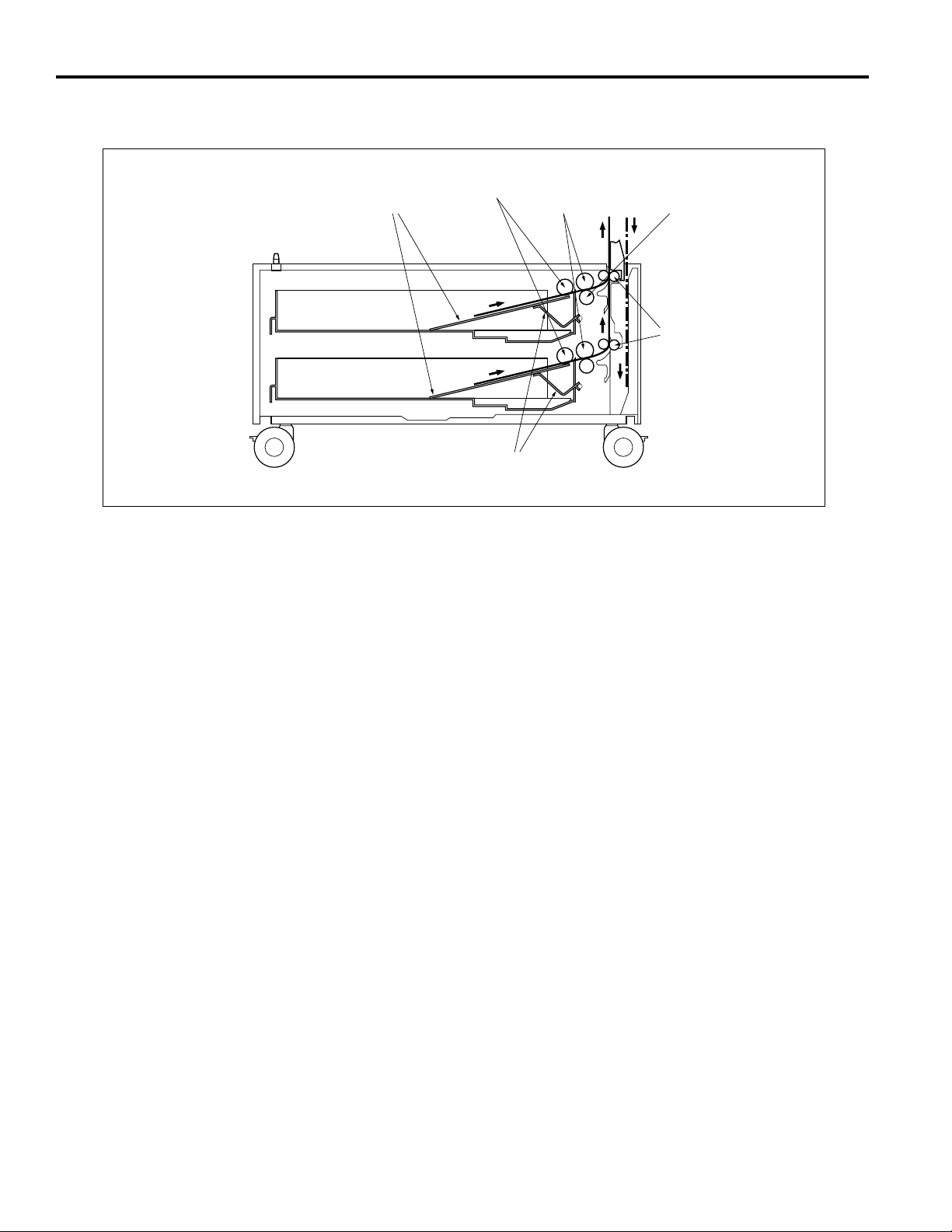
CENTER CROSS SECTION
Paper lift-up plates
Feed rollers
Paper lowering levers
Double feed prevention
rollers/upper
Double feed prevention
roller/lower
Conveyance
rollers
2
Page 11
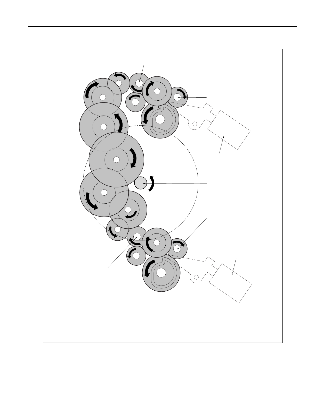
DRIVE SYSTEM DIAGRAM
Conveyance roller
DB-209/210/409/410
Double feed prevention roller/upper
1st paper feed SD (upper) (SD101)
Conveyance roller
Paper feed motor (M100)
Double feed prevention roller/lower
1st paper feed SD (lower) (SD102)
3
Page 12
DB-209/210/409/410
PAPER FEED UNIT
[1] Composition
Double feed prevention roller/upper
Double feed prevention roller/lower
Feed roller
Size setting units
[2] Mechanisms
Mechanism Method
Paper feed Paper feed roller
Paper lifting Paper lift-up plate
Double feed Torque limiter
prevention
Tray loading Front loading
1st paper feed Paper feed SD
Feed roller
Jam processing Release of pressure on
double feed prevention roller
No paper detect Photosensor
Paper size detect Size setting unit
Paper conveyance Roller conveyance
Conveyance drive Gears
Paper feed door
4
Page 13
DB-209/210/409/410
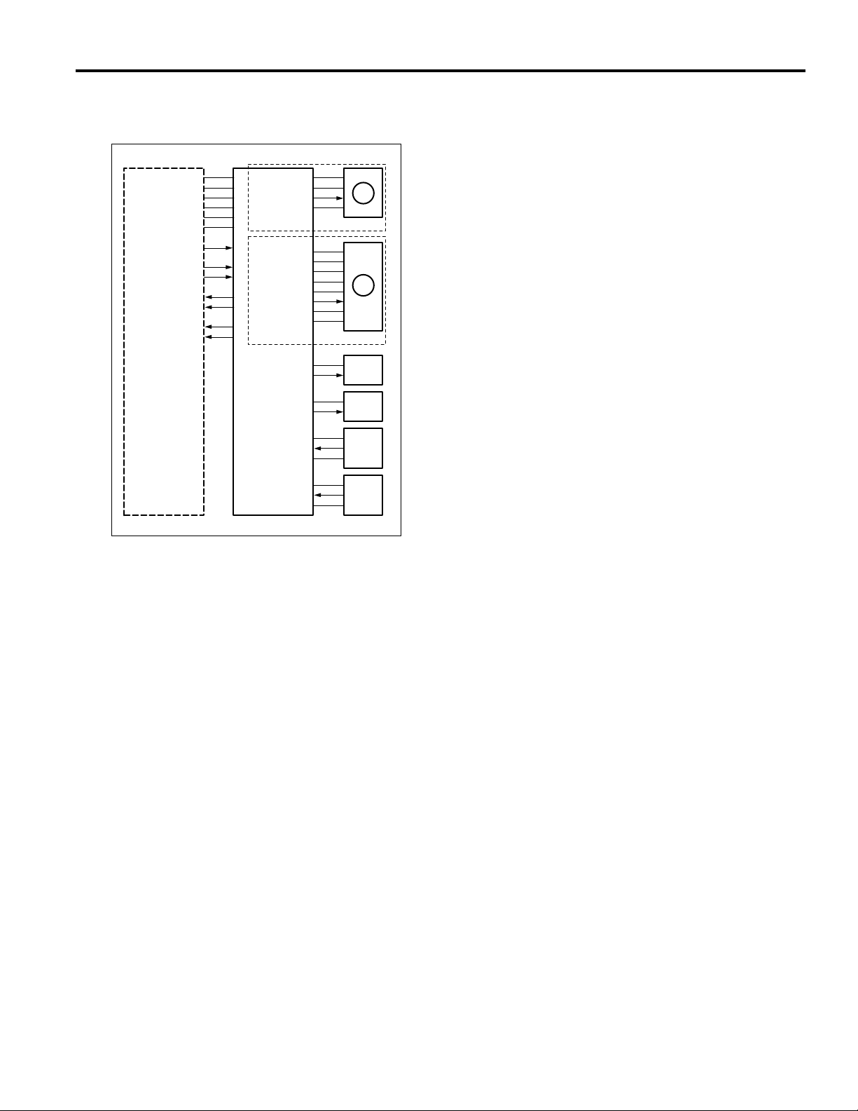
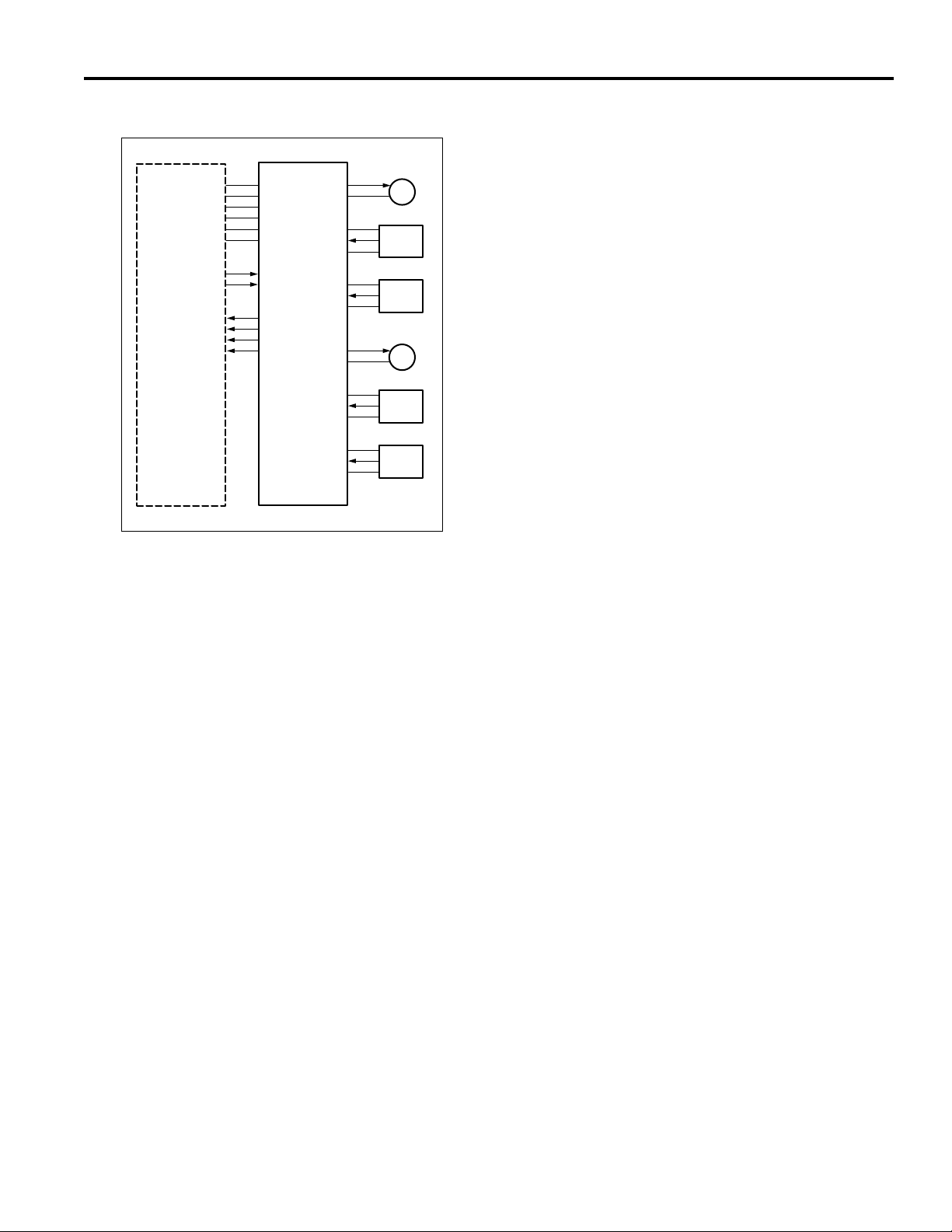
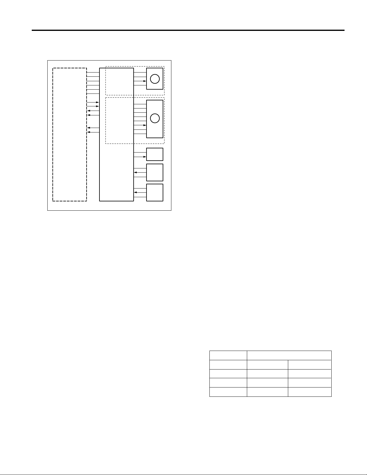
[3] Paper feed and no paper detection
control
24VDC
24VDC
PGND
PGND
5VDC
SGND
M100 CONT
SD101 CONT
SD102 CONT
PS103
PS108
DB SELECT1
DB SELECT2
MAIN BODY
Paper feed is carried out by transmitting the drive of the
M100 (Paper feed motor) to the upper and lower paper
feed rollers and to the feed rollers. When feed starts,
SD101 (1st. paper feed SD (upper)) or SD102 (1st. paper
feed SD (lower)) raises and lowers the feed roller and
contacts the paper.
M100 CONT
M100 LD
M100 CLK
M100 CONT
SD101 DRIVE
SD102 DRIVE
PS103 SIG
PS108 SIG
PFUDB
24VDC
PGND
24VDC
24VDC
P.GND
5VDC
S.GND
24VDC
24VDC
SGND
5VDC
SGND
5VDC
M100
EM
DB-209
M100
DB-210
SD101
SD102
PS103
PS108
1. Operation
a. Paper feed operation timing (upper tray)
(1) 1st. sheet start
A specified time after start-button is turned ON
(2) 2nd. sheet start
A specified time after 1st. sheet SD101 is turned ON
(3) OFF timing
A specified time after SD101 is turned ON
b. Paper feed operation timing (lower tray)
(1) 1st. sheet start
A specified time after start-button is turned ON
(2) 2nd. sheet start
A specified time after 1st. sheet SD102 is turned ON
(3) OFF timing
A specified time after SD102 is turned ON
c. No paper detection
If paper in the tray is used up, PS103 or PS 108 goes
OFF and the no paper detection signal of each tray is
sent to the main body via the PFUDB.
Drive of the M100, SD101 and SD102 is carried out by
PFUDB (PFU drive board)and controlled by the main
body.
No paper detection is carried out with PS103 (No paper
detect PS (upper)) and PS108 (No paper detect PS
(lower)) and controlled by the main body via the PFUDB.
5
Page 14

DB-209/210/409/410
2. Signals
a. Input signals
(1) PS103 SIG (PS103 -> PFUDB)
Upper tray paper/no paper detection signal
[H] :no paper
[L] :with paper
(2) PS108 SIG (PS108 -> PFUDB)
Lower tray paper/no paper detection signal
[H] :no paper
[L] :with paper
(3) SD101 CONT (MAIN BODY -> PFUDB)
SD101 ON/OFF control signal from main body
[H] :OFF
[L] :ON
(4) SD102 CONT (MAIN BODY -> PFUDB)
SD102 ON/OFF control signal from main body
[H] :OFF
[L] :ON
b. Output signals
(1) M100 CONT (PFUDB -> M100)
M100 drive control signal
[H] : M100 OFF
[L] :M100 ON
(2) M100 CLK (PFUDB -> M100)
M100 revolution control board clock signal
(3) SD101 (PFUDB -> SD101)
SD101 drive control signal
[H] :OFF
[L] :ON
(4) SD102 DRIVE (PFUDB -> SD102)
SD102 drive control signal
[H] :OFF
[L] :ON
(5) PS103 (PFUDB -> MAIN BODY)
Upper tray paper/no paper detection signal sent to
main body
(6) PS108 (PFUDB -> MAIN BODY)
Lower tray paper/no paper detection signal sent to
main body
(7) DB SELECT (PFUDB -> MAIN BODY)
DB Type identification signals sent to main body
Signal
DB DB-SELECT 1 DB-SELECT 0
DB-209/210 H L
Not connected H
Undefined L L
H
6
Page 15
DB-209/210/409/410
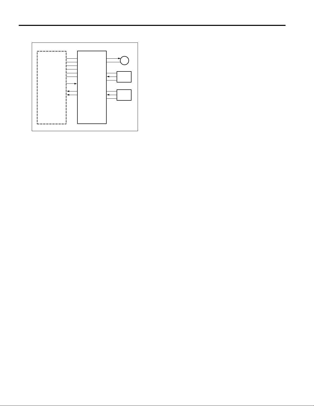
[4] Tray up and down control
24VDC
24VDC
PGND
PGND
5VDC
SGND
M101 CONT
M102 CONT
PS101
PS102
PS106
PS107
MAIN BODY PFUDB
M101 DRIVE
24VDC
SGND
PS101
5VDC
SGND
PS102
5VDC
M102 DRIVE
24VDC
SGND
PS106
5VDC
SGND
PS107
5VDC
M101
PS101
PS102
M102
PS106
PS107
2. Signals
a. Input signals
(1) PS101 (PS101 -> PFUDB)
Upper tray detect signal
By turning ON with [L] showing, M101 raises the
paper in the upper tray.
(2) PS106 (PS106 -> PFUDB)
Lower tray detect signal
By turning on with [L] showing, M102 raises the paper
in the lower tray.
(3) PS102 (PS102 -> PFUDB)
Upper tray paper upper limit detect signal
When the upper tray is raised and arrives at the upper
limit position, the signal becomes [H] and M101 is
turned off.
(4) PS107 (PS107 -> PFUDB)
Lower tray paper upper limit detect sensor
When the lower tray is raised and arrives at the upper
limit position, the signal becomes [H] and M102 is
turned off.
1. Operation
When the paper feed tray of each level is set, PS101
(Tray detect PS (upper)) and PS106 (Tray detect PS
(lower)) detect the tray, M101 (Tray motor 1) and
M102 (Tray motor 2) turn on and lift the base plate in
the tray. When the tray is lifted, PS102 (Upper limit
detect PS (upper)) and PS 107 (Upper limit detect PS
(lower)) detect the paper upper limit and turn ON,
M101 and M102 turn off and the raising of the tray is
completed.
The down operation of the trays is performed
mechanically.
(5) M101 CONT (MAIN BODY -> PFUDB)
M101 ON/OFF control signal from main body
(6) M102 CONT (MAIN BODY -> PFUDB)
M102 ON/OFF control signal from main body
b. Output signals
(1) M101 DRIVE (PFUDB -> M101)
M101 drive control signal
[L] :M101 ON
[H] :M101 OFF
(2) M102 DRIVE (PFUDB -> M102)
M102 drive control signal
[L] :M102 ON
[H] :M102 OFF
(3) PS101 (PFUDB -> MAIN BODY)
Upper tray detect signal sent to main body
(4) PS102 (PFUDB -> MAIN BODY)
Upper tray paper upper limit detect signal sent to
main body
(5) PS106 (PFUDB -> MAIN BODY)
Lower tray detect signal sent to main body
(6) PS107 (PFUDB -> MAIN BODY)
Lower tray paper upper limit detect signal sent to
main body
7
Page 16
DB-209/210/409/410
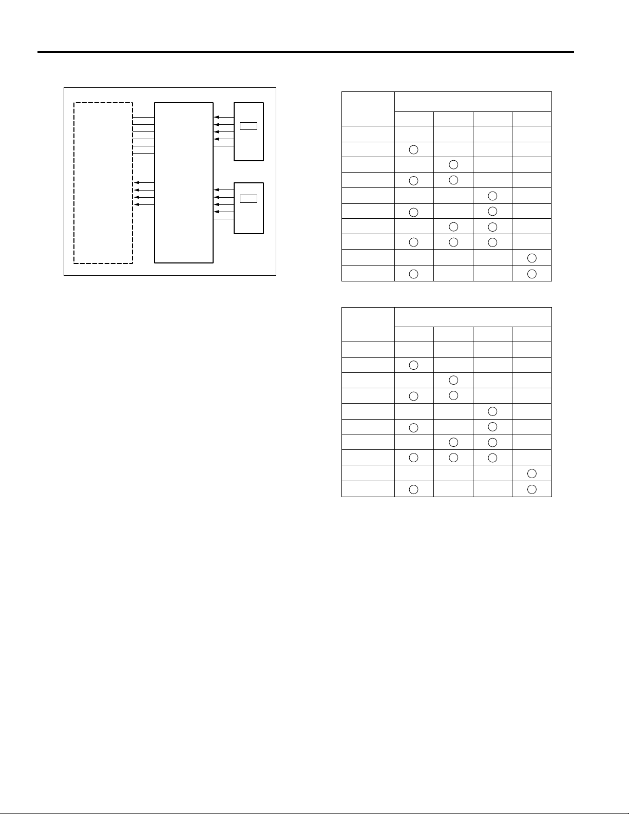
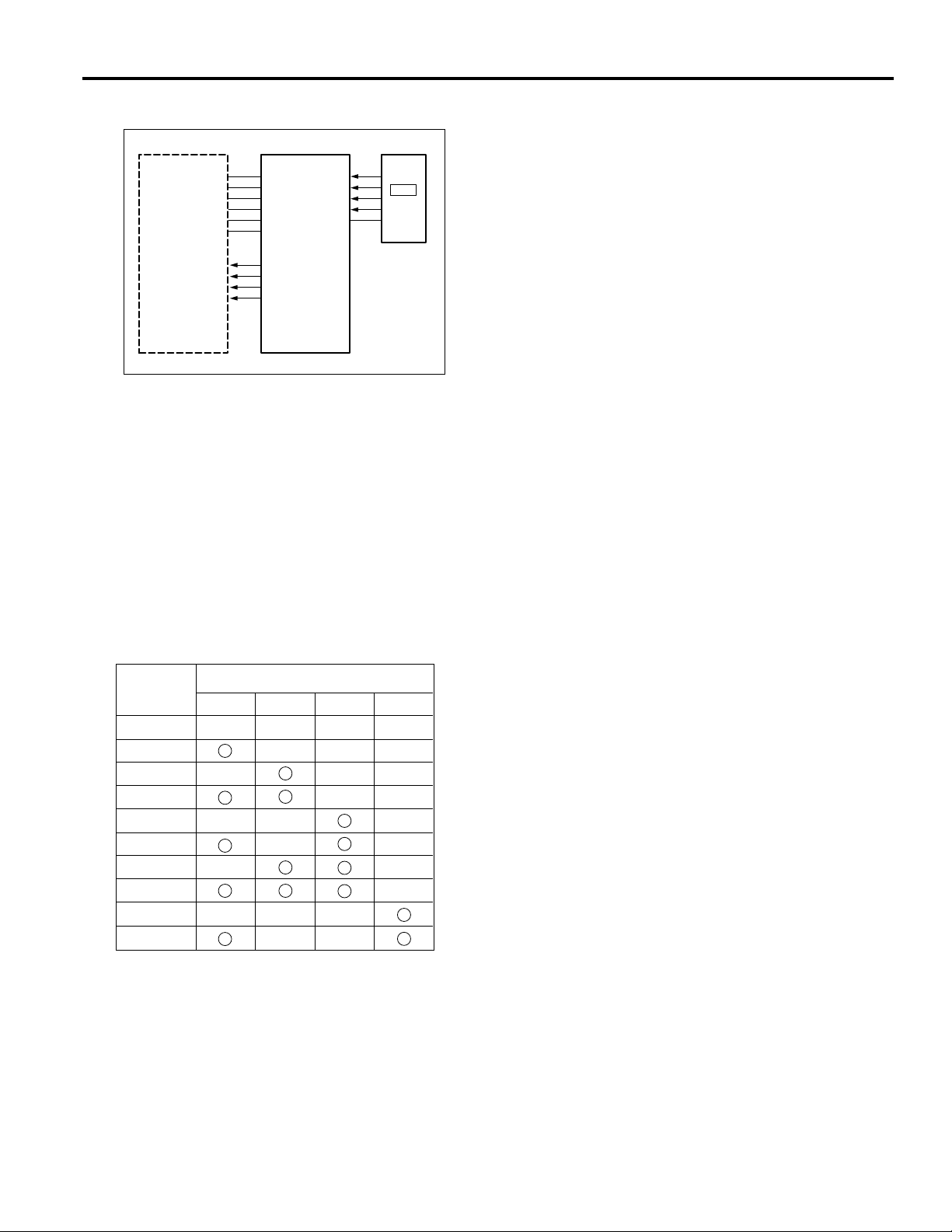
[5] Paper size detection control
24VDC
24VDC
PGND
PGND
5VDC
SGND
SIZE D
SIZE C
SIZE B
SIZE A
MAIN BODY
Tray paper size is detected in the main body by a signal
sent from SDB1(size detection board1) and SDB2 (size
detection board2) via the PFUDB (PFU drive board).
1. Operation
a. Tray paper size detection
Paper size for either tray is set by SW1 and SW2
above SDB1 and SDB2 and the PFUDB detects the
switch signal corresponding to the position of SW1
and SW2.
The relation between switch signal and paper size is
as follows.
U SIZE D
U SIZE C
U SIZE B
U SIZE A
U SIZE SELECT
L SIZE D
L SIZE C
L SIZE B
L SIZE A
L SIZE SELECT
PFUDB
SW1
SDB1
SW2
SDB2
For U.S.A.
Paper size
(Label display
order)
11 x 17
A5R
A4
A4R
A3
F4
5.5 x 8.5
8.5 x 11
8.5 x 11R
8.5 x 14
For Europe
Paper size
(Label display
order)
11 x 17
B5
B4
A5R
A4
A4R
A3
F4
11
11R
Switch signal
SIZE A SIZE B SIZE C SIZE D
Switch signal
SIZE A SIZE B SIZE C SIZE D
2. Signals
a. Input signals
(1) U SIZE A - D (SDB1 -> PFUDB)
Upper tray paper size detect signal
(2) U SIZE A - D (SDB2 -> PFUDB)
Lower tray paper size detect signal
b. Output signal
(1) SIZE A - D (PFUDB -> MAIN BODY)
Paper size detection signal sent to main body
8
Page 17
DB-209/210/409/410
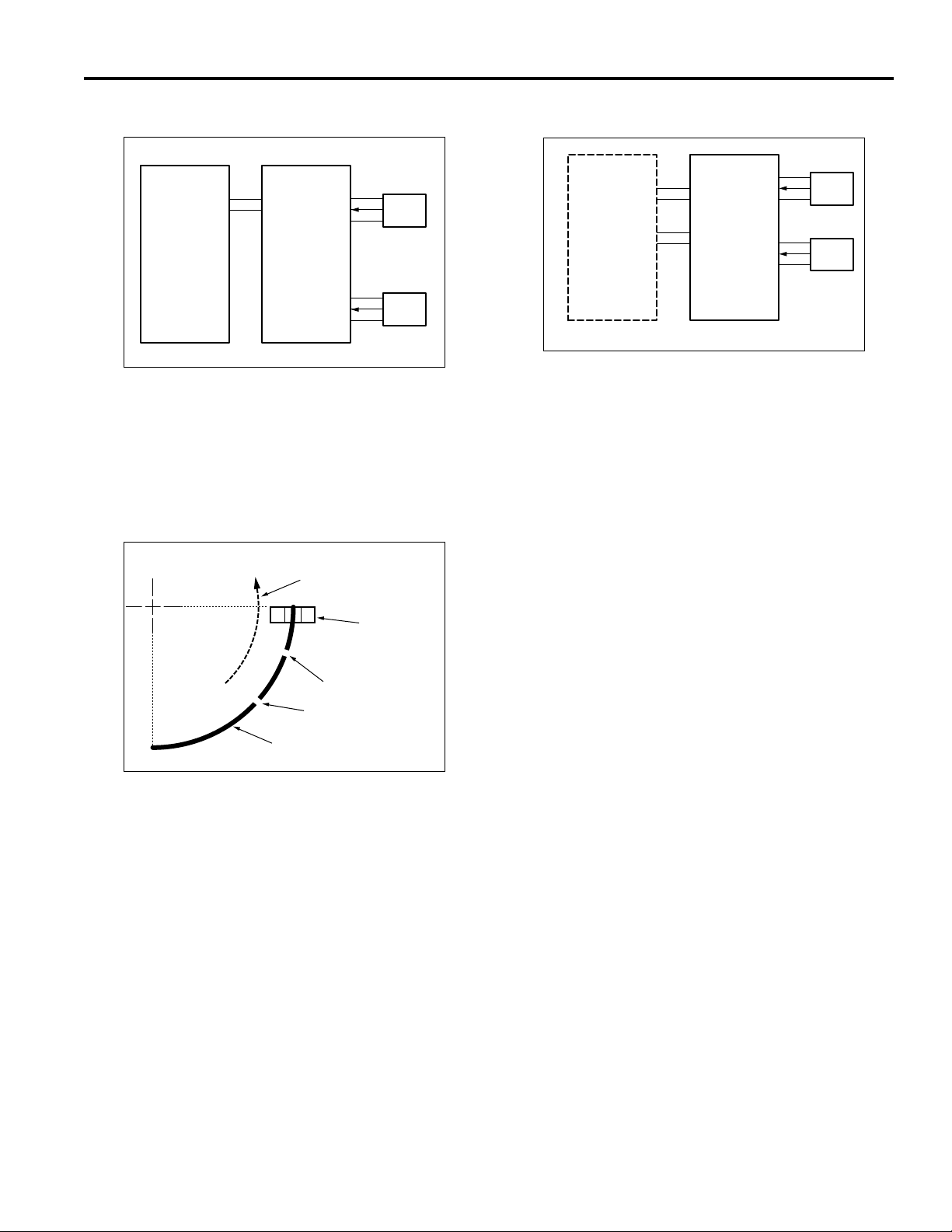
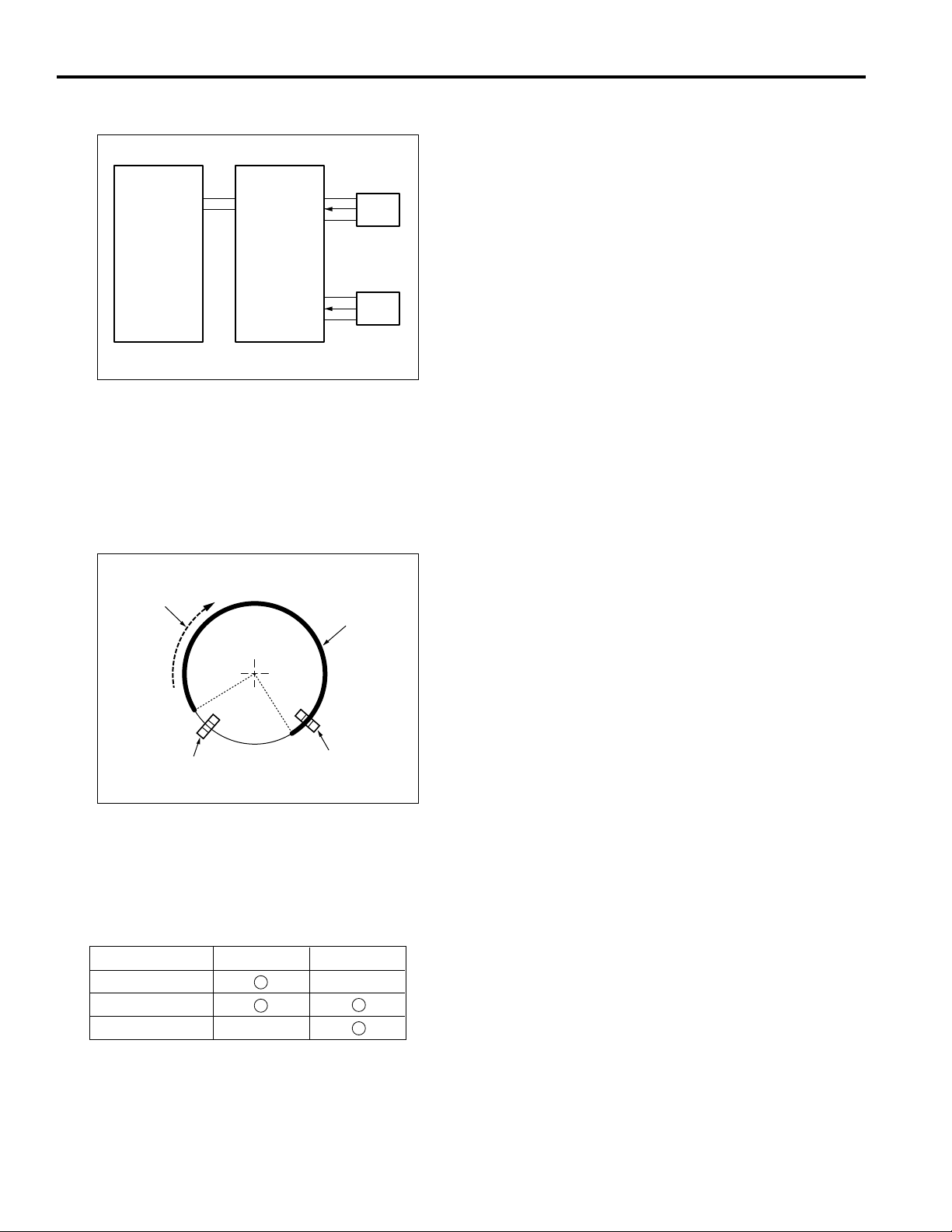
[6] Control of paper-level detection
SGND
5VDC
NAIN BODY
After the trays have been set in the machine, paper level is
detected by PS101 (tray detect sensor PS (upper)) and
PS106 (tray detect sensor PS (lower)).
As the paper level in tray runs low, the actuator at the rear
part of the tray gradually rotates as illustrated below. The
level is detected by the number of times the sensor goes
ON/OFF (the number of slits detected).
View looking from rear
Actuator
1. Operation
SGND
PS101
5VDC
SGND
PS106
5VDC
PFUDB
Direction of rotation
when the paper
lifting plate rises.
Tray detect
sensor
Slit 1
Slit 2
PS101
PS106
[7] Jam detection control
PFUDB
SGND
PS104
5VDC
SGND
PS105
5VDC
5VDC
SGND
PS104
PS105
MAIN BODY
1. Operation
Jam detection control is performed by the main body
when it has judged the changes in the PS104 (jam
detect PS1) and PS105 (jam detecting PS2)
detection signals. If the ON detection signal of each
sensor does not change after a specified time, it is
judged that there is a paper jam.
2. Signals
a. Input signals
(1) PS104 (PS104 -> PFUDB)
Turns on when [H] is showing, and notifies the main
body of the presence or absence of paper in the
upper part of the DB.
(2) PS105 (PS105 -> PFUDB)
Goes ON when the level is [H], and notifies the main
body of the existence or otherwise of paper in the
lower part of the DB and also of whether the paper
feed door is open or closed.
PS104
PS105
a. Detection of paper level in tray
The following shows the relation between the paper
level and the number of slit detections by the sensor
(PS101 or PS106).
0 slits : Full
1 slit : Medium
2 slits : Low
b. Output signals
(1) PS104 (PFUDB -> MAIN BODY)
PS104 detect signal sent to main body
(2) PS 105 (PFUDB -> MAIN BODY)
PS105 detect signal sent to main body
9
Page 18
DB-209/210/409/410
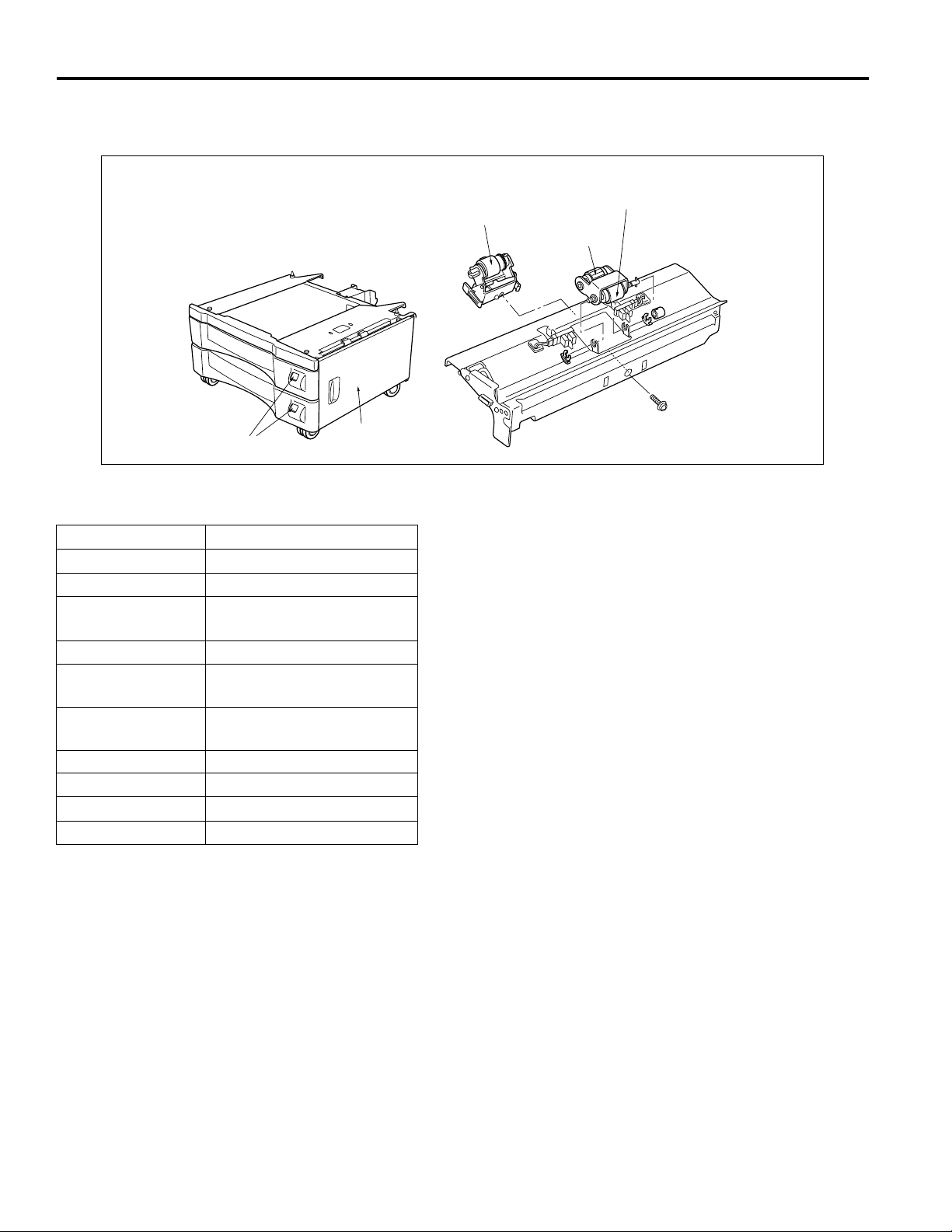
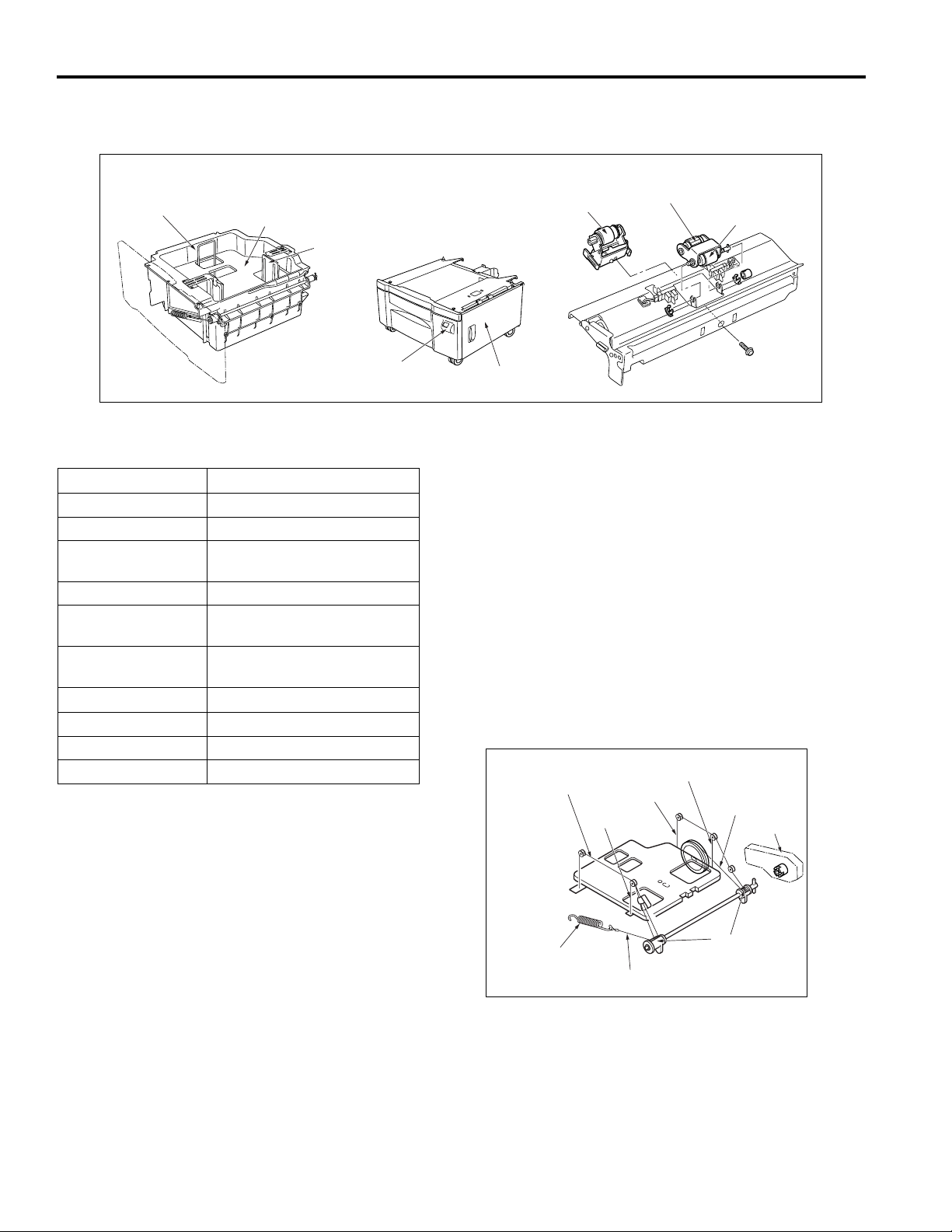
DISASSEMBLY/ASSEMBLY
Caution: Make sure the power plug is taken
out of the socket.
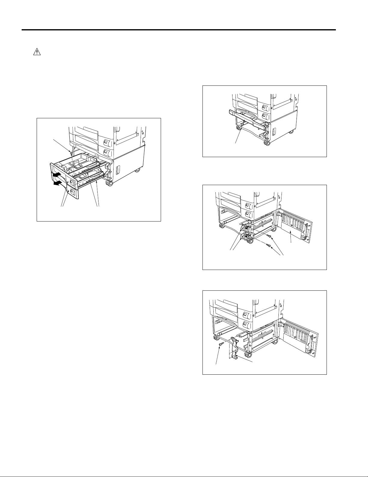
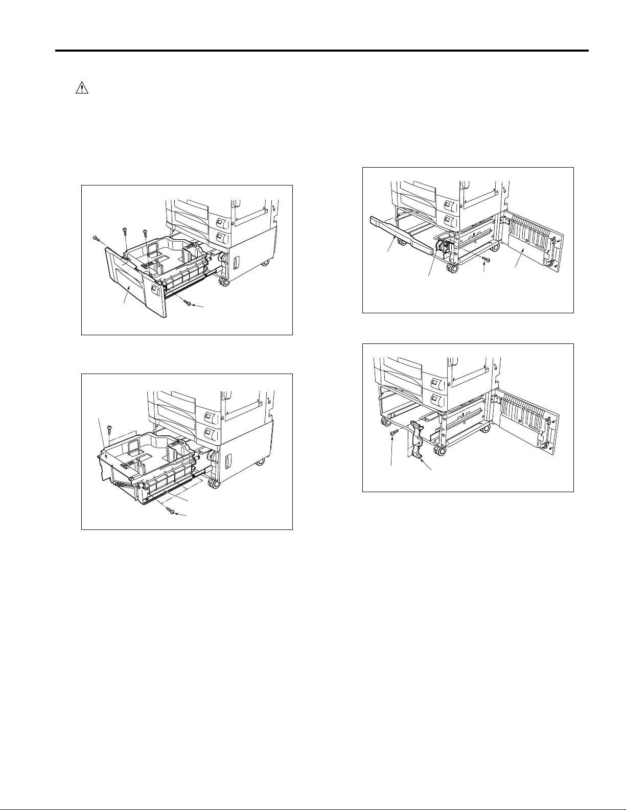
[1] Removing and reinstalling paper
feed tray
(1) Pull out the paper feed tray and take out the 2 set
screws on the right hand side.
(2) Remove the paper tray from the guide rails.
Set screws
Paper feed trays
Guide rails
[2] Removing and reinstalling the
paper feed unit
(1) Remove the tray cover and the paper tray.
Tray cover
(2) Opening the paper feed door, take out the 3 set
screws and remove the size setting unit.
(3) Install by reversing the removal procedure.
Paper feed door
Size setting unit
Set screws
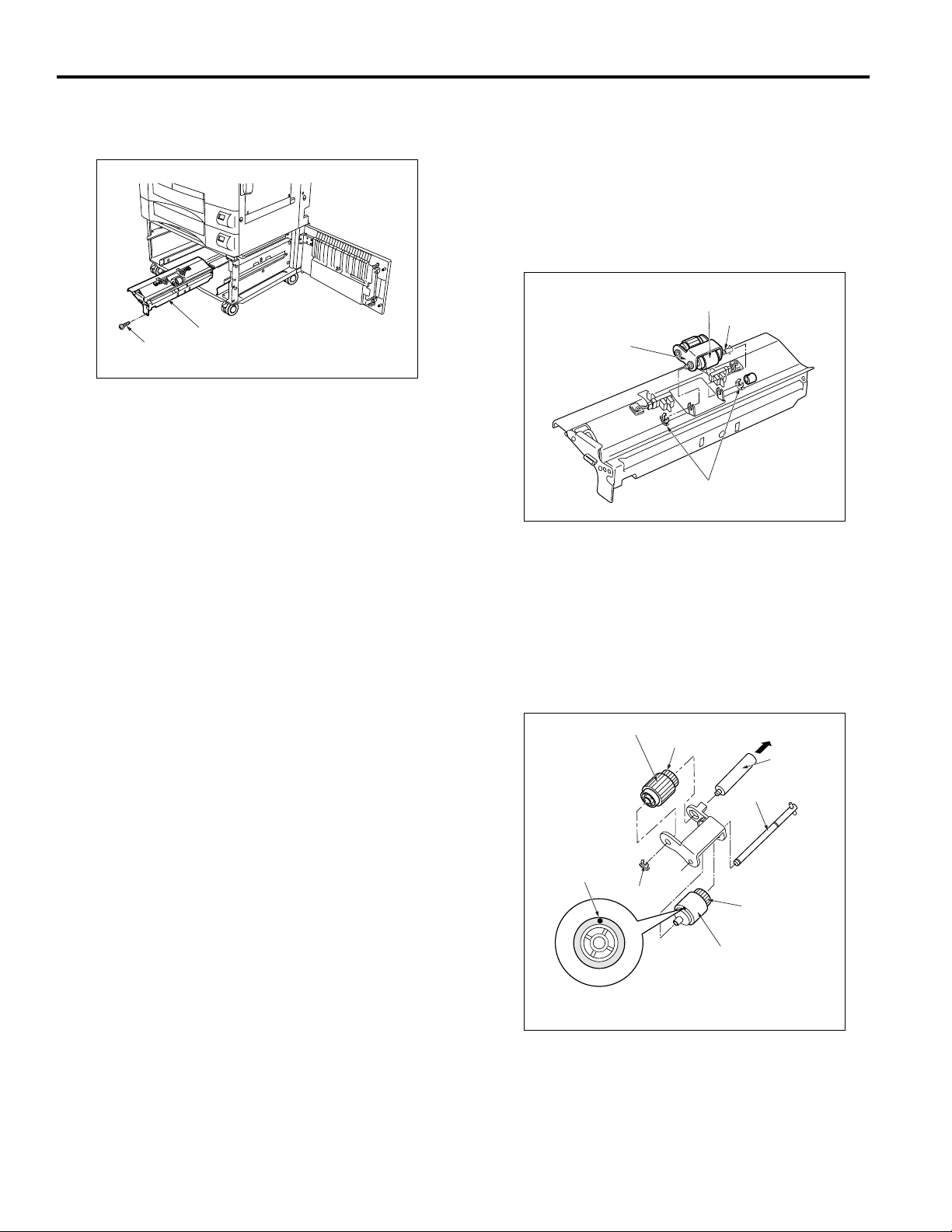
(3) Remove the 3 set screws and remove the cover.
Cover
Set screws
(4) Remove the paper feed unit connector.
10
Page 19
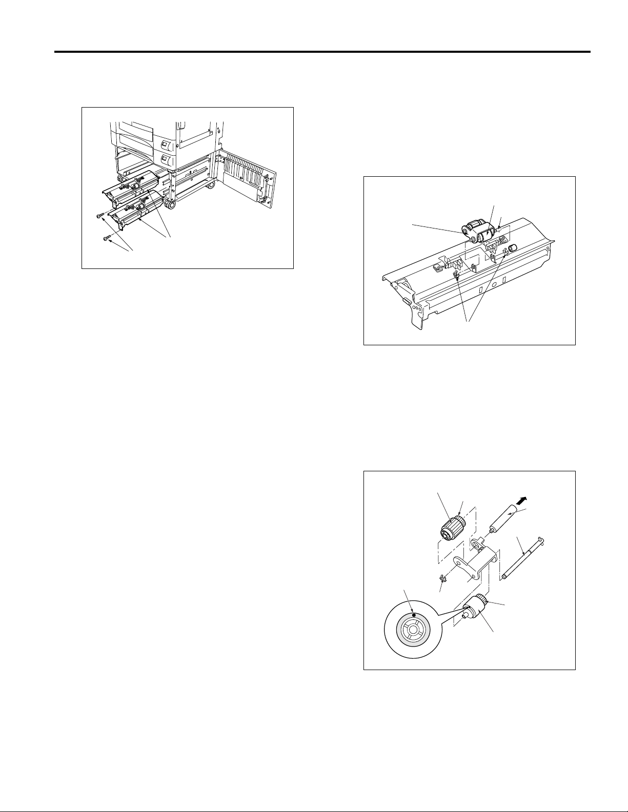
(5) Remove the 2 screws indicated by the engraved
arrows and remove by drawing the paper feed unit
forward.
Paper feed units
Set screws
(6) Install by reversing the removal procedure.
Caution: Immediately after installing the paper feed
unit, as the swing gear and the paper feed
solenoid are not in the correct position, it
sometimes happens that paper is not fed.
For this reason, always make a copy to
confirm that operation is normal.
DB-209/210/409/410
[3]
Replacing of the feed roller rubber and
double feed prevention rubber/upper
(1) Remove the paper feed unit.
(2) Remove the fixing rings and bearings.
(3) While withdrawing the paper feed shaft, remove the
double feed prevention roller/upper from the paper
feed roller unit.
Double feed prevention roller/upper
Paper feed roller unit
Stopper rings
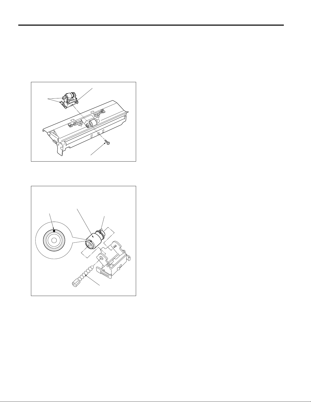
(4) Removing the fixing ring and remove the feed roller
by withdrawing the guide shaft in the direction
shown by the arrow.
(5) Remove the feed rubber from the feed roller.
(6) Remove the feed shaft and then remove the double
feed prevention roller/upper.
(7) Remove the double feed prevention rubber/upper
from the double feed prevention roller/upper.
Feed shaft
Feed rubber
Paint mark
Stopper ring
Feed roller
Guide shaft
Feed shaft
Double feed
prevention
roller/upper
Double feed
prevention
rubber/upper
(8) Install by reversing the removal procedure.
Caution:
Pay attention to the direction in which you install
each roller rubber. Install so that the swing-gear
shaft enters the paper feed roller unit.
11
Page 20
DB-209/210/409/410
[4] Replacing the double feed
prevention rubber/lower
(1) Remove the paper feed unit.
(2) Remove the set screw.
(3) Pushing the knobs on either side of the double feed
prevention unit, then remove by drawing it forward.
Double feed
Knobs
Set screw
prevention unit
(4) While pushing the projection of the lever click shaft,
withdraw it and remove the double feed prevention
roller.
Double feed prevention
Paint mark
rubber/lower
Double feed prevention
roller
Lever click shaft
(5) Remove the double feed prevention rubber/lower
from the double feed prevention roller.
(6) Install by reversing the removal procedure.
Caution : Pay attention to the direction in which
you install each roller rubber.
When installing the double-feed
prevention unit into the main body, be
sure to align it with the center of the
mark engraved on the main-body
plate.
12
Page 21

DB-409/410 PRODUCT SPECIFICATIONS
[1] Type
Type: Tray Paper Feed
(Front Loading)
[2] Functions
Paper size: A4, A4R, B5, B5R, 8.5 x 11,
8.5 x 11R
Paper type: 16 lb. - 24 lb. high quality
paper
Maximum
paper capacity: 1,500 Sheets
(22 lb.)
[3] Machine data
Power: DC24V/5V (supplied from
main body)
Power consumption: Max.40VA (When the PTC
heater is not in use.)
Weight: Approximately 52 lb.
Machine dimensions: Length 22.8 in.
Depth 23.4 in.
Height 12.2 in.
DB-209/210/409/410
[4] Maintenance
Maintenance: Same as main body
[5] Machine environment
Temperature: 50 to 86°F
Humidity: 20 to 80%RH
Note : Specifications are subject to change without
notice.
13
Page 22
DB-209/210/409/410
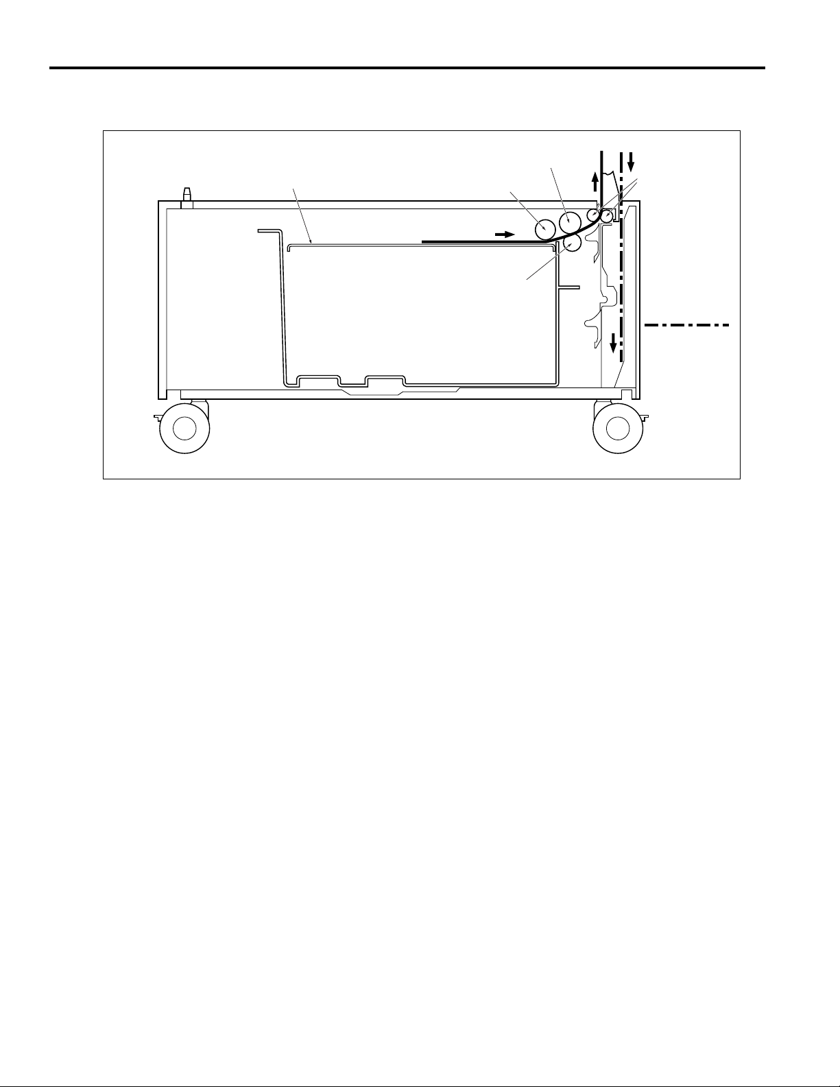
CENTER CROSS SECTION
Tray
Double feed prevention roller/upper
Feed roller
Double feed prevention
roller/lower
Conveyance
roller
Paper feed path
for the reverse
side copy
:
14
Page 23
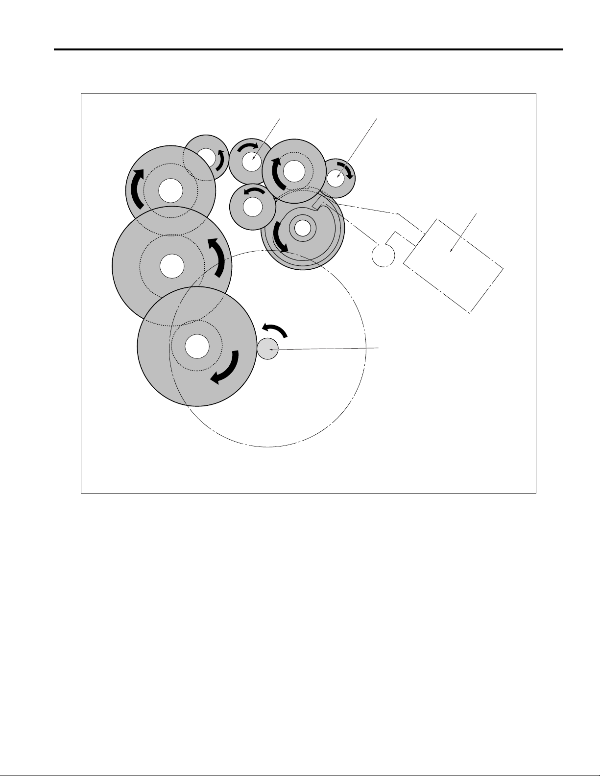
DRIVE SYSTEM DIAGRAM
DB-209/210/409/410
Conveyance roller
Double feed prevention roller/upper
1st Paper feed SD (SD101)
Paper feed motor (M100)
15
Page 24
DB-209/210/409/410
PAPER FEED SECTION
[1] Composition
Rear edge stopper
Paper lift-up plate
Side guide
Double feed prevention
roller/lower
Feed roller
Double feed
prevention
roller/upper
[2] Mechanisms
Mechanism Method
Paper feed Paper feed roller
Paper lift-up * Paper lift-up plate
Double feed Torque limiter
prevention
Tray loading Front loading
1st paper feed Paper feed SD
Feed roller
Jam processing Release of pressure on
double feed prevention roller
No paper detect Photosensor
Paper size detect Size setting unit
Paper conveyance Roller conveyance
Conveyance drive Gears
Size setting unit
Paper feed door
* Paper lift-up
The paper tray (LCT) is suspended on 4 up/down
drive wires (wires A, B, C, and D). When paper is
supplied to the paper tray, the tray falls under the
weight of the paper itself, but through the tension
of the drive assist spring, balance with the weight
of the paper is maintained.
When the paper tray (LCT) is loaded, the motor
rotates, causing the wire to be wound around the
drive pulley. As a result, the tray rises.
When the paper tray is withdrawn from the suspension base, the coupling with the drive is disconnected, and the tray falls to the position in
which the balance between the weight of the paper
and the drive-assist spring is maintained.
Wire A
Wire B
Wire D
Wire C
Detection
wire
Tray motor
(M101)
16
Drive assist
spring
Drive pulleys
Assist wire
Page 25
DB-209/210/409/410
DB
DB-409/410
Not connected
Undefined
Signal
DB-SELECT 1
L
H
L
DB-SELECT 0
H
H
L
[3] Paper feed and no paper detection
control
M100 CONT
SD101 CONT
DB SELECT1
DB SELECT0
MAIN BODY
24VDC
24VDC
PGND
PGND
5VDC
SGND
PS103
PS109
M100 CONT
M100 LD
M100 CLK
M100 CONT
SD101 DRIVE
PS103 SIG
PS109 SIG
LCTDB
24VDC
PGND
24VDC
24VDC
P.GND
5VDC
S.GND
24VDC
SGND
5VDC
SGND
5VDC
M100
EM
DB-409
M100
DB-410
SD101
PS103
PS109
2. Signals
a. Input signals
(1) PS103 (PS103 -> LCTDB)
Tray paper/no paper detection signal
[H]: no paper
[L] :with paper
(2) PS109 (PS109 -> LCTDB)
Paper level in tray detection signal
Turns on with [L], sends main body that little paper is left.
(3) SD101 CONT (MAIN BODY -> LCTDB)
SD101 ON/OFF control signal from main body
[H]: OFF
[L] :ON
b. Output signals
(1) M100 CONT (LCTDB -> M100)
M100 drive control signal
Paper feed is carried out by transmitting the drive of the M100
(DB paper feed motor) to the paper feed roller and to the
feed roller. When feed starts, SD101 (1st. paper feed SD)
raises and lowers the feed roller and contacts the paper.
Drive of the M100, SD101 is carried out by LCTDB (LCT
drive board) and controlled by the main body.
No paper detection is carried out with PS103 (No paper
detect PS) and controlled by the main body via the LCTDB.
A related signal is the PS109 (Paper level detect PS2)
which sent the remaining paper level to the main body.
1. Operation
a. Paper feed operation timing
(1) 1st. sheet start
A specified time after start button is turned ON
(2) 2nd. sheet start
A specified time after 1st. sheet SD101 is turned ON
(3) OFF timing
A specified time after SD101 is turned ON
[H]: M100 OFF
[L]: M100 ON
(2) M100 CLK (LCTDB -> M100)
M100 rotation control board clock signal
(3) SD101 (LCTDB -> SD101)
SD101 drive control signal
[H]: OFF
[L] :ON
(4) PS103 (LCTDB -> MAIN BODY)
Paper/no paper detection signal sent to main body
(5) DB SELECT (LCTDB -> MAIN BODY)
DB type identification signals that is sent to the main
body
b. No paper detection
If paper in the tray is used up, PS103 goes OFF and
no paper detection signal is sent to the main body via
the LCTDB.
17
Page 26
DB-209/210/409/410
[4] Tray up and down control
24VDC
24VDC
PGND
PGND
5VDC
SGND
M101 CONT
PS101
PS102
MAIN BODY LCTDB
1. Operation
When the paper feed tray of each level is set, PS101
(Tray detect PS) detects the tray, M101 (Tray motor)
turns ON and lifts the base plate in the tray. When the
tray is lifted, PS102 (Paper level detect PS1) detects
the paper upper limit and turns on, then M101 turns
off and the raising of the tray is completed.
The down operation of the trays is performed mechanically.
M101 DRIVE
24VDC
SGND
PS101
5VDC
SGND
PS102
5VDC
M101
PS101
PS102
2. Signals
a. Input signals
(1) PS101 (PS101 -> LCTDB)
Tray detect signal
By turning with [L] showing, M101 raises the paper in
the upper tray.
(2) PS102 (PS102 -> LCTDB)
Upper tray upper limit detection signal
When the upper tray paper is lifted and arrives at the
upper limit position, the signal becomes [H] and
M101 is turned off.
(3) M101 CONT (MAIN BODY -> LCTDB)
M101 ON/OFF control signal from main body
b. Output signals
(1) M101 DRIVE (LCTDB -> M101)
M101 drive control signal
[L]: M101 ON
[H]: M101 OFF
(2) PS101 (LCTDB -> MAIN BODY)
Tray detection signal sent to main body
(3) PS102 (LCTDB -> MAIN BODY)
Paper upper limit detect signal sent to main body
18
Page 27
DB-209/210/409/410
[5] Paper size detection control
SIZE SELECT
LCTDB
SIZE D
SIZE C
SIZE B
SIZE A
SW1
SDB
24VDC
24VDC
PGND
PGND
5VDC
SGND
SIZE D
SIZE C
SIZE B
SIZE A
MAIN BODY
Tray paper size is detected in the main body by a signal
sent from SDB (size detection board) via the LCTDB (LCT
drive board).
1. Operation
a. Tray paper size detection
Paper size for either tray is set by SW1 above SDB
and the LCTDB detects the switch signal corresponding to the position of SW1.
2. Signals
a. Input signal
(1) SIZE A - D (SDB -> LCTDB)
Tray paper size detect signal
b. Output signal
(1) SIZE A - D (LCTDB -> MAIN BODY)
Paper size detection signal sent to main body
The relation between switch signal and paper size is
as follows.
Paper size
Switch signal
(Label display
order)
SIZE A SIZE B SIZE C SIZE D
8.5 x 11R
A4
A4R
8.5 x 11
8.5 x 11R
B5R
B5
A4
A4R
8.5 x 11
19
Page 28
DB-209/210/409/410
[6] Control of paper-level detection
NAIN BODY
SGND
5VDC
LCTDB
SGND
PS101
5VDC
SGND
PS109
5VDC
PS101
PS109
After the trays have been set in the machine, paper level is
detected by PS101 (tray detect PS) and PS109 (paper
level detect PS2).
As the paper level in tray runs low, the actuator at the rear
part of the tray gradually rotates as illustrated below. The
remaining paper level is detected based on the ON/OFF
states of PS101 and PS109.
Direction of rotation when the
paper lifting plate is rising.
Viewing from the rear
Actuator
Paper level detect
sensor 2 (PS109)
Tray detect
sensor (PS101)
1. Operation
a. Detection of paper level in tray
The following shows the relation between the paper
level and the number of slit detections by the sensor
(PS101 or PS109).
Paper level PS101 PS109
Full
Medium
Low
20
Page 29
DISASSEMBLY/ASSEMBLY
DB-209/210/409/410
Caution: Make sure the power plug is taken
out of the socket.
[1] Removing and reinstalling the
paper feed tray
(1) Pull out the paper tray and take out the 4 set
screws and remove the tray front cover.
Set screws
Tray front cover
(2) Remove the 5 set screws from the guide rails and
remove paper tray from guide rails.
Set screws
[2] Removing and reinstalling the
paper feed unit
(1) Remove the tray cover and the paper tray.
(2) Open the paper feed door, remove the three set
screws, then remove the size setting unit.
Tray cover
Size setting
unit
(3) Remove the 3 set screws and remove the cover.
Set screws
Paper feed door
Paper tray
Set screws
Guide rail
Set screws
(3) Install by reversing the removal procedure.
Set screws
(4) Remove the paper feed unit connector.
Cover
21
Page 30
DB-209/210/409/410
(5) Remove the set screw indicated by the arrow
marking, and remove the paper-feed unit by pulling
it forward.
Set screw
Paper feed unit
(6) Install by reversing the removal procedure.
Caution 1: Immediately after installing the paper
feed unit, as the swing gear and the
paper feed solenoid are not in the correct
position, it sometimes happens that
paper is not fed. For this reason, always
make a copy to confirm that operation is
normal.
Caution 2: Install so that the swing gear shaft enters
the paper feed roller unit.
[3] Replacing the feed roller rubber and
double feed prevention rubber/upper
(1) Remove the paper feed unit.
(2) Remove the fixing rings and bearings.
(3) While withdrawing the paper feed shaft, remove the
double feed prevention roller/upper from the paper
feed roller unit.
Double feed prevention roller/upper
Feed shaft
Paper feed roller unit
Stopper rings
(4) Removing the fixing ring and remove the feed roller
by withdrawing the guide shaft in the direction
shown by the arrow.
(5) Remove the feed rubber form the feed roller.
(6) Remove the feed shaft and then remove the double
feed prevention roller/upper.
(7) Remove the double feed prevention rubber/upper
from the double feed prevention roller/upper.
Feed rubber
Paint mark
Fixing ring
Feed roller
Guide shaft
Feed shaft
Double feed
prevention
roller/upper
Double feed
prevention
rubber/upper
(8) Install by reversing the removal procedure.
Caution: Pay attention to the direction in which you install
each roller rubber. Install so that the swing-gear
shaft enters the paper feed roller unit.
22
Page 31

[4] Replacing the double feed
prevention rubber/lower
(1) Remove the paper feed unit.
(2) Remove the set screw.
(3) Pushing the knobs on either side of the double feed
prevention unit, then remove by drawing it forward.
DB-209/210/409/410
Knobs
Double feed prevention unit
Set screw
(4) While pushing the projection of the lever click shaft,
withdraw it and remove the double feed prevention
roller.
Paint mark
Double feed
prevention
rubber/lower
Double feed
prevention roller
Lever click shaft
(5) Remove the double feed prevention rubber/lower
from the double feed prevention roller.
(6) Install by reversing the removal procedure.
Caution: Pay attention to the direction in which you
install each roller rubber.
When installing the double-feed prevention
unit into the main body, align the unit with
the center of the marking stamped on the
main-body plate.
23
Page 32

DB-209/210/409/410
[5] Replacing the wires
Caution 1: After finishing wire replacement or
rewiring, raise and lower the tray by
hand to confirm that it rises and lowers
smoothly.
Caution 2: Do not cross wires or run them one on
top of another.
Caution 3: After installing wires, adjust the tray’s
tilt.
<Removing the wires>
Wire lengths
Wire A: 518.6±0.4mm
Wire B: 293.6±0.4mm
Wire C: 317.5±0.4mm
Wire D: 423.0±0.4mm
Assist wire: 245.2±0.5mm
Detection wire: 394.8±0.4mm
2. Remove assist wire from drive assist spring.
Tension fitting
2.
Drive assist spring
Set screw
E-ring
Assist wire
Wire A
Assist wire
Wire
protection
cover
Wire B
Drive pulley
(front)
1. 1.
4. 5.
Wire A
Wire B
Assist wire
Wire C
Drive pulley (rear)
3. Rotating the drive assist reel counter clockwise, remove
the detection wire from the reel.
Wire D
Wire C
Detection
wire
Wire
protection
cover
Set screw
Wire D
Detection wire
E-ring
3.
1. Remove front and rear wire
4. Detaching the E-ring, remove
5. Detaching the E-ring, slide the
6. Remove wire.
Drive assist reel
Detection wire
protection covers.
the drive pulley (front).
drive pulley (rear) forward.
24
Page 33

<Stringing wires>
DB-209/210/409/410
7. Attach the assist wire to the
drive assist spring. Turn the
tension fitting to apply
tension, and tighten the
screw.
7.
Drive assist spring
Tension fitting
Assist wire
Wire
protection
cover
1. Pass wires A, B, C, and D through tray.
2. Pass wires A and B along pulley groove
and pass over the adjustment material.
3. Pass wires C and D along pulley groove.
Wire A
2.
1.
Wire B
10.
Wire C
3.
11.
Wire D
8. Raise the paper lift plate. With the
wire tip pointing upward, wind
wires C and D around the drive
pulley 3 times. Then wind the
detection wire 1 time around to the
left (counterclockwise).
8.
9.
Wire
protection
cover
Drive assist reel
Detection
wire
9. Rotate the detection
wheel approximately 1 turn counterclockwise, so that
the detection wire
winds 1 time around
the reel (starting
from the top).
Set screw
5.
Drive pulley (front)
E-ring
Assist wire
2
5. Having inserted assist wire and wires A and B into
the drive spindle, push the drive pulley on and fasten
the E-ring.
6. Wind the assist wire 5 times around the drive pulley
in a rightward direction.
Assist wire
Wire B
5 times around in a
rightward direction
Set screw
4.
6.
Wire C
4. Having inserted detection wire and
wires C and D into the drive spindle,
push the drive pulley on and fasten with
the E-ring.
11.Install the (rear) wire protection cover.10.Install the (front) wire protection cover.
Wire DWire A
Detection wire
Drive pulley
(rear)
E-ring
2
25
Page 34

DB-209/210/409/410
Blank
26
Page 35

DB-209/210/409/410
DB-209/210 ELECTRICAL PARTS LAYOUT DRAWING
PS104 Jam detect PS1
PS102 Upper limit detect PS (upper)
PS103 No paper detect PS (upper)
PTC heater
SDB1 Size detection board 1
SDB1 Size detection board 2
PS107 Upper limit detect PS (lower)
SD101 1st paper feed SD (upper)
M100 Paper feed motor
PS108 No paper detect PS (lower)
PS105 Jam detect PS2
PS101 Tray detect PS (upper)
PS106 Tray detect PS (lower)
M101 Tray motor1
M102 Tray motor2
PFUDB PFU drive board
SD102 1st paper feed SD (lower)
27
Page 36

DB-209/210/409/410
DB-409/410 ELECTRICAL PARTS LAYOUT DRAWING
PS102 Paper level detect PS1
PTC Heater
SDB 1 Size detection board 1
SD101 1st paper feed SD
PS103 No paper detect PS
PS104 Jam detect PS1
PS105 Jam detect PS2
LCTDB LCT drive board
M101 Tray motor
M100 Paper feed motor
PS101 Tray detect PS
PS109 Paper level detect PS2
28
Page 37

DB-209/210 CONNECTOR LAYOUT DRAWING
DB-209/210/409/410
PFU drive board
CN102
(DB-209:6pin)
(DB-210:11pin)
CN100
(6pin)
CN103
(24pin)
CN101
(26pin)
CN104
(19pin)
J70 (W:6pin)
J69 (W:6pin)
CN1
(5pin)
Size detection board 2Size detection board 1
CN1
(5pin)
J68 (W:7pin)
CN113 (W:12pin)
J64 (W:8pin)
J66 (W:3pin)
J67 (W:3pin)
J63 (W:6pin)
J65 (W:11pin)
29
Page 38

DB-209/210/409/410
DB-409/410 CONNECTOR LAYOUT DRAWING
CN102
(DB-409:6pin)
(DB-410:11pin)
LCT drive board
CN100
(6pin)
CN103
(24pin)
CN101
(26pin)
CN105
(DB-410:3pin)
Size detection board 1
CN1
(5pin)
CN105
(DB-409:3pin)
J69 (W:6pin)
CN113 (W:2pin)
J64 (W:8pin)
J66 (W:3pin)
J68 (W:3pin)
J63 (W:6pin)
30
Page 39

DB-209/210/409/410
01234567 910118
3000ms
3000ms
1543ms75ms
293ms
243ms125ms
182ms
1543ms75ms
293ms
243ms125ms
182ms
1543ms75ms
293ms
243ms125ms
182ms
Symbol
Item
Time
(
sec
)
Registration clutchMC1
Loop clutchMC2
1st paper feed SD (upper)SD101
Registration PSPS1
V-Valid
Fixing exit PSPS2
Copy ON
Exit PS
DB Paper feed motor
PS3
M100
DB-209/DB409 TIME CHART (8.5X11, LIFE SIZE, 3 COPIES,
FEED FROM TRAY 3)
31
Page 40

DB-209/210/409/410
Blank
32
Page 41

DB-209/210/DB-409/410 OVERALL WIRING DIAGRAM
33
[How to see the diagram]
1.The signals shown reflect levels present
under normal idling conditions with
the main switch turned ON.
2.Wiring symbols in the figure are as follows.
(1) [Symbol]
Crimp
(2)
Signal types are as follows:
H
L
P
(3) RC is the flat cable.
(4) Signal flow
The solid black circle ( ) among
the connector symbols ( )
indicates the direction of signal flow.
Example)
CB
50-1
Connector
Relay connector
High level
Low level
Analog signal
Pulse signal
Direction of
signal flow
5VDC
PS1
SGND
Faston
PS1
Page 42

Blank
34
Page 43

PARTS CATALOG
Model
DB-209/DB-409
MARCH 2001
SECOND EDITION
KONICA BUSINESS TECHNOLOGIES, INC.
Page 44

Page 45

How to use this catalog
This parts catalog includes illustrations and part numbers for all replacement parts and assemblies used in this model.
Model-specific parts are identified in the illustrations with reference
numbers. Use the reference number to locate the corresponding part
number on the facing page.
Common hardware items, such as screws, nuts, washers, and pins,
are identified in the illustrations with reference letters. Use the reference
letter to locate the corresponding part number on the hardware listing in
the lower right hand corner of the facing page.
If you know a part number, but don’t know where the part is used, use
the numerical index to determine the page number and reference number for that part. Because some common parts are used in several
places, there may be more than one entry. Refer to the illustrations to
see where the part may be used.
If you know a part’s description, but don’t know where to look to find
the part number, use the alphabetical index to determine likely page and
reference numbers. Then look at the illustrations to determine that you
have identified the correct part. Locate the part number using the listing
on the opposite page.
Retail pricing that appears with the numerical index, while valid when
this catalog was printed, is subject to change without notice. The prices
are only suggested prices and are provided only for reference. Dealers
may determine their own selling prices. For up-to-date pricing, refer to
current Konica price lists or contact the Konica Parts Distribution Center.
How to order parts
Use standard Konica parts ordering procedures to obtain these parts.
For ordering options, contact Konica’s Parts Distribution Center.
When ordering parts, be sure to specify part numbers exactly as listed in
this catalog.
NOTE: Electrical parts may include previously used components.
Model DB-209/409 Konica Business Technologies, Inc. Page iii
2nd Edition March, 2001
Page 46

This page left blank intentionally.
Page iv Konica Business Technologies, Inc. Model DB-209/409
March, 2001 2nd Edition
Page 47

How to use this catalog . . . . . . . . . . . . . . . . . . . . . . . . . iii
Contents . . . . . . . . . . . . . . . . . . . . . . . . . . . . 1
DB-209 . . . . . . . . . . . . . . . . . . . . . . . . . . . . 2
Wiring . . . . . . . . . . . . . . . . . . . . . . . . . . . . 12
DB-409 . . . . . . . . . . . . . . . . . . . . . . . . . . . . 14
Wiring . . . . . . . . . . . . . . . . . . . . . . . . . . . . 24
Alphabetical index . . . . . . . . . . . . . . . . . . . . . . . . . . . 27
Numerical index, Retail price list . . . . . . . . . . . . . . . . . . . . 29
Contents
Model DB-209/409 Konica Business Technologies, Inc. Page 1
2nd Edition March, 2001
Page 48

DB-209
Page 2 Konica Business Technologies., Inc. Model DB-209/409
March, 2001 2nd Edition
Page 49

REF. PART NUMBER DESCRIPTION
NO.
1 26NA47350 Cassette stopper
2 13HA-1121 Inner heater assembly
3 13GU12050 Cassette detecting cover
4 12XQ10040 Main support roller/A
5 552085510 Photosensor
6 13HA40060 Actuator/Upper
7 13HA40070 Driven spring
8 13GU40110 Shaft holder part
9 13HA90030 LCT wiring/2
10 13HA40020 Paper feed connecting roller/3
11 26NA40820 Paper feed slide shaft holder
12 26NA40270 Side guide plate
13 13HA10420 Lock part
14 13HA40150 Paper feed driven shaft holder
15 26NA40890 Slide bearing
16 26NA40680 Paper feed driven roller/Lower
17 13HA10530 Guide sheet/2
18 13HA10370 Main positioning shaft
19 13HA-1090 Main support plate left assembly
20 13HA-1070 Main support plate right assembly
HARDWARE
REF.
LTR.
a 00Z283061
b 00Z193061
c 00Z183061
d 00Z283081
e 00Z193041
g 00Z194101
h 00Z253081
j 00Z183121
k 00Z924316
m 00Z670206
n 00Z670606
p 00Z921941
PART
NUMBER
Model DB-209/409 Konica Business Technologies., Inc. Page 3
2nd Edition March, 2001
Page 50

DB-209
Page 4 Konica Business Technologies., Inc. Model DB-209/409
March, 2001 2nd Edition
Page 51

REF. PART NUMBER DESCRIPTION
NO.
1 13HA12060 Side cover/Left
2 13GU12040 Front fixed cover
3 26NA53931 Fixed screw
4 13HA12150 Cord cover
5 13HA12080 Side cover/Right
6 13HA12020 Door/Right
7 13HA10470 Door fulcrum part
8 13HA10460 Door fulcrum plate
9 13HA40080 Guide plate/Middle
10 26NA50091 Open-close knob
11 26NA50080 Lock claw
12 13HA12160 Lock spring/Upper
13 13HA12170 Lock spring/Lower
14 26NA50630 Shaft holder part/Upper
15 26NA50640 Shaft holder part/Lower
16 466078010 Pin A
17 13HA10340 Hinge plate/A
18 13HA-1260 Guide plate/B assembly
19 * Not used
20 26NA10061 Cassette rail/Right
21 13HA10170 Actuator/Lower
22 13HA12070 Rear cover
23 13HA10550 Spacer/A
24 26NA12540 Accessories holding panel
HARDWARE
REF.
LTR.
a 00Z283081
b 00Z193061
c 00Z283061
d 00Z193062
e 00Z253081
f 00Z670256
g 00Z254081
h 00Z670306
j 00Z193081
PART
NUMBER
Model DB-209/409 Konica Business Technologies., Inc. Page 5
2nd Edition March, 2001
Page 52

DB-209
Page 6 Konica Business Technologies., Inc. Model DB-209/409
March, 2001 2nd Edition
Page 53

REF. PART NUMBER DESCRIPTION
NO.
1 13HA40040 Wiring guide part
2 13HA-4040 Paper feed shaft/Rear assembly
3 26NA40280 Paper detecting actuator
4 26NA40750 Paper detecting actuator/2
5 552085510 Photosensor
6 26NA40700 Shaft positioning part
7 540076010 Paper feed shaft holder
8 13HA40030 Paper feed mount plate
9 26NA40090 Paper feeding rubber
10 26NA40080 Feeding roller
11 26NA16310 Paper feed gear (Z=15)
12 13GU40110 Shaft holder part
13 40AA40150 Shaft positioning part
14 40AA76040 Feeding shaft holder
15 26NA40510 Paper feed idler gear (Z=17)
16 26NA40110 Double feed preventive rubber/Upper
17 26NA40100 Double feed preventive roller/Upper
18 * Not used
19 * Not used
20 26NA40120 Double feed preventive rubber/Lower
21 26NA40500 Double feed preventive roller
22 40AA40181 Lever click shaft
23 13HA10450 Paper feed rotary spring
24 40AA40450 Double feed pressure spring
25 13GU40100 Shaft holder mount plate
26 13HA-1131 Guide plate/Middle assembly
27 13HA40180 Holder part
28 13HA10560 Guide sheet/3
HARDWARE
REF.
LTR.
PART
NUMBER
a 00Z193061
b 00Z253081
c 00Z194061
d 00Z670306
e 00Z193051
f 00Z183121
g 00Z670406
h 00Z712106
i 00Z610501
j 00Z600506
Model DB-209/409 Konica Business Technologies., Inc. Page 7
2nd Edition March, 2001
Page 54

DB-209
Page 8 Konica Business Technologies., Inc. Model DB-209/409
March, 2001 2nd Edition
Page 55

REF. PART NUMBER DESCRIPTION
NO.
1 13HA10250 LCT sensor cover
2 13HA-1540 Solenoid mount plate assembly
3 26NA82510 Paper feed solenoid
4 26NA40830 Positioning arm
5 26NA40760 Lever hold spring
6 13HA10431 Wiring guide part/B
7 13HA40020 Paper feed connecting roller/3
8 26NA40820 Paper feed slide shaft holder
9 13HA77060 Driving gear (Z=15)
10 26NA-4780 Cassette lock assembly
11 25BA47461 Cassette positioning catch/U
12 26NA80041 Cassette driving motor
13 13HA77050 Idler gear/D (Z=17)
14 13HA77020 Idler gear/A (Z=19/44)
15 13HA77030 Idler gear/B (Z=19/40)
16 13HA77040 Idler gear/C (Z=16/31)
17 26NA-1680 Paper gear/2 assembly
18 13HA77080 Idler gear/F (Z=16)
19 13HA15110 Spacer
20 * Not used
21 * Not used
22 13HA77090 Paper feed coupling gear/A
23 13GU-9010 PFU driving board assembly
24 13HA77010 Motor gear (Z=18)
25 13HA15020 Driving panel/2
26 12RQ80010 Paper feed driving motor
27 26NA47390 Cassette fixed spring
28 13GU-1500 Driving assembly
29 26NA17490 Paper feed coupling gear/B
HARDWARE
REF.
LTR.
a 00Z193061
b 00Z283061
c 00Z670406
d 00Z670306
e 00Z163051
i 00Z193201
j 00Z184081
m 00Z670606
n 00Z925106
q 00Z183043
PART
NUMBER
Model DB-209/409 Konica Business Technologies., Inc. Page 9
2nd Edition March, 2001
Page 56

DB-209
Page 10 Konica Business Technologies., Inc. Model DB-209/409
March, 2001 2nd Edition
Page 57

REF. PART NUMBER DESCRIPTION
NO.
1 * Not used
2 26NA47040 Paper feed regulating plate/Left
3 26NA-4740 Lift-up bottom plate assembly
4 26NA47023 Cassette base/Lower
5 * Not used
6 40AA47130 Adjusting plate
7 40AA77290 Pinion (Z=16)
8 * Not used
9 * Not used
10 * Not used
11 *
12 * Not used
13 * Not used
14 26NA47390 Cassette fixed spring
15 25BA47461 Cassette positioning catch/U
16 26NA47291 Cassette remained detecting actuator
17 26NA47300 Ground plate
18 26NA47060 Paper lift-up plate
19 26NA97300 Cassette click label
20 26NA47260 Paper feed indicating plate/Front
21 26NA47240 Cassette detecting connector
22 26NA47250 Cassette detecting base
23 26NA-9200 Size detecting board assembly
24 26NA47280 Spring lock plate
25 26NE97290 Cassette indication label/Lower
26 26NA-4760 Lift-up shaft assembly
27 26NA47380 Fixing seal
28 26NA-4721 Side regulating plate/Front assembly
29 26NA-4730 Side regulating plate/Rear assembly
HARDWARE
REF.
LTR.
PART
NUMBER
a 00Z670406
b 00Z670606
d 00Z254081
e 00Z254121
f 00Z610301
g 00Z283061
h 00Z253081
j 00Z463103
k 00Z620301
Model DB-209/409 Konica Business Technologies., Inc. Page 11
2nd Edition March, 2001
Page 58

Wiring
Page 12 Konica Business Technologies., Inc. Model DB-209/409
March, 2001 2nd Edition
Page 59

REF. PART NUMBER DESCRIPTION
NO.
1 13GU90010 PFU wiring/1
2 13GU90020 PFU wiring/2
3 13HA90010 LCT electrify wiring
4 26NA90330 Sensor relay wiring/3
5 13HA90030 LCT wiring/2
6 13HA90040 LCT wiring/3
7 13HA90060 LCT wiring/5
8 13HA90020 LCT wiring/1
Model DB-209/409 Konica Business Technologies., Inc. Page 13
2nd Edition March, 2001
Page 60

DB-409
Page 14 Konica Business Technologies., Inc. Model DB-209/409
March, 2001 2nd Edition
Page 61

REF. PART NUMBER DESCRIPTION
NO.
1 13HA-1121 Inner heater assembly
2 13HA-9720 Cassette label assembly
3 26NA47260 Paper feed indicating plate/Front
4 26NA47240 Cassette detecting connector
5 26NA-9200 Size detecting board assembly
6 26NA47250 Cassette detecting base
7 26NA47280 Spring lock plate
8 12XQ10040 Main support roller/A
9 13GU40110 Shaft holder part
10 552085510 Photosensor
11 13HA40060 Actuator/Upper
12 13HA90030 LCT wiring/2
13 13HA10390 Sensor cover
14 13HA40020 Paper feed connecting roller/3
15 26NA40820 Paper feed slide shaft holder
16 26NA40270 Side guide plate
17 13HA40070 Roller spring
18 13HA40150 Paper feed driven shaft holder
19 26NA40890 Slide bearing
20 26NA40680 Paper feed driven roller
21 13HA10420 Lock part/2
22 13HA12180 Cassette detecting cover
23 13HA10530 Guide sheet/2
24 * Not used
25 55TE97110 High temperature caution label
26 13HA10540 Protection sheet
27 13HA10370 Main positioning shaft
28 13HA-1090 Main support plate left assembly
29 13HA-1070 Main support plate right assembly
HARDWARE
REF.
LTR.
a 00Z283061
b 00Z193061
c 00Z183061
d 00Z283081
e 00Z924316
f 00Z253081
g 00Z194101
h 00Z183121
j 00Z670206
k 00Z670606
m 00Z193041
n 00Z921941
PART
NUMBER
Model DB-209/409 Konica Business Technologies., Inc. Page 15
2nd Edition March, 2001
Page 62

DB-409
Page 16 Konica Business Technologies., Inc. Model DB-209/409
March, 2001 2nd Edition
Page 63

REF. PART NUMBER DESCRIPTION
NO.
1 13HA12060 Fixed cover/Left
2 13HA12190 Front fixed cover
3 13HA12010 Front cover
4 26NA53931 Fixed screw
5 13HA12150 Cord cover
6 13HA12080 Side cover/Right
7 13HA12020 Door/Right
8 13HA10470 Door fulcrum part
9 13HA10460 Door fulcrum plate
10 13HA40080 Guide plate/Middle
11 26NA50080 Lock claw
12 13HA12160 Lock spring/Upper
13 13HA12170 Lock spring/Lower
14 26NA50630 Shaft holder part/Upper
15 26NA50640 Shaft holder part/Lower
16 466078010 Pin A
17 26NA50091 Open-close knob
18 13HA10340 Hinge plate/A
19 13HA-1260 Guide plate/B assembly
20 * Not used
21 13HA12070 Rear cover
22 13HA10170 Actuator/Lower
23 13HA10550 Spacer/A
24 26NA12540 Accessories holding panel
HARDWARE
REF.
LTR.
a 00Z283081
b 00Z193061
c 00Z283061
d 00Z193062
e 00Z670256
f 00Z670306
g 00Z254081
h 00Z253081
j 00Z163101
PART
NUMBER
Model DB-209/409 Konica Business Technologies., Inc. Page 17
2nd Edition March, 2001
Page 64

DB-409
Page 18 Konica Business Technologies., Inc. Model DB-209/409
March, 2001 2nd Edition
Page 65

REF. PART NUMBER DESCRIPTION
NO.
1 13HA40040 Wiring guide part
2 13HA-4040 Paper feed driving shaft/Rear
3 13HA40171 Paper detecting actuator/Front
4 13HA40160 Paper detecting actuator/Rear
5 552085510 Photosensor
6 26NA40700 Shaft positioning part
7 540076010 Paper feed shaft holder
8 13HA40030 Paper feed mount plate
9 26NA40090 Paper feeding rubber
10 26NA40080 Feeding roller
11 26NA16310 Paper feed gear (Z=15)
12 13GU40110 Shaft holder part
13 40AA40150 Shaft positioning part
14 40AA76040 Feeding shaft holder
15 26NA40510 Paper feed idler gear (Z=17)
16 26NA40110 Double feed preventive rubber/Upper
17 26NA40100 Double feed preventive roller/Upper
18 13HA-1131 Guide plate/Middle assembly
19 * Not used
20 26NA40120 Double feed preventive roller/Lower
21 26NA40500 Double feed preventive roller
22 40AA40181 Lever click shaft
23 13HA10450 Paper feed rotary spring
24 40AA40450 Double feed pressure spring
25 13HA-4000 Paper feed assembly
26 13HA40180 Holder part
27 13HA10560 Guide sheet/3
HARDWARE
REF.
LTR.
a 00Z193061
b 00Z253081
c 00Z194061
d 00Z670306
e 00Z193051
f 00Z183121
g 00Z670406
h 00Z712106
i 00Z610501
j 00Z600506
PART
NUMBER
Model DB-209/409 Konica Business Technologies., Inc. Page 19
2nd Edition March, 2001
Page 66

DB-409
Page 20 Konica Business Technologies., Inc. Model DB-209/409
March, 2001 2nd Edition
Page 67

REF. PART NUMBER DESCRIPTION
NO.
1 13HA10250 LCT sensor cover
2 13HA-1540 Solenoid mount plate assembly
3 26NA82510 Paper feed solenoid
4 26NA40830 Positioning arm
5 26NA40760 Lever hold spring
6 12RQ80010 Paper feed driving motor
7 13HA40020 Paper feed connecting roller/3
8 26NA40820 Paper feed slide shaft holder
9 13HA77060 Driving gear (Z=15)
10 13HA-4780 LCT lock plate assembly
11 25BA47461 Cassette positioning cam/U
12 13HA80020 LCT driving motor
13 13HA77050 Idler gear/D (Z=17)
14 13HA77020 Idler gear/A (Z=19/44)
15 13HA77030 Idler gear/B (Z=19/40)
16 13HA77040 Idler gear/C (Z=16/31)
17 26NA-1680 Paper gear/2 assembly
18 13HA77080 Idler gear/F (Z=16)
19 13HA15110 Spacer
20 * Not used
21 * Not used
22 13HA77090 Paper feed coupling gear/A
23 13HA-9010 LCT driving board assembly
24 13HA77010 Motor gear (Z=18)
25 13HA15020 Driving panel/2
26 26NA47390 Cassette fixed spring
27 13HA-1500 Driving assembly
28 26NA17490 Paper feed coupling gear/B
HARDWARE
REF.
LTR.
a 00Z193061
b 00Z283061
c 00Z670406
d 00Z670306
e 00Z163051
i 00Z193301
j 00Z184081
m 00Z670606
n 00Z925106
q 00Z183043
PART
NUMBER
Model DB-209/409 Konica Business Technologies., Inc. Page 21
2nd Edition March, 2001
Page 68

DB-409
Page 22 Konica Business Technologies., Inc. Model DB-209/409
March, 2001 2nd Edition
Page 69

REF. PART NUMBER DESCRIPTION
NO.
1 13HA47270 Fixed plate
2 13HA47250 Reinforcing plate
3 540047200 Paper regulating claw
4 13HA47280 Paper guide plate
5 12RQ47030 Paper adjusting plate
6 13HA47170 Main mount plate/Right
7 12RQ47020 Paper guide plate
8 13HA10130 Rail mount plate/Right
9 13HA10431 Wiring guide part/B
10 13HA12130 External mount plate/3
11 13HA10140 Rail mount plate/Left
12 13HA10161 LCT slide rail
13 13HA47140 Driving auxiliary spring/A
14 564047230 Spring mount plate
15 13HA47150 Driving auxiliary spring/B
16 12RQ47160 Auxiliary wire
17 12RQ47090 Wire driving pulley/Front
18 12RQ47110 Pulley fixed part/Front
19 12RQ47230 Wire adjusting part
20 13HA47100 Lift-up wire/1
21 13HA47210 Wire pulley
22 13HA47110 Lift-up wire/2
23 13HA47220 Lift-up wire/4
24 13HA47120 Lift-up wire/3
25 13HA47190 Detecting spring
26 13HA47130 Detecting wire
27 13HA47090 Detecting plate
28 13HA47260 Pulley fixed part/Rear
29 13HA47370 Driving pulley
30 13HA47330 Slide sheet
31 13HA-4790 Fulcrum shaft assembly
32 13HA47340 Paper guide sheet/1
33 * Not used
34 13HA97050 LCT guide label
35 13HA47380 Adjusting cam
HARDWARE
REF.
LTR.
a 00Z193061
b 00Z193051
c 00Z283061
e 00Z254081
f 00Z183201
g 00Z163081
i 00Z670406
j 00Z193041
k 00Z610321
m 00Z510301
n 00Z610421
p 00Z510401
PART
NUMBER
Model DB-209/409 Konica Business Technologies., Inc. Page 23
2nd Edition March, 2001
Page 70

Wiring
Page 24 Konica Business Technologies., Inc. Model DB-209/409
March, 2001 2nd Edition
Page 71

REF. PART NUMBER DESCRIPTION
NO.
1 13HA90010 LCT electrify wiring
2 13HA90020 LCT wiring/1
3 13HA90040 LCT wiring/3
4 13HA90030 LCT wiring/2
5 13HA90050 LCT wiring/4
6 13HA90060 LCT wiring/5
7 26NA90330 Sensor relay wiring/3
Model DB-209/409 Konica Business Technologies., Inc. Page 25
2nd Edition March, 2001
Page 72

This page left blank intentionally.
Page 26 Konica Business Technologies, Inc. Model DB-209/409
March, 2001 2nd Edition
Page 73

Alphabetical index
PART PAGE REF.
DESCRIPTION NO. NO.
A
Accessories holding panel . 5 24
Accessories holding panel . 17 24
Actuator/Lower . . . . . . . 5 21
Actuator/Lower . . . . . . . 17 22
Actuator/Upper . . . . . . . 3 6
Actuator/Upper . . . . . . . 15 11
Adjusting cam . . . . . . . 23 35
Adjusting plate . . . . . . . 11 6
Auxiliary wire . . . . . . . . 23 16
C
Cassette base/Lower . . . . 11 4
Cassette click label . . . . . 11 19
Cassette detecting base . . 11 22
Cassette detecting base . . 15 6
Cassette detecting connector 11 21
Cassette detecting connector 15 4
Cassette detecting cover . . 3 3
Cassette detecting cover . . 15 22
Cassette driving motor . . . 9 12
Cassette fixed spring . . . . 9 27
Cassette fixed spring . . . . 11 14
Cassette fixed spring . . . . 21 26
Cassette indication
label/Lower . . . . . . 11 25
Cassette label assembly . . 15 2
Cassette lock assembly . . 9 10
Cassette positioning cam/U 21 11
Cassette positioning catch/U 9 11
Cassette positioning catch/U 11 15
Cassette rail/Right . . . . . 5 20
Cassette remained detecting
actuator . . . . . . . . 11 16
Cassette stopper . . . . . . 3 1
Cord cover . . . . . . . . . 5 4
Cord cover . . . . . . . . . 17 5
D
Detecting plate . . . . . . . 23 27
Detecting spring . . . . . . 23 25
Detecting wire . . . . . . . 23 26
Door fulcrum part . . . . . 5 7
Door fulcrum part . . . . . 17 8
Door fulcrum plate . . . . . 5 8
Door fulcrum plate . . . . . 17 9
Door/Right . . . . . . . . . 5 6
Door/Right . . . . . . . . . 17 7
Double feed pressure spring 7 24
Double feed pressure spring 19 24
Double feed preventive roller 7 21
Double feed preventive roller 19 21
Double feed preventive
roller/Upper . . . . . . 7 17
Double feed preventive
roller/Upper . . . . . . 19 17
Double feed preventive
roller/Lower . . . . . . 19 20
PART PAGE REF.
DESCRIPTION NO. NO.
Double feed preventive
rubber/Upper . . . . . . 7 16
Double feed preventive
rubber/Lower . . . . . . 7 20
Double feed preventive
rubber/Upper . . . . . . 19 16
Driven spring . . . . . . . . 3 7
Driving assembly . . . . . . 9 28
Driving assembly . . . . . . 21 27
Driving auxiliary spring/A . . 23 13
Driving auxiliary spring/B . . 23 15
Driving gear (Z=15) . . . . . 9 9
Driving gear (Z=15) . . . . . 21 9
Driving panel/2 . . . . . . . 9 25
Driving panel/2 . . . . . . . 21 25
Driving pulley . . . . . . . . 23 29
E
External mount plate/3 . . . 23 10
F
Feeding roller . . . . . . . . 7 10
Feeding roller . . . . . . . . 19 10
Feeding shaft holder . . . . 7 14
Feeding shaft holder . . . . 19 14
Fixed cover/Left . . . . . . 17 1
Fixed plate . . . . . . . . . 23 1
Fixed screw . . . . . . . . . 5 3
Fixed screw . . . . . . . . . 17 4
Fixing seal . . . . . . . . . 11 27
Front cover . . . . . . . . . 17 3
Front fixed cover . . . . . . 5 2
Front fixed cover . . . . . . 17 2
Fulcrum shaft assembly . . 23 31
G
Ground plate . . . . . . . . 11 17
Guide plate/B assembly . . 5 18
Guide plate/B assembly . . 17 19
Guide plate/Middle . . . . . 5 9
Guide plate/Middle . . . . . 17 10
Guide plate/Middle assembly 7 26
Guide plate/Middle assembly 19 18
Guide sheet/2 . . . . . . . 3 17
Guide sheet/2 . . . . . . . 15 23
Guide sheet/3 . . . . . . . 7 28
Guide sheet/3 . . . . . . . 19 27
H
High temperature caution
label . . . . . . . . . . 15 25
Hinge plate/A . . . . . . . . 5 17
Hinge plate/A . . . . . . . . 17 18
Holder part . . . . . . . . . 7 27
Holder part . . . . . . . . . 19 26
PART PAGE REF.
DESCRIPTION NO. NO.
I
Idler gear/A (Z=19/44) . . . 9 14
Idler gear/A (Z=19/44) . . . 21 14
Idler gear/B (Z=19/40) . . . 9 15
Idler gear/B (Z=19/40) . . . 21 15
Idler gear/C (Z=16/31) . . . 9 16
Idler gear/C (Z=16/31) . . . 21 16
Idler gear/D (Z=17) . . . . . 9 13
Idler gear/D (Z=17) . . . . . 21 13
Idler gear/F (Z=16) . . . . . 9 18
Idler gear/F (Z=16) . . . . . 21 18
Inner heater assembly . . . 3 2
Inner heater assembly . . . 15 1
L
LCT driving board assembly 21 23
LCT driving motor . . . . . . 21 12
LCT electrify wiring . . . . . 13 3
LCT electrify wiring . . . . . 25 1
LCT guide label . . . . . . . 23 34
LCT lock plate assembly . . 21 10
LCT sensor cover . . . . . . 9 1
LCT sensor cover . . . . . . 21 1
LCT slide rail . . . . . . . . 23 12
LCT wiring/1 . . . . . . . . 13 8
LCT wiring/1 . . . . . . . . 25 2
LCT wiring/2 . . . . . . . . 3 9
LCT wiring/2 . . . . . . . . 13 5
LCT wiring/2 . . . . . . . . 15 12
LCT wiring/2 . . . . . . . . 25 4
LCT wiring/3 . . . . . . . . 13 6
LCT wiring/3 . . . . . . . . 25 3
LCT wiring/4 . . . . . . . . 25 5
LCT wiring/5 . . . . . . . . 13 7
LCT wiring/5 . . . . . . . . 25 6
Lever click shaft . . . . . . . 7 22
Lever click shaft . . . . . . . 19 22
Lever hold spring . . . . . . 9 5
Lever hold spring . . . . . . 21 5
Lift-up bottom plate assembly 11 3
Lift-up shaft assembly . . . 11 26
Lift-up wire/1 . . . . . . . . 23 20
Lift-up wire/2 . . . . . . . . 23 22
Lift-up wire/3 . . . . . . . . 23 24
Lift-up wire/4 . . . . . . . . 23 23
Lock claw . . . . . . . . . . 5 11
Lock claw . . . . . . . . . . 17 11
Lock part . . . . . . . . . . 3 13
Lock part/2 . . . . . . . . . 15 21
Lock spring/Lower . . . . . 5 13
Lock spring/Lower . . . . . 17 13
Lock spring/Upper . . . . . 5 12
Lock spring/Upper . . . . . 17 12
M
Main mount plate/Right . . . 23 6
Main positioning shaft . . . . 3 18
Main positioning shaft . . . . 15 27
Model DB-209/409 Konica Business Technologies, Inc. Page 27
2nd Edition March, 2001
Page 74

PART PAGE REF.
DESCRIPTION NO. NO.
Main support plate left
assembly . . . . . . . . 3 19
Main support plate left
assembly . . . . . . . . 15 28
Main support plate right
assembly . . . . . . . . 3 20
Main support plate right
assembly . . . . . . . . 15 29
Main support roller/A . . . . 3 4
Main support roller/A . . . . 15 8
Motor gear (Z=18) . . . . . 9 24
Motor gear (Z=18) . . . . . 21 24
O
Open-close knob . . . . . . 5 10
Open-close knob . . . . . . 17 17
P
PFU driving board assembly 9 23
PFU wiring/1 . . . . . . . . 13 1
PFU wiring/2 . . . . . . . . 13 2
Paper adjusting plate . . . . 23 5
Paper detecting actuator . . 7 3
Paper detecting actuator/2 . 7 4
Paper detecting
actuator/Front . . . . . 19 3
Paper detecting
actuator/Rear . . . . . . 19 4
Paper feed assembly . . . . 19 25
Paper feed connecting
roller/3 . . . . . . . . . 3 10
Paper feed connecting
roller/3 . . . . . . . . . 9 7
Paper feed connecting
roller/3 . . . . . . . . . 15 14
Paper feed connecting
roller/3 . . . . . . . . . 21 7
Paper feed coupling gear/A 9 22
Paper feed coupling gear/A 21 22
Paper feed coupling gear/B 9 29
Paper feed coupling gear/B 21 28
Paper feed driven roller . . . 15 20
Paper feed driven
roller/Lower . . . . . . . 3 16
Paper feed driven shaft
holder . . . . . . . . . 3 14
Paper feed driven shaft
holder . . . . . . . . . 15 18
Paper feed driving motor . . 9 26
Paper feed driving motor . . 21 6
Paper feed driving shaft/Rear 19 2
Paper feed gear (Z=15) . . 7 11
PART PAGE REF.
DESCRIPTION NO. NO.
Paper feed gear (Z=15) . . . 19 11
Paper feed idler gear (Z=17) 7 15
Paper feed idler gear (Z=17) 19 15
Paper feed indicating plate/Fr 11 20
Paper feed indicating plate/Fr 15 3
Paper feed mount plate . . . 7 8
Paper feed mount plate . . . 19 8
Paper feed regulating
plate/Left . . . . . . . . 11 2
Paper feed rotary spring . . 7 23
Paper feed rotary spring . . 19 23
Paper feed shaft holder . . . 7 7
Paper feed shaft holder . . . 19 7
Paper feed shaft/Rear
assembly . . . . . . . . 7 2
Paper feed slide shaft holder 3 11
Paper feed slide shaft holder 9 8
Paper feed slide shaft holder 15 15
Paper feed slide shaft holder 21 8
Paper feed solenoid . . . . 9 3
Paper feed solenoid . . . . 21 3
Paper feeding rubber . . . . 7 9
Paper feeding rubber . . . . 19 9
Paper gear/2 assembly . . . 9 17
Paper gear/2 assembly . . . 21 17
Paper guide plate . . . . . . 23 4
Paper guide plate . . . . . . 23 7
Paper guide sheet/1 . . . . 23 32
Paper lift-up plate . . . . . . 11 18
Paper regulating claw . . . . 23 3
Photosensor . . . . . . . . 3 5
Photosensor . . . . . . . . 7 5
Photosensor . . . . . . . . 15 10
Photosensor . . . . . . . . 19 5
Pin A . . . . . . . . . . . . 5 16
Pin A . . . . . . . . . . . . 17 16
Pinion (Z=16) . . . . . . . . 11 7
Positioning arm . . . . . . . 9 4
Positioning arm . . . . . . . 21 4
Protection sheet . . . . . . 15 26
Pulley fixed part/Front . . . 23 18
Pulley fixed part/Rear . . . . 23 28
R
Rail mount plate/Left . . . . 23 11
Rail mount plate/Right . . . 23 8
Rear cover . . . . . . . . . 5 22
Rear cover . . . . . . . . . 17 21
Reinforcing plate . . . . . . 23 2
Roller spring . . . . . . . . 15 17
PART PAGE REF.
DESCRIPTION NO. NO.
S
Sensor cover . . . . . . . . 15 13
Sensor relay wiring/3 . . . . 13 4
Sensor relay wiring/3 . . . . 25 7
Shaft holder mount plate . . 7 25
Shaft holder part . . . . . . 3 8
Shaft holder part . . . . . . 7 12
Shaft holder part . . . . . . 15 9
Shaft holder part . . . . . . 19 12
Shaft holder part/Lower . . . 5 15
Shaft holder part/Lower . . . 17 15
Shaft holder part/Upper . . . 5 14
Shaft holder part/Upper . . . 17 14
Shaft positioning part . . . . 7 6
Shaft positioning part . . . . 7 13
Shaft positioning part . . . . 19 6
Shaft positioning part . . . . 19 13
Side cover/Left . . . . . . . 5 1
Side cover/Right . . . . . . 5 5
Side cover/Right . . . . . . 17 6
Side guide plate . . . . . . . 3 12
Side guide plate . . . . . . . 15 16
Side regulating plate/Front
assembly . . . . . . . . 11 28
Side regulating plate/Rear
assembly . . . . . . . . 11 29
Size detecting board
assembly . . . . . . . . 11 23
Size detecting board
assembly . . . . . . . . 15 5
Slide bearing . . . . . . . . 3 15
Slide bearing . . . . . . . . 15 19
Slide sheet . . . . . . . . . 23 30
Solenoid mount plate
assembly . . . . . . . . 9 2
Solenoid mount plate
assembly . . . . . . . . 21 2
Spacer . . . . . . . . . . . 9 19
Spacer . . . . . . . . . . . 21 19
Spacer/A . . . . . . . . . . 5 23
Spacer/A . . . . . . . . . . 17 23
Spring lock plate . . . . . . 11 24
Spring lock plate . . . . . . 15 7
Spring mount plate . . . . . 23 14
W
Wire adjusting part . . . . . 23 19
Wire driving pulley/Front . . 23 17
Wire pulley . . . . . . . . . 23 21
Wiring guide part . . . . . . 7 1
Wiring guide part . . . . . . 19 1
Wiring guide part/B . . . . . 9 6
Wiring guide part/B . . . . . 23 9
Page 28 Konica Business Technologies, Inc. Model DB-209/409
March, 2001 2nd Edition
Page 75

Numerical index
PART PAGE REF.
NUMBER NO. NO.
12RQ47020 . . . 23 7
12RQ47030 . . . 23 5
12RQ47090 . . . 23 17
12RQ47110 . . . 23 18
12RQ47160 . . . 23 16
12RQ47230 . . . 23 19
12RQ80010 . . . 9 26
12RQ80010 . . . 21 6
12XQ10040 . . . 3 4
12XQ10040 . . . 15 8
13GU-1500 . . . . 9 28
13GU-9010 . . . . 9 23
13GU12040 . . . 5 2
13GU12050 . . . 3 3
13GU40100 . . . 7 25
13GU40110 . . . 3 8
13GU40110 . . . 7 12
13GU40110 . . . 15 9
13GU40110 . . . 19 12
13GU90010 . . . 13 1
13GU90020 . . . 13 2
13HA-1070 . . . . 3 20
13HA-1070 . . . . 15 29
13HA-1090 . . . . 3 19
13HA-1090 . . . . 15 28
13HA-1121 . . . . 3 2
13HA-1121 . . . . 15 1
13HA-1131 . . . . 7 26
13HA-1131 . . . . 19 18
13HA-1260 . . . . 5 18
13HA-1260 . . . . 17 19
13HA-1500 . . . . 21 27
13HA-1540 . . . . 9 2
13HA-1540 . . . . 21 2
13HA-4000 . . . . 19 25
13HA-4040 . . . . 7 2
13HA-4040 . . . . 19 2
13HA-4780 . . . . 21 10
13HA-4790 . . . . 23 31
13HA-9010 . . . . 21 23
13HA-9720 . . . . 15 2
13HA10130 . . . 23 8
13HA10140 . . . 23 11
13HA10161 . . . 23 12
13HA10170 . . . 5 21
13HA10170 . . . 17 22
13HA10250 . . . 9 1
13HA10250 . . . 21 1
13HA10340 . . . 5 17
13HA10340 . . . 17 18
13HA10370 . . . 3 18
13HA10370 . . . 15 27
13HA10390 . . . 15 13
13HA10420 . . . 3 13
13HA10420 . . . 15 21
13HA10431 . . . 9 6
13HA10431 . . . 23 9
13HA10450 . . . 7 23
13HA10450 . . . 19 23
13HA10460 . . . 5 8
13HA10460 . . . 17 9
13HA10470 . . . 5 7
13HA10470 . . . 17 8
13HA10530 . . . 3 17
PART PAGE REF.
NUMBER NO. NO.
13HA10530 . . . . 15 23
13HA10540 . . . . 15 26
13HA10550 . . . . 5 23
13HA10550 . . . . 17 23
13HA10560 . . . . 7 28
13HA10560 . . . . 19 27
13HA12010 . . . . 17 3
13HA12020 . . . . 5 6
13HA12020 . . . . 17 7
13HA12060 . . . . 5 1
13HA12060 . . . . 17 1
13HA12070 . . . . 5 22
13HA12070 . . . . 17 21
13HA12080 . . . . 5 5
13HA12080 . . . . 17 6
13HA12130 . . . . 23 10
13HA12150 . . . . 5 4
13HA12150 . . . . 17 5
13HA12160 . . . . 5 12
13HA12160 . . . . 17 12
13HA12170 . . . . 5 13
13HA12170 . . . . 17 13
13HA12180 . . . . 15 22
13HA12190 . . . . 17 2
13HA15020 . . . . 9 25
13HA15020 . . . . 21 25
13HA15110 . . . . 9 19
13HA15110 . . . . 21 19
13HA40020 . . . . 3 10
13HA40020 . . . . 9 7
13HA40020 . . . . 15 14
13HA40020 . . . . 21 7
13HA40030 . . . . 7 8
13HA40030 . . . . 19 8
13HA40040 . . . . 7 1
13HA40040 . . . . 19 1
13HA40060 . . . . 3 6
13HA40060 . . . . 15 11
13HA40070 . . . . 3 7
13HA40070 . . . . 15 17
13HA40080 . . . . 5 9
13HA40080 . . . . 17 10
13HA40150 . . . . 3 14
13HA40150 . . . . 15 18
13HA40160 . . . . 19 4
13HA40171 . . . . 19 3
13HA40180 . . . . 7 27
13HA40180 . . . . 19 26
13HA47090 . . . . 23 27
13HA47100 . . . . 23 20
13HA47110 . . . . 23 22
13HA47120 . . . . 23 24
13HA47130 . . . . 23 26
13HA47140 . . . . 23 13
13HA47150 . . . . 23 15
13HA47170 . . . . 23 6
13HA47190 . . . . 23 25
13HA47210 . . . . 23 21
13HA47220 . . . . 23 23
13HA47250 . . . . 23 2
13HA47260 . . . . 23 28
13HA47270 . . . . 23 1
13HA47280 . . . . 23 4
13HA47330 . . . . 23 30
PART PAGE REF.
NUMBER NO. NO.
13HA47340 . . . . 23 32
13HA47370 . . . . 23 29
13HA47380 . . . . 23 35
13HA77010 . . . . 9 24
13HA77010 . . . . 21 24
13HA77020 . . . . 9 14
13HA77020 . . . . 21 14
13HA77030 . . . . 9 15
13HA77030 . . . . 21 15
13HA77040 . . . . 9 16
13HA77040 . . . . 21 16
13HA77050 . . . . 9 13
13HA77050 . . . . 21 13
13HA77060 . . . . 9 9
13HA77060 . . . . 21 9
13HA77080 . . . . 9 18
13HA77080 . . . . 21 18
13HA77090 . . . . 9 22
13HA77090 . . . . 21 22
13HA80020 . . . . 21 12
13HA90010 . . . . 13 3
13HA90010 . . . . 25 1
13HA90020 . . . . 13 8
13HA90020 . . . . 25 2
13HA90030 . . . . 3 9
13HA90030 . . . . 13 5
13HA90030 . . . . 15 12
13HA90030 . . . . 25 4
13HA90040 . . . . 13 6
13HA90040 . . . . 25 3
13HA90050 . . . . 25 5
13HA90060 . . . . 13 7
13HA90060 . . . . 25 6
13HA97050 . . . . 23 34
25BA47461 . . . . 9 11
25BA47461 . . . . 11 15
25BA47461 . . . . 21 11
26NA-1680 . . . . 9 17
26NA-1680 . . . . 21 17
26NA-4721 . . . . 11 28
26NA-4730 . . . . 11 29
26NA-4740 . . . . 11 3
26NA-4760 . . . . 11 26
26NA-4780 . . . . 9 10
26NA-9200 . . . . 11 23
26NA-9200 . . . . 15 5
26NA10061 . . . . 5 20
26NA12540 . . . . 5 24
26NA12540 . . . . 17 24
26NA16310 . . . . 7 11
26NA16310 . . . . 19 11
26NA17490 . . . . 9 29
26NA17490 . . . . 21 28
26NA40080 . . . . 7 10
26NA40080 . . . . 19 10
26NA40090 . . . . 7 9
26NA40090 . . . . 19 9
26NA40100 . . . . 7 17
26NA40100 . . . . 19 17
26NA40110 . . . . 7 16
26NA40110 . . . . 19 16
26NA40120 . . . . 7 20
26NA40120 . . . . 19 20
26NA40270 . . . . 3 12
Model DB-209/409 Konica Business Technologies, Inc. Page 29
2nd Edition March, 2001
Page 76

PART PAGE REF.
NUMBER NO. NO.
26NA40270 . . . . 15 16
26NA40280 . . . . 7 3
26NA40500 . . . . 7 21
26NA40500 . . . . 19 21
26NA40510 . . . . 7 15
26NA40510 . . . . 19 15
26NA40680 . . . . 3 16
26NA40680 . . . . 15 20
26NA40700 . . . . 7 6
26NA40700 . . . . 19 6
26NA40750 . . . . 7 4
26NA40760 . . . . 9 5
26NA40760 . . . . 21 5
26NA40820 . . . . 3 11
26NA40820 . . . . 9 8
26NA40820 . . . . 15 15
26NA40820 . . . . 21 8
26NA40830 . . . . 9 4
26NA40830 . . . . 21 4
26NA40890 . . . . 3 15
26NA40890 . . . . 15 19
26NA47023 . . . . 11 4
26NA47040 . . . . 11 2
26NA47060 . . . . 11 18
26NA47240 . . . . 11 21
26NA47240 . . . . 15 4
26NA47250 . . . . 11 22
PART PAGE REF.
NUMBER NO. NO.
26NA47250 . . . 15 6
26NA47260 . . . 11 20
26NA47260 . . . 15 3
26NA47280 . . . 11 24
26NA47280 . . . 15 7
26NA47291 . . . 11 16
26NA47300 . . . 11 17
26NA47350 . . . 3 1
26NA47380 . . . 11 27
26NA47390 . . . 9 27
26NA47390 . . . 11 14
26NA47390 . . . 21 26
26NA50080 . . . 5 11
26NA50080 . . . 17 11
26NA50091 . . . 5 10
26NA50091 . . . 17 17
26NA50630 . . . 5 14
26NA50630 . . . 17 14
26NA50640 . . . 5 15
26NA50640 . . . 17 15
26NA53931 . . . 5 3
26NA53931 . . . 17 4
26NA80041 . . . 9 12
26NA82510 . . . 9 3
26NA82510 . . . 21 3
26NA90330 . . . 13 4
26NA90330 . . . 25 7
PART PAGE REF.
NUMBER NO. NO.
26NA97300 . . . 11 19
26NE97290 . . . 11 25
26NE97290 . . . 11 25
40AA40150 . . . 7 13
40AA40150 . . . 19 13
40AA40181 . . . 7 22
40AA40181 . . . 19 22
40AA40450 . . . 7 24
40AA40450 . . . 19 24
40AA47130 . . . 11 6
40AA76040 . . . 7 14
40AA76040 . . . 19 14
40AA77290 . . . 11 7
466078010 . . . . 5 16
466078010 . . . . 17 16
540047200 . . . . 23 3
540076010 . . . . 7 7
540076010 . . . . 19 7
552085510 . . . . 3 5
552085510 . . . . 7 5
552085510 . . . . 15 10
552085510 . . . . 19 5
55TE97110 . . . . 15 25
564047230 . . . . 23 14
Page 30 Konica Business Technologies, Inc. Model DB-209/409
March, 2001 2nd Edition
Page 77

PARTS CATALOG
Model
DB-210/DB-410
MARCH 2001
KONICA BUSINESS TECHNOLOGIES, INC.
Page 78

Page 79

How to use this catalog
This parts catalog includes illustrations and part numbers for all replacement parts and assemblies used in this model.
Model-specific parts are identified in the illustrations with reference
numbers. Use the reference number to locate the corresponding part
number on the facing page.
Common hardware items, such as screws, nuts, washers, and pins, are
identified in the illustrations with reference letters. Use the reference letter to locate the corresponding part number on the hardware listing in the
lower right hand corner of the facing page.
If you know a part number, but don’t know where the part is used, use
the numerical index to determine the page number and reference number for that part. Because some common parts are used in several
places, there may be more than one entry. Refer to the illustrations to see
where the part may be used.
If you know a part’s description, but don’t know where to look to find
the part number, use the alphabetical index to determine likely page and
reference numbers. Then look at the illustrations to determine that you
have identified the correct part. Locate the part number using the listing
on the opposite page.
Retail pricing that appears with the numerical index, while valid when
this catalog was printed, is subject to change without notice. The prices
are only suggested prices and are provided only for reference. Dealers
may determine their own selling prices. For up-to-date pricing, refer to
current Konica price lists or contact the Konica Parts Distribution Center.
How to order parts
Use standard Konica parts ordering procedures to obtain these parts. For
ordering options, contact Konica’s Parts Distribution Center.
When ordering parts, be sure to specify part numbers exactly as listed in
this catalog.
NOTE: Electrical parts may include previously used components.
Model DB-210/410 Konica Business Technologies, Inc. Page iii
1st Edition March, 2001
Page 80

This page left blank intentionally.
Page iv Konica Business Technologies, Inc. Model DB-210/410
March, 2001 1st Edition
Page 81

How to use this catalog . . . . . . . . . . . . . . . . . . . . . . . . . iii
Contents . . . . . . . . . . . . . . . . . . . . . . . . . . . . 1
DB-210 . . . . . . . . . . . . . . . . . . . . . . . . . . . . 2
Wiring . . . . . . . . . . . . . . . . . . . . . . . . . . . . 12
DB-410 . . . . . . . . . . . . . . . . . . . . . . . . . . . . 14
Wiring . . . . . . . . . . . . . . . . . . . . . . . . . . . . 24
Alphabetical index . . . . . . . . . . . . . . . . . . . . . . . . . . . 27
Numerical index, Retail price list . . . . . . . . . . . . . . . . . . . . 29
Contents
Model DB-210/410 Konica Business Technologies, Inc. Page 1
1st Edition March, 2001
Page 82

DB-210
Page 2 Konica Business Technologies., Inc. Model DB-210/410
March, 2001 1st Edition
Page 83

REF. PART NUMBER DESCRIPTION
NO.
1 26NA47350 Cassette stopper
2 13HA-1122 Inner heater assembly
3 13GU12050 Cassette detecting cover
4 12XQ10040 Main support roller/A
5 552085510 Photosensor
6 13HA40060 Actuator/Upper
7 13HA40070 Driven spring
8 13GU40110 Shaft holder part
9 13HA90030 LCT wiring/2
10 13HA40021 Paper feed connecting roller/3
11 26NA40820 Paper feed slide shaft holder
12 26NA40270 Side guide plate
13 13HA10420 Lock part
14 13HA40150 Paper feed driven shaft holder
15 26NA40890 Slide shaft holder
16 26NA40680 Paper feed driven roller/Lower
17 13HA10530 Guide sheet/2
18 13HA10370 Main positioning shaft
19 13HA-1090 Main support plate left assembly
20 13HA-1070 Main support plate right assembly
HARDWARE
REF.
LTR.
a 00Z283061
b 00Z193061
c 00Z183061
d 00Z283081
e 00Z193041
f 00Z921941
g 00Z194101
h 00Z253081
j 00Z183121
k 00Z924316
m 00Z670206
n 00Z670606
PART
NUMBER
Model DB-210/410 Konica Business Technologies., Inc. Page 3
1st Edition March, 2001
Page 84

DB-210
Page 4 Konica Business Technologies., Inc. Model DB-210/410
March, 2001 1st Edition
Page 85

REF. PART NUMBER DESCRIPTION
NO.
1 13HA12060 Side cover/Left
2 13GU12040 Front fixed cover
3 26NA53931 Fixed screw
4 13HA12150 Cord cover
5 13HA12080 Side cover/Right
6 13HA12020 Door/Right
7 13HA10470 Door fulcrum part
8 13HA10460 Door fulcrum plate
9 13HA40080 Guide plate/Middle
10 26NA50091 Open-close knob
11 26NA50080 Lock claw
12 13HA12160 Lock spring/Upper
13 13HA12170 Lock spring/Lower
14 26NA50630 Shaft holder part/Upper
15 26NA50640 Shaft holder part/Lower
16 466078010 Pin A
17 13HA10340 Hinge plate/A
18 13HA-1260 Guide plate/B assembly
19 26NA12540 Accessories holding panel
20 26NA10061 Cassette rail/Right
21 13HA10170 Actuator/Lower
22 13HA12070 Rear cover
23 13HA10550 Spacer/A
HARDWARE
REF.
LTR.
a 00Z283081
b 00Z193061
c 00Z283061
d 00Z193062
e 00Z253081
f 00Z670256
g 00Z254081
h 00Z670306
j 00Z193081
PART
NUMBER
Model DB-210/410 Konica Business Technologies., Inc. Page 5
1st Edition March, 2001
Page 86

DB-210
Page 6 Konica Business Technologies., Inc. Model DB-210/410
March, 2001 1st Edition
Page 87

REF. PART NUMBER DESCRIPTION
NO.
1 13HA40040 Wiring guide part
2 13HA-4040 Paper feed shaft/Rear assembly
3 26NA40280 Paper detecting actuator
4 26NA40750 Paper detecting actuator/2
5 552085510 Photosensor
6 26NA40700 Shaft positioning part
7 540076010 Paper feed shaft holder
8 13HA40030 Paper feed mount plate
9 26NA40090 Paper feeding rubber
10 26NA40080 Feeding roller
11 26NA16310 Paper feed gear (Z=15)
12 13GU40110 Shaft holder part
13 40AA40150 Shaft positioning part
14 40AA76040 Feeding shaft holder
15 26NA40510 Paper feed idler gear (Z=17)
16 26NA40110 Double feed preventive rubber/Upper
17 26NA40100 Double feed preventive roller/Upper
18 13HA40180 Holder part
19 13HA10560 Guide sheet/3
20 26NA40120 Double feed preventive rubber/Lower
21 26NA40500 Double feed preventive roller
22 40AA40181 Lever click shaft
23 13HA10450 Paper feed rotary spring
24 40AA40450 Double feed pressure spring
25 13GU40100 Shaft holder mount plate
26 13HA-1130 Guide plate/Middle assembly
HARDWARE
REF.
LTR.
a 00Z193061
b 00Z253081
c 00Z194061
d 00Z670306
e 00Z193051
f 00Z183121
g 00Z670406
h 00Z712106
i 00Z610501
j 00Z600506
PART
NUMBER
Model DB-210/410 Konica Business Technologies., Inc. Page 7
1st Edition March, 2001
Page 88

DB-210
Page 8 Konica Business Technologies., Inc. Model DB-210/410
March, 2001 1st Edition
Page 89

REF. PART NUMBER DESCRIPTION
NO.
1 13NA-1500 Drive unit
2 13HA-1540 Solenoid mount plate assembly
3 26NA82510 Paper feed solenoid
4 26NA40830 Positioning arm
5 26NA40760 Lever hold spring
6 13HA10431 Wiring guide part/B
7 13HA40021 Paper feed connecting roller/3
8 26NA40820 Paper feed slide shaft holder
9 13HA77060 Driving gear (Z=15)
10 26NA-4780 Cassette lock assembly
11 25BA47461 Cassette positioning catch/U
12 26NA80041 Cassette driving motor
13 13HA77050 Idler gear/D (Z=17)
14 13NE77020 Idler gear/A (Z=29/69)
15 13NE77030 Idler gear/B (Z=23/35)
16 13HA77040 Idler gear/C (Z=16/31)
17 26NA-1680 Paper gear/2 aaembly
18 13HA77080 Idler gear/F (Z=16)
19 13HA15110 Spacer
20 40AA32320 Toner supply spacer
21 26NA47390 Cassette fixed spring
22 13HA77090 Paper feed coupling gear/A
23 13NA-9010 PFU driving board assembly
24 26NA17490 Paper feed coupling gear/B
25 13NE15020 Driving panel/2
26 26TA80010 Drum driving motor
27 13HA10250 LCT cover
HARDWARE
REF.
LTR.
a 00Z193061
b 00Z283061
c 00Z670406
d 00Z670306
e 00Z163051
f 00Z183043
g 00Z925106
h 00Z670606
i 00Z193201
j 00Z184081
PART
NUMBER
Model DB-210/410 Konica Business Technologies., Inc. Page 9
1st Edition March, 2001
Page 90

DB-210
Page 10 Konica Business Technologies., Inc. Model DB-210/410
March, 2001 1st Edition
Page 91

REF. PART NUMBER DESCRIPTION
NO.
1 26NA47040 Paper feed regulating plate/Left
2 26NA-4740 Lift-up bottom plate assembly
3 26NA47023 Cassette base/Lower
4 40AA47130 Adjusting plate
5 40AA77290 Pinion (Z=16)
6 26NA47390 Cassette fixed spring
7 25BA47461 Cassette positioning catch/U
8 26NA47291 Cassette remained detecting actuator
9 26NA47300 Ground plate
10 26NA47060 Paper lift-up plate
11 26NA97300 Cassette click label
12 26NA47260 Paper feed indicating plate/Front
13 26NA47240 Cassette detecting connector
14 26NA47250 Cassette detecting base
15 26NA-9200 Size detecting board assembly
16 26NA47280 Spring lock plate
17 26NE97290 Cassette indication label/Lower
18 26NA-4760 Lift-up shaft assembly
19 26NA47381 Fixing seal
20 26NA-4721 Side regulating plate/Front assembly
21 26NA-4730 Side regulating plate/Rear assembly
HARDWARE
REF.
LTR.
a 00Z670406
b 00Z670606
d 00Z254081
e 00Z254121
f 00Z610301
g 00Z283061
h 00Z253081
j 00Z463103
k 00Z620301
PART
NUMBER
Model DB-210/410 Konica Business Technologies., Inc. Page 11
1st Edition March, 2001
Page 92

Wiring
Page 12 Konica Business Technologies., Inc. Model DB-210/410
March, 2001 1st Edition
Page 93

REF. PART NUMBER DESCRIPTION
NO.
1 13GU90010 PFU wiring/1
2 13GU90020 PFU wiring/2
3 13HA90010 LCT electrify wiring
4 26NA90330 Relay wiring/3
5 13HA90030 LCT wiring/2
6 13HA90040 LCT wiring/3
7 13HA90060 LCT wiring/5
8 13NE90020 LCT wiring/1
Model DB-210/410 Konica Business Technologies., Inc. Page 13
1st Edition March, 2001
Page 94

DB-410
Page 14 Konica Business Technologies., Inc. Model DB-210/410
March, 2001 1st Edition
Page 95

REF. PART NUMBER DESCRIPTION
NO.
1 13HA-1122 Inner heater assembly
2 13HA-9720 Cassette label assembly
3 26NA47260 Paper feed indicating plate/Front
4 26NA47240 Cassette detecting connector
5 26NA-9200 Size detecting board assembly
6 26NA47250 Cassette detecting base
7 26NA47280 Spring lock plate
8 12XQ10040 Main support roller/A
9 13GU40110 Shaft holder part
10 552085510 Photosensor
11 13HA40060 Actuator/Upper
12 13HA90030 LCT wiring/2
13 13HA10390 Cover
14 13HA40021 Paper feed connecting roller/3
15 26NA40820 Paper feed slide shaft holder
16 26NA40270 Side guide plate
17 13HA40070 Roller spring
18 13HA40150 Paper feed driven shaft holder
19 26NA40890 Slide shaft holder
20 26NA40680 Paper feed driven roller
21 13HA10420 Lock part/2
22 13HA12180 Cassette detecting cover
23 13HA10530 Guide sheet/2
24 13HA-1070 Main support plate right assembly
25 55TE97110 High temperature caution label
26 13HA10540 Protection sheet
27 13HA10370 Main positioning shaft
28 13HA-1090 Main support plate left assembly
HARDWARE
REF.
LTR.
a 00Z283061
b 00Z193061
c 00Z183061
d 00Z283081
e 00Z924316
f 00Z253081
g 00Z194101
h 00Z183121
j 00Z670206
k 00Z670606
m 00Z193041
n 00Z921941
PART
NUMBER
Model DB-210/410 Konica Business Technologies., Inc. Page 15
1st Edition March, 2001
Page 96

DB-410
Page 16 Konica Business Technologies., Inc. Model DB-210/410
March, 2001 1st Edition
Page 97

REF. PART NUMBER DESCRIPTION
NO.
1 13HA12060 Fixed cover/Left
2 13HA12190 Front fixed cover
3 13HA12010 Front cover
4 26NA53931 Fixed screw
5 13HA12150 Cord cover
6 13HA12080 Side cover/Right
7 13HA12020 Door/Right
8 13HA10470 Door fulcrum part
9 13HA10460 Door fulcrum plate
10 13HA40080 Guide plate/Middle
11 26NA50080 Lock claw
12 13HA12160 Lock spring/Upper
13 13HA12170 Lock spring/Lower
14 26NA50630 Shaft holder part/Upper
15 26NA50640 Shaft holder part/Lower
16 466078010 Pin A
17 26NA50091 Open-close knob
18 13HA10340 Hinge plate/A
19 13HA-1260 Guide plate/B assembly
20 26NA12540 Accessories holding panel
21 13HA12070 Rear cover
22 13HA10170 Actuator/Lower
23 13HA10550 Spacer/A
HARDWARE
REF.
LTR.
a 00Z283081
b 00Z193061
c 00Z283061
d 00Z193062
e 00Z670256
f 00Z670306
g 00Z254081
h 00Z253081
j 00Z163101
PART
NUMBER
Model DB-210/410 Konica Business Technologies., Inc. Page 17
1st Edition March, 2001
Page 98

DB-410
Page 18 Konica Business Technologies., Inc. Model DB-210/410
March, 2001 1st Edition
Page 99

REF. PART NUMBER DESCRIPTION
NO.
1 13HA-4000 Paper feed assembly
2 13HA-4040 Paper feed driving shaft/Rear assembly
3 13HA40171 Paper detecting actuator/Front
4 13HA40160 Paper detecting actuator/Rear
5 552085510 Photosensor
6 26NA40700 Shaft positioning part
7 540076010 Paper feed shaft holder
8 13HA40030 Paper feed mount plate
9 26NA40090 Paper feeding rubber
10 26NA40080 Feeding roller
11 26NA16310 Paper feed gear (Z=15)
12 13GU40110 Shaft holder part
13 40AA40150 Shaft positioning part
14 40AA76040 Feeding shaft holder
15 26NA40510 Paper feed idler gear (Z=17)
16 26NA40110 Double feed preventive rubber/Upper
17 26NA40100 Double feed preventive roller/Upper
18 13HA-1130 Guide plate/Middle assembly/Upper
19 13HA10560 Guide sheet/3
20 26NA40120 Double feed preventive roller/Lower
21 26NA40500 Double feed preventive roller
22 40AA40181 Lever click shaft
23 13HA10450 Paper feed rotary spring
24 40AA40450 Double feed pressure spring
25 13HA40040 Wiring guide part
26 13HA40180 Holder part
HARDWARE
REF.
LTR.
a 00Z193061
b 00Z253081
c 00Z194061
d 00Z670306
e 00Z193051
f 00Z183121
g 00Z670406
h 00Z712106
i 00Z610501
j 00Z600506
PART
NUMBER
Model DB-210/410 Konica Business Technologies., Inc. Page 19
1st Edition March, 2001
Page 100

DB-410
Page 20 Konica Business Technologies., Inc. Model DB-210/410
March, 2001 1st Edition
 Loading...