

Page 1

SERVICE MANUAL
MODEL
DB-211
Drawer Base Unit
NOVEMBER 2002
CSM-DB211
Page 2

Page 3

DB-211
SERVICE MANUAL
Used On Model 7145
November 2002
Page 4

IMPORTANT NOTICE
Because of the possible hazards to an inexperienced
person servicing this equipment, as well as the risk of
damage to the equipment, Konica Business Technologies strongly recommends that all servicing be
performed by Konica-trained service technicians only.
Changes may have been made to this equipment to
improve its performance after this service manual was
printed. Accordingly, Konica Business Technologies,
Inc., makes no representations or warranties, either
expressed or implied, that the information contained
in this service manual is complete or accurate. It is
understood that the user of this manual must assume
all risks or personal injury and/or damage to the
equipment while servicing the equipment for which
this service manual is intended.
Corporate Publishing Department
© 2002, KONICA BUSINESS TECHNOLOGIES, INC.
All rights reserved.
Printed in U.S.A.
Page 5

CONTENTS
CONTENTS
SAFETY AND IMPORTANT WARNING ITEMS
Refer to the 7145 service manual on page . . . . . . . . . . . . . . . . . . . . . . . . . . . . . . . . . . . . . . . . . . . . . . . . S-1
I OUTLINE
1. DB-211 PRODUCT SPECIFICATIONS . . . . . . . . . . . . . . . . . . . . . . . . . . . . . . . . . . . . . . . . . . . . . . . . 1-1
2. CENTER CROSS-SECTIONAL DIAGRAM . . . . . . . . . . . . . . . . . . . . . . . . . . . . . . . . . . . . . . . . . . . . . 1-2
3. DRIVE SYSTEM DIAGRAM . . . . . . . . . . . . . . . . . . . . . . . . . . . . . . . . . . . . . . . . . . . . . . . . . . . . . . . . . 1-2
II UNIT EXPLANATION
1. PAPER FEED SECTION . . . . . . . . . . . . . . . . . . . . . . . . . . . . . . . . . . . . . . . . . . . . . . . . . . . . . . . . . . . 2-1
1.1 Composition. . . . . . . . . . . . . . . . . . . . . . . . . . . . . . . . . . . . . . . . . . . . . . . . . . . . . . . . . . . . . . . . . . 2-1
1.2 Operation. . . . . . . . . . . . . . . . . . . . . . . . . . . . . . . . . . . . . . . . . . . . . . . . . . . . . . . . . . . . . . . . . . . . 2-2
1.2.1 Tray up drive control . . . . . . . . . . . . . . . . . . . . . . . . . . . . . . . . . . . . . . . . . . . . . . . . . . . . . . 2-2
1.2.2 Paper feed control . . . . . . . . . . . . . . . . . . . . . . . . . . . . . . . . . . . . . . . . . . . . . . . . . . . . . . . . 2-2
1.2.3 Remaining paper detection control. . . . . . . . . . . . . . . . . . . . . . . . . . . . . . . . . . . . . . . . . . . . 2-3
1.2.4 Paper size detection. . . . . . . . . . . . . . . . . . . . . . . . . . . . . . . . . . . . . . . . . . . . . . . . . . . . . . . 2-3
III DISASSEMBLY/ASSEMBLY
1. PAPER FEED SECTION . . . . . . . . . . . . . . . . . . . . . . . . . . . . . . . . . . . . . . . . . . . . . . . . . . . . . . . . . . . 3-1
1.1 Removing and reinstalling the paper feed tray . . . . . . . . . . . . . . . . . . . . . . . . . . . . . . . . . . . . . . . 3-1
1.2 Removing and reinstalling the paper feed unit . . . . . . . . . . . . . . . . . . . . . . . . . . . . . . . . . . . . . . . 3-1
1.3 Replacing the paper feed rubber and the feed rubber. . . . . . . . . . . . . . . . . . . . . . . . . . . . . . . . . . 3-4
1.4 Replacing the double feed prevention rubber . . . . . . . . . . . . . . . . . . . . . . . . . . . . . . . . . . . . . . . . 3-5
I OUTLINEII UNIT EXPLANATIONIII DIS./ASSEMBLY
iii
Page 6

CONTENTS
I OUTLINE
II UNIT EXPLANATION
III DIS./ASSEMBLY
Blank page
iv
Page 7

I OUTLINE
1. DB-211 PRODUCT SPECIFICATIONS
DB-211 PRODUCT SPECIFICATIONS
A. Type
Type: Front loading type paper feed tray
B. Functions
Paper size (for metric area): A3, B4, A4, A4R, B5, A5R, F4, 11 x 17, 8.5 x 11, 8.5 x 11R
Paper size (for inch area): 11 x 17, 8.5 x 14, 8.5 x 11, 8.5 x 11R, 5.5 x 8.5
A3, A4, A4R, A5R
Applicable copy paper: 60g/m
Maximum tray capacity: 500 Sheets x 2 trays (80g/m
2
to 105g/m2 (16lbs to 24lbs), high-quality paper
2
or 20lbs)
C. Machine data
Power source: DC24V/5V (supplied from main body)
Power consumption: Maximum 40VA (when the heater available optionally in the field is not
used.)
Weight: Approx. 25.9kg
Dimensions: 580mm (W) x 595mm (D) x 311mm (H)
I OUTLINE
D. Maintenance and life
Maintenance: Same as the main body
Machine service life: Same as the main body
E. Operating environment
Temperature: 10°C to 30°C (50°F to 86°F)
Humidity: 10% RH to 80% RH
Note:
• The information herein may be subject to change for improvement without notice.
1-1
Page 8
CENTER CROSS-SECTIONAL DIAGRAM
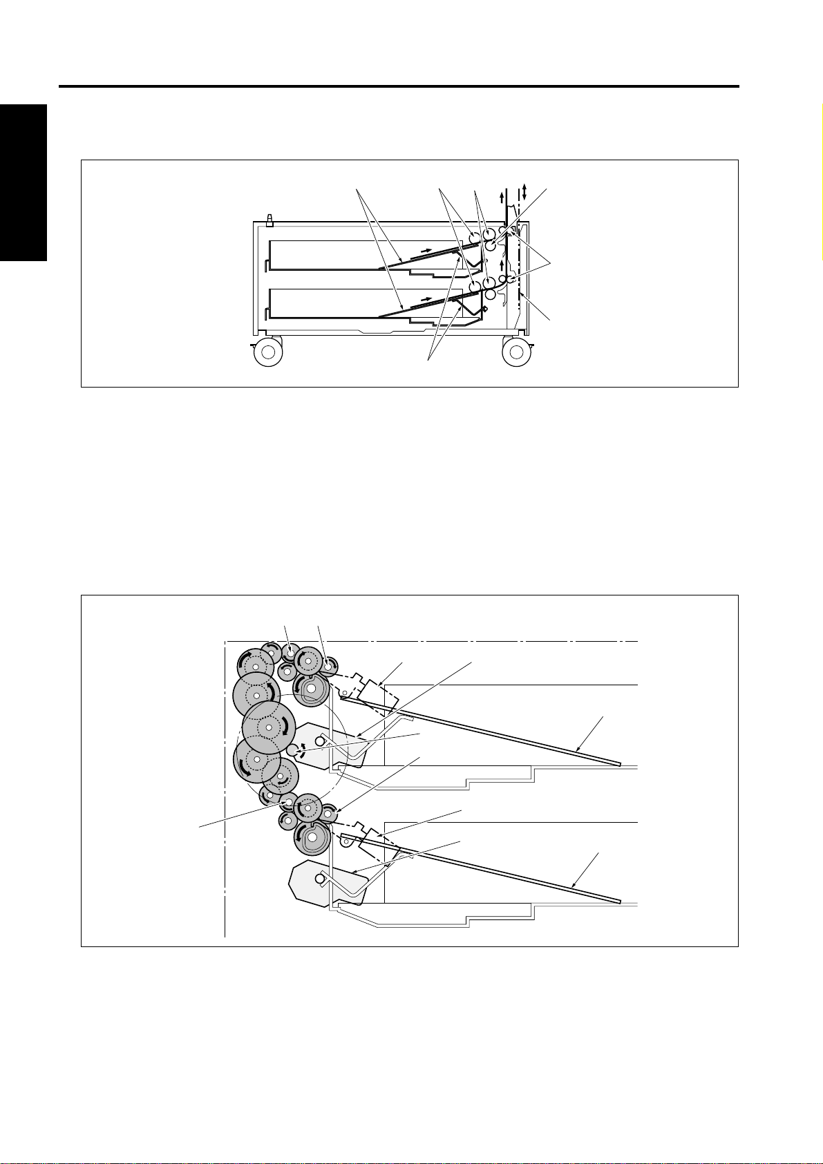
2. CENTER CROSS-SECTIONAL DIAGRAM
I OUTLINE
3. DRIVE SYSTEM DIAGRAM
[4]
[6]
[7]
[1]
[2]
[3]
[5]
[1] Double feed prevention roller [5] Paper lift plate
[2] Conveyance roller [6] Paper feed roller
[3] Paper feed path for the double sided copy [7] Feed roller
[4] Paper lift lever
[10]
[11]
[6]
[7]
[2]
[3]
[8]
[1]
[4]
[5]
[9]
[1] SD101 (Paper feed solenoid /U) [7] M102 (Tray up drive motor /4)
[2] M101 (Tray up drive motor /3) [8] Paper lift plate /L
[3] Paper lift plate /U [9] Conveyance roller
[4] M100 (DB paper feed motor) [10] Conveyance roller
[5] Feed roller /L [11] Feed roller /U
[6] SD102 (Paper feed solenoid /L)
1-2
Page 9
II UNIT EXPLANATION
1. PAPER FEED SECTION
1.1 Composition
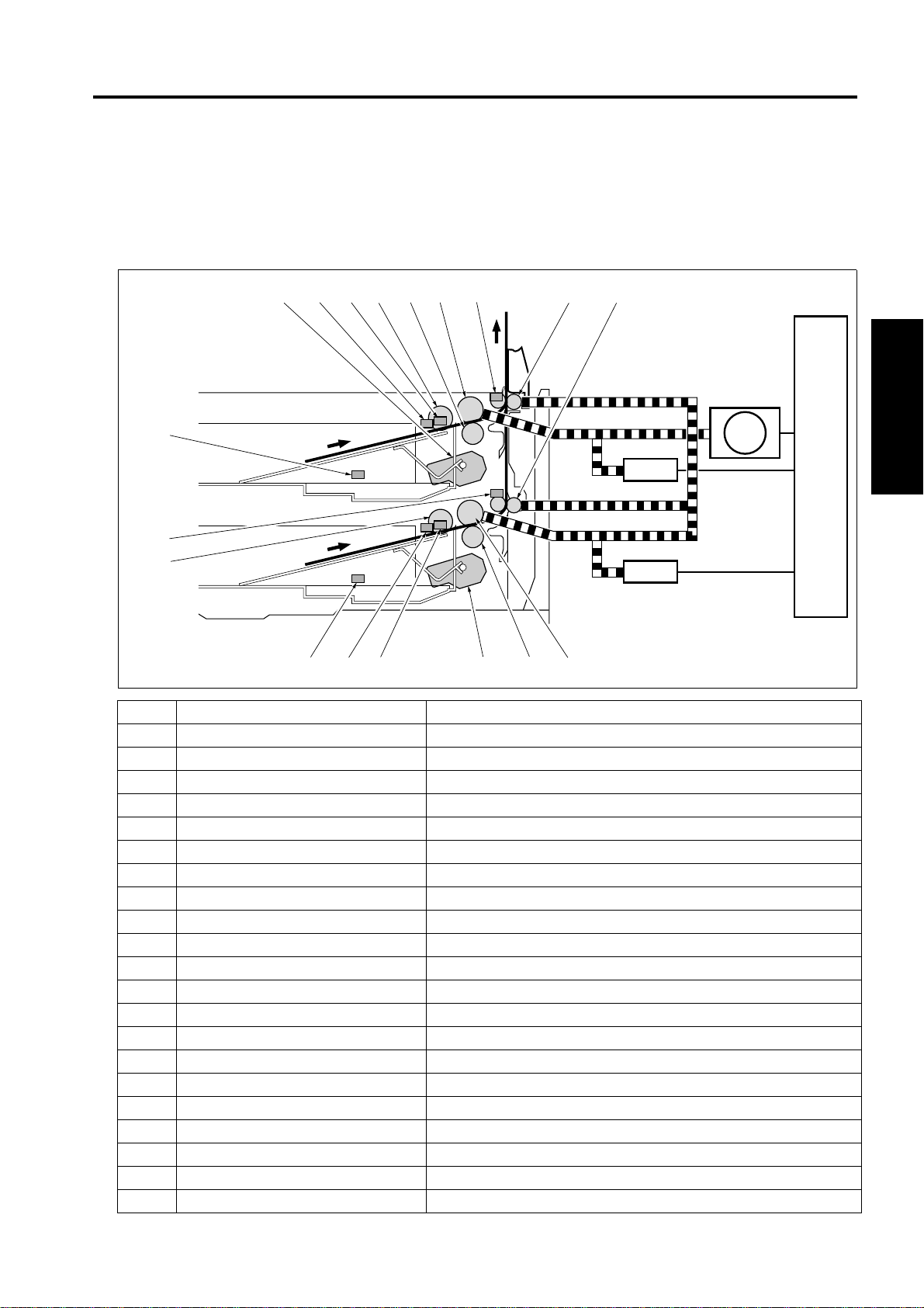
PAPER FEED SECTION
[1] [2][18][17][16][15][14][13][12]
[11]
SD101
[10]
[9]
[3][4][5][6][7][8]
Symbol Name Function or method
[1] Conveyance roller Paper convey anc e
[2] Conveyance roller Paper convey anc e
[3] Feed roller Paper conveyance
[4] Double feed prevention roller Prevent double feed of paper, Torque limiter
[5] M102 (Tray up drive motor /4) Driving of the paper lift plate, 24 VDC brush motor
[6] PS107 (Tray upper limit sensor /4) Detection of the tray paper upper limit
[7] PS108 (No paper sensor /4) Detection of the presence of paper
[8] PS106 (Tray sensor /4) Tray detection and remaining paper detection
[9] Paper feed roller Paper conveyance
[10] PS105 (Paper feed sensor /L) Detection of the paper passage from the lower tray
[11] PS101 (Tray sensor /3) Tray detection and remaining paper detection
[12] M101 (Tray up drive motor /3) Driving of paper lift plate, 24 VDC brushless motor
[13] PS103 (No paper sensor /3) Detection of the presence of paper
[14] PS102 (Tray upper limit sensor /3) Detection of the tray paper upper limit
[15] Paper feed roller Paper conveyance
[16] Double feed prevention roller Prevent double feed of paper, Torque limiter
[17] Feed roll er Paper convey ance
[18] PS104 (Paper feed sensor /U) Detection of the paper passage from the upper tray
M100 DB paper feed motor
SD101 Paper feed solenoid /U Transmission of driving force to the paper feed roller unit
SD102 Paper feed solenoid /L Transmission of driving force to the paper feed roller unit
Driving of the paper feed system, DC brushless mot or PLL control
SD102
M100
DBDB
II UNIT EXPLANATION
2-1
Page 10

PAPER FEED SECTION
1.2 Operation
Since the operation of the uppe r tray is the same as that for the lower tra y, the explanation is given of the
upper tray only.
1.2.1 Tray up drive control
When the paper feed tr ay is set, the PS101 (Tray sensor /3) de tec ts the tr ay to t ur n on the M1 01 (Tray up
drive motor /3). As a result, the paper lift plate in the tray goes up.
When the PS1 02 (Tray upper limi t sensor /3) is turn ed on to de tect th e paper upper li mit, the M1 01 goes
off. When paper is fed and the PS102 is turned off, the M102 lifts the paper lift plat e until the PS102 is
turned on again. When the tray is pulled out, the coupling is released and the paper lift plate goes down by
its own weight.
1.2.2 Paper feed control
II UNIT EXPLANATION
The paper feed s ystems ar e driven by the M 100 (DB pa per feed motor). W hen the S D101 (Pa per feed
solenoid /U) is turned on, the 1st paper feed section feeds paper to the registration section.
2-2
Page 11
PAPER FEED SECTION
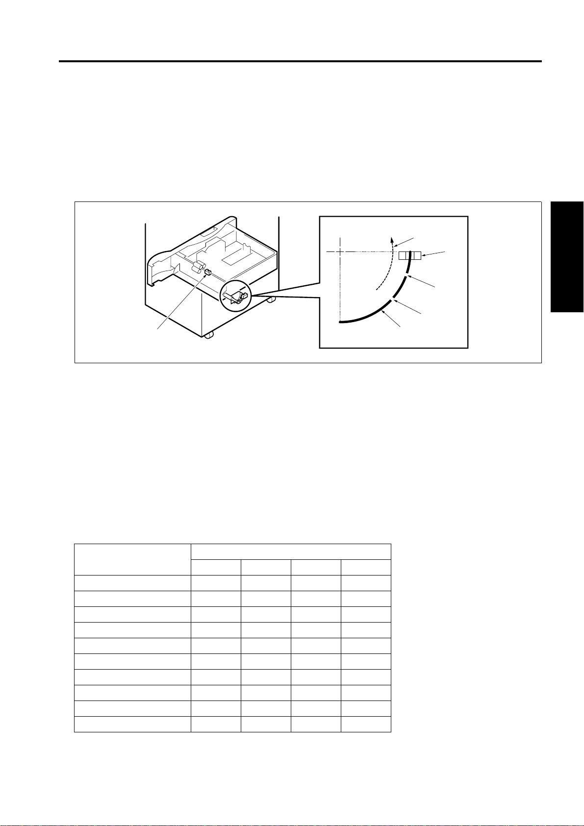
1.2.3 Remaining paper detection control
The remaining paper quantity is detected by the PS101 (Tray sensor /3). The paper lift plate goes up gradually as the quant ity of pape r in the tra y is gettin g reduce d. Interl ocking with the pa per lift plat e that goe s
up, the actuator at th e rea r of the tray rotates . The PS10 1 detects the r emain ing pa per quan tity b y co unting the number of ON/OFF of the slits in the actuator after the tray is loaded.
0 count: Full, 1 count: Medium, 2 counts: Low
No paper detection is made by the PS103 (No paper sensor /3).
[1]
[2]
[3]
[4]
[6]
[1] Direction of rotation when the paper up/down plate rises [4] Slit 2
[2] PS101 (Tray sensor /3) [5] Actuator
[3] Slit 1 [6] PS103 (No paper sensor/3)
1.2.4 Paper size detection
The paper size in the tray can be set by turning the PSDTB /3 (Paper size detection board /3) by hand, and
the DBDB (DB drive b oard) d etects a swit ch sign al acc ording to th e positio n o f the SW 1. The tab le bel ow
shows the relationship between the switch signal and the paper size.
For metric area
Switch signal
Paper size
SIZE A SIZE B SIZE C SIZE D
11 x 17
B5 !
B4 !
A5R !!
A4 !
A4R !!
A3 !!
F4 !!!
8.5 x 11 !
8.5 x 11R !!
[5]
II UNIT EXPLANATION
2-3
Page 12

PAPER FEED SECTION
For inch area
II UNIT EXPLANATION
Paper size
SIZE A SIZE B SIZE C SIZE D
11 x 17
A5R !
A4 !
A4R !!
A3 !
F4 !!
5.5 x 8.5 !!
8.5 x 11 !!!
8.5 x 11R !
8.5 x 14 !!
Switch signal
2-4
Page 13

III DISASSEMBLY/ASSEMBLY
Caution:
• Make sure the power cord of the copier is
unplugged from the power outlet before disassembly or assembly.
1. PAPER FEED SECTION
1.1 Removing and reinstalling the paper feed tray
1. Pull out the pa per feed tr ay [1] and take out the
2 screws [2] on the right side.
2. Remove the paper fe ed tray [1] from the guide
rails [3].
3. Reinstall the above parts following the remova l
steps in reverse.
[2]
PAPER FEED SECTION
1.2 Removing and reinstalling the paper feed unit
1. Remove the paper feed tray.
2. Remove the 4 claws [1] in the arrow-marked
direction, and remove the tray cover [2].
[2]
[1]
[1]
[3]
III DIS./ASSEMBLY
[1]
3-1
Page 14
PAPER FEED SECTION
3. Open the paper feed door, take out the 3 screws
[1] and remove the paper size setting unit [2].
[2]
4. Remove the 3 screws [1] and remove the cover
[2].
[1]
[2]
[1]
III DIS./ASSEMBLY
5. Remove the paper size setting unit connector
[1].
3-2
[1]
Page 15
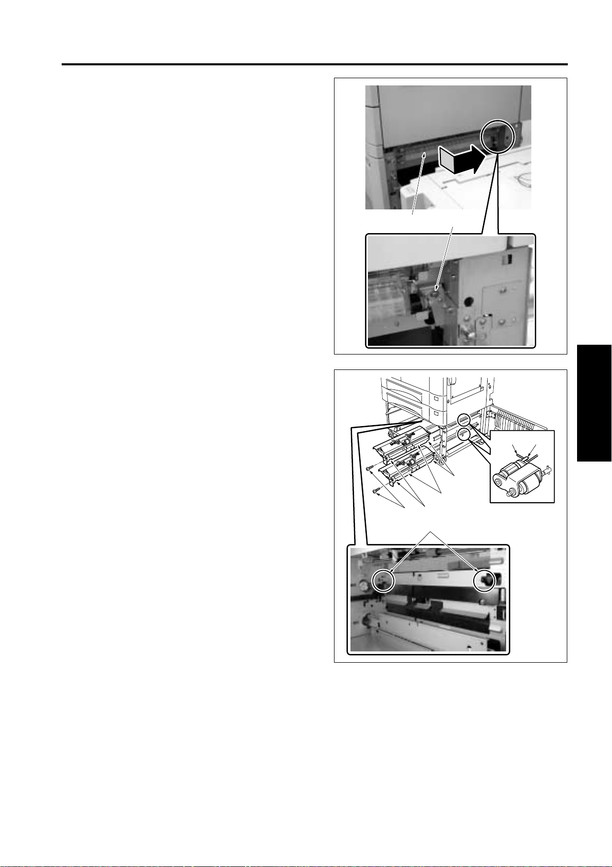
6. When the LT is installed, remove the screw [1]
and then remove the LT guide plate unit [2].
PAPER FEED SECTION
7. Remove each of the screws [1] in dicated by the
arrow mark, and then remove the paper feed
unit [2] to forward.
8. Reinstall the above parts following the remova l
steps in reverse.
Note:
• Be sure t o install the paper feed unit [2] s o that
the arrow mark impressed on the notched section
[3] of the paper feed unit [2] comes above the
hook [4].
• Install the paper feed un it [2] so that th e hook [5]
of the paper feed rol ler holder comes above the
paper feed roller release arm [6].
[2]
[1]
[3]
[4]
[2]
[1]
[3]
[6] [5]
III DIS./ASSEMBLY
3-3
Page 16
PAPER FEED SECTION
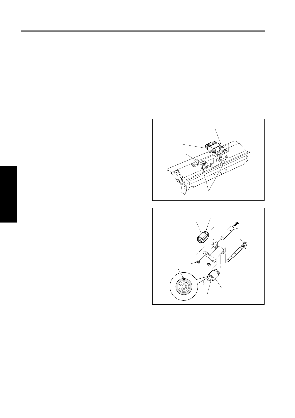
1.3 Replacing the paper feed rubber and the feed rubber
A. Periodically replaced parts/cycle
• Paper feed rubber: Every 480,000 cop ies (once
for every 200,000 copies for actual durable
count)
• Feed rubber: Every 480,000 copies (once for
every 200,000 copies for actual durable count)
B. Procedure
1. Remove the paper feed unit.
2. Remove the 2 stop ri ngs [1] and the front side
bearing [2]. Then slide the re ar side bearing [3]
to the rear to remove the paper fee d roller unit
[4].
[3]
[4]
[2]
[1]
III DIS./ASSEMBLY
3. Remove the collar [1] and pull out the feed shaft
[2].
4. Remove the feed rubber [4] from the feed roller
[3].
5. Remove the stop ring [5] and pul l out the paper
feed shaft [6].
6. Remove the paper feed rubber [8] from the
paper feed roller [7].
7. Reinstall the above par ts following the removal
steps in reverse.
Note:
• Be su re to install the feed rubber [4] so that the
paint mark [9] turns in the direction show n in the
drawing.
[9]
[5]
[8]
[7]
[6]
[2]
[1]
[4]
[3]
3-4
Page 17
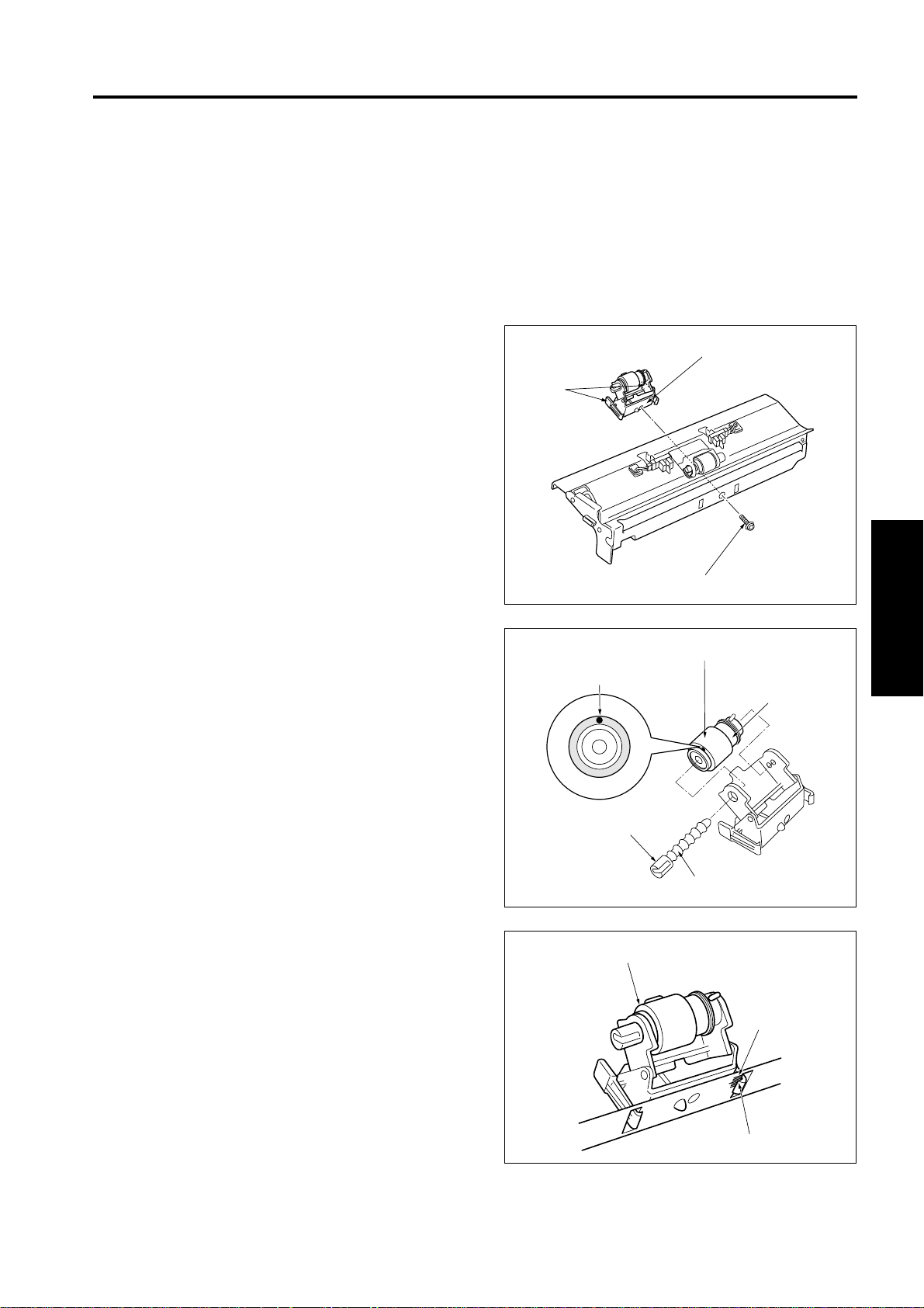
1.4 Replacing the double feed prevention rubber
A. Periodically replaced parts/cycle
• Double feed prevention rubber: Every 480,000
copies (once for every 2 00,000 cop ies for actua l
durable count)
B. Procedure
1. Remove the paper feed unit.
2. Remove the screw [1].
3. Pushing the knobs [2] on both sides with your
fingers and remove the double feed prevention
roller unit [3].
PAPER FEED SECTION
[3]
[2]
4. While pushing the lever [2] of the lever click
shaft [1], pull out the lever click shaft [1] and
remove the double feed prevention roller.
5. Remove the double feed prevention rubber [4]
from the double feed prevention roller [3].
6. Reinstall the above parts following the remova l
steps in reverse.
Note:
• Be su re to in stall the double f eed preven tion rub ber so that the paint mark [5 ] shown abo ve turns
in the direction shown in the drawing.
• When ins talling the double feed preventi on roller
unit [1], be sure to align the upper section of the
claw [2] with the center (the lo ngest scale) of the
marking [3] impressed on the plate for leveling.
[5]
[1]
[4]
III DIS./ASSEMBLY
[3]
[2]
[1]
[1]
[3]
[2]
3-5
Page 18

PAPER FEED SECTION
III DIS./ASSEMBLY
Blank page
3-6
Page 19

PARTS CATALOG
Models
DB-211/DB-411
NOVEMBER 2002
KONICA BUSINESS TECHNOLOGIES, INC.
Page 20

Page 21

How to use this catalog
This parts catalog includes illustrations and part numbers for all replacement parts and assemblies used in this model.
Model-specific parts are identified in the illustrations with reference
numbers. Use the reference number to locate the corresponding part
number on the facing page.
Common hardware items, such as screws, nuts, washers, and pins, are
identified in the illustrations with reference letters. Use the reference letter to locate the corresponding part number on the hardware listing in the
lower right hand corner of the facing page.
If you know a part number, but don’t know where the part is used, use
the numerical index to determine the page number and reference number for that part. Because some common parts are used in several
places, there may be more than one entry. Refer to the illustrations to see
where the part may be used.
If you know a part’s description, but don’t know where to look to find
the part number, use the alphabetical index to determine likely page and
reference numbers. Then look at the illustrations to determine that you
have identified the correct part. Locate the part number using the listing
on the opposite page.
Retail pricing that appears with the numerical index, while valid when
this catalog was printed, is subject to change without notice. The prices
are only suggested prices and are provided only for reference. Dealers
may determine their own selling prices. For up-to-date pricing, refer to
current Konica price lists or contact the Konica Parts Distribution Center.
How to order parts
Use standard Konica parts ordering procedures to obtain these parts.
For ordering options, contact Konica’s Parts Distribution Center.
When ordering parts, be sure to specify part numbers exactly as listed in
this catalog.
NOTE: Electrical parts may include previously used components.
Model DB-211/411 Konica Business Technologies, Inc. Page iii
1st Edition November, 2002
Page 22

This page left blank intentionally.
Page iv Konica Business Technologies, Inc. Model DB-211/411
November, 2002 1st Edition
Page 23

How to use this catalog . . . . . . . . . . . . . . . . . . . . . . . . . iii
Contents . . . . . . . . . . . . . . . . . . . . . . . . . . . . 1
DB-211 . . . . . . . . . . . . . . . . . . . . . . . . . . . . 2
Wiring . . . . . . . . . . . . . . . . . . . . . . . . . . . . 12
DB-411 . . . . . . . . . . . . . . . . . . . . . . . . . . . . 14
Wiring . . . . . . . . . . . . . . . . . . . . . . . . . . . . 24
Alphabetical Index . . . . . . . . . . . . . . . . . . . . . . . . . . . 27
Numerical Index . . . . . . . . . . . . . . . . . . . . . . . . . . . . 29
Contents
Model DB-211/411 Konica Business Technologies, Inc. Page 1
1st Edition November, 2002
Page 24

DB-211
Page 2 Konica Business Technologies., Inc. Model DB-211/411
November, 2002 1st Edition
Page 25

REF. PART NUMBER DESCRIPTION
NO.
1 26NA47350 Cassette stopper
2 13HA-1071 Main support plate right assembly
3 13GU12051 Cassette detecting cover
4 049810030 Carriage roller/F
5 56AA85510 Photosensor
6 13HA40061 Actuator/upper
7 13HA40070 Roller spring
8 13GU40110 Shaft holder part
9 13SY90030 LCT wiring/2
10 13HA40022 Paper feed connecting roller/3
11 26NA40820 Paper feed slide shaft holder
12 26NA40270 Side guide plate
13 049810020 Carriage roller/R
14 13HA40150 Paper feed driven shaft holder
15 26NA40890 Slide shaft holder
16 26NA40681 Paper feed driven roller/lower
17 13HA10530 Guide sheet/2
18 13HA10370 Main positioning shaft
19 13HA-1090 Main support plate left assembly
HARDWARE
REF.
LTR.
a 00Z283061
b 00Z193061
c 00Z183061
d 00Z283081
e 00Z670206
f 00Z921941
g 00Z194101
h 00Z253081
i 00Z670606
j 00Z183121
k 00Z924316
PART
NUMBER
Model DB-211/411 Konica Business Technologies., Inc. Page 3
1st Edition November, 2002
Page 26

DB-211
Page 4 Konica Business Technologies., Inc. Model DB-211/411
November, 2002 1st Edition
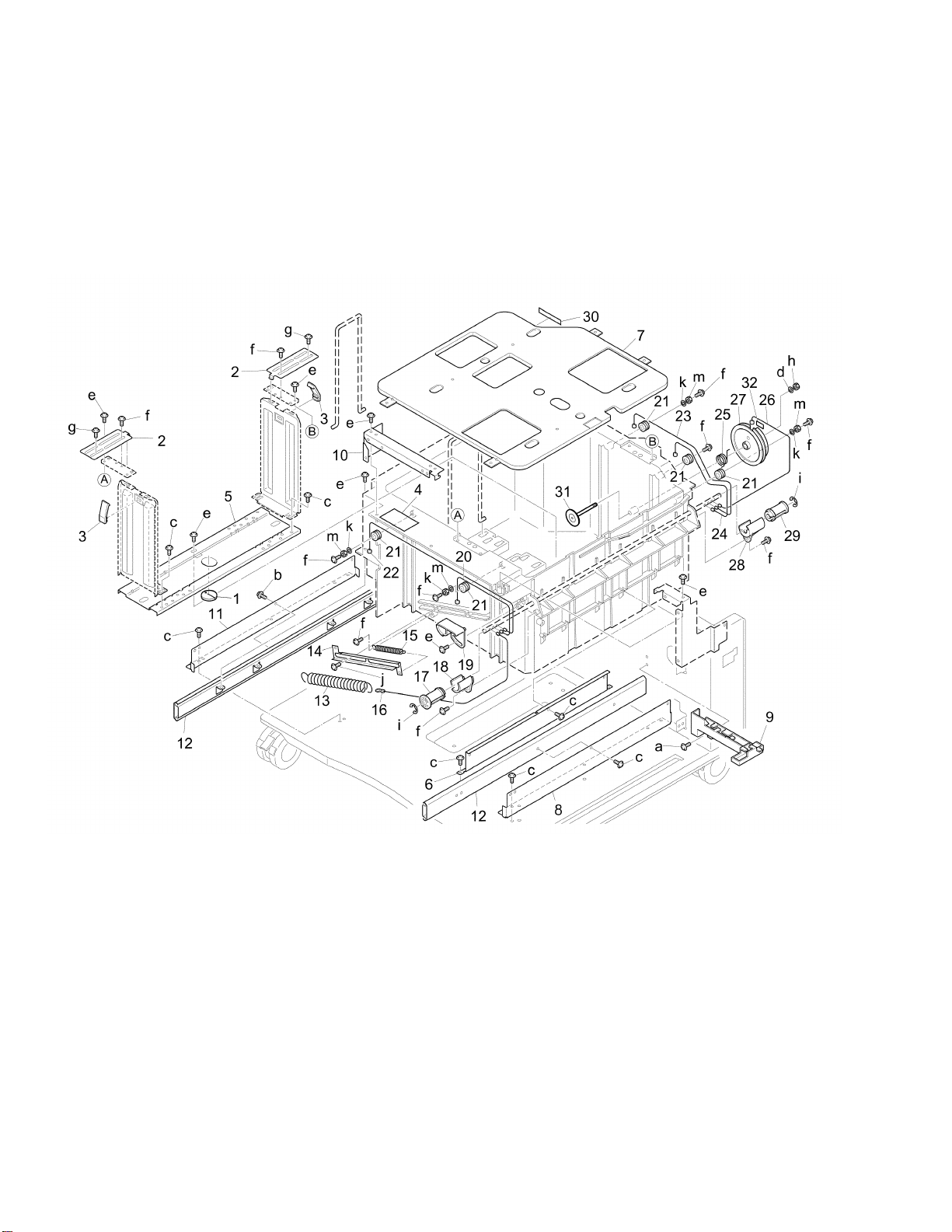
Page 27

REF. PART NUMBER DESCRIPTION
NO.
1 13HA12061 Side cover/left
2 13SW12040 Front fixed cover
3 26NA53931 Fixed screw
4 13HA12150 Cord cover
5 13HA12081 Side cover/right
6 13HA12021 Door/right
7 13HA10470 Door fulcrum part
8 13HA10461 Door fulcrum plate
9 13HA40080 Guide plate/middle
10 26NA50091 Open-close knob
11 26NA50080 Lock claw
12 13HA12160 Lock spring/upper
13 13HA12170 Lock spring/lower
14 26NA50630 Shaft holder part/upper
15 26NA50640 Shaft holder part/lower
16 466078010 Pin A
17 13HA10341 Hinge plate/A
18 13HA-1260 Guide plate/B assembly
19 13HA10550 Spacer/A
20 26NA10062 Cassette rail/right
21 13HA10171 Actuator/lower
22 13HA12070 Rear cover
HARDWARE
REF.
LTR.
a 00Z283081
b 00Z193061
c 00Z283061
d 00Z193062
e 00Z253081
f 00Z670256
g 00Z254081
h 00Z670306
i 00Z193081
PART
NUMBER
Model DB-211/411 Konica Business Technologies., Inc. Page 5
1st Edition November, 2002
Page 28
DB-211
Page 6 Konica Business Technologies., Inc. Model DB-211/411
November, 2002 1st Edition
Page 29

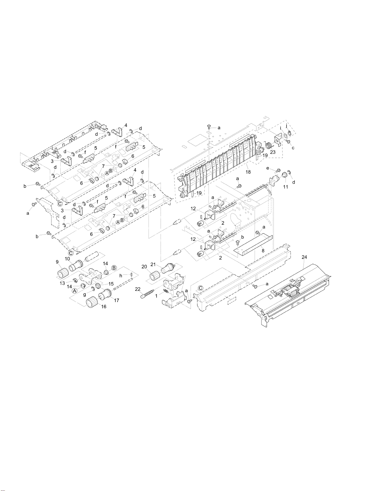
REF. PART NUMBER DESCRIPTION
NO.
1 40AA40450 Double feed pressure spring
2 13HA-4040 Paper feed driving shaft/rear
3 26NA40281 Paper detecting actuator
4 26NA40751 Paper detecting actuator/2
5 56AA85510 Photosensor
6 26NA40700 Shaft positioning part
7 540076010 Paper feed shaft holder
8 13GU40100 Shaft holder mount plate
9 26NA40090 Paper feeding rubber
10 26NA40080 Feeding roller
11 26NA16310 Paper feed gear (Z=20)
12 13GU40110 Shaft holder part
13 40AA40150 Shaft positioning part
14 40AA76040 Feeding shaft holder
15 26NA40510 Paper feed idler gear (Z=17)
16 26NA40110 Double feed preventive rubber/upper
17 26NA40101 Double feed preventive roller/upper
18 13SY-1130 Guide plate/middle assembly
19 13HA10560 Guide sheet/3
20 26NA40120 Double feed preventive rubber/lower
21 26NA40500 Double feed preventive roller
22 40AA40181 Lever click shaft
23 13HA10450 Paper feed rotary spring
24 13SW-4001 Paper feed assembly
HARDWARE
REF.
LTR.
a 00Z193061
b 00Z253081
c 00Z194061
d 00Z670306
e 00Z193051
f 00Z183121
g 00Z670406
h 00Z712106
i 00Z610501
j 00Z600506
PART
NUMBER
Model DB-211/411 Konica Business Technologies., Inc. Page 7
1st Edition November, 2002
Page 30

DB-211
Page 8 Konica Business Technologies., Inc. Model DB-211/411
November, 2002 1st Edition
Page 31

REF. PART NUMBER DESCRIPTION
NO.
1 13SW-1500 Drive unit
2 13HA-1540 Solenoid mount plate assembly
3 26NA82511 Paper feed solenoid
4 26NA40830 Positioning arm
5 26NA40760 Lever hold spring
6 13HA10431 Wiring guide part/B
7 13HA40022 Paper feed connecting roller/3
8 26NA40820 Paper feed slide shaft holder
9 13HA77060 Driving gear (Z=15)
10 26WA80011 DC Brushers motor/20
11 25BA47461 Cassette positioning catch/U
12 26NA80041 Cassette driving motor
13 13SY77050 Idler gear/D (Z=17)
14 13SY77020 Idler gear/A (Z=31/64)
15 13SY77030 Idler gear/B (Z=29/33)
16 13HA77040 Idler gear/C (Z=16/31)
17 26NA-1680 Paper gear/2 assembly
18 13HA77080 Idler gear/F (Z=16)
19 13HA15110 Spacer
20 40AA32320 Toner supply spacer
21 26NA47390 Cassette fixed spring
22 13HA77090 Paper feed coupling gear/A
23 13SW-9010 PFU driving board assembly
24 26NA17490 Paper feed coupling gear/B (Z=20)
HARDWARE
REF.
LTR.
a 00Z193061
b 00Z283061
c 00Z670406
d 00Z670306
e 00Z163051
f 00Z183043
g 00Z925106
h 00Z670606
i 00Z193201
j 00Z184081
PART
NUMBER
Model DB-211/411 Konica Business Technologies., Inc. Page 9
1st Edition November, 2002
Page 32

DB-211
Page 10 Konica Business Technologies., Inc. Model DB-211/411
November, 2002 1st Edition
Page 33

REF. PART NUMBER DESCRIPTION
NO.
1 40LA47040 Paper feed regulating plate/left
2 26NA-4740 Lift-up bottom plate assembly
3 26WA47221 Cassette stay/lower
4 40AA47130 Adjusting plate
5 40AA77290 Pinion (Z=16)
6 26NA47390 Cassette fixed spring
7 25BA47461 Cassette positioning catch/U
8 26NA47291 Cassette remained detecting actuator
9 26NA47301 Ground plate
10 40LA-4720 Side regulating plate/front assembly
11 26NA97300 Cassette click label
12 26NA47260 Paper feed indicating plate/front
13 26NA47240 Cassette detecting connector
14 26NA47251 Cassette detecting base
15 26NA-9200 Size detecting board assembly
16 26NA47280 Spring lock plate
17 26NF97290 Cassette indication label/lower
18 26NA-4730 Side regulating plate/rear assembly
19 26NA47381 Fixing seal
20 40LA47020 Cassette base/lower
HARDWARE
REF.
LTR.
a 00Z670406
b 00Z670606
c 00Z620301
d 00Z254081
e 00Z254121
f 00Z610301
g 00Z283061
h 00Z253081
i 00Z254101
j 00Z463103
PART
NUMBER
Model DB-211/411 Konica Business Technologies., Inc. Page 11
1st Edition November, 2002
Page 34

WIRING
Page 12 Konica Business Technologies., Inc. Model DB-211/411
November, 2002 1st Edition
Page 35

REF. PART NUMBER DESCRIPTION
NO.
1 13GU90010 PFU wiring/1
2 13GU90020 PFU wiring/2
3 13SY90010 LCT electrify wiring
4 26WA90330 Relay wiring/3
5 13SY90030 LCT wiring/2
6 13SY90040 LCT wiring/3
7 13SY90060 LCT wiring/5
8 13NE90020 LCT wiring/1
Model DB-211/411 Konica Business Technologies., Inc. Page 13
1st Edition November, 2002
Page 36

DB-411
Page 14 Konica Business Technologies., Inc. Model DB-211/411
November, 2002 1st Edition
Page 37

REF. PART NUMBER DESCRIPTION
NO.
1 13HA10540 Protection sheet
2 13HA-9720 Cassette label assembly
3 26NA47260 Paper feed indicating plate/front
4 26NA47240 Cassette detecting connector
5 26NA-9200 Size detecting board assembly
6 26NA47251 Cassette detecting base
7 26NA47280 Spring lock plate
8 049810030 Carriage roller/F
9 13GU40110 Shaft holder part
10 56AA85510 Photosensor
11 13HA40061 Actuator/upper
12 13SY90030 LCT wiring/2
13 13HA10370 Main positioning shaft
14 13HA40022 Paper feed connecting roller/3
15 26NA40820 Paper feed slide shaft holder
16 26NA40270 Side guide plate
17 13HA40070 Roller spring
18 13HA40150 Paper feed driven shaft holder
19 26NA40890 Slide shaft holder
20 26NA40681 Paper feed driven roller/lower
21 13HA-1090 Main support plate left assembly
22 049810020 Carriage roller/R
23 13HA10530 Guide sheet/2
24 13HA-1071 Main support plate right assembly
HARDWARE
REF.
LTR.
a 00Z283061
b 00Z193061
c 00Z183061
d 00Z283081
e 00Z924316
f 00Z253081
g 00Z194101
h 00Z183121
i 00Z921941
j 00Z670206
k 00Z670606
PART
NUMBER
Model DB-211/411 Konica Business Technologies., Inc. Page 15
1st Edition November, 2002
Page 38

DB-411
Page 16 Konica Business Technologies., Inc. Model DB-211/411
November, 2002 1st Edition
Page 39

REF. PART NUMBER DESCRIPTION
NO.
1 13HA12061 Side cover/left
2 13SY12190 Front fixed cover
3 13SY12010 Front cover
4 26NA53931 Fixed screw
5 13HA12150 Cord cover
6 13HA12081 Side cover/right
7 13HA12021 Door/right
8 13HA10470 Door fulcrum part
9 13HA10461 Door fulcrum plate
10 13HA40080 Guide plate/middle
11 26NA50080 Lock claw
12 13HA12160 Lock spring/upper
13 13HA12170 Lock spring/lower
14 26NA50630 Shaft holder part/upper
15 26NA50640 Shaft holder part/lower
16 466078010 Pin A
17 26NA50091 Open-close knob
18 13HA10341 Hinge plate/A
19 13HA-1260 Guide plate/B assembly
20 13HA10550 Spacer/A
21 13HA12070 Rear cover
22 13HA10171 Actuator/lower
HARDWARE
REF.
LTR.
a 00Z283081
b 00Z193061
c 00Z283061
d 00Z193062
e 00Z670256
f 00Z670306
g 00Z254081
h 00Z253081
i 00Z163101
PART
NUMBER
Model DB-211/411 Konica Business Technologies., Inc. Page 17
1st Edition November, 2002
Page 40

DB-411
Page 18 Konica Business Technologies., Inc. Model DB-211/411
November, 2002 1st Edition
Page 41

REF. PART NUMBER DESCRIPTION
NO.
1 13SY-4001 Paper feed assembly
2 13HA-4040 Paper feed driving shaft/rear
3 13HA40172 Paper detecting actuator/front
4 13HA40161 Paper detecting actuator/rear
5 56AA85510 Photosensor
6 26NA40700 Shaft positioning part
7 540076010 Paper feed shaft holder
8 40AA40450 Double feed pressure spring
9 26NA40090 Paper feeding rubber
10 26NA40080 Feeding roller
11 26NA16310 Paper feed gear (Z=20)
12 13GU40110 Shaft holder part
13 40AA40150 Shaft positioning part
14 40AA76040 Feeding shaft holder
15 26NA40510 Paper feed idler gear (Z=17)
16 26NA40110 Double feed preventive rubber/upper
17 26NA40101 Double feed preventive roller/upper
18 13SY-1130 Guide plate/middle assembly
19 13HA10560 Guide sheet/3
20 26NA40120 Double feed preventive rubber/lower
21 26NA40500 Double feed preventive roller
22 40AA40181 Lever click shaft
23 13HA10450 Paper feed rotary spring
HARDWARE
REF.
LTR.
a 00Z193061
b 00Z253081
c 00Z194061
d 00Z670306
e 00Z193051
f 00Z183121
g 00Z670406
h 00Z712106
i 00Z610501
j 00Z600506
PART
NUMBER
Model DB-211/411 Konica Business Technologies., Inc. Page 19
1st Edition November, 2002
Page 42

DB-411
Page 20 Konica Business Technologies., Inc. Model DB-211/411
November, 2002 1st Edition
Page 43

REF. PART NUMBER DESCRIPTION
NO.
1 13SY-1500 Drive unit
2 13HA-1540 Solenoid mount plate assembly
3 26NA82511 Paper feed solenoid
4 26NA40830 Positioning arm
5 26NA40760 Lever hold spring
6 26WA80011 DC Brushers motor/20
7 13HA40022 Paper feed connecting roller/3
8 26NA40820 Paper feed slide shaft holder
9 13HA77060 Driving gear (Z=15)
10 26NA47390 Cassette fixed spring
11 25BA47461 Cassette positioning catch/U
12 13HA80020 LCT driving motor
13 13SY77050 Idler gear/D (Z=17)
14 13SY77020 Idler gear/A (Z=31/64)
15 13SY77030 Idler gear/B (Z=29/33)
16 13HA77040 Idler gear/C (Z=16/31)
17 26NA-1680 Paper gear/2assembly
18 13HA77080 Idler gear/F (Z=16)
19 13HA15110 Spacer
20 40AA32320 Toner supply spacer
21 26NA17490 Paper feed coupling gear/B (Z=20)
22 13HA77090 Paper feed coupling gear/A
23 13SY-9010 LCT driving board assembly
HARDWARE
REF.
LTR.
a 00Z193061
b 00Z283061
c 00Z670406
d 00Z670306
e 00Z163051
f 00Z183043
g 00Z925106
h 00Z670606
i 00Z193301
j 00Z184081
PART
NUMBER
Model DB-211/411 Konica Business Technologies., Inc. Page 21
1st Edition November, 2002
Page 44
DB-411
Page 22 Konica Business Technologies., Inc. Model DB-211/411
November, 2002 1st Edition
Page 45

REF. PART NUMBER DESCRIPTION
NO.
1 13HA47380 Adjusting cam
2 13HA47250 Reinforcing plate
3 540047200 Paper regulating claw
4 13HA97051 LCT guide label
5 12RQ47030 Paper adjusting plate
6 13HA47170 Main mount plate/right
7 12RQ47020 Paper guide plate
8 13HA10130 Rail mount plate/right
9 13HA10431 Wiring guide part/B
10 13HA12130 External mount plate/3
11 13HA10140 Rail mount plate/left
12 13HA10161 LCT slide rail
13 13HA47140 Driving auxiliary spring/A
14 26NA47410 Spring mount plate
15 13HA47150 Driving auxiliary spring/B
16 12RQ47160 Auxiliary wire
17 12RQ47090 Wire driving pulley/front
18 12RQ47110 Pulley fixed part/front
19 12RQ47230 Wire adjusting part
20 13HA47100 Lift-up wire/1
21 13HA47210 Wire pulley
22 13HA47110 Lift-up wire/2
23 13HA47220 Lift-up wire/4
24 13HA47120 Lift-up wire/3
25 13HA47191 Detecting spring
26 13HA47130 Detecting wire
27 13HA47091 Detecting plate
28 13HA47260 Pulley fixed part/rear
29 13HA47370 Driving pulley
30 13HA47330 Slide sheet
31 13HA-4790 Fulcrum shaft assembly
32 13HA47340 Stopper/A
HARDWARE
REF.
LTR.
PART
NUMBER
a 00Z193061
b 00Z193051
c 00Z283061
d 00Z510401
e 00Z254081
f 00Z183201
g 00Z163081
h 00Z610421
i 00Z670406
j 00Z193041
k 00Z610321
m 00Z510301
Model DB-211/411 Konica Business Technologies., Inc. Page 23
1st Edition November, 2002
Page 46

WIRING
Page 24 Konica Business Technologies., Inc. Model DB-211/411
November, 2002 1st Edition
Page 47

REF. PART NUMBER DESCRIPTION
NO.
1 13SY90010 LCT electrify wiring
2 13NE90020 LCT wiring/1
3 13SY90040 LCT wiring/3
4 13SY90030 LCT wiring/2
5 13SY90050 LCT wiring/4
6 13SY90060 LCT wiring/5
7 26WA90330 Relay wiring/3
Model DB-211/411 Konica Business Technologies., Inc. Page 25
1st Edition November, 2002
Page 48

This page left blank intentionally.
Page 26 Konica Business Technologies, Inc. Model DB-211/411
November, 2002 1st Edition
Page 49

ALPHABETICAL INDEX
PART PAGE REF.
DESCRIPTION NO. NO.
A
Actuator/lower . . . . . . . 5 21
Actuator/lower . . . . . . . 17 22
Actuator/upper . . . . . . . 3 6
Actuator/upper . . . . . . . 15 11
Adjusting cam . . . . . . . 23 1
Adjusting plate . . . . . . . 11 4
Auxiliary wire . . . . . . . . 23 16
C
Carriage roller/F . . . . . . 3 4
Carriage roller/F . . . . . . 15 8
Carriage roller/R . . . . . . 3 13
Carriage roller/R . . . . . . 15 22
Cassette base/lower . . . . 11 20
Cassette click label . . . . . 11 11
Cassette detecting base . . 11 14
Cassette detecting base . . 15 6
Cassette detecting connector 11 13
Cassette detecting connector 15 4
Cassette detecting cover . . 3 3
Cassette driving motor . . . 9 12
Cassette fixed spring . . . . 9 21
Cassette fixed spring . . . . 11 6
Cassette fixed spring . . . . 21 10
Cassette indication
label/lower . . . . . . . 11 17
Cassette label assembly . . 15 2
Cassette positioning catch/U 9 11
Cassette positioning catch/U 11 7
Cassette positioning catch/U 21 11
Cassette rail/right . . . . . 5 20
Cassette remained detecting
actuator . . . . . . . . 11 8
Cassette stay/lower . . . . 11 3
Cassette stopper . . . . . . 3 1
Cord cover . . . . . . . . . 5 4
Cord cover . . . . . . . . . 17 5
D
DC motor/20 . . . . . . . . 9 10
DC motor/20 . . . . . . . . 21 6
Detecting plate . . . . . . . 23 27
Detecting spring . . . . . . 23 25
Detecting wire . . . . . . . 23 26
Door fulcrum part . . . . . 5 7
Door fulcrum part . . . . . 17 8
Door fulcrum plate . . . . . 5 8
Door fulcrum plate . . . . . 17 9
Door/right . . . . . . . . . 5 6
Door/right . . . . . . . . . 17 7
Double feed pressure spring 7 1
Double feed pressure spring 19 8
Double feed preventive roller 7 21
Double feed preventive roller 19 21
Double feed preventive
roller/upper . . . . . . 7 17
Double feed preventive
roller/upper . . . . . . 19 17
PART PAGE REF.
DESCRIPTION NO. NO.
Double feed preventive
rubber/upper . . . . . . 7 16
Double feed preventive
rubber/lower . . . . . . 7 20
Double feed preventive
rubber/upper . . . . . . 19 16
Double feed preventive
rubber/lower . . . . . . 19 20
Drive unit . . . . . . . . . . 9 1
Drive unit . . . . . . . . . . 21 1
Driving auxiliary spring/A . . 23 13
Driving auxiliary spring/B . . 23 15
Driving gear (Z=15) . . . . . 9 9
Driving gear (Z=15) . . . . . 21 9
Driving pulley . . . . . . . . 23 29
E
External mount plate/3 . . . 23 10
F
Feeding roller . . . . . . . . 7 10
Feeding roller . . . . . . . . 19 10
Feeding shaft holder . . . . 7 14
Feeding shaft holder . . . . 19 14
Fixed screw . . . . . . . . . 5 3
Fixed screw . . . . . . . . . 17 4
Fixing seal . . . . . . . . . 11 19
Front cover . . . . . . . . . 17 3
Front fixed cover . . . . . . 5 2
Front fixed cover . . . . . . 17 2
Fulcrum shaft assembly . . 23 31
G
Ground plate . . . . . . . . 11 9
Guide plate/B assembly . . 5 18
Guide plate/B assembly . . 17 19
Guide plate/middle . . . . . 5 9
Guide plate/middle . . . . . 17 10
Guide plate/middle assembly 7 18
Guide plate/middle assembly 19 18
Guide sheet/2 . . . . . . . 3 17
Guide sheet/2 . . . . . . . 15 23
Guide sheet/3 . . . . . . . 7 19
Guide sheet/3 . . . . . . . 19 19
H
Hinge plate/A . . . . . . . . 5 17
Hinge plate/A . . . . . . . . 17 18
I
Idler gear/A (Z=31/64) . . . 9 14
Idler gear/A (Z=31/64) . . . 21 14
Idler gear/B (Z=29/33) . . . 9 15
Idler gear/B (Z=29/33) . . . 21 15
PART PAGE REF.
DESCRIPTION NO. NO.
Idler gear/C (Z=16/31) . . . 9 16
Idler gear/C (Z=16/31) . . . 21 16
Idler gear/D (Z=17) . . . . . 9 13
Idler gear/D (Z=17) . . . . . 21 13
Idler gear/F (Z=16) . . . . . 9 18
Idler gear/F (Z=16) . . . . . 21 18
L
LCT driving board assembly 21 23
LCT driving motor . . . . . 21 12
LCT electrify wiring . . . . . 13 3
LCT electrify wiring . . . . . 25 1
LCT guide label . . . . . . . 23 4
LCT slide rail . . . . . . . . 23 12
LCT wiring/1 . . . . . . . . 13 8
LCT wiring/1 . . . . . . . . 25 2
LCT wiring/2 . . . . . . . . 3 9
LCT wiring/2 . . . . . . . . 13 5
LCT wiring/2 . . . . . . . . 15 12
LCT wiring/2 . . . . . . . . 25 4
LCT wiring/3 . . . . . . . . 13 6
LCT wiring/3 . . . . . . . . 25 3
LCT wiring/4 . . . . . . . . 25 5
LCT wiring/5 . . . . . . . . 13 7
LCT wiring/5 . . . . . . . . 25 6
Lever click shaft . . . . . . . 7 22
Lever click shaft . . . . . . . 19 22
Lever hold spring . . . . . . 9 5
Lever hold spring . . . . . . 21 5
Lift-up bottom plate assembly 11 2
Lift-up wire/1 . . . . . . . . 23 20
Lift-up wire/2 . . . . . . . . 23 22
Lift-up wire/3 . . . . . . . . 23 24
Lift-up wire/4 . . . . . . . . 23 23
Lock claw . . . . . . . . . . 5 11
Lock claw . . . . . . . . . . 17 11
Lock spring/lower . . . . . . 5 13
Lock spring/lower . . . . . . 17 13
Lock spring/upper . . . . . . 5 12
Lock spring/upper . . . . . . 17 12
M
Main mount plate/Right . . . 23 6
Main positioning shaft . . . 3 18
Main positioning shaft . . . 15 13
Main support plate left
assembly . . . . . . . . 3 19
Main support plate left
assembly . . . . . . . . 15 21
Main support plate right
assembly . . . . . . . . 3 2
Main support plate right
assembly . . . . . . . . 15 24
O
Open-close knob . . . . . . 5 10
Open-close knob . . . . . . 17 17
Model DB-211/411 Konica Business Technologies, Inc. Page 27
1st Edition November, 2002
Page 50

PART PAGE REF.
DESCRIPTION NO. NO.
P
PFU driving board assembly 9 23
PFU wiring/1 . . . . . . . . 13 1
PFU wiring/2 . . . . . . . . 13 2
Paper adjusting plate . . . . 23 5
Paper detecting actuator . . 7 3
Paper detecting actuator/2 . 7 4
Paper detecting actuator/front 19 3
Paper detecting actuator/rear 19 4
Paper feed assembly . . . . 7 24
Paper feed assembly . . . . 19 1
Paper feed connecting
roller/3 . . . . . . . . . 3 10
Paper feed connecting
roller/3 . . . . . . . . . 9 7
Paper feed connecting
roller/3 . . . . . . . . . 15 14
Paper feed connecting
roller/3 . . . . . . . . . 21 7
Paper feed coupling gear/A . 9 22
Paper feed coupling gear/A . 21 22
Paper feed coupling gear/B
(Z=20) . . . . . . . . . 9 24
Paper feed coupling gear/B
(Z=20) . . . . . . . . . 21 21
Paper feed driven roller/lower 3 16
Paper feed driven roller/lower 15 20
Paper feed driven shaft
holder . . . . . . . . . 3 14
Paper feed driven shaft
holder . . . . . . . . . 15 18
Paper feed driving shaft/rear 7 2
Paper feed driving shaft/rear 19 2
Paper feed gear (Z=20) . . . 7 11
Paper feed gear (Z=20) . . . 19 11
Paper feed idler gear (Z=17) 7 15
Paper feed idler gear (Z=17) 19 15
Paper feed indicating
plate/front . . . . . . . 11 12
Paper feed indicating
plate/front . . . . . . . 15 3
Paper feed regulating
plate/left . . . . . . . . 11 1
Paper feed rotary spring . . 7 23
Paper feed rotary spring . . 19 23
Paper feed shaft holder . . . 7 7
Paper feed shaft holder . . . 19 7
Paper feed slide shaft holder 3 11
PART PAGE REF.
DESCRIPTION NO. NO.
Paper feed slide shaft holder 9 8
Paper feed slide shaft holder 15 15
Paper feed slide shaft holder 21 8
Paper feed solenoid . . . . . 9 3
Paper feed solenoid . . . . . 21 3
Paper feeding rubber . . . . 7 9
Paper feeding rubber . . . . 19 9
Paper gear/2 assembly . . . 9 17
Paper gear/2 assembly . . . 21 17
Paper guide plate . . . . . . 23 7
Paper regulating claw . . . . 23 3
Photosensor . . . . . . . . 3 5
Photosensor . . . . . . . . 7 5
Photosensor . . . . . . . . 15 10
Photosensor . . . . . . . . 19 5
Pin A . . . . . . . . . . . . 5 16
Pin A . . . . . . . . . . . . 17 16
Pinion (Z=16) . . . . . . . . 11 5
Positioning arm . . . . . . . 9 4
Positioning arm . . . . . . . 21 4
Protection sheet . . . . . . 15 1
Pulley fixed part/front . . . . 23 18
Pulley fixed part/rear . . . . 23 28
R
Rail mount plate/left . . . . . 23 11
Rail mount plate/right . . . . 23 8
Rear cover . . . . . . . . . 5 22
Rear cover . . . . . . . . . 17 21
Reinforcing plate . . . . . . 23 2
Relay wiring/3 . . . . . . . . 13 4
Relay wiring/3 . . . . . . . . 25 7
Roller spring . . . . . . . . 3 7
Roller spring . . . . . . . . 15 17
S
Shaft holder mount plate . . 7 8
Shaft holder part . . . . . . 3 8
Shaft holder part . . . . . . 7 12
Shaft holder part . . . . . . 15 9
Shaft holder part . . . . . . 19 12
Shaft holder part/lower . . . 5 15
Shaft holder part/lower . . . 17 15
Shaft holder part/upper . . . 5 14
Shaft holder part/upper . . . 17 14
PART PAGE REF.
DESCRIPTION NO. NO.
Shaft positioning part . . . 7 6
Shaft positioning part . . . 7 13
Shaft positioning part . . . 19 6
Shaft positioning part . . . 19 13
Side cover/left . . . . . . . 5 1
Side cover/left . . . . . . . 17 1
Side cover/right . . . . . . 5 5
Side cover/right . . . . . . 17 6
Side guide plate . . . . . . 3 12
Side guide plate . . . . . . 15 16
Side regulating plate/front
assembly . . . . . . . 11 10
Side regulating plate/rear
assembly . . . . . . . 11 18
Size detecting board
assembly . . . . . . . 11 15
Size detecting board
assembly . . . . . . . 15 5
Slide shaft holder . . . . . 3 15
Slide shaft holder . . . . . 15 19
Slide sheet . . . . . . . . 23 30
Solenoid mount plate
assembly . . . . . . . 9 2
Solenoid mount plate
assembly . . . . . . . 21 2
Spacer . . . . . . . . . . 9 19
Spacer . . . . . . . . . . 21 19
Spacer/A . . . . . . . . . 5 19
Spacer/A . . . . . . . . . 17 20
Spring lock plate . . . . . 11 16
Spring lock plate . . . . . 15 7
Spring mount plate . . . . 23 14
Stopper/A . . . . . . . . . 23 32
T
Toner supply spacer . . . . 9 20
Toner supply spacer . . . . 21 20
W
Wire adjusting part . . . . 23 19
Wire driving pulley/front . . 23 17
Wire pulley . . . . . . . . 23 21
Wiring guide part/B . . . . 9 6
Wiring guide part/B . . . . 23 9
Page 28 Konica Business Technologies, Inc. Model DB-211/411
November, 2002 1st Edition
Page 51

NUMERICAL INDEX
PART PAGE REF.
NUMBER NO. NO.
049810020 3 13
049810020 15 22
049810030 3 4
049810030 15 8
12RQ47020 23 7
12RQ47030 23 5
12RQ47090 23 17
12RQ47110 23 18
12RQ47160 23 16
12RQ47230 23 19
13GU12051 3 3
13GU40100 7 8
13GU40110 3 8
13GU40110 7 12
13GU40110 15 9
13GU40110 19 12
13GU90010 13 1
13GU90020 13 2
13HA-1071 3 2
13HA-1071 15 24
13HA-1090 3 19
13HA-1090 15 21
13HA-1260 5 18
13HA-1260 17 19
13HA-1540 9 2
13HA-1540 21 2
13HA-4040 7 2
13HA-4040 19 2
13HA-4790 23 31
13HA-9720 15 2
13HA10130 23 8
13HA10140 23 11
13HA10161 23 12
13HA10171 5 21
13HA10171 17 22
13HA10341 5 17
13HA10341 17 18
13HA10370 3 18
13HA10370 15 13
13HA10431 9 6
13HA10431 23 9
13HA10450 7 23
13HA10450 19 23
13HA10461 5 8
13HA10461 17 9
13HA10470 5 7
13HA10470 17 8
13HA10530 3 17
13HA10530 15 23
13HA10540 15 1
13HA10550 5 19
13HA10550 17 20
13HA10560 7 19
13HA10560 19 19
13HA12021 5 6
13HA12021 17 7
13HA12061 5 1
13HA12061 17 1
13HA12070 5 22
13HA12070 17 21
13HA12081 5 5
13HA12081 17 6
13HA12130 23 10
13HA12150 5 4
PART PAGE REF.
NUMBER NO. NO.
13HA12150 17 5
13HA12160 5 12
13HA12160 17 12
13HA12170 5 13
13HA12170 17 13
13HA15110 9 19
13HA15110 21 19
13HA40022 3 10
13HA40022 9 7
13HA40022 15 14
13HA40022 21 7
13HA40061 3 6
13HA40061 15 11
13HA40070 3 7
13HA40070 15 17
13HA40080 5 9
13HA40080 17 10
13HA40150 3 14
13HA40150 15 18
13HA40161 19 4
13HA40172 19 3
13HA47091 23 27
13HA47100 23 20
13HA47110 23 22
13HA47120 23 24
13HA47130 23 26
13HA47140 23 13
13HA47150 23 15
13HA47170 23 6
13HA47191 23 25
13HA47210 23 21
13HA47220 23 23
13HA47250 23 2
13HA47260 23 28
13HA47330 23 30
13HA47340 23 32
13HA47370 23 29
13HA47380 23 1
13HA77040 9 16
13HA77040 21 16
13HA77060 9 9
13HA77060 21 9
13HA77080 9 18
13HA77080 21 18
13HA77090 9 22
13HA77090 21 22
13HA80020 21 12
13HA97051 23 4
13NE90020 13 8
13NE90020 25 2
13SW-1500 9 1
13SW-4001 7 24
13SW-9010 9 23
13SW12040 5 2
13SY-1130 7 18
13SY-1130 19 18
13SY-1500 21 1
13SY-4001 19 1
13SY-9010 21 23
13SY12010 17 3
13SY12190 17 2
13SY77020 9 14
13SY77020 21 14
13SY77030 9 15
PART PAGE REF.
NUMBER NO. NO.
13SY77030 21 15
13SY77050 9 13
13SY77050 21 13
13SY90010 13 3
13SY90010 25 1
13SY90030 3 9
13SY90030 13 5
13SY90030 15 12
13SY90030 25 4
13SY90040 13 6
13SY90040 25 3
13SY90050 25 5
13SY90060 13 7
13SY90060 25 6
25BA47461 9 11
25BA47461 11 7
25BA47461 21 11
26NA-1680 9 17
26NA-1680 21 17
26NA-4730 11 18
26NA-4740 11 2
26NA-9200 11 15
26NA-9200 15 5
26NA10062 5 20
26NA16310 7 11
26NA16310 19 11
26NA17490 9 24
26NA17490 21 21
26NA40080 7 10
26NA40080 19 10
26NA40090 7 9
26NA40090 19 9
26NA40101 7 17
26NA40101 19 17
26NA40110 7 16
26NA40110 19 16
26NA40120 7 20
26NA40120 19 20
26NA40270 3 12
26NA40270 15 16
26NA40281 7 3
26NA40500 7 21
26NA40500 19 21
26NA40510 7 15
26NA40510 19 15
26NA40681 3 16
26NA40681 15 20
26NA40700 7 6
26NA40700 19 6
26NA40751 7 4
26NA40760 9 5
26NA40760 21 5
26NA40820 3 11
26NA40820 9 8
26NA40820 15 15
26NA40820 21 8
26NA40830 9 4
26NA40830 21 4
26NA40890 3 15
26NA40890 15 19
26NA47240 11 13
26NA47240 15 4
26NA47251 11 14
26NA47251 15 6
Model DB-211/411 Konica Business Technologies, Inc. Page 29
1st Edition November, 2002
Page 52

PART PAGE REF.
NUMBER NO. NO.
26NA47260 11 12
26NA47260 15 3
26NA47280 11 16
26NA47280 15 7
26NA47291 11 8
26NA47301 11 9
26NA47350 3 1
26NA47381 11 19
26NA47390 9 21
26NA47390 11 6
26NA47390 21 10
26NA47410 23 14
26NA50080 5 11
26NA50080 17 11
26NA50091 5 10
26NA50091 17 17
26NA50630 5 14
26NA50630 17 14
26NA50640 5 15
PART PAGE REF.
NUMBER NO. NO.
26NA50640 17 15
26NA53931 5 3
26NA53931 17 4
26NA80041 9 12
26NA82511 9 3
26NA82511 21 3
26NA97300 11 11
26NF97290 11 17
26WA47221 11 3
26WA80011 9 10
26WA80011 21 6
26WA90330 13 4
26WA90330 25 7
40AA32320 9 20
40AA32320 21 20
40AA40150 7 13
40AA40150 19 13
40AA40181 7 22
40AA40181 19 22
PART PAGE REF.
NUMBER NO. NO.
40AA40450 7 1
40AA40450 19 8
40AA47130 11 4
40AA76040 7 14
40AA76040 19 14
40AA77290 11 5
40LA-4720 11 10
40LA47020 11 20
40LA47040 11 1
466078010 5 16
466078010 17 16
540047200 23 3
540076010 7 7
540076010 19 7
56AA85510 3 5
56AA85510 7 5
56AA85510 15 10
56AA85510 19 5
Page 30 Konica Business Technologies, Inc. Model DB-211/411
November, 2002 1st Edition
Page 53

DB-211
Drawer Base Unit
with Two Trays
DB-411
Drawer Base Unit
with LCT
I. Accessory parts
[1] DB-211
No. Name Shape Q’ty
1 DB-211
2 Guide part
3 Connector
cover
INSTALLATION
PROCEDURE
Applied Machine : Konica 7145
II. Unpacking
(How to unpack the Drawer Base Unit)
1
1
1
4 Front fixing
cover
5 Fixing screw
6 Paper size
label
A3
11x17
8.5x11
8.5x11R
A4RA4A5R
B4
B5
B5R
[2] DB-411
No. Name Shape Q’ty
1 DB-411
2 Guide part
3 Connector
cover
1
1
6
1
1
1
4 Front fixing
cover
5 Rear stopper
(small)
6 Fixing screw
1
1
1
E-1
13SY97220
Page 54

III. Installation procedure
[1] Preparation
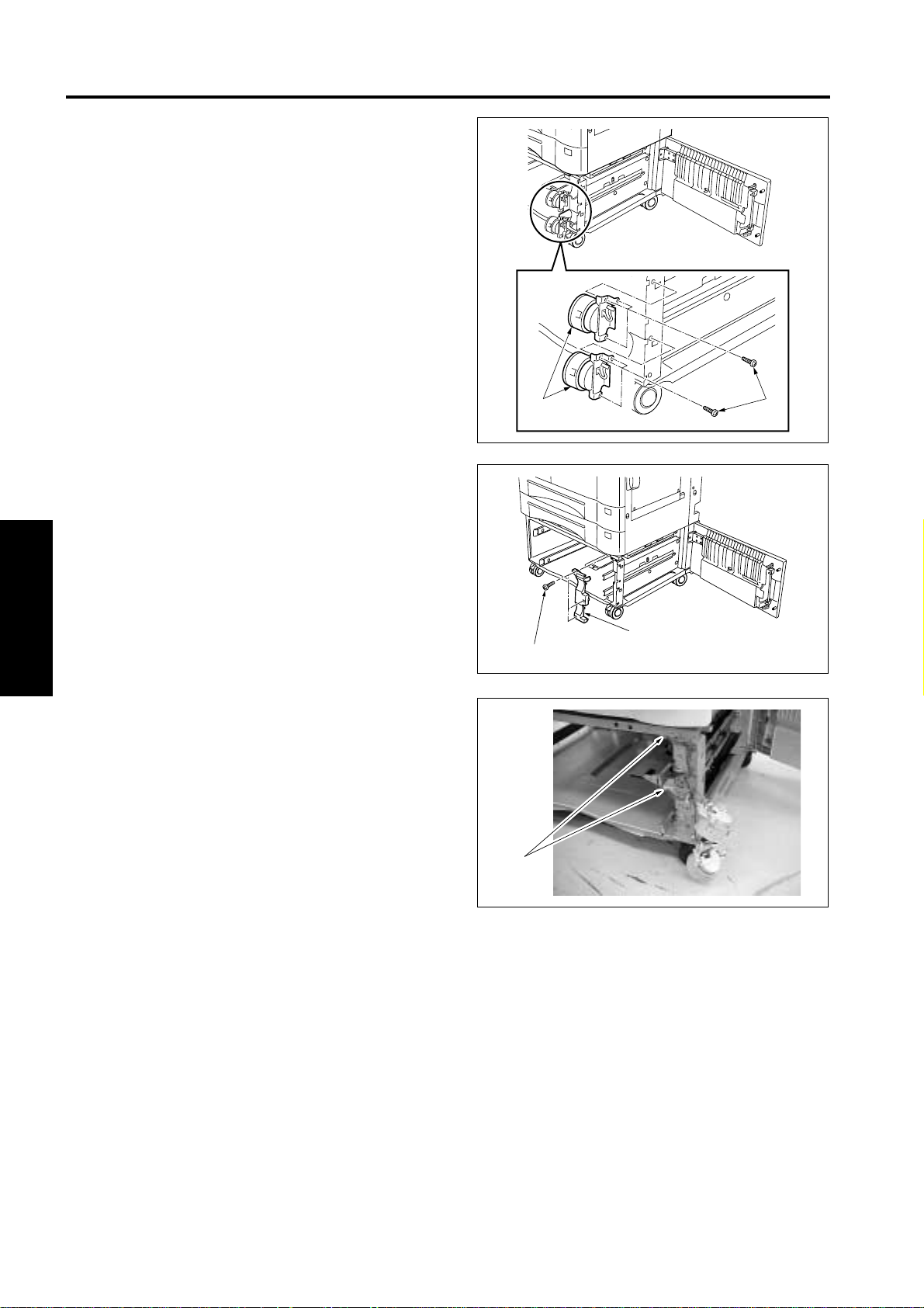
1. Remove the lock tapes inside the tray.
(DB-211: Upper and lower trays)
Lock tape
Remove the locking part (2 screws) and lock
tapes inside the tray.
(DB-411: LCT)
Locking part
Lock tape
[2] Installing the main body
Caution:
• When placing the main body on the drawer
base unit, be sure to lift it by holding both sides
as shown below. (Draw two carrying handles
on the right side.)
• Be sure to have two or more personnel work
together for installing the main body.
Heed the above cautions to avoid suffering injuries to your fingers.
Caution:
Before carrying the machine, attach two stopper
covers included in the accessory parts of the main
body to the carrying handles as illustrated below.
2. Return each tray to its original position.
Stopper covers
1. Fit the front fixing cover.
Front fixing cover
E-2
Page 55

2. Place the main body onto the drawer base unit,
aligning the two guide pins on the rear side of the
drawer base unit.
Caution:
Be careful not to catch the connector wire of the
drawer base unit in between the main body and
the drawer base unit.
6. Remove the connector cover of the main body,
then connect the two connectors of the drawer
base unit to the main body.
Connectors
7. Fix the connector cover (included in accessories)
with a screw.
Connector cover
Guide pins
3. Confirm that the right side door of the main body
is flush with the right side cover of the drawer
base unit.
4. Check that the casters of the drawer base unit
touch securely on the floor.
For DB-211, perform the following steps 5 to 8.
For DB-411, perform the following steps 5 to 7.
5. Open the right side cover of the drawer base unit,
then fix the accessory guide part. (1 screw)
Fixing screw
Screw
8. Put the paper size label. (DB-211 only)
(1) Put the paper size label around the paper size
indication dial, aligning the top edge of the
label with the groove on the dial.
Groove
Guide part
Paper size label
E-3
Page 56

(2) Set the dial at the paper size to be loaded in
the tray.
[3] Locking the casters
Lower the lock lever of each caster. (Two at the
front)
<Changing the position of the front/rear paper guide
plates>
1. Remove the reinforcing plate. (2 screw)
2. Remove two screw fixing the front paper guide,
then remove it from the LCT bottom plate.
3. Place the front paper guide at the position of the
paper size to be used by referring to the size indicator, then fix it with the two screws.
4. Reinstall the reinforcing plate.
5. Repeat the same procedure for resetting the rear
paper guide.
<Changing the position of the rear stopper>
6. Remove the rear stopper, holding it by the center
of the inside. Referring to the paper size marked
on the tray up-down plate of the LCT, set the rear
stopper at the position of the paper size required.
Caution:
When loading inch-sized paper, use the rear stopper (small) included in accessories.
A4
8 5x11
B5
8 5x11R
A4R
B5R
Lock lever
[4] Setting the paper size (DB-411 only)
The LCT has initially been set to accept A4 paper.
Follow the procedure below to change the paper
size setting inside the LCT.
Change the fixing positions of the front and rear
paper guides and rear stopper to fit the paper size to
be used.
Rear stopper
Reinforcing plate
Rear paper guide
A4R
8 5x11R
B5R
8 5x11A4B5
B5R
A4R
8 5x11R
B5
8 5x11
A4
7. Set the paper size indication dial at the paper
size to be loaded in the tray.
Front paper guide
E-4
 Loading...