

Page 1

Spectrophotometer
CM-26dG
CM-26d
CM-25d
En
Basic Operating
Instructions
Please read before using the instrument.
This manual explains the basic procedures for measuring
color and/or gloss with the CM-26dG / 26d / 25d
spectrophotometers.
Note) For setting and operation details, see the instruction
manual of the CM-26dG / 26d / 25d.
Page 2

Table of Contents
Names of Parts ..................................................... 1
Measurement ....................................................... 5
When color difference is measured ....................... 9
Setting measurement conditions ........................ 16
How to set the measuring instrument ................. 17
Page 3

Names of Parts
■ Instrument
Viewfinder
(Specimen
confirmation
window)
Viewfinder
Measurement button
(It is on the left and right)
Sample
surface
aperture
Viewfinder lever
LCD screen
Control panel
Charging lamp
Measurement
area switch
Power switch
USB connection
terminal
(Mi ni- B ty pe)
Wrist strap
attachment hole
(CM-26dG/26d only)
Screw holes for securing
Battery
cover
1
Page 4
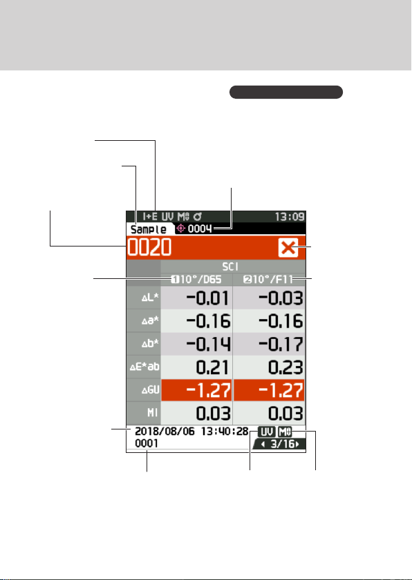
Names of Parts
■ Display (LCD Screen)
P.22, Instruction Manual
Status bar
Target/Sample
Data number and
name
Observer/
Illuminant 1
Measurement
date/time
Target reference (sample) /
Affiliated group (target)
Target to be used for association
with the next measurement or
filter (target)
Pass/fail
result
Observer/
Illuminant 2
UV setting
Measurement
area
2
Page 5
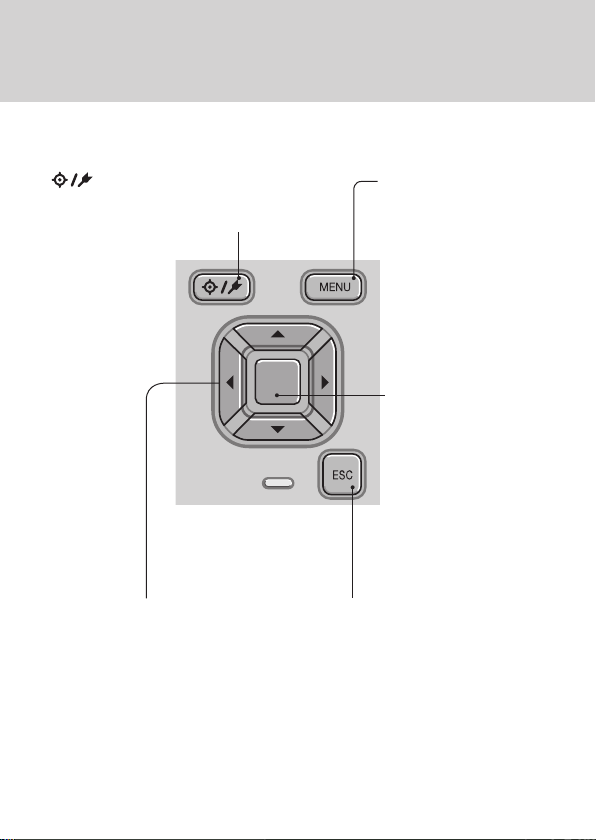
■ Operation Keys
[ ]
Switches between <Target> screen
and <Sample> screen.
[◀, ▶, ▲, ▼] keys
Switches screen tabs from the
<Results Display> screen,
moves the cursor on the
<Settings> screen, or changes
the selected value.
(Target/Sample) key
[MENU] key
Displays the
<Settings> screen.
[Confirmation] key
Sets the item or
setting indicated
by the cursor on
the various setting
screens. This key
also switches to
detail screens for
data selected in the
list displayed on the
<Results Display>
screen.
[ESC] key
Returns to the previous
screen without configuring
the settings when pressed
on the <Settings> screen,
and returns to list screen
when pressed on the sample
details screen.
3
Page 6

■Calibration
Stage
CM-26dG
CM-26d
CM-25d
Cap
Zero calibration hole
White calibration plate
Gloss calibration plate
Cap
Zero calibration hole
White calibration plate
Target mask holder
Cap
Zero calibration hole
White calibration plate
4
Page 7

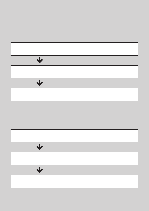
Measurement
Turning the Power ON
1
Language selection
P.103, Instruction Manual
Measurement cond. setting
Measurement area selection
P.33, Instruction Manual
Note: Make sure the measurement area set on the instrument
is the same as the area of the target mask to be used.
Zero calibration
P.35, Instruction Manual
White calibration
2
White calibration
Gloss calibration (* CM-26dG only)
* As necessary (after initialization, etc.)
P.92, Instruction Manual
* When required depending on the
measurement conditions
* Only when required (when changing
the measurement conditions, etc.)
(P. 6)
(P. 6, P.7)
Measurement
3
(P. 8)
5
Page 8

1
Turning the
Power ON
P. 32,
Instruction Manual
Press and hold the power switch for about 1 second.
①
∙ When first turning the instrument ON after purchasing,
the language setting screen will be displayed, followed
by the date and time setting screen. Configure the
settings according to P.103 and P.104.
2
White
calibration
P. 37,
Instruction Manual
To perform white calibration
Note:
Zero calibration must be performed before white calibration
if there have been significant changes in the measurement
environment, if the instrument has not been used for a long
period of time or if using the MAV target mask (with glass).
Select “Calibration (Excluding
①
Zero Cal.)” and press the
[Confirmation] key.
Place the instrument on
②
the calibration stage.
Place the
instrument
on the
calibration
stage
Calibration stage
Press the measurement button.
③
∙ White calibration will be performed.
∙ Do not move the instrument until white
calibration is complete.
according to
the marks.
6
Page 9

Measurement
Gloss
calibration
only with the 26dG
P. 38,
Instruction Manual
④
⑤
If using the CM-26dG, perform
gloss calibration next.
Place the instrument
in the gloss calibration
position.
Place the
instrument
on the
calibration
stage
Calibration stage
Press the
measurement button.
∙ Gloss calibration will
be performed.
∙ Do not move the
instrument until gloss
calibration is complete.
∙ When gloss calibration is
completed, the screen returns
to the <Sample> screen.
according to
the marks.
7
Page 10

3
Measurement
P. 41,
Instruction Manual
Measurement
Check the Sample
①
screen.
If not displayed, switch to the
・
Sample screen.
<Reference
color scre en>
Set the specimen
②
<measurement
screen>
measuring port on the
sample to measure.
∙ Take care to prevent floating
or tilting from occurring.
Press the
③
measurement button.
∙ The results are displayed on
the screen. The sample was
saved as "0001".
8
Page 11
When color difference is measured
<Measuring color difference in the
normal mode>
Color difference target settings
1
Pass/fail judgment criteria settings
2
Measurement
3
<Measuring color difference in the
simple mode>
Set to "Simple mode".
1
Measuring a target
2
Measuring a sample
3
(P.13)
(P.14)
(P.15)
(P.15)
(P.10)
(P.11)
9
Page 12

<Measuring color difference in the normal mode>
1
Color
difference
target
settings
P. 41,
Instruction Manual
Setting color difference by
measuring a target
Display the target or
①
target list screen.
∙ Set the target number with
the [] and [] keys before
imparting measurement.
Set the specimen
②
measuring port on the
sample to measure.
∙ Take care to prevent floating
or tilting from occurring.
Press the
③
measurement button.
∙ The results are displayed on the
screen.
∙ The selected number is used
as the target data number. If
data already exists under that
number, the instrument asks
whether to overwrite that data or
not, therefore enter the target by
pressing the [Confirmation] key.
The target is set.
10
Page 13

2
Pass/fail
judgment
criteria
settings
P. 58 -5 9,
Instruction Manual
When color difference is measured
Select <Target Menu>
①
- <Pass/Fail> - "Edit
tolerance".
Input settings.
②
Settings
○ x / y : -0.2000 to 0.2000
○ Equation / MI : 0.00 to 20.00
○ Other than the above : -20.00 to 20.00
11
Page 14

Once settings have
③
been completed, select
"OK" to establish
them.
Close the
④
"Edit tolerance" screen.
12
Page 15

3
Measurement
P. 41,
Instruction Manual
When color difference is measured
Display the Sample
①
screen.
∙ Select a target number before
imparting measurement.
Set the specimen
②
measuring port on the
sample to measure.
∙ Take care to prevent floating
or tilting from occurring.
Press the
③
measurement button.
∙ The results are displayed on the
screen.
∙ A sample number is
automatically assigned in the
order of measurement.
Mark signif ying a “Pass” judgm ent
13
Page 16

<Measuring color difference in the simple mode>
Press the [ESC] button
①
1
Set to
“Simple
to skip the calibration
prompt displayed
immediately after
turning the power ON.
mode”.
P.48,
Instruction Manual
Select "Yes" when
②
"Change to the simple
mode?" appears on the
display.
O r,
Select <Settings> -
①
<Instrument Mode> "Simple".
14
Page 17

②
①
2
Measuring a
target:
Absolute value
measurement
P.48,
Instruction Manual
①
3
Measuring a
sample:
Difference
measurement
P.48,
Instruction Manual
Press the [Target/Sample] button or
[ESC] button to switch to the simple
measurement screen.
or
Press the
measurement button.
Press the
measurement button.
Notes
Measurement data is not
・
saved in the simple mode.
The opacity mode cannot
・
be selected while the
instrument is in the simple
mode. Moreover, the
simple mode cannot be
engaged while the opacity
mode is active.
15
Page 18
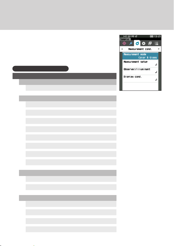
Setting measurement conditions
Measurement conditions (Measurement mode,
SMT Times, Observer/Illuminant, Display) must
be set before impar ting measurement.
The menu items that can be set are as follows.
P.80 - 100, Instruc tion Manual
Measurement cond.
Measurement mode
Color & Glos s / Color only / Gloss only / O pacity
Measurement setup
Specular component
UV
Auto average
Manual average
Manual average option (SMC average option)
SMC
SMC Threshold
SMC Times
Observer/Illuminant
Observer/Illuminant 1
Observer/Illuminant 2
Display cond.
Display type
Color space
Color dierence equation
Custom 01 to 14
16
Page 19

How to set the measuring instrument
To set measurement instrument options, select
“Instrument setup” from the <Setting> screen.
The menu items that can be set are as follows.
P.101 - 110, Instruc tion Manual
Instrument setup
User type
Language
Date format
Date & time
Brightness
Direction
Beep
Auto power o
Password setting
17
Page 20

2019 KONICA MINOLTA, INC.
©
Use this QR code
to download this
manual in pdf
form.
En
9222-AC5J-41
BJCAKK
 Loading...