

Page 1

Spectrophotometer
CM-2600d/2500d
E
Instruction Manual
Es
Manual de instrucciones
Page 2
Safety Symbols
The following symbols are used in this manual to prevent accidents which may occur as result of incorrect use of the instrument.
Denotes a sentence regarding a safety warning or note.
Read the sentence carefully to ensure safe and correct use.
Denotes a prohibited operation.
The operation must never been performed.
Denotes an instruction.
The instruction must be strictly adhered to.
Denotes a prohibited operation.
Never disassemble the instrument.
Denotes an instruction.
Disconnect the AC power cord from the AC outlet.
Notes on this Manual
• Copying or reproduction of all or any part of the contents of this manual without KONICA MINOLTA
SENSING’s permission is strictly prohibited.
• The contents of this manual are subject to change without prior notice.
• Every effort has been made in the preparation of this manual to ensure the accuracy of its contents.
However, should you have any questions or find any errors, please contact a KONICA MINOLTA
SENSING -authorized service facility.
• KONICA MINOLTA SENSING will not accept any responsibility for consequences arising from the
use of the instrument.
Page 3
Safety Precautions
To ensure correct use of this instrument, read the following points carefully and adhere to them. After
you have read this manual, keep it in a safe place where it can be referred to anytime a question arises.
WARNING
Do not use the instrument in places
where flammable or combustible gases
(gasoline etc.) are present. Doing so
may cause a fire.
Always use the AC adapter supplied as
a standard accessory or the optional AC
adapter, and connect it to an AC outlet
of the rated voltage and frequency.
AC adapters other than those specified
by KONICA MINOLTA SENSING,
this may result in damage to the unit,
fire or electric shock
If the instrument will not be used for a
long time, disconnect the AC adapter
from the AC outlet. Accumulated dirt or
water on the prongs of the AC adapter’s
plug may cause a fire and should be re
moved.
Take special care not to allow liquid or
metal objects to enter the instrument.
Doing so may cause a fire or electric
shock. Should liquid or metal objects
enter the instrument, turn the power
OFF immediately, disconnect the AC
adapter from the AC outlet (or remove
the batteries if they are used), and con
tact the nearest KONICA MINOLTA
SENSING-authorized service facility.
(Failure to adhere to the following points may result
in death or serious injury.)
If the
-
-
Do not disassemble or modify the instrument or the AC adapter. Doing so
may cause a fire or electric shock.
The instrument should not be operated if
it is damaged or AC adapter is damaged,
or if smoke or odd smells occur. Doing
so may result in a fire. In such situations,
turn the power OFF immediately, dis
connect the AC adapter from the AC
outlet (or remove the batteries if they are
used) and contact the nearest KONICA
MINOLTA SENSING-authorized serv
ice facility.
Do not insert or disconnect the AC
adapter with wet hands. Doing so may
cause electric shock.
Do not dispose of batteries in fire, short
their terminals, apply heat to them, or
disassemble them. Also, do not recharge
them (if they are not chargeable). Doing
so may cause explosion or heat genera
tion, resulting in fire or injury.
-
-
-
CAUTION
Do not perform measurement which the
measurement aperture directed towards
your face. Doing so may damage them.
Do not use batteries other than those
specified by KONICA MINOLTA
SENSING.
When installing batteries in the instrument, make sure that they are correctly
oriented according to the (+) and (–)
marks. Failure to adhere to these in
structions may cause batteries to explode or leakage of electrolyte, resulting
in fire, injury or air pollution.
(Falling to adhere to the following points may result in
injury or damage to the instrument or other property.)
-
Do not place the instrument on an unstable or sloping surface. Doing so may result in its dropping or overturning,
causing injury. Take care not to drop the
instrument when carrying it.
When using the AC adapter, make sure
that the AC outlet is located near the in
strument and that the AC adapter can be
connected to and disconnected from the
AC outlet easily.
-
E-1
Page 4

Notes on Use
<Operating Environment>
• This instrument and the AC adapter supplied as a standard accessory have been designed exclusively
for indoor use.
• Do not leave the CM-2600d/2500d in direct sunlight or near sources of heat, such as stoves etc. The
internal temperature of the instrument may become much higher than the ambient temperature in such
cases.
• Do not use the CM-2600d/2500d in areas where dust, cigarette smoke or chemical gases are present.
Doing so may cause deterioration in performance or breakdown.
• Do not use the CM-2600d/2500d near equipment which produces a strong magnetic field (such as
speakers etc.)
• The CM-2600d/2500d belongs to installation category II products (equipment which is powered by an
AC adapter connected to a commercially available power).
• The CM-2600d/2500d belongs to pollution level 2 products (equipment which may cause temporary
electrical hazards due to contamination or condensation or products which are used in such an envi
ronment).
• Do not use the CM-2600d/2500d at altitudes of higher than 2000m.
• Use this instrument at ambient temperature between 5 and 40°C and relative humidity 80% or less (at
35°C) with no condensation
range may unsatisfy its original performance.
*1 Operating temperature/humidity range of products for North America: between 5 and 40°C and relative humid-
ity 80% or less (at 31°C) with no condensation
<Measurement>
• When using the instrument upside-down, make sure no dirt or dust get into the aperture.
• When using the instrument for long periods of time, the displayed value may change depending on
changes in the environment. Therefore, in order to achieve accurate measurements, we recommend
that white calibration be done regularly using the White Calibration Plate.
<White Calibration Plate>
• The calibration data for the White Calibration Plate was measured at 23°C. To achieve the highest accuracy when measuring absolute values (colorimetric values), calibration and measurement should be
performed at 23°C.
• Do not allow the White Calibration Plate to get scratched or stained.
• If you are not going to use the White Calibration Plate, attach the cap to the White Calibration Plate to
prevent entry of ambient light.
<Target Mask>
• Do not touch the Target Mask’s inner surface by hand, scratch it or make it dirty.
• When the Target Mask is not in use, install it on the White Calibration Plate (CM-A145) to prevent
exposure to external light.
<Measuring Base>
• When removing the “Measuring Base”, make sure that the screws used to attach the base to the instrument are stored properly and are not mislaid. If the screws do become mislaid, use M3 cross-headed
screws that are 4 to 5 mm long as replacements. (For details, see page E-16.)
• Do not tighten the screws too tightly when attaching the “Measuring Base”. This could damage the
“Measuring Base” or the instrument itself.
• Remove the “Measuring Base” before using the optional Zero Calibration Box or Dust Cover Set.
<Power Source>
• Make sure that the power switch is set to OFF (“O”) when the CM-2600d/2500d is not in use.
• Always use the AC adaptor (AC-A17) supplied as a standard accessory and connect it to an AC outlet
of the rated voltage and frequency. Use the AC power supply voltage of the rated supply voltage (with
in ± 10%).
(*1)
. Operating this instrument outside specified temperature and humidity
-
-
E-2
Page 5

<System>
• Do not subject the CM-2600d/2500d to strong impact or vibration. Doing so may cause deterioration
in performance or breakdown.
• Since the specimen measuring port and integrating sphere are extremely precise optical components,
great care should be taken to prevent them getting dirty or exposing them to impact. If you are not go
ing to use the CM-2600d/2500d, put it on the White Calibration Plate (CM-A145).
• The CM-2600d/2500d may cause interference if used near a television, radio, etc.
• Since the CM-2600d/2500d uses a microcomputer, the LCD may go blank if it is exposed to strong
static electricity. In this case, turn the power OFF, then turn it ON again. If black smudges appear on
the LCD, wait until they disappear naturally.
• When turning the power OFF and then ON again, wait several seconds after turning the power OFF.
<Backup Battery>
• Measured data and various settings are stored in the memory backed up by batteries. The backup batteries are automatically charged during operation of this instrument, and can retain the contents of the
memory for 4.5 months if they have been fully charged. At the time of purchase, the backup battery
may not be fully charged. To charge the backup battery, set the power switch to ON. Charging of the
backup battery is performed continuously while the instrument is switched on, even while the instru
ment is being used. Full charging is completed in 25 hours, and there is no danger of overcharging.
• It is recommended to keep a backup of your important data in another recording medium using optional
Color Data Software (sold separately).
Note
• The backup batteries’ model number is VL2020 (3V).
• Do not try to replace the backup batteries by yourself. Contact a KONICA MINOLTA SENSING-authorised
service facility.
-
-
Notes on Storage
• The CM-2600d/2500d should be stored at temperatures between 0°C and 45°C, and at a relative humidity of 80% or less (35°C), without condensation. Do not store the instrument in areas subject to
high temperatures, high humidity, sudden changes in temperature, or where freezing or condensation
may occur, because these circumstances may cause breakdown. It is more reliable to store the CM2600d/2500d with a drying agent (such as silica gel) at a temperature around 20°C.
• Do not leave the CM-2600d/2500d inside a car such as in the cab or trunk. Otherwise, the temperature
and/or humidity may go leave the allowable range for storage during midsummer or midwinter, result
ing in breakdown.
• Keep the packing materials used for shipment and use it to transport the CM-2600d/2500d. This protects the instrument from sudden changes in temperature, vibration, and shock.
• Do not store the CM-2600d/2500d in areas where dust, cigarette smoke or chemical gases are present.
Doing so may cause deterioration in performance or breakdown.
• Entry of dust into the measuring aperture will hinder accurate measurement. Block the measuring port
to prevent entry of the dust.
• The White Calibration Plate may become discolored if left exposed to light. Therefore, make sure that
the lid is closed to prevent entry of ambient light when it is not in use.
• The Target Masks may discolor if they are left exposed to light. When they are not in use, keep them
in a safe place to prevent exposure to light and to protect them from scratches and dust.
• Be sure to keep all packing materials (cardboard box, cushioning material, plastic bags, etc.). They can
be used to protect the instrument during transportation to service facility for maintenance (re-calibra
tion etc.).
• If you are not going to use the CM-2600d/2500d for more than two weeks, the batteries must be removed. If the batteries are left in the instrument, leakage may occur resulting in damage to the instrument.
-
-
E-3
Page 6

Notes on Cleaning
• If the CM-2600d/2500d becomes dirty, wipe it with a soft, clean dry cloth. Never use solvents such as
thinner and benzene.
• If the White Calibration Plate becomes dirty, wipe it gently with a soft, clean dry cloth. If dirt is difficult to remove, contact the nearest service facility listed on the attached sheet.
• If the inner surface of the Target Masks or the inside of the integrating sphere get dirty, contact a
KONICA MINOLTA SENSING-authorized service facility.
• Should the CM-2600d/2500d break down, do not try to disassemble and repair it by yourself. Contact
a KONICA MINOLTA SENSING-authorized service facility.
E-4
Page 7
Contents
Safety Precautions .......................................................................................................................... E-1
Notes on Use............................................................................................................................... E-2
Notes on Storage......................................................................................................................... E-3
Notes on Cleaning....................................................................................................................... E-4
Conventions ................................................................................................................................ E-8
Chapter 1 Before Using the Instrument
Accessories....................................................................................................................................... E-10
Standard Accessories .................................................................................................................. E-10
Optional Accessories .................................................................................................................. E-11
Names and Functions of Parts....................................................................................................... E-12
Preparation ..................................................................................................................................... E-14
Attaching/Removing a Target Mask........................................................................................... E-14
Attaching/Removing the “Measuring Base”.............................................................................. E-16
Cleaning Each Part...................................................................................................................... E-17
Inserting the Batteries ................................................................................................................. E-18
Connecting the AC Adapter........................................................................................................ E-19
Turning Power ON...................................................................................................................... E-20
Turning Power OFF .................................................................................................................... E-20
System Configuration..................................................................................................................... E-21
Items You Must Know ................................................................................................................... E-22
Language Mode .......................................................................................................................... E-22
Measurement Mode .................................................................................................................... E-22
Target Modes .............................................................................................................................. E-23
Screen Display ............................................................................................................................ E-23
Battery Alarm ............................................................................................................................. E-23
Data Saving................................................................................................................................. E-23
Chapter 2 Preparation for Measurement
Flow of Measurement ................................................................................................................. E-26
Turning Power On for the First Time .......................................................................................... E-27
Setting the Language Mode and Measurement Mode ................................................................ E-27
Selecting the Target Mode.......................................................................................................... E-28
Initial Setting................................................................................................................................... E-29
Setting the Date and Time .......................................................................................................... E-30
Setting the Display Direction...................................................................................................... E-31
Setting the LCD Contrast............................................................................................................ E-32
Selecting a Measurement Condition............................................................................................. E-33
Setting a Measurement Condition ................................................................................................ E-34
Setting the Measurement Area and Specular Component Mode................................................ E-35
Setting the UV ............................................................................................................................ E-36
Selecting Illuminant 1................................................................................................................. E-36
Selecting Illuminant 2................................................................................................................. E-37
Selecting the Observer................................................................................................................ E-37
Selecting the Display Mode........................................................................................................ E-38
Selecting a Color Space .............................................................................................................. E-39
Setting the Number of Measurements for Manual Averaging.................................................... E-40
Setting the Standard Deviation for Manual Averaging .............................................................. E-40
E-5
Page 8

Contents
Setting the Number of Measurements for Auto Averaging........................................................ E-40
Setting the Delay Time ............................................................................................................... E-41
Zero Calibration ............................................................................................................................. E-44
White Calibration........................................................................................................................... E-46
Setting a Color Difference Target Data........................................................................................ E-48
Selecting a Color Difference Target Data .................................................................................... E-50
Deleting a Color Difference Target Data.................................................................................... E-51
Setting Color Difference Tolerances............................................................................................. E-52
Box Tolerance............................................................................................................................. E-52
Elliptical Tolerance..................................................................................................................... E-55
Chapter 3 Measurement
Measurement................................................................................................................................... E-64
Displaying the Measurement Results............................................................................................ E-66
Measured Data ............................................................................................................................ E-66
Pass/Fail Judgment ..................................................................................................................... E-67
Color Difference Graph .............................................................................................................. E-68
Spectral Reflectance Graph ........................................................................................................ E-69
Assessments................................................................................................................................ E-70
Switching the Display Contents of the Measurement Results.................................................... E-72
Deleting Measured Data ............................................................................................................. E-74
Abbreviations on LCD Display .................................................................................................. E-76
Measurement Results for “linked to each data.”......................................................................... E-77
Chapter 4 Other Functions
Measuring the Average .................................................................................................................. E-80
Manual Averaging ...................................................................................................................... E-80
Auto Averaging........................................................................................................................... E-82
Pass/Fail Judgment for Color Difference ..................................................................................... E-83
Pass/Fail Judgment Based on Box Tolerances ........................................................................... E-83
Pass/Fail Judgment Based on Elliptical Tolerances ................................................................... E-85
Assessments ..................................................................................................................................... E-87
Assessment by Box Tolerances .................................................................................................. E-87
Assessment by Elliptical Tolerances .......................................................................................... E-89
Connecting to an External Device................................................................................................. E-92
Connecting a Personal Computer ............................................................................................... E-92
Outputting to a Printer ................................................................................................................ E-95
TASK Mode .................................................................................................................................... E-101
What is TASK Mode?................................................................................................................. E-101
Downloading a Task ................................................................................................................... E-101
Performing Measurement in TASK Mode.................................................................................. E-102
Chapter 5 Troubleshooting
Error Messages ............................................................................................................................... E-110
Troubleshooting.............................................................................................................................. E-112
Chapter 6 Appendix
Principles of Measurement ............................................................................................................ E-116
Illuminating/Viewing System..................................................................................................... E-116
Illumination Area and Measurement Area.................................................................................. E-117
Simultaneous SCI/SCE Measurement ........................................................................................ E-118
E-6
Page 9

Contents
UV Control ................................................................................................................................. E-118
Target Mode.................................................................................................................................... E-119
Relation Between Measured Data and Target Color .................................................................. E-119
Deleting a Color Difference Target Data.................................................................................... E-119
Notes on Changing the Target Mode.......................................................................................... E-119
Specifications................................................................................................................................... E-123
Dimensions ...................................................................................................................................... E-125
Menu Structure............................................................................................................................... E-126
Reading the menu structure diagram .......................................................................................... E-126
Menu Structure diagram ............................................................................................................. E-127
E-7
Page 10
Contents
Conventions
This manual describes how to setup the CM-2600d/2500d which the firmware version is 1.40 or higher
and use it to take measurements.
• Organization
The CM-2600d/2500d (Ver. 1.30 or higher) supports two types of the target mode, “linked to each data.”
and “defined in COND.”; the procedure and details for these types varies slightly.
This manual describes the procedures for the default target mode, which is “linked to each data.”. It only
includes information for the “defined in COND.” mode where it differs from the default.
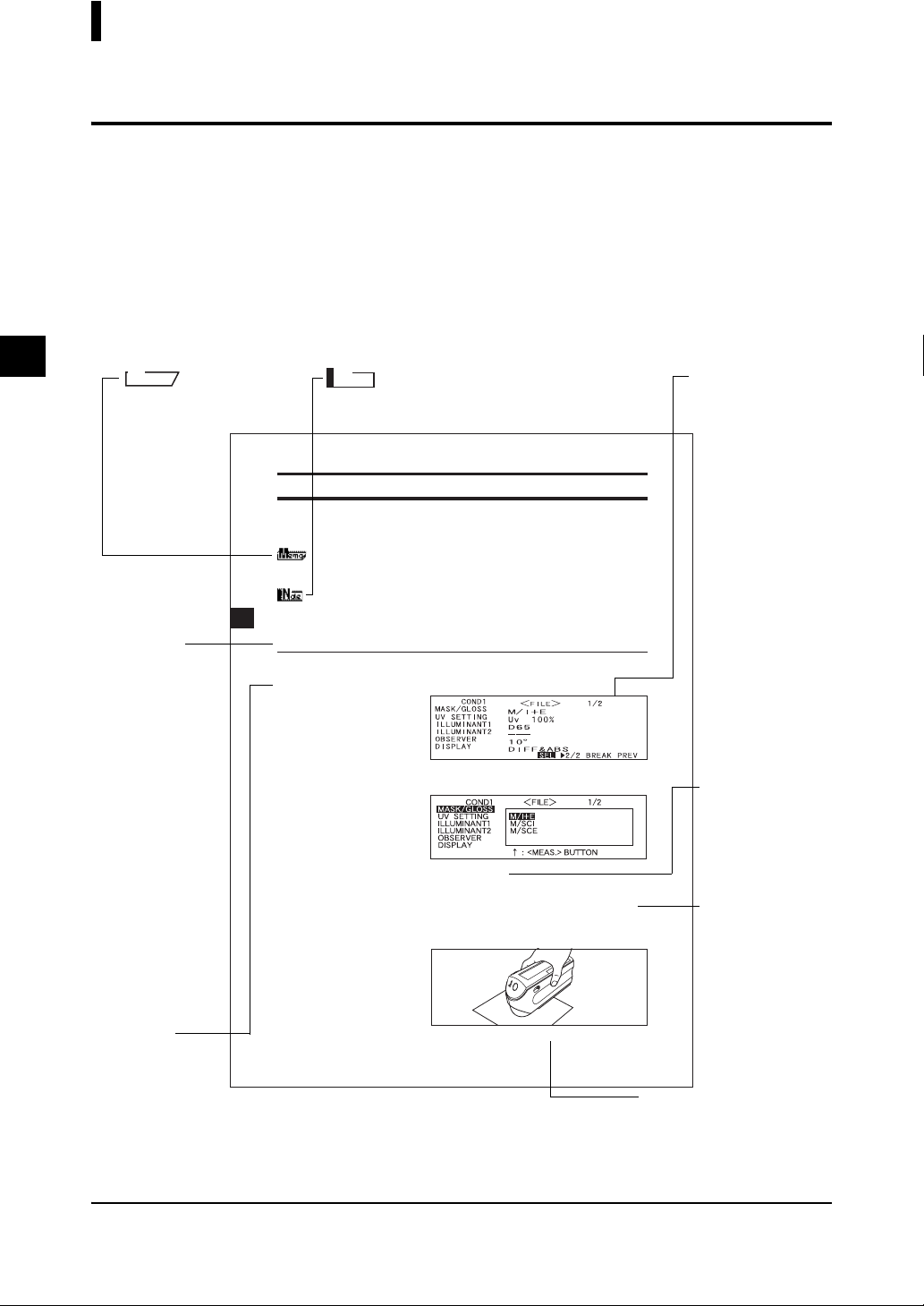
• Page layout
Symbols used in this manual are explained below.
*Note that the page shown in the illustration is for explanatory purposes only, and is not an actual page
from this manual.
M
emo
Gives useful Information and additional explanations.
Note
Gives the points that you should know to perform operations correctly. Make sure that you read the notes.
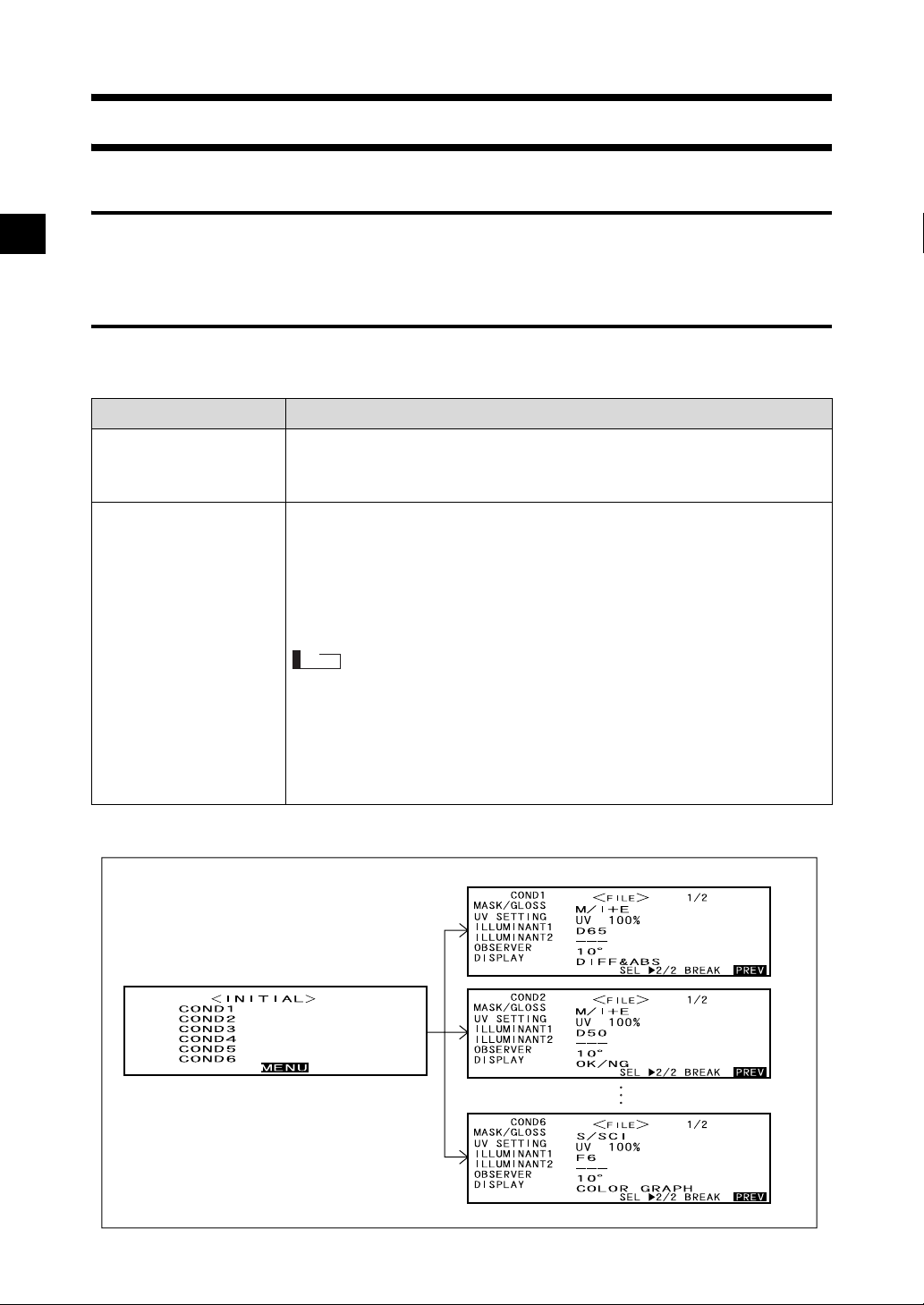
Setting an Environmental Condition
Up to six sets of conditions (COND 1 to COND 6) can be set. Since the instrument will perform measurement according to the selected condition, conditions must be set prior to start of measurement.
The following nine condition items can be set:
Screen
Shows the contents of the screen
in effect when the
given operation is
carried out.
• A setting can be made for the currently highlighted item. To confirm the setting, press AA. The next item will
be highlighted automatically.
• The items (1) to (9) must be set in this order. If incorrect settings have been made, you must start once again
from item (1).
Start screen
Shows the screen
from which operation must be
[Setting Procedure]
<FILE> screen
Turn BB to select “SEL”, then press AA.
1
started.
• “SEL” can be selected in page 1/2 only.
Turn BB to select the desired setting, then press AA.
2
<Settings>
• M/I+E: ø8 mm, simultaneous measurement of SCI and SCE
• M/SCI: ø8 mm, SCI
• M/SCE: ø8 mm, SCE
• The measurement area that suits the target mask used for measurement or the setting of the lens position selector switch must be selected.
Direct the specimen measuring port to the specimen.
3
Procedure
Shows the oper-
• If necessary, slide the viewfinder lever to check the position of the specimen.
60
ating procedure.
C............ Indicates the <MEAS.> button.
B....... Indicates request to turn the navigation wheel to the right or left.
A....... Indicates request to press the navigation wheel.
Settings
Gives the range
and explanation
of the values to
be set in this
screen.
TIP (screen)
Gives explanation
about the screen
and operations that
can be carried out
from this screen.
Screen note
Gives the points to note on
the operations to be performed from this screen.
For the version of the instrument firmware
The version of the instrument firmware can be confirmed on the screen which is displayed first after
switching power on.
E-8
Page 11

Chapter 1
Before Using the Instrument
E-9
Page 12
Accessories
Standard and optional accessories are available with the instrument.
Standard Accessories
Make sure that all the following items are present.
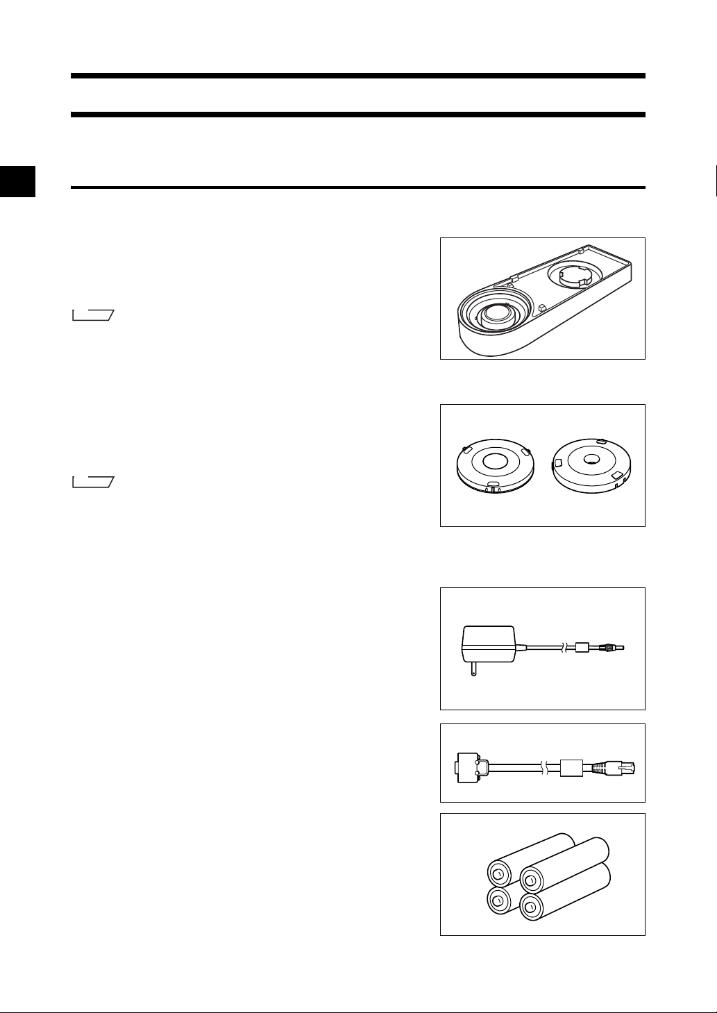
White Calibration Plate CM-A145
Used to perform white calibration.
A data disk containing white calibration data is supplied with
this accessory.
M
emo
• This accessory can be used as a table on which to store the CM-2600d/
2500d.
• In the case of the CM-2600d, a Target Mask that is not in use can be
stored on this accessory.
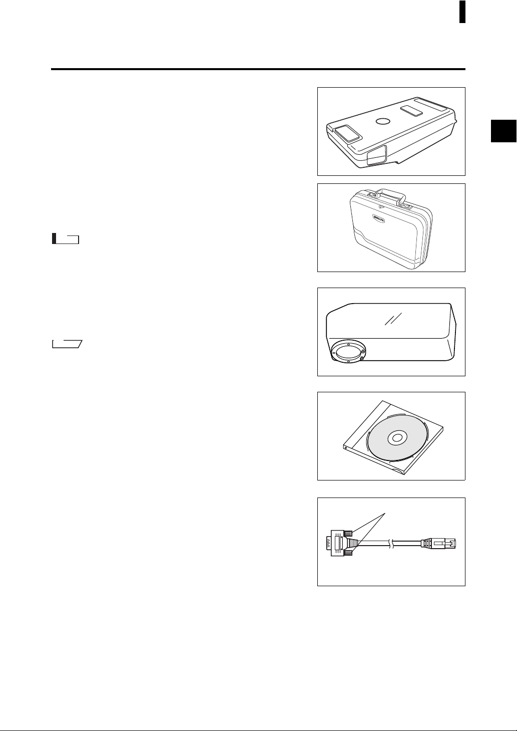
Target Mask
CM-A146 (for ø8 mm) CM-A147 (for ø3 mm)
Used to switch the illumination area (specimen measuring port
area) according to the specimen.
M
emo
• CM-A146 (for ø8 mm) is already attached to the CM-2600d/2500d
when it is supplied.
• CM-A147 (for ø3 mm) can be used for the CM-2600d only, and it is
already attached to the White Calibration Plate (CM-A145) when it is
supplied.
AC Adapter AC-A17
Used to supply power from an AC outlet to the instrument.
Input: Voltage 100 to 240 VAC (50-60 Hz)
Output: Voltage 5 VDC Current 2.8 A (Max.)
RS-232C Cable IF-A16
(for IBM PC/AT, 9-pin, 2 m)
Used to connect the instrument to a personal computer (PC).
AA-size battery (× 4)
E-10
Page 13
Optional Accessories
Zero Calibration Box (CM-A32)
Used to perform zero calibration.
Hard Case (CM-A148)
Can be used for storing the CM-2600d/2500d, the instruction
manual and standard accessories, such as the White Calibration
Plate and AC adapter.
Note
The Hard Case is designed purely for storing the above items and
must not be used for transportation purposes.
Dust Cover Set (CM-A149)
Used when measuring powder or wet surfaces.
It can also be used when woven fabric needs to be laid flat and
measured.
Accessories
M
emo
The Dust Cover (CM-A152) can be used as a vinyl cover for the replacement.
Color Data Software “SpectraMagic NX” (CM-S100w)
This software supports the two types of the target-mode,
“linked to each data.” and “defined in COND.”, provided by
this instrument. It allows you to operate the instrument from
your PC, and to process data and manage files.
Printer Cable (CR-A75)
Used to transfer data to a printer. Connect a printer to the external output terminal on the instrument with this cable. The Dsub connector (9-pin) of the cable must be connected to the
printer.
*metric screw type
E-11
Page 14
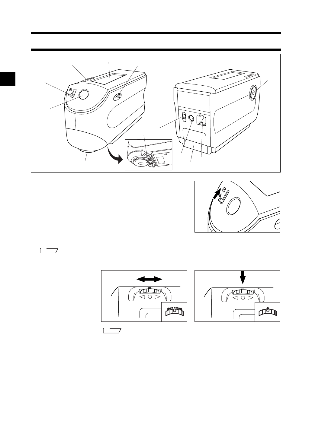
Names and Functions of Parts
3
4
6
2
MAV
SAV
1
A
B
5
1 Viewfinder
Used to check the position of the specimen. By sliding the
lever you can check whether the specimen is set correctly.
2 Viewfinder lever
Used to open/close the viewfinder. By sliding the lever in
the direction of the arrow, the white LED will light up and
illuminate the specimen, so the specimen can be seen
through the viewfinder to check that it is set correctly.
0
7
I
O
8
9
Open
M
emo
The specimen cannot be measured if the viewfinder is open and the white LED is lit.
3 Navigation wheel
Use this navigation
wheel to select an
item or set the select
ed item.
To select an item, turn
it to the right or left
until the desired item
is shown. To set the
selected item, press it.
4 LCD display
Displays the setting items and measured data.
5 Specimen measuring port
A port provided to measure the specimen.
With the CM-2600d, a Target Mask must be attached to this port, according to the measurement area
selector position.
E-12
To select To enter
-
M
emo
When selecting an item or setting a value, holding down the jog dial will switch
the item or value from one to another continuously.
Page 15
Names and Functions of Parts
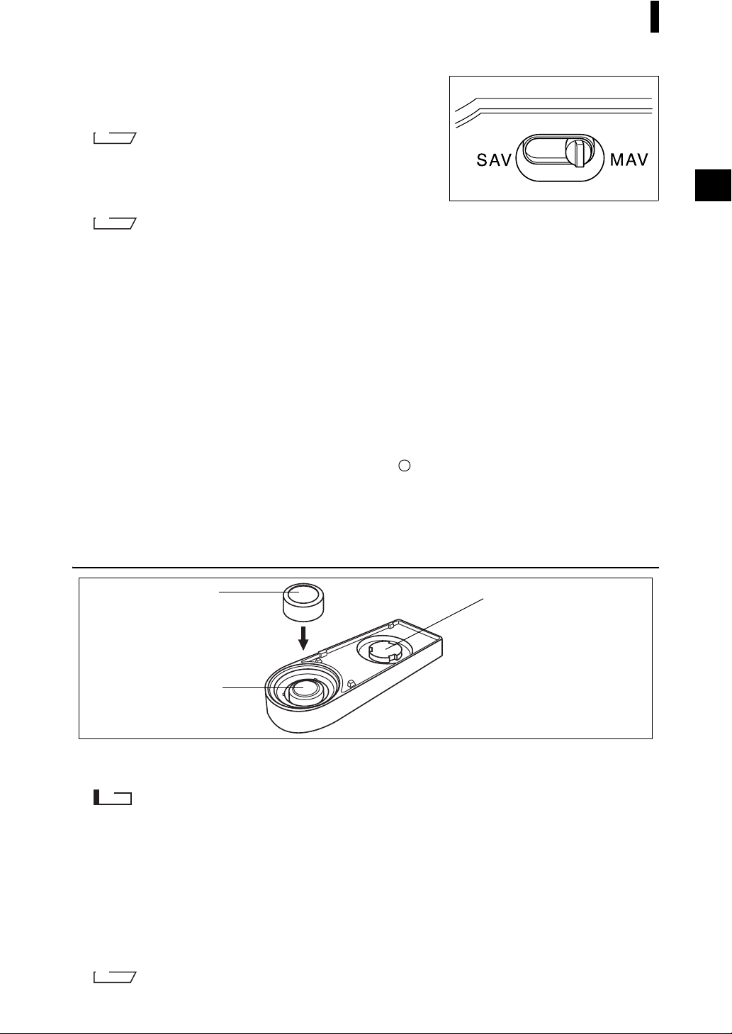
6 Measurement area selector
Used to change the lens position according to the measurement area.
M
emo
This switch is not available with the CM-2500d.
7 Measuring button (MEAS. button)
Press this button to perform calibration or measurement.
M
emo
When setting measurement conditions or tolerances, this button can be used as UNDO button to return to the
previous item.
8 External output terminal
To transfer data to an external device, connect the RS-232C cable (IF-A16) or printer cable (CR-A75)
to this terminal.
9 Battery cover
A cover for the battery chamber. Four AA-size batteries must be set in the battery chamber in the correct polarity direction.
0 AC adapter terminal
When using the AC adapter (AC-A17), connect the adapter’s plug to this terminal.
A POWER switch
Used to turn ON/OFF power. Setting this switch to “ ” turns the power OFF, and setting it to “|”
turns the power ON.
B Measuring Base
Use this base to attach the specimen securely to the instrument when analyzing small specimens.
White Calibration Plate CM-A145
1
2
1 Cap
A cap provided to protect the White Calibration Plate.
3
Note
If you are not going to use the White Calibration Plate, attach the cap to the White Calibration Plate to prevent
exposure to ambient light and protect it from scratches and dust.
2 White Calibration Plate
Used to perform white calibration of the CM-2600d/2500d.
If you are not going to use it, attach the cap to prevent exposure to ambient light and protect it from
scratches and dust.
3 Target Mask mount section
Used for storing a Target Mask that is not in use.
M
emo
For attaching/removing a Target Mask, refer to “Attaching/Removing a Target Mask” (page E-14).
E-13
Page 16
Preparation
Attaching/Removing a Target Mask
With the CM-2600d, a Target Mask conforming to the selected lens position and measurement condition
must be used. A Target Mask that is not in use can be attached to the Target Mask mount section of the
White Calibration Plate, so that it can be stored together with the instrument.
To attach/remove a Target Mask, follow the procedure given below.
M
emo
To facilitate attaching/removing a Target Mask, turn the instrument over so that the specimen measuring port is face
up.
Note
• When attaching/removing a Target Mask, take care not to allow dirt and dust to enter the integrating sphere
though the measuring port.
• Do not exert excessive force on the latch of the Target Mask. Doing so may damage the latch, disabling use of
the Target Mask.
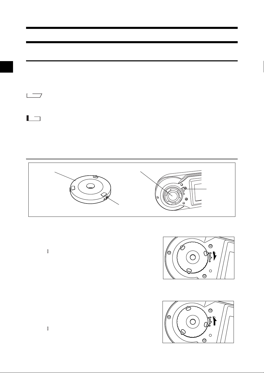
Attaching/Removing a Target Mask to/from the Instrument
Target Mask
Attaching a Target Mask
1. Place the Target Mask on the specimen measuring
port so that the marker on the latch is aligned with
the “
2. Hold the outer edge of the mask, and turn it in the
direction of the arrow (clockwise) until the marker
on the latch is aligned with the “o” marker on the
port.
Removing the Target Mask
1. Hold the outer edge of the mask, and turn it in the
opposite direction to the arrow (counter-clock
wise) until the marker on the latch is aligned with
the “
” marker on the port.
” marker.
Specimen measuring port
Latch
Positioning
marker
-
2. Hold the outer edge of the mask and remove it.
E-14
Page 17
Preparation
2
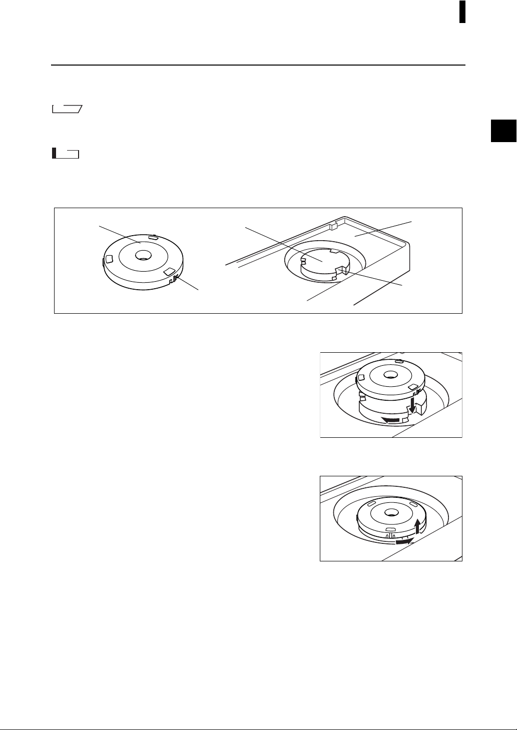
Storing a Target Mask
In the case of the CM-2600d, a Target Mask that is not in use can be attached to the Target Mask mount
section of the White Calibration Plate, so that it can be stored together with the instrument.
M
emo
Even in the case of the CM-2500d, when the Target Mask is removed for cleaning the integrating sphere, it can be
attached to the
Target Mask mount section of the White Calibration Plate to prevent loss and damage.
Note
• Do not touch the inner surface of the Target Mask or allow it to get dirty and scratched.
• Do not exert excessive force on the latch of the Target Mask. Doing so may damage the latch, disabling use of
the Target Mask.
Target Mask
Attaching a Target Mask
1.
Place the Target Mask on the Target Mask mount
section so that the inner surface of the latch is
aligned with the notch on the White Calibration
Plate.
2. Hold the outer edge of the mask and turn it clock-
wise to secure it.
Removing the Target Mask
1.
Hold the outer edge of the mask and turn it counter-clockwise until the inner surface of the latch is
aligned with the notch on the White Calibration
Plate.
2. Hold the outer edge of the mask and remove it.
Target Mask mount section
Latch
Notch
2
111
White
Calibration
Plate
11
2
2
E-15
Page 18
Preparation
Attaching/Removing the “Measuring Base”
A “Measuring Base” has been included with the Spectrophotometer CM-2600d/2500d.
This allows small specimens to be attached securely to the instrument when they are being measured, and
this enables more accurate measurements to be made.
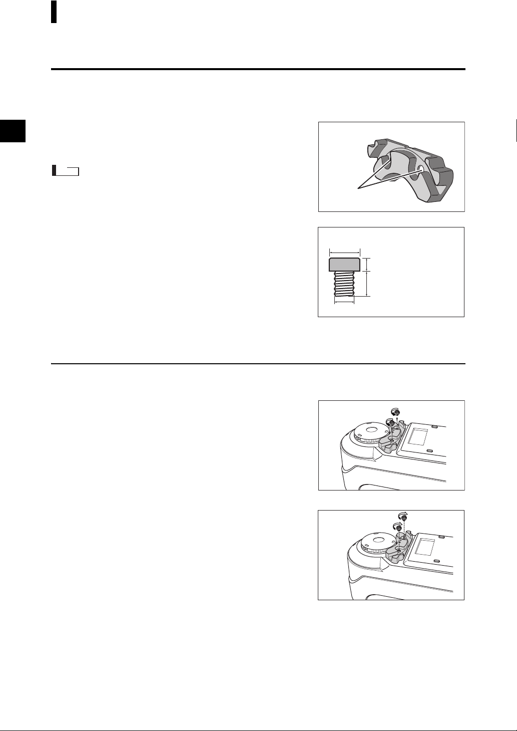
The “Measuring Base” is shown in the illustration to the right,
and is attached to the base of the CM-2600d/2500d with two
Measuring Base
screws.
Note
• Make sure that the “Measuring Base” is securely attached to the
instrument before calibrating the instrument or taking measure
ments.
• You must remove the “Measuring Base” before using the optional
Zero Calibration Box or Dust Cover Set.
• When removing the “Measuring Base”, make sure that the screws
used to attach the base to the instrument are stored properly and
are not mislaid.
If the screws do become mislaid, replace them with screws that
meet the specifications shown to the right.
[Screw name]
Cross-Recessed Pan Head Machine Screw M3, Nominal Length 4-5 mm
Attaching/Removing the “Measuring Base” to/from the Instrument
Removing the “Measuring Base”
1. Place the CM-2600d/2500d so that its base is fac-
ing up and it is stable.
-
“Measuring Base”
attachment hole
Specifications for “Measuring Base” attachment screws
Diameter of screw head (head diameter): φ5-6.5 mm
Thickness of screw head
(head height): less than 3 mm
Length of screw body
(body length): 4- 5 mm
Screw diameter: φ3 mm
Terms in parenthesis () are JIS defined terms for parts of screws
2. Using a crosshead screwdriver, turn the two attach-
ment screws counter-clockwise and remove them.
Use a crosshead screwdriver that is a suitable size for the screws.
Attaching the “Measuring Base”
1. Place the CM-2600d/2500d so that its base is fac-
ing up and it is stable.
2. Place the “Measuring Base” on the base of the
CM-2600d/2500d as shown in the illustration.
Place the “Measuring Base” so that it is aligned with the attach-
ment holes in the base of the CM-2600d/2500d. When placing the
“Measuring Base” on the base of the CM-2600d/2500d, make sure
that nothing is trapped between the instrument and the base.
3. Using a crosshead screwdriver, turn the two at-
tachment screws clockwise and tighten them securely.
Do not tighten the screws too tightly.
E-16
Page 19
Preparation
Cleaning Each Part
This section explains how to clean the White Calibration Plate, Target Mask and inside of the integrating
sphere.
White Calibration Plate
Gently wipe off dirt with a soft dry cloth. If dirt is difficult to remove, dampen a cloth with commercially
available lens cleaning liquid and wipe. Then remove the liquid with a cloth dampened with water, and
leave it to dry.
Note
Take care not to scratch the White Calibration Plate.
Target Mask
Use a blower to remove dirt and dust from the Target Masks.
Note
Do not touch the inner surface of the Target Masks with your fingers or wipe them with a cloth. If the Target
Masks are so dirty that dirt cannot be removed with a blower, contact the nearest KONICA MINOLTA SENSINGauthorized service facility.
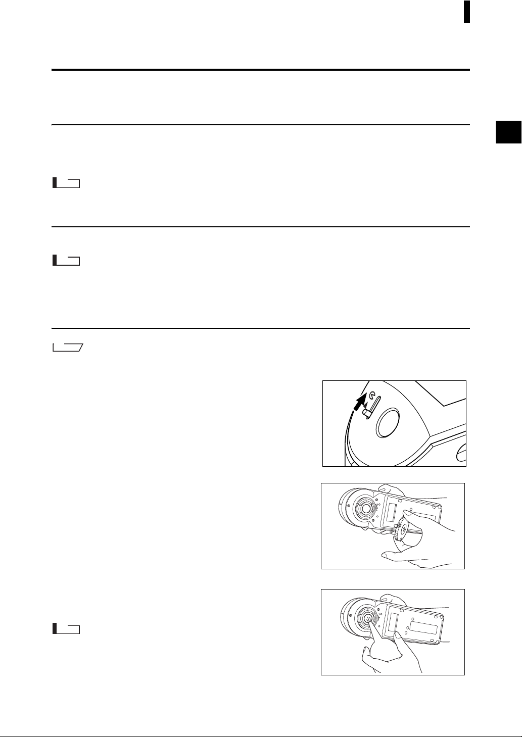
Inside the Integrating Sphere
M
emo
For attaching/removing a Target Mask, refer to “Attaching/Removing a Target Mask” (page E-14).
1. To prevent dust and dirt entering the optics sec-
tion from the integrating sphere, slide the viewfinder lever to open the viewfinder.
2. Remove the Target Mask.
3. Use a blower to remove dirt and dust from the in-
tegrating sphere.
Note
Do not touch the white-coated inner surface of the integrating
sphere, wipe it with a cloth or put any object inside it. If the surface
is so dirty that dirt cannot be removed with a blower, contact the
nearest KONICA MINOLTA SENSING-authorized service facility.
E-17
Page 20
Preparation
Inserting the Batteries
To supply power to the instrument, the AC adapter (AC-A17) or four AA-size batteries (Alkaline or NiMH battery is recommended for better service life) must be used. Use either the AC adapter or batteries,
according to which suits your application.
Note
• If you are not going to use the instrument for more than two weeks, make sure that the batteries are removed.
If the batteries are left in the instrument for long periods of time, battery electrolyte may leak and damage the
instrument.
• Do not use batteries of different types or mix new batteries with old ones. Doing so may result in battery explosion or reduction of battery life.
• Do not touch or short-circuit the terminals inside the battery chamber. Doing so may result in breakdown of
the instrument.
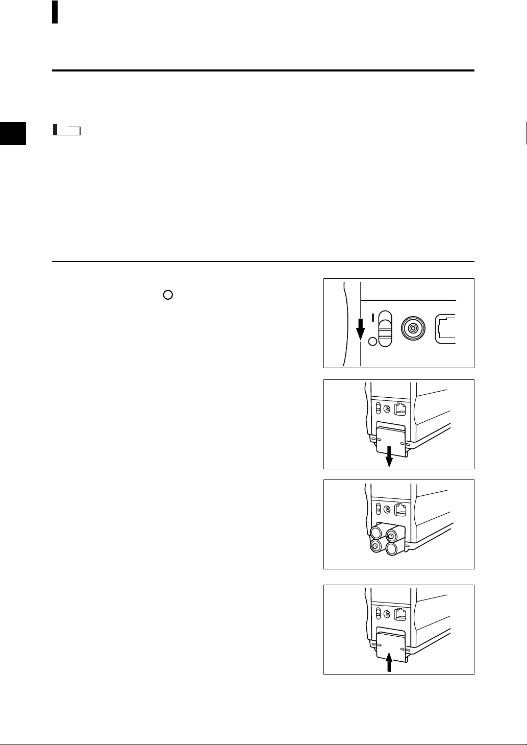
[Operating Procedure]
Make sure that power is OFF (i.e. the POWER
1
switch is set to “ ”).
Slide the battery cover on the rear of the instru-
2
ment to open it.
Place four AA-size batteries in the battery
3
chamber. Make sure that the batteries are
placed in the correct direction.
Align the marker on the battery cover with that
4
on the instrument, and slide the battery cover
to close it.
E-18
Page 21
Preparation
Connecting the AC Adapter
M
emo
Use of the AC adapter (AC-A17) rather than batteries is recommended, since more power will be required when the
external output terminal is used to output data to an external device or print it.
Note
• To supply AC power to the instrument, always use the AC adapter (AC-A17) supplied with the instrument.(Rated: 5 V, 2.8 A)
• Before connecting or removing the AC adapter, make sure that power is turned OFF.
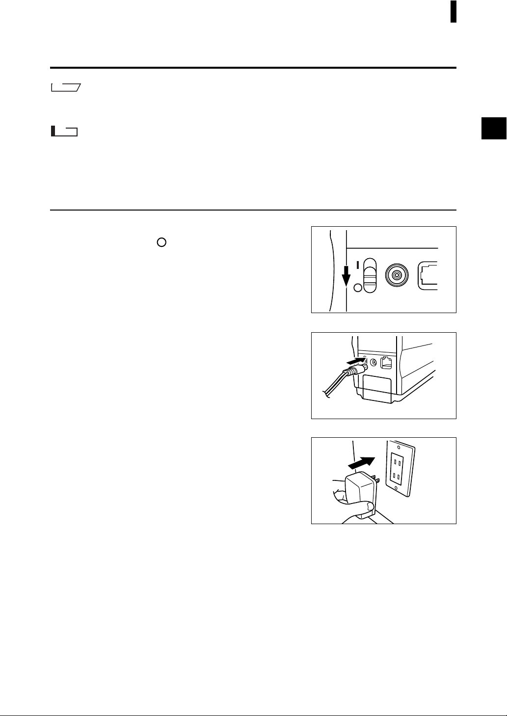
[Operating Procedure]
Make sure that power is OFF (i.e. the power
1
switch is set to “ ”).
Connect the AC adapter’s connector plug to
2
the AC adapter terminal on the rear of the instrument.
Insert the AC adapter’s power plug to an AC
3
outlet (100-240 VAC, 50-60 Hz).
AC outlet
E-19
Page 22
Preparation
Turning Power ON
Note
When turning the power ON for the first time, the display language and measurement mode must be set.
For details, refer to page E-27.
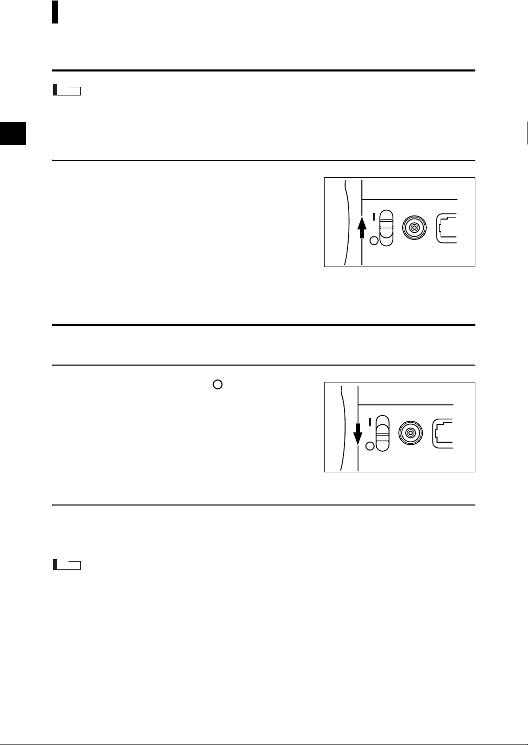
[Operating Procedure]
Set the POWER switch to “|”.
1
The power will be turned ON.
Turning Power OFF
[Operating Procedure]
Set the POWER switch to “ ”.
1
The power will be turned OFF.
Auto Power Save Function
Power save mode will be activated if the MEAS. button and navigation wheel are not operated for more
than three minutes. During power save mode, the flash circuit will not be charged. To cancel power save
mode, press the MEAS. button to start measurement.
Note
• If the MEAS. button is pressed to cancel power save mode, start of measurement will be delayed by a few seconds, so keep the instrument still until the lamp flashes and measurement is taken.
• The auto power save function is not available in remote mode (see page E-89).
E-20
Page 23
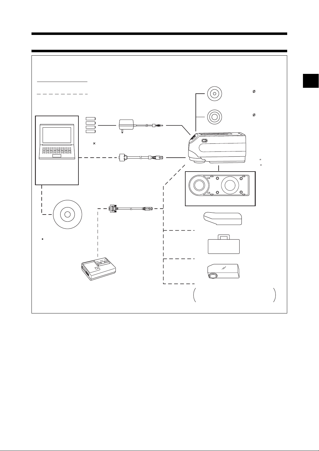
System Configuration
Standard accessories
Optional accessories
Target Mask 3 mm
CM-A147
* Not supplied with the
CM-2500d.
Target Mask 8 mm
CM-A146
AA-size battery
Personal computer
(commercially available)
Color Data Software
SpectraMagic NX
(CM-S100w)
Printer (commercially available)
* For details to output data to a printer,
refer to page E-91.
( 4)
AC Adapter
AC-A17
RS-232C Cable
IF-A16
Printer Cable
CR-A75
CM-2600d
(CM-2500d)
* with Measuring
Base
White Calibration Plate CM-A145
C
alibration Box CM-A32
Zero
Hard Case CM-A148
Dust Cover Set CM-A149
Replacement Dust Cover CM-A152
(polyolefin)
E-21
Page 24
Items You Must Know
Language Mode
Contents on the LCD screen can be displayed in English, Japanese, German, French, Spanish or Italian.
In this manual, explanation of operating methods and display is given for English mode.
Measurement Mode
Two measurement modes (COND and TASK) are available with this instrument, and can be switched
from one to another.
Measurement Mode Application
Normal measurement mode. Measurement can be performed while the con-
COND mode
TASK mode
ditions are changed. In this mode, up to six sets of conditions (illuminant,
observer angle, color space etc.) can be registered.
Special measurement mode. For continuous inspection, this mode allows
you to perform measurement while messages indicating the measurement
procedure are displayed on the LCD. The messages can be created by use of
the previously used software SpectraMagic (Ver.3.2 or higher; except for
Ver. 3.5) with your PC. In this mode, color differences can be calculated one
by one against up to 10 color difference target data.
Note
• Before starting measurement, tasks (measurement procedure) must be downloaded from the PC using SpectraMagic (Ver.3.2 or higher; except for Ver.3.5).
TASK mode cannot be selected if no tasks have been downloaded.
• During TASK mode, only the data measured last is displayed. Use of SpectraMagic (Ver.3.2 or higher; except for Ver.3.5) allow you to access to previous data
in the memory.
Up to six sets of conditions can be registered either in COND or TASK mode.
In the case of COND mode:
E-22
Page 25
Items You Must Know
Target Modes
• The CM-2600d/2500d supports two Target Modes, “defined in COND.” mode and “linked to each data.”
mode, to analyze both measurement data and color difference. As with Language Mode and Measurement
Mode, you can select the desired mode when you turn the power ON.
• The default setting is “linked to each data.” mode. To switch to “defined in COND.” mode or switch between
the target modes, you need to follow the procedure to select target mode.
• Depending on the target mode selected, the display and the procedure for some operation for the instrument
are different.
Below are some examples of these differences. (For details, see Target Mode in the Appendix.)
Note
Once the target mode is changed, previous data will be cleared. It is recommended that you save previous data
into other storage media in advance by using the Color Data Software that is optionally available.
• In “linked to each data.” mode, the next color difference data number is displayed next to the currently
selected color difference data number in the initial settings screen.
When “defined in COND.” mode is selected, it is not displayed.
• In “linked with each data” mode, to display the color difference for measurement data, you can only select
the color difference for the currently selected measurement data. When “defined in COND.” mode is se
lected, you can freely select the color difference data number after making measurements. You can also
display the results of the selection.
• Data storage capacity for the “linked to each data.” mode is 1700 pieces, and that for the “defined in
COND.” mode is 700 pieces.
-
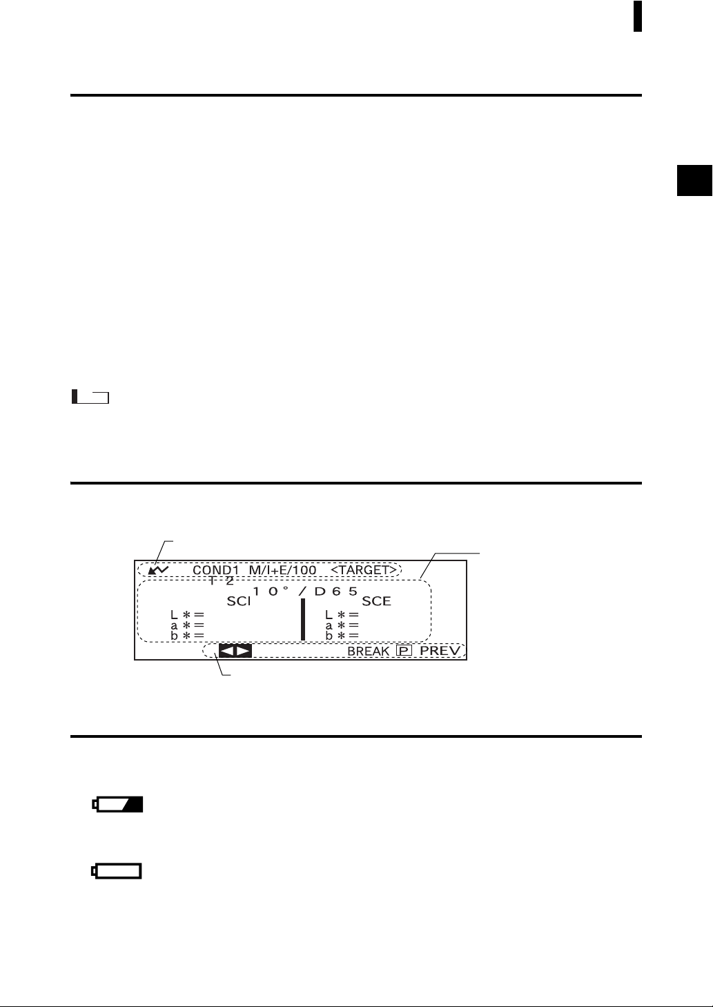
Screen Display
The basic screen structure is shown below.
Data No. and screen title are displayed.
Items that can be used are displayed.
Conditions and measurement
results are displayed.
Battery Alarm
When using CM-2600d/2500d with batteries, battery alarm indication appears when their power level
lowers.
[Half battery indication]
If this indication (Half battery indication) appears, new batteries should be prepared for replacement
in near future. Even with this indication displayed, measurements are still possible.
[Empty battery indication]
If this indication (Empty battery indication) appears, measurement or calibration is no longer possible. Replace batteries with new ones.
E-23
Page 26

Items You Must Know
Data Saving
Data used with this instrument is saved automatically. Although white calibration data is retained in internal memory even after power is turned off, it is still necessary to repeat white calibration each time
you switch the power back on.
E-24
Page 27

Chapter 2
Preparation for Measurement
E-25
Page 28
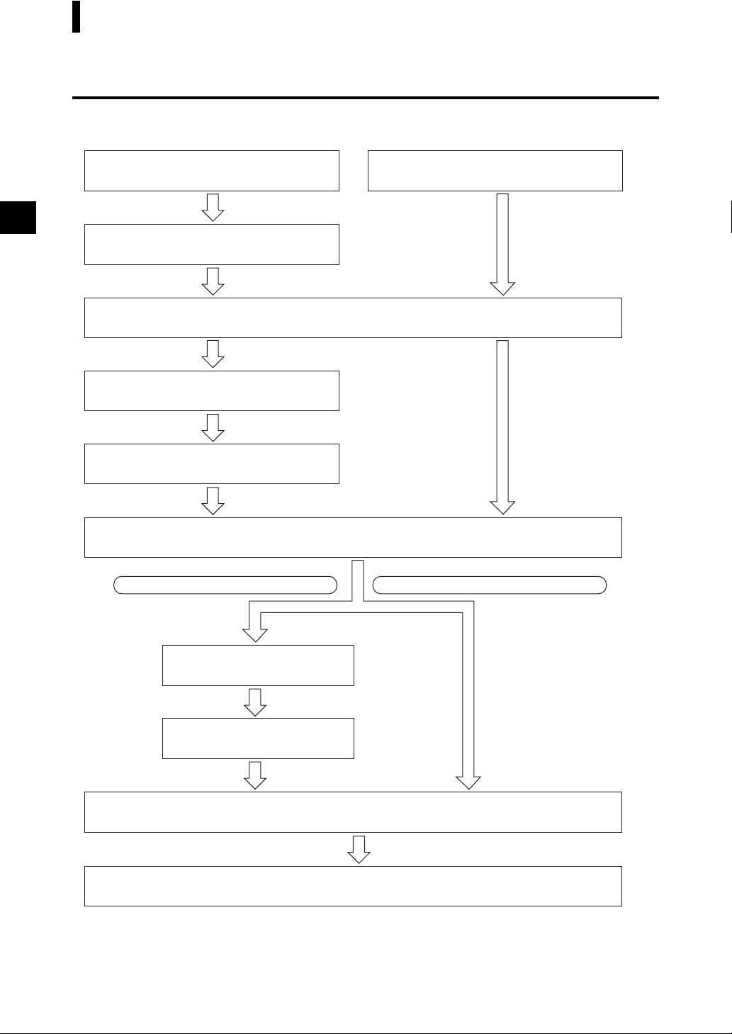
Flow of Measurement
For the first time
Turning Power On for the First Time
(see page E-27)
Initial Setting (see page E-29)
Selecting a Measurement Condition (see page E-33)
Setting a Measurement Condition
(see page E-34)
Zero Calibration (see page E-44)
For the second and subsequent times
Turning Power ON (see page E-20)
White Calibration (see page E-46)
When Checking Color Difference
Setting a Color Difference
Target Data (see page E-48)
Selecting a Color Difference
Target Data (see page E-50)
Measurement (see page E-60)
Complete Measurement
When Not Checking Color Difference
E-26
Page 29
Turning Power On for the First Time
When turning the power ON for the first time, the display language and measurement mode must be set.
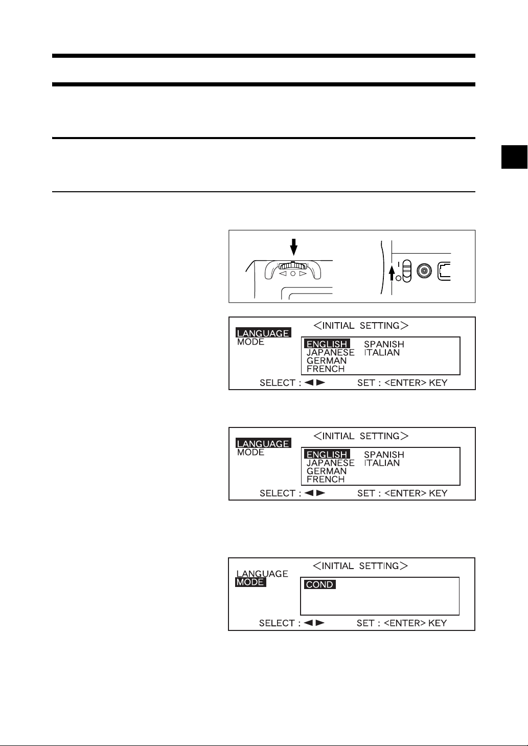
Setting the Language Mode and Measurement Mode
Set the language and measurement mode as follows:
[Setting Procedure]
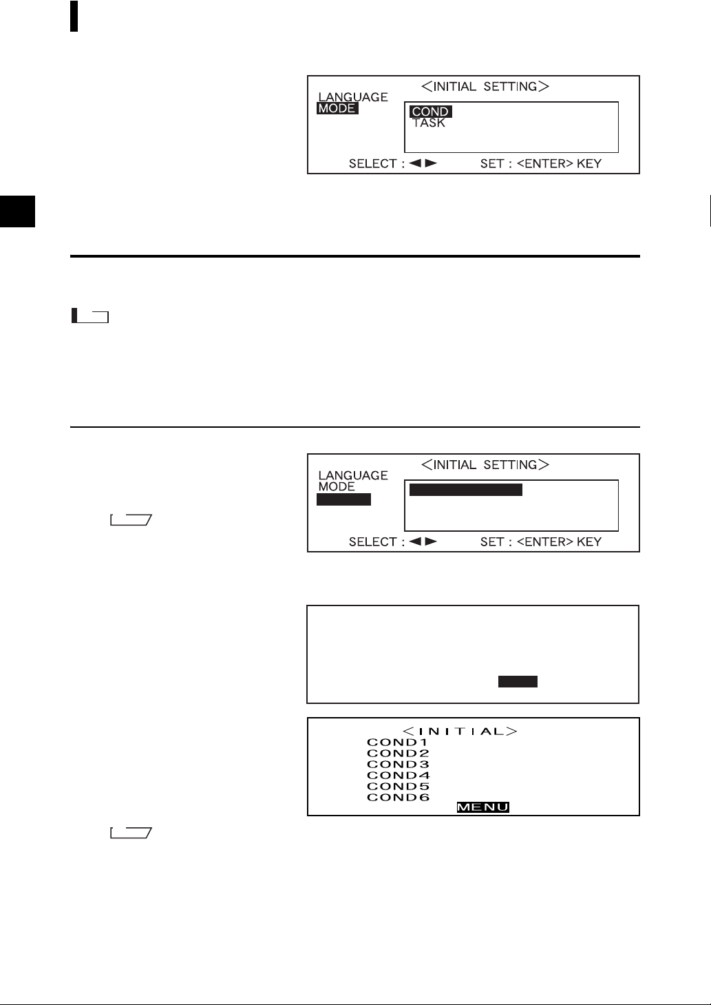
While pressing A, turn the power ON.
1
The <INITIAL SETTING> screen
will appear, with the item “LAN
GUAGE” highlighted.
-
TARGET
(Back side)
Turn B to select the desired language, then press A.
2
TARGET
• When the cursor moves to the desired language, all the text will be displayed in the selected language.
Turn B to select the desired measurement mode, then press A.
3
TARGET
• If no tasks have been downloaded to the instrument, only “COND” will be displayed.
E-27
Page 30
Turning Power On for the First Time
TARGET
• If a task(s) has been downloaded to the instrument, both “COND” and “TASK” will be displayed.
• Select “COND”.
Selecting the Target Mode
The default setting is “linked to each data.” mode. The following procedure is required only if you want
to switch the target mode.
Note
• If the Color Data Software “SpectraMagic CM-S9w” is used, switch the target mode to “defined in COND.”
mode.
• Once the target mode is changed, previous data will be cleared. It is recommended that you save previous data
into other storage media in advance by using the Color Data Software that is optionally available.
[Setting Procedure]
Turn B to select the de-
1
sired target mode, then
press A.
M
emo
If you do not want to change the target mode, press A.
• The default setting is “linked to each data.”.
A warning message is displayed.
Turn B to select “Yes”,
2
then press A.
The <INITIAL> screen will appear.
M
emo
If you select “No” and press A, you will return to the screen shown in 1.
TARGET
Measurement data and color difference
target color data stored in the
instrument are all deleted.
Are you sure to delete all data?
linked to each data.
defined in COND.
YES NO
E-28
Page 31

Initial Setting
The following five initial setting items are available.
(1) REMOTE..................... Connects the instrument to the PC to enable bi-directional communications.
(2) AUTO PRINT.............. If the instrument is connected to a printer, measured data will be printed au-
tomatically each time measurement is taken.
(3) CLOCK........................ Adjusts the instrument’s built-in clock.
(4) DISPLAY INVERT..... Reverses the display direction.
(5) LCD CONTRAST ....... Adjusts the LED’s contrast.
M
emo
“(1) REMOTE” and “(2) AUTO PRINT” can be used when connecting the instrument to a PC or printer.
The settings will be kept even if the power is turned OFF.
To make initial settings, follow the procedure given below:
[Setting Procedure]
Turn the power ON.
1
Turn B to select “MENU”, then press A.
2
The <MENU> screen will appear.
The initial settings can be made in
this screen.
E-29
Page 32

Initial Setting
Setting the Date and Time
[Setting Procedure]
<MENU> screen
Turn B to select “CLOCK”, then press A.
1
Turn B to select “ADJUST”, then press A.
2
The cursor will move to the current-
ly set date, allowing you to change
it.
Turn B to select the desired date and time, then press A.
3
The selected date and time will be
set.
• Each time A is pressed, the cursor will move as follows:
“day” → “month” → “year” → “hour” → “minute” → “second” → “PREV”
• Keeping B held down to left or right will cause the date/time to change continuously.
• To change the entries, restart from step 2.
<Settings>
• Day: 01 to 28, 29, 30, 31 (varies with the selected month)
• Month: 01 to 12
• Year: 00 to 99 (lower two digits)
• Hour: 00 to 23
• Minute: 00 to 59
• Second: 00 to 59
Turn B to select “PREV”, then press A.
4
The settings you made at step 3 will
be confirmed, and the <MENU>
screen will reappear.
E-30
Page 33

Setting the Display Direction
[Setting Procedure]
<MENU> screen
Turn B to select “DISPLAY INVERT”, then press A.
1
The contents displayed on the LCD
will be reversed each time
pressed.
A is
Initial Setting
E-31
Page 34

Initial Setting
Setting the LCD Contrast
[Setting Procedure]
<MENU> screen
Turn B to select “LCD CONTRAST”, then press A.
1
Turn B to adjust the LCD contrast, then press A.
2
The contrast you set will be con-
firmed, and the <MENU> screen
will reappear.
• Turning B to the right will move the contrast adjuster bar to the right, increasing the contrast.
Turning
• Keeping B held down to left or right will cause the contrast adjuster bar to move continuously.
B to the left will move the contrast adjuster bar to the left, decreasing the contrast.
Note
On the LCD of this instrument, the display looks darker in a high temperature environment, and looks
paler in a low temperature environment. When this occurs, adjust the display level so that the display
shows its contents properly.
If the contrast is too high or too low, the contents displayed on the LCD cannot be viewed properly. In this
case, turn the power OFF, and then turn it ON again while pressing A. The default contrast will be
stored and the screen shown in “Setting the Language and Measurement Mode” (page E-27) will appear.
Adjust the LCD contrast again as explained in “Initial Setting” (from page E-29) if necessary.
E-32
Page 35

Selecting a Measurement Condition
Before starting measurement, the desired measurement condition (COND1 to COND6) must be selected.
M
emo
• Up to six sets of measurement conditions (COND1 to COND6) can be set.
• Measurement conditions must be set before start of measurement. For details, refer to page E-34.
[Setting Procedure]
<INITIAL> screen
Turn B to select one of the conditions (COND1 to COND6), then press A.
1
Turn B to select “FILE”, then press A.
2
• “T*” is the number of the color difference target data for the next measurement. If nothing is selected,
“T---” appears.
• “T*” does not appear if “defined in COND.” mode is selected.
The currently selected measure-
ment condition will be dis-
played.
• The FILE screen consists of two pages (1/2 and 2/2).
• The pages can be switched from one to another by turning B to select “ 2/2” (or “ 1/2”) and
then pressing A.
M
emo
• To set a new condition or change an existing condition, refer to “Setting a Measurement Condition” on the
following page.
• If an maesurement condition has been set, calibration and measurement can be performed under that condition.
E-33
Page 36

Setting a Measurement Condition
Up to six sets of conditions (COND1 to COND6) can be set. Since the instrument will perform measurement according to the selected condition, conditions must be set before start of measurement.
The following nine condition items can be set:
(1) Measurement area and specular component “MASK/GLOSS”
(2) UV setting (UV SETTING)
(3) Illuminant 1, illuminant 2 “ILLUMINANT 1, ILLUMINANT 2”
(4) Observer “OBSERVER”
(5) Display contents “DISPLAY”
(6) Color space “COLOR SPACE”
(7) Measurement times and standard deviation for manual averaging
“MANUAL AVG. TIMES” and “DEVIATION”
(8) Auto averaging times “AUTO AVG.”
(9) Delay time “DELAY TIME”
M
emo
• A setting can be made for the currently highlighted item. To confirm the setting, press A. The next item will
be highlighted automatically.
• For the items for which no setting needs to be made, press A to skip them.
• If an incorrect setting has been made for items (1) to (9), press the MEAS. button. This will take you to the previous
items and allow you to make a correct setting.
[Setting Procedure]
<FILE> screen
Turn B to select “SEL”, then press A.
1
For CM-2600d
“MASK/GLOSS” will be highlight-
ed.
For CM-2500d
E-34
• Only those conditions whose measurement area is MAV can be selected.
Page 37

Setting a Measurement Condition
Setting the Measurement Area and Specular Component Mode
Turn B to select the desired setting, then press A.
2
<Settings>
• M/I+E: Measurement area:ø8 mm, simultaneous measurement of SCI (Specular Component Included) and SCE (Specular Component Excluded)
• M/SCI: Measurement area:ø8 mm, SCI (Specular Component Included)
• M/SCE:Measurement area:ø8 mm, SCE (Specular Component Excluded)
• S/I+E: Measurement area:ø3 mm, simultaneous measurement of SCI (Specular Component Included) and SCE (Specular Component Excluded)
• S/SCI: Measurement area:ø3 mm, SCI (Specular Component Included)
• S/SCE: Measurement area:ø3 mm, SCE (Specular Component Excluded)
• The measurement area that suits the Target Mask used for measurement or the setting of the lens po-
sition selector switch must be selected.
• With the CM-2500d, only “M/
” can be selected.
***
If the mask type has been changed
from “M/
versa, a message will appear when
A is pressed, inform you that
the mask (measurement area) has
been changed. The next item will
then appear automatically.
***
” to “S/
***
” or vice
E-35
Page 38

Setting a Measurement Condition
Setting the UV
Turn B to select “UV SETTING”, then press A.
3
For CM-2600d
<Settings>
• UV100%: Measurement is performed with an illumination that contains all UV components of Xe flash
light source.
• UV0%: Measurement is performed with an illumination that contains no UV components of Xe flash light
source.
• UVADJUSTED: This item can be selected only if UV coefficients have been downloaded from Spec-
traMagic (Ver.3.2 or higher; excluded Ver.3.5).
For CM-2500d
• Only “UV100%” can be selected.
Selecting Illuminant 1
Turn B to select the desired illuminant, then press A.
4
<Settings>
• D65: Standard illuminant D65; daylight, Color temperature: 6504K
• D50: Complementary illuminant D50; daylight, Color temperature: 5003K
• C: Complementary illuminant C; daylight (Ultraviolet part is small in comparison with the daylight),
Color temperature: 6774K
• A: Standard illuminant A; Incandescent lamp, Color temperature: 2856K
• F2: Cool white (fluorescent lamp)
• F6: Cool white (fluorescent lamp)
• F7: Color rendering A daylight white (fluorescent lamp)
• F8: Color rendering AAA natural white (fluorescent lamp)
• F10: 3-band type natural white (fluorescent lamp)
• F11: 3-band type cool white (fluorescent lamp)
• F12: 3-band type warm white (fluorescent lamp)
• ---: None (Not selectable “ILLUMINANT 1”)
E-36
Page 39

Setting a Measurement Condition
Selecting Illuminant 2
As explained in “Selecting Illuminant 1”, select the desired illuminant, then press
5
A.
<Settings>
• Same as those given in “Selecting Illuminant 1”
• To display MI (metamerism index), an illuminant must be selected for ILLUMINANT 2.
Selecting the Observer
Turn B to select the desired observer angle, then press A.
6
<Settings>
• 10°: 10° observer (CIE1964)
• 2°: 2° observer (CIE1931)
E-37
Page 40

Setting a Measurement Condition
Selecting the Display Mode
Turn B to select the desired display mode, then press A.
7
<Settings>
• DIFF&ABS:
Displays the absolute value and the color difference in relation to the target color. (Only absolute value or
only color difference can be displayed.)
If pass/fail judgment is made according to the specified box color difference tolerances, the failed factor
of the measured data will be highlighted.
• PASS/FAIL:
Whether color difference from the target colors is within the specified color difference limit is judged.
“PASS” will be displayed if the color difference is within the specified limit for all items of the measured
data, and “FAIL” will be displayed if not within the specified limit for any factor of the measured data.
• COLOR GRAPH:
Displays the color difference from the target value in a graph. (Only for illuminant 1, box tolerance and
L*a*b*)
• SPECT. GRAPH:
Displays a spectral reflectance graph.
• ASSESSMENTS
The color difference from the target color, pass/fail judgment result made based on the specified tolerances
and direction of deviation from the target color for each axis in the L*a*b* or L*C*h color space are dis
played.
• If no color target has been selected, the color difference, pass/fail judgment result and tint deviation
direction will not be displayed even if “ASSESSMENTS” is selected. Furthermore, if no tolerances
are selected, the pass/fail judgment result and deviation direction will not be displayed even if the
target color is selected.
-
E-38
• Even if “DIFF&ABS” or “COLOR GRAPH” is selected, no color difference values will be displayed
if no color difference target data have been selected.
Page 41

Selecting a Color Space
Turn B to select the desired color space, then press A.
8
Locating the highlighted cursor to
by turning B will display
the next page of the color space list.
Locating the highlighted cursor to
by turning B will display
the previous page of the color space
list.
Setting a Measurement Condition
<Settings>
• L*a*b*, E*: L*a*b* color space and color difference by “ E*ab (CIE1976)” color-difference formula
• L*C*h, E*: L*C*h color space and color difference by “ E*ab (CIE1976)” color-difference formula
• L*C*h, CMC1:1: L*C*h color space and color difference by “CMC1:1” color-difference formula
• L*C*h, CMC2:1: L*C*h color space and color difference by “CMC2:1” color-difference formula
• XYZ: XYZ color space
• L*C*h, CIE94: L*C*h color space and color difference by “ E*94 (CIE1994)” color-difference formula
• Hunter Lab: Hunter Lab
• Yxy: Yxz color space
• MUNSELL: Munsell color notation
• WI ASTM E313: Whiteness (ASTM E313-73)
• WI CIE: Whiteness Index
• YI ASTM E313: Yellowness Index (ASTM E313-73)
• YI ASTM D1925: Yellowness Index (ASTM D1925)
• B ISO 2470: ISO Brightness
• DENSITY (A): Density (status A)
• DENSITY (T): Density (status T)
• Wl, Tint Ganz: Whiteness Index and Tint value (Ganz & Griesser)
• Wl, Tint CIE: Whiteness Index and Tint value (CIE)
• L*a*b*, CIE00: L*a*b* color space and color difference by “ E*00 (CIE2000)” color-difference formula
• L*C*h, CIE00: L*C*h color space and color difference by “ E*00 (CIE2000)” color-difference formula
• If L*a*b* or L*C*h is selected as the color space, DIFF&ABS or PASS/FAIL as the display mode
and ILLUMINANT 1 or ILLUMINAT 2 as the illuminant, it will be possible to calculate MI (meta
merism index) and display the result.
• Even if “WI, Tint Ganz” is selected, no data for WI and Tint (Ganz/Griesser) will be displayed when
using SpectraMagic NX or the previously used software SpectraMagic Ver.3.2 or higher (except for
Ver. 3.5), unless the proper Ganz coefficient has been specified and UV ADJUSTED is selected in the
UV SETTING in the Measurement Condition Setting.
In addition, if the Ganz coefficient is re-specified after measurement, the measurement data will be
replaced with the one that is calculated based on that Ganz coefficient.
-
E-39
Page 42

Setting a Measurement Condition
• The coefficient for CIE00 (kl:kc:kh) is (1:1:1). This can be changed using SpectraMagic NX (except
for Ver. 1.50 or earlier).
If the coefficient (kl:kc:kh) is re-specified after measurement, the measurement data will be replaced
with data calculated based on the new coefficient.
E-40
Page 43

Setting a Measurement Condition
Setting the Number of Measurements for Manual Averaging
Manual averaging settings can be made as follows: For details, refer to “Manual Averaging” (page E-76).
Turn B to select the number of measurements to be performed, then press
9
A.
<Settings>
• TIMES:
Specify the number of measurements to be performed (2 to 30).
If “- -” is selected, manual averaging will not be performed.
• Keeping B held down to left or right will cause the value to change continuously.
Setting the Standard Deviation for Manual Averaging
Turn B to set the desired standard deviation, then press A.
10
<Settings>
• DEVIATION:
Set the desired standard deviation (0.01 to 2.00). When the standard deviation is below the specified value,
the average of the measured values taken so far will be calculated and used as the measurement result.
If “- -” is selected, manual averaging by the standard deviation will not be performed.
• If “- -” has been set for TIMES, “- - - -” will also be set for DEVIATION and cannot be changed.
• If the spectral graph has been selected as the display mode, “- - - -” will be set for DEVIATION and
can not be changed.
• The standard deviation can be set only if L*a*b* or L*C*h has been set as the color space.
• The standard deviation cannot be set if “SPECT. GRAPH” has been selected as the display mode.
• Manual averaging will end when either the specified number of measurements (TIMES) or the specified standard deviation (DEVIATION) is reached.
• Keeping B held down to left or right will cause the value to change continuously.
Setting the Number of Measurements for Auto Averaging
Turn B to select the number of measurements to be performed, then press A.
11
<Settings>
• Specify the number of measurements to be performed (1, 3, 5 or 8).
E-41
Page 44

Setting a Measurement Condition
Setting the Delay Time
Turn B to set the desired delay time, then press A.
12
<Settings>
• DELAY TIME:
The delay time is used to prevent influences caused by movement of the hands, and is the duration from
when the MEAS. button is pressed until the lamp flashes and measurement is performed. Specify the de
sired delay time (0.1 to 3.0 seconds in steps of 0.1 seconds). If “0.0” (second) is specified, no delay time
will be provided.
• Keeping B held down to left or right will cause the value to change continuously.
“BREAK” will be highlighted.
-
13
<Performing Calibration>
Turn B to select “PREV”, then press A.
Setting will be completed and the
<COND
• “T*” is the number of the color difference target data for the next measurement. If nothing is selected,
> screen will appear.
*
“T---” appears.
E-42
Page 45

Setting a Measurement Condition
• “T*” does not appear if “defined in COND.” mode is selected.
M
emo
Selecting “CALIBRATION” by turning B and pressing A will display the <CALIBRATION>
screen. So, perform the desired calibration according to step 3 and subsequent steps given in “Zero Calibra
tion” (from page E-44) or “White Calibration” (from page E-46).
Note
Depending on the target mode selected, some of the options displayed will be different.
<Performing Measurement>
Turn B to select “BREAK”, then press A.
The <measurement> screen will ap-
pear.
-
<Setting a Measurement Condition for another <COND*>
Turn B to select “PREV”, then press A.
Measurement condition setting
will be complete, and the
<COND
• “T*” is the number of the color difference target data for the next measurement. If nothing is selected,
“T---” appears.
> screen will reappear.
*
E-43
Page 46

• “T*” does not appear if “defined in COND.” mode is selected.
Selecting “PREV” by turning B and pressing A again will cause the <INITIAL> screen to reappear.
So, set another measurement condition according to the procedure giv-
en in “Selecting a Measurement
Condition” and “Setting a Measure
ment Condition” (from page E-34).
-
E-44
Page 47

Zero Calibration
Zero Calibration
When you use this instrument for the first time or when you have initialized it, zero calibration must be
performed.
Zero calibration is also sometimes required when measurement conditions are changed.
Once zero calibration is completed, the zero calibration data will be kept even if the power is turned OFF.
Thus, it is not necessary to perform zero calibration each time the power is turned ON.
M
emo
• The effects of stray light inside the measuring part (i.e. light generated due to the flare characteristics of the optical
system) will be compensated automatically by the zero calibration data.
• The amount of stray light may change because of dust or dirt which has collected in the optical system, temperature, repeated operation, vibration and shock exerted on the instrument. In this case, performing zero calibration
periodically is recommended.
Note
• If the instrument is not used for long periods of time, the zero calibration data stored in the instrument may be
lost. If the data is lost, zero calibration must be performed again.
• Before starting zero calibration, select the desired MASK/GLOSS setting from M/I+E, M/SCI, M/SCE, S/I+E,
S/SCI and S/SCE in the <FILE> screen. If M/
ed, set SAV to the instrument. For MAV, set the lens position selector switch and Target Mask to MAV. For
SAV, set them to SAV.
• A lens position error will occur if the lens position does not match the one set in the file, and a calibration error
will occur if the Target Mask does not match.
is selected, set MAV to the instrument. If S/
***
***
is select-
[Setting Procedure]
<INITIAL> screen
Turn B to select one of the conditions (COND1 to COND6), then press A.
1
Turn B to select “CALIBRATION”, then press A.
2
• “T*” is the number of the color difference target data for the next measurement. If nothing is selected,
“T---” appears.
• “T*” does not appear if “defined in COND.” mode is selected.
E-45
Page 48

Turn B to select “ZERO”.
3
Direct the specimen measuring port into the air.
4
1m or more
• Never place the specimen measuring port toward a light source.
• Keep the specimen measuring port more than 1m away from any reflective items (hands, desks,
walls etc.).
Make sure that is displayed, then press C (MEAS. button).
5
Zero calibration will be performed.
When zero calibration is complete,
the <CALIBRAITION> screen will
reappear.
E-46
M
emo
• Use of the optional Zero Calibration Box ensures proper zero calibration.
If Zero Calibration Box is used, remove “Measuring Base”.
• If does not appear due to the auto power save function, this may be due the fact that it can take time
to start zero calibration after C is pressed.
Note
• When zero calibration is complete, perform white calibration. Measurement cannot be performed if
white calibration has not been completed.
• Even though white calibration has been performed after the power is turned ON, if zero calibration has
also been performed after that, white calibration must be performed again.
Page 49

White Calibration
White Calibration
White calibration must be performed prior to start of measurement after the power is turned ON.
M
emo
• Own calibration data has been registered to the White Calibration Plate supplied with the instrument.
• Although white calibration data is retained in internal memory even after power is turned off, it is still necessary
to repeat white calibration each time you switch the power back on.
• The reading may fluctuate slightly due to changes in the ambient temperature or due to heat generation caused by
repeated operation of the instrument. In this case, make sure to perform white calibration regularly.
• White calibration is not required if you just want to see the measured data without performing measurement.
Note
• White calibration must be performed at the same temperature as the one at which measurement will be performed.
• Before starting white calibration, make sure that the instrument is sufficiently acclimatized to the ambient temperature.
• Before starting white calibration, select the desired MASK/GLOSS setting from M/I+E, M/SCI, M/SCE, S/I+E,
S/SCI and S/SCE in the <FILE> screen. If M/
ed, set SAV to the instrument. For MAV, set the measurement area selector switch and Target Mask to MAV.
For SAV, set them to SAV.
• A lens position error will occur if the lens position does not match the one set in the <FILE> screen, and a
calibration error will occur if the Target Mask does not match.
is selected, set MAV to the instrument. If S/
***
***
is select-
[Setting Procedure]
<INITIAL> screen
Turn B to select one of th3e conditions (COND1 to COND6), then press A.
1
Turn B to select “CALIBRATION”, then press A.
2
• “T*” is the number of the color difference target data for the next measurement. If nothing is selected,
“T---” appears.
• “T*” does not appear if “defined in COND.” mode is selected.
E-47
Page 50

Turn B to select “WHITE”.
3
Note that the White Calibration
Plate No. is displayed.
Place the instrument on the correct White Calibration Plate (i.e. the calibration
4
plate whose plate No. is displayed in the screen).
Make sure that is displayed, then press C (MEAS. button).
5
White calibration will be performed.
When white calibration is complete,
the measurement screen will reap
pear.
-
E-48
Note
The instrument's memory contains the calibration data of the White Calibration Plate supplied with instrument. Therefore, to execute white calibration, be sure to use the White Calibration Plate of the same
serial number as the number displayed on the <CALIBRATION> screen.
M
emo
• In COND mode, the measurement screen can still be displayed even if white calibration has not been completed. However, it will not be possible to take measurement. (Measured data can still be viewed.)
• White calibration must be performed each time the power is turned ON.
• To perform white calibration again after the measurement screen is displayed, select “PREV” to return to
<COND
• If the measurement area or specular component mode is changed in the <FILE> screen following white
calibration, it is necessary to perform white calibration again under those new conditions (i.e. with the
newly selected measurement area or specular component mode).
• Even if the conditions are changed (e.g. switched from COND2 to COND3) following white calibration,
it will be not necessary to perform white calibration again if the measurement area and specular component
mode remain unchanged.
• If does not appear due to the auto power save function, this may be due the fact that it can take time
to start white calibration after C is pressed.
> screen, then restart the procedure from step 2.
*
Page 51

Setting a Color Difference Target Data
Setting a Color Difference Target Data
To measure the color difference between two specimens, the color of one of the specimens must be set
as the target color. Up to 1700 target colors can be set for color difference measurement. (700 can be set
in the “defined in COND” mode.)
To set a target color, follow the procedure given below.
M
emo
• Since tolerances for pass/fail judgment need to be set for each target color, target color data must be set before
setting tolerances.
• The memory of this instrument can store up to 1700 pieces of data in total, (700 in the “defined in COND” mode).
This amount includes the sample data for the COND and TASK modes as well as color difference target data.
When some sample data have already been stored, the number of target colors which can be set will be reduced
by the number of the sample data.
Note
• Before setting target colors, a measurement condition (COND1 to COND6) must be selected and white calibration performed.
• For accurate measurement, make sure to keep measurement conditions (ambient temperature etc.) constant.
[Setting Procedure]
<COND*> screen
Turn B to select “TARGET”, then press A.
1
• “T*” is the number of the color difference target data for the next measurement. If nothing is selected,
“T---” appears.
• “T*” does not appear if “defined in COND.” mode is selected.
Turn B to select D, then press A.
2
D will change to E.
• “T1” appears instead of “T---” if “defined in COND.” mode is selected.
Turn B to select the desired target color no. (T*), then press A.
3
E will return to D.
• Keeping B held down to left or right will cause the target color No. to change continuously.
E-49
Page 52

Place the specimen measuring port to the specimen.
4
Make sure that is displayed, then press C (MEAS. button).
5
The lamp will flash, measurement
will be taken, then the result will ap
pear on the LCD.
M
emo
• The navigation wheel and MEAS. button cannot be used for three seconds after the MEAS. button is
pressed, if “UV100%” has been set for “UV SETTING”, or for four seconds if “UV0%” or “ADJUSTED”
has been set.
• If does not appear due to the auto power save function, this may be due the fact that it can take time
to start measurement after C is pressed.
Turn B to select “BREAK” or “PREV”, then press A.
6
To set the next target color, repeat
steps 2 to 5.
To exit target color setting, select
“PREV”.
-
M
emo
• If a target color has already been set for the selected target color no., a message asking you whether you
wish to overwrite the target color data will appear. Select “YES” to overwrite (or select “NO” if not) using
B, then press A.
• If “MUNSELL”, “DENSITY (A)” or “DENSITY (T)” has been selected as the color space, it will be possible to set target colors, but no color difference data will be displayed in the measurement screen. In addition, it is not possible to set color difference tolerances.
• If “COLOR GRAPH” has been selected as the display mode, it will be possible to set target colors, but
color difference cannot be displayed in the measurement screen.
• Measurement will no longer be possible once the total number of target color data and measured data
reaches 1700 (700 in the “defined in COND.” mode). In this case, delete some target color data or meas
ured data.
Switching between the Measured Data screen and the <TARGET> screen
Turning B to select “T” and then pressing A will cause the measured data screen to
change to the <TARGET> screen showing the color difference target data for the currently select
ed target number which is the target will be used for the next measurement.
Note
If “SPECT. GRAPH” has been selected as the display mode, “T” will not be displayed in the Measured
Data screen. Similarly, “BREAK” will not be displayed in the <TARGET> screen. Thus, switching from
the Measured Data screen to <TARGET> screen or vice versa, back to the <COND
be carried out by the method to select the desired screen.
E-50
*
-
-
> screen once, must
Page 53

Selecting a Color Difference Target Data
Selecting a Color Difference Target Data
To measure the color difference between two specimens, the target color to be used for measurement
must be selected from those set in “Setting a Color Difference Target Data”.
To select a target color, follow the procedure given below.
[Setting Procedure]
<COND*> screen
Turn B to select “TARGET”, then press A.
1
• “T*” is the number of the color difference target data for the next measurement. If nothing is selected,
“T---” appears.
• “T*” does not appear if “defined in COND.” mode is selected.
Turn B to select “D”, then press A.
2
“D” will change to “E”.
Turn B to select the desired target color no. (T*), then press A.
3
“E” will return to “D”.
• Keeping B held down to left or right will cause the target color No. to change continuously.
4
<Performing Measurement>
Turn B to select “BREAK”, then press A.
The measurement screen will ap-
pear.
E-51
Page 54

Note
To make pass/fail judgment during measurement, it is necessary to set tolerances for the target color to
be used. For details, refer to “Setting Color Difference Tolerances” (page E-52).
Deleting a Color Difference Target Data
There are two methods for deleting target color data. One is to delete the target color data set in “T*” of
the measurement conditions (COND 1 to COND 6) one by one. The other is to delete all the target color
data set in the instrument.
Note
• When target color data is deleted, its tolerances will also be deleted.
• You will not be able to view the color difference for measurement data that used the deleted target color data.
[Setting Procedure]
Display the target color data to be deleted, as explained in “Setting a Color Difference Target
Data”.
Turn B to select “DEL”, then press A.
1
Turn B to select the desired deletion method, then press A.
2
Deletion Method
• T* DELETE:
Deletes the currently displayed target color data.
• If the target color data to be deleted by another “COND*” or “TASK*” has been selected, a message
“THIS TARGET IS USED IN OTHER COND OR TASK. DO YOU DELETE IT?” will appear. Se
lect “YES” if you want to delete or select “NO” if not, using B, then press A.
• The target color data nos. next to that of the deleted target color data will scroll up automatically.
• ALL DELETE:
Deletes all the target color data currently set in the instrument. All the target color data will be deleted
without a confirmation message.
-
Note
If the target mode is “linked to each data.”, “T---” is displayed for target color number if the target color linked
at the time of measurement is deleted, and the color difference for that data cannot be displayed.
E-52
Page 55

Setting Color Difference Tolerances
Setting Color Difference Tolerances
This instrument allows you to set tolerances for the measured color difference, to make pass/fail judgment.
Pass/fail judgment is made based on two types of tolerances: box tolerances and elliptical tolerances. Prior to start of measurement, tolerances must be set.
M
emo
• Two types of tolerances are available (box tolerances and elliptical tolerances). With this instrument, either box
or elliptical tolerances can be set for each target color. However, the following restrictions apply to the tolerance
type that can be set, depending on the selected color space.
• In the case of “MUNSELL” and “DENSITY” as the Color Space, neither box nor elliptical tolerances can be set.
• In the case of “WI”, “YI”, “ISO BRIGHTNESS” and “WI/Tint” as the Color Space, only box tolerances can be set.
• In the case of “Spect. Graph” as the Display Mode, neither box nor elliptical tolerance can be set.
Note
Once tolerances are set, the tolerance type cannot be changed. To change the tolerance type, the currently set tolerances must be cleared.
Box Tolerance
If the measured color difference is outside the specified tolerances set for the target color, it will be highlighted
to indicate that the pass/fail judgment result is FAIL. Both + and - box tolerances can be set for each target color.
Note
Target colors must be set before setting tolerances.
[Setting Procedure]
<COND*> screen
Turn B to select “TARGET”, then press A.
1
• “T*” is the number of the color difference target data for the next measurement. If nothing is selected,
“T---” appears.
• “T*” does not appear if “defined in COND.” mode is selected.
Turn B to select “D”, then press A.
2
“D” will change to “E”.
E-53
Page 56

Setting Color Difference Tolerances
Turn B to select the desired target color no. (T*), then press A.
3
“E” will return to “D”.
• Keeping B held down to left or right will cause the target color No. to change continuously.
Turn B to select “TOLERANCE”, then press A.
4
A screen that allows selection of
the tolerance type will appear.
If tolerances have already been
set, they will be displayed, so
skip to step 6.
• Example when “M/I+E” is set for “MASK/GLOSS” condition
item.
• Example when “M/SCI” is set for “MASK/GLOSS” condition
item.
Turn B to select “BOX”, then press A.
5
Turn B to select “ADJUST”, then press A.
6
E-54
Page 57

Setting Color Difference Tolerances
Turn B to select the value for an item to be set, then press A.
7
The selected value will be set,
and the cursor will move to the
next value.
M
emo
Keeping A held down will
cause the cursor to move from one
value to another continuously. The
cursor will stop when it reaches
“ADJUST”.
<Settings>
• + (“+” tolerance range) : “
• - : (“-” tolerance range) : “
• Keeping B held down to left or right will cause the value to change continuously.
• To change a value that has been set, press C (MEAS. button) in the screen where “↑ : <MEAS.>”
is displayed. This will take you to the previous items, so change the value.
• Pressing the MEAS. button after the cursor has returned to the first item (∆L*) will exit from the set-
ting screen and the cursor will locate on “ADJUST”.
If illuminant 2 has been selected, the observer and illuminant conditions for illumi-
8
nant 2 set in the measurement condition (COND1 to COND6) will be displayed.
Turn B to select it and press A to switch to the screen that allows setting
of box tolerances for illuminant 2. Set the desired box tolerances in the same way
as in steps 6 and 7.
----
” (No setting), 0.1 to 20.0
----
” (No setting), 0.1 to 20.0
• Example when illuminant 2 is not selected.
• Example when illuminant 2 is selected.
Turn B to select “PREV”, and then press A.
9
The <TARGET> screen will reap-
pear.
E-55
Page 58

Setting Color Difference Tolerances
Elliptical Tolerance
Provided to judge whether the measured color difference is within the ellipse set for the target color.
M
emo
• Elliptical tolerances must be set using the “L*a*b*” color space axis if “L*C*h” has been selected as the color
space.
• After elliptical tolerances have been set, if the color space is switched to another (e.g. “WI”) that does not allow
setting of elliptical tolerances, a message will appear informing you that the specified elliptical tolerances are no
longer valid, and no pass/fail judgment based on the specified tolerances will be made.
Note
Target colors must be set before setting tolerances.
[Setting Procedure]
<COND*> screen
Turn B to select “TARGET”, then press A.
1
• “T*” is the number of the color difference target data for the next measurement. If nothing is selected,
“T---” appears.
• “T*” does not appear if “defined in COND.” mode is selected.
Turn B to select “D”, then press A.
2
“D” will change to “E”.
Turn B to select the desired target color no. (T*), then press A.
3
“E” will return to “D”.
• Keeping B held down to left or right will cause the target color No. to change continuously.
E-56
Page 59

Turn B to select “TOLERANCE”, then press A.
4
A screen that allows selection of the
tolerance type will appear.
If tolerances have already been set,
they will be displayed, so skip to
step 6.
Turn B to select “ELLIPTICAL”, then press A.
5
Turn B to select “ADJUST”, then press A.
6
Setting Color Difference Tolerances
Select the value for an item to be set, starting from the top, then press A.
7
The selected value will be set,
and the cursor will move to the
next value.
M
emo
Keeping A held down will
cause the cursor to move from one
value to another continuously. The
cursor will stop when it reaches
“ADJUST”.
<Settings>
• (Tolerance range): 0.1 to 20.0
The tolerance range for “MINOR” must be smaller than that for “MAJOR”.
• OFFS.: Below the specified +/- tolerances
• ROTAT.: 0.0 to 179.9
E-57
Page 60
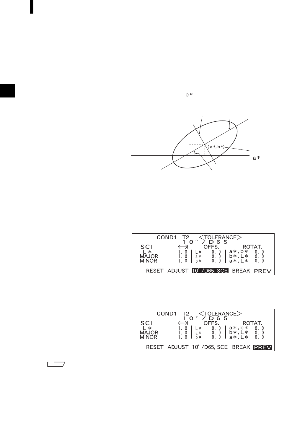
Setting Color Difference Tolerances
• Keeping B held down to left or right will cause the value to change continuously.
• “MAJOR” in the L*a*b* color space will be “a*” axis when “OFFS.” and “ROTAT.” on the “a*b*”
plane are “0” (ZERO).
• To change a value that has been
set, press C (MEAS. button) in
the screen where “
is displayed. This will take you to
the previous items, so change the
value.
↑ : <MEAS.>”
MINOR
If the measurement conditions (illuminant 2, observer, specular component mode,
8
etc.) are displayed, turn B to select it and press A to switch to the screen
that allows setting elliptical tolerances for illuminant 2. Set the desired elliptical
tolerances in the same way as in steps 6 and 7.
• Example when “*/I+E” is set for “MASK/GLOSS” and illuminant 2 is selected.
MAJOR
ROTAT.
OFFS.
E-58
Turn B to select “PREV”, then press A.
9
The <TARGET> screen will reap-
pear.
M
emo
Use of the optional Color Data Software “SpectraMagic” (Ver.3.2 or higher; excluded Ver.3.5) allows you
to set elliptical tolerances using CMC coefficients or automatically set them using the target colors and some
preset values.
Page 61

Setting Color Difference Tolerances
Clearing Tolerances
To change the tolerance type, it is necessary to clear the currently set tolerances.
To clear the currently set tolerances, follow the procedure given below:
[Setting Procedure]
<TARGET> screen
1. Turn B to select “TOLERANCE”, then press A.
The currently set tolerances will be dis-
played.
2. Turn B to select “RESET”, then press A.
A message confirming you whether to
clear the tolerances will appear.
3. Turn B to select “OK” or “CANCEL”, then press A.
• If “OK” is selected, the currently
set tolerances will be cleared, and
a screen that allows selection of
the tolerance type will appear.
If a color space that does not allow
setting of elliptical tolerances has
been selected, a screen that allows
setting of box tolerances will ap
pear automatically.
To make pass/fail judgment, it is
necessary to set tolerances again.
-
• If “CANCEL” is selected, clear-
ing of tolerances will be canceled
and the previous screen will reap
pear.
-
E-59
Page 62

Setting Color Difference Tolerances
E-60
Page 63

Chapter 3
Measurement
E-61
Page 64

Measurement
To perform measurement, you need to switch from a screen in which “BREAK” is displayed to the measurement screen.
To perform measurement, follow the procedure given below:
Note
• Prior to start of measurement, be sure to perform white calibration. For details, refer to “White Calibration” (page E-46).
• To measure color difference, it is necessary to set target colors first and then select the one to be used for measurement.
• For accurate measurement, make sure to keep measurement conditions (ambient temperature etc.) constant.
[Operating Procedure]
Turn B to select “BREAK”, then press A.
1
• Example for <COND1> screen.
• “T*” is the number of the color difference target data for the next
measurement. If nothing is selected, “T---” appears.
• “T*” does not appear if “defined in COND.” mode is selected.
Place the specimen measuring port to the specimen.
2
E-62
• If necessary, slide the viewfinder lever to check the position of the specimen.
Make sure that is displayed, then press C (MEAS. button).
3
The lamp will flash, measurement
will be taken, then the result will ap-
pear on the LCD.
• Example when “DIFF&ABS” is selected as the display mode.
Page 65

Measurement
M
emo
• Measurement will no longer be possible once the total number of target color data and measured data reaches 1700
(700 in the “defined in COND.” mode). In this case, delete some target color data or measured data.
• The navigation wheel and MEAS. button cannot be used for three seconds after the MEAS. button is pressed, if
“UV100%” has been set for “UV SETTING”, or for four seconds if “UV0%” or “ADJUSTED” has been set.
• If the Ganz coefficient is re-downloaded and overwritten after measurement when “WI, Tint Ganz” has been selected as the display mode, the measurement data will be replaced with the one that is calculated based on that
Ganz coefficient.
• If does not appear due to the auto power save function, this may be due the fact that it can take time to start
measurement after C is pressed.
E-63
Page 66

Displaying the Measurement Results
At the end of measurement, the measurement results will be displayed on the LCD according to the specified measurement condition. Typical measurement result screens are shown hereafter. To change LCD’s
display contents, change them in the corresponding <COND
Measurement Condition” (from page E-34).
Measured Data
The following screen appears if “DIFF&ABS” has been selected for “DISPLAY” mode.
Note
• Color difference will not be displayed if no target color has been selected.
• If the target mode is “linked to each data.”, you will not be able to view the color difference for measurement
data that uses the deleted color difference target data.
M
emo
“#####” will be displayed if the color difference data has two or more decimal places.
> screen. For details, refer to “Setting a
*
E-64
1 Ready to measure.
2 Currently selected <COND*> no.
3 Mask/gloss/UV at the time of measurement
4 Currently selected observer/illuminant
5 Currently selected measured data no.
6 Currently selected target color data no.
7 Measured data
8 Measurement date. For the year, only the lower two digits are displayed.
9 Displays the relative gloss value. If the gloss value exceeds 200, the screen will display
“G###” in place of the value.
0 Deletes the currently displayed measured data.
A Displays other measured data.
B Switches the screen page from one to another (when there are two pages or more).
C Switches to the <TARGET> screen for the currently selected no. (T*).
D Outputs the currently displayed measured data to the printer.
E Returns to the <COND*> screen.
F Appears if there is insufficient battery power when the instrument is powered by the bat-
tery. If appears, replace the batteries with new ones.
Page 67

Displaying the Measurement Results
Pass/Fail Judgment
The following screen appears if “PASS/FAIL” has been selected for “DISPLAY” mode and tolerances
have been set.
• When the result is “PASS”
1 Ready to measure.
2 Currently selected <COND*> no.
3 Mask/gloss/UV at the time of measurement
4 Currently selected observer/illuminant
5 Currently selected measured data no.
6 Currently selected target color data no.
7 PASS/FAIL judgment result.
8 Measurement date. For the year, only the lower two digits are displayed.
9 Displays the relative gloss value. If the gloss value exceeds 200, the screen will display
“G###” in place of the value.
0 Deletes the currently displayed measured data.
A Displays other measured data.
B Switches the screen page from one to another (when there are two pages or more).
C Switches to the <TARGET> screen for the currently selected no. (T*).
D Outputs the currently displayed measured data to the printer.
E Returns to the <COND*> screen.
F Appears if there is insufficient battery power when the instrument is powered by the bat-
tery. If appears, replace the batteries with new ones.
• When the result is “FAIL”
E-65
Page 68

Displaying the Measurement Results
Color Difference Graph
The following screen appears if “COLOR GRAPH” has been selected for “DISPLAY” mode. The
L*a*b* color difference value and the assessment message will be displayed in this screen regardless of
the color space selected for “COLOR SPACE” condition item. The data will be plotted in a color differ
ence graph with the selected target color as the origin.
(If “*/I+E” has been selected as specular component mode, only the graph will be displayed. Color difference value and assessment message will not be displayed.)
Note
• If no target color has been selected, no color difference will be displayed and the graph will be blank.
• If the target mode is “linked to each data.”, you will not be able to view the color difference for measurement
data that uses the deleted color difference target data.
M
emo
“#####” will be displayed if the color difference data has two or more decimal places.
-
E-66
1 Ready to measure.
2 Currently selected <COND*> no.
3 Mask/gloss/UV at the time of measurement
4 Currently selected target color data no.
5 Measured data.
6 Color difference graph
7 Currently selected measured data no.
8 Currently selected observer/illuminant
9 Measurement date. For the year, only the lower two digits are displayed.
0 Displays the relative gloss value. If the gloss value exceeds 200, the screen will display
“G###” in place of the value.
A Deletes the currently displayed measured data.
B Displays other measured data.
C Switches the screen page from one to another (when there are two pages or more).
D Switches to the <TARGET> screen for the currently selected no. (T*).
E Outputs the currently displayed measured data to the printer.
F Returns to the <COND*> screen.
G Appears if there is insufficient battery power when the instrument is powered by the bat-
tery. If appears, replace the batteries with new ones.
Page 69

• Color difference graph
H L* axis (color difference graph)
I a* axis (color difference graph)
J b* axis (color difference graph)
K Measuring point
L Scale for each axis
M Specified box tolerances
N Position of target color
Displaying the Measurement Results
Spectral Reflectance Graph
The following screen appears if “SPECT. GRAPH” has been selected for “DISPLAY” mode.
1 Ready to measure.
2 Currently selected <COND*> no.
3 Spectral reflectance graph
4 Position of the currently selected wavelength
5 Mask/gloss/UV at the time of measurement
6 Currently selected measured data no.
7 Currently selected wavelength
8 Spectral reflectance at the currently selected wavelength data
9 Measurement date. For the year, only the lower two digits are displayed.
0 Displays the relative gloss value. If the gloss value exceeds 200, the screen will dis-
play “G###” in place of the value.
A Select the wavelength in the spectral reflectance graph.
Turn B to select and press A to switch to . The desired
wavelength can be selected by turning B.
E-67
Page 70

Displaying the Measurement Results
B Deletes the currently displayed measured data.
C Displays other measred data.
D Outputs the currently displayed measured data to the printer.
E Returns to the <COND*> screen.
F Appears if there is insufficient battery power when the instrument is powered by the
battery. If
appears, replace the batteries with new ones.
Assessments
The following screen appears if “ASSESSMENTS” has been selected for “DISPLAY” mode and tolerances have been set.
M
emo
“#####” will be displayed if the color difference data has two or more decimal places.
• Displaying Assessment by Box Tolerance
E-68
1 Ready to measure.
2 Currently selected <COND*> no.
3 Mask/gloss/UV at the time of measurement
4 Currently selected observer/illuminant
5 Currently selected measured data no.
6 Currently selected target color data no.
7 Color Difference from the target, result of PASS/FAIL judgment and message indicating
the deviation direction
8 Measurement date. For the year, only the lower two digits are displayed.
9 Displays the relative gloss value. If the gloss value exceeds 200, the screen will display
“G###” in place of the value.
0 Deletes the currently displayed measured data.
A Displays other measured data.
B Switches the screen page from one to another (when there are two pages or more).
C Switches to the <TARGET> screen for the currently selected no. (T*).
D Outputs the currently displayed measured data to the printer.
E Returns to the <COND*> screen.
F Appears if there is insufficient battery power when the instrument is powered by the bat-
tery. If appears, replace the batteries with new ones.
Page 71

• Displaying Assessment by Elliptical Tolerance
1 Ready to measure.
2 Currently selected <COND*> no.
3 Mask/gloss/UV at the time of measurement
4 Currently selected observer/illuminant
5 Currently selected measured data no.
6 Currently selected target color data no.
7 Color Difference from the target, result of PASS/FAIL judgment and message indicating
the deviation direction
8 Measurement date. For the year, only the lower two digits are displayed.
9 Displays the relative gloss value. If the gloss value exceeds 200, the screen will display
“G###” in place of the value.
0 Deletes the currently displayed measured data.
A Displays other measured data.
B Switches the screen page from one to another (when there are two pages or more).
C Switches to the <TARGET> screen for the currently selected no. (T*).
D Outputs the currently displayed measured data to the printer.
E Returns to the <COND*> screen.
F Appears if there is insufficient battery power when the instrument is powered by the bat-
tery. If appears, replace the batteries with new ones.
Displaying the Measurement Results
E-69
Page 72

Displaying the Measurement Results
Switching the Display Contents of the Measurement Results
In the measurement screen that appears at the end of measurement, the following data will be displayed
according to the settings made in the <FILE> screen. The display contents can also be changed.
M
emo
Selecting “DISP” by turning B in a measurement screen in which “DISP” is displayed and then pressing A
will allow you to switch the display contents of the measurement results.
Settings in <FILE> Screen
Display Mode (P. E-38) Color Space (P. E-39)
L*a*b*, L*C*h,
XYZ, Yxy etc.
DIFF&ABS
(Color difference &
absolute value)
PASS/FAIL
COLOR GRAPH
(Color difference graph)
WI, YI etc.
Munsell, density
L*a*b*, L*C*h,
XYZ, Yxy etc.
WI, YI etc.
Munsell, density
L*a*b* only
Specular component (P. E-35)
I + E
SCI or SCE
I + E
SCI or SCE
I + E
SCI or SCE
I + E
SCI or SCE
I + E
SCI or SCE
Other Conditions
Only illuminant 1 is set.
Both illuminants 1 and 2
are set.
Only illuminant 1 is set.
Both illuminants 1 and 2
are set.
Japanese only
SPECT. GRAPH
(Spectral graph)
ASSESSMENT
L*a*b*, L*C*h only
I + E
SCI or SCE
Box tolerance
Elliptical tolerance
Note
• Metamerism index is displayed only if L*a*b* or L*C*h is selected as the color space.
• “Deviation A” indicates that the direction in relation to the target color is displayed, irrespective of whether the
results are PASS or FAIL. “Deviation B” indicates that “PASS” is displayed when the result is PASS and the
direction is displayed only when the result is FAIL.
• Items enclosed by are not displayed in English.
• If the display mode is set to “COLOR GRAPH” and the MASK/GLOSS is set to “*/I+E”, the system will display
graphs for light source #1 only. If you set the system to use two different sources, only graphs for source #1 will
be shown.
E-70
Page 73

Displaying the Measurement Results
Screen Switching
Measurement Screen 1 Measurement Screen 2 Measurement Screen 3
Color difference, absolute value
Color difference, absolute value
Metamerism index (MI)*
Metamerism index (MI)*
Color difference, absolute value
Color difference, absolute value
Absolute value only
PASS or FAIL
PASS or FAIL
PASS or FAIL
PASS or FAIL
Absolute value only
Color difference graph
Color difference graph, color difference, absolute value
Color difference graph, color difference, deviation A
Spectral graph, reflectance of
selected wavelength
Color difference only
Color difference only
Color difference, absolute value
Color difference only
Metamerism index (MI), color difference & absolute value
Color difference only
Metamerism index (MI), color difference & absolute value
Color difference, absolute value
Color difference, absolute value
Color difference, absolute value
Color difference, absolute value
Absolute value only
Absolute value only
Absolute value only
Metamerism index (MI), absolute value
Color difference, deviation B
Color difference, deviation A, PASS or FAIL
Color difference, deviation A, PASS or FAIL
Color difference, absolute value
Color difference, absolute value
Color difference, absolute value
* Metamerism index (MI) is displayed only if L*a*b* or L*C*h is selected as the color space.
E-71
Page 74

Displaying the Measurement Results
Deleting Measured Data
There are two methods of deleting measured data. One is to delete the data items displayed on the LCD
one by one. The other is to delete all the data items for the selected measurement condition (COND1 to
COND6).
Deleting Data One by One
Data currently displayed on the LCD can be deleted.
This can be done in the measurement screen.
1. Turn B to select “D”, and then press A.
“D” will change to “E”.
2. Turn B to select the data to be deleted, and then press A.
“E” will return to “D”.
• Keeping B held down to left or right will cause the preset data No. (No.
3. Turn B to select “DEL”, and then hold down A for more than one second.
A confirmation message will appear.
4. To delete the data, select “OK” with B and press A. The selected data will be
deleted, and the data below the delected one will scroll up.
To cancel deletion, select “CANCEL” with B and press A. Deletion of the data
will be canceled, and the previous screen will reappear.
) to change continuously.
*
E-72
Page 75

Displaying the Measurement Results
Deleting All Data At Once
All the data items for the selected measurement condition (COND1 to COND6) can be deleted at once.
Note
• Never turn OFF the instrument while global deletion is in progress.
• Should the instrument be turned OFF during global deletion, the measured data for all the measurement conditions (COND1 to COND6) as well as for all the tasks will be deleted.
However, measurement conditions (e.g. color space) and target color data will be retained.
This can be done in the <INITIAL> screen.
1. Turn B to select the measurement condition (COND
is to be deleted globally, then press A.
2. Turn B to select “DATA DELETE”, then press A.
A confirmation screen will appear.
• “T*” does not appear if “defined in COND.” mode is selected.
3. Turn B to select “OK”, then press A.
All the measured data will be globally
deleted.
) of which all the measured data
*
During global deletion, the amount of
deleted measured data will be displayed
in a percentage.
When data deletion is complete, the
<COND*> screen will reappear.
M
emo
To cancel deletion, select “CANCEL”
and press
be canceled.
• “T*” does not appear if “defined in COND.” mode is selected.
A. Global deletion will
E-73
Page 76

Displaying the Measurement Results
Abbreviations on LCD Display
To facilitate the user’s understanding of various types of information displayed on the instrument’s LCD, the
following abbreviations are commonly used.
• For notation of values to be set in each setting screen (e.g. measurement conditions), refer to the description
given in the corresponding operating procedure.
Screen/Item Notation Meaning
<FILE> screen
Screens appearing during
calibration
<TARGET> screen
<TOLERANCE> screen
Screens in following Display mode
• “DIFF&ABS”
• “PASS/FAIL”
• “COLOR GRAPH”
• “SPECT. GRAPH”
Mask (measurement area)
Gloss (spectral component)
UV adjustment
M MAV
S SAV
I+E
100
0
ADJ
SCI (specular component included) and
SCE (specular component excluded)
UV 100%
UV 0% (no specular component)
UV adjustment required
Screens in following Display mode
• “DIFF&ABS”
• “PASS/FAIL”
Color space, colorimetric
data
CMC1 CMC1:1
CMC2 CMC2:1
L4 L for CIE94
C4 C for CIE94
H4 H for CIE94
E94 E for CIE94
LC L for CMC1:1 or CMC2:1
CC C for CMC1:1 or CMC2:1
HC H for CMC1:1 or CMC2:1
Tw Tint value
E00 E when CIE00 is set
E-74
Page 77

Displaying the Measurement Results
Measurement Results for “linked to each data.”
This instrument can set multiple target color data numbers and select one of those for displaying the results for the color difference. It can also easily switch the selected target color number using the navigation wheel. The “defined in COND.” target mode can use these functions to calculate multiple color
differences for measurement data, and make pass/fail judgments based on this.
However, the pass/fail judgment is based on a standard color difference setting for the selected target
color data number and the color difference. The differences between the target color data and the color
difference is not always standard.
The other target mode supported by this instrument, “linked to each data.”, can store the target color data
number with the selected measurement data and display the results using the associated target color data
number. In addition to absolute values, it can also be used for general color differences.
This section describes how the results are affected when using “linked to each data.” target mode and the
specified target color data has been changed or deleted. It also compares the difference to the results dis
played for “defined in COND.” target mode.
When the Color Difference Target Data No. has Been Changed
When “T” is selected in the measurement results screen, the target color screen will be changed to the
currently selected number to be used for next measurement. The navigation wheel can also be used in
this screen to recall a target color number that has been stored in the instrument’s memory. If “BREAK”
is selected in the target color data screen, you can revert to the originally selected target color number.
For details, see “Switching between the Measured Data screen and the <TARGET> screen” on page E-
49.
-
Select and then press A, the <TARGET> screen
is displayed. It shows the target color data which number
is currently selected and is used for next measurement.
Select D, press A and then turn B to the
left or right, it can be switched the target color data
number.
In “linked to each data.” mode, the measured data is calculated with the target data which is selected at the time
of measurement and the results are displayed.
Select “BREAK” and then press A, the display return to the measurement screen.
In “defined in COND.” mode, the measured data
is recalculated with the new selected target color
number’s data and the results are displayed.
E-75
Page 78

Displaying the Measurement Results
When the Target Color Data No. has Been Deleted
If the target color data for a number is deleted, the target color for data to which that number was associated is set to that of the next highest number. The target color number is reset to that of the number for
which there is a target color data number.
With “linked to each data.” target-mode, the measured data is saved with target color number that was
specified for it at the time of measurement. If the number for the target color that was set at the time of
measurement is deleted, the link between the data and target color data number is cut when the number
is deleted. The measurement data is saved with information that states that there is no target color for that
data, “T---” is displayed for the target color, and “-----” for the color difference and pass/fail judgment.
In addition, no points appear on the graph.
With “defined in COND.” the color difference and pass/fail judgments for the reset target color data and
its data are recalculated based on the associated color difference.
In “linked to each data.” mode, the measured data is calcu-
Select and then press A , the <TARGET> screen
is displayed. It shows the target color data which number
is currently selected and is used for next measurement.
lated with the target data which is selected at the time of
measurement. Because the target color data is deleted,
“T- - -” is displayed on the screen as the target color data
number, and the no color difference results are displayed
(“- - - - -” is displayed as the color difference results).
In the <TARGET> screen that shows the target color data
which you want to delete, select “DEL” and then press
A, the <TARGET DELETE> screen is displayed. In
the screen, select “T
the target color data which the target color data number is
” will be deleted.
“T
*
If a number for target color data is deleted, the target color is set to the next target color, but set as the target color of the
deleted number.
* In the example above, target color T2 has been set to number T1.
DELETE” and then press A,
*
Select “BREAK” and then press A, the display
return to the measurement screen.
In “defined in COND.” mode, the measured data is
recalculated with the new selected target color
number's data and the results are displayed.
E-76
Page 79

Chapter 4
Other Functions
E-77
Page 80

Measuring the Average
When taking measurements or setting target colors, more accurate data can be obtained if the averaging
function is used.
The following two averaging functions are available.
• Manual Averaging: When the color of the specimen is not uniform, measurements are performed at
different positions on the specimen and then the average of the measured reflect
ance data is calculated. This gives the average data of the entire specimen.
• Auto Averaging: Specified number of measurement are repeated at the same position on the speci-
men and then the average of the measured spectral reflectance data is calculated.
This will improve the accuracy of the measured data.
These two functions can be used in combination. In this case, it is necessary to make settings for both
auto and manual averaging. For details, refer to “Setting a Measurement Condition” (from page E-34).
Note
For average measurement, the average of the measured spectral reflectance data is calculated first, then colorimetric data is calculated based on that calculated average. Thus, the result may not match the average of colorimetric data.
Manual Averaging
This method is used when the color of the specimen is not uniform. Measurements are performed at different positions on the specimen and then the average of the measured reflectance data is calculated, to
obtain the average data of the entire specimen.
Set the number of measurements to be performed and the standard deviation, and then start measurement.
-
Note
Before starting manual averaging, make sure that the number of measurements to be performed and standard
deviation are set. For details, refer to “Setting an Measurement Condition” (from page E-34).
[Setting Procedure]
This operation can be started from a screen in which “BREAK” is displayed.
Make sure that “BREAK” is highlighted, then press A.
1
Turn B to select “BREAK”,
if it is not highlighted.
• Example when “COND1” is selected.
E-78
Page 81

Measuring the Average
Place the specimen measuring port to the specimen to be measured, and then
2
press C (MEAS. button).
If 2 is set for “MANUAL AVG.
TIMES” or if 3 or a higher value is
set and the standard deviation is not
below the specified one, place the
specimen measuring port to the next
place and then press
button).
When the specified number of meas-
urements has been completed or the
standard deviation drops below the
specified one, the averaging result
will be displayed on the LCD.
C (MEAS.
• The number of completed measurements including the one currently in progress and standard deviation will be displayed during
measurement.
M
emo
• To exit manual averaging and display the results before the specified number of measurements is completed or
before the specified standard deviation is reached, press A.
• If does not appear due to the auto power save function, this may be due the fact that it can take time
to start measurement after C is pressed.
E-79
Page 82

Measuring the Average
Auto Averaging
Measurement is repeated the specified number of times in the same position on the specimen and then
the average of the measured reflectance data is calculated. This will improve the accuracy of the meas
ured data.
Set the number of measurements to be performed and the standard deviation, and then start measurement.
Note
Before starting auto averaging, make sure that the number of measurements to be performed is set. For details,
refer to “Setting a Measurement Condition” (from page E-34).
[Setting Procedure]
This operation must be started from a screen in which “BREAK” is displayed.
Make sure that “BREAK” is highlighted, then press A.
1
Turn B to select “BREAK”,
if it is not highlighted.
-
• Example when “COND1” is selected
Place the speimen measuring port to the specimen, and then press C (MEAS.
2
button).
• Take care to keep the instrument still during measurement.
The number of lamp flashing will be
highlighted during auto averaging.
When the specified number of meas-
urements has been completed, the
averaging result will be displayed on
the LCD.
E-80
M
emo
If does not appear due to the
auto power save function, this may
be due the fact that it can take time to
start measurement after C is
pressed.
Page 83

Pass/Fail Judgment for Color Difference
This instrument allows you to set tolerances for the measured color difference, to make pass/fail judgment.
Two kinds of pass/fail judgment methods are available. One is based on the specified box tolerances, and
the other is based on the specified elliptical tolerances.
In “linked to each data.” mode, the number of the target color data selected at the time of measurement
or the measured data are passed/failed based on the tolerances.
If the target color data has been deleted, the color difference displayed for that color target and based on
the tolerances for the color target cannot be performed. In addition, if other target color data is selected,
recalculations and pass/fail judgments cannot take place.
Pass/Fail Judgment Based on Box Tolerances
If the measured color difference is outside the specified tolerances, it will be highlighted to indicate that
the pass/fail judgment result is FAIL. Both + and - tolerances can be set for each target color.
To perform pass/fail judgment based on the specified box tolerances, follow the procedure given below:
Note
To use this function, make sure that the target color to be used is set.
[Setting Procedure]
<COND*> screen
Turn B to select “TARGET”, then press A.
1
•“T*” does not appear if “defined in COND.” mode is selected.
Turn B to select “D”, then press A.
2
“D” will change to “E”.
Turn B to select the desired target color no. (T*), then press A.
3
“E” will return to “D”.
• Keeping B held down to left or right will cause the target color No. to change continuously.
E-81
Page 84

Pass/Fail Judgment for Color Difference
Turn B to select “TOLERANCE”, then press A.
4
The currently set tolerances will be
displayed.
If they are satisfactory, turn B to select “BREAK”, then press A.
5
The measurement screen will ap-
pear.
Place the specimen measuring port to the specimen, and then press C (MEAS. button).
6
<If “DIFF&ABS” has been selected as the display mode>
Values for the items that have failed
will be highlighted.
• “#####” will be displayed if the color difference data has two or more decimal places.
<If “PASS/FAIL” has been selected as the display mode>
“FAIL” will be displayed and high-
lighted if any of the items has failed,
and “PASS” will be displayed if all
the items have passed.
• Here the judgment result is “PASS”, and the results are displayed as shown above according to the conditions when the data was measured.
E-82
• Here the judgment result is “FAIL”, and the results are displayed as shown above according to the conditions when the data was measured.
Page 85

Pass/Fail Judgment for Color Difference
M
emo
• If “PASS/FAIL” has been selected as the display mode, “PASS” will be displayed only when all the items have
passed.
• If “DIFF/ABS” has been selected as the display mode, the values for the items which have failed will be highlighted
• If a color difference has not been set, when the target mode is “linked to each data.”, and the target color data
number set at the time of measurement is deleted, “----” appears instead of “PASS/FAIL”.
• If does not appear due to the auto power save function, this may be due the fact that it can take time to
start measurement after C is pressed.
Pass/Fail Judgment Based on Elliptical Tolerances
This function is used to judge whether the measured color difference is within the elliptical tolerances specified
for the target color.
To perform pass/fail judgment based on the specified elliptical tolerances, follow the procedure given below:
Note
• To use this function, make sure that elliptical tolerances are set.
• “PASS” or “FAIL” is displayed only if “PASS/FAIL” has been selected as the display mode.
[Setting Procedure]
<COND*> screen
Turn B to select “TARGET”, then press A.
1
• “T*” does not appear if “defined in COND.” mode is selected.
Turn B to select “D”, then press A.
2
“D” will change to “E”.
Turn B to select the desired target color no. (T*), then press A.
3
“E” will return to “D”.
• Keeping B held down to left or right will cause the target color No. to change continuously.
E-83
Page 86

Pass/Fail Judgment for Color Difference
Turn B to select “TOLERANCE”, then press A.
4
The currently set tolerances will be
displayed.
If they are satisfactory, turn B to select “BREAK”, then press A.
5
The measurement screen will ap-
pear.
Place the specimen measuring port to the specimen, and then press C (MEAS.
6
button).
If “PASS/FAIL” has been selected
as the display mode, a judgment will
be made to check whether the meas
urement result is within the specified
ellipse, and “PASS” or “FAIL” will
be displayed accordingly.
M
emo
• If “PASS/FAIL” has been selected as the display mode, “PASS” will be displayed only when the color difference
between the measured value and the target color is within each specified elliptical tolerance (up to four tolerances).
• If “DIFF/ABS” has been selected as the display mode, the measured results will not be highlighted even if they
are “FAIL”.
• If a color difference has not been set, when the target mode is “linked to each data.”, and the target color data
number set at the time of measurement is deleted, “----” appears instead of “PASS/FAIL”.
• If does not appear due to the auto power save function, this may be due the fact that it can take time to
start measurement after C is pressed.
-
• Example when the result is “PASS”.
• Example when the result is “FAIL”.
E-84
Page 87

Assessments
This instrument allows assessment of measurement results by simultaneously displaying the direction of
tint deviation from the target color, the color difference from the target color and pass/fail judgment
based on the specified tolerances.
Note
To use this function, make sure that color difference tolerances are set in advance.
Assessment by Box Tolerances
[Setting Procedure]
<COND*> screen
Turn B to select “TARGET”, then press A.
1
Turn B to select “D”, then press A.
2
“D” will change to “E”.
Turn B to select the desired target color no. (T*), then press A.
3
“E” will return to “D”.
• Keeping B held down to left or right will cause the target color No. to change continuously.
Turn B to select “TOLERANCE”, then press A.
4
The currently set tolerances will be
displayed.
E-85
Page 88

Assessments
If they are satisfactory, turn B to select “BREAK”, then press A.
5
The measurement screen will ap-
pear.
Place the specimen measuring port to the specimen, and then press C (MEAS.
6
button).
The color difference from the target color, pass/fail judgment result based on the specified box tolerances
and direction of tint and brightness deviation will be displayed.
• The color space to be used as the assessment axis differs depending on the selected color space.
When “L*C*h, E”, “L*C*h, CMC1:1”, “L*C*h, CMC2:1” or “L*C*h, CIE94” is selected, assessment will be made based on the direction of tint and lightness deviation and color difference from the
target color in the L*C*h axis.
When a color space other than those given above is selected, assessment will be made based on the
direction of tint and lightness deviation and color difference from the target color in the L*a*b* axis.
M
emo
• Assessment results differ as shown in the table below depending on the type of specified color difference tolerances and pass/fail judgment result.
Type
Box
tolerance
Elliptical
tolerance
Specular
component
I+E
SCI or SCE
I+E
SCI or SCE
Displayed value
Color difference
E*
Color difference
E*
Color difference No judgment Measured value, with message to the right
E*
Pass/fail
judgment
PASS Measured value, with “PASS” to the right
FAIL
PASS Measured value, with “PASS” to the right
FAIL
PASS Measured value, with “PASS” to the right.
FAIL
PASS Measured value, with “PASS” to the right
FAIL
PASS Measured value, with “PASS” to the right
FAIL
Highlighted measured value, with highlighted
message to the right
Highlighted measured value, with highlighted
“FAIL” to the right
Highlighted measured value, with highlighted
“FAIL” and message to the right
Highlighted measured value, with highlighted
“FAIL” to the right
Measured value, with highlighted “FAIL” to the
right
Display content
E-86
Page 89

Assessments
• The following deviation directions can be indicated by a message.
L*: LIGHTER/DARKER
a*: +RED (stronger red)/-RED (weaker red) / +GREEN (stronger green)/-GREEN (weaker green)
b*: +YELLOW (stronger yellow)/-YELLOW (weaker yellow) / +BLUE (stronger blue)/-BLUE (weak-
er blue)
C*: DULLER/VIVID
H*: +RED (stronger red)/+YELLOW (stronger yellow) / +GREEN (stronger green)/+BLUE (stronger
blue)
For E*, only the pass/fail judgment result will be displayed by “PASS” or “FAIL”.
Note
• If color difference tolerances have not been specified, pass/fail judgment result (“PASS” or “FAIL”) will not
be displayed.
• If no color target has been selected, the tint and brightness deviation direction and color difference will not be
displayed.
• In the case of L*C*h, “-----” will be displayed for H* if “C*” value of the color target or measured value is
excessively low.
• No message may appear if the color difference is excessively small.
Assessment by Elliptical Tolerances
[Setting Procedure]
<COND*> screen
Turn B to select “TARGET”, then press A.
1
Turn B to select “D”, then press A.
2
“D” will change to “E”.
Turn B to select the desired target color no. (T*), then press A.
3
“E” will return to “D”.
• Keeping B held down to left or right will cause the target color No. to change continuously.
E-87
Page 90

Assessments
Turn B to select “TOLERANCE”, then press A.
4
The currently set tolerances will be
displayed.
If they are satisfactory, turn B to select “BREAK”, then press A.
5
The measurement screen will ap-
pear.
Place the specimen measuring port to the specimen, and then press C (MEAS.
6
button).
The color difference, direction and amount of tint and brightness deviation from the target color will be dis-
played. In addition, on the right of “ E*” value, a pass/fail judgment result made based on the specified
elliptical tolerances will be displayed.
E-88
• The color space to be used as the assessment axis differs depending on the selected color space.
When “L*C*h, E”, “L*C*h, CMC1:1”, “L*C*h, CMC2:1” or “L*C*h, CIE94” is selected:
Assessment will be made based on the direction of tint and lightness deviation and color difference
from the target color in the L*C*h axis. When a color space other than those given above is selected,
assessment will be made based on the direction of tint and lightness deviation and color difference
from the target color in the L*a*b* axis.
M
emo
• Assessment results differ as shown in the table in page E-84 depending on the type of specified color difference
tolerances and pass/fail judgment result.
Page 91

Assessments
Type
Box
tolerance
Elliptical
tolerance
Specular
component
I+E
SCI or SCE
I+E
SCI or SCE
Displayed value
Color difference PASS Measured value, with “PASS” to the right
E* FAIL
Color difference PASS Measured value, with “PASS” to the right
E* FAIL
Color difference
E*
Color difference No judgment Measured value, with message to the right
E*
Pass/fail
judgment
Highlighted measured value, with highlighted
message to the right
Highlighted measured value, with highlighted
“FAIL” to the right
PASS Measured value, with “PASS” to the right.
FAIL
PASS Measured value, with “PASS” to the right
FAIL
PASS Measured value, with “PASS” to the right
FAIL
Highlighted measured value, with highlighted
“FAIL” and message to the right
Highlighted measured value, with highlighted
“FAIL” to the right
Measured value, with highlighted “FAIL” to the
right
Display content
• The following deviation directions can be indicated by a message.
L*: LIGHTER/DARKER
a*: +RED (stronger red)/-RED (weaker red)/+GREEN (stronger green)/-GREEN (weaker green)
b*: +YELLOW (stronger yellow)/-YELLOW (weaker yellow)/BLUE (stronger blue)/-BLUE (weaker blue)
C*: DULLER/VIVID
H*: +RED (stronger red)/+YELLOW (stronger yellow/+GREEN (stronger green)/+BLUE (stronger blue)
The pass/fail judgment made based on the specified elliptical tolerances will be displayed by “PASS” or “FAIL”
on the right of
“ E*”.
Note
• If color difference tolerances have not been specified, pass/fail judgment result (“PASS” or “FAIL”) will not
be displayed.
• If no color target has been selected, the tint and brightness deviation direction and color difference will not be
displayed.
• No message may appear if the color difference is excessively small.
E-89
Page 92

Connecting to an External Device
Connecting a PC or printer to the external output terminal on the instrument allows the transfer of data
between the instrument and PC or printing of the measurement results.
Connecting a Personal Computer
Connecting a PC (PC-AT compatible) to the instrument with a RS-232C cable will allow uploading the
data stored in the instrument’s memory to the PC or downloading data from the PC to the instrument.
When connecting this instrument to the PC, use of the optional Color Data Software “SpectraMagic NX”
(CM-S100w) is recommended.
M
emo
When the instrument is connected to the PC, make sure that the instrument is set in remote mode. Remote mode allows the following functions:
1. Outputting measured data and target color data to the PC
2. Downloading target data from the PC
3. Downloading tasks
For details, refer to “Switching to Remote Mode” (page E-89).
Note
• When connecting, make sure that the connectors are correctly oriented and fastened securely with screws.
• Before connecting, make sure that the power to both the instrument and PC is turned OFF.
• When disconnecting the cable, be sure to grip the plug or connector and pull it. Do not pull on or forcibly bend
the cable.
• Do not touch the connector terminals with your hand. Doing so may cause them to get dirty or apply excessive
force to them.
• Make sure that the cable has a sufficient length. Tensioning the cable may cause connection failure or wire
breakage.
• When using a cable other than the one supplied as the standard accessory, make sure that the cable conforms
to “RS-232C Pin Assignment and Cable Wiring Diagram” (page E-89). If it does not conform, a malfunction
may occur or incorrect data may be transferred between the instrument and PC.
Communication Parameters
Item Setting
Baud rate 9600 bps
Character bits 8 bits
Parity None
Stop bits 1 bit
SIP/SOP Connections
• Accessories equipment connected the analog and digital interfaces must be certified to the respective
IEC standards (i.e. IEC 950 for data processing equipment).
• Furthermore all configurations shall comply with the system standard IEC 10101-1. Everybody who
connects additional equipment to the signal input part or signal output part configures a electrical
equipment for measurement system, and is therefore, responsible that the system complies with the re
quirements of the system standard (IEC 10101-1. If in doubt, consult the technical services department
or your local representative).
E-90
-
Page 93

RS-232C Pin Assignment and Cable Wiring Diagram
Connecting to an External Device
Instrument
Personal Computer
(For D-sub, 9-pin)
5
4321
18
Pin No.
Signal
RXD
2
TXD
3
GND
5
RTS
7
CTS
8
9768
Signal
RXD
TXD
GND
RTS
CTS
Pin No.
2
3
5
7
8
Switching to Remote Mode
To transfer data between the instrument and the PC, the instrument must be switched to remote mode.
To switch to remote mode, follow the procedure given below.
[Setting Procedure]
Make sure that power to the instrument is turned OFF.
1. Connect the instrument to the PC with the RS-232C cable.
2. Turn the power ON.
• When the power is turned ON for the
first time, the <INITIAL> screen will
appear.
• Normally, the screen displayed just
before the power was turned OFF will
appear, so turn the navigation wheel
to display the <INITIAL> screen.
E-91
Page 94

Connecting to an External Device
3. Turn B to select “MENU”, then press A.
The <MENU> screen will appear.
4. Turn B to select “REMOTE”, then press A.
The <REMOTE> screen will appear.
M
emo
To return to the <MENU> screen, press A.
E-92
Page 95

Connecting to an External Device
Outputting to a Printer
Connecting the instrument to a printer with a printer cable allows printing the measured data or the color
difference target data stored in the instrument’s memory. Two printing methods are available. One is to
print automatically each time measurement is taken (this is called “Auto Print”; measured data only), and
the other is to print the currently displayed measured data, pass/fail results and color difference target
data.
M
emo
If “SPECT.GRAPH” is selected as the display mode, the spectral reflectance data of displayed data in each screen;
the measured data in the measured data screen or the color difference target data in the <TARGET> screen, will be
printed. If “COLOR GRAPH” is selected, the color difference and absolute data will be printed. If “PASS/FAIL” is
selected, either “PASS” (or “FAIL”) or the color difference and absolute data will be printed.
Note
• When connecting the connectors, make sure that they are correctly oriented and fastened securely with screws.
• Before connecting, make sure that the power to both the instrument and printer is turned OFF.
• When disconnecting the cable, be sure to grip the plug or connector and pull it. Do not pull on or forcibly bend
the cable.
• Do not touch the connector terminals with your hands, allow them to get dirty or apply excessive force to them.
• Make sure that the cable has a sufficient amount of slack. Pulling the cable taut may cause connection failure
or wire breakage.
• The instrument and printer must be connected using a printer cable that is wired as shown in “Printer Cable
Wiring Diagram” (page E-92).
Communication Parameters
Item Setting
Baud rate 9600 bps
Character bits 8 bits
Parity None
Stop bits 1 bit
Flow control RTS/CTS
Applicable Printers: DPU-H245AS-A03 *serial connection/metric screw type (Seiko Instruments
Inc.)
In addition to the above printer, printers that meet the following specifications can be used.
Item Specifications
Number of print lines 27 or more lines, Data input: RS-232C
Data control BUSY
Baud rate 9600
Character bits 8 bits
Parity None
Stop bits 1 bit
Basic function CR (0DH) carriage return
E-93
Page 96

Connecting to an External Device
Printer Cable Wiring Diagram
• For D-sub, 9pin
Instrument
18
Printer
(For D-sub, 9-pin)
5
4321
9768
Pin No. Signal
3
TXD
5
GND
8
CTS
Signal Pin No.
DATA
GND
BUSY
3
5
8
• For D-sub, 25pin
Instrument
18
Pin No. Signal
3
TXD
5
GND
8
CTS
Printer
(For D-sub, 25-pin)
Signal Pin No.
DATA
BUSY
GND
2
5
7
Auto Print
If Auto Print has been setup beforehand, the measurement data can be printed as each measurement is
made.
Note
The instrument and printer must be connected using a printer cable that is wired as shown in “Printer Cable Wiring Diagram” (page E-92).
[Procedure]
Make sure that power to the instrument is turned OFF.
1. Connect the instrument to the printer with a printer cable.
E-94
Page 97

2. Turn the power ON.
3. Turn B to select “MENU”, then press A.
4. Turn B to select “AUTO PRINT”, then press A.
Connecting to an External Device
5. Turn B to select “ON”, then press A.
Measured data will be printed automati-
cally each time measurement is taken.
Printing Measured Data
M
emo
To print measured data, make sure that the instrument is connected to the printer with a printer cable.
Note
• The instrument and printer must be connected using a printer cable that is wired as shown in “Printer Cable
Wiring Diagram” (page E-92).
• Before connecting, make sure that the power to both the instrument and printer is turned OFF.
E-95
Page 98

Connecting to an External Device
[Procedure]
This operation must be started from a screen in which measured data is displayed.
1. Turn B to select “D”, then press A.
“D” will change to “E”.
2. Turn B to select the measured data to be printed, then press A.
“E” will return to “D”.
• Keeping B held down to left or right will cause the measured data No. (No.
3. Turn B to select “ ”, then press A.
M
emo
• If “COLOR GRAPH” has been selected as the display mode, only numeric data will be printed.
• If “PASS/FAIL” has been selected as the display mode, either pass/fail judgment results or color difference
and absolute data will be printed.
• If “SPECT.GRAPH” has been selected as the display mode, spectral reflectance data will be printed.
) to change continuously.
*
• Print Example 1
Display mode: “ABS. & DIFF.”
E-96
Page 99

• Print Example 2
Display mode: “SPECT.GRAPH”
Connecting to an External Device
• Print Example 3
Display mode: “COLOR GRAPH”
E-97
Page 100

Connecting to an External Device
Printing Color Difference Target
M
emo
To print color difference target data, make sure that the instrument is connected to the printer with a printer cable.
Note
• The instrument and printer must be connected using a printer cable that is wired as shown in “Printer Cable
Wiring Diagram” (page E-92).
• Before connecting, make sure that the power to both the instrument and printer is turned OFF.
[Procedure]
This operation must be started from the <TARGET> screen.
1. Turn B to select “D”, then press A.
“D” will change to “E”.
2. Turn B to select the color difference target data to be printed, then press A.
“E” will return to “D”.
• Keeping B held down to left or right will cause the color difference target data No. (T
continuously.
3. Turn B to select “ ”, then press A.
M
emo
• If “SPECT.GRAPH” has been selected as the display mode, spectral reflectance data will be printed.
• If a mode other than “SPECT.GRAPH” has been selected as the diaplay mode, only colorimetric value data
will be printed.
) to change
*
E-98
 Loading...