


Service Manual
[General]
CF5001

CF5001 Ver.1.0 Sep. 2003 CONTENTS
CONTENTS
SAFETY AND IMPORTANT WARNING ITEMS. . . . . . . . . . . . . . . . . . . . . . . . . . . . . . . . . . . . . . . . . . . . . S-1
IMPORTANT NOTICE . . . . . . . . . . . . . . . . . . . . . . . . . . . . . . . . . . . . . . . . . . . . . . . . . . . . . . . . . . . . . . . S-1
DESCRIPTION ITEMS FOR DANGER, WARNING AND CAUTION . . . . . . . . . . . . . . . . . . . . . . . . . . . . S-1
SAFETY WARNINGS . . . . . . . . . . . . . . . . . . . . . . . . . . . . . . . . . . . . . . . . . . . . . . . . . . . . . . . . . . . . . . . . S-2
SAFETY INFORMATION . . . . . . . . . . . . . . . . . . . . . . . . . . . . . . . . . . . . . . . . . . . . . . . . . . . . . . . . . . . . . S-10
IMPORTANT INFORMATION . . . . . . . . . . . . . . . . . . . . . . . . . . . . . . . . . . . . . . . . . . . . . . . . . . . . . . . . . S-10
SAFETY CIRCUITS . . . . . . . . . . . . . . . . . . . . . . . . . . . . . . . . . . . . . . . . . . . . . . . . . . . . . . . . . . . . . . . . S-11
INDICATION OF WARNING ON THE MACHINE . . . . . . . . . . . . . . . . . . . . . . . . . . . . . . . . . . . . . . . . . . S-13
I OUTLINE
1. OUTLINE OF SYSTEM . . . . . . . . . . . . . . . . . . . . . . . . . . . . . . . . . . . . . . . . . . . . . . . . . . . . . . . . . . . . 1-1
2. PRODUCT SPECIFICATIONS . . . . . . . . . . . . . . . . . . . . . . . . . . . . . . . . . . . . . . . . . . . . . . . . . . . . . . . 1-2
3. CENTER CROSS SECTION . . . . . . . . . . . . . . . . . . . . . . . . . . . . . . . . . . . . . . . . . . . . . . . . . . . . . . . . 1-5
4. PAPER PATH . . . . . . . . . . . . . . . . . . . . . . . . . . . . . . . . . . . . . . . . . . . . . . . . . . . . . . . . . . . . . . . . . . . . 1-6
5. DRIVE SYSTEM DIAGRAM . . . . . . . . . . . . . . . . . . . . . . . . . . . . . . . . . . . . . . . . . . . . . . . . . . . . . . . . . 1-8
5.1 Drum drive . . . . . . . . . . . . . . . . . . . . . . . . . . . . . . . . . . . . . . . . . . . . . . . . . . . . . . . . . . . . . . . . . . . 1-8
5.2 Transfer belt conveyance/pressure drive. . . . . . . . . . . . . . . . . . . . . . . . . . . . . . . . . . . . . . . . . . . . 1-9
5.3 Developing drive . . . . . . . . . . . . . . . . . . . . . . . . . . . . . . . . . . . . . . . . . . . . . . . . . . . . . . . . . . . . . 1-10
5.4 Toner supply drive . . . . . . . . . . . . . . . . . . . . . . . . . . . . . . . . . . . . . . . . . . . . . . . . . . . . . . . . . . . . 1-11
5.5 Toner collection drive. . . . . . . . . . . . . . . . . . . . . . . . . . . . . . . . . . . . . . . . . . . . . . . . . . . . . . . . . . 1-12
5.6 Fixing drive . . . . . . . . . . . . . . . . . . . . . . . . . . . . . . . . . . . . . . . . . . . . . . . . . . . . . . . . . . . . . . . . . 1-13
5.7 Paper feed drive . . . . . . . . . . . . . . . . . . . . . . . . . . . . . . . . . . . . . . . . . . . . . . . . . . . . . . . . . . . . . 1-14
5.7.1 Paper feed tray /1 to /3 drive . . . . . . . . . . . . . . . . . . . . . . . . . . . . . . . . . . . . . . . . . . . . . . . 1-14
5.7.2 Vertical conveyance drive . . . . . . . . . . . . . . . . . . . . . . . . . . . . . . . . . . . . . . . . . . . . . . . . . 1-15
5.8 ADU drive . . . . . . . . . . . . . . . . . . . . . . . . . . . . . . . . . . . . . . . . . . . . . . . . . . . . . . . . . . . . . . . . . . 1-16
5.8.1 By-pass tray drive . . . . . . . . . . . . . . . . . . . . . . . . . . . . . . . . . . . . . . . . . . . . . . . . . . . . . . . 1-16
5.8.2 Registration drive/loop drive. . . . . . . . . . . . . . . . . . . . . . . . . . . . . . . . . . . . . . . . . . . . . . . . 1-17
5.8.3 ADU conveyance drive. . . . . . . . . . . . . . . . . . . . . . . . . . . . . . . . . . . . . . . . . . . . . . . . . . . . 1-18
5.8.4 Reverse paper exit drive . . . . . . . . . . . . . . . . . . . . . . . . . . . . . . . . . . . . . . . . . . . . . . . . . . 1-19
5.9 Main body paper exit drive . . . . . . . . . . . . . . . . . . . . . . . . . . . . . . . . . . . . . . . . . . . . . . . . . . . . . 1-20
5.10 Scanner drive . . . . . . . . . . . . . . . . . . . . . . . . . . . . . . . . . . . . . . . . . . . . . . . . . . . . . . . . . . . . . . . 1-21
6. IMAGE CREATION PROCESS . . . . . . . . . . . . . . . . . . . . . . . . . . . . . . . . . . . . . . . . . . . . . . . . . . . . . 1-22
6.1 Image creation flow and function. . . . . . . . . . . . . . . . . . . . . . . . . . . . . . . . . . . . . . . . . . . . . . . . . 1-22
6.2 Charging process (Step 1). . . . . . . . . . . . . . . . . . . . . . . . . . . . . . . . . . . . . . . . . . . . . . . . . . . . . . 1-23
6.3 Laser exposure process (Step 2) . . . . . . . . . . . . . . . . . . . . . . . . . . . . . . . . . . . . . . . . . . . . . . . . 1-23
6.4 Developing process (Step 3) . . . . . . . . . . . . . . . . . . . . . . . . . . . . . . . . . . . . . . . . . . . . . . . . . . . . 1-24
6.5 1st transfer process (Step 4) . . . . . . . . . . . . . . . . . . . . . . . . . . . . . . . . . . . . . . . . . . . . . . . . . . . . 1-25
6.6 2nd transfer process (Step 5) . . . . . . . . . . . . . . . . . . . . . . . . . . . . . . . . . . . . . . . . . . . . . . . . . . . 1-26
6.7 Separation process (Step 6) . . . . . . . . . . . . . . . . . . . . . . . . . . . . . . . . . . . . . . . . . . . . . . . . . . . . 1-26
6.8 Drum cleaning (Sub step 1). . . . . . . . . . . . . . . . . . . . . . . . . . . . . . . . . . . . . . . . . . . . . . . . . . . . . 1-27
6.9 Pre-charging exposure (Sub step 2) . . . . . . . . . . . . . . . . . . . . . . . . . . . . . . . . . . . . . . . . . . . . . . 1-27
6.10 Transfer belt cleaning (Sub step 3) . . . . . . . . . . . . . . . . . . . . . . . . . . . . . . . . . . . . . . . . . . . . . . . 1-28
I OUTLINEII UNIT EXPLANATION
i

CONTENTS CF5001 Ver.1.0 Sep. 2003
6.11 2nd transfer roller /L cleaning (Sub step 4) . . . . . . . . . . . . . . . . . . . . . . . . . . . . . . . . . . . . . . . . . 1-28
6.12 Toner collection (Sub step 5) . . . . . . . . . . . . . . . . . . . . . . . . . . . . . . . . . . . . . . . . . . . . . . . . . . . . 1-29
6.13 Process speed . . . . . . . . . . . . . . . . . . . . . . . . . . . . . . . . . . . . . . . . . . . . . . . . . . . . . . . . . . . . . . . 1-29
II UNIT EXPLANATION
I OUTLINE
II UNIT EXPLANATION
1. SCANNER. . . . . . . . . . . . . . . . . . . . . . . . . . . . . . . . . . . . . . . . . . . . . . . . . . . . . . . . . . . . . . . . . . . . . . . 2-1
1.1 Composition . . . . . . . . . . . . . . . . . . . . . . . . . . . . . . . . . . . . . . . . . . . . . . . . . . . . . . . . . . . . . . . . . . 2-1
1.2 Operation . . . . . . . . . . . . . . . . . . . . . . . . . . . . . . . . . . . . . . . . . . . . . . . . . . . . . . . . . . . . . . . . . . . . 2-2
1.2.1 Home position search in the exposure unit . . . . . . . . . . . . . . . . . . . . . . . . . . . . . . . . . . . . . 2-2
1.2.2 Shading correction reading. . . . . . . . . . . . . . . . . . . . . . . . . . . . . . . . . . . . . . . . . . . . . . . . . . 2-3
1.2.3 Original reading mode . . . . . . . . . . . . . . . . . . . . . . . . . . . . . . . . . . . . . . . . . . . . . . . . . . . . . 2-4
1.2.4 Original reading control . . . . . . . . . . . . . . . . . . . . . . . . . . . . . . . . . . . . . . . . . . . . . . . . . . . . 2-5
1.2.5 APS control. . . . . . . . . . . . . . . . . . . . . . . . . . . . . . . . . . . . . . . . . . . . . . . . . . . . . . . . . . . . . . 2-8
1.2.6 AE control . . . . . . . . . . . . . . . . . . . . . . . . . . . . . . . . . . . . . . . . . . . . . . . . . . . . . . . . . . . . . . . 2-9
1.2.7 Image processing . . . . . . . . . . . . . . . . . . . . . . . . . . . . . . . . . . . . . . . . . . . . . . . . . . . . . . . . . 2-9
2. WRITE. . . . . . . . . . . . . . . . . . . . . . . . . . . . . . . . . . . . . . . . . . . . . . . . . . . . . . . . . . . . . . . . . . . . . . . . . 2-11
2.1 Composition . . . . . . . . . . . . . . . . . . . . . . . . . . . . . . . . . . . . . . . . . . . . . . . . . . . . . . . . . . . . . . . . . 2-11
2.2 Operation . . . . . . . . . . . . . . . . . . . . . . . . . . . . . . . . . . . . . . . . . . . . . . . . . . . . . . . . . . . . . . . . . . . 2-13
2.2.1 Image writing . . . . . . . . . . . . . . . . . . . . . . . . . . . . . . . . . . . . . . . . . . . . . . . . . . . . . . . . . . . 2-13
2.2.2 Color registration correction control . . . . . . . . . . . . . . . . . . . . . . . . . . . . . . . . . . . . . . . . . . 2-13
3. DRUM UNIT . . . . . . . . . . . . . . . . . . . . . . . . . . . . . . . . . . . . . . . . . . . . . . . . . . . . . . . . . . . . . . . . . . . . 2-19
3.1 Composition . . . . . . . . . . . . . . . . . . . . . . . . . . . . . . . . . . . . . . . . . . . . . . . . . . . . . . . . . . . . . . . . . 2-19
3.2 Operation . . . . . . . . . . . . . . . . . . . . . . . . . . . . . . . . . . . . . . . . . . . . . . . . . . . . . . . . . . . . . . . . . . . 2-23
3.2.1 Image formation timing . . . . . . . . . . . . . . . . . . . . . . . . . . . . . . . . . . . . . . . . . . . . . . . . . . . . 2-23
4. DEVELOPING UNIT . . . . . . . . . . . . . . . . . . . . . . . . . . . . . . . . . . . . . . . . . . . . . . . . . . . . . . . . . . . . . . 2-24
4.1 Composition . . . . . . . . . . . . . . . . . . . . . . . . . . . . . . . . . . . . . . . . . . . . . . . . . . . . . . . . . . . . . . . . . 2-24
4.2 Operation . . . . . . . . . . . . . . . . . . . . . . . . . . . . . . . . . . . . . . . . . . . . . . . . . . . . . . . . . . . . . . . . . . . 2-26
4.2.1 Flow of developer . . . . . . . . . . . . . . . . . . . . . . . . . . . . . . . . . . . . . . . . . . . . . . . . . . . . . . . . 2-26
4.2.2 Developing control . . . . . . . . . . . . . . . . . . . . . . . . . . . . . . . . . . . . . . . . . . . . . . . . . . . . . . . 2-26
4.2.3 Toner supply control to the developing unit . . . . . . . . . . . . . . . . . . . . . . . . . . . . . . . . . . . . 2-26
4.2.4 Developing bias control . . . . . . . . . . . . . . . . . . . . . . . . . . . . . . . . . . . . . . . . . . . . . . . . . . . 2-27
4.2.5 Durability of the developer . . . . . . . . . . . . . . . . . . . . . . . . . . . . . . . . . . . . . . . . . . . . . . . . . 2-27
5. TRANSFER BELT UNIT . . . . . . . . . . . . . . . . . . . . . . . . . . . . . . . . . . . . . . . . . . . . . . . . . . . . . . . . . . . 2-28
5.1 Composition . . . . . . . . . . . . . . . . . . . . . . . . . . . . . . . . . . . . . . . . . . . . . . . . . . . . . . . . . . . . . . . . . 2-28
5.2 Operation . . . . . . . . . . . . . . . . . . . . . . . . . . . . . . . . . . . . . . . . . . . . . . . . . . . . . . . . . . . . . . . . . . . 2-30
5.2.1 Transfer belt pressure/release mechanism . . . . . . . . . . . . . . . . . . . . . . . . . . . . . . . . . . . . 2-30
5.2.2 Image correction unit . . . . . . . . . . . . . . . . . . . . . . . . . . . . . . . . . . . . . . . . . . . . . . . . . . . . . 2-31
5.2.3 1st transfer control . . . . . . . . . . . . . . . . . . . . . . . . . . . . . . . . . . . . . . . . . . . . . . . . . . . . . . . 2-32
5.2.4 2nd transfer control. . . . . . . . . . . . . . . . . . . . . . . . . . . . . . . . . . . . . . . . . . . . . . . . . . . . . . . 2-32
6. TONER SUPPLY. . . . . . . . . . . . . . . . . . . . . . . . . . . . . . . . . . . . . . . . . . . . . . . . . . . . . . . . . . . . . . . . . 2-33
6.1 Composition . . . . . . . . . . . . . . . . . . . . . . . . . . . . . . . . . . . . . . . . . . . . . . . . . . . . . . . . . . . . . . . . . 2-33
6.2 Operation . . . . . . . . . . . . . . . . . . . . . . . . . . . . . . . . . . . . . . . . . . . . . . . . . . . . . . . . . . . . . . . . . . . 2-34
6.2.1 Toner supply control to the toner hopper section . . . . . . . . . . . . . . . . . . . . . . . . . . . . . . . . 2-34
6.2.2 Toner supply control to the developing unit . . . . . . . . . . . . . . . . . . . . . . . . . . . . . . . . . . . . 2-34
6.2.3 Copy/print operation stop control due to no toner . . . . . . . . . . . . . . . . . . . . . . . . . . . . . . . 2-35
7. TONER COLLECTION . . . . . . . . . . . . . . . . . . . . . . . . . . . . . . . . . . . . . . . . . . . . . . . . . . . . . . . . . . . . 2-36
7.1 Composition . . . . . . . . . . . . . . . . . . . . . . . . . . . . . . . . . . . . . . . . . . . . . . . . . . . . . . . . . . . . . . . . . 2-36
ii

CF5001 Ver.1.0 Sep. 2003 CONTENTS
7.2 Operation . . . . . . . . . . . . . . . . . . . . . . . . . . . . . . . . . . . . . . . . . . . . . . . . . . . . . . . . . . . . . . . . . . . 2-37
7.2.1 Toner collection control . . . . . . . . . . . . . . . . . . . . . . . . . . . . . . . . . . . . . . . . . . . . . . . . . . . 2-37
7.2.2 Waste toner full detection control. . . . . . . . . . . . . . . . . . . . . . . . . . . . . . . . . . . . . . . . . . . . 2-37
8. PAPER FEED TRAY /1 TO /3 . . . . . . . . . . . . . . . . . . . . . . . . . . . . . . . . . . . . . . . . . . . . . . . . . . . . . . . 2-38
8.1 Composition. . . . . . . . . . . . . . . . . . . . . . . . . . . . . . . . . . . . . . . . . . . . . . . . . . . . . . . . . . . . . . . . . 2-38
8.2 Operation . . . . . . . . . . . . . . . . . . . . . . . . . . . . . . . . . . . . . . . . . . . . . . . . . . . . . . . . . . . . . . . . . . . 2-40
8.2.1 Paper feed control . . . . . . . . . . . . . . . . . . . . . . . . . . . . . . . . . . . . . . . . . . . . . . . . . . . . . . . 2-40
8.2.2 Up/down plate control . . . . . . . . . . . . . . . . . . . . . . . . . . . . . . . . . . . . . . . . . . . . . . . . . . . . 2-41
8.2.3 Remaining paper detection control. . . . . . . . . . . . . . . . . . . . . . . . . . . . . . . . . . . . . . . . . . . 2-41
8.2.4 Paper size detection control. . . . . . . . . . . . . . . . . . . . . . . . . . . . . . . . . . . . . . . . . . . . . . . . 2-42
9. BY-PASS FEED . . . . . . . . . . . . . . . . . . . . . . . . . . . . . . . . . . . . . . . . . . . . . . . . . . . . . . . . . . . . . . . . . 2-43
9.1 Composition. . . . . . . . . . . . . . . . . . . . . . . . . . . . . . . . . . . . . . . . . . . . . . . . . . . . . . . . . . . . . . . . . 2-43
9.2 Operation . . . . . . . . . . . . . . . . . . . . . . . . . . . . . . . . . . . . . . . . . . . . . . . . . . . . . . . . . . . . . . . . . . . 2-44
9.2.1 Tray up drive control . . . . . . . . . . . . . . . . . . . . . . . . . . . . . . . . . . . . . . . . . . . . . . . . . . . . . 2-44
9.2.2 Paper feed control . . . . . . . . . . . . . . . . . . . . . . . . . . . . . . . . . . . . . . . . . . . . . . . . . . . . . . . 2-44
9.2.3 Paper size detection control. . . . . . . . . . . . . . . . . . . . . . . . . . . . . . . . . . . . . . . . . . . . . . . . 2-44
10. VERTICAL CONVEYANCE . . . . . . . . . . . . . . . . . . . . . . . . . . . . . . . . . . . . . . . . . . . . . . . . . . . . . . . . 2-45
10.1 Composition. . . . . . . . . . . . . . . . . . . . . . . . . . . . . . . . . . . . . . . . . . . . . . . . . . . . . . . . . . . . . . . . . 2-45
10.2 Operation. . . . . . . . . . . . . . . . . . . . . . . . . . . . . . . . . . . . . . . . . . . . . . . . . . . . . . . . . . . . . . . . . . . 2-45
10.2.1 Vertical conveyance control . . . . . . . . . . . . . . . . . . . . . . . . . . . . . . . . . . . . . . . . . . . . . . . . 2-45
11. REGISTRATION/ADU/REVERSE/PAPER EXIT . . . . . . . . . . . . . . . . . . . . . . . . . . . . . . . . . . . . . . . . 2-46
11.1 Composition. . . . . . . . . . . . . . . . . . . . . . . . . . . . . . . . . . . . . . . . . . . . . . . . . . . . . . . . . . . . . . . . . 2-46
11.2 Operation. . . . . . . . . . . . . . . . . . . . . . . . . . . . . . . . . . . . . . . . . . . . . . . . . . . . . . . . . . . . . . . . . . . 2-49
11.2.1 Switching control of the paper exit/ADU conveyance path. . . . . . . . . . . . . . . . . . . . . . . . . 2-49
11.2.2 Reverse/exit control . . . . . . . . . . . . . . . . . . . . . . . . . . . . . . . . . . . . . . . . . . . . . . . . . . . . . . 2-53
11.2.3 ADU conveyance control . . . . . . . . . . . . . . . . . . . . . . . . . . . . . . . . . . . . . . . . . . . . . . . . . . 2-54
11.2.4 Paper reverse control. . . . . . . . . . . . . . . . . . . . . . . . . . . . . . . . . . . . . . . . . . . . . . . . . . . . . 2-55
11.2.5 ADU pre-registration control. . . . . . . . . . . . . . . . . . . . . . . . . . . . . . . . . . . . . . . . . . . . . . . . 2-57
11.2.6 Registration control . . . . . . . . . . . . . . . . . . . . . . . . . . . . . . . . . . . . . . . . . . . . . . . . . . . . . . 2-58
11.2.7 2nd transfer control . . . . . . . . . . . . . . . . . . . . . . . . . . . . . . . . . . . . . . . . . . . . . . . . . . . . . . 2-59
11.2.8 Paper exit full detection control . . . . . . . . . . . . . . . . . . . . . . . . . . . . . . . . . . . . . . . . . . . . . 2-59
12. FIXING UNIT . . . . . . . . . . . . . . . . . . . . . . . . . . . . . . . . . . . . . . . . . . . . . . . . . . . . . . . . . . . . . . . . . . . 2-60
12.1 Composition. . . . . . . . . . . . . . . . . . . . . . . . . . . . . . . . . . . . . . . . . . . . . . . . . . . . . . . . . . . . . . . . . 2-60
12.2 Operation. . . . . . . . . . . . . . . . . . . . . . . . . . . . . . . . . . . . . . . . . . . . . . . . . . . . . . . . . . . . . . . . . . . 2-62
12.2.1 Fixing drive control . . . . . . . . . . . . . . . . . . . . . . . . . . . . . . . . . . . . . . . . . . . . . . . . . . . . . . . 2-62
12.2.2 Pressure/release control . . . . . . . . . . . . . . . . . . . . . . . . . . . . . . . . . . . . . . . . . . . . . . . . . . 2-63
12.2.3 Web control . . . . . . . . . . . . . . . . . . . . . . . . . . . . . . . . . . . . . . . . . . . . . . . . . . . . . . . . . . . . 2-64
12.2.4 Temperature control . . . . . . . . . . . . . . . . . . . . . . . . . . . . . . . . . . . . . . . . . . . . . . . . . . . . . . 2-64
13. INTERFACE . . . . . . . . . . . . . . . . . . . . . . . . . . . . . . . . . . . . . . . . . . . . . . . . . . . . . . . . . . . . . . . . . . . . 2-65
13.1 Composition. . . . . . . . . . . . . . . . . . . . . . . . . . . . . . . . . . . . . . . . . . . . . . . . . . . . . . . . . . . . . . . . . 2-65
14. IMAGE STABILIZATION CONTROL. . . . . . . . . . . . . . . . . . . . . . . . . . . . . . . . . . . . . . . . . . . . . . . . . . 2-66
14.1 Toner density control . . . . . . . . . . . . . . . . . . . . . . . . . . . . . . . . . . . . . . . . . . . . . . . . . . . . . . . . . . 2-66
14.2 Dmax control . . . . . . . . . . . . . . . . . . . . . . . . . . . . . . . . . . . . . . . . . . . . . . . . . . . . . . . . . . . . . . . . 2-66
14.3 Charging potential control . . . . . . . . . . . . . . . . . . . . . . . . . . . . . . . . . . . . . . . . . . . . . . . . . . . . . . 2-67
14.3.1 Correction of the reference value . . . . . . . . . . . . . . . . . . . . . . . . . . . . . . . . . . . . . . . . . . . . 2-67
14.3.2 Low humidity environment correction. . . . . . . . . . . . . . . . . . . . . . . . . . . . . . . . . . . . . . . . . 2-67
14.4 Dot diameter adjustment control . . . . . . . . . . . . . . . . . . . . . . . . . . . . . . . . . . . . . . . . . . . . . . . . . 2-68
I OUTLINEII UNIT EXPLANATION
iii

CONTENTS CF5001 Ver.1.0 Sep. 2003
14.5 Gamma correction control . . . . . . . . . . . . . . . . . . . . . . . . . . . . . . . . . . . . . . . . . . . . . . . . . . . . . . 2-68
15. OTHER CONTROLS. . . . . . . . . . . . . . . . . . . . . . . . . . . . . . . . . . . . . . . . . . . . . . . . . . . . . . . . . . . . . . 2-69
15.1 Parts to which power is supplied even when the reset switch is turned off . . . . . . . . . . . . . . . . . 2-69
15.2 Parts that operate only when the power switch is turned on . . . . . . . . . . . . . . . . . . . . . . . . . . . . 2-70
15.2.1 Parts that operate when the reset switch is turned on . . . . . . . . . . . . . . . . . . . . . . . . . . . . 2-70
I OUTLINE
15.2.2 Parts that operate when the main switch is turned on . . . . . . . . . . . . . . . . . . . . . . . . . . . . 2-70
15.3 Fan control . . . . . . . . . . . . . . . . . . . . . . . . . . . . . . . . . . . . . . . . . . . . . . . . . . . . . . . . . . . . . . . . . . 2-71
15.3.1 Fan composition . . . . . . . . . . . . . . . . . . . . . . . . . . . . . . . . . . . . . . . . . . . . . . . . . . . . . . . . . 2-71
15.4 Operation board control . . . . . . . . . . . . . . . . . . . . . . . . . . . . . . . . . . . . . . . . . . . . . . . . . . . . . . . . 2-72
15.4.1 Operation board composition . . . . . . . . . . . . . . . . . . . . . . . . . . . . . . . . . . . . . . . . . . . . . . . 2-72
15.5 Counter control . . . . . . . . . . . . . . . . . . . . . . . . . . . . . . . . . . . . . . . . . . . . . . . . . . . . . . . . . . . . . . 2-73
15.5.1 Counter composition. . . . . . . . . . . . . . . . . . . . . . . . . . . . . . . . . . . . . . . . . . . . . . . . . . . . . . 2-73
15.5.2 Counter operation. . . . . . . . . . . . . . . . . . . . . . . . . . . . . . . . . . . . . . . . . . . . . . . . . . . . . . . . 2-73
15.6 ACS control . . . . . . . . . . . . . . . . . . . . . . . . . . . . . . . . . . . . . . . . . . . . . . . . . . . . . . . . . . . . . . . . . 2-75
15.6.1 Switching between the color mode and the black and white mode . . . . . . . . . . . . . . . . . . 2-75
15.6.2 Copy count when using ACS . . . . . . . . . . . . . . . . . . . . . . . . . . . . . . . . . . . . . . . . . . . . . . . 2-75
II UNIT EXPLANATION
iv

SAFETY AND IMPORTANT WARNING ITEMS
SAFETY AND IMPORTANT WARNING ITEMS
Read carefully the Safety and Important Warning Items described below to understand them before doing ser-
vice work.
IMPORTANT NOTICE
Because of possible hazards to an inexperienced person servicing this copier as well as the risk of damage to
the copier, Minolta Corporation strongly recommends that all servicing be performed only by Minolta-trained ser-
vice technicians.
Changes may have been made to this copier to improve its performance after this Service manual was printed.
Accordingly, Minolta Corporation does not warrant, either explicitly or implicitly, that the information contained in
this Service manual is complete and accurate.
The user of this Service manual must assume all risks of personal injury and/or damage to the copier while ser-
vicing the copier for which this Service manual is intended.
Therefore, this Service manual must be carefully read before doing service work both in the course of technical
training and even after that, for performing maintenance and control of the copier properly.
Keep this Service manual also for future service.
DESCRIPTION ITEMS FOR DANGER, WARNING AND
CAUTION
In this Service manual, each of three expressions “ DANGER”, “ WARNING”, and “ CAUTION” is defined
as follows together with a symbol mark to be used in a limited meaning.
When servicing the copier, the relevant works (disassembling, reassembling, adjustment, repair, maintenance,
etc.) need to be conducted with utmost care.
DANGER
WARNING
CAUTION
Symbols used for safety and important warning items are defined as follows:
:Precaution when using the copier.
:Prohibition when using the copier.
:Action having a high possibility of suffering death or serious injury
:Action having a possibility of suffering death or serious injury
:Action having a possibility of suffering a slight wound, medium trouble, and
property damage
General precaution Electric hazard High temperature
General prohibition Do not touch with wet hand Do not disassemble
:Direction when using the copier.
General instruction
S-1
Unplug
Ground/Earth
SAFETY AND IMPORTANT WARNING ITEMS
SAFETY WARNINGS
1. MODIFICATIONS NOT AUTHORIZED BY MINOLTA
Minolta copiers are renowned for their high reliability. This reliability is achieved through high-quality design and
a solid service network.
Copier design is a highly complicated and delicate process where numerous mechanical, physical, and electrical
aspects have to be taken into consideration, with the aim of arriving at proper tolerances and safety factors. For
this reason, unauthorized modifications involve a high risk of degradation in performance and safety. Such mod-
ifications are therefore strictly prohibited. the points listed below are not exhaustive, but they illustrate the rea-
soning behind this policy.
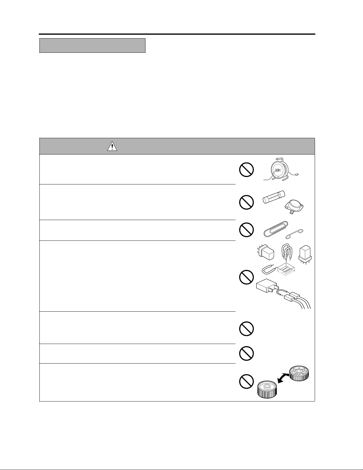
DANGER : PROHIBITED ACTIONS
• Using any cables or power cord not specified by Minolta.
• Using any fuse or thermostat not specified by Minolta. Safety will not be
assured, leading to a risk of fire and injury.
• Disabling fuse functions or bridging fuse terminals with wire, metal clips, sol-
der or similar object.
• Disabling relay functions (such as wedging paper between relay contacts)
• Disabling safety functions (interlocks, safety circuits, etc.) Safety will not be
assured, leading to a risk of fire and injury.
• Making any modification to the copier unless instructed by Minolta.
• Using parts not specified by Minolta.
S-2
SAFETY AND IMPORTANT WARNING ITEMS
2. CHECKPOINTS WHEN PERFORMING ON-SITE SERVICE
Minolta copiers are extensively tested before shipping, to ensure that all applicable safety standards are met, in
order to protect the customer and customer engineer (hereafter called the CE) from the risk of injury. However,
in daily use, any electrical equipment may be subject to parts wear and eventual failure. In order to maintain
safety and reliability, the CE must perform regular safety checks.
2.1 Power Supply
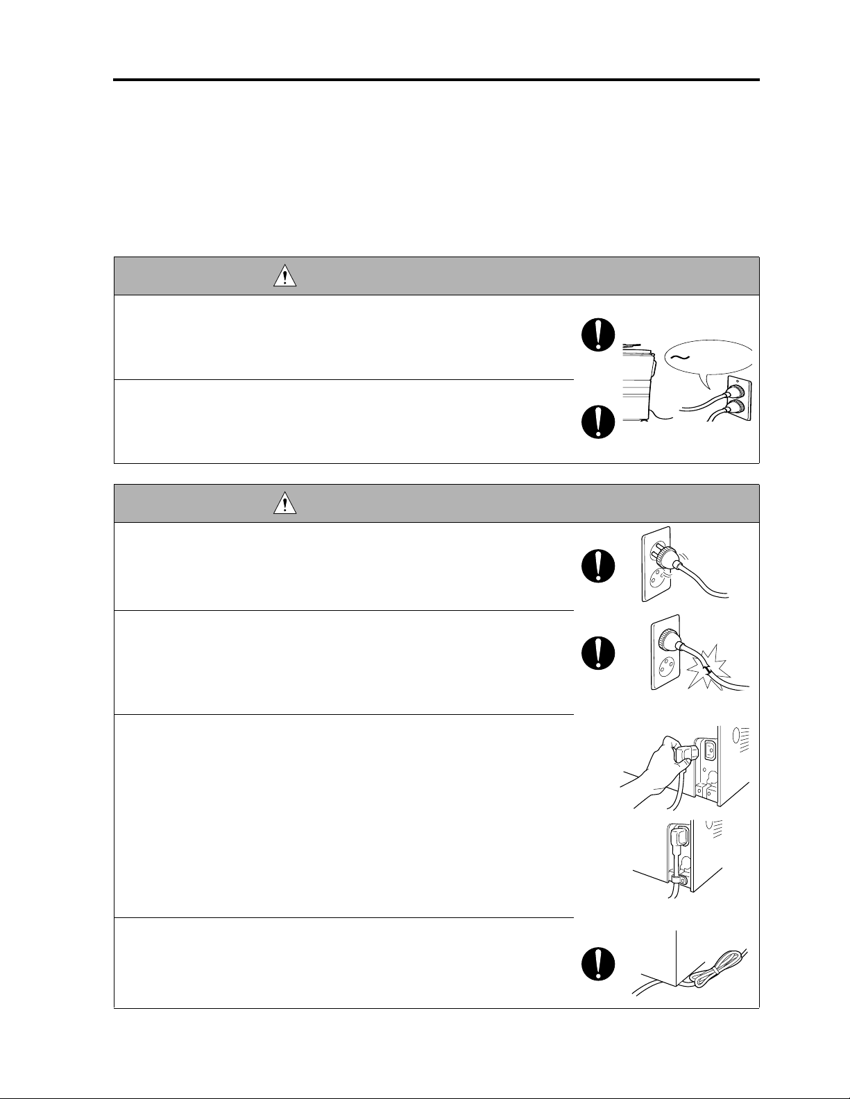
WARNING: Wall Outlet
• Check that main voltage is as specified. Plug the power cord into the dedi-
cated wall outlet with a capacity greater than the maximum power consump-
tion.
If excessive current flows in the wall outlet, fire may result.
• If two or more power cords can be plugged into the wall outlet, the total load
must not exceed the rating of the wall outlet.
If excessive current flows in the wall outlet, fire may result.
kw
WARNING: Power Plug and Cord
• Make sure the power cord is plugged in the wall outlet securely.
Contact problems may lead to increased resistance, overheating, and the
risk of fire.
• Check whether the power cord is damaged. Check whether the sheath is
damaged.
If the power plug, cord, or sheath is damaged, replace with a new power
cord (with plugs on both ends) specified by Minolta. Using the damaged
power cord may result in fire or electric shock.
• When using the power cord (inlet type) that came with this copier, be sure to
observe the following precautions:
a. Make sure the copier-side power plug is securely inserted in the socket
on the rear panel of the copier.
Secure the cord with a fixture properly.
b. If the power cord or sheath is damaged, replace with a new power cord
(with plugs on both ends) specified by Minolta.
If the power cord (inlet type) is not connected to the copier securely, a
contact problem may lead to increased resistance, overheating, and risk
of fire.
• Check whether the power cord is not stepped on or pinched by a table and
so on.
Overheating may occur there, leading to a risk of fire.
S-3

SAFETY AND IMPORTANT WARNING ITEMS
WARNING: Power Plug and Cord
• Do not bundle or tie the power cord.
Overheating may occur there, leading to a risk of fire.
• Check whether dust is collected around the power plug and wall outlet.
Using the power plug and wall outlet without removing dust may result in
fire.
• Do not insert the power plug into the wall outlet with a wet hand.
The risk of electric shock exists.
• When unplugging the power cord, grasp the plug, not the cable.
The cable may be broken, leading to a risk of fire and electric shock.
WARNING: Wiring
• Never use multi-plug adapters to plug multiple power cords in the same out-
let.
If used, the risk of fire exists.
• When an extension cord is required, use a specified one.
Current that can flow in the extension cord is limited, so using an
extension cord which is too long, may result in fire.
Do not use an extension cable reel with the cable taken up. Fire may
result.
WARNING: Ground Lead
• Check whether the copier is grounded properly.
If current leakage occurs in an ungrounded copier, you may suffer electric
shock while operating the copier. Connect the ground lead to one of the
following points:
a. Ground terminal of wall outlet
b. Ground terminal for which Class D work has been done
S-4

SAFETY AND IMPORTANT WARNING ITEMS
WARNING: Ground Lead
• Pay attention to the point to which the ground lead is connected.
Connecting the ground lead to an improper point such as the points listed
below results in a risk of explosion and electric shock:
a. Gas pipe (A risk of explosion or fire exists.)
b. Lightning rod (A risk of electric shock or fire exists.)
c. Telephone line ground (A risk of electric shock or fire exists in the case
of lightning.)
d. Water pipe or faucet (It may include a plastic portion.)
2.2. Installation Requirements
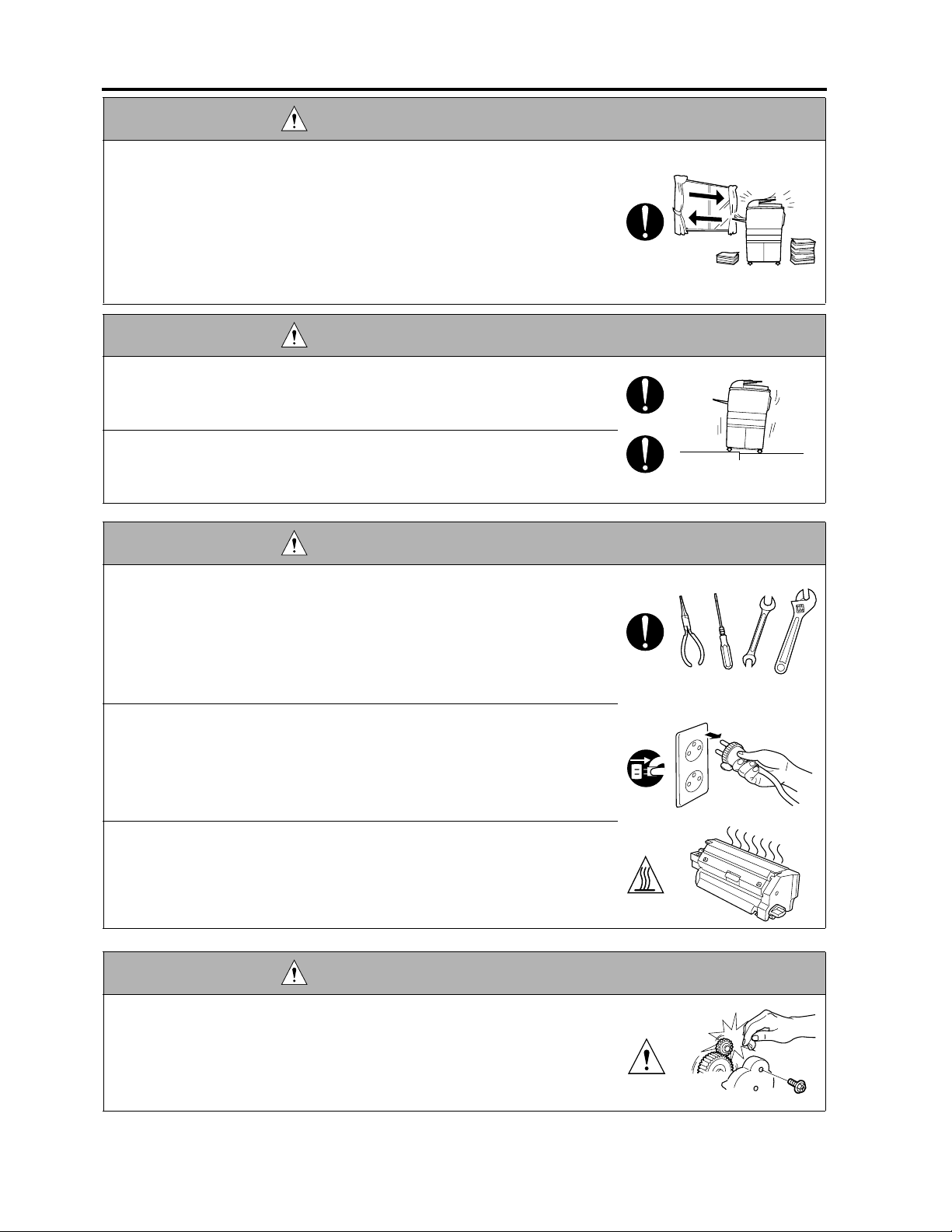
WARNING: Prohibited Installation Place
• Do not place the copier near flammable materials such as curtains or volatile
materials that may catch fire.
A risk of fire exists.
• Do not place the copier in a place exposed to water such as rain water.
A risk of fire and electric shock exists.
WARNING: Nonoperational Handling
• When the copier is not used over an extended period of time (holidays, etc.),
switch it off and unplug the power cord.
Dust collected around the power plug and outlet may cause fire.
CAUTION: Temperature and Humidity
• Do not place the copier in a place exposed to direct sunlight or near a heat
source such as a heater.
A risk of degradation in copier performance or deformation exists.
Do not place the copier in a place exposed to cool wind.
Recommended temperature and humidity are as follows:
Temperature: 10 °C to 30 °C
Humidity: 10 % to 80 % (no dew condensation)
Avoid other environments as much as possible.
CAUTION: Ventilation
• Do not place the copier in a place where there is much dust, cigarette smoke,
or ammonia gas.
Place the copier in a well ventilated place to prevent machine problems
and image faults.
S-5
SAFETY AND IMPORTANT WARNING ITEMS
CAUTION: Ventilation
• The copier generates ozone gas during operation, but it is not sufficient to be
harmful to the human body.
If a bad smell of ozone is present in the following cases, ventilate the room.
a. When the copier is used in a poorly ventilated room
b. When making a lot of copies
c. When using multiple copiers at the same time
CAUTION: Vibration
• When installing the copier, read the Installation Guide thoroughly. Be sure to
install the copier in a level and sturdy place.
Constant vibration will cause problems.
• Be sure to lock the caster stoppers.
In the case of an earthquake and so on, the copier may slide, leading to an
injury.
CAUTION: Inspection before Servicing
• Before conducting an inspection, read all relevant documentation (Service
manual, technical notices, etc.) and proceed with the inspection following the
prescribed procedure in safety clothes, using only the prescribed tools. Do
not make any adjustment not described in the documentation.
If the prescribed procedure or tool is not used, the copier may break and a
risk of injury or fire exists.
• Before conducting an inspection, be sure to disconnect the power plugs from
the copier and options.
When the power plug is inserted in the wall outlet, some units are still pow-
ered even if the POWER switch is turned OFF. A risk of electric shock
exists.
• The area around the fixing unit is hot.
You may get burnt.
DANGER: Work Performed with the Copier Powered
• Take every care when making adjustments or performing an operation check
with the copier powered.
If you make adjustments or perform an operation check with the external
cover detached, you may touch live or high-voltage parts or you may be
caught in moving gears or the timing belt, leading to a risk of injury.
S-6

SAFETY AND IMPORTANT WARNING ITEMS
DANGER: Work Performed with the Copier Powered
• Take every care when servicing with the external cover detached.
High-voltage exists around the drum unit. A risk of electric shock exists.
WARNING: Safety Checkpoints
• Check the exterior and frame for edges, burrs, and other damages.
The user or CE may be injured.
• Do not allow any metal parts such as clips, staples, and screws to fall into the
copier.
They can short internal circuits and cause electric shock or fire.
• Check wiring for squeezing and any other damage.
Current can leak, leading to a risk of electric shock or fire.
• When disconnecting connectors, grasp the connector, not the cable.
(Specifically, connectors of the AC line and high-voltage parts)
Current can leak, leading to a risk of electric shock or fire.
• Carefully remove all toner remnants and dust from electrical parts and elec-
trode units such as a charging corona unit.
Current can leak, leading to a risk of copier trouble or fire.
• Check high-voltage cables and sheaths for any damage.
Current can leak, leading to a risk of electric shock or fire.
• Check electrode units such as a charging corona unit for deterioration and
sign of leakage.
Current can leak, leading to a risk of trouble or fire.
• Before disassembling or adjusting the write unit incorporating a laser, make
sure that the power cord has been disconnected.
The laser light can enter your eye, leading to a risk of loss of eyesight.
• Do not remove the cover of the write unit. Do not supply power with the write
unit shifted from the specified mounting position.
The laser light can enter your eye, leading to a risk of loss of eyesight.
• When replacing a lithium battery, replace it with a new lithium battery speci-
fied in the Parts Guide Manual. Dispose of the used lithium battery using the
method specified by local authority.
Improper replacement can cause explosion.
S-7

SAFETY AND IMPORTANT WARNING ITEMS
WARNING: Safety Checkpoints
• After replacing a part to which AC voltage is applied (e.g., optical lamp and
fixing lamp), be sure to check the installation state.
A risk of fire exists.
• Check the interlock switch and actuator for loosening and check whether the
interlock functions properly.
If the interlock does not function, you may receive an electric shock or be
injured when you insert your hand in the copier (e.g., for clearing paper
jam).
• Make sure the wiring cannot come into contact with sharp edges, burrs, or
other pointed parts.
Current can leak, leading to a risk of electric shock or fire.
• Make sure that all screws, components, wiring, connectors, etc. that were
removed for safety check and maintenance have been reinstalled in the orig-
inal location. (Pay special attention to forgotten connectors, pinched cables,
forgotten screws, etc.)
A risk of copier trouble, electric shock, and fire exists.
DANGER: HANDLING OF SERVICE MATERIALS
• Toner and developer are not harmful substances, but care must be taken not
to breathe excessive amounts or let the substances come into contact with
eyes, etc. It may be stimulative.
If the substances get in the eye, rinse with plenty of water immediately.
When symptoms are noticeable, consult a physician.
• Never throw the used cartridge and toner into fire.
You may be burned due to dust explosion.
DANGER : HANDLING OF SERVICE MATERIALS
• Unplug the power cord from the wall outlet.
Drum cleaner (isopropyl alcohol) and roller cleaner (acetone-based) are
highly flammable and must be handled with care. A risk of fire exists.
S-8

SAFETY AND IMPORTANT WARNING ITEMS
DANGER : HANDLING OF SERVICE MATERIALS
• Do not replace the cover or turn the copier ON before any solvent remnants
on the cleaned parts have fully evaporated.
A risk of fire exists.
• Use only a small amount of cleaner at a time and take care not to spill any
liquid. If this happens, immediately wipe it off.
A risk of fire exists.
• When using any solvent, ventilate the room well.
Breathing large quantities of organic solvents can lead to discomfort.
3. MEASURES TO TAKE IN CASE OF AN ACCIDENT
• If an accident has occurred, the distributor who has been notified first must immediately take emergency
measures to provide relief to affected persons and to prevent further damage.
• If a report of a serious accident has been received from a customer, an on-site evaluation must be carried
out quickly and Minolta Corporation must be notified.
• To determine the cause of the accident, conditions and materials must be recorded through direct on-site
checks, in accordance with instructions issued by Minolta Corporation.
• For reports and measures concerning serious accidents, follow the regulations given in “Serious Accident
Report/Follow-up Procedures”.
4. CONCLUSION
• Safety of users and customer engineers depends highly on accurate maintenance and administration.
Therefore, safety can be maintained by the appropriate daily service work conducted by the customer
engineer.
• When performing service, each copier on the site must be tested for safety. The customer engineer must
verify the safety of parts and ensure appropriate management of the equipment.
S-9

SAFETY AND IMPORTANT WARNING ITEMS
SAFETY INFORMATION
IMPORTANT INFORMATION
The Center for Devices and Radiological Health (CDRH) of the U.S. Food and Drug Administration implemented
regulations for laser products manufactured since August 1, 1976. Compliance is mandatory for products mar-
keted in the United States.
This copier is certified as a “Class 1” laser product under the U.S.
Department of Health and Human Services (DHHS) Radiation Performance Standard according to the Radiation
Control for Health and Safety Act of 1968. Since radiation emitted inside this copier is completely confined within
protective housings and external covers, the laser beam cannot escape during any phase of normal user opera-
tion.
S-10

SAFETY AND IMPORTANT WARNING ITEMS
SAFETY CIRCUITS
This machine is provided with the following safety circuits to prevent machine faults from resulting in serious
accidents.
• Overall protection circuit
• Fixing upper lamp /1 (L2), Fixing upper lamp /2 (L3), Fixing lower lamp (L4) overheating prevention circuit
These safety circuits are described below to provide
the service engineer with a renewed awareness of
them in order to prevent servicing errors that may
impair their functions.
1. Overall protection circuit
CBR1
NF
CBR2
1.1 Protection by circuit breaker /1 (CBR1) and circuit breaker /2 (CBR2)
CBR1 and CBR2 interrupt the AC line instantaneously when an excessive current flows due to a short in
the AC line.
CAUTION:
The CBR1 and CBR2 functions must not be deactivated under any circumstances.
8050sf001
S-11

SAFETY AND IMPORTANT WARNING ITEMS
2. Fixing upper lamp /1 (L2), Fixing upper lamp /2 (L3), Fixing lower lamp (L4) overheating
prevention circuit
PRCB ACDB
TH1
TH3
TH2
TH4
Control
section
AC driver
section
RL1
RL1
FHCB
L2
TS1
L3
TS2
L4
8050sf002e
2.1 Protection by software
The output voltage from fixing temperature sensor /1 (TH1) and fixing temperature sensor /2 (TH2) is read
by the CPU. If this voltage is abnormal, L2, L3, and L4 are turned OFF by opening main relay (RL1).
CAUTION:
• The clearance between the fixing upper roller and TH1 and the clearance between the fixing
lower roller and TH2 must not be changed. When replacing them, make sure to comply with the
specified clearances.
• The RL1 function must not be deactivated under any circumstances.
2.2 Protection by the hardware circuit
The output voltages from fixing temperature sensor /1 (TH1), fixing temperature sensor /2 (TH2), fixing
temperature sensor /3 (TH3), and fixing temperature sensor /4 (TH4) are compared with the abnormality
judgment reference value in the comparator circuit. If the output voltage from TH1, TH2, TH3, or TH4
exceeds the reference value, L2, L3, and L4 are turned OFF by opening RL1.
CAUTION:
• The clearance between the fixing upper roller and TH1 and the clearance between the fixing
lower roller and TH2 must not be changed. When replacing them, make sure to comply with the
specified clearances.
• Periodically check the contact between the fixing upper roller and TH3 and the contact
between the fixing lower roller and TH4, and replace them if any abnormality is detected.
• The RL1 function must not be deactivated under any circumstances.
2.3 Protection by thermostat /1 (TS1) and thermostat /2 (TS2)
When the temperature of the fixing upper roller exceeds the specified value, TS1 is turned OFF, thus inter-
rupting the power to L2 and L3 directly. When the temperature of the fixing lower roller exceeds the speci-
fied value, TS2 is turned OFF, thus interrupting the power to L4 directly.
CAUTION:
Do not use any other electrical conductor in place of TS1 and TS2.
S-12
SAFETY AND IMPORTANT WARNING ITEMS
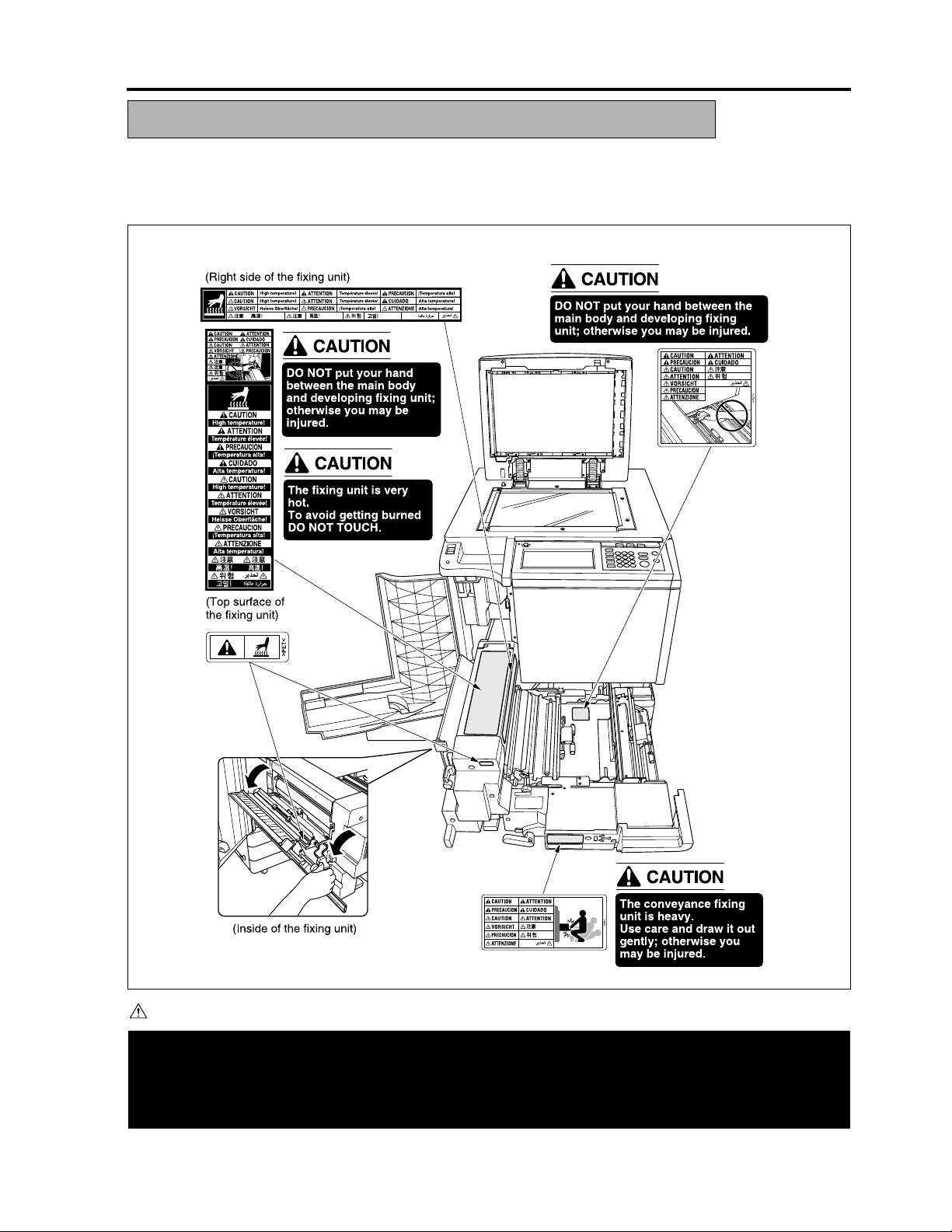
INDICATION OF WARNING ON THE MACHINE
Caution labels shown below are attached in some areas on/in the machine.
When accessing these areas for maintenance, repair, or adjustment, special care should be taken to avoid
burns and electric shock.
CAUTION
Please adhere to all caution labels to avoid burns or injury.
S-13
8050sf003e

SAFETY AND IMPORTANT WARNING ITEMS
CAUTION
-
Please adhere to all caution labels to avoid burns or injury.
S-14
8050sf004e

SAFETY AND IMPORTANT WARNING ITEMS
CAUTION
Please adhere to all caution labels to avoid burns or injury.
S-15
8050sf005e

SAFETY AND IMPORTANT WARNING ITEMS
CAUTION
-
Please adhere to all caution labels to avoid burns or injury.
S-16
8050sf006e

SAFETY AND IMPORTANT WARNING ITEMS
8050sf007e
CAUTION
Please adhere to all caution labels to avoid burns or injury.
S-17

SAFETY AND IMPORTANT WARNING ITEMS
Unplug the machine before removing platen glass.
Debrancher le copieur avant de retirer la vitre d'exposition.
Desenchufe la maquina antes de quitar el vidrio.
Desconecte a unidade da tomada antes de remover o vidro de exposicao.
PS
~
8050sf008e
CAUTION
-
Please adhere to all caution labels to avoid burns or injury.
S-18

CF5001 Ver.1.0 Sep. 2003 OUTLINE OF SYSTEM
I OUTLINE
1. OUTLINE OF SYSTEM
[8]
[7]
[11]
[11]
[10]
[9]
[12]
[12]
[13]
[1]
[6]
[14]
[2]
I OUTLINE
[3]
[4]
[5]
8050ma1001
[1] Main body [8] Trimmer (TMG-3)
[2] LCT (C-208) [9] Finisher (FN-9)
[3] Printer controller (Fiery S300 50C-K) [10] Finisher (FN-120)
[4] Hard disk (HDD-7) [11] Puncher (PK-5)
[5] Expansion memory (256MB x 4) [12] Cover sheet feeder (Cover Inserter D)
[6] Key counter [13] RADF (AFR-20)
[7] TMG-3 Connection kit (TMG Kit A) [14] Original cover Kit (OC-2)
1-1

PRODUCT SPECIFICATIONS CF5001 Ver.1.0 Sep. 2003
2. PRODUCT SPECIFICATIONS
A. Type
Type: Console type (floor-mounted type)
Copying method: Tandem intermediate transfer type electrostatic method
I OUTLINE
Original table: Fixed
Original alignment: Rear left side as reference
Photosensitive material: OPC
Sensitizing method: Laser writing
2
Paper feed trays: 3 trays method (500 sheets x 3, 80 to 90 g/m
Multisheet by-pass tray (250 sheets, 80 to 90 g/m
C-208 (2500 sheets, 80 to 90g/m
*1: Optional
2
) *1
) (400 sheets x 3, 105 g/m2)
2
) (200 sheets, 105g/m2)
B. Functions
Original to be copied: Sheet, book, solid object
Maximum original size: A3, or 11 x 17 (303 x 438 mm for non standard)
Copy size (for metric area): Tray 1 to 3: A3, B4, A4, A4R, B5, B5R, A5R,
8.5 x 11, 8.5 x 14, 11 x 17, 12 x 18, 13 x 19, wide paper *1
By-pass feed: A3, B4, A4, A4R, B5, B5R, A5R,
8.5 x 11, 8.5 x 11R, 11 x 17, 12 x 18, 13 x 19, wide paper *1
ADU: A3, B4, A4, A4R, B5, B5R, A5R,
8.5 x 11, 8.5 x 11R, 11 x 17, 12 x 18, 13 x 19, wide paper *1
Copy size (for inch area): Tray 1 to 3: A3, B4, A4, B5, B5R, 5.5 x 8.5R, 8.5 x 11, 8.5 x 11R,
8.5 x 14, 11 x 17, 12 x 18, 13 x 19, wide paper *1
By-pass feed: A3, B4, A4, B5, B5R, 5.5 x 8.5R, 8.5 x 11, 8.5 x 11R,
8.5 x 14, 11 x 17, 12 x 18, 13 x 19, wide paper *1
ADU: A3, B4, A4, B5, B5R, 5.5 x 8.5R, 8.5 x 11, 8.5 x 11R,
8.5 x 14, 11 x 17, 12 x 18, 13 x 19, wide paper *1
*1: Wide paper is available up to 330 x 487 mm.
Magnification: Fixed magnification
for metric area: x 1.000, x 2.000, x 1.414, x 1.224, x 1.154,
x 0.866, x 0.816, x 0.707, x 0.500
for inch area: x 1.000, x 2.000, x 1.545, x 1.294, x 1.214,
x 0.786, x 0.772, x 0.647, x 0.500
Special ratio magnification: 3 types
Zoom magnification:
x 0.250 to x 4.000 (graduated at increment of 0.1 %)
Vertical magnification:
x 0.250 to x 4.000 (graduated at increment of 0.1 %)
Horizontal magnification:
x 0.250 to x 4.000 (graduated at increment of 0.1 %)
Warm-up time (at room temperature of 20 °C with rated voltage)
for metric area: Less than 420 sec.
for inch area: Less than 390 sec.
1-2

CF5001 Ver.1.0 Sep. 2003 PRODUCT SPECIFICATIONS
First copy time: Full color: Less than 7.6 sec.
(platen mode, life size, manual density,
paper feed tray /1 to /3, plain paper, without gloss,
face up paper exit, A4 or 8.5 x 11)
Monochrome: Less than 7.6 sec. (platen mode, life size, manual density,
paper feed tray /1 to /3, plain paper, without gloss,
face up paper exit, A4 or 8.5 x 11)
Black-and-white: Less than 6.0 sec. (platen mode, life size, manual density,
paper feed tray /1 to /3, plain paper, without gloss,
face up paper exit, A4 or 8.5 x 11)
Continuous copy speed: Full color: 51 sheets/min. (A4, memory copy)
50 sheets/min. (8.5 x 11, memory copy)
Monochrome: 51 sheets/min. (A4, memory copy)
50 sheets/min. (8.5 x 11, memory copy)
Black-and-white: 51 sheets/min. (A4, memory copy)
50 sheets/min. (8.5 x 11, memory copy)
Continuous copy count: 9999 sheets, max. or 9999 copies
Paper exit tray loading capacity: 150 sheets (A4), max.
Copy density selection: AE, manual (9 steps)
Resolution: Scan: 600 dpi x 600 dpi
Copy: 600 dpi x 600 dpi
E-RDH memory *2 Standard: 128 MB for each color (Y, M, C, K);
Max.: 384 MB for each color (Y, M, C, K)
Interface: Serial port (USB Type B), Serial port (RS-232C), RJ45 Ethernet connector,
parallel port (based on IEEE 1284), Video interface for Fiery Controller.
No. of originals in memory: Full color: Priority in high resolution: 18 faces or more
Priority in smooth tone: 18 faces or more
Priority in high compression: 38 faces or more
Conditions
Original: KC #101/A3 (color)
Density: Manual 5
Mode: Character/picture, printed original, life size
Memory capacity: Standard 128 MB only loaded
Black-and-white/monochrome:
Priority in high resolution: 101 faces or more
Priority in smooth tone: 101 faces or more
Priority in high compression: 318 faces or more
Conditions:
Original: Image electronic institute FAX #4 chart/A4
Density: Manual 5
Mode: Character/picture, printed original, life size
Memory capacity: Standard 128 MB only loaded
Job: Job in the mode in which job memory is not used.
*2: Standard 128MB memory is packaged on the board. So, it cannot be changed for a new one.
Four slots are provided for expansion, and it is possible to install option memory.
(set of 4 by 256MB)
I OUTLINE
1-3

PRODUCT SPECIFICATIONS CF5001 Ver.1.0 Sep. 2003
C. Copy paper
2
2
2
2
2
I OUTLINE
*1 Label paper should be fed one at a time by the by-pass feed method.
Standard specified paper: For full color: Neusiedler Color Copy 90g/m
Hammermill Tidal 75 g/m
For black-and-white: Konica Business Class 80 g/m
Hammermill Laser Color Copy Photo White/
Brightness 96 105 g/m
Ordinary paper: High quality paper, coated paper and recycled paper of 64 g/m2 to 105 g/m
Special paper *1 Label paper, and ordinary paper of 106g/m2 to 256g/m
Coated paper of 106 g/m
feed it through C-208 (optional).
Double sided copy is unavailable for special paper that is other than the ordinary paper of 106 g/m
2
209 g/m
.
2
to 256 g/m2 is fed one at a time by by-pass feed. However, it is possible to
D. Machine data
Power source
for metric area: 230 VAC -14 % to 10.6 % 50 Hz
for inch area: 208 ~ 240 VAC ± 10% 60 Hz
Power consumption
for metric area: 3400 W max. (Full option)
for inch area: 3600 W max. (Full option)
Weight: Approx. 313 kg
Dimensions: 794 mm (W) x 889 mm (D) x 1056 mm (H) with platen cover provided
2
2
to
E. Maintenance and life
Maintenance: Once every 100,000 copies
Machine service life: 5,000,000 copies or 5 years (whichever earlier)
F. Consumables
Developer: Exclusively for CF5001
Toner: Exclusively for CF5001
Drum: Exclusively for CF5001 (φ60)
G. Operating environment
Temperature: 10°C to 30°C
Humidity: 10% RH to 80% RH
Note:
• The information herein may be subject to change for improvement without notice.
1-4

CF5001 Ver.1.0 Sep. 2003 CENTER CROSS SECTION
3. CENTER CROSS SECTION
[21]
[20]
[19]
[18]
[17]
[16]
[15]
[14]
[1][22]
[2]
I OUTLINE
[3]
[4]
[5]
[7]
[6]
[8]
[9]
[10]
[13]
[12]
[11]
[1] Process unit [12] Paper feed tray /3
[2] Developing unit /Y [13] Paper feed tray /2
[3] Developing unit /M [14] Paper feed tray /1
[4] Write unit /Y [15] ADU
[5] Write unit /M [16] Reverse section
[6] Write unit /C [17] Paper exit tray
[7] Developing unit /C [18] Paper exit section
[8] Developing unit /K [19] Transfer belt unit
[9] Write unit /K [20] Image correction unit
[10] By-pass tray [21] Scanner section
[11] Drum [22] CCD unit
8050ma1002
1-5

PAPER PATH CF5001 Ver.1.0 Sep. 2003
4. PAP ER PAT H
Front side
I OUTLINE
8050ma1029
1-6

CF5001 Ver.1.0 Sep. 2003 PAPER PATH
Back side
I OUTLINE
8050ma1030
1-7
 Loading...