

Page 1

Service Manual
[Field Service]
CF5001
Page 2

Dual references may be used on the following:
Official Options name : Popular Options name
AFR-20 : RADF, DF
C-208 : LT
FN-120 : FNS
FN-9 : FNS
Cover Inserter D : PI
PK-5 : PU
TMG-3 TU
In-System Writer : ISW
Page 3

CF5001 Field Service Ver.1.0 Sep 2003 CONTENTS
CONTENTS
SAFETY AND IMPORTANT WARNING ITEMS. . . . . . . . . . . . . . . . . . . . . . . . . . . . . . . . . . . . . . . . . . . . . S-1
IMPORTANT NOTICE . . . . . . . . . . . . . . . . . . . . . . . . . . . . . . . . . . . . . . . . . . . . . . . . . . . . . . . . . . . . . . . S-1
DESCRIPTION ITEMS FOR DANGER, WARNING AND CAUTION . . . . . . . . . . . . . . . . . . . . . . . . . . . . S-1
SAFETY WARNINGS . . . . . . . . . . . . . . . . . . . . . . . . . . . . . . . . . . . . . . . . . . . . . . . . . . . . . . . . . . . . . . . . S-2
SAFETY INFORMATION . . . . . . . . . . . . . . . . . . . . . . . . . . . . . . . . . . . . . . . . . . . . . . . . . . . . . . . . . . . . . S-10
IMPORTANT INFORMATION . . . . . . . . . . . . . . . . . . . . . . . . . . . . . . . . . . . . . . . . . . . . . . . . . . . . . . . . . S-10
SAFETY CIRCUITS . . . . . . . . . . . . . . . . . . . . . . . . . . . . . . . . . . . . . . . . . . . . . . . . . . . . . . . . . . . . . . . . S-11
INDICATION OF WARNING ON THE MACHINE . . . . . . . . . . . . . . . . . . . . . . . . . . . . . . . . . . . . . . . . . . S-13
I DISASSEMBLY/ASSEMBLY
1. EXTERIOR . . . . . . . . . . . . . . . . . . . . . . . . . . . . . . . . . . . . . . . . . . . . . . . . . . . . . . . . . . . . . . . . . . . . . . 1-1
1.1 Replacing the dust filter /2 . . . . . . . . . . . . . . . . . . . . . . . . . . . . . . . . . . . . . . . . . . . . . . . . . . . . . . . 1-1
1.2 Replacing the dust filter /1 and the ozone filter /1 . . . . . . . . . . . . . . . . . . . . . . . . . . . . . . . . . . . . . 1-2
1.3 Replacing the toner collection box. . . . . . . . . . . . . . . . . . . . . . . . . . . . . . . . . . . . . . . . . . . . . . . . . 1-4
1.4 Angle adjustment of the operation board. . . . . . . . . . . . . . . . . . . . . . . . . . . . . . . . . . . . . . . . . . . . 1-6
1.5 Removing and reinstalling the main board unit . . . . . . . . . . . . . . . . . . . . . . . . . . . . . . . . . . . . . . . 1-7
2. SCANNER . . . . . . . . . . . . . . . . . . . . . . . . . . . . . . . . . . . . . . . . . . . . . . . . . . . . . . . . . . . . . . . . . . . . . 1-11
2.1 Screws that must not be removed . . . . . . . . . . . . . . . . . . . . . . . . . . . . . . . . . . . . . . . . . . . . . . . . 1-11
2.2 Removing and reinstalling the platen glass. . . . . . . . . . . . . . . . . . . . . . . . . . . . . . . . . . . . . . . . . 1-11
2.3 Removing and reinstalling the CCD unit . . . . . . . . . . . . . . . . . . . . . . . . . . . . . . . . . . . . . . . . . . . 1-12
2.4 Removing and reinstalling the exposure unit. . . . . . . . . . . . . . . . . . . . . . . . . . . . . . . . . . . . . . . . 1-14
2.5 Removing and reinstalling the exposure lamp. . . . . . . . . . . . . . . . . . . . . . . . . . . . . . . . . . . . . . . 1-17
2.6 Removing the scanner wire . . . . . . . . . . . . . . . . . . . . . . . . . . . . . . . . . . . . . . . . . . . . . . . . . . . . . 1-18
2.7 Reinstalling the scanner wire. . . . . . . . . . . . . . . . . . . . . . . . . . . . . . . . . . . . . . . . . . . . . . . . . . . . 1-20
3. WRITING . . . . . . . . . . . . . . . . . . . . . . . . . . . . . . . . . . . . . . . . . . . . . . . . . . . . . . . . . . . . . . . . . . . . . . 1-23
3.1 Screw that must not be removed . . . . . . . . . . . . . . . . . . . . . . . . . . . . . . . . . . . . . . . . . . . . . . . . . 1-23
3.2 Removing and reinstalling the write unit . . . . . . . . . . . . . . . . . . . . . . . . . . . . . . . . . . . . . . . . . . . 1-24
4. PROCESS UNIT. . . . . . . . . . . . . . . . . . . . . . . . . . . . . . . . . . . . . . . . . . . . . . . . . . . . . . . . . . . . . . . . . 1-27
4.1 Flow of the disassembly of the process unit section . . . . . . . . . . . . . . . . . . . . . . . . . . . . . . . . . . 1-27
4.2 Cleaning the charging corona unit. . . . . . . . . . . . . . . . . . . . . . . . . . . . . . . . . . . . . . . . . . . . . . . . 1-28
4.3 Cleaning/replacing, removing and reinstalling the charging wire assy
/the charging control plate . . . . . . . . . . . . . . . . . . . . . . . . . . . . . . . . . . . . . . . . . . . . . . . . . . . . . . 1-30
4.4 Pulling out the process unit . . . . . . . . . . . . . . . . . . . . . . . . . . . . . . . . . . . . . . . . . . . . . . . . . . . . . 1-31
4.5 Removing and reinstalling the transfer belt unit . . . . . . . . . . . . . . . . . . . . . . . . . . . . . . . . . . . . . 1-32
4.6 Replacing the belt cleaning brush unit. . . . . . . . . . . . . . . . . . . . . . . . . . . . . . . . . . . . . . . . . . . . . 1-35
4.7 Replacing the belt cleaning blade . . . . . . . . . . . . . . . . . . . . . . . . . . . . . . . . . . . . . . . . . . . . . . . . 1-36
4.8 Replacing the toner collection sheet /1 . . . . . . . . . . . . . . . . . . . . . . . . . . . . . . . . . . . . . . . . . . . . 1-37
4.9 Replacing the belt separation claw . . . . . . . . . . . . . . . . . . . . . . . . . . . . . . . . . . . . . . . . . . . . . . . 1-38
4.10 Replacing the transfer belt. . . . . . . . . . . . . . . . . . . . . . . . . . . . . . . . . . . . . . . . . . . . . . . . . . . . . . 1-39
4.11 Replacing the 1st transfer roller. . . . . . . . . . . . . . . . . . . . . . . . . . . . . . . . . . . . . . . . . . . . . . . . . . 1-41
4.12 Replacing the 2nd transfer roller /U . . . . . . . . . . . . . . . . . . . . . . . . . . . . . . . . . . . . . . . . . . . . . . . 1-42
4.13 Replacing the drum cartridge . . . . . . . . . . . . . . . . . . . . . . . . . . . . . . . . . . . . . . . . . . . . . . . . . . . 1-43
I DIS./ASSEMBLYII ADJUSTMENTIII SERVICE TOOL
IV SERVICEV CODE LISTVI DIAGRAMS
i
Page 4

CONTENTS CF5001 Field Service Ver.1.0 Sep 2003
4.14 Removing and reinstalling the drum . . . . . . . . . . . . . . . . . . . . . . . . . . . . . . . . . . . . . . . . . . . . . . 1-44
4.15 Replacing the developing unit . . . . . . . . . . . . . . . . . . . . . . . . . . . . . . . . . . . . . . . . . . . . . . . . . . . 1-46
4.16 Replacing the developer . . . . . . . . . . . . . . . . . . . . . . . . . . . . . . . . . . . . . . . . . . . . . . . . . . . . . . . 1-48
4.17 Replacing the belt separation claw solenoid . . . . . . . . . . . . . . . . . . . . . . . . . . . . . . . . . . . . . . . . 1-50
4.18 Removing and reinstalling the process unit . . . . . . . . . . . . . . . . . . . . . . . . . . . . . . . . . . . . . . . . . 1-51
4.19 Removing and reinstalling the image correction unit . . . . . . . . . . . . . . . . . . . . . . . . . . . . . . . . . . 1-52
I DIS./ASSEMBLY
II ADJUSTMENT
III SERVICE TOOL
IV SERVICEV CODE LISTVI DIAGRAMS
5. TONER SUPPLY. . . . . . . . . . . . . . . . . . . . . . . . . . . . . . . . . . . . . . . . . . . . . . . . . . . . . . . . . . . . . . . . . 1-53
5.1 Opening and closing the toner supply section . . . . . . . . . . . . . . . . . . . . . . . . . . . . . . . . . . . . . . . 1-53
5.2 Replacing the charging dust filter. . . . . . . . . . . . . . . . . . . . . . . . . . . . . . . . . . . . . . . . . . . . . . . . . 1-54
6. PAPER FEED TRAYS /1 to /3 . . . . . . . . . . . . . . . . . . . . . . . . . . . . . . . . . . . . . . . . . . . . . . . . . . . . . . . 1-55
6.1 Removing and reinstalling the paper feed unit. . . . . . . . . . . . . . . . . . . . . . . . . . . . . . . . . . . . . . . 1-55
6.2 Removing and reinstalling the paper feed trays /1 to /3. . . . . . . . . . . . . . . . . . . . . . . . . . . . . . . . 1-57
6.3 Replacing the paper feed roller and the feed rubber . . . . . . . . . . . . . . . . . . . . . . . . . . . . . . . . . . 1-58
6.4 Replacing the double feed prevention rubber . . . . . . . . . . . . . . . . . . . . . . . . . . . . . . . . . . . . . . . 1-60
6.5 Replacing the paper feed clutch and the pre-registration clutch . . . . . . . . . . . . . . . . . . . . . . . . . 1-61
6.6 Removing and reinstalling the tray up/down wire . . . . . . . . . . . . . . . . . . . . . . . . . . . . . . . . . . . . 1-62
7. BY-PASS TRAY. . . . . . . . . . . . . . . . . . . . . . . . . . . . . . . . . . . . . . . . . . . . . . . . . . . . . . . . . . . . . . . . . . 1-66
7.1 Replacing the paper feed roller and the feed roller . . . . . . . . . . . . . . . . . . . . . . . . . . . . . . . . . . . 1-66
7.2 Replacing the double feed prevention roller . . . . . . . . . . . . . . . . . . . . . . . . . . . . . . . . . . . . . . . . 1-68
7.3 Replacing the paper feed clutch /BP . . . . . . . . . . . . . . . . . . . . . . . . . . . . . . . . . . . . . . . . . . . . . . 1-69
8. VERTICAL CONVEYANCE. . . . . . . . . . . . . . . . . . . . . . . . . . . . . . . . . . . . . . . . . . . . . . . . . . . . . . . . . 1-71
8.1 Removing and reinstalling the vertical conveyance. . . . . . . . . . . . . . . . . . . . . . . . . . . . . . . . . . . 1-71
8.2 Replacing the intermediate conveyance clutch /1 . . . . . . . . . . . . . . . . . . . . . . . . . . . . . . . . . . . . 1-74
9. FIXING . . . . . . . . . . . . . . . . . . . . . . . . . . . . . . . . . . . . . . . . . . . . . . . . . . . . . . . . . . . . . . . . . . . . . . . . 1-75
9.1 Screws that must not be removed . . . . . . . . . . . . . . . . . . . . . . . . . . . . . . . . . . . . . . . . . . . . . . . . 1-75
9.2 Removing and reinstalling the fixing unit . . . . . . . . . . . . . . . . . . . . . . . . . . . . . . . . . . . . . . . . . . . 1-76
9.3 Replacing the fixing upper heater lamps /1 and /2. . . . . . . . . . . . . . . . . . . . . . . . . . . . . . . . . . . . 1-77
9.4 Replacing the fixing lower heater lamp . . . . . . . . . . . . . . . . . . . . . . . . . . . . . . . . . . . . . . . . . . . . 1-79
9.5 Replacing the fixing roller /U, ball bearing /U and the heat insulating sleeve /U . . . . . . . . . . . . . 1-82
9.6 Replacing the fixing roller /L, ball bearing /L and the heat insulating sleeve /L . . . . . . . . . . . . . . 1-84
9.7 Replacing the fixing temperature sensor /3, and removing and reinstalling
the fixing temperature sensor /1 and the thermostat /1 . . . . . . . . . . . . . . . . . . . . . . . . . . . . . . . . 1-86
9.8 Replacing the fixing temperature sensor /4, and removing and reinstalling
the fixing temperature sensor /2 and the thermostat /L . . . . . . . . . . . . . . . . . . . . . . . . . . . . . . . . 1-91
9.9 Replacing the fixing drive gear. . . . . . . . . . . . . . . . . . . . . . . . . . . . . . . . . . . . . . . . . . . . . . . . . . . 1-96
9.10 Replacing the fixing cleaning unit . . . . . . . . . . . . . . . . . . . . . . . . . . . . . . . . . . . . . . . . . . . . . . . . 1-98
9.11 Replacing the fixing torque limiter . . . . . . . . . . . . . . . . . . . . . . . . . . . . . . . . . . . . . . . . . . . . . . . 1-100
10. REGISTRATION/ADU/REVERSE/PAPER EXIT . . . . . . . . . . . . . . . . . . . . . . . . . . . . . . . . . . . . . . . . 1-102
10.1 Removing and reinstalling the ADU. . . . . . . . . . . . . . . . . . . . . . . . . . . . . . . . . . . . . . . . . . . . . . 1-102
10.2 Replacing the registration cleaning sheet . . . . . . . . . . . . . . . . . . . . . . . . . . . . . . . . . . . . . . . . . 1-104
10.3 Replacing the separation discharging plate unit . . . . . . . . . . . . . . . . . . . . . . . . . . . . . . . . . . . . 1-105
10.4 Replacing the transfer ground plate unit and the 2nd transfer roller /L . . . . . . . . . . . . . . . . . . . 1-106
10.5 Replacing the registration roller . . . . . . . . . . . . . . . . . . . . . . . . . . . . . . . . . . . . . . . . . . . . . . . . . 1-107
10.6 Replacing the intermediate conveyance clutches /2 and /3. . . . . . . . . . . . . . . . . . . . . . . . . . . . 1-109
10.7 Replacing the ADU conveyance clutches /1 and /2. . . . . . . . . . . . . . . . . . . . . . . . . . . . . . . . . . 1-110
10.8 Replacing the ADU pre-registration clutch. . . . . . . . . . . . . . . . . . . . . . . . . . . . . . . . . . . . . . . . . 1-111
10.9 Replacing the decurler roller . . . . . . . . . . . . . . . . . . . . . . . . . . . . . . . . . . . . . . . . . . . . . . . . . . . 1-112
ii
Page 5

CF5001 Field Service Ver.1.0 Sep 2003 CONTENTS
11. OTHER . . . . . . . . . . . . . . . . . . . . . . . . . . . . . . . . . . . . . . . . . . . . . . . . . . . . . . . . . . . . . . . . . . . . . . . 1-114
11.1 Installation of the Key Counter Socket (OPTION) . . . . . . . . . . . . . . . . . . . . . . . . . . . . . . . . . . . 1-114
11.2 Installation / Remove of the Memory Unit (OPTION). . . . . . . . . . . . . . . . . . . . . . . . . . . . . . . . . 1-115
AFR-20 DISASSEMBLY/ASSEMBLY
1. EXTERIOR . . . . . . . . . . . . . . . . . . . . . . . . . . . . . . . . . . . . . . . . . . . . . . . . . . . . . . . . . . . . . . . . . . . . 1-117
1.1 RADF hinge opening/closing angle adjustment. . . . . . . . . . . . . . . . . . . . . . . . . . . . . . . . . . . . . 1-117
1.2 Removing and reinstalling the front cover . . . . . . . . . . . . . . . . . . . . . . . . . . . . . . . . . . . . . . . . . 1-119
1.3 Removing and reinstalling the rear cover . . . . . . . . . . . . . . . . . . . . . . . . . . . . . . . . . . . . . . . . . 1-120
1.4 Removing and reinstalling the registration roller cover . . . . . . . . . . . . . . . . . . . . . . . . . . . . . . . 1-121
2. PAPER FEED . . . . . . . . . . . . . . . . . . . . . . . . . . . . . . . . . . . . . . . . . . . . . . . . . . . . . . . . . . . . . . . . . . 1-122
2.1 Cleaning the no paper sensor . . . . . . . . . . . . . . . . . . . . . . . . . . . . . . . . . . . . . . . . . . . . . . . . . . 1-122
2.2 Removing and reinstalling the paper feed unit . . . . . . . . . . . . . . . . . . . . . . . . . . . . . . . . . . . . . 1-123
2.3 Replacing the paper feed roller and the feed roller . . . . . . . . . . . . . . . . . . . . . . . . . . . . . . . . . . 1-125
2.4 Replacing the double feed prevention roller . . . . . . . . . . . . . . . . . . . . . . . . . . . . . . . . . . . . . . . 1-127
3. PAPER FEED . . . . . . . . . . . . . . . . . . . . . . . . . . . . . . . . . . . . . . . . . . . . . . . . . . . . . . . . . . . . . . . . . . 1-129
3.1 Cleaning the registration roller. . . . . . . . . . . . . . . . . . . . . . . . . . . . . . . . . . . . . . . . . . . . . . . . . . 1-129
3.2 Cleaning the registration sensor . . . . . . . . . . . . . . . . . . . . . . . . . . . . . . . . . . . . . . . . . . . . . . . . 1-130
3.3 Removing and reinstalling the conveyance belt . . . . . . . . . . . . . . . . . . . . . . . . . . . . . . . . . . . . 1-131
4. REVERSE/PAPER EXIT . . . . . . . . . . . . . . . . . . . . . . . . . . . . . . . . . . . . . . . . . . . . . . . . . . . . . . . . . . 1-133
4.1 Cleaning the paper exit roller/the paper exit sensor . . . . . . . . . . . . . . . . . . . . . . . . . . . . . . . . . 1-133
4.2 Cleaning the reverse roller . . . . . . . . . . . . . . . . . . . . . . . . . . . . . . . . . . . . . . . . . . . . . . . . . . . . 1-133
5. REMOVING AND REINSTALLING RADF . . . . . . . . . . . . . . . . . . . . . . . . . . . . . . . . . . . . . . . . . . . . 1-134
C-208 DISASSEMBLY/ASSEMBLY
1. EXTERIOR . . . . . . . . . . . . . . . . . . . . . . . . . . . . . . . . . . . . . . . . . . . . . . . . . . . . . . . . . . . . . . . . . . . . 1-135
1.1 Removing and reinstalling the front cover . . . . . . . . . . . . . . . . . . . . . . . . . . . . . . . . . . . . . . . . . 1-135
1.2 Removing and reinstalling the clutch replacement cover and the rear cover . . . . . . . . . . . . . . 1-137
1.3 Removing and reinstalling the paper feed pick-up cover. . . . . . . . . . . . . . . . . . . . . . . . . . . . . . 1-138
2. PAPER FEED . . . . . . . . . . . . . . . . . . . . . . . . . . . . . . . . . . . . . . . . . . . . . . . . . . . . . . . . . . . . . . . . . . 1-139
2.1 Cleaning the paper dust removing brush. . . . . . . . . . . . . . . . . . . . . . . . . . . . . . . . . . . . . . . . . . 1-139
2.2 Removing and reinstalling the paper feed unit . . . . . . . . . . . . . . . . . . . . . . . . . . . . . . . . . . . . . 1-140
2.3 Replacing the paper feed roller and the feed roller . . . . . . . . . . . . . . . . . . . . . . . . . . . . . . . . . . 1-141
2.4 Replacing the double feed prevention roller . . . . . . . . . . . . . . . . . . . . . . . . . . . . . . . . . . . . . . . 1-142
2.5 Replacing the paper feed clutch and the pre-registration clutch . . . . . . . . . . . . . . . . . . . . . . . . 1-144
3. TRAY UP/DOWN . . . . . . . . . . . . . . . . . . . . . . . . . . . . . . . . . . . . . . . . . . . . . . . . . . . . . . . . . . . . . . . 1-145
3.1 Removing and reinstalling the rear drive. . . . . . . . . . . . . . . . . . . . . . . . . . . . . . . . . . . . . . . . . . 1-145
3.2 Removing and reinstalling the up/down wire . . . . . . . . . . . . . . . . . . . . . . . . . . . . . . . . . . . . . . . 1-150
I DIS./ASSEMBLYII ADJUSTMENTIII SERVICE TOOL
IV SERVICEV CODE LISTVI DIAGRAMS
FN-9/FN120 DISASSEMBLY/ASSEMBLY
1. EXTERIOR . . . . . . . . . . . . . . . . . . . . . . . . . . . . . . . . . . . . . . . . . . . . . . . . . . . . . . . . . . . . . . . . . . . . 1-159
1.1 Removing and reinstalling of the booklet tray (FN-9 only). . . . . . . . . . . . . . . . . . . . . . . . . . . . . 1-159
1.2 Removing and reinstalling of the top cover /1 . . . . . . . . . . . . . . . . . . . . . . . . . . . . . . . . . . . . . . 1-160
1.3 Removing and reinstalling of the top cover /2 . . . . . . . . . . . . . . . . . . . . . . . . . . . . . . . . . . . . . . 1-160
1.4 Removing and reinstalling of the side cover . . . . . . . . . . . . . . . . . . . . . . . . . . . . . . . . . . . . . . . 1-161
1.5 Removing and reinstalling of the finisher door . . . . . . . . . . . . . . . . . . . . . . . . . . . . . . . . . . . . . 1-161
iii
Page 6

CONTENTS CF5001 Field Service Ver.1.0 Sep 2003
1.6 Removing and reinstalling of the rear cover . . . . . . . . . . . . . . . . . . . . . . . . . . . . . . . . . . . . . . . 1-162
1.7 Removing and reinstalling of the main tray . . . . . . . . . . . . . . . . . . . . . . . . . . . . . . . . . . . . . . . . 1-163
1.8 Removing and reinstalling of the main paper exit opening cover . . . . . . . . . . . . . . . . . . . . . . . 1-164
1.9 Removing and reinstalling of the booklet paper exit opening cover (FN-9 only) . . . . . . . . . . . . 1-164
2. CONVEYANCE . . . . . . . . . . . . . . . . . . . . . . . . . . . . . . . . . . . . . . . . . . . . . . . . . . . . . . . . . . . . . . . . . 1-165
2.1 Replacing the paper exit roller /A (sponge roller). . . . . . . . . . . . . . . . . . . . . . . . . . . . . . . . . . . . 1-165
I DIS./ASSEMBLY
II ADJUSTMENT
2.2 Replacing the intermediate conveyance roller (sponge roller). . . . . . . . . . . . . . . . . . . . . . . . . . 1-167
2.3 Removing and reinstalling of the paper exit opening unit . . . . . . . . . . . . . . . . . . . . . . . . . . . . . 1-168
3. MAIN TRAY. . . . . . . . . . . . . . . . . . . . . . . . . . . . . . . . . . . . . . . . . . . . . . . . . . . . . . . . . . . . . . . . . . . . 1-170
3.1 Replacing the tray up/down motor . . . . . . . . . . . . . . . . . . . . . . . . . . . . . . . . . . . . . . . . . . . . . . . 1-170
3.2 Removing and reinstalling of the up/down wire . . . . . . . . . . . . . . . . . . . . . . . . . . . . . . . . . . . . . 1-171
4. STACKER . . . . . . . . . . . . . . . . . . . . . . . . . . . . . . . . . . . . . . . . . . . . . . . . . . . . . . . . . . . . . . . . . . . . . 1-175
4.1 Replacing the stacking assist roller . . . . . . . . . . . . . . . . . . . . . . . . . . . . . . . . . . . . . . . . . . . . . . 1-175
4.2 Removing and reinstalling of the stacker unit cover . . . . . . . . . . . . . . . . . . . . . . . . . . . . . . . . . 1-175
4.3 Removing and reinstalling of the stacker unit . . . . . . . . . . . . . . . . . . . . . . . . . . . . . . . . . . . . . . 1-176
5. STAPLER . . . . . . . . . . . . . . . . . . . . . . . . . . . . . . . . . . . . . . . . . . . . . . . . . . . . . . . . . . . . . . . . . . . . . 1-179
5.1 Removing and reinstalling of the stapler unit cover . . . . . . . . . . . . . . . . . . . . . . . . . . . . . . . . . . 1-179
5.2 Replacing the clincher . . . . . . . . . . . . . . . . . . . . . . . . . . . . . . . . . . . . . . . . . . . . . . . . . . . . . . . . 1-180
5.3 Replacing the stapler . . . . . . . . . . . . . . . . . . . . . . . . . . . . . . . . . . . . . . . . . . . . . . . . . . . . . . . . . 1-182
PK-5 DISASSEMBLY/ASSEMBLY
1. PUNCH SECTION . . . . . . . . . . . . . . . . . . . . . . . . . . . . . . . . . . . . . . . . . . . . . . . . . . . . . . . . . . . . . . 1-185
III SERVICE TOOL
1.1 Replacing the Punch unit . . . . . . . . . . . . . . . . . . . . . . . . . . . . . . . . . . . . . . . . . . . . . . . . . . . . . . 1-185
1.2 Cleaning the Punch Edges and Punch Scraps Full PS (PS802) . . . . . . . . . . . . . . . . . . . . . . . . 1-188
Cover Inserter D DISASSEMBLY/ASSEMBLY
1. External Section . . . . . . . . . . . . . . . . . . . . . . . . . . . . . . . . . . . . . . . . . . . . . . . . . . . . . . . . . . . . . . . . 1-189
1.1 Removing / Re-installing the External covers . . . . . . . . . . . . . . . . . . . . . . . . . . . . . . . . . . . . . . 1-189
2. Paper feed unit . . . . . . . . . . . . . . . . . . . . . . . . . . . . . . . . . . . . . . . . . . . . . . . . . . . . . . . . . . . . . . . . . 1-191
IV SERVICEV CODE LISTVI DIAGRAMS
2.1 Replacing the Paper feed roller and Feed roller . . . . . . . . . . . . . . . . . . . . . . . . . . . . . . . . . . . . 1-191
2.2 Replacing the Double feed prevent roller and Torque limiter . . . . . . . . . . . . . . . . . . . . . . . . . . . 1-192
TMG-3 DISASSEMBLY/ASSEMBLY
1. TRIMMER . . . . . . . . . . . . . . . . . . . . . . . . . . . . . . . . . . . . . . . . . . . . . . . . . . . . . . . . . . . . . . . . . . . . . 1-193
1.1 Replacing the trimmer knife /U and trimmer knife /L . . . . . . . . . . . . . . . . . . . . . . . . . . . . . . . . . 1-193
II ADJUSTMENT
1. HOW TO USE THE ADJUSTMENT SECTION. . . . . . . . . . . . . . . . . . . . . . . . . . . . . . . . . . . . . . . . . . . 2-1
1.1 Composition . . . . . . . . . . . . . . . . . . . . . . . . . . . . . . . . . . . . . . . . . . . . . . . . . . . . . . . . . . . . . . . . . . 2-1
2. ADJUSTMENTS WHEN REPLACING PARTS . . . . . . . . . . . . . . . . . . . . . . . . . . . . . . . . . . . . . . . . . . . 2-1
3. LIST OF ADJUSTMENT ITEMS . . . . . . . . . . . . . . . . . . . . . . . . . . . . . . . . . . . . . . . . . . . . . . . . . . . . . . 2-2
4. MODE CHANGE MENU . . . . . . . . . . . . . . . . . . . . . . . . . . . . . . . . . . . . . . . . . . . . . . . . . . . . . . . . . . . . 2-4
4.1 Setting method. . . . . . . . . . . . . . . . . . . . . . . . . . . . . . . . . . . . . . . . . . . . . . . . . . . . . . . . . . . . . . . . 2-4
4.2 Display transition of 36 modes . . . . . . . . . . . . . . . . . . . . . . . . . . . . . . . . . . . . . . . . . . . . . . . . . . . . 2-5
4.3 Display transition of 25 modes . . . . . . . . . . . . . . . . . . . . . . . . . . . . . . . . . . . . . . . . . . . . . . . . . . . . 2-7
4.4 Display transition of Key Operation modes . . . . . . . . . . . . . . . . . . . . . . . . . . . . . . . . . . . . . . . . . . 2-8
iv
Page 7

CF5001 Field Service Ver.1.0 Sep 2003 CONTENTS
5. CHECKING BY THE P FUNCTION . . . . . . . . . . . . . . . . . . . . . . . . . . . . . . . . . . . . . . . . . . . . . . . . . . 2-10
5.1 Checking method of the P function . . . . . . . . . . . . . . . . . . . . . . . . . . . . . . . . . . . . . . . . . . . . . . . 2-10
6. 25 MODE . . . . . . . . . . . . . . . . . . . . . . . . . . . . . . . . . . . . . . . . . . . . . . . . . . . . . . . . . . . . . . . . . . . . . . 2-11
6.1 List of adjustment items for 25 mode. . . . . . . . . . . . . . . . . . . . . . . . . . . . . . . . . . . . . . . . . . . . . . 2-11
6.2 Setting method . . . . . . . . . . . . . . . . . . . . . . . . . . . . . . . . . . . . . . . . . . . . . . . . . . . . . . . . . . . . . . 2-12
6.3 Setting software DIPSW . . . . . . . . . . . . . . . . . . . . . . . . . . . . . . . . . . . . . . . . . . . . . . . . . . . . . . . 2-12
6.4 Paper size setting . . . . . . . . . . . . . . . . . . . . . . . . . . . . . . . . . . . . . . . . . . . . . . . . . . . . . . . . . . . . 2-25
6.4.1 Standard size setting . . . . . . . . . . . . . . . . . . . . . . . . . . . . . . . . . . . . . . . . . . . . . . . . . . . . . 2-25
6.4.2 Non-standard size setting . . . . . . . . . . . . . . . . . . . . . . . . . . . . . . . . . . . . . . . . . . . . . . . . . 2-25
6.4.3 Wide paper setting . . . . . . . . . . . . . . . . . . . . . . . . . . . . . . . . . . . . . . . . . . . . . . . . . . . . . . . 2-25
6.5 PM count setting . . . . . . . . . . . . . . . . . . . . . . . . . . . . . . . . . . . . . . . . . . . . . . . . . . . . . . . . . . . . . 2-26
6.5.1 Count reset. . . . . . . . . . . . . . . . . . . . . . . . . . . . . . . . . . . . . . . . . . . . . . . . . . . . . . . . . . . . . 2-26
6.5.2 Change setting. . . . . . . . . . . . . . . . . . . . . . . . . . . . . . . . . . . . . . . . . . . . . . . . . . . . . . . . . . 2-26
6.6 Data collection . . . . . . . . . . . . . . . . . . . . . . . . . . . . . . . . . . . . . . . . . . . . . . . . . . . . . . . . . . . . . . . 2-27
6.7 Parts counter . . . . . . . . . . . . . . . . . . . . . . . . . . . . . . . . . . . . . . . . . . . . . . . . . . . . . . . . . . . . . . . . 2-42
6.7.1 Count of special parts . . . . . . . . . . . . . . . . . . . . . . . . . . . . . . . . . . . . . . . . . . . . . . . . . . . . 2-42
6.7.2 Count of each parts . . . . . . . . . . . . . . . . . . . . . . . . . . . . . . . . . . . . . . . . . . . . . . . . . . . . . . 2-47
6.8 Password setting . . . . . . . . . . . . . . . . . . . . . . . . . . . . . . . . . . . . . . . . . . . . . . . . . . . . . . . . . . . . . 2-48
6.9 Telephone number setting . . . . . . . . . . . . . . . . . . . . . . . . . . . . . . . . . . . . . . . . . . . . . . . . . . . . . . 2-48
6.10 M/C serial number setting . . . . . . . . . . . . . . . . . . . . . . . . . . . . . . . . . . . . . . . . . . . . . . . . . . . . . . 2-49
6.11 Indication of ROM version . . . . . . . . . . . . . . . . . . . . . . . . . . . . . . . . . . . . . . . . . . . . . . . . . . . . . . 2-49
6.12 ISW . . . . . . . . . . . . . . . . . . . . . . . . . . . . . . . . . . . . . . . . . . . . . . . . . . . . . . . . . . . . . . . . . . . . . . . 2-49
6.13 Setting date input. . . . . . . . . . . . . . . . . . . . . . . . . . . . . . . . . . . . . . . . . . . . . . . . . . . . . . . . . . . . . 2-50
6.14 Board change mode . . . . . . . . . . . . . . . . . . . . . . . . . . . . . . . . . . . . . . . . . . . . . . . . . . . . . . . . . . 2-50
7. 36 MODE . . . . . . . . . . . . . . . . . . . . . . . . . . . . . . . . . . . . . . . . . . . . . . . . . . . . . . . . . . . . . . . . . . . . . . 2-51
7.1 Setting method . . . . . . . . . . . . . . . . . . . . . . . . . . . . . . . . . . . . . . . . . . . . . . . . . . . . . . . . . . . . . . 2-51
7.2 Process adjustment . . . . . . . . . . . . . . . . . . . . . . . . . . . . . . . . . . . . . . . . . . . . . . . . . . . . . . . . . . . 2-51
7.2.1 High voltage adjustment. . . . . . . . . . . . . . . . . . . . . . . . . . . . . . . . . . . . . . . . . . . . . . . . . . . 2-52
7.2.2 Drum peculiarity adjustment. . . . . . . . . . . . . . . . . . . . . . . . . . . . . . . . . . . . . . . . . . . . . . . . 2-52
7.2.3 Sensor output check . . . . . . . . . . . . . . . . . . . . . . . . . . . . . . . . . . . . . . . . . . . . . . . . . . . . . 2-58
7.2.4 Exclusive paper setting . . . . . . . . . . . . . . . . . . . . . . . . . . . . . . . . . . . . . . . . . . . . . . . . . . . 2-58
7.2.5 Recall standard data . . . . . . . . . . . . . . . . . . . . . . . . . . . . . . . . . . . . . . . . . . . . . . . . . . . . . 2-59
7.3 Image adjustment . . . . . . . . . . . . . . . . . . . . . . . . . . . . . . . . . . . . . . . . . . . . . . . . . . . . . . . . . . . . 2-60
7.3.1 Magnification adjustment . . . . . . . . . . . . . . . . . . . . . . . . . . . . . . . . . . . . . . . . . . . . . . . . . . 2-60
7.3.2 Timing adjustment . . . . . . . . . . . . . . . . . . . . . . . . . . . . . . . . . . . . . . . . . . . . . . . . . . . . . . . 2-66
7.3.3 RADF adjustment . . . . . . . . . . . . . . . . . . . . . . . . . . . . . . . . . . . . . . . . . . . . . . . . . . . . . . . . 2-74
7.3.4 Centring adjustment . . . . . . . . . . . . . . . . . . . . . . . . . . . . . . . . . . . . . . . . . . . . . . . . . . . . . . 2-76
7.3.5 Non-image area erase check . . . . . . . . . . . . . . . . . . . . . . . . . . . . . . . . . . . . . . . . . . . . . . . 2-79
7.3.6 Recall standard data . . . . . . . . . . . . . . . . . . . . . . . . . . . . . . . . . . . . . . . . . . . . . . . . . . . . . 2-80
7.4 Image quality adjustment. . . . . . . . . . . . . . . . . . . . . . . . . . . . . . . . . . . . . . . . . . . . . . . . . . . . . . . 2-81
7.4.1 Scanner gamma adjustment . . . . . . . . . . . . . . . . . . . . . . . . . . . . . . . . . . . . . . . . . . . . . . . 2-81
7.4.2 Printer gamma adjustment . . . . . . . . . . . . . . . . . . . . . . . . . . . . . . . . . . . . . . . . . . . . . . . . . 2-82
7.4.3 Sharpness adjustment . . . . . . . . . . . . . . . . . . . . . . . . . . . . . . . . . . . . . . . . . . . . . . . . . . . . 2-87
7.4.4 Contrast adjustment . . . . . . . . . . . . . . . . . . . . . . . . . . . . . . . . . . . . . . . . . . . . . . . . . . . . . . 2-88
7.4.5 Image judge adjustment . . . . . . . . . . . . . . . . . . . . . . . . . . . . . . . . . . . . . . . . . . . . . . . . . . . 2-88
7.4.6 ACS adjustment . . . . . . . . . . . . . . . . . . . . . . . . . . . . . . . . . . . . . . . . . . . . . . . . . . . . . . . . . 2-90
7.4.7 Density adjustment. . . . . . . . . . . . . . . . . . . . . . . . . . . . . . . . . . . . . . . . . . . . . . . . . . . . . . . 2-91
I DIS./ASSEMBLYII ADJUSTMENTIII SERVICE TOOL
IV SERVICEV CODE LISTVI DIAGRAMS
v
Page 8

CONTENTS CF5001 Field Service Ver.1.0 Sep 2003
7.4.8 Tone adjustment. . . . . . . . . . . . . . . . . . . . . . . . . . . . . . . . . . . . . . . . . . . . . . . . . . . . . . . . . 2-93
7.4.9 Recall standard data. . . . . . . . . . . . . . . . . . . . . . . . . . . . . . . . . . . . . . . . . . . . . . . . . . . . . . 2-94
7.5 Running test mode. . . . . . . . . . . . . . . . . . . . . . . . . . . . . . . . . . . . . . . . . . . . . . . . . . . . . . . . . . . . 2-95
7.5.1 Setting method . . . . . . . . . . . . . . . . . . . . . . . . . . . . . . . . . . . . . . . . . . . . . . . . . . . . . . . . . . 2-95
7.6 Test pattern output mode . . . . . . . . . . . . . . . . . . . . . . . . . . . . . . . . . . . . . . . . . . . . . . . . . . . . . . . 2-96
7.7 Test pattern density setting . . . . . . . . . . . . . . . . . . . . . . . . . . . . . . . . . . . . . . . . . . . . . . . . . . . . 2-100
I DIS./ASSEMBLY
II ADJUSTMENT
III SERVICE TOOL
IV SERVICEV CODE LISTVI DIAGRAMS
7.8 Finisher adjustment . . . . . . . . . . . . . . . . . . . . . . . . . . . . . . . . . . . . . . . . . . . . . . . . . . . . . . . . . . 2-100
7.8.1 Stitch and fold stopper adjustment (FN-9 only) . . . . . . . . . . . . . . . . . . . . . . . . . . . . . . . . 2-101
7.8.2 Fold stopper adjustment (FN-9 only) . . . . . . . . . . . . . . . . . . . . . . . . . . . . . . . . . . . . . . . . 2-101
7.8.3 Cover sheet tray size adjustment (Cover Inserter D only) . . . . . . . . . . . . . . . . . . . . . . . . 2-102
7.8.4 Trimming stopper adjustment (TMG-3 only). . . . . . . . . . . . . . . . . . . . . . . . . . . . . . . . . . . 2-102
7.8.5 Punch adjustment (PK-5 only) . . . . . . . . . . . . . . . . . . . . . . . . . . . . . . . . . . . . . . . . . . . . . 2-103
7.8.6 Three-folding adjustment (FN-9 only) . . . . . . . . . . . . . . . . . . . . . . . . . . . . . . . . . . . . . . . . 2-105
7.8.7 2 positions staple pitch adjustment. . . . . . . . . . . . . . . . . . . . . . . . . . . . . . . . . . . . . . . . . . 2-106
7.9 List output mode . . . . . . . . . . . . . . . . . . . . . . . . . . . . . . . . . . . . . . . . . . . . . . . . . . . . . . . . . . . . 2-106
8. 47 MODE . . . . . . . . . . . . . . . . . . . . . . . . . . . . . . . . . . . . . . . . . . . . . . . . . . . . . . . . . . . . . . . . . . . . . 2-107
8.1 47 mode/multi mode setting method . . . . . . . . . . . . . . . . . . . . . . . . . . . . . . . . . . . . . . . . . . . . . 2-107
8.2 Adjustment data display . . . . . . . . . . . . . . . . . . . . . . . . . . . . . . . . . . . . . . . . . . . . . . . . . . . . . . . 2-108
8.3 Hard disk check . . . . . . . . . . . . . . . . . . . . . . . . . . . . . . . . . . . . . . . . . . . . . . . . . . . . . . . . . . . . . 2-108
8.4 Input check list . . . . . . . . . . . . . . . . . . . . . . . . . . . . . . . . . . . . . . . . . . . . . . . . . . . . . . . . . . . . . . 2-109
8.5 Output check list . . . . . . . . . . . . . . . . . . . . . . . . . . . . . . . . . . . . . . . . . . . . . . . . . . . . . . . . . . . . 2-121
9. OTHER ADJUSTMENTS . . . . . . . . . . . . . . . . . . . . . . . . . . . . . . . . . . . . . . . . . . . . . . . . . . . . . . . . . 2-131
9.1 Paper feed roller/BP pressure adjustment . . . . . . . . . . . . . . . . . . . . . . . . . . . . . . . . . . . . . . . . . 2-131
9.2 Paper feed height (upper limit) adjustment (by-pass) . . . . . . . . . . . . . . . . . . . . . . . . . . . . . . . . 2-132
9.3 Pick-up movement amount adjustment (by-pass) . . . . . . . . . . . . . . . . . . . . . . . . . . . . . . . . . . . 2-134
9.4 Paper feed tray /1 to /3 mis-centering adjustment . . . . . . . . . . . . . . . . . . . . . . . . . . . . . . . . . . . 2-135
9.5 Paper feed tray/1 to /3 sheet feed pressure adjustment . . . . . . . . . . . . . . . . . . . . . . . . . . . . . . 2-136
9.6 FNS adjustment of the by-pass conveyance guide plate magnet . . . . . . . . . . . . . . . . . . . . . . . 2-138
9.7 FNS adjustment of the by-pass gate . . . . . . . . . . . . . . . . . . . . . . . . . . . . . . . . . . . . . . . . . . . . . 2-139
9.8 FNS adjustment of the shift position . . . . . . . . . . . . . . . . . . . . . . . . . . . . . . . . . . . . . . . . . . . . . 2-141
9.9 FNS adjustment of the paper exit opening solenoid . . . . . . . . . . . . . . . . . . . . . . . . . . . . . . . . . 2-142
9.10 FNS adjustment of the position of paper exit arm . . . . . . . . . . . . . . . . . . . . . . . . . . . . . . . . . . . 2-144
9.11 FNS adjustment of the position of alignment plate/U . . . . . . . . . . . . . . . . . . . . . . . . . . . . . . . . . 2-146
9.12 FNS adjustment of the position of alignment plate/L (only for FN-9) . . . . . . . . . . . . . . . . . . . . . 2-148
9.13 FNS adjustment of the stapling position (flat stapling) . . . . . . . . . . . . . . . . . . . . . . . . . . . . . . . . 2-150
9.14 FNS adjustment of the stapling position in a vertical direction. . . . . . . . . . . . . . . . . . . . . . . . . . 2-152
9.15 FNS adjustment of the stapling position (flat stapling) (only for FN-9). . . . . . . . . . . . . . . . . . . . 2-156
9.16 FNS adjustment of the angle of the folding stopper (only for FN-9). . . . . . . . . . . . . . . . . . . . . . 2-158
9.17 FNS adjustment of the folding force (only for FN-9) . . . . . . . . . . . . . . . . . . . . . . . . . . . . . . . . . 2-160
9.18 FNS adjustment of the three-holding position (only for FN-9) . . . . . . . . . . . . . . . . . . . . . . . . . . 2-161
9.19 FNS adjustment of the stapler drive belt position . . . . . . . . . . . . . . . . . . . . . . . . . . . . . . . . . . . 2-162
9.20 TU adjustment of the sheet cutting parallelism . . . . . . . . . . . . . . . . . . . . . . . . . . . . . . . . . . . . . 2-166
9.21 LCT tray mis-centering adjustment . . . . . . . . . . . . . . . . . . . . . . . . . . . . . . . . . . . . . . . . . . . . . . 2-167
9.22 LCT skew adjustment . . . . . . . . . . . . . . . . . . . . . . . . . . . . . . . . . . . . . . . . . . . . . . . . . . . . . . . . 2-169
9.23 LCT paper feed roller pressure adjustment . . . . . . . . . . . . . . . . . . . . . . . . . . . . . . . . . . . . . . . . 2-171
9.24 LCT up/down plate horizontal adjustment . . . . . . . . . . . . . . . . . . . . . . . . . . . . . . . . . . . . . . . . . 2-172
9.25 LCT sheet feed pressure adjustment. . . . . . . . . . . . . . . . . . . . . . . . . . . . . . . . . . . . . . . . . . . . . 2-173
vi
Page 9

CF5001 Field Service Ver.1.0 Sep 2003 CONTENTS
9.26 LCT paper feed height (upper limit) adjustment . . . . . . . . . . . . . . . . . . . . . . . . . . . . . . . . . . . . 2-174
9.27 LCT pick-up release amount adjustment. . . . . . . . . . . . . . . . . . . . . . . . . . . . . . . . . . . . . . . . . . 2-176
9.28 PK Adjusting the tilt of the punch hole position . . . . . . . . . . . . . . . . . . . . . . . . . . . . . . . . . . . . . 2-178
9.29 Sensitivity adjustment for the PK paper edge sensor . . . . . . . . . . . . . . . . . . . . . . . . . . . . . . . . 2-179
9.30 PI Centering Adjustment . . . . . . . . . . . . . . . . . . . . . . . . . . . . . . . . . . . . . . . . . . . . . . . . . . . . . . 2-180
9.31 Adjusting the tilt of PI (when PK punch is used) . . . . . . . . . . . . . . . . . . . . . . . . . . . . . . . . . . . . 2-181
III SERVICE TOOL
1. ISW . . . . . . . . . . . . . . . . . . . . . . . . . . . . . . . . . . . . . . . . . . . . . . . . . . . . . . . . . . . . . . . . . . . . . . . . . . . . 3-1
1.1 Description of the ISW . . . . . . . . . . . . . . . . . . . . . . . . . . . . . . . . . . . . . . . . . . . . . . . . . . . . . . . . . . 3-1
1.2 Installing the USB driver for ISWTrns . . . . . . . . . . . . . . . . . . . . . . . . . . . . . . . . . . . . . . . . . . . . . . 3-1
1.3 Setup . . . . . . . . . . . . . . . . . . . . . . . . . . . . . . . . . . . . . . . . . . . . . . . . . . . . . . . . . . . . . . . . . . . . . . . 3-2
1.3.1 Board used for the ISW . . . . . . . . . . . . . . . . . . . . . . . . . . . . . . . . . . . . . . . . . . . . . . . . . . . . 3-2
1.3.2 Data flow . . . . . . . . . . . . . . . . . . . . . . . . . . . . . . . . . . . . . . . . . . . . . . . . . . . . . . . . . . . . . . . 3-2
1.3.3 ISW transfer type . . . . . . . . . . . . . . . . . . . . . . . . . . . . . . . . . . . . . . . . . . . . . . . . . . . . . . . . . 3-2
1.3.4 Instances of ISW transfer . . . . . . . . . . . . . . . . . . . . . . . . . . . . . . . . . . . . . . . . . . . . . . . . . . . 3-3
1.3.5 Setup procedure. . . . . . . . . . . . . . . . . . . . . . . . . . . . . . . . . . . . . . . . . . . . . . . . . . . . . . . . . . 3-4
2. UPDATING WITH ISW Trns . . . . . . . . . . . . . . . . . . . . . . . . . . . . . . . . . . . . . . . . . . . . . . . . . . . . . . . . . 3-9
2.1 Setting Up ISW Trns . . . . . . . . . . . . . . . . . . . . . . . . . . . . . . . . . . . . . . . . . . . . . . . . . . . . . . . . . . . 3-9
2.1.1 Installing the application program. . . . . . . . . . . . . . . . . . . . . . . . . . . . . . . . . . . . . . . . . . . . . 3-9
2.1.2 Setting up ISW Trns . . . . . . . . . . . . . . . . . . . . . . . . . . . . . . . . . . . . . . . . . . . . . . . . . . . . . . . 3-9
2.1.3 ISW Trns Main Window Overview . . . . . . . . . . . . . . . . . . . . . . . . . . . . . . . . . . . . . . . . . . . 3-11
2.1.4 Parallel port setup . . . . . . . . . . . . . . . . . . . . . . . . . . . . . . . . . . . . . . . . . . . . . . . . . . . . . . . 3-13
2.2 Copying Transfer Data (Update Data) . . . . . . . . . . . . . . . . . . . . . . . . . . . . . . . . . . . . . . . . . . . . . 3-14
2.3 Connecting the CF5001. . . . . . . . . . . . . . . . . . . . . . . . . . . . . . . . . . . . . . . . . . . . . . . . . . . . . . . . 3-15
2.4 Updating . . . . . . . . . . . . . . . . . . . . . . . . . . . . . . . . . . . . . . . . . . . . . . . . . . . . . . . . . . . . . . . . . . . 3-15
2.4.1 Update operation overview . . . . . . . . . . . . . . . . . . . . . . . . . . . . . . . . . . . . . . . . . . . . . . . . 3-15
2.4.2 Checking the ROM version of the copier (before updating). . . . . . . . . . . . . . . . . . . . . . . . 3-16
2.4.3 Preparing the copier to transfer.. . . . . . . . . . . . . . . . . . . . . . . . . . . . . . . . . . . . . . . . . . . . . 3-16
2.4.4 Running ISW Trns. . . . . . . . . . . . . . . . . . . . . . . . . . . . . . . . . . . . . . . . . . . . . . . . . . . . . . . . 3-16
2.4.5 Selecting transfer file (update data) conditions . . . . . . . . . . . . . . . . . . . . . . . . . . . . . . . . . 3-16
2.4.6 Selecting a version of transfer files (update data) . . . . . . . . . . . . . . . . . . . . . . . . . . . . . . . 3-17
2.4.7 Verifying transfer files (update data) . . . . . . . . . . . . . . . . . . . . . . . . . . . . . . . . . . . . . . . . . 3-18
2.4.8 Transmitting transfer files (update data). . . . . . . . . . . . . . . . . . . . . . . . . . . . . . . . . . . . . . . 3-18
2.4.9 Exiting ISW Trns. . . . . . . . . . . . . . . . . . . . . . . . . . . . . . . . . . . . . . . . . . . . . . . . . . . . . . . . . 3-19
2.4.10 Verifying the ROM version of the copier (after updating) . . . . . . . . . . . . . . . . . . . . . . . . . . 3-19
2.5 ISW Trns Messages . . . . . . . . . . . . . . . . . . . . . . . . . . . . . . . . . . . . . . . . . . . . . . . . . . . . . . . . . . 3-20
2.6 Troubleshooting ISW Trns . . . . . . . . . . . . . . . . . . . . . . . . . . . . . . . . . . . . . . . . . . . . . . . . . . . . . . 3-22
2.6.1 Unable to run ISW Trns . . . . . . . . . . . . . . . . . . . . . . . . . . . . . . . . . . . . . . . . . . . . . . . . . . . 3-22
2.6.2 Send file is not displayed when a combo box item is selected. . . . . . . . . . . . . . . . . . . . . . 3-22
2.6.3 NG produced by a file check . . . . . . . . . . . . . . . . . . . . . . . . . . . . . . . . . . . . . . . . . . . . . . . 3-22
2.6.4 “??” produced by a file check . . . . . . . . . . . . . . . . . . . . . . . . . . . . . . . . . . . . . . . . . . . . . . . 3-22
2.6.5 Unsuccessful file transfer . . . . . . . . . . . . . . . . . . . . . . . . . . . . . . . . . . . . . . . . . . . . . . . . . . 3-22
2.7 Connecting to the ISW connector . . . . . . . . . . . . . . . . . . . . . . . . . . . . . . . . . . . . . . . . . . . . . . . . 3-22
2.7.1 Procedure. . . . . . . . . . . . . . . . . . . . . . . . . . . . . . . . . . . . . . . . . . . . . . . . . . . . . . . . . . . . . . 3-22
3 INTERNET ISW . . . . . . . . . . . . . . . . . . . . . . . . . . . . . . . . . . . . . . . . . . . . . . . . . . . . . . . . . . . . . . . . . 3-23
3.1 What is the Internet ISW? . . . . . . . . . . . . . . . . . . . . . . . . . . . . . . . . . . . . . . . . . . . . . . . . . . . . . . 3-23
I DIS./ASSEMBLYII ADJUSTMENTIII SERVICE TOOL
IV SERVICEV CODE LISTVI DIAGRAMS
vii
Page 10

CONTENTS CF5001 Field Service Ver.1.0 Sep 2003
3.2 Operating environment . . . . . . . . . . . . . . . . . . . . . . . . . . . . . . . . . . . . . . . . . . . . . . . . . . . . . . . . 3-23
3.3 Main features . . . . . . . . . . . . . . . . . . . . . . . . . . . . . . . . . . . . . . . . . . . . . . . . . . . . . . . . . . . . . . . . 3-23
3.4 Initial setting . . . . . . . . . . . . . . . . . . . . . . . . . . . . . . . . . . . . . . . . . . . . . . . . . . . . . . . . . . . . . . . . . 3-24
3.4.1 Setting on Control panel . . . . . . . . . . . . . . . . . . . . . . . . . . . . . . . . . . . . . . . . . . . . . . . . . . . 3-24
3.4.2 Setting on Web browser . . . . . . . . . . . . . . . . . . . . . . . . . . . . . . . . . . . . . . . . . . . . . . . . . . . 3-24
3.5 Internet ISW using E-Mail remote notification system . . . . . . . . . . . . . . . . . . . . . . . . . . . . . . . . . 3-32
I DIS./ASSEMBLY
II ADJUSTMENT
III SERVICE TOOL
3.5.1 Function . . . . . . . . . . . . . . . . . . . . . . . . . . . . . . . . . . . . . . . . . . . . . . . . . . . . . . . . . . . . . . . 3-32
3.5.2 Transmitting E-Mail. . . . . . . . . . . . . . . . . . . . . . . . . . . . . . . . . . . . . . . . . . . . . . . . . . . . . . . 3-33
3.6 Internet ISW using Web utility . . . . . . . . . . . . . . . . . . . . . . . . . . . . . . . . . . . . . . . . . . . . . . . . . . . 3-38
3.6.1 Function . . . . . . . . . . . . . . . . . . . . . . . . . . . . . . . . . . . . . . . . . . . . . . . . . . . . . . . . . . . . . . . 3-38
3.6.2 How to use . . . . . . . . . . . . . . . . . . . . . . . . . . . . . . . . . . . . . . . . . . . . . . . . . . . . . . . . . . . . . 3-38
3.7 Precautions for use . . . . . . . . . . . . . . . . . . . . . . . . . . . . . . . . . . . . . . . . . . . . . . . . . . . . . . . . . . . 3-41
3.7.1 Prior announcement to administrator . . . . . . . . . . . . . . . . . . . . . . . . . . . . . . . . . . . . . . . . . 3-41
3.7.2 If power failure occurs during data rewriting . . . . . . . . . . . . . . . . . . . . . . . . . . . . . . . . . . . . 3-41
3.7.3 ISW of multiple programs . . . . . . . . . . . . . . . . . . . . . . . . . . . . . . . . . . . . . . . . . . . . . . . . . . 3-41
3.7.4 If ISW fails in low power mode . . . . . . . . . . . . . . . . . . . . . . . . . . . . . . . . . . . . . . . . . . . . . . 3-41
3.8 Proxy server authentication in Internet ISW. . . . . . . . . . . . . . . . . . . . . . . . . . . . . . . . . . . . . . . . . 3-42
3.8.1 What is a proxy server? . . . . . . . . . . . . . . . . . . . . . . . . . . . . . . . . . . . . . . . . . . . . . . . . . . . 3-42
3.8.2 Authentication of proxy server . . . . . . . . . . . . . . . . . . . . . . . . . . . . . . . . . . . . . . . . . . . . . . 3-42
3.8.3 Type and command list for authentication on proxy server . . . . . . . . . . . . . . . . . . . . . . . . 3-42
3.8.4 Remarks . . . . . . . . . . . . . . . . . . . . . . . . . . . . . . . . . . . . . . . . . . . . . . . . . . . . . . . . . . . . . . . 3-43
4 MAIL REMOTE NOTIFICATION SYSTEM . . . . . . . . . . . . . . . . . . . . . . . . . . . . . . . . . . . . . . . . . . . . . 3-44
4.1 What is the Mail remote notification system?. . . . . . . . . . . . . . . . . . . . . . . . . . . . . . . . . . . . . . . . 3-44
4.2 Operation environment . . . . . . . . . . . . . . . . . . . . . . . . . . . . . . . . . . . . . . . . . . . . . . . . . . . . . . . . 3-44
4.3 Initial setting . . . . . . . . . . . . . . . . . . . . . . . . . . . . . . . . . . . . . . . . . . . . . . . . . . . . . . . . . . . . . . . . . 3-44
4.4 How to use the Mail remote notification system. . . . . . . . . . . . . . . . . . . . . . . . . . . . . . . . . . . . . . 3-53
4.5 Disabling system . . . . . . . . . . . . . . . . . . . . . . . . . . . . . . . . . . . . . . . . . . . . . . . . . . . . . . . . . . . . . 3-59
IV SERVICE
1. SERVICE SCHEDULE . . . . . . . . . . . . . . . . . . . . . . . . . . . . . . . . . . . . . . . . . . . . . . . . . . . . . . . . . . . . . 4-1
IV SERVICEV CODE LISTVI DIAGRAMS
1.1 Service schedule . . . . . . . . . . . . . . . . . . . . . . . . . . . . . . . . . . . . . . . . . . . . . . . . . . . . . . . . . . . . . . 4-1
1.2 Maintenance items. . . . . . . . . . . . . . . . . . . . . . . . . . . . . . . . . . . . . . . . . . . . . . . . . . . . . . . . . . . . . 4-3
1.3 Periodic check items (main body) . . . . . . . . . . . . . . . . . . . . . . . . . . . . . . . . . . . . . . . . . . . . . . . . . 4-8
1.4 Periodic check items (AFR-20) . . . . . . . . . . . . . . . . . . . . . . . . . . . . . . . . . . . . . . . . . . . . . . . . . . 4-11
1.5 Periodic check items (C-208). . . . . . . . . . . . . . . . . . . . . . . . . . . . . . . . . . . . . . . . . . . . . . . . . . . . 4-12
1.6 Periodic check items (FN-120/FN-9) . . . . . . . . . . . . . . . . . . . . . . . . . . . . . . . . . . . . . . . . . . . . . . 4-13
1.7 Periodic check items (Cover Inserter D) . . . . . . . . . . . . . . . . . . . . . . . . . . . . . . . . . . . . . . . . . . . 4-14
1.8 Periodic check items (TMG-3) . . . . . . . . . . . . . . . . . . . . . . . . . . . . . . . . . . . . . . . . . . . . . . . . . . . 4-14
1.9 Replacement parts list . . . . . . . . . . . . . . . . . . . . . . . . . . . . . . . . . . . . . . . . . . . . . . . . . . . . . . . . . 4-15
1.10 Important maintenance parts . . . . . . . . . . . . . . . . . . . . . . . . . . . . . . . . . . . . . . . . . . . . . . . . . . . . 4-18
2. COPY MATERIAL . . . . . . . . . . . . . . . . . . . . . . . . . . . . . . . . . . . . . . . . . . . . . . . . . . . . . . . . . . . . . . . . 4-19
2.1 Product. . . . . . . . . . . . . . . . . . . . . . . . . . . . . . . . . . . . . . . . . . . . . . . . . . . . . . . . . . . . . . . . . . . . . 4-19
2.2 Materials . . . . . . . . . . . . . . . . . . . . . . . . . . . . . . . . . . . . . . . . . . . . . . . . . . . . . . . . . . . . . . . . . . . 4-19
2.3 PM parts kit . . . . . . . . . . . . . . . . . . . . . . . . . . . . . . . . . . . . . . . . . . . . . . . . . . . . . . . . . . . . . . . . . 4-20
3. SERVICE MATERIAL LIST . . . . . . . . . . . . . . . . . . . . . . . . . . . . . . . . . . . . . . . . . . . . . . . . . . . . . . . . . 4-21
4. CE TOOLS LIST . . . . . . . . . . . . . . . . . . . . . . . . . . . . . . . . . . . . . . . . . . . . . . . . . . . . . . . . . . . . . . . . . 4-22
viii
Page 11

CF5001 Field Service Ver.1.0 Sep 2003 CONTENTS
V CODE LIST
1. JAM CODE LIST. . . . . . . . . . . . . . . . . . . . . . . . . . . . . . . . . . . . . . . . . . . . . . . . . . . . . . . . . . . . . . . . . . 5-1
2. ERROR CODE LIST . . . . . . . . . . . . . . . . . . . . . . . . . . . . . . . . . . . . . . . . . . . . . . . . . . . . . . . . . . . . . . 5-11
3. ABOUT ABNORMAL UNIT ISOLATION. . . . . . . . . . . . . . . . . . . . . . . . . . . . . . . . . . . . . . . . . . . . . . . 5-37
VI DIAGRAMS
1. PARTS LAYOUT DRAWING. . . . . . . . . . . . . . . . . . . . . . . . . . . . . . . . . . . . . . . . . . . . . . . . . . . . . . . . . 6-1
1.1 CF5001 parts layout drawing. . . . . . . . . . . . . . . . . . . . . . . . . . . . . . . . . . . . . . . . . . . . . . . . . . . . . 6-1
1.2 AFR-20 parts layout drawing . . . . . . . . . . . . . . . . . . . . . . . . . . . . . . . . . . . . . . . . . . . . . . . . . . . . 6-22
1.3 C-208 parts layout drawing . . . . . . . . . . . . . . . . . . . . . . . . . . . . . . . . . . . . . . . . . . . . . . . . . . . . . 6-23
1.4 FN-120/FN-9 parts layout drawing . . . . . . . . . . . . . . . . . . . . . . . . . . . . . . . . . . . . . . . . . . . . . . . 6-24
1.5 TMG-3 parts layout drawing . . . . . . . . . . . . . . . . . . . . . . . . . . . . . . . . . . . . . . . . . . . . . . . . . . . . 6-28
2. CONNECTOR LAYOUT DRAWING . . . . . . . . . . . . . . . . . . . . . . . . . . . . . . . . . . . . . . . . . . . . . . . . . . 6-30
2.1 Main Body connector layout drawing. . . . . . . . . . . . . . . . . . . . . . . . . . . . . . . . . . . . . . . . . . . . . . 6-30
2.2 AFR-20 connector layout drawing . . . . . . . . . . . . . . . . . . . . . . . . . . . . . . . . . . . . . . . . . . . . . . . . 6-39
2.3 C-208 connector layout drawing . . . . . . . . . . . . . . . . . . . . . . . . . . . . . . . . . . . . . . . . . . . . . . . . . 6-39
2.4 FN-120/FN-9 connector layout drawing. . . . . . . . . . . . . . . . . . . . . . . . . . . . . . . . . . . . . . . . . . . . 6-40
2.5 TMG-3 connector layout drawing . . . . . . . . . . . . . . . . . . . . . . . . . . . . . . . . . . . . . . . . . . . . . . . . 6-41
3. TIMING CHART . . . . . . . . . . . . . . . . . . . . . . . . . . . . . . . . . . . . . . . . . . . . . . . . . . . . . . . . . . . . . . . . . 6-42
3.1 Main Body timing chart . . . . . . . . . . . . . . . . . . . . . . . . . . . . . . . . . . . . . . . . . . . . . . . . . . . . . . . . 6-42
3.2 AFR-20 timing chart. . . . . . . . . . . . . . . . . . . . . . . . . . . . . . . . . . . . . . . . . . . . . . . . . . . . . . . . . . . 6-44
3.3 C-208 timing chart . . . . . . . . . . . . . . . . . . . . . . . . . . . . . . . . . . . . . . . . . . . . . . . . . . . . . . . . . . . . 6-51
3.4 FN-120/FN-9 timing chart . . . . . . . . . . . . . . . . . . . . . . . . . . . . . . . . . . . . . . . . . . . . . . . . . . . . . . 6-52
3.5 TMG-3 timing chart . . . . . . . . . . . . . . . . . . . . . . . . . . . . . . . . . . . . . . . . . . . . . . . . . . . . . . . . . . . 6-56
4. OVERALL WIRING DIAGRAM . . . . . . . . . . . . . . . . . . . . . . . . . . . . . . . . . . . . . . . . . . . . . . . . . . . . . . 6-59
4.1 AFR-20 Overall Wiring Diagram . . . . . . . . . . . . . . . . . . . . . . . . . . . . . . . . . . . . . . . . . . . . . . . . . 6-59
4.2 C-208 Overall Wiring Diagram. . . . . . . . . . . . . . . . . . . . . . . . . . . . . . . . . . . . . . . . . . . . . . . . . . . 6-61
4.3 FN-120/FN-9 Overall Wiring Diagram . . . . . . . . . . . . . . . . . . . . . . . . . . . . . . . . . . . . . . . . . . . . . 6-63
4.4 TMG-3 Overall Wiring Diagram . . . . . . . . . . . . . . . . . . . . . . . . . . . . . . . . . . . . . . . . . . . . . . . . . . 6-65
4.5 Cover Inserter D Overall Wiring Diagram . . . . . . . . . . . . . . . . . . . . . . . . . . . . . . . . . . . . . . . . . . 6-67
4.6 PK-5 Overall Wiring Diagram . . . . . . . . . . . . . . . . . . . . . . . . . . . . . . . . . . . . . . . . . . . . . . . . . . . 6-68
5. APPENDIX
5.1 CF5001 Overall Wiring Diagram (1/8)
5.2 CF5001 Overall Wiring Diagram (2/8)
5.3 CF5001 Overall Wiring Diagram (3/8)
5.4 CF5001 Overall Wiring Diagram (4/8)
5.5 CF5001 Overall Wiring Diagram (5/8)
5.6 CF5001 Overall Wiring Diagram (6/8)
5.7 CF5001 Overall Wiring Diagram (7/8)
5.8 CF5001 Overall Wiring Diagram (8/8)
I DIS./ASSEMBLYII ADJUSTMENTIII SERVICE TOOL
IV SERVICEV CODE LISTVI DIAGRAMS
ix
Page 12

CONTENTS CF5001 Field Service Ver.1.0 Sep 2003
I DIS./ASSEMBLY
II ADJUSTMENT
III SERVICE TOOL
IV SERVICEV CODE LISTVI DIAGRAMS
Blank page
x
Page 13
SAFETY AND IMPORTANT WARNING ITEMS
SAFETY AND IMPORTANT WARNING ITEMS
Read carefully the Safety and Important Warning Items described below to understand them before doing ser-
vice work.
IMPORTANT NOTICE
Because of possible hazards to an inexperienced person servicing this copier as well as the risk of damage to
the copier, Minolta Corporation strongly recommends that all servicing be performed only by Minolta-trained ser-
vice technicians.
Changes may have been made to this copier to improve its performance after this Service manual was printed.
Accordingly, Minolta Corporation does not warrant, either explicitly or implicitly, that the information contained in
this Service manual is complete and accurate.
The user of this Service manual must assume all risks of personal injury and/or damage to the copier while ser-
vicing the copier for which this Service manual is intended.
Therefore, this Service manual must be carefully read before doing service work both in the course of technical
training and even after that, for performing maintenance and control of the copier properly.
Keep this Service manual also for future service.
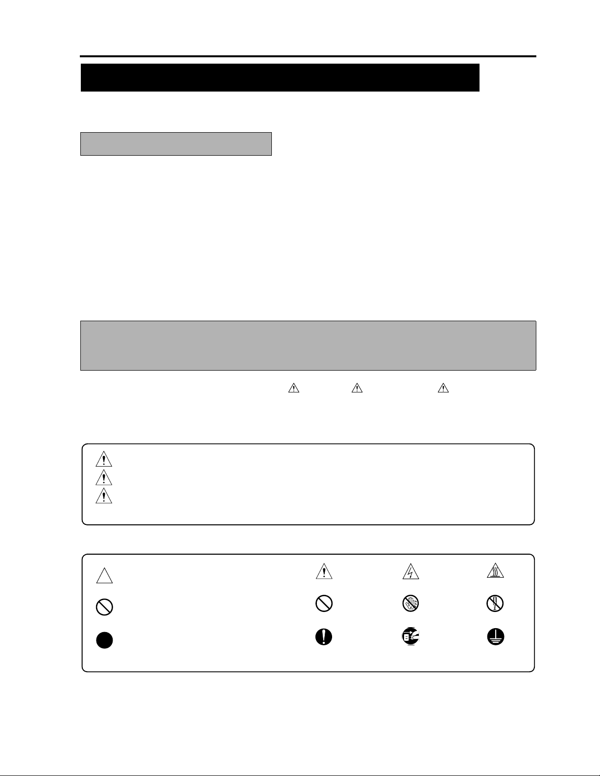
DESCRIPTION ITEMS FOR DANGER, WARNING AND
CAUTION
In this Service manual, each of three expressions “ DANGER”, “ WARNING”, and “ CAUTION” is defined
as follows together with a symbol mark to be used in a limited meaning.
When servicing the copier, the relevant works (disassembling, reassembling, adjustment, repair, maintenance,
etc.) need to be conducted with utmost care.
DANGER
WARNING
CAUTION
Symbols used for safety and important warning items are defined as follows:
:Precaution when using the copier.
:Prohibition when using the copier.
:Action having a high possibility of suffering death or serious injury
:Action having a possibility of suffering death or serious injury
:Action having a possibility of suffering a slight wound, medium trouble, and
property damage
General precaution Electric hazard High temperature
General prohibition Do not touch with wet hand Do not disassemble
:Direction when using the copier.
General instruction
S-1
Unplug
Ground/Earth
Page 14
SAFETY AND IMPORTANT WARNING ITEMS
SAFETY WARNINGS
1. MODIFICATIONS NOT AUTHORIZED BY MINOLTA
Minolta copiers are renowned for their high reliability. This reliability is achieved through high-quality design and
a solid service network.
Copier design is a highly complicated and delicate process where numerous mechanical, physical, and electrical
aspects have to be taken into consideration, with the aim of arriving at proper tolerances and safety factors. For
this reason, unauthorized modifications involve a high risk of degradation in performance and safety. Such mod-
ifications are therefore strictly prohibited. the points listed below are not exhaustive, but they illustrate the rea-
soning behind this policy.
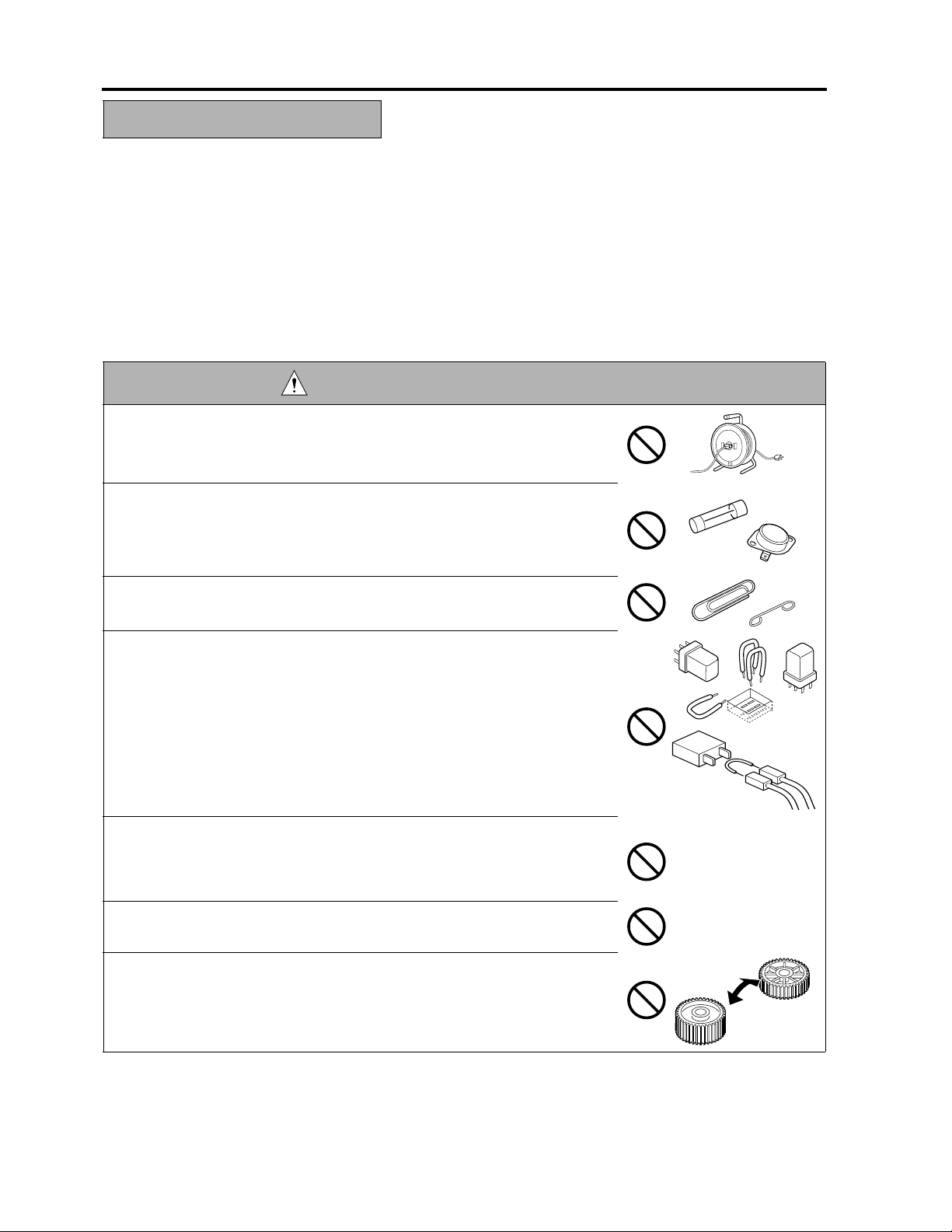
DANGER : PROHIBITED ACTIONS
• Using any cables or power cord not specified by Minolta.
• Using any fuse or thermostat not specified by Minolta. Safety will not be
assured, leading to a risk of fire and injury.
• Disabling fuse functions or bridging fuse terminals with wire, metal clips, sol-
der or similar object.
• Disabling relay functions (such as wedging paper between relay contacts)
• Disabling safety functions (interlocks, safety circuits, etc.) Safety will not be
assured, leading to a risk of fire and injury.
• Making any modification to the copier unless instructed by Minolta.
• Using parts not specified by Minolta.
S-2
Page 15
SAFETY AND IMPORTANT WARNING ITEMS
2. CHECKPOINTS WHEN PERFORMING ON-SITE SERVICE
Minolta copiers are extensively tested before shipping, to ensure that all applicable safety standards are met, in
order to protect the customer and customer engineer (hereafter called the CE) from the risk of injury. However,
in daily use, any electrical equipment may be subject to parts wear and eventual failure. In order to maintain
safety and reliability, the CE must perform regular safety checks.
2.1 Power Supply
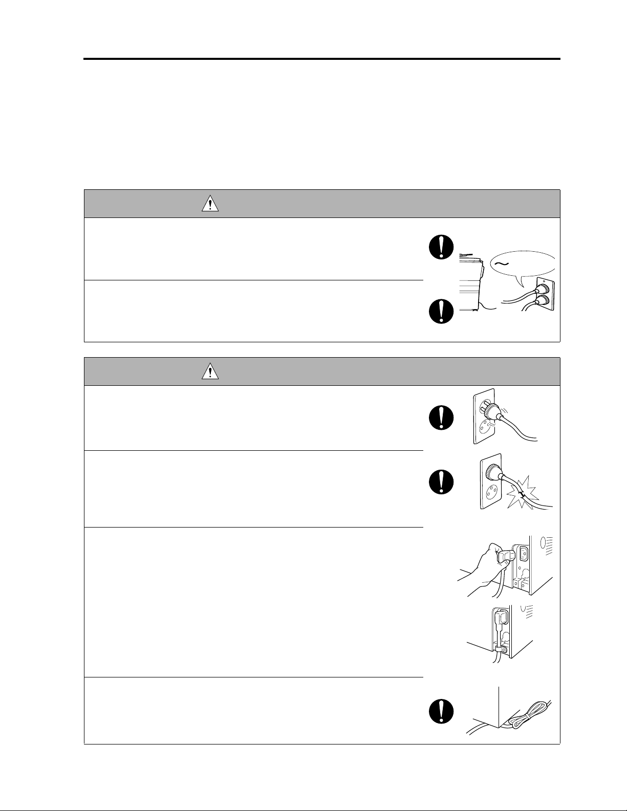
WARNING: Wall Outlet
• Check that mains voltage is as specified. Plug the power cord into the dedi-
cated wall outlet with a capacity greater than the maximum power consump-
tion.
If excessive current flows in the wall outlet, fire may result.
• If two or more power cords can be plugged into the wall outlet, the total load
must not exceed the rating of the wall outlet.
If excessive current flows in the wall outlet, fire may result.
kw
WARNING: Power Plug and Cord
• Make sure the power cord is plugged in the wall outlet securely.
Contact problems may lead to increased resistance, overheating, and the
risk of fire.
• Check whether the power cord is damaged. Check whether the sheath is
damaged.
If the power plug, cord, or sheath is damaged, replace with a new power
cord (with plugs on both ends) specified by Minolta. Using the damaged
power cord may result in fire or electric shock.
• When using the power cord (inlet type) that came with this copier, be sure to
observe the following precautions:
a. Make sure the copier-side power plug is securely inserted in the socket
on the rear panel of the copier.
Secure the cord with a fixture properly.
b. If the power cord or sheath is damaged, replace with a new power cord
(with plugs on both ends) specified by Minolta.
If the power cord (inlet type) is not connected to the copier securely, a
contact problem may lead to increased resistance, overheating, and risk
of fire.
• Check whether the power cord is not stepped on or pinched by a table and
so on.
Overheating may occur there, leading to a risk of fire.
S-3
Page 16
SAFETY AND IMPORTANT WARNING ITEMS
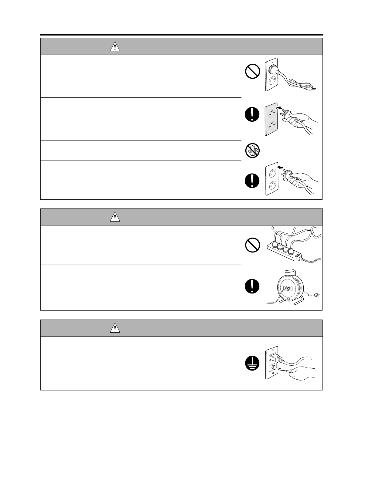
WARNING: Power Plug and Cord
• Do not bundle or tie the power cord.
Overheating may occur there, leading to a risk of fire.
• Check whether dust is collected around the power plug and wall outlet.
Using the power plug and wall outlet without removing dust may result in
fire.
• Do not insert the power plug into the wall outlet with a wet hand.
The risk of electric shock exists.
• When unplugging the power cord, grasp the plug, not the cable.
The cable may be broken, leading to a risk of fire and electric shock.
WARNING: Wiring
• Never use multi-plug adapters to plug multiple power cords in the same out-
let.
If used, the risk of fire exists.
• When an extension cord is required, use a specified one.
Current that can flow in the extension cord is limited, so using a too long
extension cord may result in fire.
Do not use an extension cable reel with the cable taken up. Fire may
result.
WARNING: Ground Lead
• Check whether the copier is grounded properly.
If current leakage occurs in an ungrounded copier, you may suffer electric
shock while operating the copier. Connect the ground lead to one of the
following points:
a. Ground terminal of wall outlet
b. Ground terminal for which Class D work has been done
S-4
Page 17
SAFETY AND IMPORTANT WARNING ITEMS
WARNING: Ground Lead
• Pay attention to the point to which the ground lead is connected.
Connecting the ground lead to an improper point such as the points listed
below results in a risk of explosion and electric shock:
a. Gas pipe (A risk of explosion or fire exists.)
b. Lightning rod (A risk of electric shock or fire exists.)
c. Telephone line ground (A risk of electric shock or fire exists in the case
of lightning.)
d. Water pipe or faucet (It may include a plastic portion.)
2.2. Installation Requirements
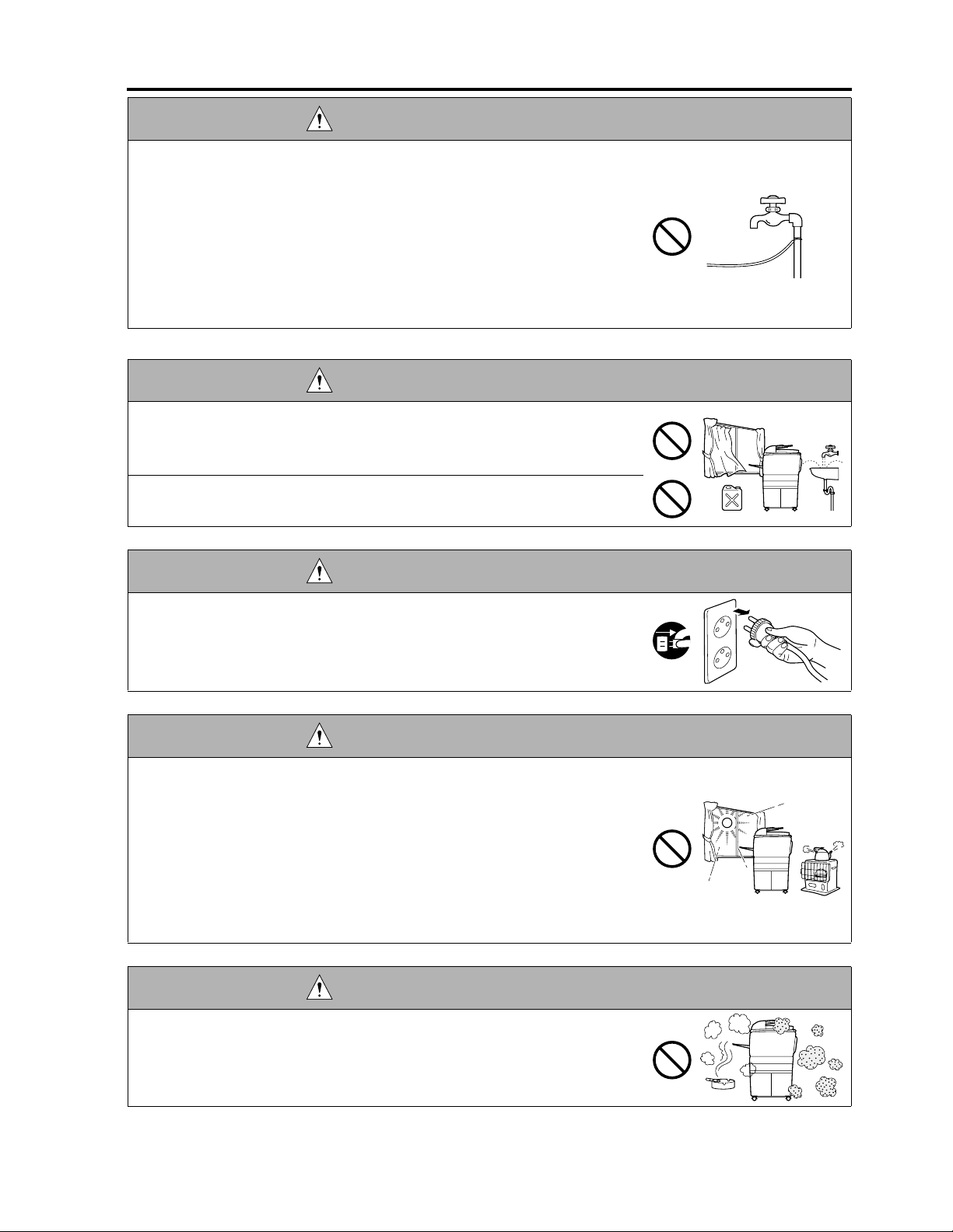
WARNING: Prohibited Installation Place
• Do not place the copier near flammable materials such as curtains or volatile
materials that may catch fire.
A risk of fire exists.
• Do not place the copier in a place exposed to water such as rain water.
A risk of fire and electric shock exists.
WARNING: Nonoperational Handling
• When the copier is not used over an extended period of time (holidays, etc.),
switch it off and unplug the power cord.
Dust collected around the power plug and outlet may cause fire.
CAUTION: Temperature and Humidity
• Do not place the copier in a place exposed to direct sunlight or near a heat
source such as a heater.
A risk of degradation in copier performance or deformation exists.
Do not place the copier in a place exposed to cool wind.
Recommended temperature and humidity are as follows:
Temperature: 10 °C to 30 °C
Humidity: 10 % to 80 % (no dew condensation)
Avoid other environments as much as possible.
CAUTION: Ventilation
• Do not place the copier in a place where there is much dust, cigarette smoke,
or ammonia gas.
Place the copier in a well ventilated place to prevent machine problems
and image faults.
S-5
Page 18
SAFETY AND IMPORTANT WARNING ITEMS
CAUTION: Ventilation
• The copier generates ozone gas during operation, but it is not sufficient to be
harmful to the human body.
If a bad smell of ozone is present in the following cases, ventilate the room.
a. When the copier is used in a poorly ventilated room
b. When taking a lot of copies
c. When using multiple copiers at the same time
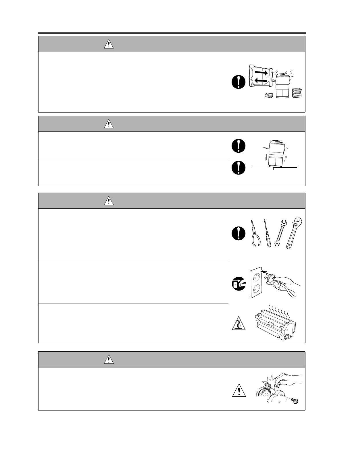
CAUTION: Vibration
• When installing the copier, read the Installation Guide thoroughly. Be sure to
install the copier in a level and sturdy place.
Constant vibration will cause problems.
• Be sure to lock the caster stoppers.
In the case of an earthquake and so on, the copier may slide, leading to a
injury.
CAUTION: Inspection before Servicing
• Before conducting an inspection, read all relevant documentation (Service
manual, technical notices, etc.) and proceed with the inspection following the
prescribed procedure in safety clothes, using only the prescribed tools. Do
not make any adjustment not described in the documentation.
If the prescribed procedure or tool is not used, the copier may break and a
risk of injury or fire exists.
• Before conducting an inspection, be sure to disconnect the power plugs from
the copier and options.
When the power plug is inserted in the wall outlet, some units are still pow-
ered even if the POWER switch is turned OFF. A risk of electric shock
exists.
• The area around the fixing unit is hot.
You may get burnt.
DANGER: Work Performed with the Copier Powered
• Take every care when making adjustments or performing an operation check
with the copier powered.
If you make adjustments or perform an operation check with the external
cover detached, you may touch live or high-voltage parts or you may be
caught in moving gears or the timing belt, leading to a risk of injury.
S-6
Page 19
SAFETY AND IMPORTANT WARNING ITEMS
DANGER: Work Performed with the Copier Powered
• Take every care when servicing with the external cover detached.
High-voltage exists around the drum unit. A risk of electric shock exists.
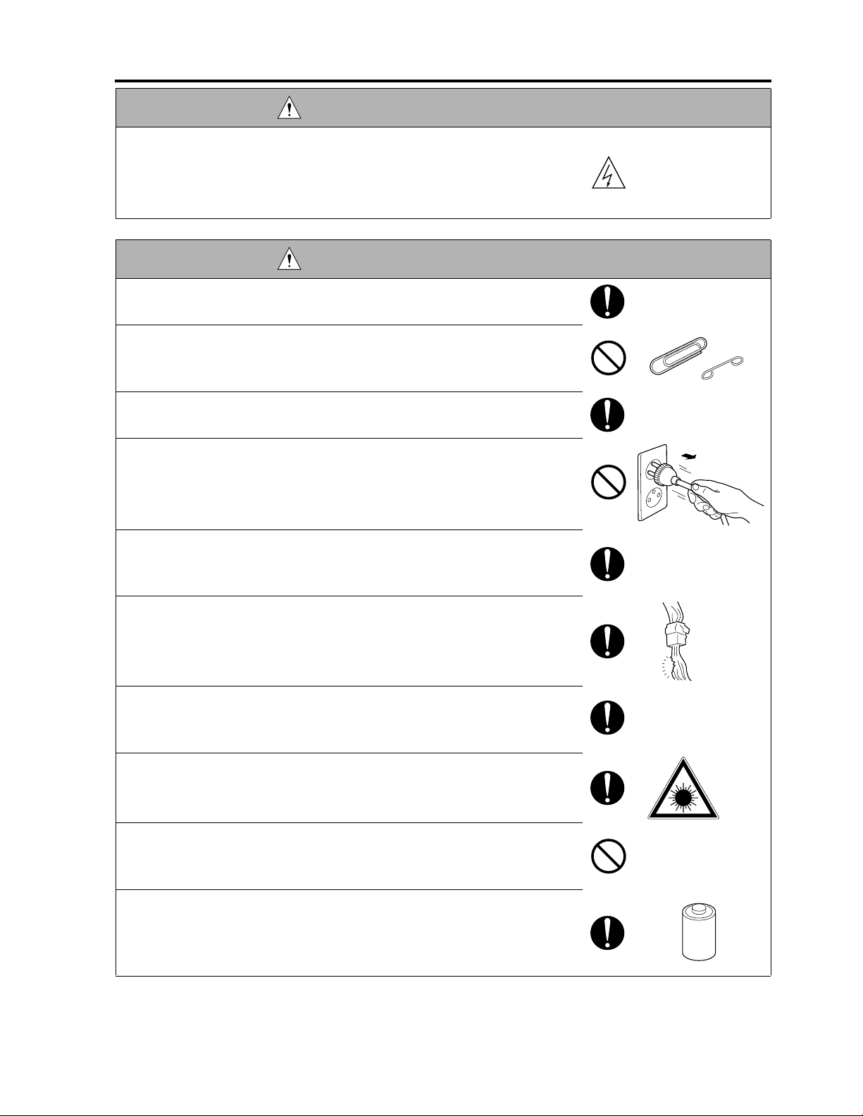
WARNING: Safety Checkpoints
• Check the exterior and frame for edges, burrs, and other damages.
The user or CE may be injured.
• Do not allow any metal parts such as clips, staples, and screws to fall into the
copier.
They can short internal circuits and cause electric shock or fire.
• Check wiring for squeezing and any other damage.
Current can leak, leading to a risk of electric shock or fire.
• When disconnecting connectors, grasp the connector, not the cable.
(Specifically, connectors of the AC line and high-voltage parts)
Current can leak, leading to a risk of electric shock or fire.
• Carefully remove all toner remnants and dust from electrical parts and elec-
trode units such as a charging corona unit.
Current can leak, leading to a risk of copier trouble or fire.
• Check high-voltage cables and sheaths for any damage.
Current can leak, leading to a risk of electric shock or fire.
• Check electrode units such as a charging corona unit for deterioration and
sign of leakage.
Current can leak, leading to a risk of trouble or fire.
• Before disassembling or adjusting the write unit incorporating a laser, make
sure that the power cord has been disconnected.
The laser light can enter your eye, leading to a risk of loss of eyesight.
• Do not remove the cover of the write unit. Do not supply power with the write
unit shifted from the specified mounting position.
The laser light can enter your eye, leading to a risk of loss of eyesight.
• When replacing a lithium battery, replace it with a new lithium battery speci-
fied in the Parts Guide Manual. Dispose of the used lithium battery using the
method specified by local authority.
Improper replacement can cause explosion.
S-7
Page 20
SAFETY AND IMPORTANT WARNING ITEMS
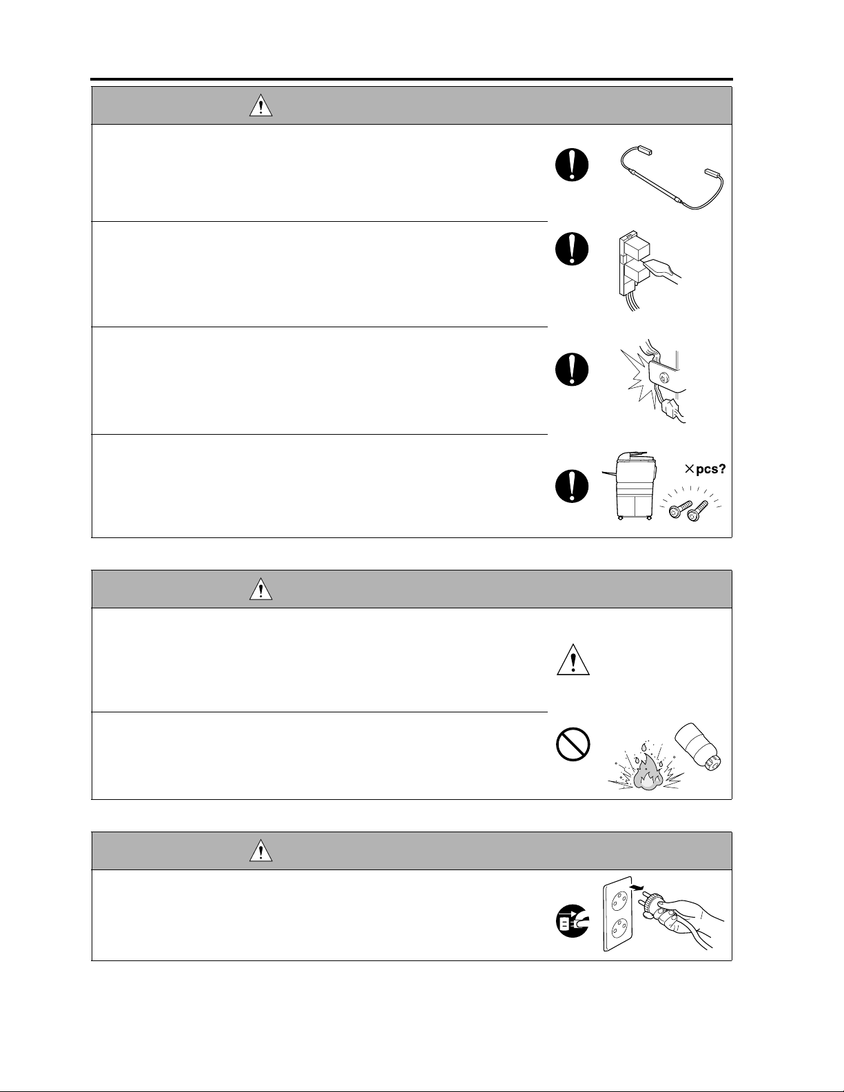
WARNING: Safety Checkpoints
• After replacing a part to which AC voltage is applied (e.g., optical lamp and
fixing lamp), be sure to check the installation state.
A risk of fire exists.
• Check the interlock switch and actuator for loosening and check whether the
interlock functions properly.
If the interlock does not function, you may receive an electric shock or be
injured when you insert your hand in the copier (e.g., for clearing paper
jam).
• Make sure the wiring cannot come into contact with sharp edges, burrs, or
other pointed parts.
Current can leak, leading to a risk of electric shock or fire.
• Make sure that all screws, components, wiring, connectors, etc. that were
removed for safety check and maintenance have been reinstalled in the orig-
inal location. (Pay special attention to forgotten connectors, pinched cables,
forgotten screws, etc.)
A risk of copier trouble, electric shock, and fire exists.
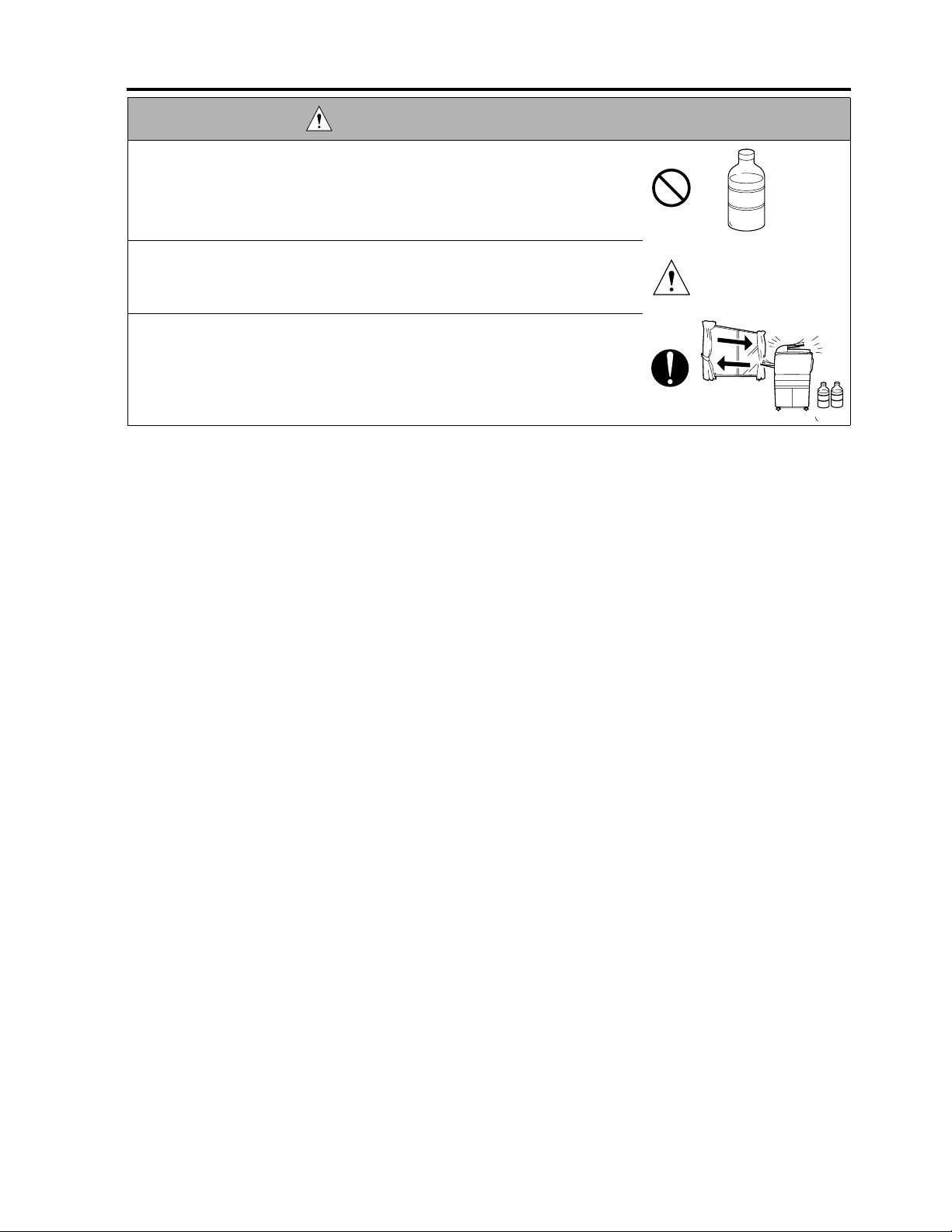
DANGER: HANDLING OF SERVICE MATERIALS
• Toner and developer are not harmful substances, but care must be taken not
to breathe excessive amounts or let the substances come into contact with
eyes, etc. It may be stimulative.
If the substances get in the eye, rinse with plenty of water immediately.
When symptoms are noticeable, consult a physician.
• Never throw the used cartridge and toner into fire.
You may be burned due to dust explosion.
DANGER : HANDLING OF SERVICE MATERIALS
• Unplug the power cord from the wall outlet.
Drum cleaner (isopropyl alcohol) and roller cleaner (acetone-based) are
highly flammable and must be handled with care. A risk of fire exists.
S-8
Page 21
SAFETY AND IMPORTANT WARNING ITEMS
DANGER : HANDLING OF SERVICE MATERIALS
• Do not replace the cover or turn the copier ON before any solvent remnants
on the cleaned parts have fully evaporated.
A risk of fire exists.
• Use only a small amount of cleaner at a time and take care not to spill any
liquid. If this happens, immediately wipe it off.
A risk of fire exists.
• When using any solvent, ventilate the room well.
Breathing large quantities of organic solvents can lead to discomfort.
3. MEASURES TO TAKE IN CASE OF AN ACCIDENT
• If an accident has occurred, the distributor who has been notified first must immediately take emergency
measures to provide relief to affected persons and to prevent further damage.
• If a report of a serious accident has been received from a customer, an on-site evaluation must be carried
out quickly and Minolta Corporation must be notified.
• To determine the cause of the accident, conditions and materials must be recorded through direct on-site
checks, in accordance with instructions issued by Minolta Corporation.
• For reports and measures concerning serious accidents, follow the regulations given in “Serious Accident
Report/Follow-up Procedures”.
4. CONCLUSION
• Safety of users and customer engineers depends highly on accurate maintenance and administration.
Therefore, safety can be maintained by the appropriate daily service work conducted by the customer
engineer.
• When performing service, each copier on the site must be tested for safety. The customer engineer must
verify the safety of parts and ensure appropriate management of the equipment.
S-9
Page 22

SAFETY AND IMPORTANT WARNING ITEMS
SAFETY INFORMATION
IMPORTANT INFORMATION
The Center for Devices and Radiological Health (CDRH) of the U.S. Food and Drug Administration implemented
regulations for laser products manufactured since August 1, 1976. Compliance is mandatory for products mar-
keted in the United States.
This copier is certified as a “Class 1” laser product under the U.S.
Department of Health and Human Services (DHHS) Radiation Performance Standard according to the Radiation
Control for Health and Safety Act of 1968. Since radiation emitted inside this copier is completely confined within
protective housings and external covers, the laser beam cannot escape during any phase of normal user opera-
tion.
S-10
Page 23
SAFETY AND IMPORTANT WARNING ITEMS
SAFETY CIRCUITS
This machine is provided with the following safety circuits to prevent machine faults from resulting in serious
accidents.
•
Overall protection circuit
•
Fixing upper lamp /1 (L2), Fixing upper lamp /2 (L3), Fixing lower lamp (L4) overheating prevention circuit
These safety circuits are described below to provide
the service engineer with a renewed awareness of
them in order to prevent servicing errors that may
impair their functions.
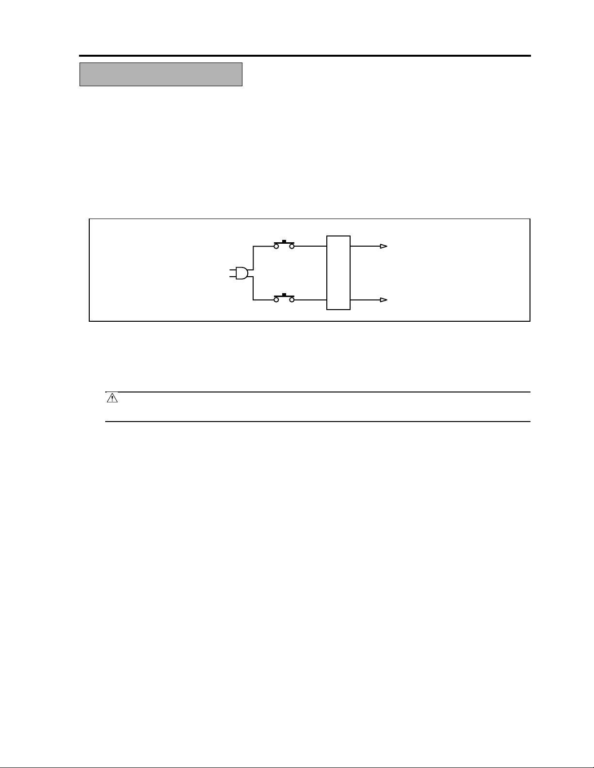
1. Overall protection circuit
CBR1
NF
CBR2
1.1 Protection by circuit breaker /1 (CBR1) and circuit breaker /2 (CBR2)
CBR1 and CBR2 interrupt the AC line instantaneously when an excessive current flows due to a short in
the AC line.
CAUTION:
The CBR1 and CBR2 functions must not be deactivated under any circumstances.
8050sf001
S-11
Page 24
SAFETY AND IMPORTANT WARNING ITEMS
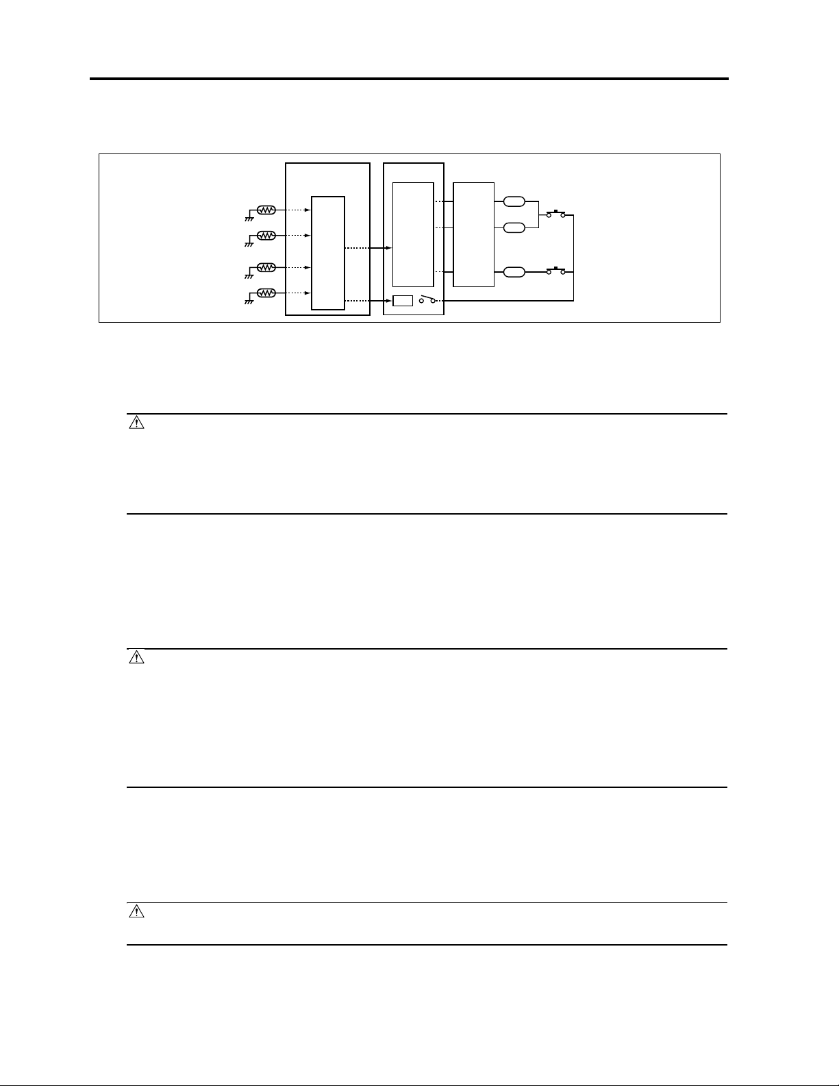
2. Fixing upper lamp /1 (L2), Fixing upper lamp /2 (L3), Fixing lower lamp (L4) overheating
prevention circuit
PRCB ACDB
TH1
TH3
TH2
TH4
Control
section
AC driver
section
RL1
RL1
FHCB
L2
TS1
L3
TS2
L4
8050sf002e
2.1 Protection by software
The output voltage from fixing temperature sensor /1 (TH1) and fixing temperature sensor /2 (TH2) is read
by the CPU. If this voltage is abnormal, L2, L3, and L4 are turned OFF by opening main relay (RL1).
CAUTION:
• The clearance between the fixing upper roller and TH1 and the clearance between the fixing
lower roller and TH2 must not be changed. When replacing them, make sure to comply with the
specified clearances.
• The RL1 function must not be deactivated under any circumstances.
2.2 Protection by the hardware circuit
The output voltages from fixing temperature sensor /1 (TH1), fixing temperature sensor /2 (TH2), fixing
temperature sensor /3 (TH3), and fixing temperature sensor /4 (TH4) are compared with the abnormality
judgment reference value in the comparator circuit. If the output voltage from TH1, TH2, TH3, or TH4
exceeds the reference value, L2, L3, and L4 are turned OFF by opening RL1.
CAUTION:
• The clearance between the fixing upper roller and TH1 and the clearance between the fixing
lower roller and TH2 must not be changed. When replacing them, make sure to comply with the
specified clearances.
• Periodically check the contact between the fixing upper roller and TH3 and the contact
between the fixing lower roller and TH4, and replace them if any abnormality is detected.
• The RL1 function must not be deactivated under any circumstances.
2.3 Protection by thermostat /1 (TS1) and thermostat /2 (TS2)
When the temperature of the fixing upper roller exceeds the specified value, TS1 is turned OFF, thus inter-
rupting the power to L2 and L3 directly. When the temperature of the fixing lower roller exceeds the speci-
fied value, TS2 is turned OFF, thus interrupting the power to L4 directly.
CAUTION:
Do not use any other electrical conductor in place of TS1 and TS2.
S-12
Page 25
SAFETY AND IMPORTANT WARNING ITEMS
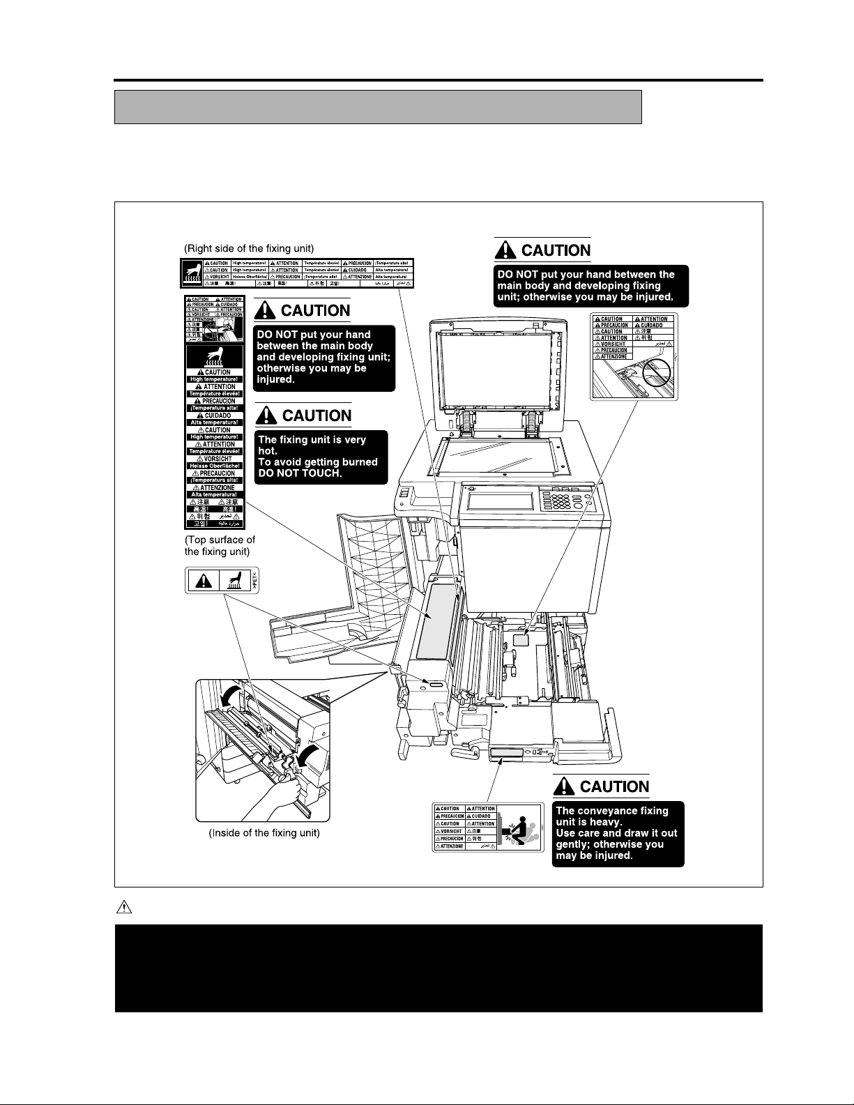
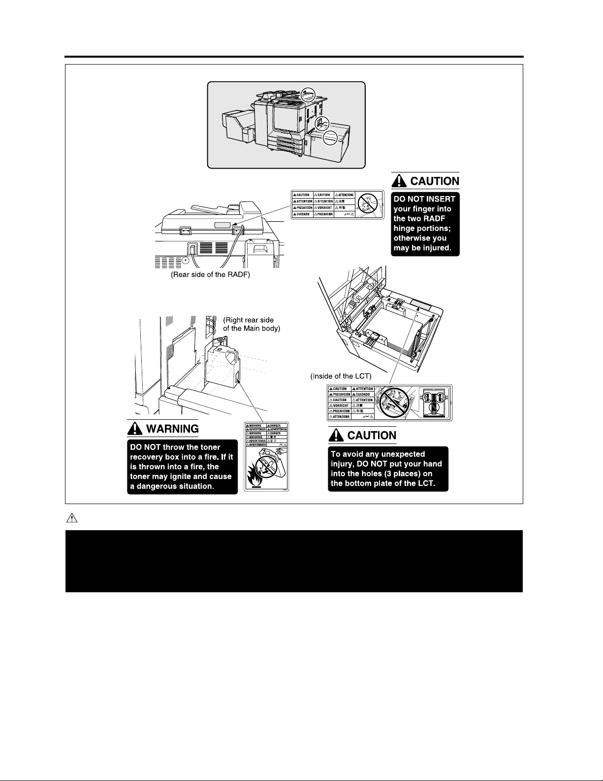
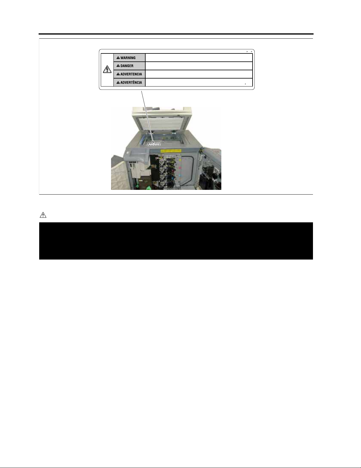
INDICATION OF WARNING ON THE MACHINE
Caution labels shown below are attached in some areas on/in the machine.
When accessing these areas for maintenance, repair, or adjustment, special care should be taken to avoid
burns and electric shock.
CAUTION
Please adhere to all caution labels to avoid burns or injury.
S-13
8050sf003e
Page 26
SAFETY AND IMPORTANT WARNING ITEMS
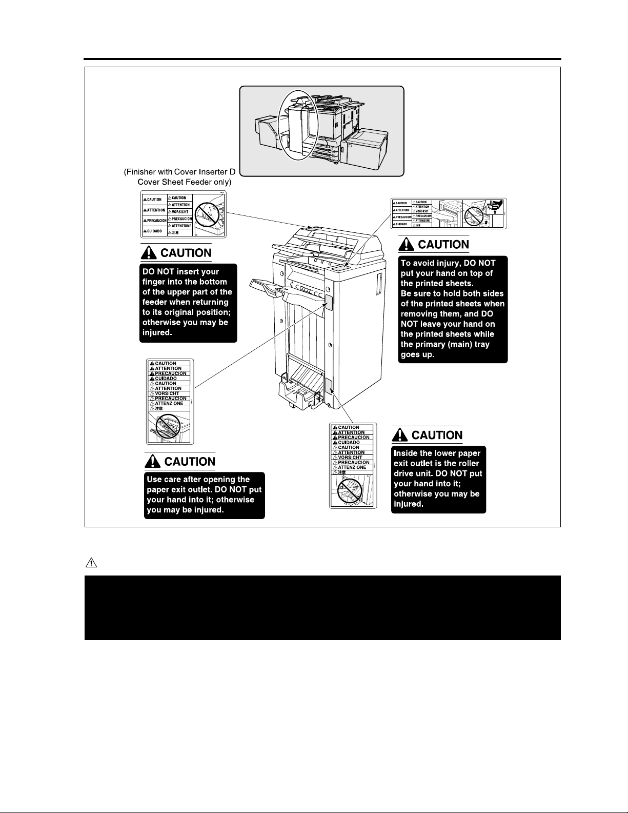
CAUTION
-
Please adhere to all caution labels to avoid burns or injury.
S-14
8050sf004e
Page 27
SAFETY AND IMPORTANT WARNING ITEMS
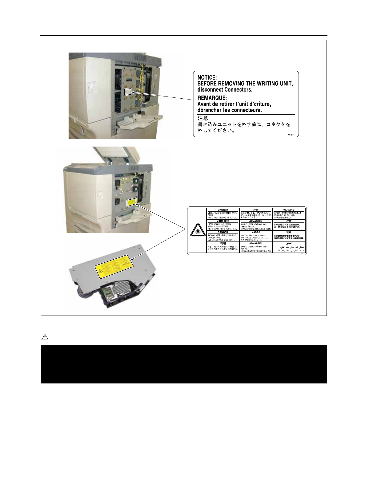
CAUTION
-
Please adhere to all caution labels to avoid burns or injury.
S-15
8050sf005e
Page 28
SAFETY AND IMPORTANT WARNING ITEMS
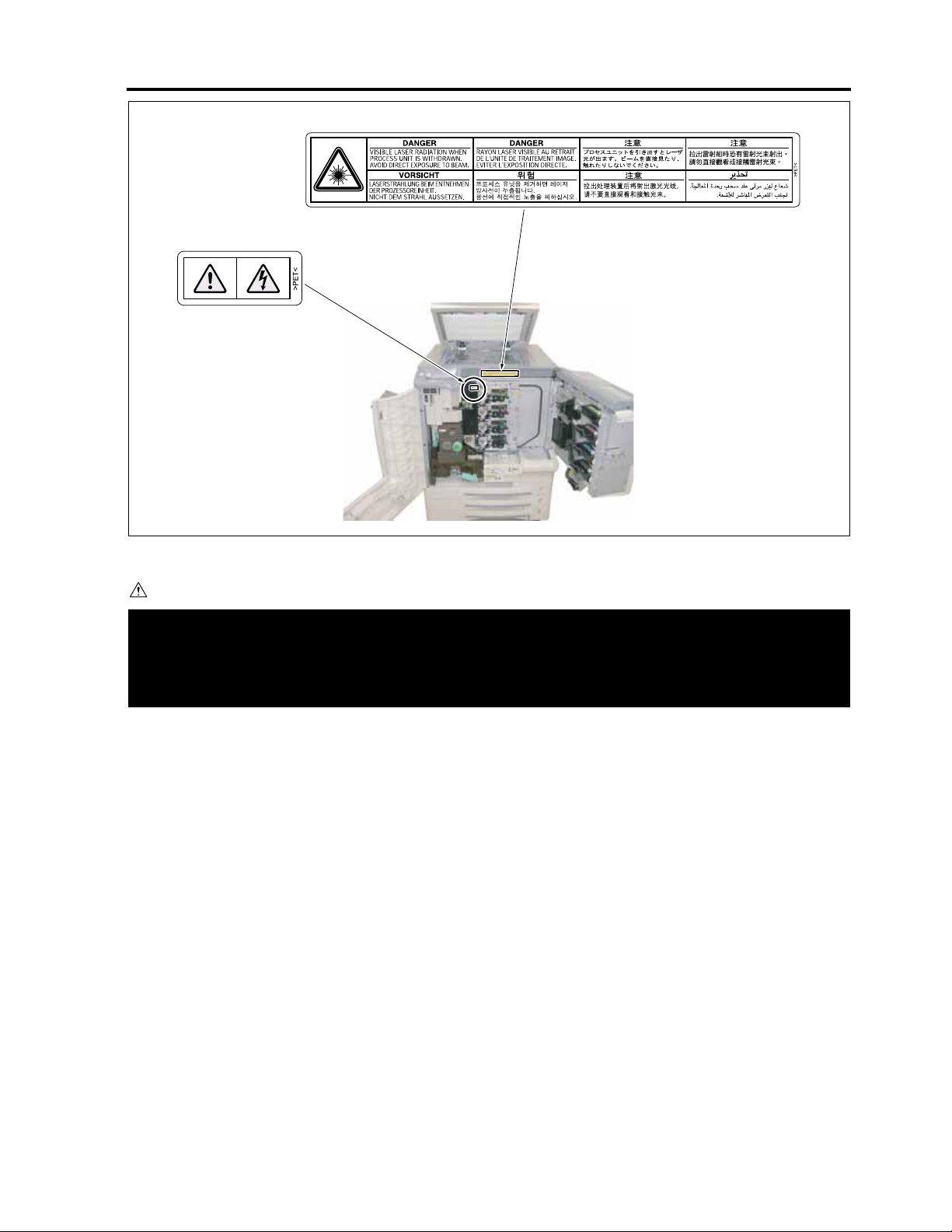
CAUTION
-
Please adhere to all caution labels to avoid burns or injury.
S-16
8050sf006e
Page 29
SAFETY AND IMPORTANT WARNING ITEMS
8050sf007e
CAUTION
-
Please adhere to all caution labels to avoid burns or injury..
S-17
Page 30
SAFETY AND IMPORTANT WARNING ITEMS
Unplug the machine before removing platen glass.
Debrancher le copieur avant de retirer la vitre d'exposition.
Desenchufe la maquina antes de quitar el vidrio.
Desconecte a unidade da tomada antes de remover o vidro de exposicao.
PS
~
8050sf008e
CAUTION
-
Please adhere to all caution labels to avoid burns or injury.
S-18
Page 31

CF5001 Field Service Ver.1.0 Sep 2003 EXTERIOR
I DISASSEMBLY/ASSEMBLY
Caution:
• Make sure the power cord of the copier is
unplugged from the power outlet before dis-
assembly or assembly.
1. EXTERIOR
1.1 Replacing the dust filter /2
A. Periodically replaced parts/cycle
• Dust filter /2: Every 100,000 copies
B. Procedure
1. Loosen 2 screws [1] and remove the filter cover
[2].
[1]
I DIS./ASSEMBLY
2. Pull out the dust filter /2 [2] from the filter cover
[1].
3. Reinstall the above parts following the removal
steps in reverse.
1-1
[1]
[2]
[2]
8050ma3001
8050ma3002
Page 32
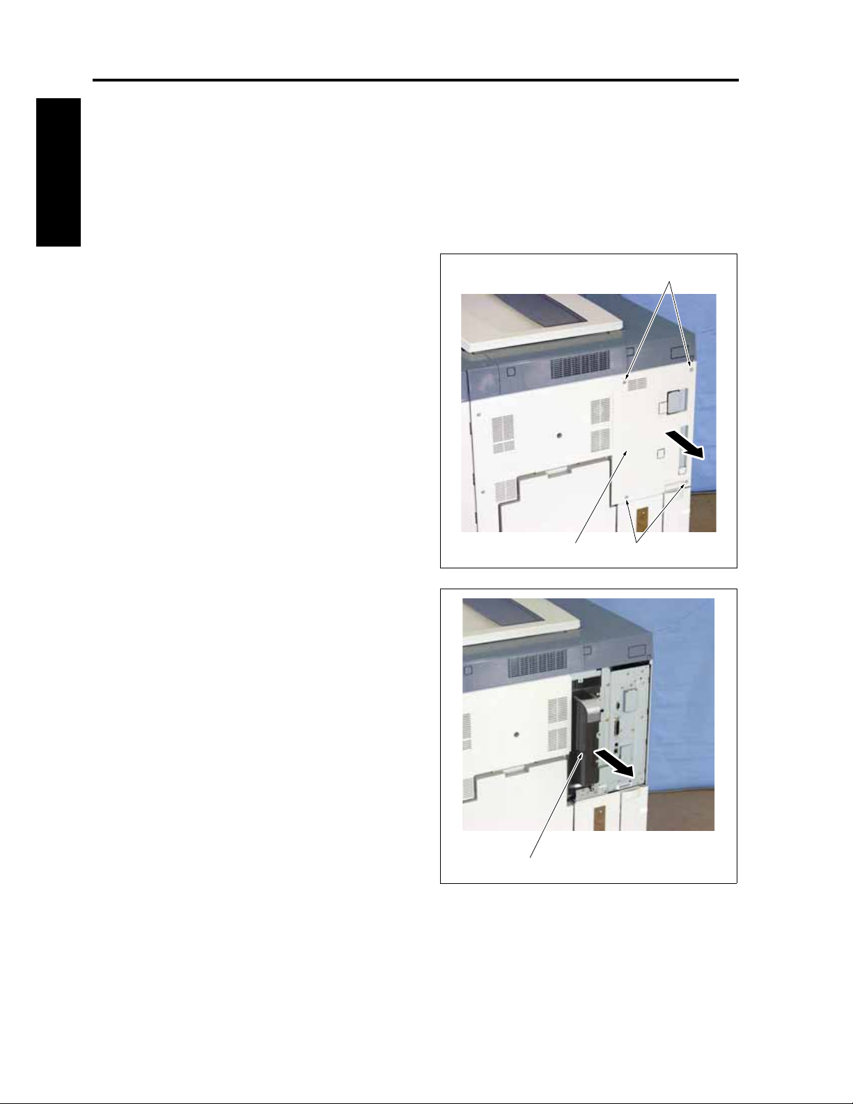
EXTERIOR CF5001 Field Service Ver.1.0 Sep 2003
1.2 Replacing the dust filter /1
and the ozone filter /1
A. Periodically replaced parts/cycle
• Dust filter /1: Every 100,000 copies
• Ozone filter /1: Every 100,000 copies
I DIS./ASSEMBLY
B. Procedure
1. Loosen 4 screws [1] and remove the side cover /
2 [2].
[1]
2. Pull out the filter replacement duct [1].
[1]
[1][2]
8050ma3004
8050ma3005
1-2
Page 33
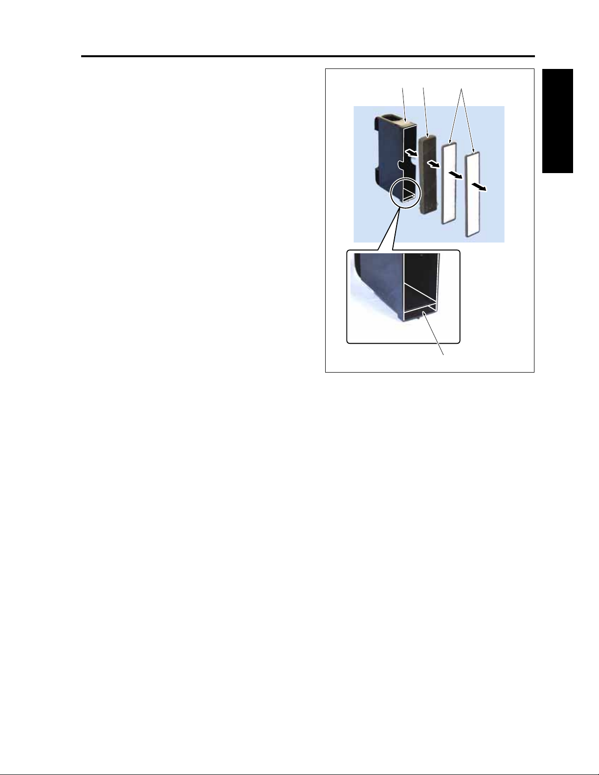
CF5001 Field Service Ver.1.0 Sep 2003 EXTERIOR
3. Remove the 2 dust filters /1 [2] and the ozone fil-
ter /3 [3] from the filter replacement duct [1].
[1] [3] [2]
4. Reinstall the above parts following the removal
steps in reverse.
Note:
• When reinstalling the ozone filter /1, be care-
ful not snap and fracture it.
• When reinstalling the dust filter /1, be sure to
press it against the stopper section [4] of the
filter replacement duct.
I DIS./ASSEMBLY
[4]
8050ma3006
1-3
Page 34
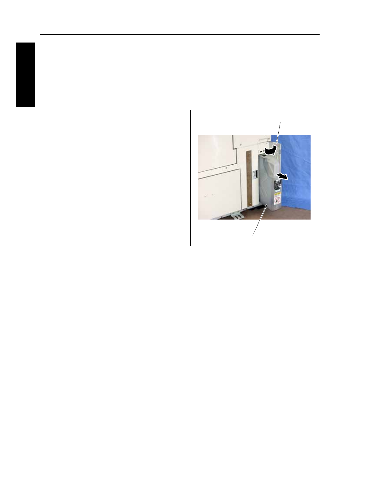
EXTERIOR CF5001 Field Service Ver.1.0 Sep 2003
1.3 Replacing the toner collection box
A. Periodically replaced parts/cycle
• Toner collection box: Every 50,000 copies (to be
replaced by the user)
I DIS./ASSEMBLY
B. Procedure
1. Open the toner collection door [1] and pull out
the toner collection box [2].
[1]
[2]
8050ma3007
1-4
Page 35
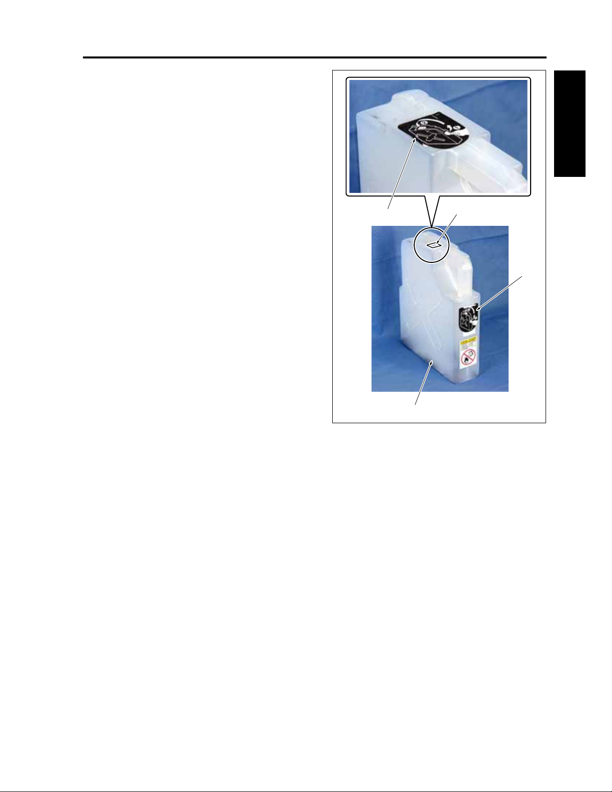
CF5001 Field Service Ver.1.0 Sep 2003 EXTERIOR
2. Peel the label [2] off the toner collection box [1]
and plug the entrance of the toner collection box
[1].
3. Reinstall the above parts following the removal
steps in reverse.
I DIS./ASSEMBLY
[2]
[1]
[3]
[2]
8050ma3008
1-5
Page 36
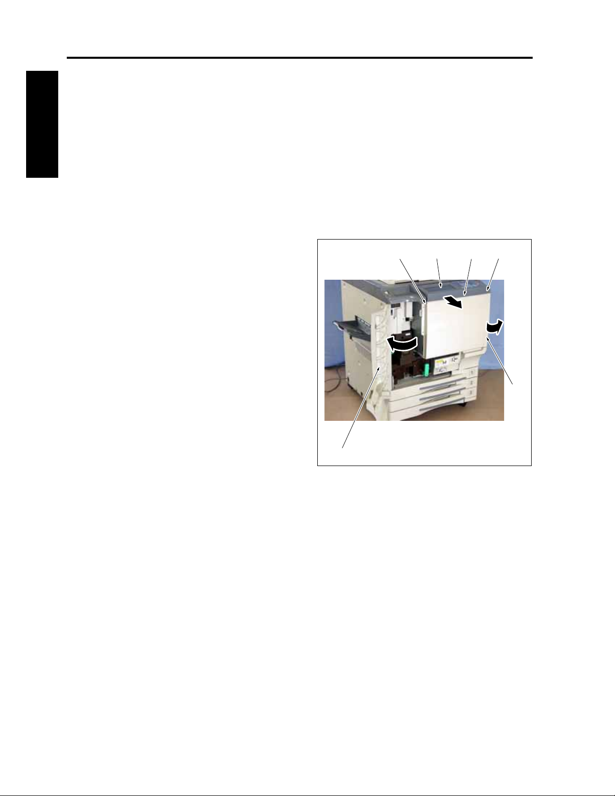
EXTERIOR CF5001 Field Service Ver.1.0 Sep 2003
1.4 Angle adjustment of the
operation board
Note:
• The operation board can be set at the two
steps of 7 and 18 degrees depending on the
I DIS./ASSEMBLY
front cover /2 provided or not provided.
When the front cover /2 provided: 7 degrees
When the front cover /2 not provided: 18
degrees
A. Procedure
1. Open the front door [1] and the toner supply
door [2].
2. Remove 2 screws [3] and release the fixing of
the operation board [4].
3. With the operation board raised up, remove the
front cover /2 [5] (when the angle is changed
from 7 to 18 degrees).
4. Fasten the operation board [4] with 2 screws [3].
5. Close the front door [1] and the toner supply
door [2].
[4][3] [5] [3]
Note:
• When changing the angle of the operation
board from 18 to 7 degrees, install the front
cover /2 by following Step 3.
[1]
[2]
8050ma3009
1-6
Page 37
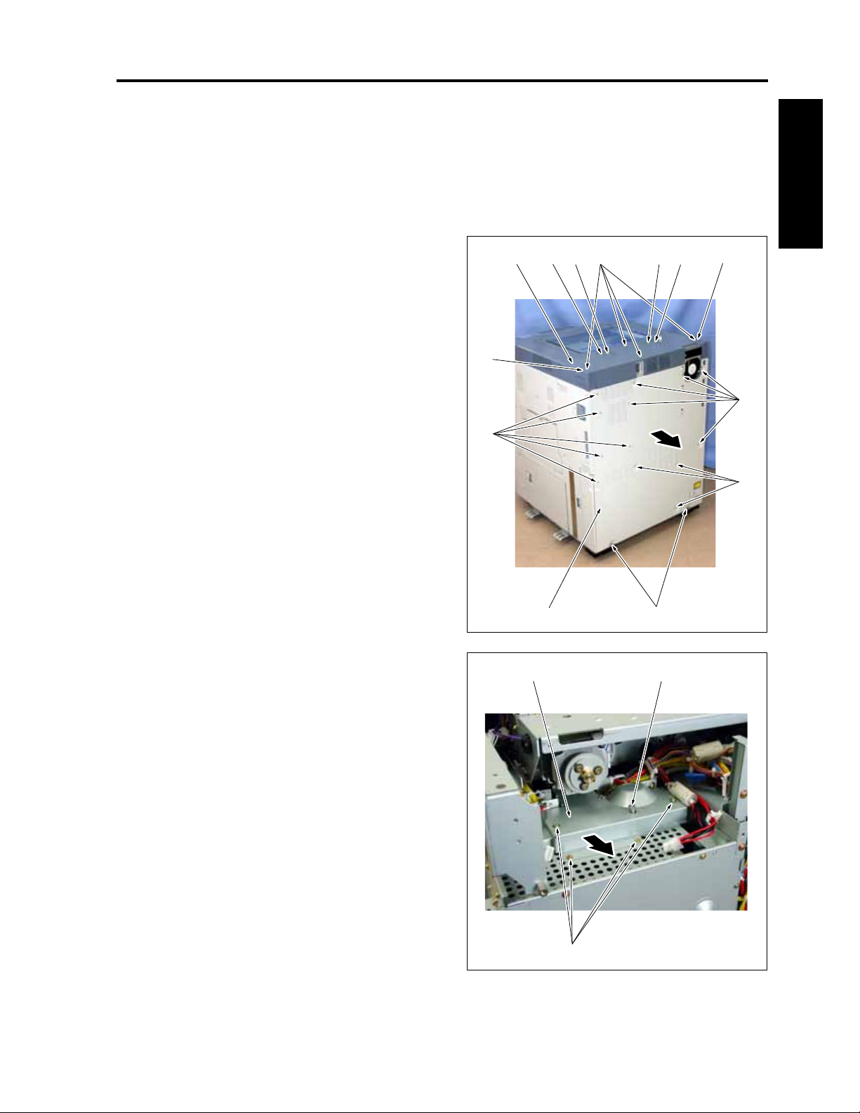
CF5001 Field Service Ver.1.0 Sep 2003 EXTERIOR
1.5 Removing and reinstalling the main board unit
A. Procedure
1. Remove the platen cover.
2. Remove the filter cover. (See "1.1 Replacing the
dust filter /2.")
3. Loosen 2 screws [1], remove 13 screws [2], and
then remove the rear cover [3].
4. Remove the side cover /2. (See "1.2 Replacing
the dust filter /1 and the ozone filter /1.")
5. Remove the screws [5], one for each, and then
remove the 2 original cover supports [6].
6. Remove 2 caps [4].
7. Remove 4 screws [7] and then remove the scan-
ner cover /R [8].
[8] [7] [6] [5] [4][6] [5]
[4]
[2]
[2]
I DIS./ASSEMBLY
8. Remove the special screw [1].
9. Remove 4 screws [2] and then remove the
board seal plate /2 [3].
[2]
[1][3]
[1][3]
8050ma3010
1-7
[2]
8050ma3011
Page 38
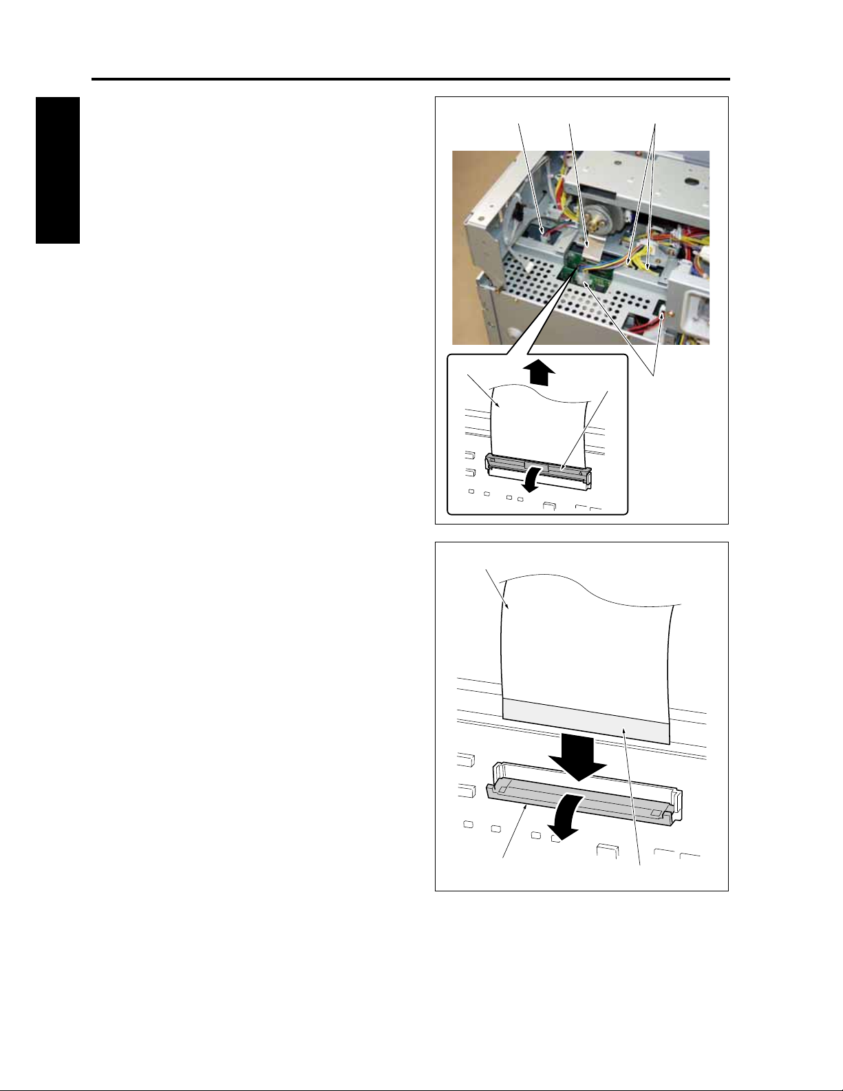
EXTERIOR CF5001 Field Service Ver.1.0 Sep 2003
10. Remove 5 connectors [1].
11. With the lock lever [2] brought down this side,
[1] [3] [1]
release the lock and pull out the ribbon cable [3].
I DIS./ASSEMBLY
[3]
[2]
[1]
Note:
• Move the lock lever [1] forward, then insert the
ribbon cable [2] firmly into the connector
while ensuring that the conductive face of the
ribbon cable [3] is positioned on the opposite
side of the lock lever.
[2]
[1]
8050ma3012
[3]
1-8
Page 39
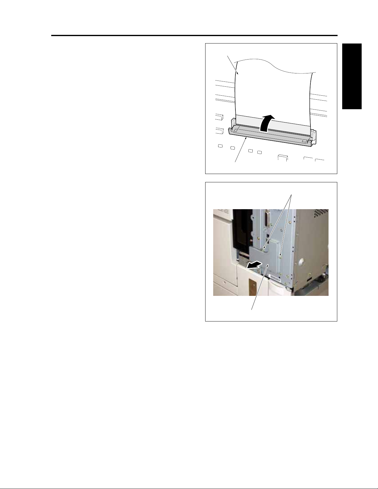
CF5001 Field Service Ver.1.0 Sep 2003 EXTERIOR
• Then with the lock lever [1] brought back to its
original position, lock the ribbon cable [2].
[2]
[1]
I DIS./ASSEMBLY
12. Remove 2 screws [1] and then remove the
board seal plate /4 [2].
[2]
[1]
8050ma3013
1-9
Page 40
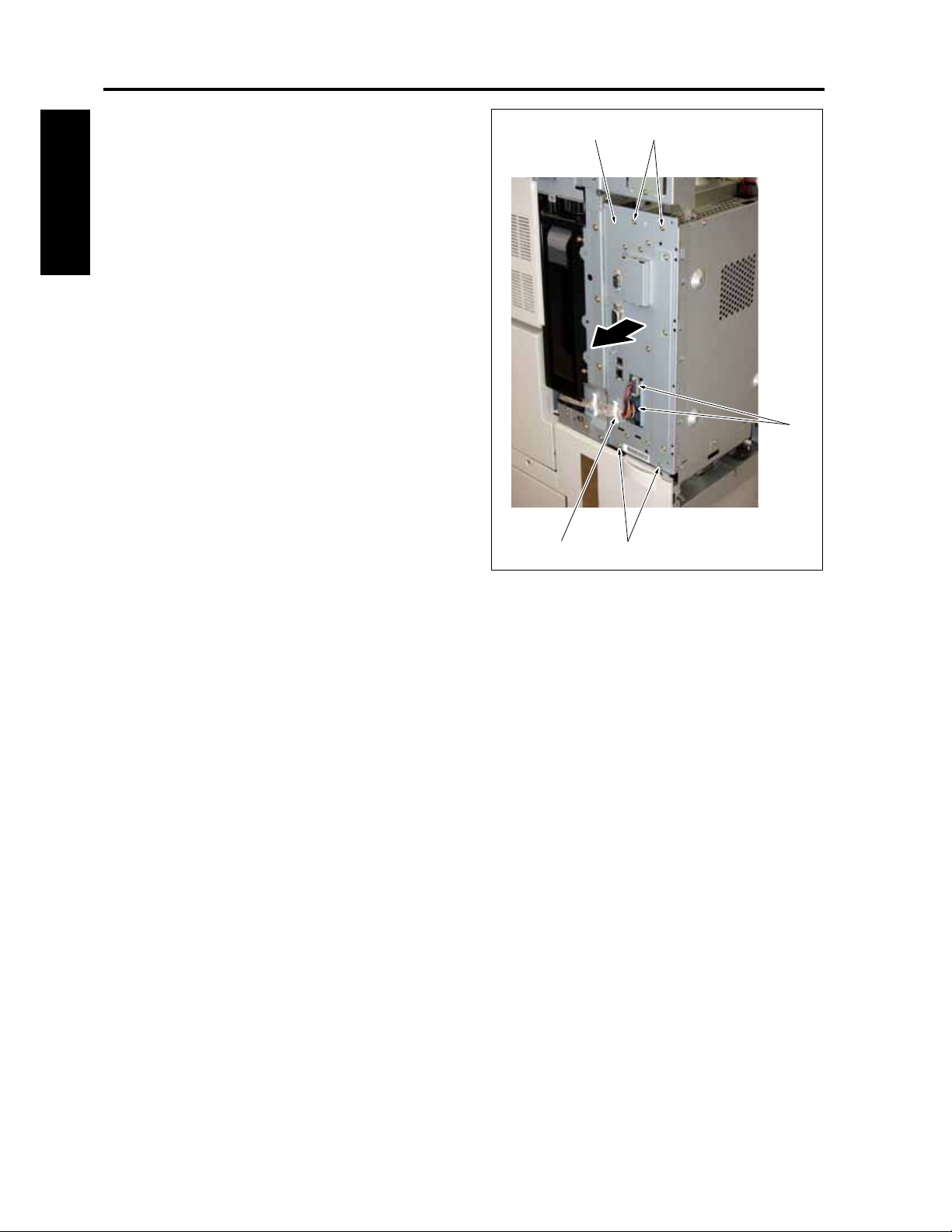
EXTERIOR CF5001 Field Service Ver.1.0 Sep 2003
13. Remove a bracket cable clamp [1].
14. Remove 2 connectors [2].
[3][4]
15. Remove 4 screws [3] and then remove the main
board unit [4].
16. Reinstall the above parts following the removal
steps in reverse.
I DIS./ASSEMBLY
Note:
• When removing or reinstalling the main board
unit, be careful that the battery on the memory
board (MB) does not touch with the frame.
[2]
[3][1]
8050ma3014
1-10
Page 41
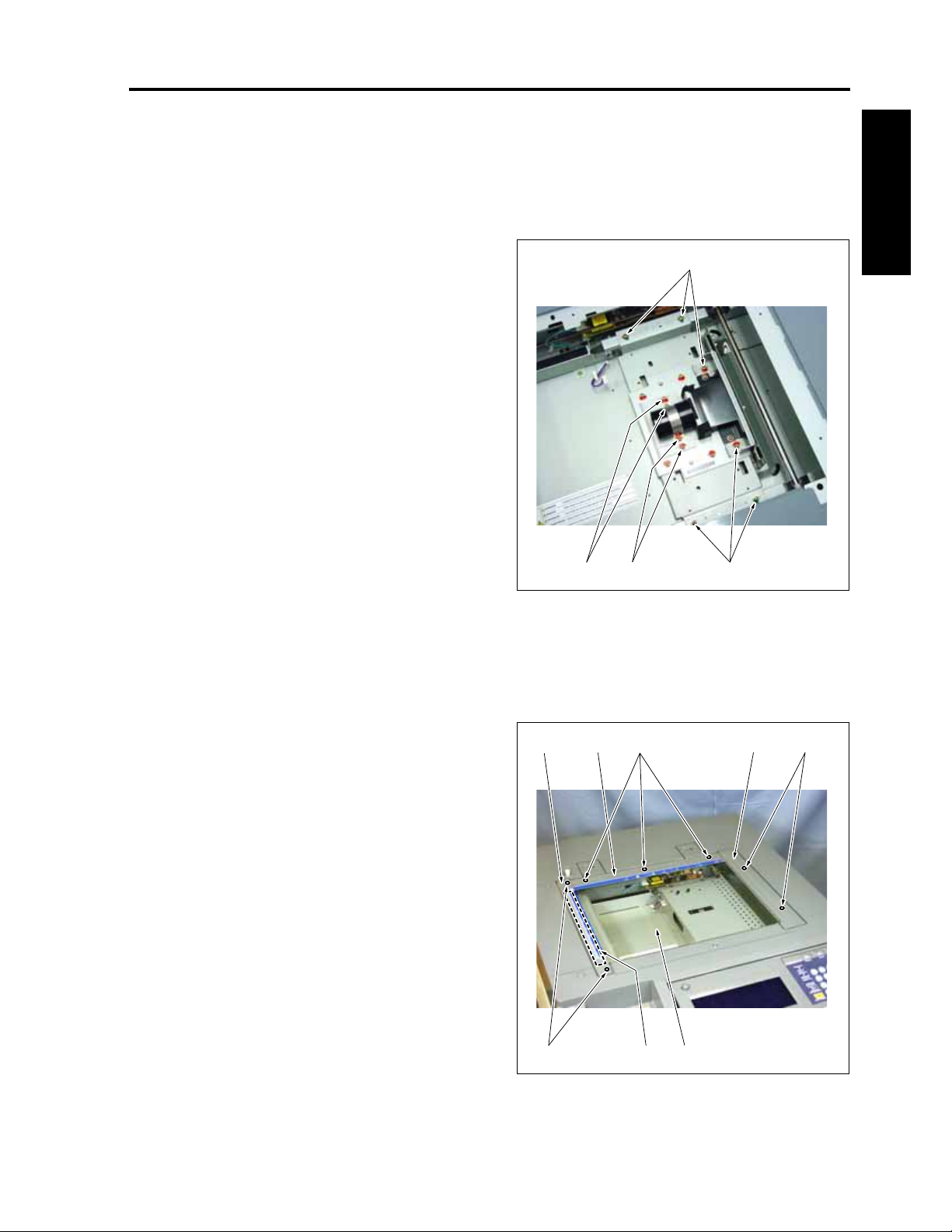
CF5001 Field Service Ver.1.0 Sep 2003 SCANNER
2. SCANNER
2.1 Screws that must not be removed
Note:
Screws that have been paint-locked are not
allowed to be removed. So, be careful not to
remove them.
[1]
I DIS./ASSEMBLY
2.2 Removing and reinstalling the platen glass
A. Procedure
1. Remove 3 screws [1] and then remove the origi-
nal positioning plate /R [2].
2. Remove 2 screws [3] and then remove the origi-
nal positioning plate /L [4].
3. Remove 2 screws [5] and the remove the scan-
ner cover /M [6].
4. Remove the platen glass [7].
5. Reinstall the above parts following the removal
steps in reverse.
Note:
• Be sure to reinstall the platen glass with its
white reference plate [8] up.
[1][1][1]
8050ma3015
[5][1] [6][4] [2]
1-11
[7][3] [8]
8050ma3016
Page 42

SCANNER CF5001 Field Service Ver.1.0 Sep 2003
2.3 Removing and reinstalling the CCD unit
A. Procedure for removal
1. Remove the platen glass. (See "2.2 Removing
and reinstalling the platen glass.")
I DIS./ASSEMBLY
2. Remove the connector [1].
3. Remove 9 screws [2] and then remove the CCD
cover [3].
4. Remove the screw [4] and then remove the rib-
bon cable cover [5].
[4] [5] [3]
5. With the lock lever [1] brought down, release the
lock and pull out the ribbon cable [2].
Note:
• Move the lock lever [1] downward, then insert
the ribbon cable [2] firmly into the connector
while ensuring that the conductive face of the
ribbon cable is positioned on the opposite
side of the lock lever.
• Then bring the lock lever back to its original
position, lock the ribbon cable.
1-12
[2][1]
[2][1]
8050ma3141
8050ma3142
Page 43

CF5001 Field Service Ver.1.0 Sep 2003 SCANNER
6. Remove 4 screws [1] and then remove the CCD
unit [2].
[1] [2]
Note:
• Be careful not to remove screws other than
those mentioned above. Otherwise, it
becomes necessary to make all sort of optical
adjustments which cannot be handled in the
field.
• Be careful not to touch the lens. This may
result in poor images.
7. Reinstall the above parts following the removal
steps in reverse.
[1]
8050ma3143
I DIS./ASSEMBLY
1-13
Page 44

SCANNER CF5001 Field Service Ver.1.0 Sep 2003
2.4 Removing and reinstalling the exposure unit
A. Procedure for removal
1. Remove the slit glass. (See "2.2 Removing and
reinstalling the slit glass.")
I DIS./ASSEMBLY
2. Open the toner supply section. (See "5.1 Open-
ing and closing of the toner supply section.")
3. Remove 2 caps [2].
4. Remove 6 screws [1].
5. After removing the relay connector [4] with the
scanner cover /F [3] shifted to the front side
once, remove the scanner cover /F [3].
[1][2] [2]
[3]
[4]
[1]
8050ma3017
1-14
Page 45

CF5001 Field Service Ver.1.0 Sep 2003 SCANNER
6. Remove 2 screws [1] and release the fixing of
the exposure unit [2].
[2][5][1] [4]
7. Rotate the exposure unit [2] while holding it hor-
izontally, pull it up and place it upon the scanner
room [6].
[3]
8050ma3018
[6] [5]
[1]
I DIS./ASSEMBLY
8. Remove the connector [1].
9. Remove the screw [2] and release the cable [4]
from the cable holder [3].
10. Remove the exposure unit [5].
[4]
[5][1][2] [3]
8050ma3019
1-15
Page 46

SCANNER CF5001 Field Service Ver.1.0 Sep 2003
B. Procedure for reinstallation
1. Set the exposure unit [1] into the main body.
2. Move the V-mirror unit [2] to the paper exit side,
[2] [1][4]
and pass an optical positioning jig [3] through
each of the exposure unit [1] and the V-mirror
unit [2] from the front side.
I DIS./ASSEMBLY
Note:
• When reinstalling the exposure unit, be sure
to use the optical positioning jig.
3. Fasten the exposure unit [1] with 2 screws [4].
4. Remove 2 optical positioning jigs [3].
5. For the subsequent steps, reinstall the parts fol-
lowing the removal steps in reverse.
[3]
[4]
8050ma3020
1-16
Page 47

CF5001 Field Service Ver.1.0 Sep 2003 SCANNER
2.5 Removing and reinstalling the exposure lamp
A. Procedure
1. Remove the exposure unit. (See "2.4 Removing
and reinstalling the exposure unit.")
2. Cut the binding band [1] and release the fixing
of the cable [2].
3. Remove 2 screws [3] and then remove the HP
detection plate [4].
4. Remove 2 screws [5] and then remove L1 (expo-
sure lamp) [6].
5. Reinstall the above parts following the removal
steps in reverse.
[6][1] [3]
I DIS./ASSEMBLY
[2] [4] [5]
8050ma3021
1-17
Page 48
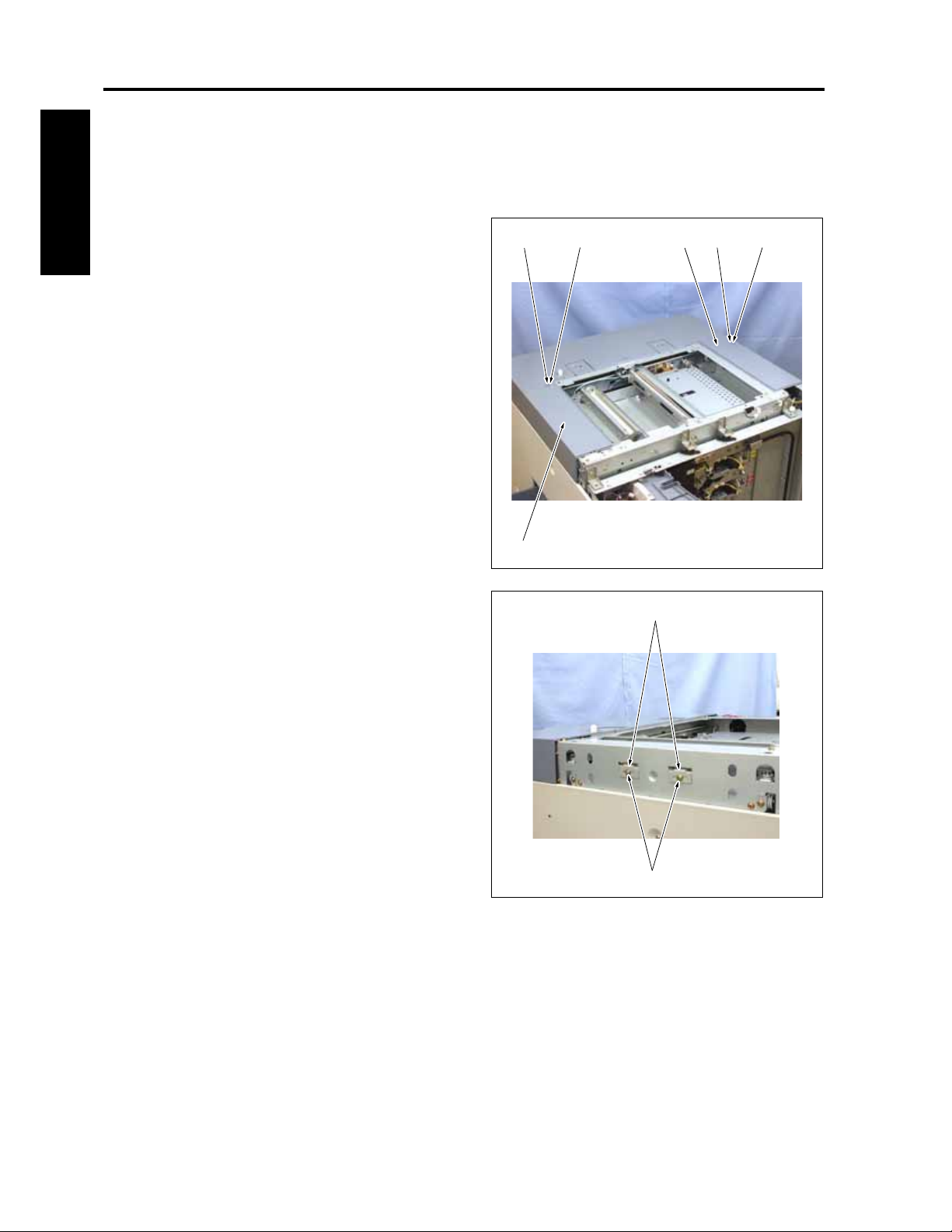
SCANNER CF5001 Field Service Ver.1.0 Sep 2003
2.6 Removing the scanner wire
A. Procedure
1. Remove the exposure unit. (See "2.4 Removing
and reinstalling the exposure unit.")
2. Remove 2 caps [1].
I DIS./ASSEMBLY
3. Remove the screw [2] and remove the scanner
cover /R [3].
4. Remove the screw [4] and remove the scanner
cover /L [5].
[1] [4] [1][3] [2]
5. Loosen the screws [1], one for each, and
release the fixing of two spring fixing plates [2].
[5]
[2]
[1]
8050ma3022
8050ma3023
1-18
Page 49
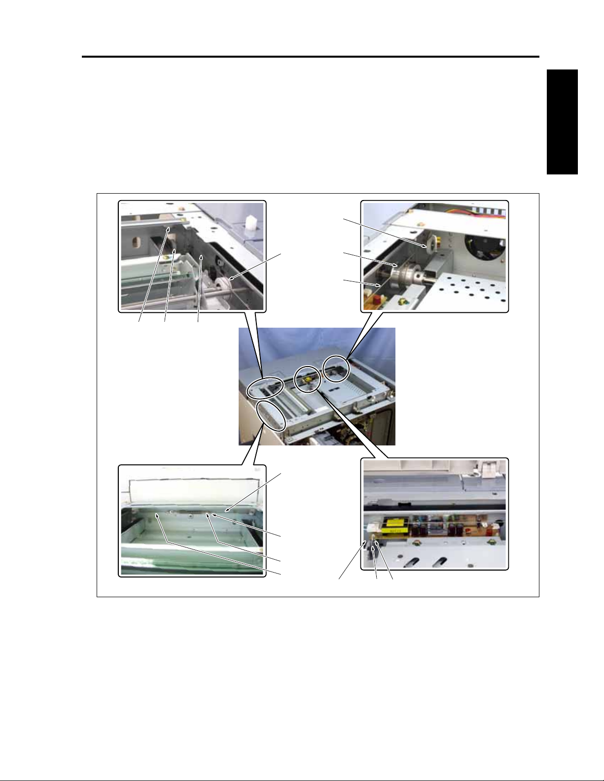
CF5001 Field Service Ver.1.0 Sep 2003 SCANNER
6. Remove the wire terminal [3] of the scanner wire
/R [2] from the spring fixing plate [1], and then
remove the scanner wire /R [2] in the order of
the pulley /3 [4], the outside of the V-mirror pul-
ley [5] and the pulley /2 [6].
7. Remove the metal bead [8] of the scanner wire /
R [2] from the wire stopper [7], and then remove
the scanner wire /R [2] in the order of the inside
of the V-mirror pulley [5] and the pulley /1 [9].
[5]
[3][6][4]
8. Remove the scanner wire /R [2] from the drive
pulley [10].
9. Remove the scanner wire /F [11] by following
Steps 5 to 7.
Note:
• The scanner wires /F and /R are installed sym-
metrically.
[9]
[10]
[2]
I DIS./ASSEMBLY
[2]
[3]
[1]
[11]
1-19
[2] [8][7]
8050ma3024
Page 50
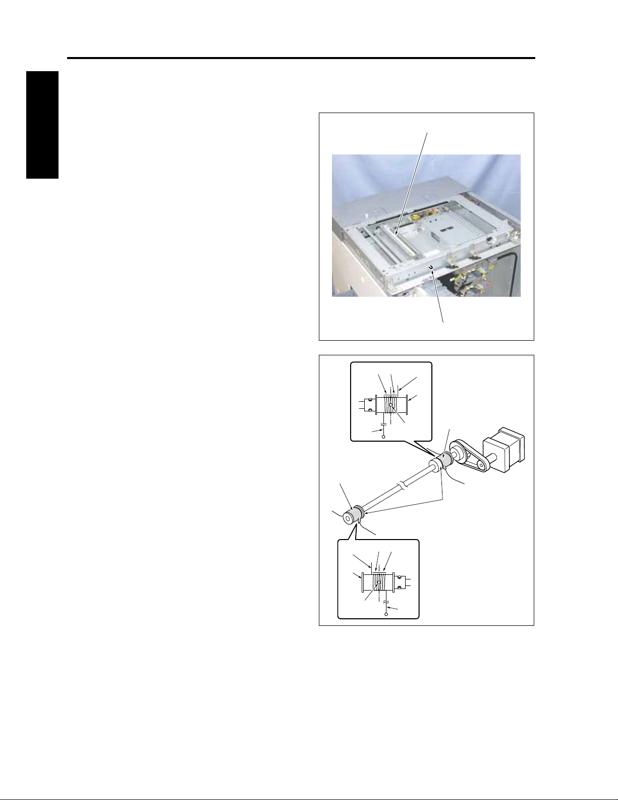
SCANNER CF5001 Field Service Ver.1.0 Sep 2003
2.7 Reinstalling the scanner wire
A. Procedure
1. Move the V-mirror unit [1] to the paper exit side,
and pass the optical positioning jig [2] through
the V-mirror unit [1] from the front side.
I DIS./ASSEMBLY
Note:
• Be careful not to damage the mirror with the
jig.
• When reinstalling the scanner wire, be sure to
fasten the V-mirror with the optical position-
ing jig.
[1]
2. Drop into the fitting hole of the drive pulley [4] a
metal bead [3] provided at the center of each of
the scanner wires /F [1] and /R [2], and starting
from this hole, wind the scanner wire 2.5 turns
[5] outwards and 3.5 turns [6] inwards.
Note:
• For the scanner wires /F and /R, common
wires are used.
• Be sure to wind each of scanner wires so that
the wire terminal is on the outside and the
metal bead [7] on the inside.
• Be sure to wind each of scanner wires so that
both ends of the wire come out under the
drive pulley.
• Be sure to wind each of the scanner wires
closely around the drive pully with no wire
running on another wire.
[8]
[2]
[4]
[3]
[7]
[6]
[5]
[5]
[6]
[7]
[3]
[1]
[4]
[2]
8050ma3025
[8]
[4]
8050ma3026
3. After winding the scanner wires /F and R/, be
sure to fasten each wire end with a tape [8] so
that it will not come off.
1-20
Page 51
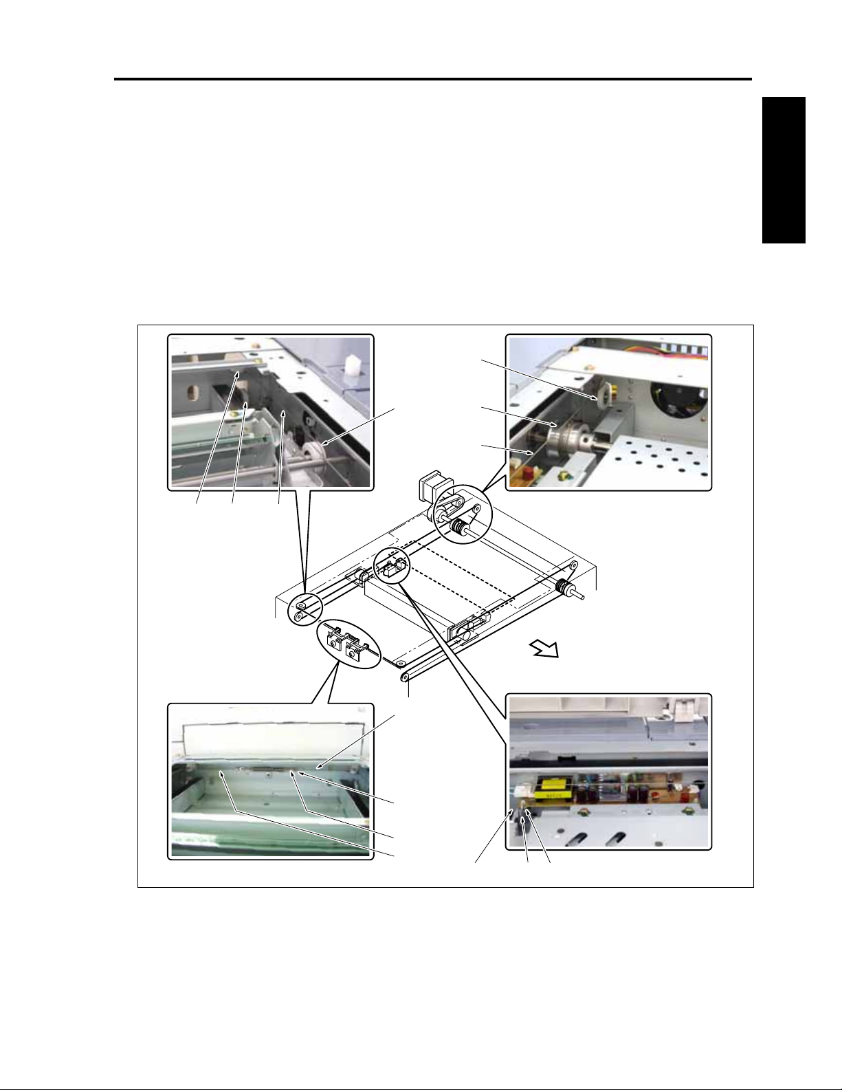
CF5001 Field Service Ver.1.0 Sep 2003 SCANNER
4. Pass the scanner wire /R [2] on the metal bead
[3] side (inside) which is wound around the drive
pulley [1] through the pulley /1 [4] and the V-mir-
ror pulley [5] in this order, and then hook the
metal bead [3] onto the wire stopper [6].
5. Pass the scanner wire /R [2] on the wire terminal
[7] side (outside) which is wound around the
drive pulley [1] through the pulley /2 [8] and the
outside of V-mirror pulley [5] and the pulley /3 [9]
in this order, and then hook the wire terminal [7]
onto the spring fixing plate [10].
[5]
6. Reinstall the scanner wire /F [11] by following
Steps 4 and 5.
I DIS./ASSEMBLY
[9]
[10]
[2]
[3][6][4]
FRONT
[2]
[3]
[1]
[11]
[2] [8][7]
8050ma3027
1-21
Page 52
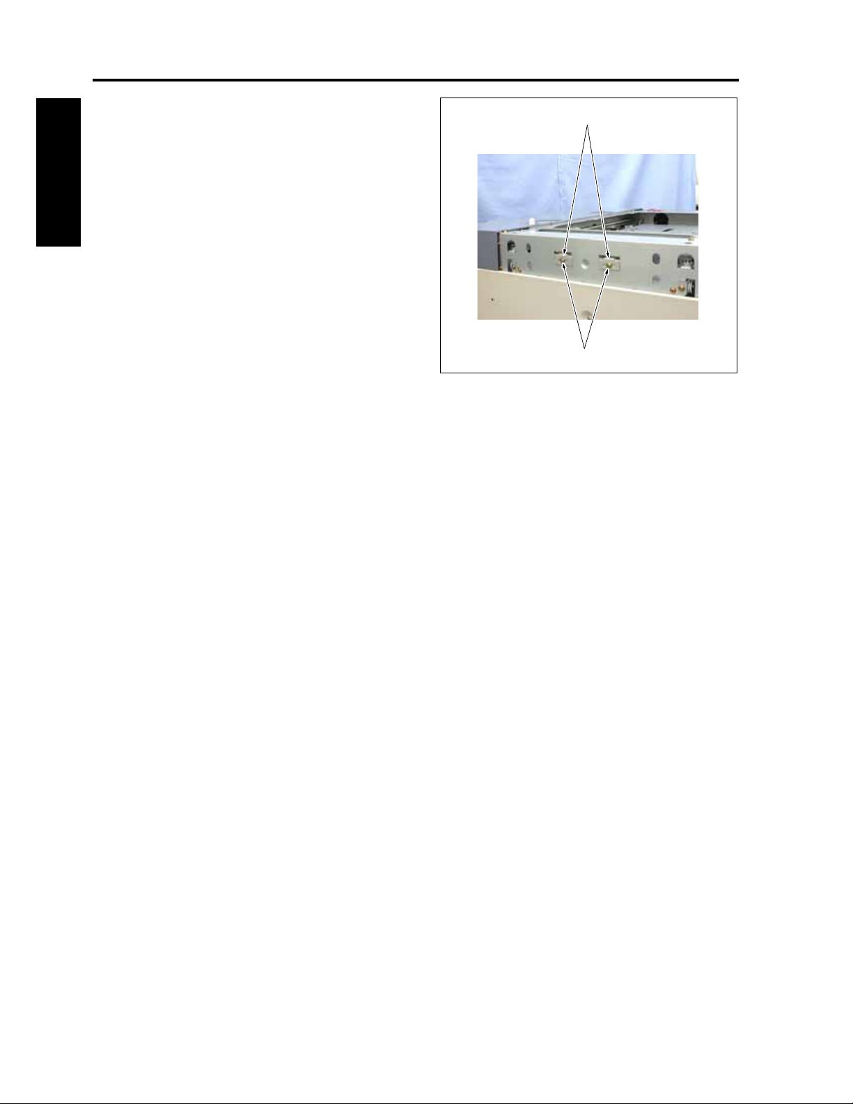
SCANNER CF5001 Field Service Ver.1.0 Sep 2003
7. Tighten the screws [1], one for each, and fasten
the 2 spring fixing plates [2].
[2]
8. For the subsequent steps, reinstall the parts fol-
lowing the removal steps in reverse.
I DIS./ASSEMBLY
[1]
8050ma3140
1-22
Page 53
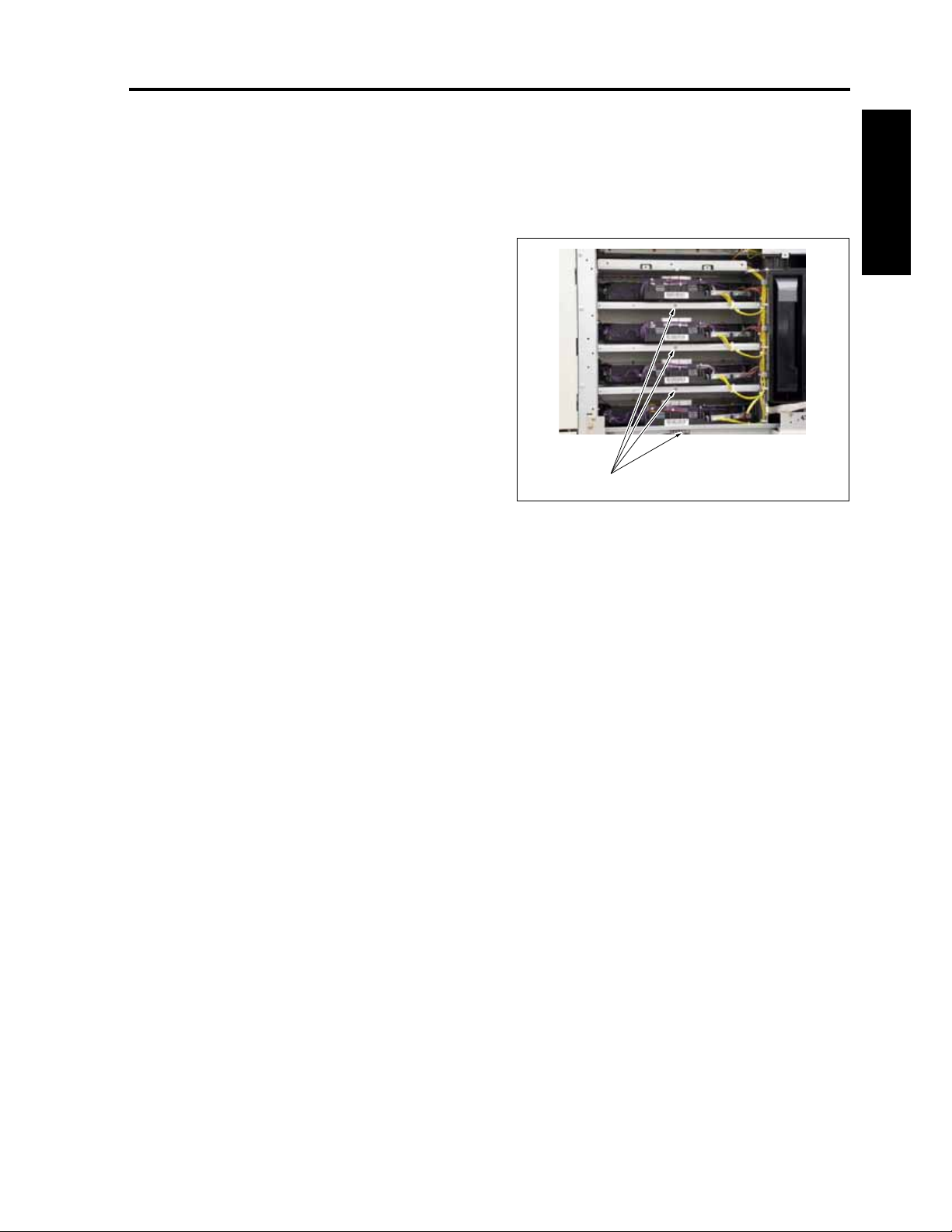
CF5001 Field Service Ver.1.0 Sep 2003 WRITING
3. WRITING
3.1 Screw that must not be removed
Note:
• The screws [1] of each unit of the YMCK are
not allowed to be removed. So, be careful not
to remove them.
I DIS./ASSEMBLY
[1]
8050ma3028
1-23
Page 54
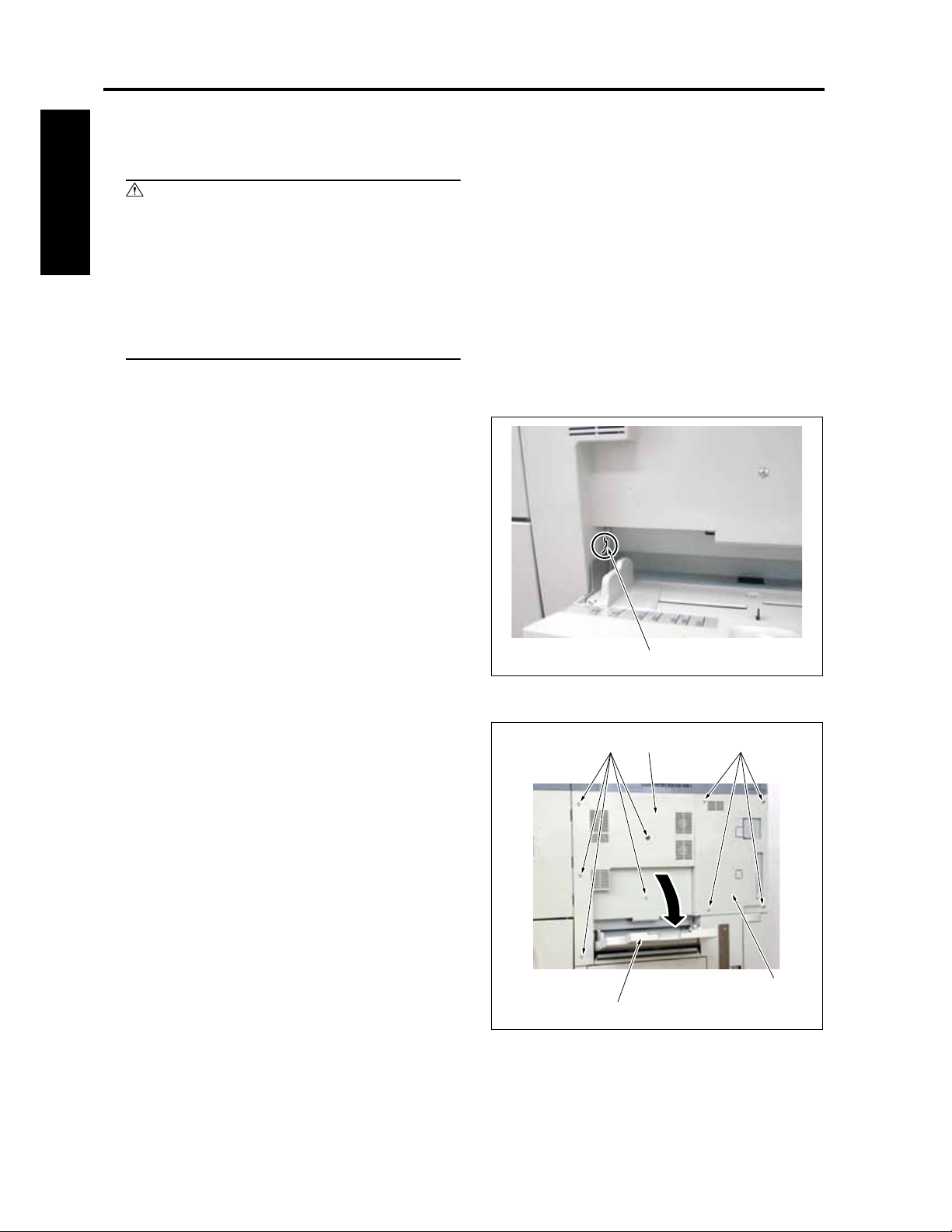
WRITING CF5001 Field Service Ver.1.0 Sep 2003
3.2 Removing and reinstalling the write unit
Warning:
• Be sure that the write unit should not be
I DIS./ASSEMBLY
powered with it slid from its normal instal-
lation position.
• Be sure not to remove the write unit cover
while being supplied with power. Otherwise,
laser beams get into your eyes and you may
lose your sight.
Note:
• Be sure not to remove the write unit cover. Do
not loosen the screws, either.
• When removing the write unit, be careful not
to touch the dust glass (to prevent the mirror
from being stained).
• Be sure not to remove the write unit for at
least two minutes after the main power switch
is turned off.
• When replacing the side cover /1, insert the
prong [1] on the side cover /1 into the notch
on the main body.
[1]
8050ma3175
A. Procedure
1. Open the by-pass tray [1].
2. Loosen 4 screws [2] and remove the side cover /
2 [3].
3. Loosen 5 screws [4] and remove the side cover /
1 [5].
[4] [2][5]
[1]
[3]
8050ma3029
1-24
Page 55
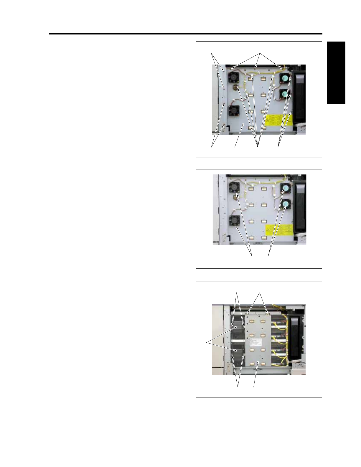
CF5001 Field Service Ver.1.0 Sep 2003 WRITING
4. Remove 5 relay connectors [1].
5. Remove 10 screws [2] and then remove the fan
[2] [2]
holder /R [3].
I DIS./ASSEMBLY
Note:
• Check the direction where the fan is assem-
bled.
[1] Turn the label side inside.
[2] Turn the label side outside.
6. Remove 2 screws [1] and then remove the write
pressing board [2] while pressing it downward.
7. Remove 2 screws [3] and then remove 2 write
cooling ducts [4].
Note:
• Be sure to hold the upper half of the write
pressing board when removing it.
[4]
[3]
[1]
[1]
[2]
[2][1][2] [3]
8050ma3030
5001ma3030
1-25
[2][3]
8050ma3031
Page 56
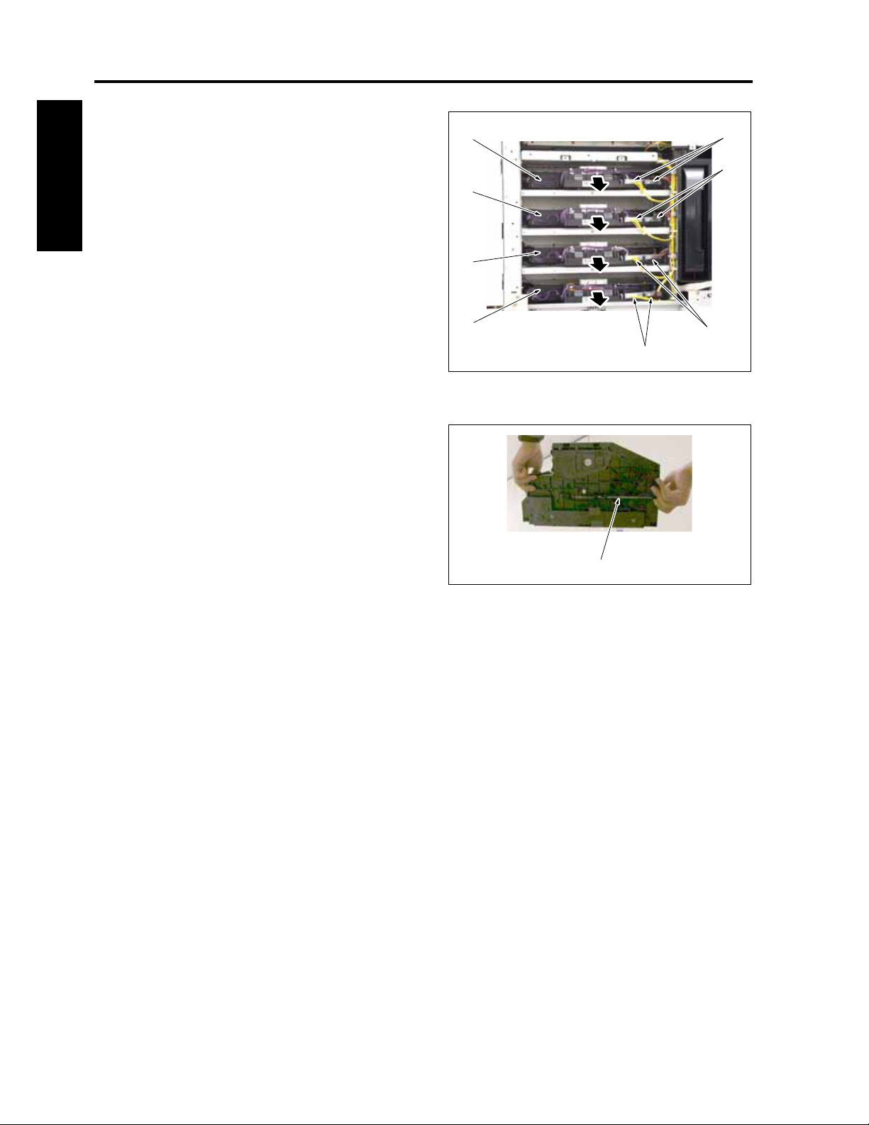
WRITING CF5001 Field Service Ver.1.0 Sep 2003
8. Remove the connectors [1], 2 each, and then
remove the write unit /Y [2], write unit /M [3],
write unit /C [4] and the write unit /K [5].
[2]
[1]
[1]
9. Reinstall the above parts following the removal
steps in reverse.
[3]
I DIS./ASSEMBLY
[4]
[5]
[1]
[1]
8050ma3032
Note:
• The write units /C, /M and /Y are all common.
• The bottom of the write units /C, /M and /Y is
provided with a wire tension spring [1] which
differentiates these three write units from the
write unit /K.
• Be careful not install any other write unit in
the installation place for the write unit /K.
[1]
8050ma3034
1-26
Page 57
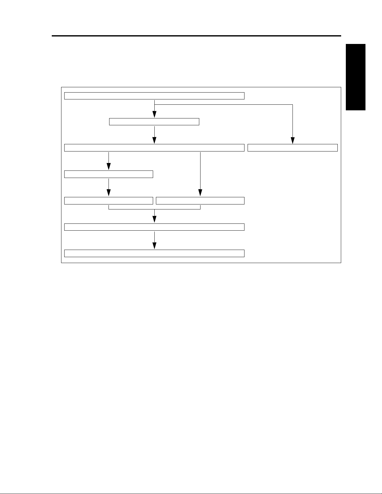
CF5001 Field Service Ver.1.0 Sep 2003 PROCESS UNIT
4. PROCESS UNIT
4.1 Flow of the disassembly of
the process unit section
Open the toner supply section
Open the front fan cover
Pull out the process unit Remove the charging corona unit
Pull out the transfer belt unit
Remove the drum cartridge Remove the developing unit
Remove the process unit
Remove the image correction unit
I DIS./ASSEMBLY
1-27
Page 58

PROCESS UNIT CF5001 Field Service Ver.1.0 Sep 2003
4.2 Cleaning the charging corona unit
A. Procedure
Note:
I DIS./ASSEMBLY
• The charging corona units are provided for
the four colors of yellow, magenta, cyan and
black. These units are common. Do not reuse
a charging corona unit that was once used for
a color since it has been stuck with the toner
of the color.
1. Open the toner supply section. (See "5.1 Open-
ing and closing the toner supply section.")
2. With the lever [2] of the charging corona unit [1]
pressed down once to the lower right side, pull
out the charging corona unit this side for
removal.
[1]
[2]
8050ma3037
1-28
Page 59

CF5001 Field Service Ver.1.0 Sep 2003 PROCESS UNIT
3. Remove a charging cleaning block [3] from the
charging suction assembly [2] provided on the
[3] [1]
outside of the toner supply unit [1].
Note:
• There are two charging cleaning blocks pro-
vided. Be sure to use either of these two
blocks when cleaning the charging corona.
I DIS./ASSEMBLY
4. Holding the charging corona unit [2] so that the
charging control plate [1] comes up, set the
charging cleaning block [3] to the notch and
insert it from under the bottom on the rear side,
and turn it about 45° clockwise.
Note:
• If the charging wire is cleaned with the charg-
ing control plate facing down, there is a risk
that dust that has stuck to the charging wire
sticks to the charging control plate. So, when
cleaning the charging wire, be sure to hold the
charging corona unit so that the charging
control plate comes upward.
5. Clean the charging wire [4] by sliding back and
forth the charging cleaning block [3].
6. Reinstall the above parts following the removal
steps in reverse.
[1]
[2]
[2]
[3]
8050ma3038
8050ma3039
1-29
Page 60

PROCESS UNIT CF5001 Field Service Ver.1.0 Sep 2003
4.3 Cleaning/replacing, removing and reinstalling
the charging wire assy
/the charging control plate
A. Periodically replaced parts/cycle
I DIS./ASSEMBLY
• Charging wire assy: Every 100,000 copies
• Charging control plate: Every 200,000 copies
• Charging grid spring: Every 200,000 copies
Note:
• The charging corona unit is made up of a
charging wire assy, charging control plate and
a charging grid spring.
B. Procedure
1. Remove the charging corona unit. (See "4.2
Cleaning and replacing the charging corona
unit.")
2. Remove 2 charging control springs [1] and then
remove the charging control plate [2].
3. Clean the charging control plate by blowing off
dust with a blower brush.
4. Reinstall the above parts following the removal
steps in reverse.
Note:
• Be sure to install the charging control plate so
that the side on which the charging control
spring is hooked comes to the front of the
charging corona unit.
• Be sure to install each of the charging control
springs with its tips [3] of both ends point
toward the charging wire.
[2]
[1]
[2]
1-30
[3]
8050ma3040
Page 61

CF5001 Field Service Ver.1.0 Sep 2003 PROCESS UNIT
4.4 Pulling out the process unit
Note:
• In order to prevent the main body from falling
down, the process unit and the ADU are pro-
vided with a safety mechanism so that they
cannot be pulled out at the same time.
• If the ADU has been pulled out when pulling
out the process unit, be sure to push it back
into the main body.
A. Procedure
1. Open the toner supply section. (See "5.1 Open-
ing and closing the toner supply section.")
2. Loosen the screw [1] and open the front fan
cover [2].
[2]
I DIS./ASSEMBLY
3. Bring down the stand handle /L [1] and the
stand handle /R [2] to the inside at the same
time to release the fixing of the process unit [3].
Then, hold each of the stand handles to pull out
the process unit [3].
4. Reinstall the above parts following the removal
steps in reverse.
1-31
[1]
[1]
8050ma3035
[3]
[2]
8050ma3036
Page 62

PROCESS UNIT CF5001 Field Service Ver.1.0 Sep 2003
4.5 Removing and reinstalling the transfer belt unit
A. Procedure
1. Pull out the process unit. (See "4.4 Pulling out
the process unit.")
I DIS./ASSEMBLY
2. Loosen the screws [1], 2 each.
3. After turning once the belt positioning shaft [2]
counterclockwise, pull it out for removal.
[2]
[1]
4. Remove the supporting rod [3] from the charg-
ing corona suction assembly [2] provided on the
inside of the toner supply unit [1].
Note:
• The supporting rod is an auxiliary device to
allow a removed transfer belt unit to self
stand. When removing the transfer belt unit,
be sure to make necessary arrangements in
advance.
[1]
[2]
8050ma3043
[3] [1]
8050ma3044
1-32
Page 63

CF5001 Field Service Ver.1.0 Sep 2003 PROCESS UNIT
5. With the handle [1] raised up, remove the trans-
fer belt unit [2].
[1]
[2]
Note:
• Be careful not to touch and damage the trans-
fer belt [3] with bare hands.
• Make sure to grab both ends of the handle of
the transfer belt with both hands.
[3]
Hold
Hold
[1]
I DIS./ASSEMBLY
6. Set the supporting rod [2] to the transfer belt unit
[1] to allow it to self stand.
7. Reinstall the above parts following the removal
steps in reverse.
Note:
• Make sure not to touch and damage the trans-
fer belt unit with the drum at installation.
[2]
5001ma3045
[1][2]
8050ma3046
1-33
Page 64
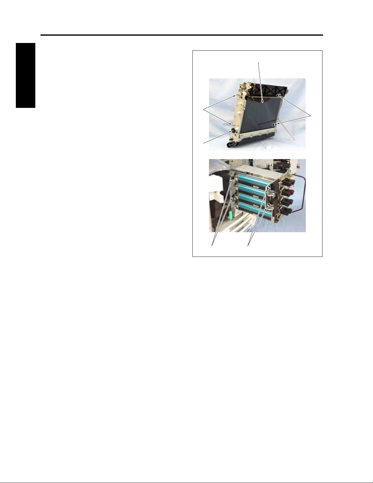
PROCESS UNIT CF5001 Field Service Ver.1.0 Sep 2003
Note:
• When reinstalling the transfer belt unit [1], be
sure to turn the cam [3] clockwise fully until it
[1]
will not turn any more before starting work.
• Be sure to install the transfer belt unit so that
2 transfer support blocks /F [4] and the 2
I DIS./ASSEMBLY
transfer support blocks /R [5] are accompa-
nied with the guide pins [2] provided at two
places each at front and rear.
[2]
• Be sure not to rotate the transfer belt when
the transfer belt unit self stand with a support-
ing rod.
[3]
[2]
[5]
[4]
8050ma3047
1-34
Page 65
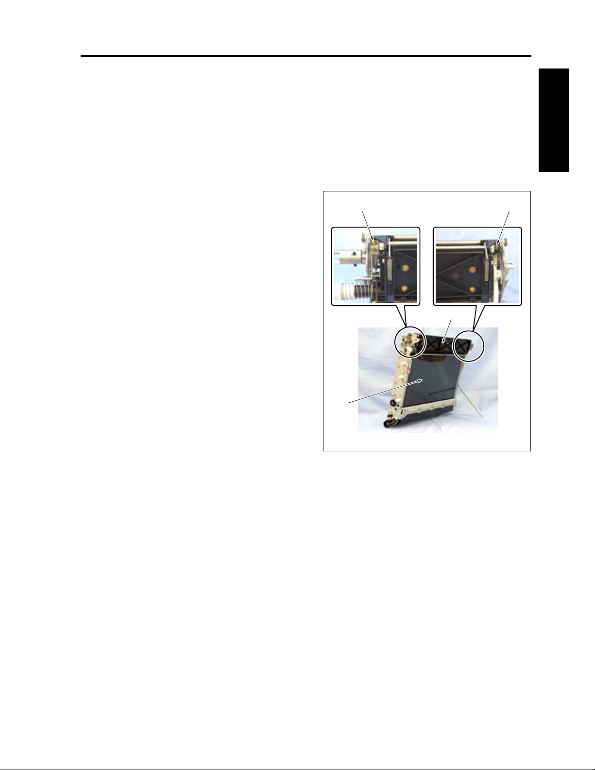
CF5001 Field Service Ver.1.0 Sep 2003 PROCESS UNIT
4.6 Replacing the belt cleaning brush unit
A. Periodically replaced parts/cycle
• Belt cleaning brush unit: Every 600,000 copies
B. Procedure
1. Remove the transfer belt unit. (See "4.5 Remov-
ing and reinstalling the transfer belt unit.")
2. Remove 2 screws [2] while holding the belt
cleaning unit [1] by hand, and then remove the
belt cleaning unit.
3. Replace the belt cleaning brush unit with a new
one.
4. Reinstall the above parts following the removal
steps in reverse.
Note:
• The belt cleaning unit is made up of the belt
cleaning brush unit and the parts listed below.
(For details of these parts, see "4.7 Replacing
the belt cleaning blade" and "4.8 Replacing
the toner collection sheet /1.")
Belt cleaning blade : 1 piece
Blade spring : 2 pieces
Stop ring : 2 pieces
Blade fulcrum shaft : 1 piece
Toner collection sheet /1 : 1 piece
Toner collection sheet /2 : 1 piece
Screw : 3 pieces
• Before installing the belt cleaning unit, apply
the setting powder on the portion [3] on the
transfer belt.
• When reinstalling it, set the guide sections
provided on both sides below the belt clean-
ing unit to the pins of the transfer belt unit,
and then attach the screws.
I DIS./ASSEMBLY
[2][2]
[1]
[3]
8050ma3048
1-35
Page 66
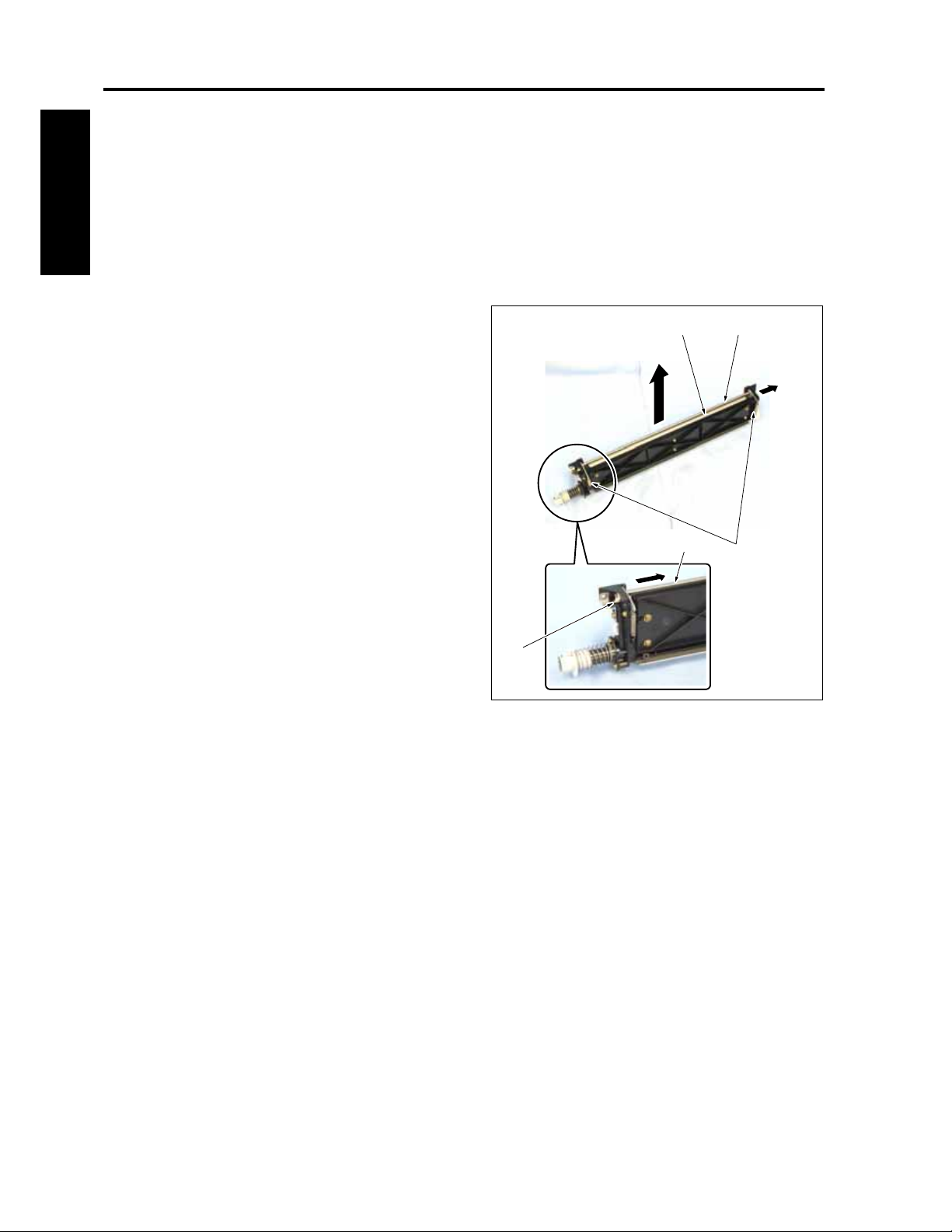
PROCESS UNIT CF5001 Field Service Ver.1.0 Sep 2003
4.7 Replacing the belt cleaning blade
A. Periodically replaced parts/cycle
• Belt cleaning blade: Every 100,000 copies
I DIS./ASSEMBLY
B. Procedure
1. Remove the belt cleaning unit. (See "4.6
Replacing the belt cleaning unit.")
2. Remove 2 blade springs [1].
3. After removing the stop ring [2], pull out the
blade support shaft [3] and remove the belt
cleaning blade [4].
4. Reinstall the above parts following the removal
steps in reverse.
Note:
• Before installing the belt cleaning unit, coat
the entire surface on the side on the transfer
belt, on which the belt cleaning unit is to be
mounted, with the setting powder.
[2]
[3]
[3][4]
[1]
8050ma3049
1-36
Page 67
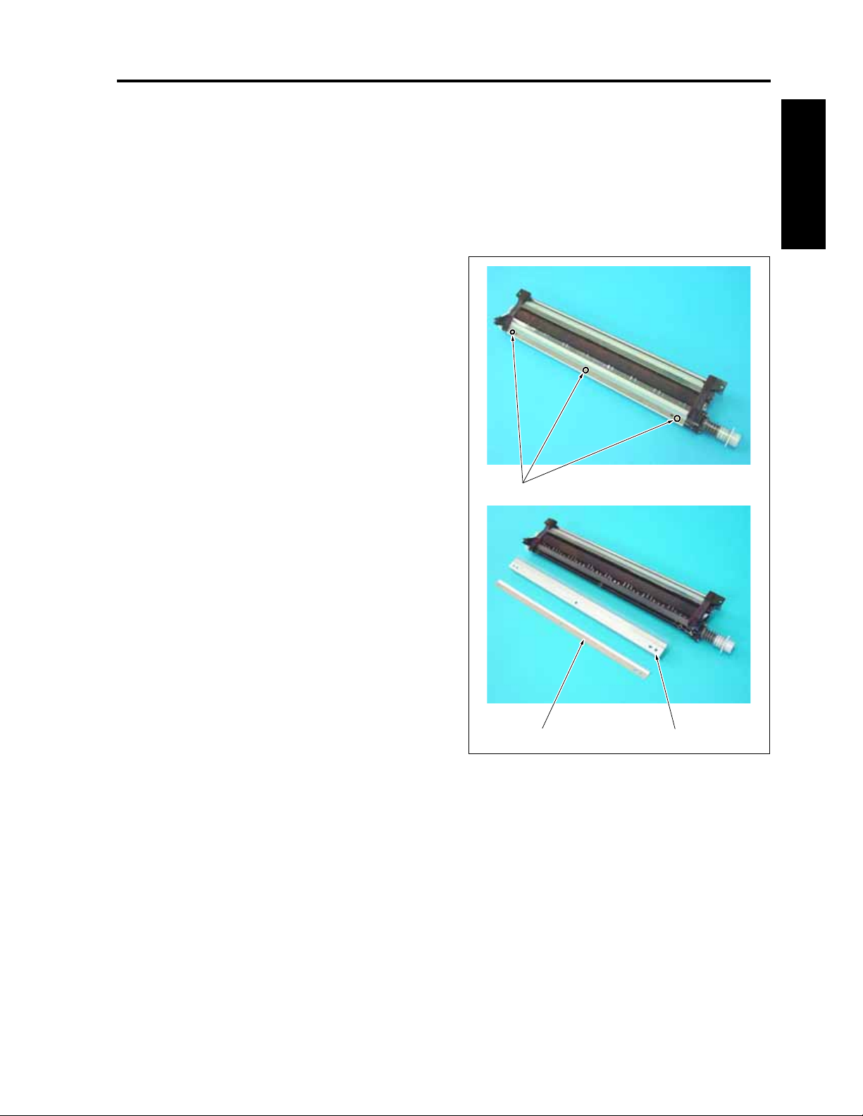
CF5001 Field Service Ver.1.0 Sep 2003 PROCESS UNIT
4.8 Replacing the toner collection sheet /1
A. Periodically replaced parts/cycle
• Toner collection sheet /1: Every 200,000 copies
B. Procedure
1. Remove the belt cleaning unit.
2. After removing 3 screws [1], remove the toner
collection sheet /2 [2] and then remove the toner
collection sheet /1 [3].
3. Reinstall the above parts following the removal
steps in reverse.
Note:
• Be careful not to fold the PET sheet of the
toner collection sheet /1, or damage it by hit-
ting it on the edge.
I DIS./ASSEMBLY
[1]
1-37
[3][2]
8050ma3159
Page 68
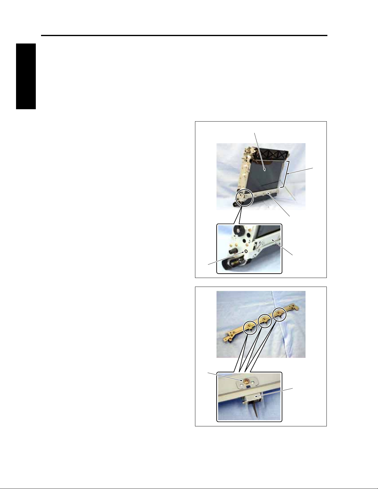
PROCESS UNIT CF5001 Field Service Ver.1.0 Sep 2003
4.9 Replacing the belt separation claw
A. Periodically replaced parts/cycle
• Belt separation claw: Every 600,000 copies
I DIS./ASSEMBLY
B. Procedure
1. Remove the transfer belt unit. (See "4.5 Remov-
ing and reinstalling the transfer belt unit.")
2. Remove the screw [1] and then remove the sep-
aration claw unit [2].
Note:
• Be careful not to touch and/or damage the
transfer belt [3] with bare hands.
• When reinstalling the separation claw unit, be
sure to apply setting powder to the semicircle
[4] of the transfer belt [3].
[1]
[3]
[4]
[2]
[2]
8050ma3050
3. Remove the screws [1], one each, and then
remove 3 transfer belt separation claws [2].
4. Reinstall the above parts following the removal
steps in reverse.
[1]
[2]
8050ma3051
1-38
Page 69
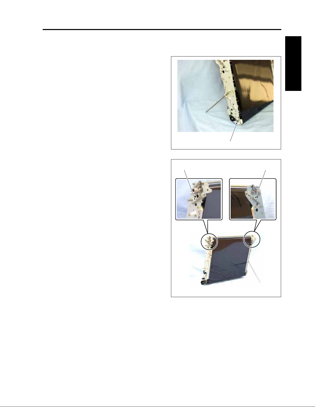
CF5001 Field Service Ver.1.0 Sep 2003 PROCESS UNIT
4.10 Replacing the transfer belt
A. Screw that must not be removed
Note:
• The screws [1] shown in the drawing below
are not allowed to be removed. Be careful not
to remove them.
B. Periodically replaced parts/cycle
• Transfer belt: Every 200,000 copies
[1]
C. Procedure
1. Remove the transfer belt unit. (See "4.5 Remov-
ing and reinstalling the transfer belt unit.")
2. Remove the belt cleaning unit. (See "4.6
Replacing the belt cleaning unit.")
3. Remove the separation claw unit. (See "4.9
Replacing the belt separation claw.")
4. Remove 2 tension springs [1].
8050ma3148
[1][1]
I DIS./ASSEMBLY
1-39
8050ma3053
Page 70
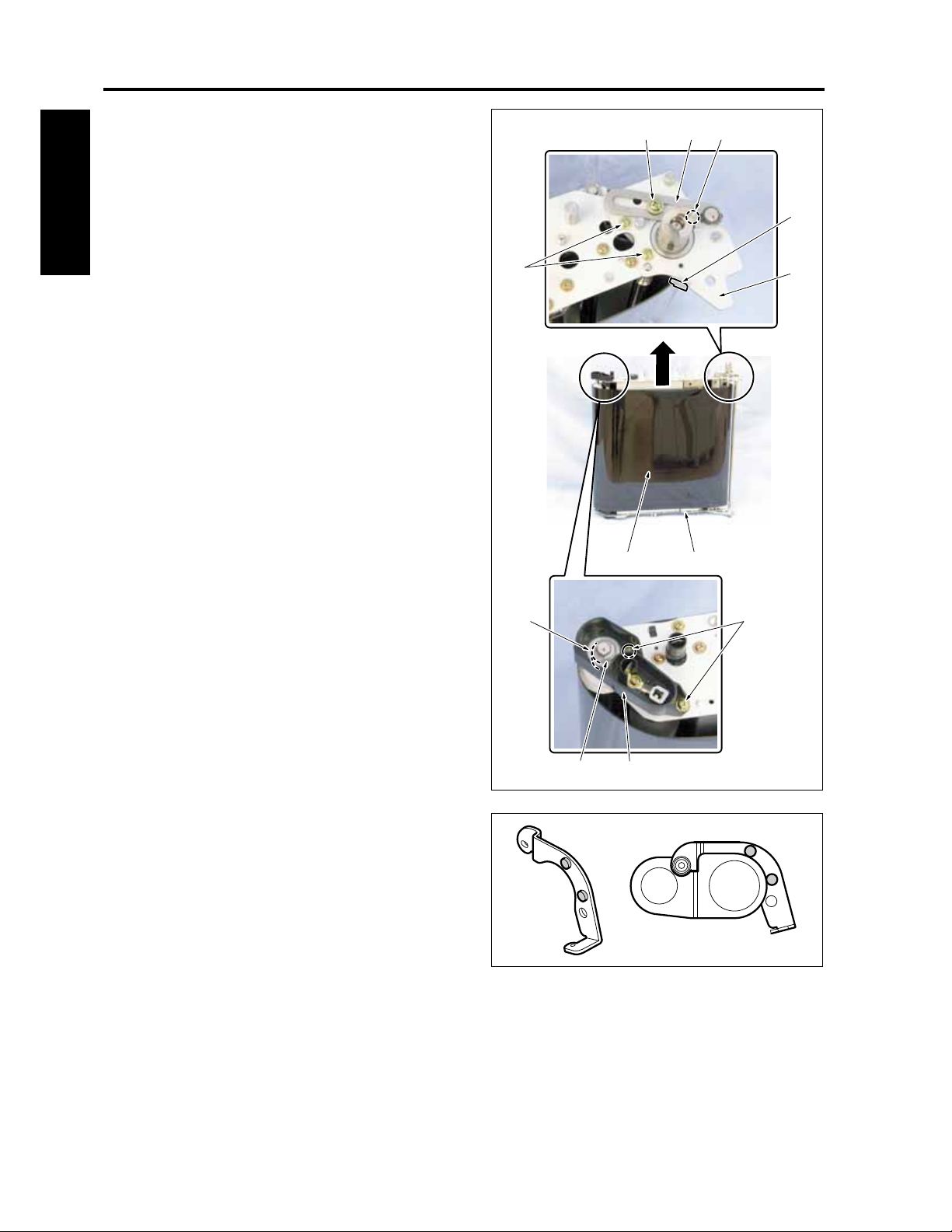
PROCESS UNIT CF5001 Field Service Ver.1.0 Sep 2003
5. Stand up the transfer belt unit [1] by using the
front side of the transfer belt unit [1] as the bot-
[3] [6][2]
tom.
6. Remove the screw [2] and release the fixing of
the handle [3].
7. Remove 2 screws [4] and then remove the shaft
I DIS./ASSEMBLY
stopper [5].
8. Remove the screw [6] and then remove the ten-
[4]
sion plate /R [7].
Note:
• When reinstalling the tension plate /R, knock
against the projection of the tension plate /R.
9. Remove 2 screws [8] and then remove the high
voltage supply curler /R [9].
10. Remove the stop ring [10] and then remove the
bearing [11].
[12] [1]
[7]
[5]
Note:
• When reinstalling the stop ring, be sure to
raise the shaft so that the stop ring is set in
the groove of the shaft.
11. Pull up the transfer belt [12] for removal.
Note:
• Be sure to reinstall the transfer belt so that
the rear side stamped with "UP SIDE" at the
edge of the belt comes up.
• When holding the transfer belt by hand, hold it
within 10mm from the upper end. Be careful
not touch any part other than this.
12. Reinstall the above parts following the removal
steps in reverse.
Note:
• Be careful not to touch and/or damage the
transfer belt with bare hands.
• Before installing the belt cleaning unit, coat
the entire surface on the side on the transfer
belt, on which the belt cleaning unit is to be
mounted, with the setting powder.
[11]
[8]
[9][10]
8050ma3054
8050ma3152
1-40
Page 71
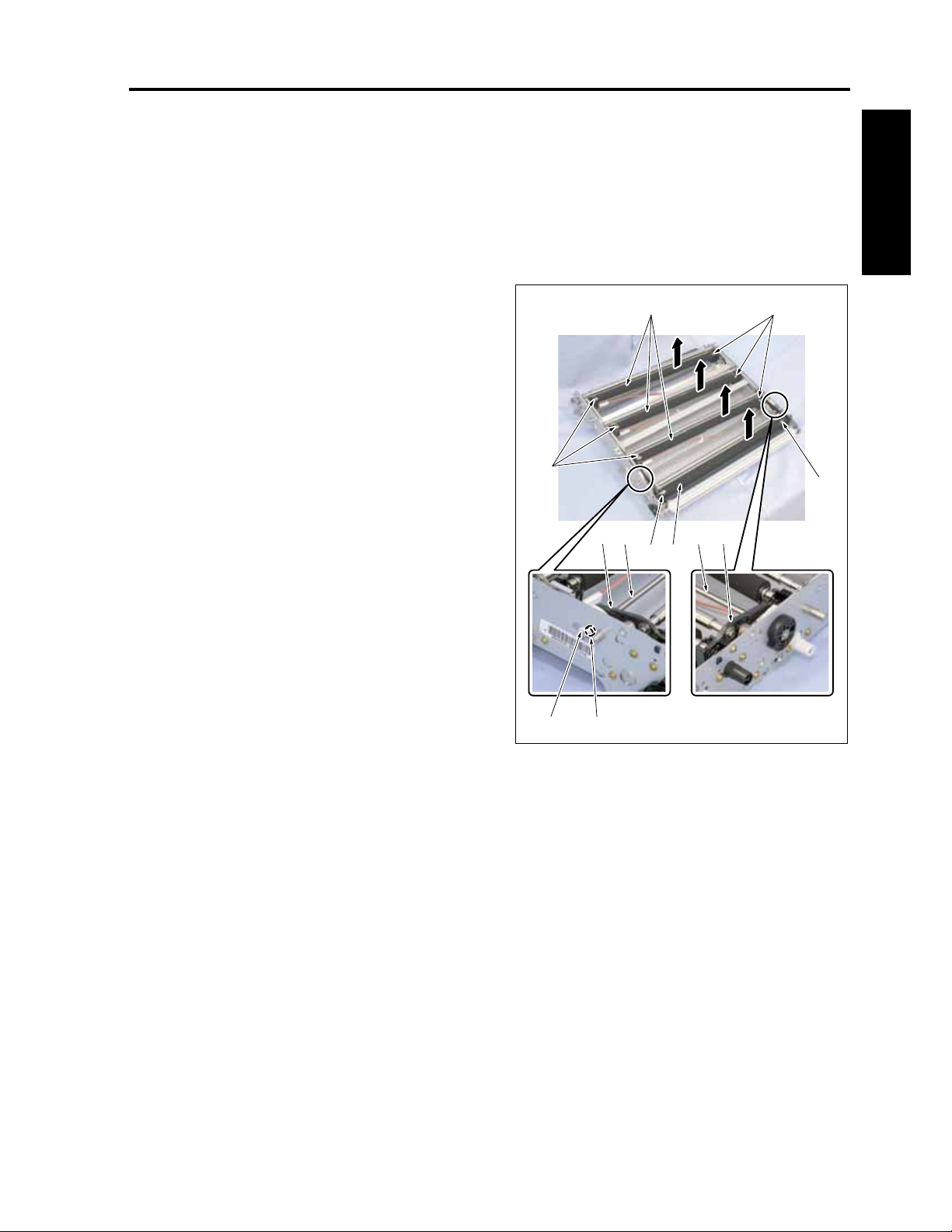
CF5001 Field Service Ver.1.0 Sep 2003 PROCESS UNIT
4.11 Replacing the 1st transfer roller
A. Periodically replaced parts/cycle
• 1st transfer roller /Y, /M, /C, /K: Every 200,000
copies
B. Procedure
1. Remove the transfer belt. (See "4.10 Replacing
the transfer belt.")
2. Place the transfer belt unit as shown in the illus-
tration.
3. Remove the stop ring [1].
4. After removing 1 bearing [2], slide the stopper /4
[3] to open the tip end of the transfer release
arm [4].
5. Remove the 1st transfer roller /K [6] while sliding
it.
6. Remove 3 1st transfer rollers/Y, /M, /C [5].
Note:
• Be sure to reinstall the 1st transfer roller so
that a shallow groove near the groove of the
E-ring comes this side.
[7]
[4] [3]
[3] [4]
[7] [6]
[7][5]
[7]
I DIS./ASSEMBLY
7. Remove the E-rings [7], 2 each, from each of
the 1st transfer rollers.
8. Reinstall the above parts following the removal
steps in reverse.
[2][1]
8050ma3055
1-41
Page 72
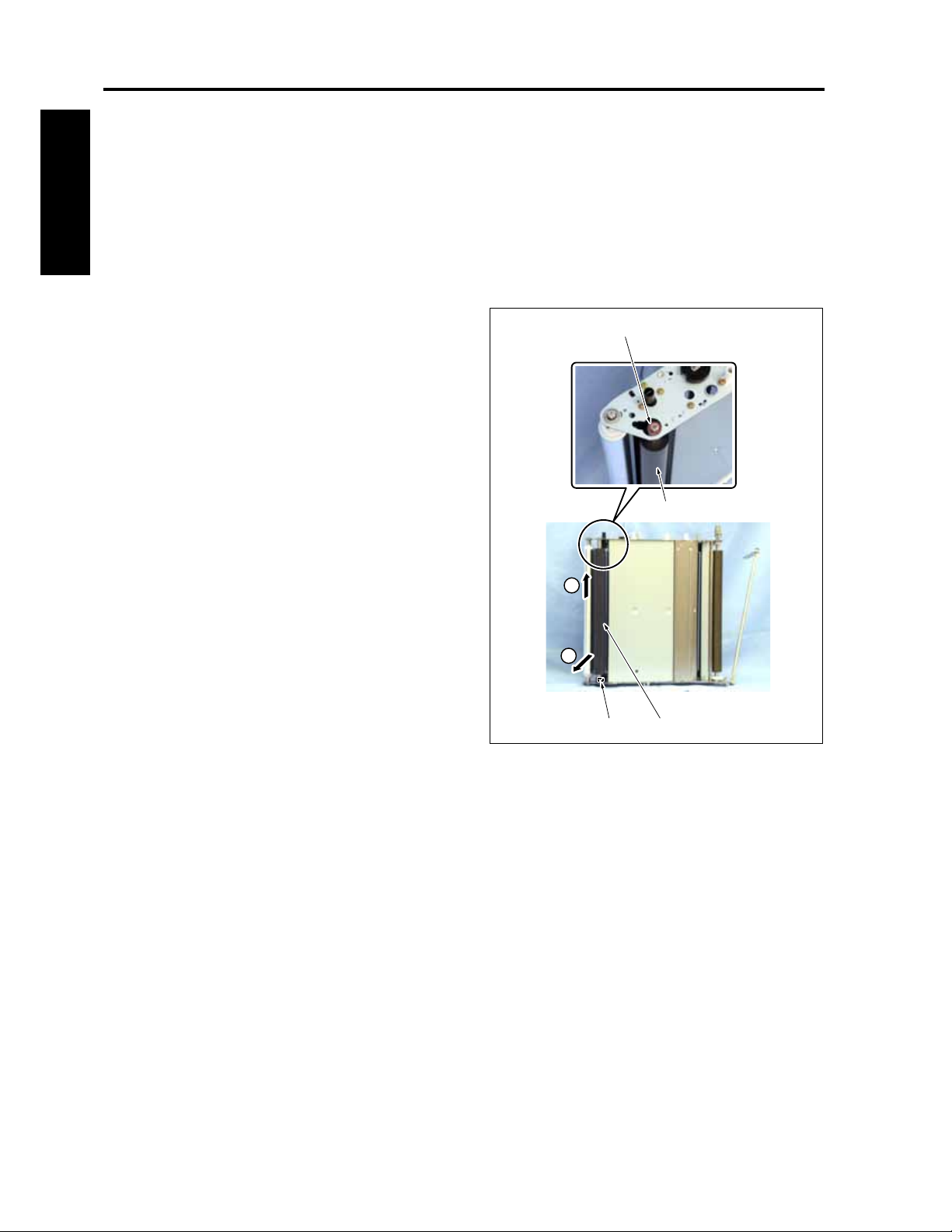
PROCESS UNIT CF5001 Field Service Ver.1.0 Sep 2003
4.12 Replacing the 2nd transfer roller /U
A. Periodically replaced parts/cycle
• 2nd transfer roller /U: Every 200,000 copies
I DIS./ASSEMBLY
B. Procedure
1. Remove the transfer belt. (See "4.10 Replacing
the transfer belt.")
2. After raising the 2nd transfer roller /U [1] once,
remove it diagonally from the lower side.
Note:
• The fixing of the 2nd transfer roller /U was
released when the transfer belt was removed
at the time of the removal of the high voltage
supply curler.
• Be sure to reinstall the 2nd transfer roller /U
so that the shaft end with a dent comes to the
bottom.
3. Remove 2 bearings [2] from the 2nd transfer
roller /U [1].
4. Reinstall the above parts following the removal
steps in reverse.
[2]
[1]
1
2
1-42
[1][2]
8050ma3056
Page 73
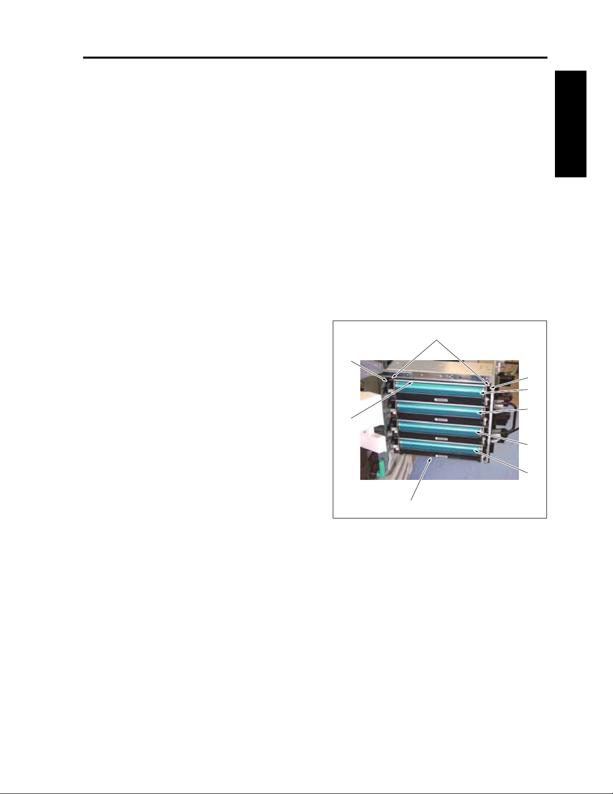
CF5001 Field Service Ver.1.0 Sep 2003 PROCESS UNIT
4.13 Replacing the drum cartridge
A. Periodically replaced parts/cycle
• Drum cartridge: Every 100,000 copies
B. Procedure
Note:
• The drum cartridges are provided for the four
colors of yellow, magenta, cyan and black,
and they are all common. However, be sure to
avoid reusing a drum cartridge that was once
used for a color since it has been stuck with
the toner of that color.
1. Remove the transfer belt unit. (See "4.5 Remov-
ing and reinstalling the transfer belt unit.")
2. After raising once both ends [2] of the drum stay
/U [1], hold them and remove the drum cartridge
/Y [3].
3. Remove the drum cartridge /M [4], drum car-
tridge /C [5] and the drum cartridge /K [6] in the
same manner as in Step 2.
4. Reinstall the above parts following the removal
steps in reverse.
Note:
• When reinstalling each drum cartridge, be
sure to check if both ends of the cartridge
have been dropped into the grooves of the
drum installation blocks /F [7] and /R [8]. (The
drum installation blocks /F [7] and /R [8] are
for yellow drum cartridges. Repeat the steps
for other cartridges in the same manner.)
• When reinstalling the drum cartridge /K [6], be
careful that the mylar [9] is not caught up.
• Be careful not touch and damage the photo-
sensitive material of the drum with bare
hands.
• When the drum cartridge is not used for a
long period of time, be sure to store it in the
dark place with a cover on it (to shield the
light).
[8]
[1]
[9]
I DIS./ASSEMBLY
[2]
[7]
[3]
[4]
[5]
[6]
8050ma3057
1-43
Page 74

PROCESS UNIT CF5001 Field Service Ver.1.0 Sep 2003
4.14 Removing and reinstalling the drum
A. Screw that must not be removed
Note:
I DIS./ASSEMBLY
• Screws that are paint locked are not allowed
to be removed. Be careful not to remove them
at all costs.
[1]
[1]
B. Procedure
1. Remove the drum cartridge. (See "4.13 Replac-
ing the drum cartridge.")
2. Remove 2 screws [1] and then remove the drum
stay /U [2].
[1]
[2]
8050ma3058
8050ma3059
1-44
Page 75

CF5001 Field Service Ver.1.0 Sep 2003 PROCESS UNIT
3. Remove the coupling shaft /A [1] and then
remove the coupling /A [2].
4. Remove 2 screws [3].
5. Remove the position adjusting plate /R [8].
[6]
6. Remove the stop ring [4] and then remove the
screw idler gear [5].
7. Remove 3 screws [6] (be careful not to remove
black screw.).
8. Remove the position adjusting plate /F [7].
9. Hold both ends of the drum [9] and raise it up for
removal.
[7] [5] [4][9]
Note:
• Be sure to reinstall the drum so that the cou-
pling side of the drum flange comes to the
rear side of the drum cartridge.
10. Reinstall the above parts following the removal
steps in reverse.
I DIS./ASSEMBLY
[3]
[1] [8][2]
8050ma3060
1-45
Page 76

PROCESS UNIT CF5001 Field Service Ver.1.0 Sep 2003
4.15 Replacing the developing unit
A. Periodically replaced parts/cycle
• Developing unit: Every 600,000 copies
I DIS./ASSEMBLY
B. Procedure
Note:
• Be careful not to fold the Teflon sheet posted
at the developing sleeve side of the develop-
ing unit upper cover.
• When cleaning the developing unit, be sure to
use Hydro-Wipe which is specified as a CE
tool. Using paper or cloth other than Hydro-
Wipe will cause the developing regulation
plate in the developing unit to be stuck with
dust and lint of the paper or cloth, thus result-
ing in white streaks on the images.
• The developing units are provided for the four
colors of yellow, magenta, cyan and black,
and they are all common. However, be sure to
avoid reusing a developing unit that was once
used for a color since it has been stuck with
the toner of that color.
1. Open the toner supply section. (See "5.1 Open-
ing and closing the toner supply section.")
2. Remove 2 screws [1] and then remove 4 devel-
oping support legs [3] provided inside the toner
supply unit [2].
Note:
• When placing the developing unit by itself, be
sure to set the developing support legs to the
body of the developing unit as a seat to pre-
vent the toner bristles section from getting in
touch with other sections.
3. Pull out the process unit. (See "4.4 Pulling out
the process unit.")
[2]
[3]
[3]
[1]
8050ma3062
1-46
Page 77

CF5001 Field Service Ver.1.0 Sep 2003 PROCESS UNIT
4. Remove the screws [1], 3 each, and then
remove 2 developing pressing blocks [2] while
[1] [1]
sliding the upper side of the developing pressing
blocks.
I DIS./ASSEMBLY
5. Remove the relay connectors [1], 1 each, and
then remove 4 developing units [2] one at a time.
6. Reinstall the above parts following the removal
steps in reverse. Place an appropriate color
label supplied with the developing unit on the
new unit.
Note:
• Be careful not to open the developing unit
cover.
[1]
[2]
[2]
8050ma3063
8050ma3064
1-47
Page 78

PROCESS UNIT CF5001 Field Service Ver.1.0 Sep 2003
4.16 Replacing the developer
A. Periodically replaced parts/cycle
• Developer: Every 100,000 copies
B. Procedure
I DIS./ASSEMBLY
1. Remove the developing unit. (See "4.15 Replac-
ing the developing unit.")
2. Put the developing unit [1] on end and rotate its
upper end in drawing an arc to discharge devel-
oper. After discharging the developer, repeat
Steps 3 and 4 below to discharge all of the
developer.
8050ma3149
3. Install the rotating jig [1] provided inside the
toner supply unit to the coupling [2] on the agita-
tor screw side and turn it in the arrow-marked
direction.
[1] [2]
8050ma3150
1-48
Page 79

CF5001 Field Service Ver.1.0 Sep 2003 PROCESS UNIT
4. Install the rotating jig to the coupling [1] on the
developing sleeve side and turn it in the arrow-
[1]
marked direction.
Note:
• If the jig is turned in the reverse direction, it
sometimes occurs that the developer is not
discharged completely. Be careful not to turn
it in the reverse direction.
5. Charge a new developer. (See "7. 36 mode," "II .
Adjustment" in Field Service.)
8050ma3151
I DIS./ASSEMBLY
1-49
Page 80
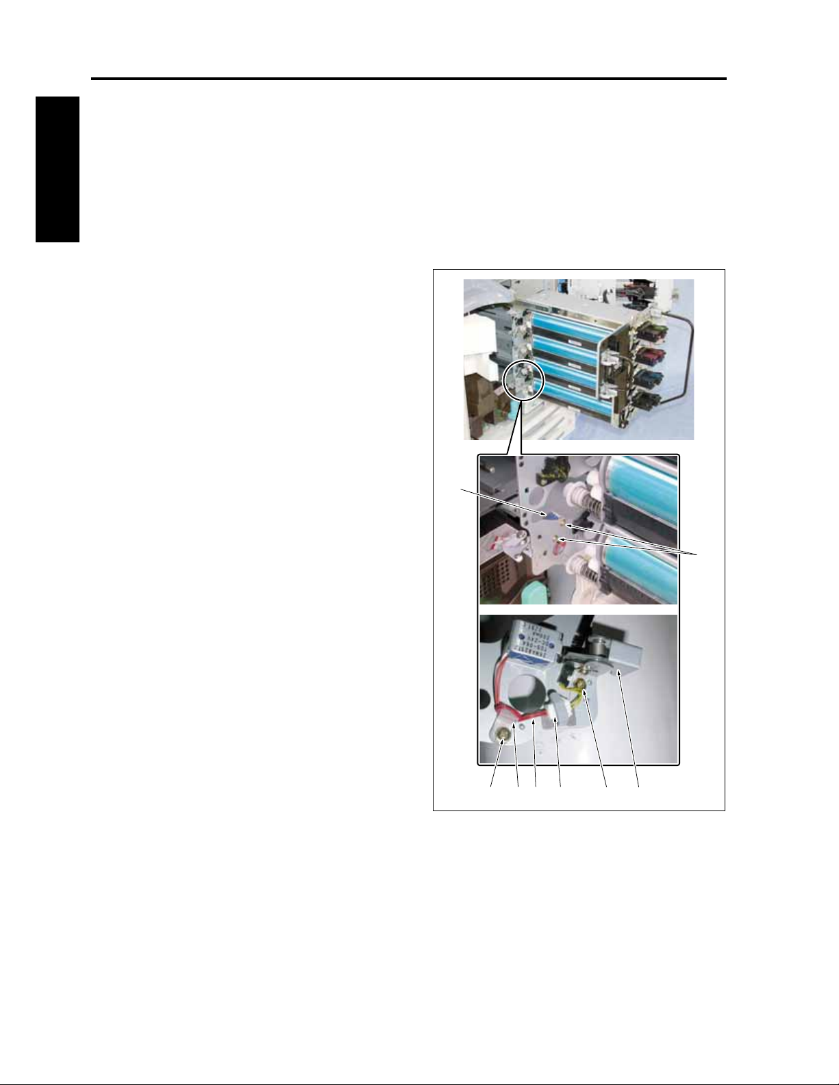
PROCESS UNIT CF5001 Field Service Ver.1.0 Sep 2003
4.17 Replacing the belt separation claw solenoid
A. Periodically replaced parts/cycle
• Developer: Every 1,500,000 copies
I DIS./ASSEMBLY
B. Procedure
1. Remove the transfer belt unit. (See "4.5 Remov-
ing and reinstalling the transfer belt unit.")
2. Remove the screw [1] and then remove the sole-
noid lever [2].
3. Remove the relay connector [3].
4. Remove the screw [4] and release the cable [6]
from the cable clamp [5].
5. Remove 2 screws [7] and then remove the SD1
(belt separation claw solenoid) [8].
6. Reinstall the above parts following the removal
steps in reverse.
Note:
• When having reinstalled the solenoid bar,
check to see if the shaft [9] of SD1 (belt sepa-
ration claw solenoid) moves smoothly while
sliding it.
[8]
[7]
1-50
[4] [5] [6] [3] [2] [1]
8050ma3069
Page 81
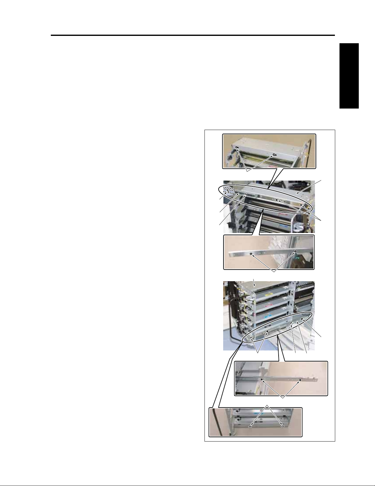
CF5001 Field Service Ver.1.0 Sep 2003 PROCESS UNIT
4.18 Removing and reinstalling the process unit
A. Procedure
1. Remove the transfer belt unit. (See "4.5 Remov-
ing and reinstalling the transfer belt unit.")
2. Remove all of the drum cartridges. (See "4.13
Replacing the drum cartridge.")
3. Remove all of the developing units. (See "4.15
Replacing the developing unit.")
4. Remove the screws [1], 2 each.
Note:
• When removing the process unit, be sure to
remove in advance the transfer belt unit, drum
cartridge and the developing unit.
• Be careful not to remove black screws.
[8]
[6]
I DIS./ASSEMBLY
5. Push back the process unit [6] until it becomes
possible to see the screw [5] through each hole
[4] of the guide rails /L [2] and /R [3].
6. Remove the screws [5], 1 each.
Note:
• Be careful not to remove black screws.
7. Pull out the process unit [6] again. Then remove
it from the guide rails /L [2] and /R [3] as
explained below:
The projection [7] on the guide rail /L is set into
the notch [8] of the process unit. The notch [10]
of the process unit is placed on the projection [9]
on the guide rail /R. Accordingly, slide the guide
rail /L a little against the process unit to remove
it from the guide rail /L, and then remove it from
the guide rail /R by raising the process unit.
8. Reinstall the above parts following the removal
steps in reverse.
[4]
[2]
[5]
[1]
[1]
[7][6]
[4]
[5]
[3]
1-51
[10] [9]
8050ma3070
Page 82
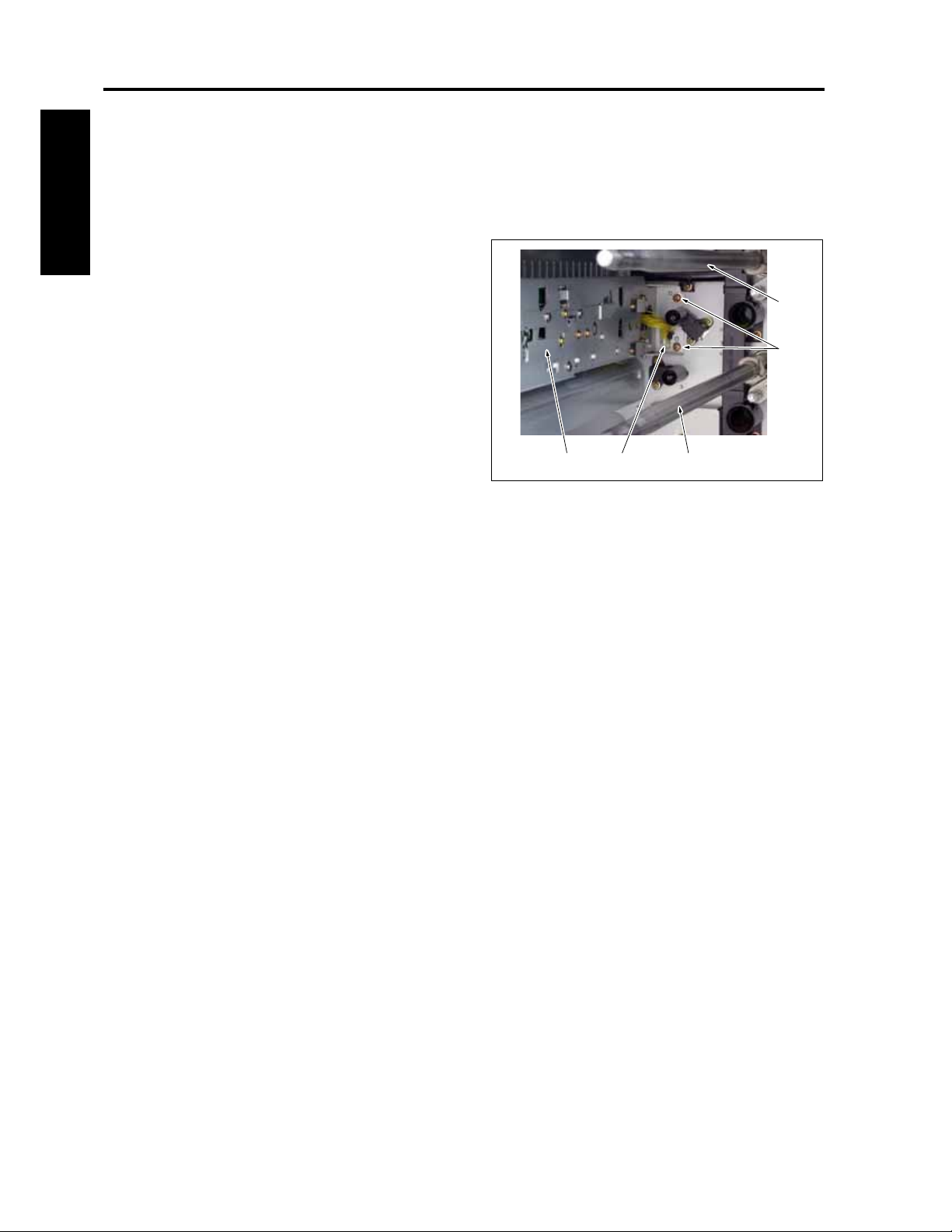
PROCESS UNIT CF5001 Field Service Ver.1.0 Sep 2003
4.19 Removing and reinstalling the image correction unit
A. Procedure
1. Remove the process unit. (See "4.18 Removing
and reinstalling the process unit.")
I DIS./ASSEMBLY
2. Remove a relay connector [1].
3. Remove 2 screws and then remove the image
correction unit [3].
4. Reinstall the above parts following the removal
steps in reverse.
Note:
• When removing the image correction unit, be
sure to remove in advance the process unit.
• When removing the image correction unit, be
careful not to touch the drum drive shaft [4] of
each color. Otherwise, this may cause stress
to it.
[4][3] [1]
8050ma3071
[4]
[2]
1-52
Page 83
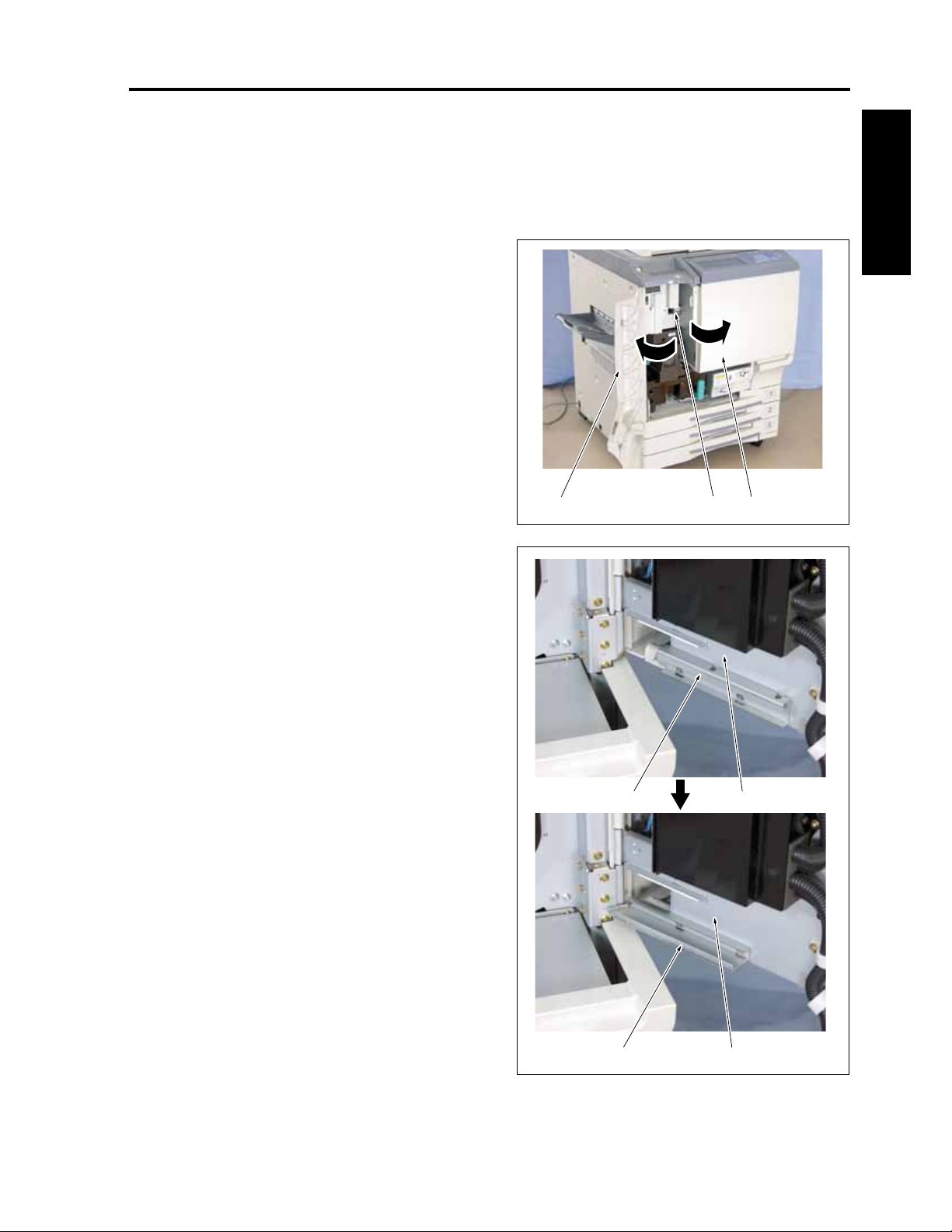
CF5001 Field Service Ver.1.0 Sep 2003 TONER SUPPLY
5. TONER SUPPLY
5.1 Opening and closing the toner supply section
A. Procedure
1. Open the front door [1].
2. Loosen the screw [2] and open the toner supply
section [3].
Note:
• With the toner supply section left open, be
sure not to apply force to the toner supply
sections such as the operation board. If
applied, the hinge of the toner supply section
may be deformed.
• When closing the toner supply section,
tighten the screw with a hand before using a
driver to prevent stripping the thread.
[1] [2] [3]
8050ma3072
I DIS./ASSEMBLY
3. Remove once the door lock [2] provided on the
inside of the toner supply section [1] and replace
it at a new position where it becomes a stopper.
4. Close the front door following the steps for
opening in reverse order.
Note:
• When the toner supply section is opened, be
sure to replace the door lock to a new position
where it becomes a stopper and prevent it
from getting in touch with the process unit
when being pulled out.
[2]
[1]
1-53
[2]
[1]
8050ma3073
Page 84
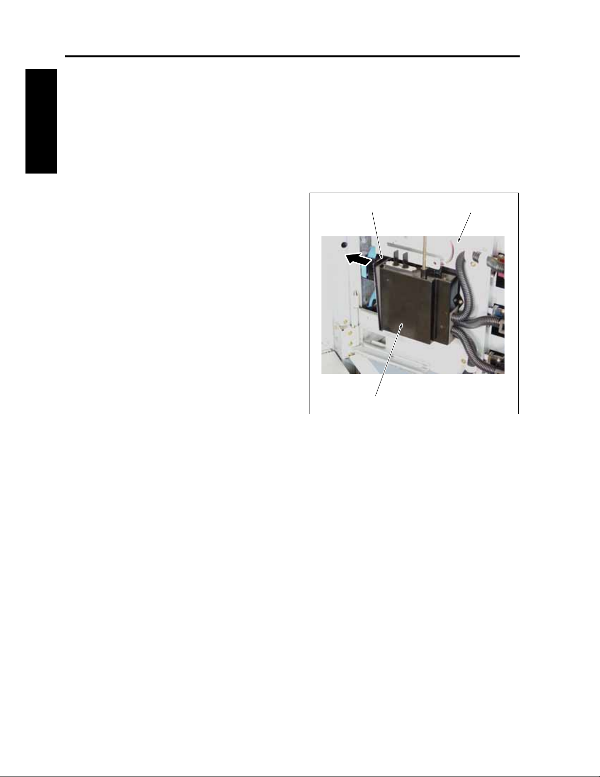
TONER SUPPLY CF5001 Field Service Ver.1.0 Sep 2003
5.2 Replacing the charging dust filter
A. Periodically replaced parts/cycle
• Charging dust filter: Every 600,000 copies
I DIS./ASSEMBLY
B. Procedure
1. Open the toner supply section. (See "5.1 Open-
ing and closing the toner supply section.")
2. Remove the charging dust filter [3] from the
charging suction assembly [2] provided on the
inside of the toner supply section [1].
3. Reinstall the above parts following the removal
steps in reverse.
[3] [1]
[2]
8050ma3074
1-54
Page 85
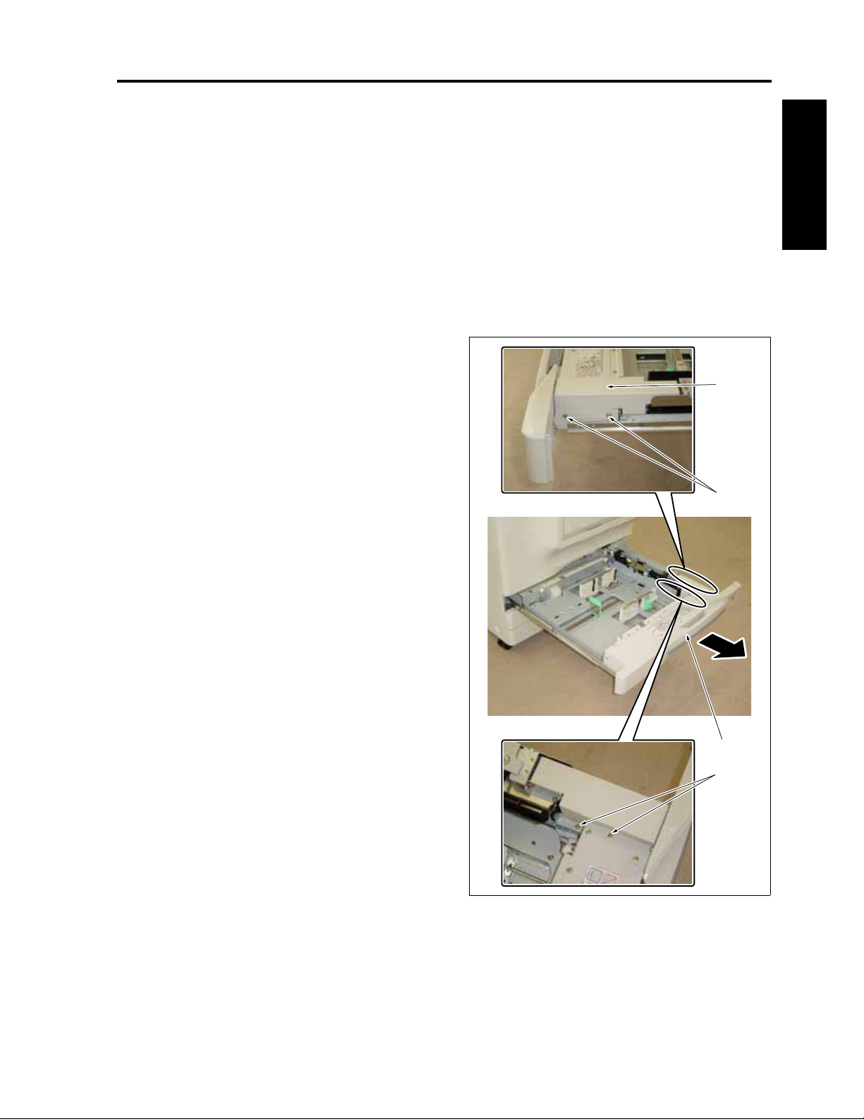
CF5001 Field Service Ver.1.0 Sep 2003 PAPER FEED TRAYS /1 to /3
6. PAPER FEED TRAYS /1 to /3
6.1 Removing and reinstalling the paper feed unit
A. Procedure
Note:
• Since the composition of the paper feed trays
/1 to /3 is the same, the explanation here is
made of the steps for the paper feed tray /1.
1. Pull out the paper feed tray /1 [1].
2. Remove 4 screws [2] and then remove the
paper feed unit cover [3].
[3]
I DIS./ASSEMBLY
[2]
[1]
[2]
8050ma3160
1-55
Page 86
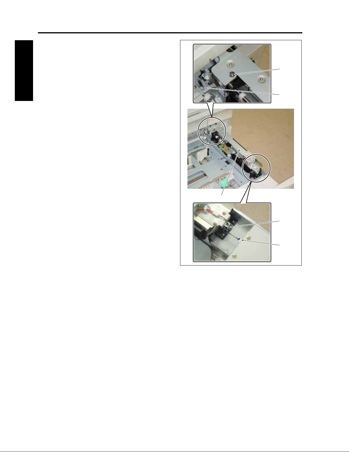
PAPER FEED TRAYS /1 to /3 CF5001 Field Service Ver.1.0 Sep 2003
3. Remove the connector [1].
4. Remove a screw [2] and loosen a hold-down
shaft screw [3].
5. After sliding the paper feed unit [4] to the rear
side, lift it up. Remove the connector [5] and
then remove the paper feed unit [4].
I DIS./ASSEMBLY
6. Reinstall the above parts following the removal
steps in reverse.
[3]
[5]
[4]
[2]
[1]
8050ma3161
1-56
Page 87
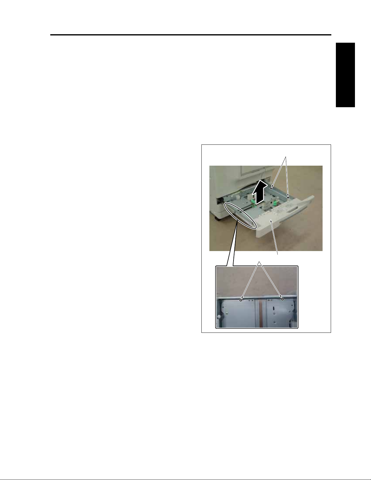
CF5001 Field Service Ver.1.0 Sep 2003 PAPER FEED TRAYS /1 to /3
6.2 Removing and reinstalling the paper feed trays /1 to /3
A. Procedure
Note:
• Since the composition of the paper feed trays
/1 to /3 is the same, the explanation here is
made of the steps for the paper feed tray /1.
1. Pull out the paper feed tray /1.
2. Remove the paper feed unit.
3. Remove 4 screws [1] and lift up the paper feed
tray /1 [2] for removal.
4. Reinstall the above parts following the removal
steps in reverse.
[1]
I DIS./ASSEMBLY
[2][1]
8050ma3162
1-57
Page 88
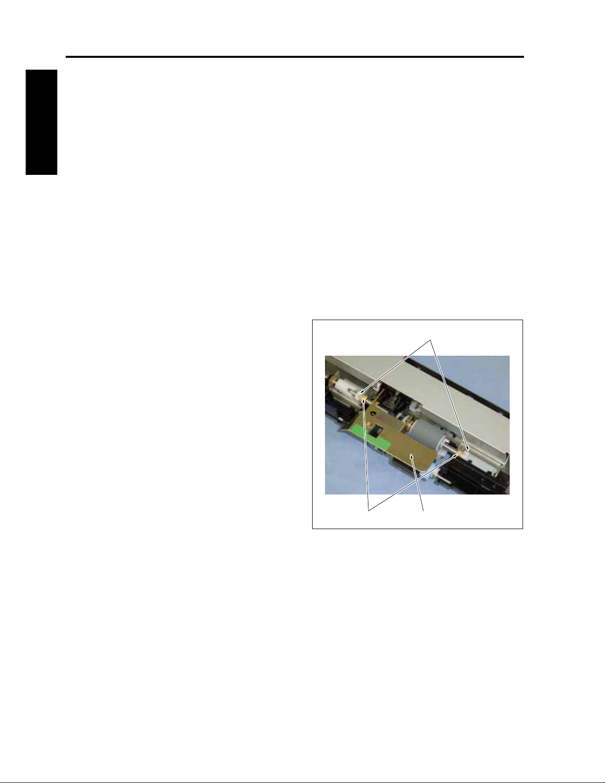
PAPER FEED TRAYS /1 to /3 CF5001 Field Service Ver.1.0 Sep 2003
6.3 Replacing the paper feed roller and the feed rubber
A. Periodically replaced parts/cycle
• Paper feed roller: Every 2,500,000 copies (Every
800,000 copies in actual replacement count)
I DIS./ASSEMBLY
• Feed rubber: Every 400,000 copies (Every
125,000 copies in actual replacement count)
B. Procedure
Note:
• Since the composition of the paper feed trays
/1 to /3 is the same, the explanation here is
made of the steps for the paper feed tray /1.
1. Pull out the paper feed tray /1.
2. Remove the paper feed unit.
3. Remove 2 stop rings [1], slide 2 bearings [2] to
the outside and then remove the paper feed
roller assembly [3].
[1]
1-58
[2] [3]
8050ma3163
Page 89
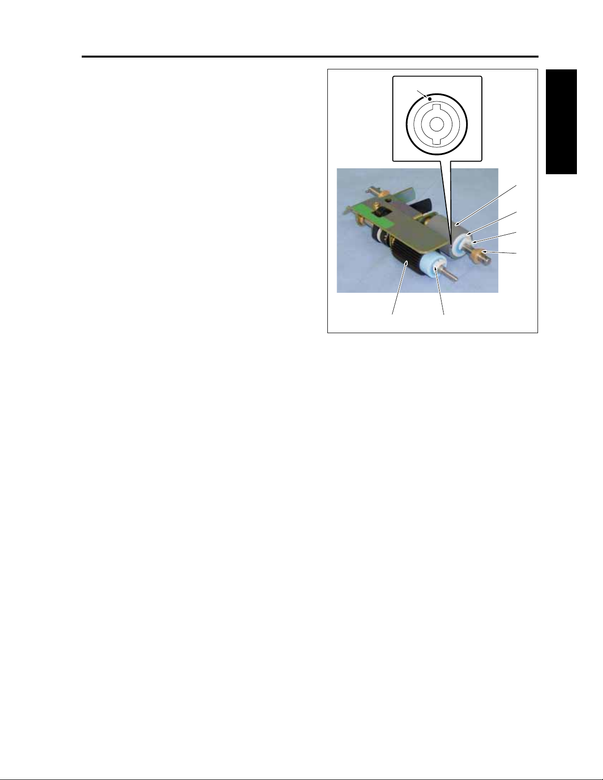
CF5001 Field Service Ver.1.0 Sep 2003 PAPER FEED TRAYS /1 to /3
4. Remove a bearing [1].
5. Remove a stop ring [2] and then remove the
[7]
paper feed roller [3].
6. Remove a stop ring [4] and then remove the
feed roller [5].
7. Remove the feed rubber [6] from the feed roller
[5].
8. Reinstall the above parts following the removal
steps in reverse.
[6]
I DIS./ASSEMBLY
Note:
• Be sure to install the feed rubber [6] so that
the paint mark [7] turns in the arrow-marked
direction.
• Be sure to check that each roller is not stuck
with grease.
[5]
[4]
[1]
[2][3]
8050ma3164
1-59
Page 90

PAPER FEED TRAYS /1 to /3 CF5001 Field Service Ver.1.0 Sep 2003
6.4 Replacing the double feed prevention rubber
A. Periodically replaced parts/cycle
• Double feed prevention rubber: Every 400,000
copies (Every 125,000 copies in actual replace-
I DIS./ASSEMBLY
ment count)
B. Procedure
Note:
• Since the composition of the paper feed trays
/1 to /3 is the same, the explanation here is
made of the steps for the paper feed tray /1.
1. Pull out the paper feed tray /1.
2. Remove the paper feed unit.
3. Remove the paper feed roller assembly.
4. Remove a stop ring [1] and then remove the
double feed prevention roller [2].
5. Remove the gear [3] from the double feed pre-
vention roller [2].
6. Remove the double feed prevention rubber [4]
from the double feed prevention roller [2].
7. Reinstall the above parts following the removal
steps in reverse.
[5]
Note:
• Be sure to install the double feed prevention
rubber [4] so that the paint mark [5] turns in
the arrow-marked direction.
• Be sure to check that the double feed preven-
tion roller is not stuck with grease.
[1]
[2][4][3]
8050ma3165
1-60
Page 91
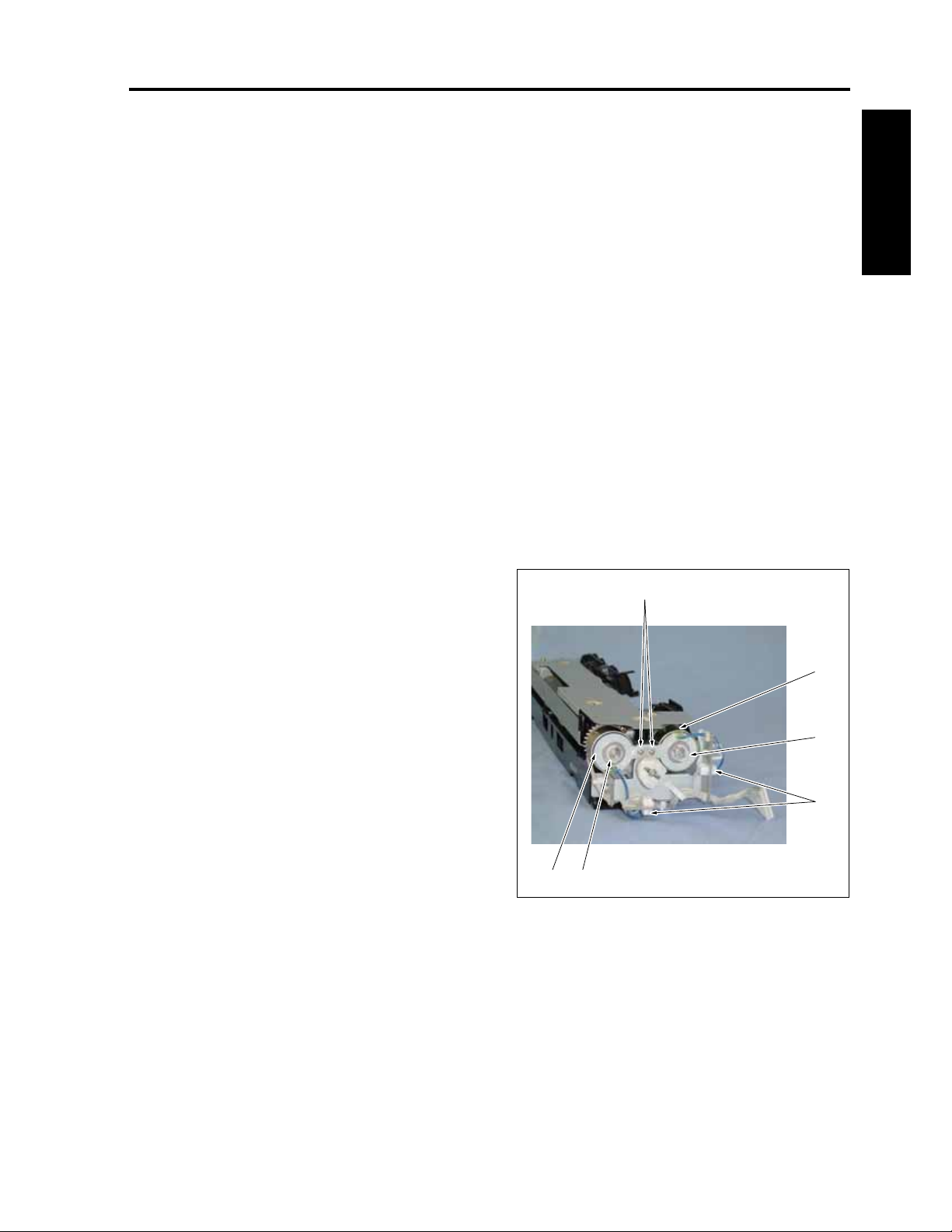
CF5001 Field Service Ver.1.0 Sep 2003 PAPER FEED TRAYS /1 to /3
6.5 Replacing the paper feed
clutch and the pre-registration clutch
A. Periodically replaced parts/cycle
• Paper feed clutches /1 to /3 (MC7, MC9, MC11):
Every 4,000,000 copies (Every 2,000,000 copies
in actual replacement count)
• Pre-registration clutches /1 to /3 (MC8, MC10,
MC13): Every 4,000,000 copies (Every
2,000,000 copies in actual replacement count)
B. Procedure
Note:
• Since the composition of the paper feed trays
/1 to /3 is the same, the explanation here is
made of the steps for the paper feed tray /1.
I DIS./ASSEMBLY
1. Pull out the paper feed tray /1.
2. Remove the paper feed unit.
3. Remove 2 connectors [1].
4. Remove a stop ring [2] and then remove the
MC7 [3].
5. Remove a stop ring [4] and then remove the
MC8 [5].
6. Reinstall the above parts following the removal
steps in reverse.
Note:
• When reinstalling the clutches, be sure to
check that the stopper [6] of each clutch is in
the specified position.
[5] [4]
[6]
[3]
[2]
[1]
8050ma3166
1-61
Page 92

PAPER FEED TRAYS /1 to /3 CF5001 Field Service Ver.1.0 Sep 2003
6.6 Removing and reinstalling the tray up/down wire
Wire length:
• Up/down wire /A and up/down wire /C: 531mm
• Up/down wire /B and up/down wire /D: 160mm
I DIS./ASSEMBLY
A. Removing the wire
Note:
• Since the composition of the paper feed trays
/1 to /3 is the same, the explanation here is
made of the steps for the paper feed tray /1.
1. Pull out the paper feed tray /1.
2. Remove the paper feed unit.
3. Remove the paper feed tray /1.
4. Remove 3 screws [1] and then remove the wire
cover /FR [2].
5. Remove 2 screws [3] and then remove the wire
cover /FL [4].
6. Remove 3 screws [5] and then remove the wire
cover /RR [6].
7. Remove 2 screws [7] and then remove the wire
cover /RL [8].
[5][7] [6] [2]
[1]
[3]
[4][8]
8050ma3167
1-62
Page 93

CF5001 Field Service Ver.1.0 Sep 2003 PAPER FEED TRAYS /1 to /3
8. Remove an E-ring [1].
9. Slide the drive pulley [2] to the inside and
remove the wires /C [3] and /D [4].
10. After removing an E-ring [5], remove the pulley
[6] and release the wires /C [3] and /D [4] from
the wire restraining cover [7].
11. Remove a screw [8] from the bottom of the
paper feed tray /1 and then remove the wire /D
[4].
12. After removing an E-ring [9], remove the pulley
[10] and release the wire /C [3] from the wire
restraining cover [11].
13. Remove a screw [12] from the bottom of the
paper feed tray /1 and then remove the wire /C
[3].
[9]
[11]
[10]
14. Remove an E-ring [13].
15. Slide the drive pulley [14] to the inside and
remove the wires /A [15] and /B [16].
16. After removing an E-ring [17], remove the pulley
[18] and release the wires /A [15] and /B [16]
from the wire restraining cover [19].
17. Remove a screw [20] from the bottom of the
paper feed tray /1 and then remove the wire /B
[16].
18. After removing an E-ring [21], remove the pulley
[22] and release the wire /A [15] from the wire
restraining cover [23].
19. Remove a screw [24] from the bottom of the
paper feed tray /1 and then remove the wire /A
[15].
[7]
[6]
[3]
[5]
I DIS./ASSEMBLY
[21]
[3]
[8]
[4]
[1]
[2][12]
[19][22][23] [18]
[17]
[15]
[20]
[16]
1-63
[13][14][24][15]
8050ma3168
Page 94

PAPER FEED TRAYS /1 to /3 CF5001 Field Service Ver.1.0 Sep 2003
B. Attaching the wire
4. After winding the wire /C [3] and the wire /D [10]
around the pulley [11], insert it into the shaft [13]
Note:
• Since the composition of the paper feed trays
together with the wire restraining cover [12] and
fasten it with an E-ring [14].
/1 to /3 is the same, the explanation here is
made of the steps for the paper feed tray /1.
I DIS./ASSEMBLY
1. Install the wire /C [3] to the wire holding shaft [2]
with a screw [1] from the bottom side of the
Note:
• Be sure to wind the wires around the pulley
[11] so that the wire /C [3] comes to the out-
side and the wire /D [10] to the inside.
paper feed tray.
2. After winding the wire /C [3] around the pulley
[4], insert it into the shaft [6] together with the
wire restraining cover [5] and fasten it with an E-
ring [7].
5. After sliding the drive pulley [15] to the outside
with the wire /C [3] and the wire /D [10] inserted
into the up/down drive shaft [14], fasten it with
an E-ring [16].
3. Install the wire /D [10] to the wire holding shaft
[9] with a screw [8] from the bottom side of the
paper feed tray.
[12]
[7]
[5]
[4]
[11]
[4]
[13]
[3]
[6]
[3]
[8]
[9]
[16]
[17]
[18]
[10]
[15][14][1][2]
[17]
8050ma3169
1-64
Page 95

CF5001 Field Service Ver.1.0 Sep 2003 PAPER FEED TRAYS /1 to /3
Note:
• Be sure to wind the wires around the pulley
[14] so that the wire /C [3] comes to the out-
side and the wire /D [10] to the inside.
6. Install the wires /A [17] and /B [18] by following
Steps 1 to 5.
Note:
• After completion of attaching the wires, be
sure to rotate the up/down drive shaft by hand
to check to see if the up/down plate goes up
and down smoothly.
7. For the subsequent steps, reinstall the parts fol-
lowing the removal steps in reverse.
I DIS./ASSEMBLY
1-65
Page 96
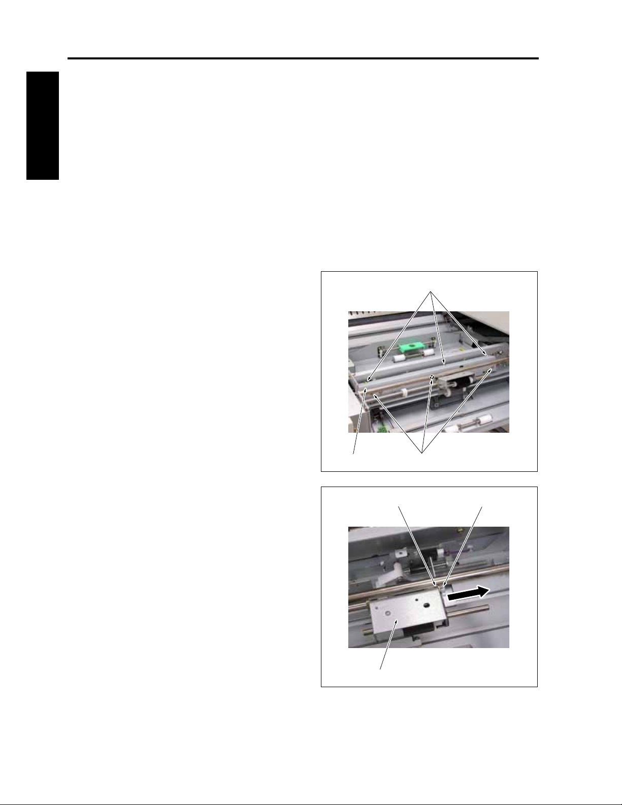
BY-PASS TRAY CF5001 Field Service Ver.1.0 Sep 2003
7. BY-PASS TRAY
7.1 Replacing the paper feed roller and the feed roller
A. Periodically replaced parts/cycle
I DIS./ASSEMBLY
• Paper feed roller: Every 800,000 copies in actual
replacement count
• Feed roller: Every 125,000 copies in actual
replacement count
B. Procedure
1. Pull out the ADU. (See "10.1 Removing and
reinstalling the ADU.")
2. Remove 6 screws [1] and then remove the
paper feed solenoid cover [2].
[1]
3. Remove the stop ring [1].
4. Remove the bearing [2] and then remove the
paper feed roller unit [3].
[3]
[1][2]
8050ma3075
[1][2]
8050ma3076
1-66
Page 97
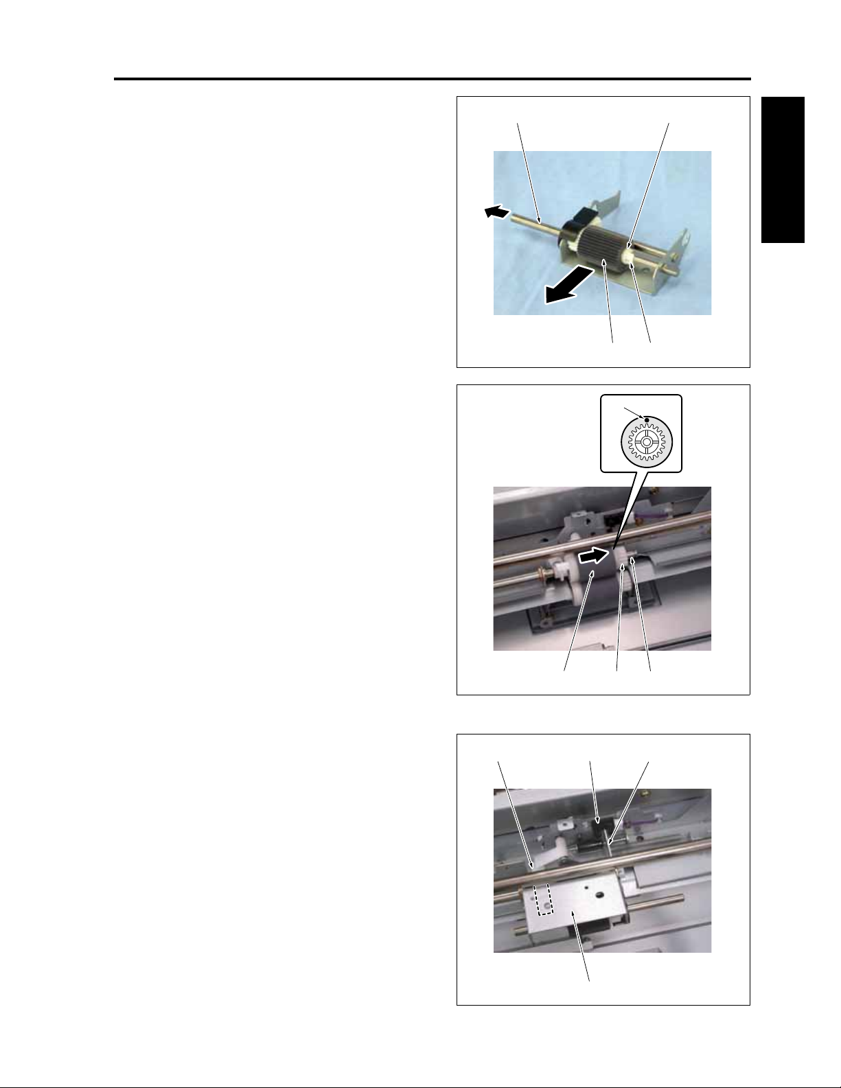
CF5001 Field Service Ver.1.0 Sep 2003 BY-PASS TRAY
5. After removing the stop ring [1], pull out the feed
shaft [2] and remove the paper feed gear
[3][2]
assembly [3].
6. Remove the paper feed roller [4] from the paper
feed gear assembly [3].
I DIS./ASSEMBLY
7. Remove the feed roller assembly [2] from the
by-pass drive shaft [1].
8. Remove the feed roller [3] from the feed roller
assembly [2].
Note:
• Be sure to install the feed roller [3] so that the
paint mark [4] turns in the direction shown in
the drawling.
9. Reinstall the above parts following the removal
steps in reverse.
Note:
• Be sure to install the paper feed roller unit [1]
so that the actuator section [2] coincides with
the detection section of the PS47 (no paper
sensor /BP) [3].
• Be sure to install the paper feed roller unit [1]
so that the tip end of the paper feed side of
the paper up/down lever comes into contact
with the inside of the top plate of the paper
feed roller unit [1].
[3] [2][4]
[4] [1]
[4]
[2] [1][3]
8050ma3077
8050ma3078
1-67
[1]
8050ma3079
Page 98
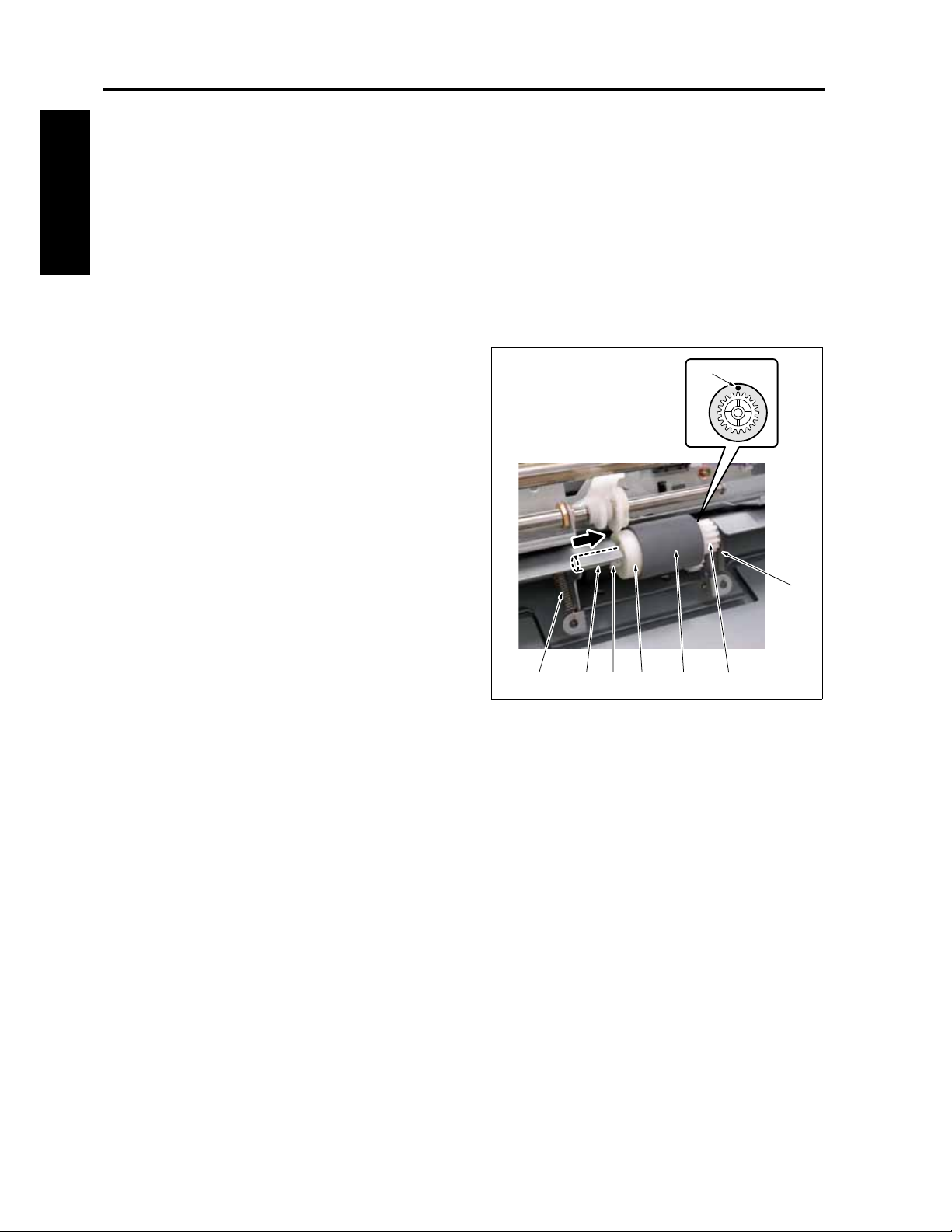
BY-PASS TRAY CF5001 Field Service Ver.1.0 Sep 2003
7.2 Replacing the double feed prevention roller
A. Periodically replaced parts/cycle
• Double feed prevention roller: Every 125,000
copies in actual replacement count
I DIS./ASSEMBLY
B. Procedure
1. Remove the paper feed roller and the feed roller.
(See "Replacing the paper feed roller and the
feed roller.")
2. Remove 2 double feed pressure springs [1].
3. After removing the stop ring [2], pull out the dou-
ble feed prevention shaft [3] and remove the
flange [4] and the double feed prevention roller
assembly [5].
4. Remove the double feed prevention roller [6]
from the double feed prevention roller assembly
[5].
5. Reinstall the above parts following the removal
steps in reverse.
[7]
Note:
• Be sure to install the double feed prevention
roller [6] so that the paint mark [7] turns in the
direction shown in the drawing.
[1]
[2][3][1]
[6][4] [5]
8050ma3080
1-68
Page 99
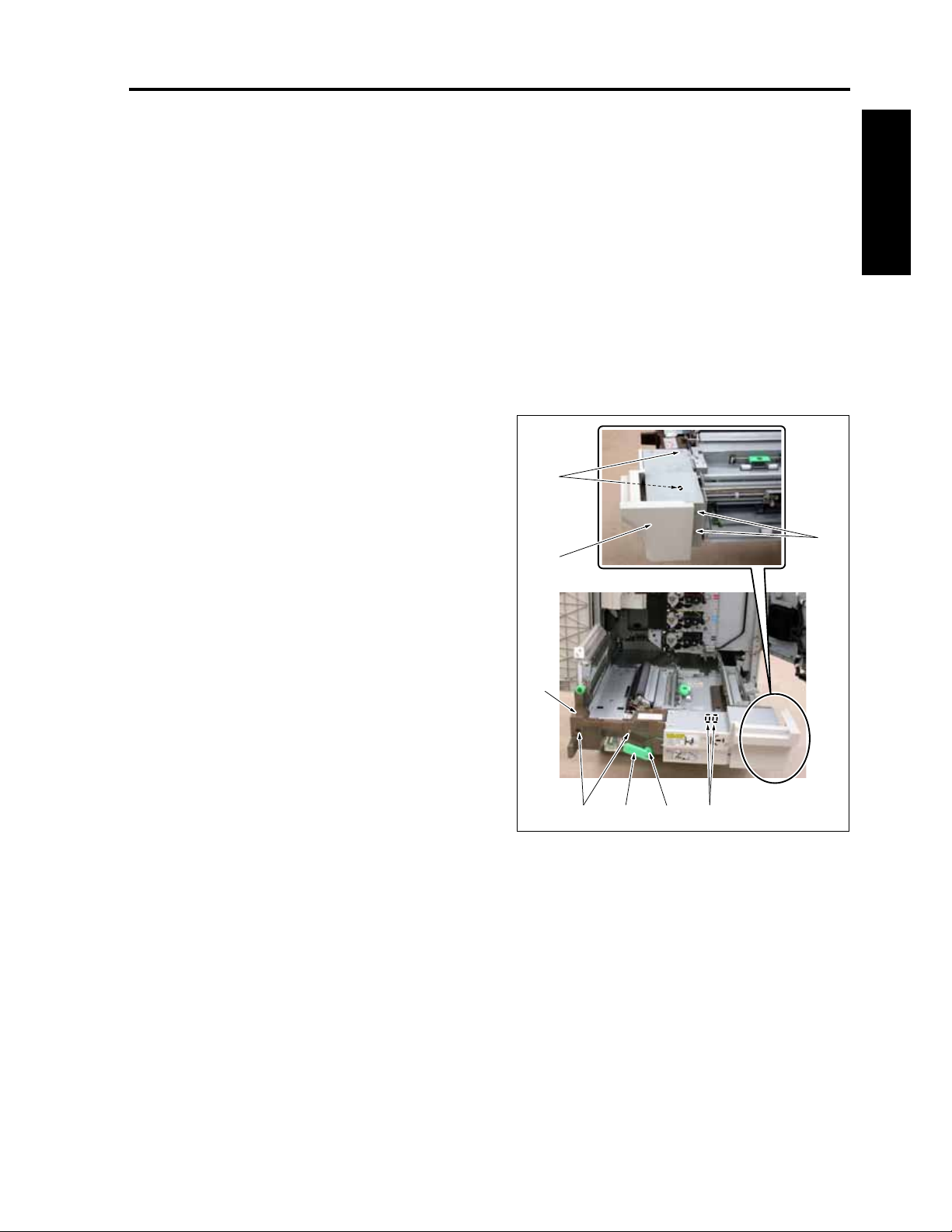
CF5001 Field Service Ver.1.0 Sep 2003 BY-PASS TRAY
7.3 Replacing the paper feed
clutch /BP
A. Periodically replaced parts/cycle
• Paper feed clutch /BP (MC6): Every 2,000,000
copies in actual replacement count
B. Procedure
1. Open the toner supply section. (See "5.1 Open-
ing and closing the toner supply section.")
2. Pull out the ADU. (See "10.1 Removing and
reinstalling the ADU.")
3. Remove the fixing unit. (See "9.2 Removing and
reinstalling the fixing unit.")
4. Remove 4 screws [1]. (One of the screws is
installed on the underside of the ADU cover/R
[2].)
5. After pulling out the ADU cover /R [2] halfway,
remove 2 relay connectors [3] and then remove
the ADU cover /R [2].
6. Remove the screw [4] and then remove the
stand pulling lever [5].
7. Remove 2 screws [6] and then remove the ADU
cover /L [7].
[1]
[1]
[2]
I DIS./ASSEMBLY
[7]
[4]
[3][5][6]
8050ma3081
1-69
Page 100
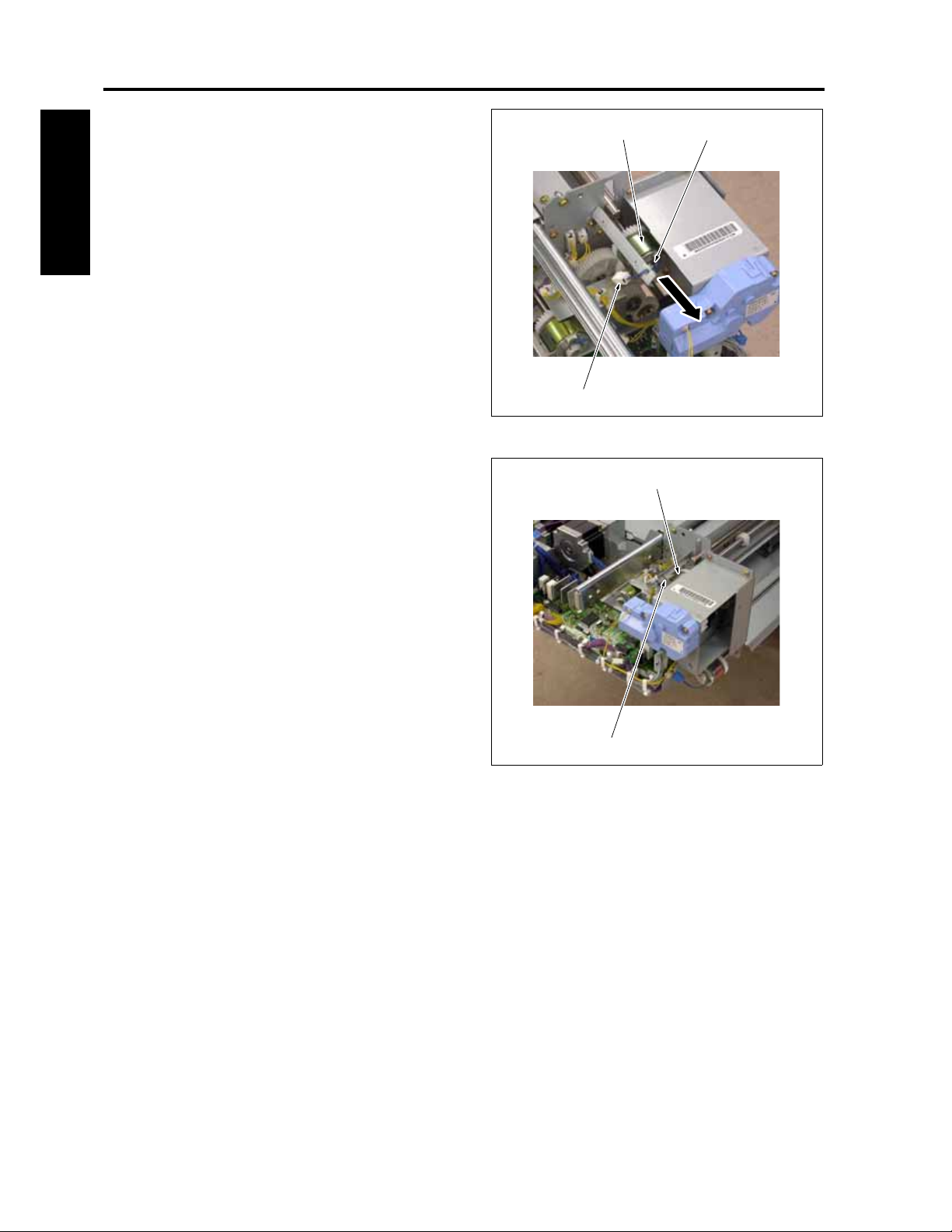
BY-PASS TRAY CF5001 Field Service Ver.1.0 Sep 2003
8. Remove a relay connector [1].
9. Remove the stop ring [2] and then remove the
[2][3]
paper feed clutch /BP (MC6) [3].
10. Reinstall the above parts following the removal
steps in reverse.
I DIS./ASSEMBLY
Note:
• When reinstalling the paper feed clutch /BP
(MC6) [1], be sure to set the stopper in the
detente groove [2].
[1]
[2]
8050ma3082
[1]
8050ma3083
1-70
 Loading...