

KONICA MINOLTA CF2002CF3102 Service Manual

Service Manual
CF2002/CF3102

1. SAFETY PRECAUTIONS FOR INSPECTION AND
SERVICE
• When performing inspection and service procedures, observe the following precautions
to prevent accidents and ensure utmost safety.
✽ Depending on the model, some of the precautions given in the following do not apply.
• Different markings are used to denote specific meanings as detailed below.
WARNING
• Indicates a potentially hazardous situation which, if not avoided, may result in minor or
moderate injury. It may also be used to alert against unsafe practices.
CAUTION
• The following graphic symbols are used to give instructions that need to be observed.
Used to call the service technician attention to what is graphically represented
inside the marking (including a warning).
Used to prohibit the service technician from doing what is graphically represented
inside the marking.
Used to instruct the service technician to do what is graphically represented
inside the marking.
1-1. Warning
WARNING
1. Always observe precautions.
• Parts requiring special attention in this product will include a label containing
the mark shown on the left plus precautionary notes. Be sure to observe the
precautions.
• Be sure to observe the “Safety Information” given in the Operator’s Manual.
2. Before starting the procedures, be sure to unplug the power cord.
• This product contains a high-voltage unit and a circuit with a large current
capacity that may cause an electric shock or burn.
• The product also contains parts that can jerk suddenly and cause injury.
• If this product uses a laser, laser beam leakage may cause eye damage or
blindness.
P-1
WARNING
3. Do not throw toner or the toner bottle into a fire.
• Do not throw toner or the Toner Bottle (Imaging Cartridge, Toner Cartridge) into
a fire. Toner expelled from the fire may cause burns.
4. Use the specified parts.
• For replacement parts, always use the genuine parts specified in the manufacturer’s parts manual. Installing a wrong or unauthorized part could cause
dielectric breakdown, overload, or undermine safety devices resulting in possible electric shock or fire.
• Replace a blown electrical fuse or thermal fuse with its corresponding genuine
part specified in the manufacturer’s parts manual. Installing a fuse of a different make or rating could lead to a possible fire. If a thermal fuse blows frequently, the temperature control system may have a problem and action must
be taken to eliminate the cause of the problem.
5. Handle the power cord with care and never use a multiple outlet.
• Do not break, crush or otherwise damage the power cord. Placing a heavy
object on the power cord, or pulling or bending it may damage it, resulting in a
possible fire or electric shock.
• Do not use a multiple outlet to which any other appliance or machine is connected.
• Be sure the power outlet meets or exceeds the specified capacity.
6. Be careful with the high-voltage parts.
• A part marked with the symbol shown on the left carries a high voltage. Touching it could result in an electric shock or burn. Be sure to unplug the power cord
before servicing this part or the parts near it.
7. Do not work with wet hands.
• Do not unplug or plug in the power cord, or perform any kind of service or
inspection with wet hands. Doing so could result in an electric shock.
8. Do not touch a high-temperature part.
• A part marked with the symbol shown on the left and other parts such as the
exposure lamp and fusing roller can be very hot while the machine is energized. Touching them may result in a burn.
• Wait until these parts have cooled down before replacing them or any surrounding parts.
P-2
WARNING
9. Maintain a grounded connection at all times.
• Connect the power cord to an electrical outlet that is equipped with a grounding terminal.
10. Do not remodel the product.
• Modifying this product in a manner not authorized by the manufacturer may
result in a fire or electric shock. If this product uses a laser, laser beam leakage
may cause eye damage or blindness.
11. Restore all parts and harnesses to their original positions.
• To promote safety and prevent product damage, make sure the harnesses are
returned to their original positions and properly secured in their clamps and
saddles in order to avoid hot parts, high-voltage parts, sharp edges, or being
crushed.
• To promote safety, make sure that all tubing and other insulating materials are
returned to their original positions. Make sure that floating components
mounted on the circuit boards are at their correct distance and position off the
boards.
1-2. Caution
CAUTION
1. Precautions for Service Jobs.
• A star washer and spring washer, if used originally, must be reinstalled. Omitting them may result in contact failure which could cause an electric shock or
fire.
• When reassembling parts, make sure that the correct screws (size, type) are
used in the correct places. Using the wrong screw could lead to stripped
threads, poorly secured parts, poor insulating or grounding, and result in a malfunction, electric shock or injury.
• Take great care to avoid personal injury from possible burrs and sharp edges
on the parts, frames and chassis of the product.
• When moving the product or removing an option, use care not to injure your
back or allow your hands to be caught in mechanisms.
P-3
CAUTION
2. Precautions for Servicing with Covers and Parts Removed.
• Wherever feasible, keep all parts and covers mounted when energizing the
product.
• If energizing the product with a cover removed is absolutely unavoidable, do
not touch any exposed live parts and use care not to allow your clothing to be
caught in the moving parts. Never leave a product in this condition unattended.
• Never place disassembled parts or a container of liquid on the product. Parts
falling into, or the liquid spilling inside, the mechanism could result in an electric shock or fire.
• Never use a flammable spray near the product. This could result in a fire.
• Make sure the power cord is unplugged before removing or installing circuit
boards or plugging in or unplugging connectors.
• Always use the interlock switch actuating jig to actuate an interlock switch
when a cover is opened or removed. The use of folded paper or some other
object may damage the interlock switch mechanism, possibly resulting in an
electric shock, injury or blindness.
3. Precautions for the Working Environment.
• The product must be placed on a flat, level surface that is stable and secure.
• Never place this product or its parts on an unsteady or tilting workbench when
servicing.
• Provide good ventilation at regular intervals if a service job must be done in a
confined space for a long period of time.
• Avoid dusty locations and places exposed to oil or steam.
• Avoid working positions that may block the ventilation ports of the product.
4. Precautions for Handling Batteries. (Lithium, Nickel-Cadmium, etc.)
• Replace a rundown battery with the same type as specified in the manufacturer’s parts manual.
• Before installing a new battery, make sure of the correct polarity of the installation or the battery could burst.
• Dispose of used batteries according to the local regulations. Never dispose of
them at the user’s premises or attempt to try to discharge one.
5. Precautions for the Laser Beam. (Only for Products Employing a Laser)
• Removing the cover marked with the caution label could lead to possible exposure to the laser beam, resulting in eye damage or blindness. Be sure to
unplug the power cord before removing this cover.
• If removing this cover while the power is ON is unavoidable, be sure to wear
protective laser goggles that meet specifications.
• Make sure that no one enters the room when the machine is in this condition.
• When handling the laser unit, observe the “Precautions for Handling Laser
Equipment.”
6. Precautions for storing the toner or imaging cartridge.
• Be sure to keep the toner or imaging cartridge out of the reach of children.
Licking the imaging cartridge or ingesting its contents is harmful to your health.
P-4

1-3. Used Batteries Precautions
ALL Areas
Danger of explosion if battery is incorrectly replaced.
Replace only with the same or equivalent type recommended by the manufacturer.
Dispose of used batteries according to the manufacturer’s instructions.
CAUTION
Germany
Explosionsgefahr bei unsachgemäßem Austausch der Batterie.
Ersatz nur durch denselben oder einen vom Hersteller empfohlenen gleichwertigen Typ.
Entsorgung gebrauchter Batterien nach Angaben des Herstellers.
France
Il y a danger d’explosion s’il y a remplacement incorrect de la batterie.
Remplacer uniquement avec une batterie du même type ou d’un type équivalent recommandé par le constructeur.
Mettre au rebut les batteries usagées conformément aux instructions du fabricant.
Denmark
Lithiumbatteri - Eksplosionsfare ved fejlagtig håndtering.
Udskiftning må kun ske med batteri af samme fabrikat og type.
Levér det brugte batteri tilbage til leverandøren.
Finland, Sweden
Paristo voi räjähtää, jos se on virheellisesti asennettu.
Vaihda paristo ainoastaan laitevalmistajan suosittelemaan tyyppiin.
Hävitä käytetty paristo valmistajan ohjeiden mukaisesti.
Explosionsfara vid felaktigt batteribyte.
Använd samma batterityp eller en ekvivalent typ som rekommenderas av apparattillverkaren.
Kassera använt batteri enligt fabrikantens instruktion.
VORS ICHT!
ATTENTION
ADVARSEL!
VAROlTUS
VAR NI NG
Norway
Eksplosjonsfare ved feilaktig skifte av batteri.
Benytt samme batteritype eller en tilsvarende type anbefalt av apparatfabrikanten.
Brukte batterier kasseres i henhold til fabrikantens instruksjoner.
ADVARSEL
P-5

1-4. Other Precautions
• When handling circuit boards, observe the “HANDLING of PWBs”.
• The PC Drum is a very delicate component. Observe the precautions given in “HANDLING OF THE PC DRUM” because mishandling may result in serious image problems.
• Note that replacement of a circuit board may call for readjustments or resetting of particular items, or software installation.
1-5. Precautions for Service
• When performing inspection and service procedures, observe the following precautions
to prevent mishandling of the machine and its parts.
✽ Depending on the model, some of the precautions given in the following do not apply.
1. Precautions Before Service
• When the user is using a word processor or personal computer from a wall outlet of the
same line, take necessary steps to prevent the circuit breaker from opening due to overloads.
• Never disturb the LAN by breaking or making a network connection, altering termination,
installing or removing networking hardware or software, or shutting down networked
devices without the knowledge and express permission of the network administrator or
the shop supervisor.
2. How to Use this Book
DIS/REASSEMBLY, ADJUSTMENT
• To reassemble the product, reverse the order of disassembly unless otherwise specified.
TROUBLESHOOTING
• If a component on a PWB or any other functional unit including a motor is defective, the
text only instructs you to replace the whole PWB or functional unit and does not give troubleshooting procedures applicable within the defective unit.
• All troubleshooting procedures contained herein assume that there are no breaks in the
harnesses and cords and all connectors are plugged into the right positions.
• The procedures preclude possible malfunctions due to noise and other external causes.
3. Precautions for Service
• Keep all disassembled parts in good order and keep tools under control so that none will
be lost or damaged.
• After completing a service job, perform a safety check. Make sure that all parts, wiring
and screws are returned to their original positions.
• Do not pull out the toner hopper while the toner bottle is turning. This could result in a
damaged motor or locking mechanism.
• If the product is to be run with the front door open, make sure that the toner hopper is in
the locked position.
• Do not use an air gun or vacuum cleaner for cleaning the ATDC Sensor and other sensors, as they can cause electrostatic destruction. Use a blower brush and cloth. If a unit
containing these sensors is to be cleaned, first remove the sensors from the unit.
P-6

4. Precautions for Dis/Reassembly
• Be sure to unplug the copier from the outlet before attempting to service the copier.
• The basic rule is not to operate the copier anytime during disassembly. If it is absolutely
necessary to run the copier with its covers removed, use care not to allow your clothing to
be caught in revolving parts such as the timing belt and gears.
• Before attempting to replace parts and unplug connectors, make sure that the power
cord of the copier has been unplugged from the wall outlet.
• Be sure to use the Interlock Switch Actuating Jig whenever it is necessary to actuate the
Interlock Switch with the covers left open or removed.
• While the product is energized, do not unplug or plug connectors into the circuit boards
or harnesses.
• Never use flammable sprays near the copier.
• A used battery should be disposed of according to the local regulations and never be discarded casually or left unattended at the user’s premises.
• When reassembling parts, make sure that the correct screws (size, type) and toothed
washer are used in the correct places.
5. Precautions for Circuit Inspection
• Never create a closed circuit across connector pins except those specified in the text and
on the printed circuit.
• When creating a closed circuit and measuring a voltage across connector pins specified
in the text, be sure to use the GND wire.
6. Handling of PWBs
During Transportation/Storage
• During transportation or when in storage, new P.W. Boards must not be indiscriminately
removed from their protective conductive bags.
• Do not store or place P.W. Boards in a location exposed to direct sunlight and high temperature.
• When it becomes absolutely necessary to remove a Board from its conductive bag or
case, always place it on its conductive mat in an area as free as possible from static electricity.
• Do not touch the pins of the ICs with your bare hands.
• Protect the PWBs from any external force so that they are not bent or damaged.
During Inspection/Replacement
• Avoid checking the IC directly with a multimeter; use connectors on the Board.
• Never create a closed circuit across IC pins with a metal tool.
• Before unplugging connectors from the P.W. Boards, make sure that the power cord has
been unplugged from the outlet.
• When removing a Board from its conductive bag or conductive case, do not touch the
pins of the ICs or the printed pattern. Place it in position by holding only the edges of the
Board.
• When touching the PWB, wear a wrist strap and connect its cord to a securely grounded
place whenever possible. If you cannot wear a wrist strap, touch a metal part to discharge static electricity before touching the PWB.
• Note that replacement of a PWB may call for readjustments or resetting of particular
items.
7. Handling of Other Parts
• The magnet roller generates a strong magnetic field. Do not bring it near a watch, floppy
disk, magnetic card, or CRT tube.
P-7
8. Handling of the PC Drum
✽ Only for Products Not Employing an Imaging Cartridge.
During Transportation/Storage
• Use the specified carton whenever moving or storing the PC Drum.
• The storage temperature is in the range between –20°C and +40°C.
• In summer, avoid leaving the PC Drum in a car for a long time.
Handling
• Ensure that the correct PC Drum is used.
• Whenever the PC Drum has been removed from the copier, store it in its carton or protect
it with a Drum Cloth.
• The PC Drum exhibits greatest light fatigue after being exposed to strong light over an
extended period of time. Never, therefore, expose it to direct sunlight.
• Use care not to contaminate the surface of the PC Drum with oil-base solvent, fingerprints, and other foreign matter.
• Do not scratch the surface of the PC Drum.
• Do not apply chemicals to the surface of the PC Drum.
• Do not attempt to wipe clean the surface of the PC Drum.
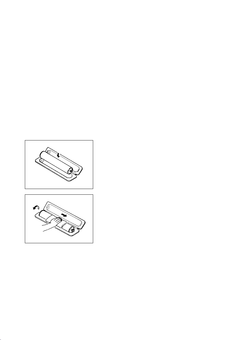
If, however, the surface is contaminated with fingerprints, clean it using the following procedure.
A. Place the PC Drum into one half of its carton.
1076D001
1076D002
B. Gently wipe the residual toner off the surface of the
PC Drum with a dry, Dust-Free Cotton Pad.
• Turn the PC Drum so that the area of its surface on
which the line of toner left by the Cleaning Blade is
present is facing straight up. Wipe the surface in one
continuous movement from the rear edge of the PC
Drum to the front edge and off the surface of the PC
Drum.
• Turn the PC Drum slightly and wipe the newly
exposed surface area with a CLEAN face of the
Dust-Free Cotton Pad. Repeat this procedure until
the entire surface of the PC Drum has been thoroughly cleaned.
✽ At this time, always use a CLEAN face of the dry
Dust-Free Cotton Pad until no toner is evident on the
face of the Pad after wiping.
P-8
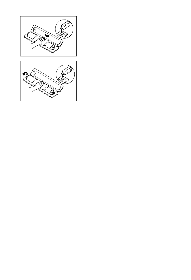
C. Soak a small amount of either ethyl alcohol or iso-
propyl alcohol into a clean, unused Dust-Free Cotton Pad which has been folded over into quarters.
Now, wipe the surface of the PC Drum in one continuous movement from its rear edge to its front
edge and off its surface one to two times.
✽ Never move the Pad back and forth.
1076D003
D. Using the SAME face of the Pad, repeat the proce-
dure explained in the latter half of step 3 until the
entire surface of the PC Drum has been wiped.
Always OVERLAP the areas when wiping. Two
complete turns of the PC Drum would be appropriate for cleaning.
1076D004
NOTES
• Even when the PC Drum is only locally dirtied, wipe the entire surface.
• Do not expose the PC Drum to direct sunlight. Clean it as quickly as possible even under
interior illumination.
• If dirt remains after cleaning, repeat the entire procedure from the beginning one more
time.
9. Handling of the Imaging Cartridge
✽ Only for Products Employing an Imaging Cartridge.
During Transportation/Storage
• The storage temperature is in the range between –20 °C and +40 °C.
• In summer, avoid leaving the Imaging Cartridge in a car for a long time.
• Never store the Imaging Cartridge on it’s end.
Handling
• Store the Imaging Cartridge in a place that is not exposed to direct sunlight.
Precautionary Information on the PC Drum Inside the Imaging Cartridge
• Use care not to contaminate the surface of the PC Drum with oil-base solvent, fingerprints, and other foreign matter.
• Do not scratch the surface of the PC Drum.
• Do not attempt to wipe clean the surface of the PC Drum.
P-9


INDEX
GENERAL
MAINTENANCE
DIS/REASSEMBLY,
ADJUSTMENT
SWITCHES ON PWBs,
TECH. REP. SETTINGS
TROUBLESHOOTING


CONTENTS
GENERAL
1. SPECIFICATION ............................................................................................. G-1
2. PRECAUTIONS FOR INSTALLATION ............................................................ G-4
2-1. Installation Site ........................................................................................G-4
2-2. Power Source .......................................................................................... G-4
2-3. Grounding ................................................................................................ G-4
3. PRECAUTIONS FOR USE ..............................................................................G-5
3-1. To ensure that the copier is used in an optimum condition .....................G-5
3-2. Operating Environment ............................................................................ G-5
3-3. Power Requirements ............................................................................... G-5
3-4. Note ......................................................................................................... G-5
4. HANDLING OF CONSUMABLES .................................................................... G-6
5. OTHER PRECAUTIONS .................................................................................G-7
6. LED RADIATION SAFETY ..............................................................................G-7
7. SYSTEM OPTIONS ......................................................................................... G-8
MAINTENANCE
1. MAINTENANCE SCHEDULE .......................................................................... E-1
1-1. Guideline for Life Specifications Values by Unit ...................................... E-3
2. DISASSEMBLY/REASSEMBLY AND CLEANING .......................................... E-5
(1) Cleaning of the Paper Take-Up Roller ............................................. E-5
(2) Replacing of the Paper Take-Up Roller ...........................................E-5
(3) Cleaning of the Paper Separator Roller ........................................... E-5
(4) Replacing of the Separator Roll Assy ..............................................E-6
(5) Cleaning of the Synchronizing Rollers ............................................. E-7
(6) Cleaning of the Paper Dust Remover ..............................................E-7
(7) Replacing of the Paper Dust Remover ............................................ E-8
(8) Cleaning of the Transport Roller ...................................................... E-8
(9) Cleaning of the 2nd Image Transfer Entrance Upper Guide ...........E-8
(10) Cleaning of the Scanner Rails .........................................................E-9
(11) Cleaning of the Mirrors (1st/2nd/3rd) ............................................... E-10
(12) Cleaning of the Lens ........................................................................E-11
(13) Cleaning of the Original Glass ......................................................... E-11
(14) Cleaning of the CCD Sensor ...........................................................E-12
(15) Replacing the Waste Toner Bottle ................................................... E-13
(16) Cleaning of the Area around the Waste Toner Collecting Port ........ E-14
(17) Replacing Ozone Filter ....................................................................E-15
(18) Cleaning of the Comb Electrode ......................................................E-15
(19) Cleaning LPH Assy .......................................................................... E-16
(20) Cleaning of the Fusing Entrance Guide Plate .................................E-17
(21) Replacement of the Deodorant Filter ............................................... E-17
3. Replacing the Units .......................................................................................... E-18
(1) Replacing the Image Transfer Roller Unit ....................................... E-18
(2) Replacing the Image Transfer Belt Unit ........................................... E-19
(3) Replacing the Imaging Unit (C, M, Y, Bk) ........................................E-22
i

(4) Replacing the Fusing Unit ............................................................... E-26
DIS/REASSEMBLY, ADJUSTMENT
1. SERVICE INSTRUCTIONS ............................................................................. D-1
1-1. IDENTIFICATION OF FUSES ................................................................. D-1
1-2. PARTS WHICH MUST NOT BE TOUCHED ...........................................D-2
(1) Red painted Screws ........................................................................ D-2
(2) Variable Resistors on Board ............................................................D-2
2. DISASSEMBLY/REASSEMBLY ...................................................................... D-3
2-1. DOORS, COVERS, AND EXTERIOR PARTS:
IDENTIFICATION AND REMOVAL PROCEDURES ............................... D-3
2-2. REMOVAL OF CIRCUIT BOARDS AND OTHER ELECTRICAL
COMPONENTS ....................................................................................... D-5
(1) Removal of the CCD Unit ................................................................ D-8
(2) Removal of the Image Processing Board and Image Processing
Interface Board ................................................................................ D-10
(3) Removal of the Image Control Board ..............................................D-12
(4) Removal of the High Voltage Unit (PC Drum CH.),
High Voltage Unit (Image Transfer, Neutralizing),
High Voltage Unit (Developing Bias),
and Paper Size Detecting Board ..................................................... D-13
(5) Removal of DC Power Supply 1 ...................................................... D-15
2-3. Removal of Units .....................................................................................D-16
(1) Removal of the Toner Hopper Unit .................................................. D-16
(2) Removal of the LPH Unit ................................................................. D-17
2-4. Disassembly of the IR Unit ......................................................................D-19
(1) Removal of the Scanner Motor ........................................................D-19
(2) Remove of the Scanner Assy .......................................................... D-20
(3) Removal of the Scanner Drive Cables ............................................ D-21
(4) Winding of the Scanner Drive Cables .............................................. D-23
2-5. CLEANING AND DISASSEMBLY OF THE ENGINE PARTS .................D-28
(1) Cleaning of the Transfer Belt Unit ................................................... D-28
(2) Removal of the Imaging Unit Motor C/M/Y/Bk .................................D-29
(3) Removal of the Main Motor ............................................................. D-30
(4) Removal of the Fusing Drive Motor ................................................. D-31
(5) Removal of the Fusing Pressure/Retraction Motor .......................... D-31
(6) Removal of the 1st Image Transfer Pressure/Retraction Motor ......D-33
(7) Removal of Toner Replenishing Motor C/Bk ...................................D-33
(8) Removal of Toner Replenishing Motor Y/M ..................................... D-34
(9) Removal of the 2nd Image Transfer Pressure/Retraction Motor ..... D-34
(10) Removal of the Transport Roller Motor ...........................................D-35
(11) Removal of AIDC/Registration Sensor 1/2 ...................................... D-37
(12) Removal of the LPH Assy ................................................................D-38
(13) Removal of ATDC Sensor Y/M/C .................................................... D-40
(14) Removal of the LED Drive Board ....................................................D-41
3. ADJUSTMENTS .............................................................................................. D-42
3-1. ADJUSTMENT JIGS AND TOOLS USED ............................................... D-42
ii

3-2. MECHANICAL ADJUSTMENT ................................................................ D-43
(1) Adjustment of the Scanner Motor Timing Belt ................................. D-43
(2) Focus Positioning of the Scanner and 2nd/3rd Mirrors Carriage ..... D-44
(3) Scanner Position Adjustment .......................................................... D-44
3-3. ELECTRICAL/IMAGE ADJUSTMENT ..................................................... D-45
(1) Accessing the Tech. Rep. Mode ...................................................... D-45
(2) Producing a Test Print ..................................................................... D-45
(3) Top Margin ...................................................................................... D-46
(4) Left Margin ....................................................................................... D-48
(5) Dup. Left Margin .............................................................................. D-49
(6) Zoom for FD .................................................................................... D-50
(7) Color Shift Correction ...................................................................... D-51
(8) Leading Edge Skew Adjustment ...................................................... D-53
(9) LPH Chip Adjust ..............................................................................D-54
(10) Gradation Adjust .............................................................................. D-55
(11) PRT Max Density ............................................................................. D-56
(12) PRT Highlight ..................................................................................D-57
(13) Background Voltage Margin ............................................................D-58
(14) ATDC Level Setting .........................................................................D-59
(15) AE Adjust ......................................................................................... D-60
(16) 2nd Transfer Adjust ......................................................................... D-61
(17) Fuser Temp. .................................................................................... D-62
(18) Fuser Speed ....................................................................................D-63
(19) Touch Panel Adj. ............................................................................. D-64
(20) Left Image ........................................................................................ D-65
(21) Top Image .......................................................................................D-66
(22) CD-Mag. ..........................................................................................D-67
(23) FD-Mag. ...........................................................................................D-68
(24) Org. Detect Sensor ..........................................................................D-69
4. OTHER ADJUSTMENTS ................................................................................. D-70
4-1. INSTALLATION OF THE MECHANICAL COUNTER (OPTION) ............D-70
4-2. MOUNT THE OPTIONAL ORIGINAL SIZE DETECTING SENSORS ..... D-71
4-3. FLASH MEMORY .................................................................................... D-72
4-4. REMOUNTING RAM IC (IC202) .............................................................. D-74
SWITCHES ON PWBs, TECH. REP. SETTINGS
1. FUNCTION OF SWITCHES AND OTHER PARTS ON PWBs ........................ S-1
1-1. PWB Location .......................................................................................... S-1
1-2. PWB-S1 (Tech. Rep. Setting Switches Board) ........................................ S-1
(1) Initialize Procedure .......................................................................... S-2
(2) Memory Clear Procedure ................................................................ S-2
(3) Data/Conditions Cleared by Reset Switches/Pins ...........................S-3
2. UTILITY MODE ................................................................................................ S-4
2-1. Utility Mode Function Setting Procedure .................................................S-4
2-2. Utility Mode Function Tree .......................................................................S-5
(1) Administrator Mode Function Tree ..................................................S-6
2-3. Setting in the Utility Mode ........................................................................ S-7
iii

3. TECH. REP. MODE .........................................................................................S-16
3-1. Tech. Rep. Mode Function Setting Procedure ......................................... S-16
3-2. Tech. Rep. Mode Function Tree .............................................................. S-17
3-3. Setting in the Tech. Rep. Mode ............................................................... S-20
4. SECURITY MODE ...........................................................................................S-42
4-1. Security Mode Function Setting Procedure ............................................. S-42
4-2. Security Mode Function Tree ................................................................... S-42
4-3. Settings in the Security Mode .................................................................. S-43
TROUBLESHOOTING
1. INTRODUCTION ............................................................................................. T-1
1-1. Checking the electrical components ........................................................ T-1
(1) Sensor ............................................................................................. T-1
(2) Switch ............................................................................................. T-1
(3) Solenoid ........................................................................................... T-2
(4) Clutch ............................................................................................. T-2
(5) Motor .............................................................................................T-3
1-2. I/O CHECK ..............................................................................................T-4
(1) Check Procedure .............................................................................T-4
(2) I/O Check List .................................................................................. T-5
1-3. System Control Block Diagram ................................................................ T-11
2. PAPER MISFEED ............................................................................................ T-12
2-1. Initial Check Items ...................................................................................T-12
2-2. Misfeed Display .......................................................................................T-13
2-3. Misfeed Detecting Sensor Layout ............................................................T-14
2-4. Misfeed Detection Timing/Troubleshooting Procedures .......................... T-16
(1) 1st Drawer Paper Take-Up Misfeed ................................................T-16
(2) 2nd Drawer Paper Take-Up Misfeed ............................................... T-17
(3) 3rd Drawer Paper Take-Up Misfeed (PF-118) ................................. T-18
(4) LCC Paper Take-Up Misfeed (PF-121) ...........................................T-19
(5) 4th Drawer Paper Take-Up Misfeed (PF-118) .................................T-20
(6) LCC Lift 2 to 1 paper transport Misfeed (PF121) ............................. T-21
(7) Manual Bypass Take-Up Misfeed .................................................... T-22
(8) Vertical Transport Misfeed ............................................................... T-23
(9) Duplex Paper Take-Up Misfeed (AD-14) ......................................... T-26
(10) Duplex Paper Transport Misfeed (AD-14) ....................................... T-27
(11) 2nd Image Transfer Misfeed ............................................................T-28
(12) Fusing/Exit Misfeed ......................................................................... T-29
3. MALFUNCTIONS ............................................................................................ T-30
3-1. Warning Detection Timing and Troubleshooting Procedure .................... T-31
(1) P-5: AIDC Sensor (Front) failure .....................................................T-31
(2) P-28 AIDC Sensor (Back) failure .....................................................T-31
(3) P-6: Cyan IU failure ......................................................................... T-32
(4) P-7: Magenta IU failure .................................................................... T-32
(5) P-8: Yellow IU failure ....................................................................... T-32
(6) P-9: Black IU failure ......................................................................... T-32
(7) P-21: Color Shift Test Pattern failure ...............................................T-33
iv

(8) P-22: Color Shift Adjust failure ........................................................ T-33
(9) P-23: ATVC(C) failure ...................................................................... T-34
(10) P-24: ATVC(M) failure .....................................................................T-34
(11) P-25: ATVC(Y) failure ......................................................................T-34
(12) P-26: ATVC(Bk) failure ....................................................................T-34
(13) P-27: ATVC(2nd) failure ..................................................................T-34
3-2. Malfunction Detection Timing and Troubleshooting Procedure ............... T-35
(1) C0000: Main Motor’s failure to turn ................................................. T-35
(2) C0001: Main Motor Turning at abnormal timing ..............................T-35
(3) C0010: Imaging Unit Motor C’s failure to turn ................................. T-36
(4) C0011: Imaging Unit C turning at abnormal timing .......................... T-36
(5) C0012: Imaging Unit Motor M’s failure to turn ................................. T-36
(6) C0013: Imaging Unit M turning at abnormal timing .........................T-36
(7) C0014: Imaging Unit Motor Y’s failure to turn .................................. T-36
(8) C0015: Imaging Unit Y turning at abnormal timing .......................... T-36
(9) C0016: Imaging Unit Motor Bk’s failure to turn ................................T-36
(10) C0017: Imaging Unit Bk turning at abnormal timing ........................ T-36
(11) C0040: Suction Fan Motor’s failure to turn ......................................T-38
(12) C0043: Cooling Fan Motor 1’s failure to turn ................................... T-38
(13) C0044: Cooling Fan Motor 3’s failure to turn ................................... T-38
(14) C0045: Cooling Fan Motor 4/5’s failure to turn ................................ T-38
(15) C0046: Fusing Cooling Fan Motor’s failure to turn ..........................T-38
(16) C004C: Ozone Ventilation Fan Motor’s failure to turn .....................T-38
(17) C004E: Power Supply Cooling Fan Motor’s failure to turn .............. T-38
(18) C004F: Cooling Fan Motor 2’s failure to turn ................................... T-38
(19) C0060: Fusing Drive Motor’s failure to turn .....................................T-42
(20) C0061: Fusing Drive Motor turning at abnormal timing ................... T-42
(21) C0094: 2nd Image Transfer Roller pressure/retraction failure ........T-43
(22) C0096: Image Transfer Belt pressure/retraction failure ................... T-44
(23) C0098: Fusing Pressure Roller pressure/retraction failure .............. T-45
(24) C0200: Cyan PC Drum Charge Corona malfunction ....................... T-46
(25) C0202: Magenta PC Drum Charge Corona malfunction ................. T-46
(26) C0204: Yellow PC Drum Charge Corona malfunction ..................... T-46
(27) C0206: Black PC Drum Charge Corona malfunction ......................T-46
(28) C0208: PC Drum Charge Corona malfunction ................................T-46
(29) C0400: Exposure Lamp’s failure to turn ON .................................... T-47
(30) C0410: Exposure Lamp turning ON at abnormal timing .................. T-47
(31) C0500: Heating Roller warm-up failure ...........................................T-48
(32) C0501: Fusing Pressure Roller warm-up failure .............................. T-48
(33) C0510: Heating Roller abnormally low temperature ........................ T-48
(34) C0511: Fusing Pressure Roller abnormally low temperature .......... T-48
(35) C0520: Heating Roller abnormally high temperature ......................T-48
(36) C0521: Fusing Pressure Roller abnormally high temperature ......... T-48
(37) C0650: Scanner Home Sensor malfunction .................................... T-50
(38) C0660: Scanner overrun failure ....................................................... T-50
(39) C0F30: Abnormally low toner density detected Cyan
ATDC Sensor .................................................................................. T-51
v

(40) C0F31: Abnormally high toner density detected Cyan
ATDC Sensor .................................................................................. T-51
(41) C0F32: Abnormally low toner density detected Magenta
ATDC Sensor .................................................................................. T-51
(42) C0F33: Abnormally high toner density detected Magenta
ATDC Sensor .................................................................................. T-51
(43) C0F34: Abnormally low toner density detected Yellow
ATDC Sensor .................................................................................. T-51
(44) C0F35: Abnormally high toner density detected Yellow
ATDC Sensor .................................................................................. T-51
(45) C0F36: Abnormally low toner density detected Cyan
ATDC Sensor .................................................................................. T-53
(46) C0F37: Abnormally high toner density detected Cyan
ATDC Sensor .................................................................................. T-53
(47) C0F3A: Cyan ATDC Sensor adjustment failure ..............................T-54
(48) C0F3B: Magenta ATDC Sensor adjustment failure ......................... T-54
(49) C0F3C: Yellow ATDC Sensor adjustment failure ............................T-54
(50) C0F3D: Black ATDC Sensor adjustment failure .............................. T-54
(51) C1200: Memory mounting failure ....................................................T-56
(52) C1203: Memory mounting failure ....................................................T-57
(53) C1204: Memory mounting failure ....................................................T-57
(54) C1220: Image Input Time Out ......................................................... T-58
(55) C1229: Image Output Time Out ......................................................T-59
(56) C1240: JBIG Error ...........................................................................T-60
(57) C1241: JBIG Error ...........................................................................T-60
(58) C1242: JBIG Error ...........................................................................T-60
(59) C1243: JBIG Error ...........................................................................T-60
(60) C1261: Memory Board Time Out ..................................................... T-61
(61) C1265: Memory Board Time Out ..................................................... T-61
(62) C1279: Memory Board Time Out ..................................................... T-61
(63) C1290: Compress/Expand Time Out ............................................... T-61
(64) C12C0: Hard Disk Error ...................................................................T-62
(65) C12CB: Hard Disk Error ..................................................................T-62
(66) C12CC: Hard Disk Error ..................................................................T-62
(67) C12C1: Hard Disk Error ...................................................................T-63
(68) C12C2: Hard Disk Error ...................................................................T-63
(69) C12C3: Hard Disk Error ...................................................................T-63
(70) C12C4: Hard Disk Error ...................................................................T-63
(71) C12C5: Hard Disk Error ...................................................................T-63
(72) C12C6: Hard Disk Error ...................................................................T-63
(73) C12C7: Hard Disk Error ...................................................................T-63
(74) C12C8: Hard Disk Error ...................................................................T-63
(75) C12C9: Hard Disk Error ...................................................................T-63
(76) C12CA: Hard Disk Error ..................................................................T-63
(77) C12CF: Hard Disk Error ..................................................................T-63
(78) C13C8: New Transfer Cleaner Unit resetting failure ....................... T-64
(79) C13CA: New Fusing Unit resetting failure ....................................... T-64
vi

(80) C13D1: Cyan IU EEPROM access error .........................................T-65
(81) C13D2: Magenta IU EEPROM access error ...................................T-65
(82) C13D3: Yellow IU EEPROM access error .......................................T-65
(83) C13D4: Black IU EEPROM access error ......................................... T-65
(84) C13D5: Cyan LPH correction data download failure .......................T-66
(85) C13D6: Magenta LPH correction data download failure .................T-66
(86) C13D7: Yellow LPH correction data download failure ..................... T-66
(87) C13D8: Black LPH correction data download failure ....................... T-66
(88) C3310: CCD clamp/gain adjustment failure ....................................T-67
(89) C3700: IR Power Supply Cooling Fan Motor turning at
abnormal timing ............................................................................... T-68
(90) C3710: IR Drive Board Cooling Fan Motor turning at
abnormal timing ............................................................................... T-68
(91) C3FFF: ROM contents fault detected upon start ............................. T-68
3-3. Power Supply-Related Malfunctions ........................................................ T-69
(1) Copier is not energized at all. .......................................................... T-69
(2) Only the Power Supply Cooling Fan rotates. ................................... T-70
(3) Control panel indicators do not light. ...............................................T-70
4. IMAGE QUALITY PROBLEMS ........................................................................ T-71
4-1. Descriptions of the “State Confirm” Function of
Tech. Rep. Mode Concerning Image Quality Problems ..........................T-71
(1) Table # ............................................................................................. T-71
(2) Level History 1 .................................................................................T-72
(3) Level History 2 .................................................................................T-72
4-2. Troubleshooting Image Quality Problems ................................................ T-73
4-3. Initial Check Items ...................................................................................T-73
4-4. Troubleshooting Procedure by a Particular Image Quality Problem ........ T-75
(1) IR System: white lines in FD, white bands in FD, colored lines
in FD, and colored bands in FD .......................................................T-75
(2) IR System: white lines in CD, white bands in CD, colored lines
in CD, and colored bands in CD ...................................................... T-76
(3) IR System: color spots ..................................................................... T-77
(4) IR System: fog ................................................................................. T-78
(5) IR System: blurred image, blotchy image ........................................T-79
(6) IR System: incorrect color image registration, sync shift
(lines in CD) .....................................................................................T-80
(7) IR System: moire ............................................................................. T-81
(8) IR System: skewed image ............................................................... T-82
(9) IR System: distorted image ............................................................. T-83
(10) IR System: low image density, rough image ...................................T-84
(11) IR System: defective ACS ............................................................... T-85
(12) IR System: blank copy, black copy .................................................. T-86
(13) IR System: abnormal image ............................................................T-87
(14) Printer Monocolor: white lines in FD, white bands in FD,
colored lines in FD, colored bands in FD, white lines in CD,
white bands in CD, colored lines in CD, colored bands in CD ......... T-88
(15) Printer Monocolor: uneven density in FD ........................................T-89
vii

(16) Printer Monocolor: uneven density in CD ........................................T-90
(17) Printer Monocolor: low image density .............................................. T-91
(18) Printer Monocolor: gradation reproduction failure ...........................T-93
(19) Printer Monocolor: foggy background .............................................. T-95
(20) Printer Monocolor: void areas, white spots ...................................... T-97
(21) Printer Monocolor: colored spots ..................................................... T-98
(22) Printer Monocolor: blurred image .................................................... T-99
(23) Printer Monocolor: blank copy, black copy ...................................... T-100
(24) Printer Monocolor: 0.5-mm-pitch uneven image .............................. T-101
(25) Printer Monocolor: 2-mm-pitch uneven image ................................. T-102
(26) Printer Monocolor: 94-mm-pitch uneven image ............................... T-103
(27) Printer 4-Color: white lines in FD, white bands in FD,
colored lines in FD, and colored bands in FD .................................. T-104
(28) Printer 4-Color: white lines in CD, white bands in CD,
colored lines in CD, and colored bands in CD ................................. T-105
(29) Printer 4-Color: uneven density in FD .............................................T-106
(30) Printer 4-Color: uneven density in CD .............................................T-107
(31) Printer 4-Color: low image density ................................................... T-108
(32) Printer 4-Color: poor color reproduction .......................................... T-110
(33) Printer 4-Color: incorrect color image registration ...........................T-112
(34) Printer 4-Color: void areas, white spots ........................................... T-114
(35) Printer 4-Color: colored spots .......................................................... T-115
(36) Printer 4-Color: poor fusing performance, offset .............................T-116
(37) Printer 4-Color: brush effect, blurred image ....................................T-117
(38) Printer 4-Color: back marking ..........................................................T-118
(39) Printer 4-Color: 204-mm-pitch uneven image .................................. T-119
(40) Printer 4-Color: 94-mm-pitch uneven image .................................... T-120
viii

GENERAL
14413


1. SPECIFICATION
d
Ty pe
Original Scanning
PC Drum Type
Copying System
Scanning Density
Print Density
Paper Feeding System
(Standard)
Printing Process
Exposure System
Developing System
Charging System
Ozone Removal System
Image Transfer System
Paper Separating System
Transfer Belt Cleaning System
Fusing System
Paper Charge Neutralizing
Max. Original Size
Copy Paper Type
Paper Source 1st Drawer 2nd Drawer
Plain paper (17 to 24lbs.) ❍❍❍
Translucent paper – – –
OHP transparencies
(dedicated)
Copy
paper
type
Copy
paper
dimen-
sions
❍ : Reliably fed –: Feeding prohibite
Thick paper (24 to 40 lbs.)
Thick paper (40 to 55 lbs.) – ❍
Thick paper (55 to 68 lbs.) – ❍
Postca rds – ❍
Envelope – ❍
Label Sheet – ❍
Max. (width × length)
Min. (width × length)
:
Freestanding scanner and printer separated from
each other
:
Scanning in main scanning direction with a reduction-type color CCD (One Scan Reading System)
:
OPC (organic photoconductor)
:
Electrostatic dry-powdered image transfer to plain
paper
:
Equivalent to 600 dpi
:
Equivalent to 600 dpi in main scanning direction x
1800 dpi in sub-scanning direction
:
Three-Way system
Manual Bypass Table...Single
1st Drawer....................250 sheets
2nd Drawer...................500 sheets
:
Tandem-type indirect electrostatic recording sysytem
:
LED Unit exposure for each of Y, M, C, and Bk
:
MTHG System
:
DC comb electrobe Scorotron System
:
Ozone Filter
:
Intermediate Transfer Belt System
:
Selecting either nonwoven fabric bias or ground +
Separation Finger
:
Blade Cleaning + Brush + Toner Patch
:
Belt Fusing
:
Charge Neutralizing Brush
:
A3 or 11×17
Manual
Bypass Table
❍ – ❍
– ❍
❍
20 sheets or
less
311 × 457 mm
12-1/4 × 18
86 × 140 mm
3-1/2 × 5-1/2
297 × 432 mm
11-3/4 × 17
182 × 182 mm
7-1/4 × 7-1/4
311 × 457 mm
12-1/4 × 18
86 × 140 mm
3-1/2 × 5-1/2
G-1

Multiple Copies
Warming-up Time
First Copy Time
31-cpm Copier 20-cpm copier
Full Color 9.9 sec. 14.1 sec.
Mono Color 7.9 sec. 7.9 sec.
(1st Drawer, full size, A4C, Manual Exposure)
Copying Speed for Multi-Copy Cycle (copies/min.)
Size
A3, 11 × 17
A4L, 8-1/2 × 11L
A4C, 8-1/2 × 11C
(Full Color / Mono Color fed from 2nd Drawer)
Zoom Ratio
Fixed
Variable (in 0.001 increments) × 0.250 to × 4.000
Lens
Light Source
Max. Power Consumption
(copier only)
Power Requirements
Environmental Conditions
Temperature 10 to 30
Humidity 25 to 85 % (with a fluctuation of 20 % or less)
Ambient Illumination 3,000 lux or less
Levelness 1
31-cpm
Copier
15/15
21/21
31/31
Full size × 1.000 × 1.000
Reduction
Enlargement
° (1.75/100 or less)
::1 to 999 copies
5 min. or less (at ambient temperature of 20
and rated source voltage)
68 ° F
20-cpm
copier
10/15
14/21
20/31
::Through Lens
White Fluorescent Lamp
::1.5 kw
110 v, 120 v, 127 v, 220 to 240 v ; 50/60 Hz
°C, 50 to 86 ° F (with a fluctuation of 10 °C, 50 ° F or less per hour)
Size
B4L
B5L
B5C
Metric Area Inch Area
× 0.816
× 0.707
× 0.500
× 1.154
× 1.414
× 2.000
31-cpm
Copier
18/18
21/21
31/31
× 0.785
× 0.733
× 0.647
× 0.500
× 1.214
× 1.294
× 1.545
× 2.000
°C,
20-cpm
copier
12/18
14/21
20/31
G-2

Dimensions
::With Rack
Width..........596 mm, 23-1/2
Depth..........792 mm, 31-1/4
Height.........1025 mm, 40-1/4
Engine + 2nd Drawer
Width..........596 mm, 23-1/2
Depth..........730 mm, 28-3/4
Height.........571 mm, 22-1/2
Scanner
Width..........589 mm, 23-1/4
Depth..........730 mm, 28-3/4
Height.........152 mm, 6
Weight
Engine+ 2nd Drawer.........85 kg, 187-1/2 lbs
Scanner............................19.5 kg, 43 lbs
Rack..................................18 kg, 39-3/4 lbs
G-3

2. PRECAUTIONS FOR INSTALLATION
2-1. Installation Site
To ensure safety and utmost performance of the copier, the copier should NOT be used in a
place:
• Where it will be subjected to extremely high or low temperature or humidity.
• Where it will be subjected to sudden fluctuations in either temperature or humidity.
• Which is exposed to direct sunlight.
• Which is in the direct air stream of an air conditioner, heater, or ventilator.
• Which has poor ventilation or is dusty.
• Which does not have a stable, level floor or where it will receive undue vibration.
• Which is near any kind of heating device.
• Which is near volatile flammables (thinner, gasoline, etc.).
• Where it may be splashed with water.
• Which puts the operator in the direct stream of exhaust from the copier.
• Where ammonia gas might be generated.
2-2. Power Source
• If any other electrical equipment is sourced from the same power outlet, make sure that
the capacity of the outlet is not exceeded.
• Use a power source with little voltage fluctuation.
• Never connect by means of a multiple socket any other appliances or machines to the
outlet being used for the copier.
• Ensure that the copier does not ride on the power cord or communication cable of other
electrical equipment, and that it does not become wedged into or underneath the mechanism.
• Make the following checks at frequent intervals:
✽ Is the power plug abnormally hot?
✽ Are there any cracks or scrapes in the cord?
✽ Has the power plug been inserted fully into the outlet?
✽ Does something, including the copier itself, ride on the power cord?
Use an outlet with a capacity of 110/120/127 V, 15 A or more.
2-3. Grounding
• Always ground the copier to prevent receiving electrical shocks in the case of electrical
leakage.
• Connect the ground wire to the ground terminal of the outlet or a grounding contact which
complies with the local electrical standards.
• Never connect the ground wire to a gas pipe, the ground wire for a telephone, lightning
arrester, or a water pipe for fear of fire and electrical shock.
G-4

3. PRECAUTIONS FOR USE
3-1. To ensure that the copier is used in an optimum condition
• Never place a heavy object on the copier or subject the copier to shocks.
• Insert the power plug all the way into the outlet.
• Do not attempt to remove any panel or cover which is secured while the copier is making
copies.
• Do not turn OFF the copier while it is making copies.
• Provide good ventilation when making a large number of copies continuously.
• Never use flammable sprays near the copier.
• If the copier becomes inordinately hot or produces abnormal noise, turn it OFF and
unplug it.
• Do not turn ON the power switch at the same time when you plug the power cord into the
outlet.
• When unplugging the power cord, do not pull on the cord; hold the plug and pull it out.
• Do not bring any magnetized object near the copier.
• Do not place a vase or vessel containing water on the copier.
• Be sure to turn OFF the power switch at the end of the workday or upon power failure.
• Use care not to drop paper clips, staples, or other small pieces of metal into the copier.
3-2. Operating Environment
The operating environmental requirements of the copier are as follows.
• Temperature: 10 to 30 °C,
• Humidity: 25 to 85 % RH
• Rate of temperature change: 10 °C/h,
• Rate of humidity change: 20 % RH/h
3-3. Power Requirements
The power source voltage requirements are as follows.
• Voltage fluctuation: AC110, 120
±10 % (copying performance assured)
(127 V areas only; between -10 % and +6 %)
(paper feeding performance assured)
• Frequency fluctuation: 60 Hz ±0.3 %
50 to 86 ° F
50 ° F/h
+10 %
-15 %
3-4. Note
• It is prohibited to copy paper and hard currencies, government securities, and municipal
bonds (even when they are stamped as “Sample”).
• For fear of infringement of copyright, it is also prohibited to copy copyrighted works,
including books, music, works of art, maps, drawings, motion pictures, and photos except
when the copy is to be used only personally.
G-5

4. HANDLING OF CONSUMABLES
Before using any consumables, always read the label on its container carefully.
• Paper can be easily damaged by dampness. To prevent absorption of moisture, store
paper, which has been removed from its wrapper but not loaded in the drawer, in a
sealed plastic bag in a cool, dark place.
• Keep consumables out of the reach of children.
• Do not touch the PC Drum with bare hands.
• The same sized paper is of two kinds, short grain and long grain. Short grain paper
should only be fed through the copier crosswise, long grain paper should only be fed
lengthwise.
• If your hands become soiled with toner, wash them with soap and water.
• Do not throw away any used consumables (PC Drum, starter, toner, etc.). They are to be
collected.
• Do not burn, bury in the ground, or throw into the water any consumables (PC Drum,
starter, toner, etc.).
• Do not store consumables in a place which:
✽ Is hot and humid.
✽ Is subject to direct sunlight.
✽ Has an open flame nearby.
• Never store the Imaging Cartridge standing on end.
G-6
 Loading...