

Page 1
User Manual
CF2001P
www.minoltaeurope.com
Page 2

Contents
1 Introduction
1.1 We Want You to Be a Satisfied Customer ..................................1-1
1.2 SAFETY INFORMATION................................................................ 1-1
Warning and Precaution Symbols...................................................1-2
Meaning of Symbols........................................................................1-2
WARNING.......................................................................................1-2
CAUTION........................................................................................1-4
Precautions for Routine Use...........................................................1-5
USER INSTRUCTIONS
FCC PART 15 - RADIO FREQUENCY DEVICES
(For U.S.A. Users)...........................................................................1-6
INTERFERENCE-CAUSING EQUIPMENT STANDARD
(ICES-003 ISSUE 3) (For Canada Users).......................................1-6
CE Marking (Declaration of Conformity) for Users of the European
Union (EU) ......................................................................................1-6
For users in countries subject to Class B regulations..................... 1-7
For users in countries not subject to Class B regulations...............1-7
Ozone Release ...............................................................................1-7
WARNING LABEL...........................................................................1-8
LED Radiation Safety......................................................................1-8
1.3 Guide to Manuals..........................................................................1-9
Enclosed Manuals...........................................................................1-9
Explanation of Manual Conventions................................................1-9
1.4 Explanation of Basic Concepts and Symbols..........................1-11
Paper Feeding...............................................................................1-11
“Width” and “Length”.....................................................................1-12
Paper Orientation..........................................................................1-12
1.5 Features.......................................................................................1-13
2 Precautions
2.1 Installation Precautions................................................................2-1
Installation site ................................................................................2-1
Power source..................................................................................2-1
Space requirements........................................................................2-2
2.2 Operation Precautions..................................................................2-3
Operating environment....................................................................2-3
Proper use.......................................................................................2-3
CF2001P i
Page 3

Transporting the printer..................................................................2-4
Care of printer supplies ..................................................................2-4
3 Before Making Prints
3.1 Components and Their Functions..............................................3-1
3.2 Parts Names and Their Functions ..............................................3-4
Outside of Printer............................................................................3-4
Inside of Printer ..............................................................................3-6
Supplies and Parts .........................................................................3-7
Duplex Unit (Optional) ....................................................................3-8
10-Mailbin Sorter (Optional) ...........................................................3-9
Finisher (Optional)........................................................................3-10
Paper Feed Unit (Optional)...........................................................3-11
Large-Capacity Cabinet (Optional)...............................................3-12
Printer Controller Fiery X3e..........................................................3-12
Printer Controller MicroPress PrintLink 2020m ............................3-12
3.3 Names of Control Panel Parts and Their Functions................3-13
Names of Control Panel Parts and Their Functions.....................3-13
3.4 Power Switch ..............................................................................3-14
Turning the printer on and off.......................................................3-14
To turn the printer on....................................................................3-14
To turn the printer off....................................................................3-14
Turning On the Printer..................................................................3-15
Turning Off the P rinter..................................................................3-16
To turn off the printer....................................................................3-16
3.5 Total Counter..............................................................................3-18
To print the total counter...............................................................3-18
4PrintPaper
4.1 Paper Specifications ....................................................................4-1
Paper Types...................................................................................4-1
Paper Sizes....................................................................................4-2
Paper Types To Be Avoided...........................................................4-5
4.2 Print Area ......................................................................................4-6
4.3 Paper Sto rage ...............................................................................4-6
4.4 Loading Paper...............................................................................4-7
To load paper into Tray 1 (250-sheet multipurpose tray) ............... 4-7
To set the paper size for Tray 1....................................................4-11
To load paper i nto Tray 2 or the 500-sheet paper feed unit ......... 4-12
To load paper into the large-capacity cabinet...............................4-14
To load paper into the manual bypass tray ..................................4-16
ii CF2001P
Page 4

5 Control Panel Messages
5.1 Message List..................................................................................5-1
To load paper into Tray 1
(250-sheet multipurpose p aper drawer)..........................................5-4
To load paper into Tray 2 or the 500-sheet paper feed unit............5-5
To load paper into the large-capacity cabinet.................................5-7
5.2 When t he Message “Xxxx toner nearly empty” Appears ..........5-8
To add toner....................................................................................5-9
5.3 When the Message “No xxxx staples” Appears.......................5-12
To replace the staple cartridge......................................................5-12
5.4 Clearing a Paper Misfeed and Staple Jam................................5-16
To clear a paper misfeed in the manual bypass tray....................5-18
To clear a paper misfeed in the duplex unit..................................5-20
To clear a paper misfeed in the paper feed unit............................5-21
To clear a paper misfeed in the printer .........................................5-23
To clear a paper misfeed in finisher FN-107/FN-108....................5-26
To clear a paper misfeed in the 10-mailbin sorter.........................5-30
To clear jammed staples...............................................................5-33
5.5 When t he Message “Service Code Cxxxx” Appears ...............5-36
5.6 When t he Message “xxxx unit near life limit” Appears...........5-37
5.7 When t he Message “Near troble XX/XX” Appears ...................5-38
6 Troubleshooting
6.1 Improving Print Quality ................................................................6-1
7 Appendix
7.1 Specifications................................................................................7-1
Printer CF2001P .............................................................................7-1
500-sheet Paper Feed Unit PF-118................................................7-2
Large-capacity Cabinet PF-117......................................................7-3
Duplex Unit AD-14 ..........................................................................7-3
10-Mailbin Sorter JS-1002..............................................................7-4
Finisher FN-107 ..............................................................................7-5
Finisher FN-108 ..............................................................................7-6
7.2 Care of the Printer.........................................................................7-7
Cleaning..........................................................................................7-7
Housing cover.................................................................................7-7
Control panel...................................................................................7-7
8Index
CF2001P iii
Page 5

iv CF2001P
Page 6

Introduction
1 Introduction
1.1 We Want You to Be a Satisfied Customer
Thank you for choosing a Minolta CF2001P.
To ensure the best performance and effective use of your printer, this
manual will provide information on the following topics:
Getting to Know Your printer.
Initial Steps . . .
Troubleshooting.
Please read this manual carefully before using your printer and keep it
handy at all times. Store the manual in the holder on the rear side of the
printer.
1.2 SAFETY INFORMATION
This section contains detailed instructions on the operation and maintenance of this machine. To achieve optimum utility of this device, all operators should carefully read and follow the instructions in this manual.
Please keep this manual in a handy place near the machine.
1
Pleaseread the next sectionbefore usingthis device.It contains importantinformationrelated to user safetyand preventingequipment problems.
Make sure you observe all of the precautionslisted in this manual.
* Pleasenote that some parts of the contents of this sectionmay not correspond with thepur-
chased product.
CF2001P 1-1
Page 7
1
Introduction
Warning and Precaution Symbols
WARNING:
CAUTION:
Meaning of Symbols
A triangle indicatesa danger againstwhich you should take precaution.
This symbol warns againstpossible electricalshock.
A diagonal line indicatesa prohibitedcourse of action.
This symbol warns againstdismantling the device.
A black circle indicatesan imperative course of action.
This symbol indicatesyou m ust unplug the device.
WARNING
• Do not modify this product, as a fire, electrical shock, or breakdown could
result.If the product employsa laser, the laser beam source could cause
blindness.
• Do not attempt to remove the covers and panels which have been fixed to
the product. Some productshave a high-voltagepart or a laserbeam
source inside that could cause an electrical shock or blindness.
• Only use the power cord supplied in the package. Failure to use this cord
couldresultinafireorelectricalshock.
• Use only the specified powersource voltage.Failureto do that could result
in a fire or electrical shock.
• Do not use a multipleoutletadapter to connectany otherappliances ormachines.Use of a poweroutlet for more than the markedcurrentvaluecould
result in a fire or electrical shock.
Do not unplug and plug in the power cord with a wet hand, as an electrical
shock could result.
Ignoringthis warningcouldcause serious injuryor even death.
Ignoring this caution could cause injury or damage to property.
Plug the power cord all the way into the power outlet. Failureto do this could
result in a fire o r electrical shock.
1-2 CF2001P
Page 8
Introduction
• Do not scratch, abrade,place a heavy object on, heat,twist,bend, pull on,
or damage the power cord. Use of a damaged power cord (exposed core
wire, brokenwire, etc.) could result in a fire or breakdown.
Shouldany of these conditionsbe found, immediatelyturn OFF the power
switch,unplug the powercord fromthe poweroutlet, and then call yourauthorized service representative.
• In principle,do not use an extension cord. Use of an extensioncord could
cause a fire or electrical shock. Contact your authorizedservice representativeif an extension cord is required.
Do not place a flower vase or other container that contains water, or metal
clipsor other small metallic objectson this product. Spilledwater or metallic
objects dropped inside the product could result in a fire, electrical shock, or
break-down.
Shoulda piece of metal,water, or any other similar foreign matter get inside
the product, immediately turn OFF the power switch, unplug the power cord
from the power outlet, and then call your authorized service representative.
• If thisproduct becomesinordinatelyhotor emitssmoke,orunusual odoror
noise,immediatelyturn OFF thepower switch, unplugthe powerc ord from
the power outlet, and then call your authorized service representative. If
you keep on using it as is, a fire or electrical shock could result.
• If this product has been dropped or its cover damaged, immediately turn
OFF the power switch,unplug the power cord from the power outlet,and
then callyour authorized servicerepresentative.If you keep on using it as
is, a fire or electrical shock could result.
Do not throw the toner cartridge or toner into an open flame.The hot toner
may scatterand cause burns or other damage.
Connectthe power cord to an electricaloutlet that is equippedwith a grounding terminal.
1
CF2001P 1-3
Page 9
1
CAUTION
Introduction
• Do not use flammablesprays, liquids,or gases near this product,as a fire
couldresult.
• Do not leave a toner unit or drum unit in a place within easy reach of children.
Licking or ingesting any of these things could injure your health.
• Do not let any object plug the ventilation holes of this product. Heat could
accumulate inside the product, resulting in a fire or malfunction.
• Do not install this product at a site that is exposed to direct sunlight, or near
anair conditioneror heatingapparatus. The resultant temperaturechanges
insidethe productcould cause a malfunction,fire, or electrical shock.
• Do not place the product in a dusty place, or a site exposedto soot or
steam,near a kitchentable, bath,or a humidifier.A fire,electricalshock, or
breakdown could result.
• Do not place this product on an unstableor tilted bench, or in a location
subject to a lot of vibrationand shock.Itcould dropor fall,causing personal
injuryor mechanical breakdown.
• After installing this product,mount it on a secure base. If the unit moves or
falls, it may cause p ersonal injury.
• Do not store toner units and PC drum units near a floppy disk or watch that
are susceptible to magnetism. They could cause these products to malfunction.
The inside of this product has areas subjectto high temperature,which may
cause burns.When checking the insideof the unit for malfunctions such as a
paper misfeed,do not touchthe locations (around the fusingunit, etc.) which
are indicated by a “Caution! High Temperature!”warning label.
Do not placeany objects aroundthe power plugasthepower plug may be difficultto pull out when an emergency occurs.
• Always use thisproduct in a well ventilated location.Operating the product
ina poorlyventilatedroom for an extended periodof timecould injureyour
health. Ventilate the room at regular intervals.
• Whenever moving this product, be sure to disconnect the power cord and
other cables. Failure to do this could damage the cord or cable, resulting in
a fire, electrical shock, or breakdown.
• When moving this product,always hold it by the locations specified in the
user manual or other documents. If the unit falls it may cause severe personalinjury.The product may also be damagedor malfunction.
• Remove the power plug from the outlet more than one time a year and
cleanthe areabetween theplug terminals.Dustthat accumulates between
the plug terminalsmay cause a fire.
• When unpluggingthe power cord, be sure to hold onto the plug. Pullingon
thepowercordcoulddamagethecord,resultinginafireorelectricalshock.
1-4 CF2001P
Page 10
Introduction
Precautions for Routine Use
• Do not store toner units,PC drum units, and other supplies and consumablesin a placesubjectto direct sunlightand high temperatureand humidity,as poor image quality and malfunction could result.
• Do not attemptto replace the toner unit and PC drum unit in a place exposedto direct sunlight. If thePC drumisexposed to intenselight,poor image quality could result.
• Do not unpack a toner unit or PC drum unit until the very time of use. Do
not leave an unpacked unit standing. Installit immediatelyor poor image
qualitycould result.
• Do not keep toner units and PC drum units in an upright positionor upside
down, as poor image quality could result.
• Do not throw or drop a toner unit or PC drum unit as poor image quality
could result.
• Do not use thisproduct in an area whereammonia or othergases or chemicalsare present.Failureto do so may shorten the service life of the product, cause damage or decrease performance.
• Do not use this product in an environmentwith a temperature outside the
range specified in the user manual, as a breakdown or malfunction could
result.
• Do not attemptto feed stapled paper, carbon paper or aluminumfoil
throughthisproduct,asamalfunctionorfirecouldresult.
Do not touch or scratch the surface of the toner unit developing roller and the
PC drum, as poor image qualityc ould result.
Use the supplies and consumables recommended by the dealer. Use of any
supplyor consumablenot recommendedcould result in poor image quality
and breakdown.
1
CF2001P 1-5
Page 11

1
Introduction
USER INSTRUCTIONS FCC PART 15 - RADIO FREQUENCY DEVICES (For U.S.A. Users)
NOTE: This equipment has been tested and found to comply with the limits for a Class A digital device, pursuant to Part 15 of the FCC Rules.
These limits are designed to provide reasonable protection against harmful interference when the equipment is operated in a commercial environment. This equipment generates, uses and can radiate radio frequency
energy and, if not installed and used in accordance with the instruction
manual, may cause harmful interference to radio communications. Operation of this equipment in a residential area is likely to cause harmful interference in which case the user will be required to correct the
interference at his own expense.
WARNING: The design and production of this unit conform to FCC regulations, and any changes or modifications must be registered with the
FCCand are subjectto FCCcontrol. Any changesmade by the purchaser
or user without first contacting the manufacturer will be subject to penalty
under FCC regulations.
This device must be used with a shielded interface (Parallel) cable and
shielded network (10/100BaseT) cable.
The use of non-shield cables is likely to result in interference with radio
communicationsand is prohibited under FCC rules.
INTERFERENCE-CAUSING EQUIPMENT STANDARD (ICES-003 ISSUE 3) (For Canada Users)
This Class A digital apparatus complies with Canadian ICES-003.
Cet appareil numériquede la classeA est conformeà la norme NMB-003
du Canada.
CE Marking (Declaration of Conformity) for Users of the European Union (EU)
This product complies with the following E U directives:
89/336/EEC, 73/23/EEC and 93/68/EEC directives.
This declaration is valid for the area of the European Union.
This device must be used with a shielded interface (Parallel) cable and
shielded network (10/100BaseT) cable.
The use of non-shield cables is likely to result in interference with radio
communicationsand is prohibited under 89/336/EEC rules.
1-6 CF2001P
Page 12

Introduction
For users in countries subject to Class B regulations
This device must be used with shielded interface (Parallel) cable and
shielded network (10/100Base-T)cable.
The use of non-shield cables is likely to result in interference with radio
communications and is prohibited under CISPR 22 and local rules.
For users in countries not subject to Class B regulations
WARNING
This is a Class A product. In a domestic environment this product may
cause radio interference in which case the user may be required to take
adequate measures.
This device must be used with shielded interface (Parallel) cable and
shielded network (10/100Base-T)cable.
The use of non-shield cables is likely to result in interference with radio
communications and is prohibited under CISPR 22 and local rules.
Ozone Release
Locate the machine in a Well Ventilated Room
A negligible amountof ozone is generated during normaloperation of this
machine.An unpleasantodor may, however, be created in poorly ventilated rooms during extensive machine operations. For a comfortable,
healthyand safe operating environment, it is recommendedthat the room
be well ventilated.
Placer l’appareil dans une pièce largement ventilée
Unequantitéd’ozonenégligeableest dégagéependantlefonctionnement
de l’appareil quand celui-ci est utilisé normalement. Cependant, une
odeur désagréable peut être ressentie dans les pièces dont l’aération est
insuffisante et lorsque une utilisation prolongée de l’appareil est effectuée. Pour avoir la certitude de travailler dans un environnement réunissant des conditions de confort, santé et de sécurité, il est préférable de
bien aérer la pièce ou se trouve l’appareil.
1
CF2001P 1-7
Page 13
1
Introduction
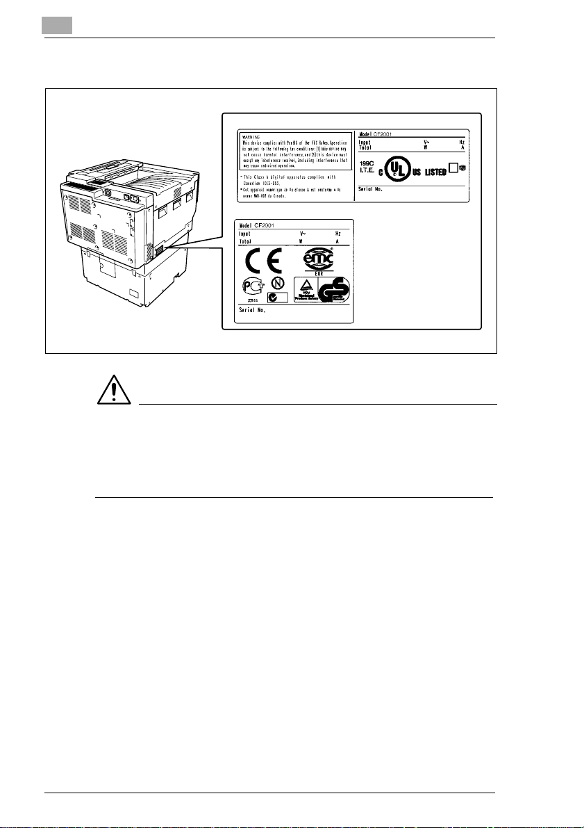
WARNING LABEL
US:
Europe:
CAUTION
Install this machine so that it can quickly be unplugged from the
electrical outlet in case of an emergency.
➜ The socket-outlet shall be installed near the machine and shall be
easily accessible.
LED Radiation Safety
This product is a printer which operatesby means of a LED (light emitting
diodes) exposure system. There is no possibility of danger from the LED
opticalradiation, because the LEDoptical radiationlevel does not exceed
the accessible radiation limit of class 1 under all conditions of operation,
maintenance, service and failure.
1-8 CF2001P
Page 14

Introduction
1.3 Guide to Manuals
Enclosed Manuals
In order to refer to the User Manual quickly when necessary, store it near
the printer.
User Manual
The User Manual describes the functions, operating procedures, precautions, and basic troubleshooting for this printer. Before using this
printer,be sure to read the User Manual thoroughlyin order to ensure
that the printer operates properly and is used efficiently.
Explanation of Manual Conventions
The marks and text formats used in this manual are described below.
WARNING
Failureto observeinstructionshighlightedin this manner may result
in fatal or critical injuries.
➜ Observe all warnings in order to ensure safe use of the printer.
1
CAUTION
Failureto observeinstructionshighlightedin this manner may result
in serious injuries or property damage.
➜ Observe all cautions in order to ensure safe use of the printer.
CF2001P 1-9
Page 15

1
Introduction
✎
Note
(*May also appear as “Important” or “Tip”)
Text highlightedin this manner contains useful informationand tips to
ensure safe use of the printer.
1 The number 1 as formatted here in-
dicates the first step of a sequence
of actions.
2 Subsequent numbers as formatted
hereindicate subsequentsteps of a
sequence of actions.
Text formatted in this style pro-
?
vides additional assistance.
➜ Text formattedin this style describes the action that will ensure the
desired results are achieved.
An illustration inserted here shows
what operations must be performed.
1-10 CF2001P
Page 16
Introduction
1.4 Explanation of Basic Concepts and S ymb ols
The use of words and symbols in this manual are explained below.
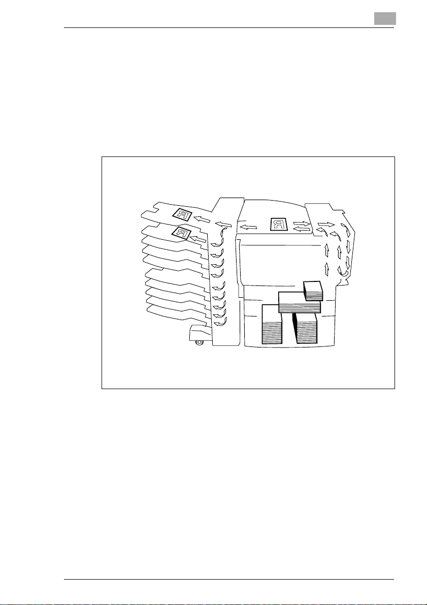
Paper Feeding
Duringprinting, paper is supplied from the right side of the printer and fed
into the output tray on top or the output option at the left with the printed
surfaceof thepage facing down. The paperfeed directionis shown by the
arrows in the diagram below.
1
CF2001P 1-11
Page 17
1
Introduction
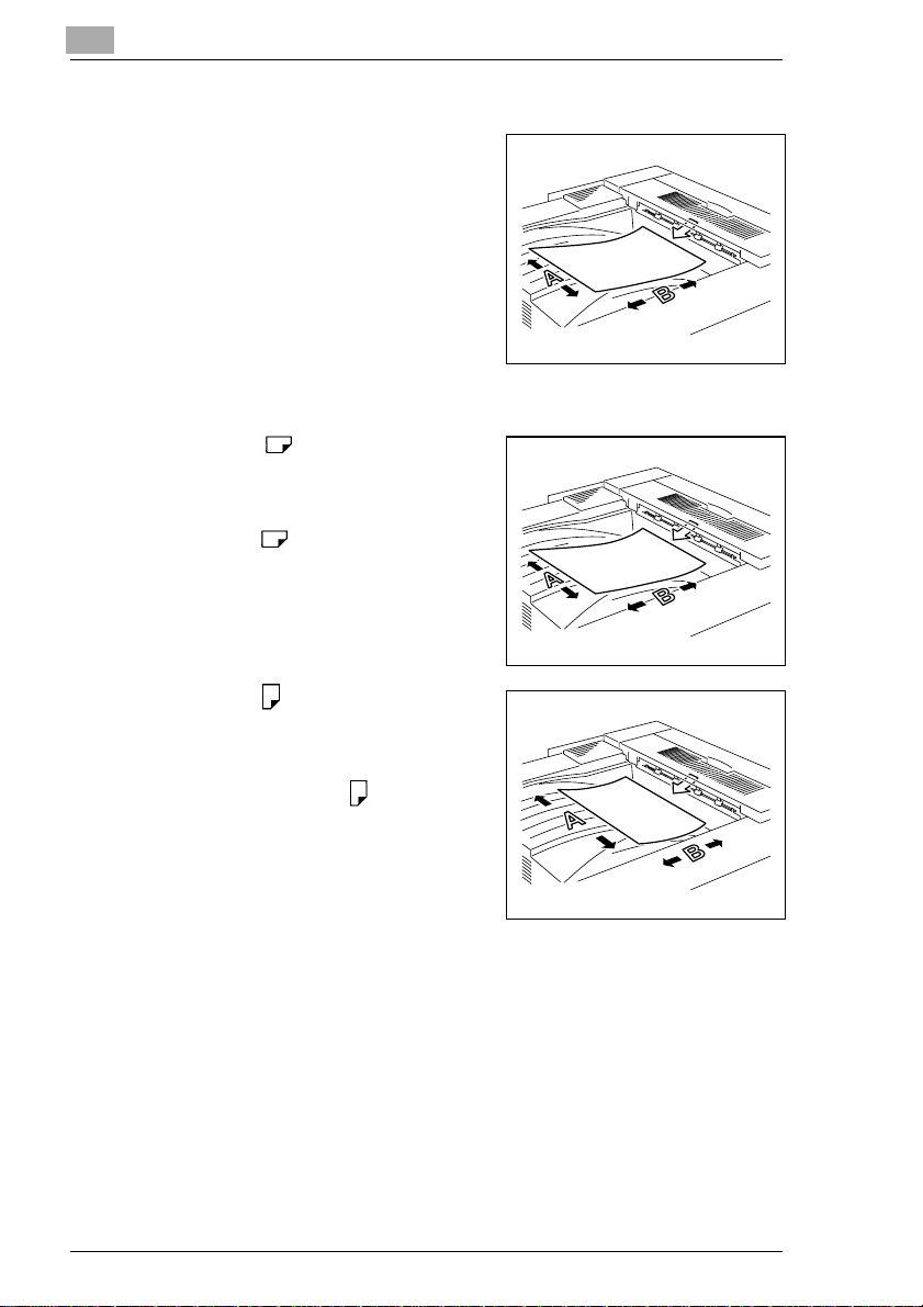
“Width” and “Length”
Whenever paper dimensions are mentioned in this manual, the first value always refers to the width of the paper
(shownas“A” inthe illustration) and the
second to the length (shown as “B”).
Paper Orientation
Lengthwise ( )
If the width (A) of the paper is shorter
thanthe length(B), the paper has a vertical or portrait orientation, indicated by
either “L” or .
Crosswise ( )
If the width (A) of the paper is longer
thanthe length(B), the paperhas a horizontal or landscape orientation, indicated by either “C” or .
1-12 CF2001P
Page 18

Introduction
1.5 Features
The MinoltaCF2001P is a high-speed, high-quality full-color printer, combining the functionality and compactness best suited for any office.
Delivers high-speed, high-quality full-color printouts
High-quality,business-standard images with a resolution of 600 dpi ×
600 dpi (simulated)/256 variations
High-speed full-color printing (Letter/A4 landscape/continuous printing) at 20 sheets per minute
Combines handling of a large paper capacity in a compact design:
Lightweight, space-saving full-color printer
Maximum paper capacity of 3,250 sheets (including optional paper
cassettes)
Can be combined with a wide variety of options:
10-mailbinsorter, paper feed unit,andduplexunit,etc., providing even
more features
1
CF2001P 1-13
Page 19

1
Introduction
1-14 CF2001P
Page 20

Precautions
2 Precautions
2.1 Installation Precaution s
Installation site
To ensure utmost safety and prevent possible malfunctions, install the
printer in a location that meets the following requirements.
- A location away from curtains, etc. that may catch fire and burn easily
- A location that is not exposed to water or other liquids
- A location free from direct sunlight
- A location out of the direct airflow of an air conditioner or heater, and
not exposed to extremely high or low temperatures
- A well-ventilated location
- A location that is not exposed to high humidity
- A location that is not extremely dusty
- A location not subjected to undue vibrations
- A stable and level location
- A location where ammonia or other organic gases are not generated
- A location that does not place the operator in the direct airflow of ex-
haust from the printer
- A location that is not near any kind of heating devices
2
Power source
The power source requirements are as follows.
Voltage fluctuation: Maximum ±10%
(AC 127 V areas only: between -10% and +6%)
Frequency fluctuation: Maximum ±0.3%
❍ Use a power source with as little voltage or frequency fluctuations as
possible.
CF2001P 2-1
Page 21
2
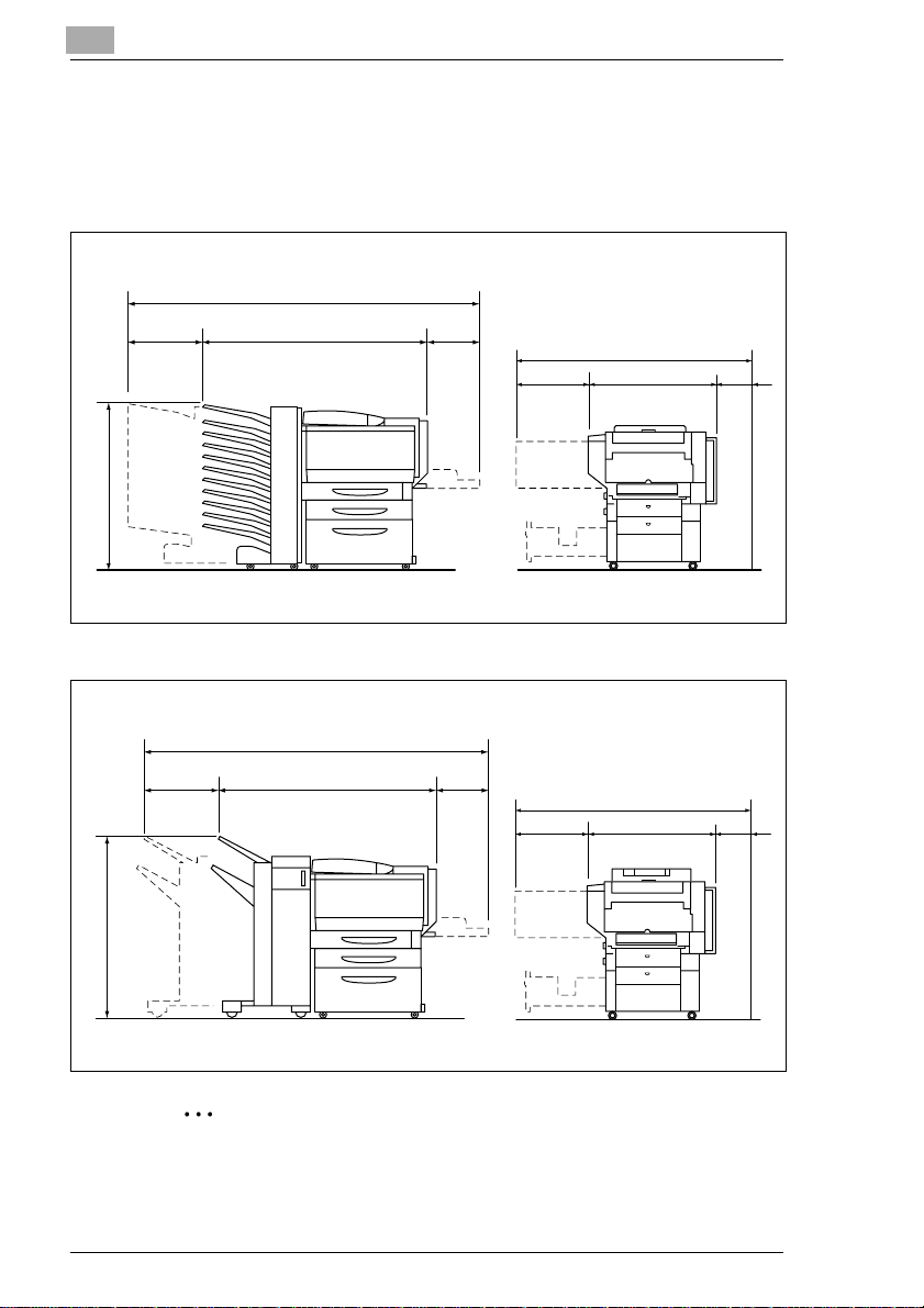
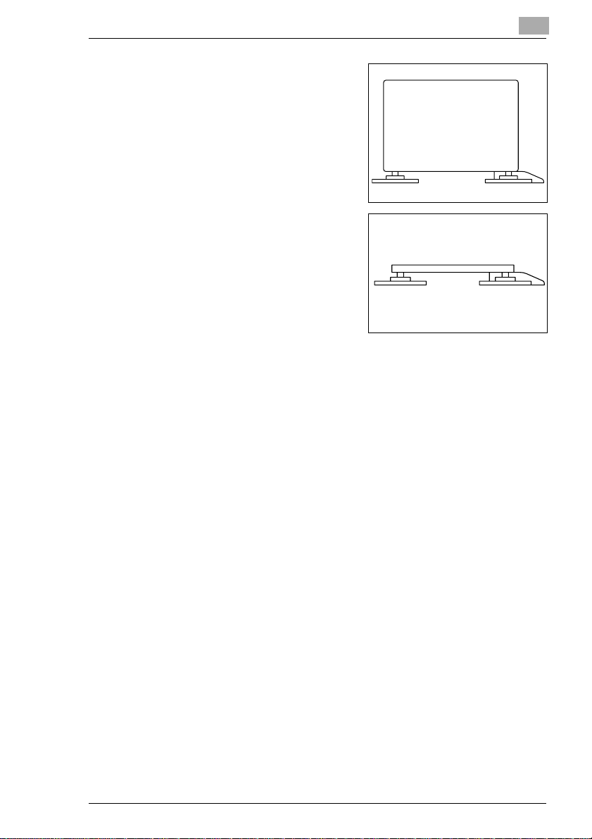
Space requirements
To ensure easy printer operation,supply replacement,and maintenance,
adhere to the recommended space requirements detailed below.
63.98 (1,625)
10.43 8.27
(265) (210)
34.41 (874)
45.28 (1,150)
20 (510)
55 (1,397)
31 (787)
Unit: inch (mm)
Precautions
4
(100)
62.17 (1,579)
9.25 8.27
(235) (210)
38.50 (978)
44.65 (1,134)
55 (1,397)
20 (510) 31 (787)
(100)
4
Unit: inch (mm)
✎
Note
Be sure to allow a clearance of 4 in. (100 mm) or more at the back of
the printer for the ventilation duct.
2-2 CF2001P
Page 22
Precautions
2.2 Operation Precautions
Operating environment
Theenvironmentalrequirementsfor correct operationofthe printerare as
follows.
Temperature:50°F(10°C) to 86°F(30°C) with fluctuations of no more
than 18°F(10°C) within an hour
Humidity:25% to 85% with fluctuations of no more than 20% withinan
hour
Proper use
To ensure the optimum performance of the printer, follow theprecautions
listed below.
- Never open any printer doors or turn off the printer while it is printing;
otherwise, a paper jam will occur.
- Neverbring any magnetized object or useflammable sprays or liquids
near the printer.
✚ Always make sure that the power plug is completely plugged into the
electrical outlet.
- Always make sure that the printer’s power plug is visible and not hid-
den by the printer.
✚ Always unplug the printer from the e lectrical outlet if the unit is not to
be used for a long period of time.
✚ Always provide good ventilation when making a large number of con-
tinuous prints.
2
CAUTION
A negligible amount of ozone is generated during normal operation
of this printer. An unpleasant odor may, however, be detected in
poorly ventilated rooms during extensive printer operations.
➜ For a comfortable operating environment, it is recommended that the
room be well ventilated.
CF2001P 2-3
Page 23

2
Precautions
CAUTION
If the ventilation duct at the top of the printer becomes blocked, the
inside of the printer will accumulate heat, resulting in a malfunction
or fire.
➜ Do not place any objects over the ventilation duct.
CAUTION
The area around the fusing unit is extremely hot.
➜ Be careful not to touch any parts around the fusing unit, other than
those indicatedin this manual, in order to reduce the risk of burns. Be
especially careful not to touch parts marked with warning labels, and
their surrounding areas.
➜ If you get burnt, immediately cool the skin under cold water, and then
seek professional medical advice.
Transporting the printer
If you need to transport the printer over a long distance, consult your service representative.
Care of printer supplies
Use the following precautions when handling the printer supplies (toner,
paper, etc.).
✚ Store the supplies in a location that meets the following requirements:
free from direct sunlight
away from any heating apparatus
not subjected to high humidity
not extremely dusty
✚ Store in a sealed plastic bag in a cool, dark place paperthat has been
removed from its wrapper but not loaded into the printer.
- Only use toner thathas beenmanufacturedspecificallyfor this printer.
Never use other types of toner.
- Keep all supplies out of the reach of children.
2-4 CF2001P
Page 24

Precautions
CAUTION
Precautions for handling toner:
➜ Be careful not to spill toner inside the printer or get toner on your
➜ If your hands become soiled with toner, immediately wash them with
➜ If tonergets in your eyes, immediatelyflush them with water,and then
2
clothes or hands.
soap and water.
seek professional medical advice.
CF2001P 2-5
Page 25

2
Precautions
2-6 CF2001P
Page 26
Before Making Prints
3 Before Making Prints
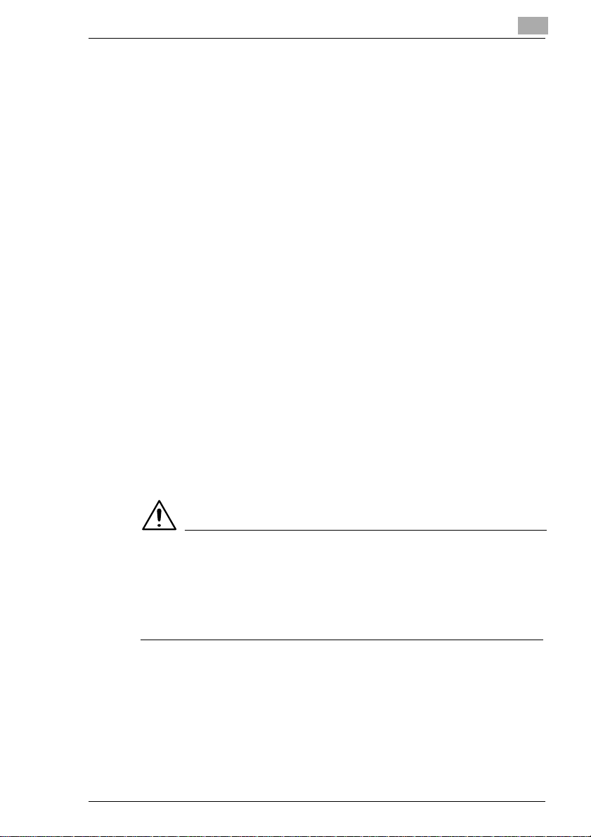
3.1 Components and Their Functions
The following describes each of the units that the printer is composed of
as well as their functions.
Printer
Prints out the image received from
the computer
10-MailbinsorterJS-1002 (optional)
Feeds pages into the mailbin specified at the computer
3
Note)
If Fiery X3e has been installed, the
10-mailbin sorter is not operational.
CF2001P 3-1
Page 27
3
Before Making Prints
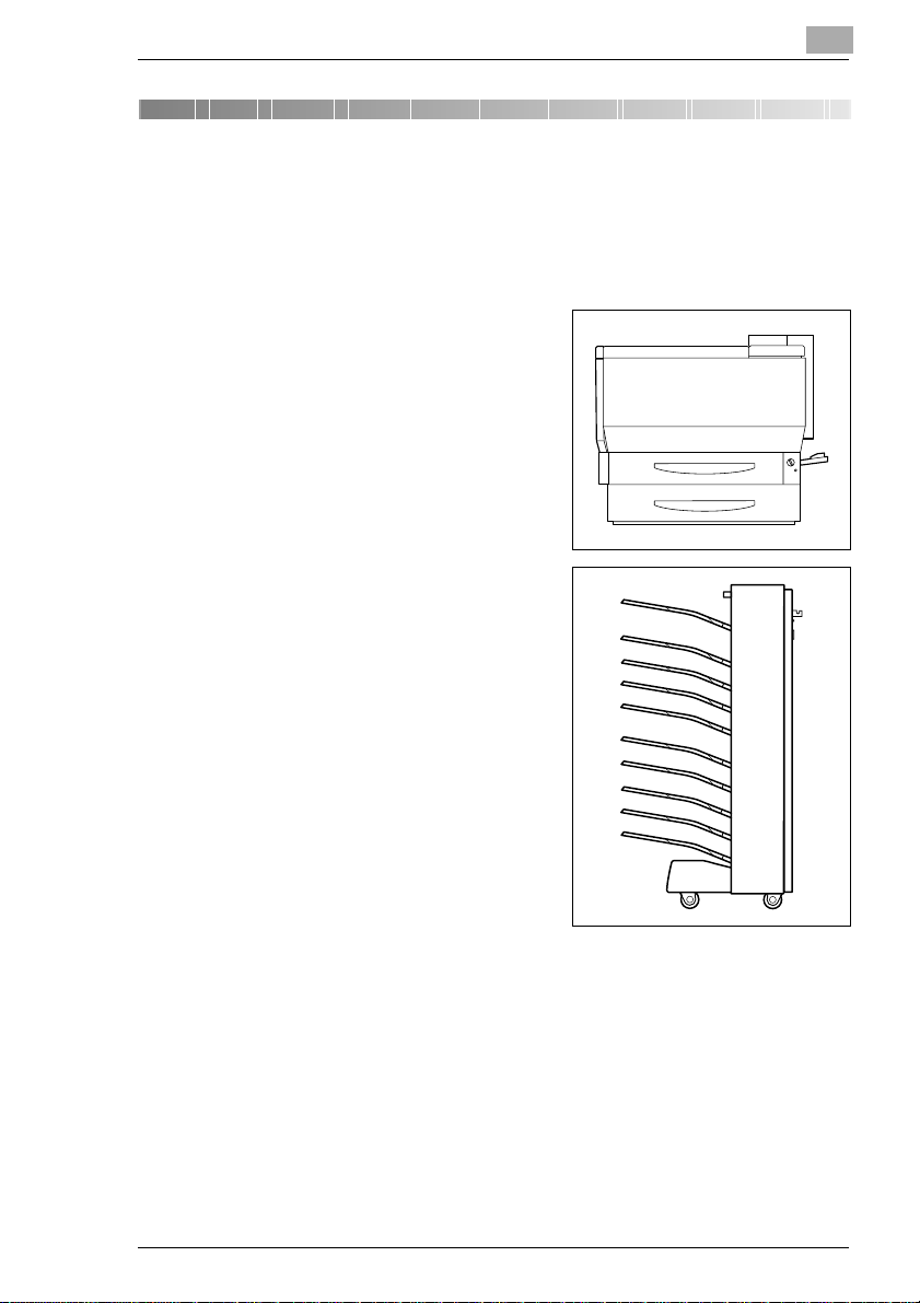
Finisher FN-107/FN-108 (optional)
finishes pages according to the
mode(electronicsorting,staplingor
hole-punching)selected at the computer, then feeds out the pages
Note)
If MicroPress PrintLink 2020m is installed, only FN107 is supported.
Duplex unit AD-14 (optional)
Automatically turns over prints, allowing double-sided prints to be
made
Paper feed unit PF-118 (optional)
Can supply 500 sheets of paper; up
to two paper feed units can be installed
Large-capacitycabinet PF-117 (op-
tional)
Can supply 2,500 sheets of paper
3-2 CF2001P
Page 28
Before Making Prints
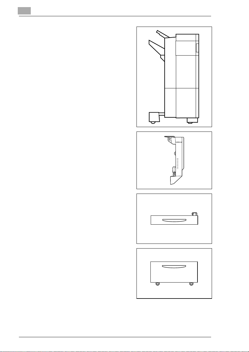
Copy desk (optional)
Used when the optional 10-mailbin
sorter (JS-1002) or an optional finisher (FN-107/FN-108) is installed
without an optional paper feed unit
Copy table (optional)
Used when the optional 10-mailbin
sorter (JS-1002) or an optional finisher (FN-107/FN-108) is installed
with two optional paper feed units
installed
Printer controller Fiery X3e
Internal printer controller that allows the printer to be used as a color
printer on a network
Printer controller M icroPress PrintLink 2020m
Internal printer controller that allows the printer to be used as a color
printer on a network
3
CF2001P 3-3
Page 29
3
3.2 Parts Names and Their Functions
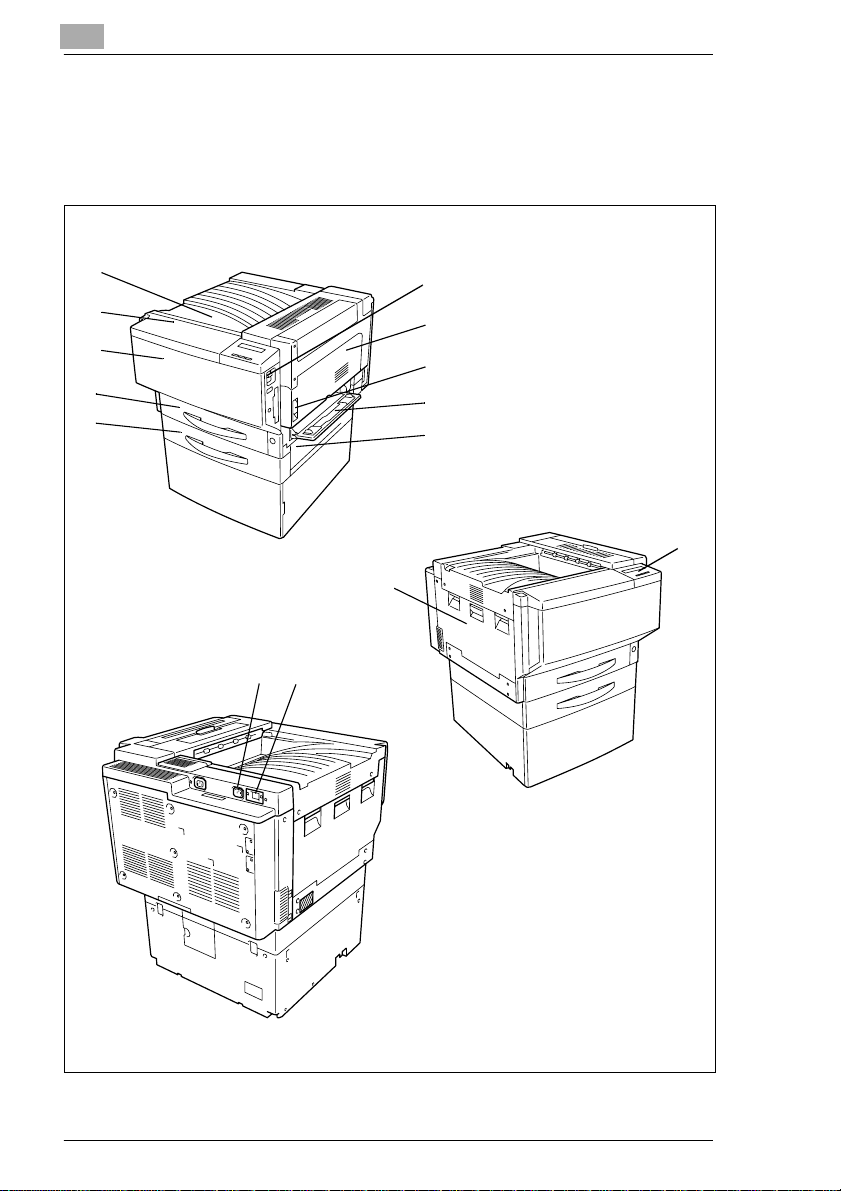
Outside of Printer
Before Making Prints
1
2
3
4
5
14
13
6
7
8
9
10
12
11
* The copy desk shown installed in the illustration is optional.
3-4 CF2001P
Page 30

Before Making Prints
No. Part Name Description
1 Printoutput tray Holds printoutsfed from the printer
2 Toner supply door Opened when adding toner
3 Frontdoor Opened when servicing the printer.
4 Tray 1 Holds 250 sheets of paper
5 Tray 2 Holds 500 sheets of paper
6 Powerswitch Used to turn the printeron and off
7 Right-side door Opened when servicing the printer and clearing misfeeds
8 Right-sidedoorrelease
lever
9 Manual bypasstray* Used for manual feeding of paper
10 Lowerright-side door Opened when clearing misfeeds
11 Left-side door Opened when servicing the printer
12 Control panel Displays the current status of the printer
13 Printer power cord
socket
14 Sorter/finisher connec-
tor
* When Fiery X3e is installed, printingfrom the manual bypass tray is not supported.
3
Thepapersizecanbeadjustedfreely.
Specialpapercanbeused.Seep.4-7.
Thepapersizecanbeadjustedfreely.Seep.4-12.
See p. 3-14.
Used to open and close the right-sidedoor
The paper is fed one sheet at a time
Used for connecting the printer’spowercord
Used for connectingthe sorter or finisher hookup cord
CF2001P 3-5
Page 31

3
Before Making Prints
Inside of Printer
1
2
3
No. Part Name Description
1 Toner hopper lid Opened when adding toner
2 Imagingunit releasele-
ver
3 Imagingunit removing
bracket
4 Upper right-side door Openedwhen replacingthe fusingunitor clearingmisfeeds
Used to install and replace the imaging unit
Used to remove the imaging unit
4
3-6 CF2001P
Page 32

Before Making Prints
Supplies and Parts
3
1
4
7
2
5
8
3
6
9
No. Part Name Description
1 Imaging unit Generates the printed image
2 Image transferbeltunit Layers onto the image transferbelt each of the single col-
3 Image transferroller
unit
4 Waste to ner bottle Collects waste toner
5 Oil-coating unit Supplies oil to the fusing roller
6 Fusing web unit Suppliesoil to the fusing belt
7 Fusing unit Fuses the transferred toner to the paper
8 Ozone filter Collectsthe ozonegenerated in the printer
9 LED cleaning tool Used to clean the surfaceof the LED unit, for example
ors of the image generatedby the imaging unit in orderto
create a full-colorimage
Transfersonto the paper a full-color image generatedby
the image transfer belt unit
when replacingthe imagingunit
Storeinasafeplaceforlateruse.
CF2001P 3-7
Page 33

3
Before Making Prints
Duplex Unit (Optional)
1
No. Part Name Description
1 Duplex unit door Opened when clearing paper misfed within the duplex unit
3-8 CF2001P
Page 34

Before Making Prints
10-Mailbin Sorter (Optional)
1
2
3
3, 4
No. Part Name Description
1 Mailbins Paper is fed to the mailbin specified with the printerdriver
2 Upper door/Lowerdoor Opened when clearingpaper misfed withinthe sorter
3 Horizontal transport
unit
4 Horizontal transport
unit cover
Transports prints to the sorter or finisher
Opened when clearingpaper misfed within the horizontal
transport unit
CF2001P 3-9
Page 35

3
Before Making Prints
Finisher (Optional)
2
3
4
5
No. Part Name Description
1 Upper cover Opened when clearing paper misfed withinthe finisher
2 Upper paper output
tray
3 Lower paper output
tray
4 Front door Opened when clearing paper misfed within the finisher
5 Right-side door
(Finisher FN-107 only)
1
Collects printoutson special paper. (overheadprojector
transparencies,thickpaper1,thick paper2, and postcards)
Collects printoutson normal paper.
Opened when replacing the staple cartridge or clearing paper misfeeds
3-10 CF2001P
Page 36

Before Making Prints
Paper Feed Unit (Optional)
No. Part Name Description
1 Side door Opened when clearing paper misfeeds
2 Tray 3 Holds 500 sheets of paper
3Tray4
2
3
The paper size can be adjusted freely.
As many as two units can be installed.See p. 4-12.
3
1
CF2001P 3-11
Page 37

3
Before Making Prints
Large-Capacity Cabinet (Optional)
No. Part Name Description
1 Side door Opened when clearing paper misfeeds
2 Large-Capacity
Cabinet
Holds 2,500 sheets of paper
See p. 4-14.
1
2
Printer Controller Fiery X3e
For more details, refer to the manual of the printer controller.
Printer Controller MicroPress PrintLink 2020m
For more details, refer to the manual of the printer controller.
3-12 CF2001P
Page 38

Before Making Prints
3.3 Names of Control Panel Parts and Their Functions
Names of Control Panel Parts and Their Functions
3
1
2
3
4
No. Part Name Description
1 Readylight • Off when the Fiery X3e is off or startingup
2 Display window • Displays information about the currentstatus
3 Up/downbuttons • Up button:Returns to the previous option or setting if
4 Right/left buttons • Right arrow: Advances the cursor to the next entry
5 Menu button • Displays the Functions menu; returns to the menu if
6 Set button • Activatesthecurrentlyselectedoptionand, ifapplicable,
7 Cancelbutton • Exits the setup and returns to Info; stops printing or
8 Messagelight • Lights up in red for m ore than 30 seconds to indicate a
Ready
Menu Set Cancel
567
• Lights up in green to indicate the normal operating
condition
• Flashes green when the Fiery X3e is proceedingto RIP
or printing a job, or communicating with a remote
computer.(for example, through the Fiery Spooler)
pressedwhen a menu is displayed;displays the
previous character if pressed when entering text
• Down button: Advances to the next option or setting if
pressedwhen a menu is displayed;displays the next
character if pressed when entering text
position on the right
• Left arrow: Deletes the character to the left if pressed
when entering text
pressedafteran option has been selected
proceeds to the next menu
processing the current job if pressed when printing
communication error between the Fiery X3e and the
printer
• Flashes red if there is an error that preventsprinting
Message
8
CF2001P 3-13
Page 39

3
3.4 Power Switch
Turning the printer on and off
To turn the printer on
➜ Set the power switch to “1”.
To turn the printer off
➜ Set the power switch to “2”.
✎
Note
Do not turn off the printerwhile it isprinting,otherwisea papermisfeed
may occur. Make sure that all print operations are finished before
turning off the printer.
Before Making Prints
✎
Note
With Fiery X3e installed, if the printer is turned off directly, instead of
turning off the system using the control panel, the controller may be
damaged.
✎
Note
If the printer is not used for 15 minutes, it automaticallyenters Energy
Saver mode.
The printer will automatically start warming up as soon as it receives
a print job, or when any cover is opened, then closed.
3-14 CF2001P
Page 40

Before Making Prints
Turning On the Printer
After the printer is turned on, the
controller is initialized. After the
controller has finished warming up, the
Ready light lights up in green and “Info
XXXX” appears in the display.
However, a print operation is not
performed until the printer has finished
warming up (after about 5 minutes at
normal room temperature (68 °F/20
°C)).
✎
Note
“XXXX” indicates the name specified when the controller was set up.
(For more details, refer to the m anual of the printer controller.)
Ready
Info
××××
Menu Set Cancel
3
Message
CF2001P 3-15
Page 41

3
Before Making Prints
Turning Off the Printer
✎
Note
If Fiery X3e is installed, be sure to shut down the controller system
before turning off the printer.
If MicroPress PrintLink 2020m is installed, turn off the printer by
performing just step 5.
To turn off the printer
1 Check that “Info XXXX” appears in
the display, and then press the
[Menu] button in the control panel.
2 Press or until “Functions Shut
Down”appears, and then press the
[Set] button.
Ready
Info
××××
Menu Set Cancel
Ready
Functions
Shut Down
Message
Message
Menu Set Cancel
3 Press once to display “Shut
Down Shut Down System”,and
then press the [Set] button to begin
shutting down the system.
3-16 CF2001P
Ready
Shut Down
Shut Down System
Menu Set Cancel
Message
Page 42

Before Making Prints
4 When the system has finished
shutting down, “Safe to power off
the system” appears.
5 Set the power switch to “2”.
Ready
Safe to power off
the system
Menu Set Cancel
3
Message
CF2001P 3-17
Page 43

3
3.5 Total Counter
The total counter can be printed out by following the procedure below.
To print the total counter
1 Check that “Info XXXX” appears in
the display, and then press the
[Menu] button in the control panel.
2 Press or until “Function Print
Pages”appears, and thenpress the
[Set] button.
Before Making Prints
Ready
Info
××××
Menu Set Cancel
Ready
Functions
Print Pages
Message
Message
Menu Set Cancel
3 Press or until“Functions Total
Counter” appears, and then press
the [Set] button.
3-18 CF2001P
Ready
Functions
Total Counter
Menu Set Cancel
Message
Page 44

Before Making Prints
4 The total counter is printed out.
(Refer to page 4-7 for Loading
Paper.)
Full Color Black
Copy
Large
Print
Large
G.Total
Serial #
Total Check
0
0
71
0
81
2001
3
6
16
29
26
Dup. Copy
0
0
0
Dup. Print
10
0
0
CF2001P 3-19
Page 45

3
Before Making Prints
3-20 CF2001P
Page 46

Print Paper
4 Print Paper
4.1 Paper Specificat ion s
Use paper that meets the following specifications.
Paper Types
4
2
)
SpecialPaper
Thick
Paper1
24. 21 lbs.
to 43.36
lbs.
(91 g/m2to
2
163 g/m
)
Thick
Paper2
43.62 lbs.
to 55.59
lbs.
(164 g/m
to 209 g/
2
m
)
2
Overhead
Projector
Transparencies
Postcards
Paper Types
Weight (lbs.)
Weight (g/m2)
Tray 1 22— 22
Tray 2 2 ————
Manual bypass
*1
tray
Paper Feed
*2
Unit
Large-Capacity
*2
Cabinet
* 1: When Fiery X3e is installed,printing from the manualbypasstrayis not supported.
2: The paper feed unit and large-capacity cabinet are optional.
Standard
Paper
17.02 lbs.
to 23.94
lbs.
(64 g/m2to
90 g/m
22222
2 ————
2 ————
CF2001P 4-1
Page 47

4
Print Paper
Paper Sizes
Standard paper:
Paper Size
Paper Source
Tray 1 22222 22
Tray 2 — 22222—
Manual bypass
*1
tray
Paper Feed
*2
Unit
Large-Capacity
*2
Cabinet
Paper Size
Paper Source
Tray 1 22222 22
Tray 2 —————22
Manual bypass
*1
tray
Paper Feed
*2
Unit
Large-Capacity
*2
Cabinet
12.25 ×
18L
2222222
— 22222—
—————2 —
ExecutiveC
2222222
—————22
———————
11 × 17L11 × 14
*3
5.5 ×
8.5L
L
5.5 ×
8.5C
LegalL LetterL LetterC
A3Wide
*3
4×6L
L
*4
A3L A4L
ExecutiveL
4-2 CF2001P
Page 48

Print Paper
4
Paper Size A4C A5L A5C A6L
Paper Source,
Etc.
Tray 1 2222
Tray 2 2 ———
Manual bypass
*1
tray
Paper Feed
*2
Unit
Large-Capacity
*2
Cabinet
* 1: When Fiery X3e is installed,printing from the manualbypasstrayis not supported.
2: The paper feed unit and large-capacity cabinet are optional.
3: For NorthAmerica only
4: For Europeonly
2222
2 ———
2 ———
*4
CF2001P 4-3
Page 49

4
Print Paper
Paper capacity:
Paper Type
Paper Source,
Etc.
Tray 1 250 sheets 20 sheets — 20 sheets 20 sheets
Tray 2 500 sheets ————
Manual bypass
*1
tray
Paper Feed Unit
Large-Capacity
*2
Cabinet
* 1: When Fiery X3e is installed,printing from the manual bypass tray is not supported.
2: The paper feed unit and large-capacity cabinet are optional.
Standard
Paper
1 sheet 1 sheet 1 sheet 1 sheet 1 sheet
*2
500 sheets ————
2,500
sheets
SpecialPaper
Overhead
Thick
Paper1
————
Thick
Paper2
Projector
Transpar-
encies
Postcards
Recommendedpaper:
Paper Type RecommendedPaper
StandardPaper For full-colorprints CF80
For black-and-w hite
prints
Thick Paper 1 CF105
Thick Paper 2 NS 1000C
OverheadPro-
jectorTransparencies
* 1: The paper is available for North America only.
2: The paper is available for Europe only.
For full-colorprints CF-300D
For black-and-w hite
prints
Hammermill Laser P rint New Radiant White
Color Copy 90
MINOLTA bond
MINOLTA bond IV
Original
NS 700
M-100D
*2
*1
*2
*1
*1
4-4 CF2001P
Page 50

Print Paper
Paper Types To Be Avoided
The following types of paper should not be used, otherwise decreased
print quality, paper misfeeds or damage to the printer may occur.
Overhead transparencies that have already been fed through the
Paper that has been printed on by a heat-transfer printer or an inkjet
Paper that is either extremely thick or extremely thin
Folded, rolled, wrinkled, or torn paper
Perforated paper or paper with holes punched in it
Extremelysmooth o r extremely rough paper,or paper with an uneven
Paper that has been treated, such as carbon-backed paper, or heat-
Paper that has been decorated with foil or embossing
Paper of various sizes
Paper of a non-standard shape (not rectangular)
Paper that is bound with glue, staples, or clips
Paper with labels attached
Paper with ribbons, hooks, buttons, etc. attached
4
printer (even if the transparency is still blank)
printer
surface
sensitive or pressure-sensitive paper
CF2001P 4-5
Page 51

4
4.2 Print Area
When using a printer controller to print from a computer, any part of the
original image within the areas indicated below is not printed.
The sizes of the paper margins differ according to the controller that is
used.
C
C
4.3 Paper Storage
Observe the following precautions when storing the paper.
✚ Store the paper in a location that meets the following requirements.
Not exposed to direct sunlight
Not exposed to fire
Not exposed to high humidity
Not extremely dusty
✚ Unwrappedpaper should be stored in a plastic bag in a cool, dry loca-
tion.
- K e ep paper out of the reach of children.
Print Paper
AB
Paper output direction
Fiery X3e MicroPressPrintLink 2020m
A: 0.2 in. (5mm) A: 0.2 in. (5 mm)
B: 0.2 in. (5 mm) B: 0.2 in. (5 mm)
C: 0.12 in. (3 mm) C: 0.2 in. (5 mm)
4-6 CF2001P
Page 52

Print Paper
4.4 Loading Paper
To load paper into Tray 1 (250-sheet multipurpose tray)
4
1 Pull out the paper drawer for Tray 1.
Has the paper take-up roller
?
been touched?
➜ Be careful not to touch the sur-
face of the paper take-up roller
withyour hands. Ifthe roller has
been touched, wipe it with a dry
cloth.
2 Press down on the paper-lifting
plate until it locks into place.
3 Slide the lateralguides to fit the size
of paper to be loaded.
Paper takeup roller
CF2001P 4-7
Page 53

4
Print Paper
❍ For “12-1/4 × 18” or A3Wide pa-
per, adjust the trailing-edge
guides as shown in the illustration.
4 Load the paper into the drawer so
that the front side of the paper (the
side facing up when the package
was unwrapped) faces up.
Has the paper been loaded cor-
?
rectly?
If the paper is not loaded correctly, a paper misfeed may occur.
➜ Do not load so much paper that the top of the stack is higher than
the Ä mark.
➜ Do not load more than 20 sheets of thick paper 1, overhead pro-
jector transparencies, or postcards.
➜ When loading additionalpaper, remove any paperremaininginthe
drawer, place it on the new paper, and then align the paper in the
stack well before loading it into the drawer.
➜ We recommend replenishing the paper only after all of the paper
in the drawer has been used.
4-8 CF2001P
Page 54

Print Paper
Are postcards loaded?
?
➜ When loading postcards, load
them as shown.
➜ Do not load postcards cross-
wise, as shown.
Are the recommended overhead projector transparencies (MI-
?
NOLTA CF300D) loaded?
➜ When loading the recommend-
ed overhead projector transparencies (MINOLTA CF300D),
load them as shown in the illustration.
4
CF2001P 4-9
Page 55

4
5 Slide the lateral guides against the
edges of the paper.
❍ Make sure that the paper is not
curled when it is loaded.
Checkthatthelateral guidesare
pushed up against the edges of
the paper.
6 Close the paper drawer.
7 Turn the media type selection dial
on the drawer to the setting for the
type of paper loaded.
Are postcards loaded into
?
Tray 1?
➜ If postcards (4 × 6orA6)are
loaded, the paper type setting
cannot be selected using the
media type selection dial on the drawer. Instead, use the control
panel buttons to select the paper size setting for postcards (4 × 6
or A6).
Print Paper
4-10 CF2001P
Page 56

Print Paper
To set the paper size for Tray 1
1 Check that “Info XXXX” appears in
2 Press or until “Engine Setup”
the display, and then press the
[Menu] button in the control panel.
appears, and then press the [Set]
button.
Ready
Info
××××
Menu Set Cancel
Ready
Functions
Engine Setup
Menu Set Cancel
4
Message
Message
3 Press or until the desired
paper size appears, and then press
the [Set] button.
Ready
1st Tr ay Setup
LETTER
Menu Set Cancel
Message
4 Press the [Cancel] button.
CF2001P 4-11
Page 57

4
To load paper into Tray 2 or the 500-sheet paper feed unit
1 Pull out the paper drawer.
Has the paper take-up roller
?
been touched?
➜ Be careful not to touch the sur-
face of the paper take-up roller
with your hands. If the roller has
been touched, wipe it with a dry
cloth.
2 Press down on the paper-lifting
plate until it locks into place.
3 Remove the trailing-edge guide,
and then re-install it for the size of
paper to be loaded.
Print Paper
Paper takeup roller
3
4
4 Slide the lateral guides tofit thesize
of paper to be loaded.
4-12 CF2001P
Page 58

Print Paper
5 Load the paper into the drawer so
6 Slide the lateral guides against the
that the front side of the paper (the
side facing up when the package
was unwrapped) faces up.
Has the paper been loaded cor-
?
rectly?
If the paper is not loaded correctly, a paper misfeed may o ccur.
➜ Do not load so much paper that the top of the stack is higher than
the Ä mark.
➜ Special paper cannot be fed from Tray 2 or optional paper feed
units.If you wishto make prints onto special paper, feed itthrough
Tray 1.
➜ Whenloadingadditionalpaper,removeanypaper remainingin the
drawer, place it on the new paper, and then align the paper in the
stack well before loading it into the drawer.
➜ We recommend replenishing the paper only after all of the paper
in the drawer has been used.
edges of the paper.
❍ Make sure that the paper is not
curled when it is loaded.
Check that the lateral guides are
pushed up against the edges of
the paper.
4
7 Close the paper drawer.
CF2001P 4-13
Page 59

4
Print Paper
To load paper into the large-capacity cabinet
1 Pull out the paper drawer.
2 Load paper into the right side of the
drawer so that the front side of the
paper (the side facing up when the
package was unwrapped) faces up.
Has the paper been loaded cor-
?
rectly?
If the paper is not loaded correctly, a paper misfeed may occur.
➜ Make sure that the paper is not curled when it is loaded.
➜ Do not load so much paper that the top of the stack is higher than
the Ä mark.
➜ Special paper cannot be fed from Tray 2 or optional paper feed
units. If you wish to make printsonto special paper, feed it through
Tray 1.
➜ When loading additionalpaper, remove any paperremaininginthe
drawer, place it on the new paper, and then align the paper in the
stack well before loading it into the drawer.
➜ We recommend replenishing the paper only after all of the paper
in the drawer has been used.
4-14 CF2001P
Page 60

Print Paper
3 Load paper into the left side of the
drawer so that the front side of the
paper (the side facing up when the
package was unwrapped) faces up.
Has the paper been loaded cor-
?
rectly?
If the paper is not loaded correctly, a paper misfeed may o ccur.
➜ Make sure that the paper is not curled when it is loaded.
➜ Do not load so much paper that the top of the stack is higher than
the Ä mark.
➜ Special paper cannot be fed from Tray 2 or optional paper feed
units.If you wishto make prints onto special paper, feed itthrough
Tray 1.
➜ Whenloadingadditionalpaper,removeanypaper remainingin the
drawer, place it on the new paper, and then align the paper in the
stack well before loading it into the drawer.
➜ We recommend replenishing the paper only after all of the paper
in the drawer has been used.
4
4 Close the paper drawer.
CF2001P 4-15
Page 61

4
Print Paper
To load paper into the manual bypass tray
Paper can be fed manually through the manual bypass tray if you wish to
print onto paper that is not loadedinto a draweror if you wish to print onto
specialpaper,suchasoverheadtransparencies,postcards,or thick paper
1or2.
Note
✔ When Fiery X3e is installed, printing from the manual bypass tray is
not supported.
1 Open the manual bypass tray.
2 Adjust the paper guides to the size
of the paper, and then load the paper so that the front side of the paper (the side facing up when the
package was unwrapped) faces
down. Lightly slide the paper into
thefeedslot as muchas possibleso
that it is ready to be fed into the
printer.
Do you need more information
?
on feeding paper through the manual bypass tray?
➜ Feed only one sheet of paper at a time.
➜ Prints will be made on the surface of the paper facing down when
it is loaded into the manual bypass tray.
4-16 CF2001P
Page 62

Print Paper
Is a postcard loaded?
?
➜ Whenloadinga postcard,loadit
as shown.
➜ Do not load the postcard cross-
wise, as shown.
Is the recommendedoverhead projector transparency (MINOLTA
?
CF300D) loaded?
➜ When loading the recommend-
ed overhead projector transparency (MINOLTA CF300D), load
it as shown in the illustration.
4
CF2001P 4-17
Page 63

4
Print Paper
4-18 CF2001P
Page 64

Control Panel Messages
5 Control Panel Messages
5.1 Message List
When a message appears inthe control panel display,refer tothe section
for details about the message and the action to be taken.
✎
Note
The display window only displays two lines of a message at one time.
To view messages longer than two lines, pressÄ to display the next
line of the message.
Message Cause Action
Busy The printeris printing. W ait for a while.
Check power of DT105 Power is not being supplied
Cover open at
xx
Image Stabilizing The printeris now image sta-
Load xx
xx in xx
Load xx
in xx
to the DT105.
The indicated cover is open. Press Ä once,check which
bilizing.
Paper of size xx and type xx
isnot loadedin the specified
tray.
Xx-sizepaper is not loaded
into the specified tray.
Check thatpower is supplied
to the DT105.
cover is open,andthenclose
it.
• Frontp.3-5,#3
• Right Side p. 3-5, #7
• Left Side p. 3-5, #11
• Fusing Unit p. 3-6, #4
• 2nd Feed p. 3-5, #10
• 3nd Feed p. 3-11, #1
• 4th Feed p. 3-11, #1
• LCC Feed p. 3-12, #1
• Duplex p. 3-8, #1
• Horizontal Transport
p. 3-9, #4
• Finisher Front p. 3-10,#4
• Finisher Upper p. 3-10, #1
• Sorter
Correctlyattach the sorter to
the printer.
• Finisher
Correctly attach the finisher
to the printer.
No action required.
Load paper of size xx and
type xx into the specified
tray.
Load xx-size paper into the
specified tray.
5
CF2001P 5-1
Page 65

5
Control Panel Messages
Message Cause Action
Load xx
OHP in tray1
Load xx
in any tray
Load xx
Thick 1 in tray1
Near trouble ## / ## Some malfunction occurred
No back staples The back staples have run
No front staples The frontstapleshave run
No xxxx toner
Call service
No xxxx toner
Please change
Paper jam at
Jx
Power save mode The printer has entered
Printing stopped Paperis loaded into the
Printing suspended Printing has been stopped. No action required.
Replace
Trans. Belt Unit
ServiceCode
Cxxxx
Sleep mode The printer has entered
Theguidesintray#
not set right
Xx-sizeoverhead projector
transparenciesis not loaded
into tray 1.
Xx-sizepaper has not been
loaded into any tray.
Xx-sizethick 1 is not loaded
into tray 1.
in the printer.
out.
out.
The toner for the indicated
coloris empty.
The toner for the indicated
coloris empty.
A paper jam or staple jam
occurredat the indicated
location.
Energy Saver mode.
manual bypass tray.
A communication error
occurred.
The service life of the
transferbelt unithas expired.
An error occurred. Contact your technical
Sleep mode.
The size of the paper loaded
into tray # is incorrect.
Load xx-size overhead projectortransparenciesinto
tray 1.
Load xx-size paper into any
tray.
Load xx-size thick1 into
tray 1.
Contactyourtechnicalrepresentative and informthem of
the error code.
Install new back staples.
Install new front staples.
Ask your technical
representative to refill the
tonerfor the indicated color.
Refill the toner for the indicated color.
Remove the jammed paper
orthejammedstaple.See
page 5-16
• To cancelEnergy Saver
mode,senda printjob, or
open and close a cover.
• To changethe timeforthe
printerto enter Energy
Saver mode, contacta
technical representative.
Remove all paper from the
manual bypass tray.
No action required
Replacethe transferbelt
unit.
representative and inform
them of the error code.
• To cancelSleep mode,
send a print job, or open
and close a cover.
• To changethe timeforthe
printerto enter Sleep
mode,contact a technical
representative.
Loadpaperofan appropriate
size into tray #.
5-2 CF2001P
Page 66

Control Panel Messages
Message Cause Action
To print,
clear 1st tray
To print,
clear elevatortray
To print,
clear mail bin #
To print,
clear sorterarea
Warming up Warming up No action required.
Waste toner full.
Call service
Waste toner full.
Please change
Waste toner
nearly full
Waste toner bottle
not set
Xxxx toner
nearly empty
Xxxx unit
near life limit
Xxxx unit
not set
Xxxx unit
not set right
Xxxx unit
over life limit
Call service
Xxxx unit
over life limit
Please change
The upper paper output tray
of the finisher is full of paper.
The lower paper output tray
of the finisher is full of paper.
Themailbin#ofthe10mailbin sorter is full of paper.
All bins in the 10-mailbin
sorter are full of paper.
The waste toner bottle is full. Ask your technical
The waste toner bottle is full. Replace the waste toner
The waste toner bottle will
soon be full.
The waste toner bottle is not
installed.
The toner for the indicated
color will soon be empty.
The indicatedunit willsoon
reachthe end of its service
life.
The indicatedunit is not
installed.
The indicatedunit is not
installed correctly.
The servicelife for the
indicated unit has expired.
The servicelife for the
indicated unit has expired.
Remove paper from the
upper paper output tray.
Remove paper from the
lower paper output tray.
Removepaper from the mail
bin #.
Remove all paper from the
mailbins.
representative to refill the
tonerfor the indicated color.
bottle.
Replacethe waste toner
bottleas soon as possible.
Installthe waste toner bottle.
Refill the toner for the
indicated color.
Replacethe indicatedunit.
Installthe indicated unit.
Installthe indicated unit
correctly or contact your
technical representative.
Ask your technical
representativeto replace the
indicated unit.
Replacethe indicatedunit.
5
CF2001P 5-3
Page 67

5
Control Panel Messages
To load paper into Tray 1 (250-sheet multipurpose paper drawer)
1 Pull out the paper drawer.
Has the paper take-up roller
?
been touched?
➜ Be careful not to touch the sur-
face of the paper take-up roller
with your hands. If the roller has
been touched, wipe it with a dry
cloth.
2 Press down on the paper-lifting
plate until it locks into place.
3 Load the paper into the drawer so
that the front side of the paper (the
side facing up when the package
was unwrapped) faces up.
Have you loaded too much pa-
?
per into the drawer?
➜ Do not load so much paper that
the top of the stack is higher
than the Ä mark.
Has the paper been loaded correctly?
?
➜ Make sure to align the stack of paper.
Do you wish to load a paper size or type different from that previ-
?
ously loaded?
➜ For more details on changing the paper size and type, refer to
“Loading Paper” on page 4-7.
Paper takeup roller
5-4 CF2001P
Page 68

Control Panel Messages
4 Slide the lateral guides against the
edges of the paper.
❍ Make sure that the paper is not
curled when it is loaded.
Check that the lateral guides are
pushed up against the edges of
the paper.
5 Close the paper drawer.
To load paper into Tray 2 or the 500-sheet paper feed unit
5
1 Pull out the paper drawer.
Has the paper take-up roller
?
been touched?
➜ Be careful not to touch the sur-
face of the paper take-up roller
withyour hands. Ifthe roller has
been touched, wipe it with a dry
cloth.
Paper takeup roller
2 Press down on the paper-lifting
plate until it locks into place.
CF2001P 5-5
Page 69

5
Control Panel Messages
3 Load the paper into the drawer so
that the front side of the paper (the
side facing up when the package
was unwrapped) faces up.
Have you loaded too much pa-
?
per into the drawer?
➜ Do not load so much paper that
the top of the stack is higher
than the Ä mark.
Has the paper been loaded correctly?
?
➜ Make sure to align the stack of paper.
Do you wish to load a paper size or type different from that previ-
?
ously loaded?
➜ For more details on changing the paper size and type, refer to
“Loading Paper” on page 4-7.
4 Slide the lateral guides against the
edges of the paper.
❍ Make sure that the paper is not
curled when it is loaded.
Checkthatthelateral guidesare
pushed up against the edges of
the paper.
5 Close the paper drawer.
5-6 CF2001P
Page 70

Control Panel Messages
To load paper into the large-capacity cabinet
1 Pull out the paper drawer.
2 Load paper into the right side of the
drawer so that the front side of the
paper (the side facing up when the
package was unwrapped) faces up.
Have you loaded too much pa-
?
per into the drawer?
➜ Do not load so much paper that
the top of the stack is higher
than the Ä mark.
3 Load paper into the left side of the
drawer so that the front side of the
paper (the side facing up when the
package was unwrapped) faces up.
Have you loaded too much pa-
?
per into the drawer?
➜ Do not load so much paper that
the top of the stack is higher
than the Ä mark.
5
4 Close the paper drawer.
CF2001P 5-7
Page 71

5
Control Panel Messages
5.2 When the Message “Xxxx toner nearly empty” Appears
✎
Note
Do not refill the toner until the message indicating that “Xxxx toner
nearly empty” appears on the control panel display.In addition,do not
refillthe tonerof any colorother than the one indicatedin themessage
on the control panel.
CAUTION
Be careful not to spill toner inside the printer or get toner on your
clothes or hands.
➜ If toner gets on your hands, wash them using water and a neutral
soap.
➜ If toner gets in your eyes, immediately rinse them, and then consult a
medical professional.
CAUTION
Precaution for the disposal of the used toner bottle
➜ Do not throw away the used toner bottle; instead, keep it to be collect-
ed by your technical representative.
WARNING
Precautions for handling toner and the toner bottle:
➜ Do not throw toner or the toner bottle into a fire. Toner expelled from
the fire may cause burns.
5-8 CF2001P
Page 72

Control Panel Messages
To add toner
1 Open the toner supply door, and
then open the toner hopper lid for
the toner that you wish to refill.
❍ For example: If the yellow toner
is empty, open the leftmost toner hopper lid.
2 With the opening of the new toner
bottle pointing up, hit the bottom of
the bottle against a strong surface,
such as a desk or table, four or five
timesfrom aheightofabout4in. (10
cm). (Since the toner within the
bottle may have become
compacted,be suretobreakitup by
performing this step.)
Is the toner bottle being held
?
correctly?
➜ When hitting the toner bottle
against a surface, be sure to
hold the bottle so that the opening of the bottle is pointing up.
5
3 While firmly grasping the new toner
bottle, shake it well.
Is the toner within the bottle
?
hard?
➜ The toner within the bottle may
become compacted. If it does,
be sure to shake the bottle until
thetoner is mostlybroken up before adding it to the hopper.
CF2001P 5-9
Page 73

5
Control Panel Messages
4 With the rounded side (marked with
“▼”) of the bottle mouth facing to-
wards you, place the toner bottle on
top of the hopper, and then press
down on the bottle until it snaps into
place.
5 Fully pull the toner hopper shutter
out toward you.
Pulling out the toner hopper shutter
allows the toner to fill the toner hopper.
Check that all of the toner has emptied out of the toner bottle and into
the hopper, which may take a while.
Do you know what precautions should be taken when refilling the
?
toner?
➜ Do not tap on the toner bottle
while refilling the hopper;
otherwise, the toner may spurt
out.
6 Push the toner hopper shutter
closed.
5-10 CF2001P
Page 74

Control Panel Messages
7 Tilt the toner bottle backward, and
thenpulltheopeningofthebottleup
and toward you to remove it.
8 Close thetoner hopper lid,and then
close the toner supply door.
5
CF2001P 5-11
Page 75

5
Control Panel Messages
5.3 When the Message “No xxxx staples” Appears
✎
Note
Be sure to replace the staple cartridge only after the message “No
xxxx staples” appears. Injuries may occur if the staple cartridge is removed before the message appears.
To replace the staple cartridge
1 Slide the finisher away from the
printer.
2 If finisher FN-107 is installed, open
right-side door FN7.
3 Turn the dial to the left in order to
position the stapler at the center.
5-12 CF2001P
Page 76

Control Panel Messages
4 Pull the staple holder out toward you.
❍ Finisher FN-107
❍ Finisher FN-108
Since finisher FN-107 is equipped with two staple holders, which
?
staple holder should be pulled out?
➜ The message on the control panel indicates which staple holder
should be pulled out.
5
Back Staple
Front Staple
Back Staple
5 (Finisher FN-107)
Remove the empty staple cartridge
from the staple holder.
2
1
CF2001P 5-13
1
3
Page 77

5
Control Panel Messages
6 (Finisher FN-107)
Insert the new staple cartridge into
the staple holder, andthen carefully
remove the stopper.
1
2
3
7 (Finisher FN-108)
Remove the empty staple cartridge
from the staple holder.
8 (Finisher FN-108)
Insert the new staple cartridge into
the staple holder, andthen carefully
remove the stopper.
2
5-14 CF2001P
1
Page 78

Control Panel Messages
9 Insert the refilled staple holder until it locks into place.
❍ Finisher FN-107
❍ Finisher FN-108
10If finisher FN-107 is installed, close
right-side door FN7.
5
11Slide the finisher back against the
printer.
CF2001P 5-15
Page 79

5
Control Panel Messages
5.4 Clearing a Paper Misfeed and Staple Jam
If a paper misfeed or a staple jam occurs during printing, the message
shown below appears.
Ready
Alert
Paper jam at
Menu Set Cancel
Message
Press ▼once and check where the paper misfeed occurred.
Ready
J×
Menu Set Cancel
Message
Follow the procedure below to clear the misfed paper or the jammed
staples.
5-16 CF2001P
Page 80

Control Panel Messages
5
JI
JH
JF
JG
JE
JA
JB
JC
JI
JH
JF
JG
JE
JA
JB
JC
JD
JJ
JL
JL
JJ
JK
JI
JH
JF
JG
JE
JA
JB
JC
JI
JH
JF
JG
JE
JA
JB
JC
JL
JJ
JL
JJ
JK
JI
JH
JF
JG
JE
JA
JB
JC
JD
JI
JH
JF
JG
JE
JA
JB
JC
JD
Message Description Message Description
JA Paper drawers p. 5-21 JB Paper drawers p. 5-21
JC Paperdrawers p. 5-21 JD Paper drawers p. 5-21
JE Manual bypass tray p. 5-18 JF Duplex unit p. 5-20
JG Printer p. 5-23 JH Printer p. 5-23
JI Printer p. 5-23 JJ Finisher FN-107/FN108 p. 5-26
JK FinisherFN-107/FN108 p. 5-26
10-mailbin sorter p. 5-30
JL Finisher FN-107/FN108p. 5-26
10-mailbin sorter p. 5-30
10-mailbin sorter p. 5-30
CF2001P 5-17
Page 81

5
Control Panel Messages
To clear a paper misfeed in the manual bypass tray
CAUTION
Decreased print quality may result if the surface of the image trans-
fer belt at the bottom of the printer’s fusing unit is touched.
➜ Be careful not to touch the surface
of the image transfer belt at the bottom of the printer’s fusing unit.
1 Pull up the lock release lever to
open the right-side door.
2 Carefully pull out the paper.
5-18 CF2001P
Page 82

Control Panel Messages
3 Close the right-side door.
5
CF2001P 5-19
Page 83

5
Control Panel Messages
To clear a paper misfeed in the duplex unit
1 Open the duplex unit door.
2 Carefully pull out the paper.
3 Close the duplex unit door.
5-20 CF2001P
Page 84

Control Panel Messages
To clear a paper misfeed in the paper feed unit
1 Open the lower right-side door.
2 Turn the green wheels to feed the
paper so that it can be easily removed.
3 Carefully pull out the paper.
5
Is the large-capacity cabinet installed?
?
➜ While turning the green dial in
the direction of the arrow, carefully pull out the paper.
CF2001P 5-21
Page 85

5
4 Close the lower right-side door.
5 Pull out the paper drawer being
used, and then remove any paper
remaining in the drawer.
6 Load the paper in the drawer again,
and then close the drawer.
Has the paper take-up roller
?
been touched?
➜ Be careful not to touch the sur-
face of the paper take-up roller
with your hands. If the roller has
been touched, wipe it with a dry
cloth.
Control Panel Messages
Paper take-up roller
5-22 CF2001P
Page 86

Control Panel Messages
To clear a paper misfeed in the printer
CAUTION
Decreased print quality m ay result if the surface of the image trans-
fer belt at the bottom of the printer’s fusing unit is touched.
➜ Be careful not to touch the surface
of the image transfer belt at the bottom of the printer’s fusing unit.
CAUTION
The area around the fusing unit is extremely hot.
➜ Touchinganything other than the paper within the area aroundthe fus-
ing unit may result in burns.
➜ If you get burnt, immediately cool the skin under cold water, and then
seek professional medical advice.
5
1 Pull up the lock release lever to
open the right-side door.
CF2001P 5-23
Page 87

5
2 Grasp the upper right-side door as
shown, and then carefully open the
door completely while making sure
to support it.
Is the upper right-side door be-
?
ing opened correctly?
➜ Be sure to support the door
while carefully opening it; otherwise, it may be damaged.
3 Whilemoving the greenleveron the
insideof the upperright-side door in
the direction of the arrow, carefully
pull out the paper.
4 Carefully pull out the paper.
Control Panel Messages
5 Move the two lock releaseleversfor
theoil-coatingunit in thedirectionof
the arrows.
5-24 CF2001P
Page 88

Control Panel Messages
6 Move the levers (one on each end
of the oil-coating unit) in the direction of the arrows and carefully pull
out the paper.
7 While holdingthelevers on theends
of the oil-coating unit, move the unit
back to its original position.
8 Fully move the two lock release le-
vers for the oil-coating unit in the direction of the arrows.
5
9 Close the upper right-side door.
10Close the right-side door.
CAUTION
The area around the fusing unit is extremely hot.
➜ Touching anything other than the indicated levers around the fusing
unit may result in burns.
➜ If you get burnt, immediately cool the skin under cold water, and then
seek professional medical advice.
CF2001P 5-25
Page 89

5
Control Panel Messages
To clear a paper misfeed in finisher FN-107/FN-108
CAUTION
Metallicparts inside MisfeedClearing Guide [FN1] are very hot. (Part
indicated in Step 10.)
➜ Do not touch anything but the paper to prevent you from getting
burned.
1 Slide the finisher away from the
printer.
2 Open the cover of the horizontal
transport unit.
5-26 CF2001P
Page 90

Control Panel Messages
3 Remove any paper, and then close
the cover of the horizontal transport
unit.
4 If finisher FN-107 is installed, open
right-side door FN7.
5
5 While holding open misfeed clear-
ing guide FN8 (for finisher FN-107)
or FN7 (for finisher FN-108), remove any paper.
CF2001P 5-27
Page 91

5
Control Panel Messages
6 If finisher FN-107 is installed, close right-side door FN7.
7 Open front door FN4.
8 Turn knobs FN5 at the same time to
feed out any paper.
9 Close front door FN4.
10Open upper cover FN1.
11While holding misfeed clearing
guide FN2 open,remove anypaper.
5-28 CF2001P
Page 92

Control Panel Messages
12While holding misfeed clearing
guideFN3 open,remove any paper.
13Close upper cover FN1.
14While holding misfeed clearing
guideFN6 open,remove any paper.
15Slide the finisher back against the
printer.
5
✎
Note
Be careful about a protrusion on the backside of the horizontal
transport unit cover.
Itcanhurtyou!(PartindicatedinStep3.)
CF2001P 5-29
Page 93

5
Control Panel Messages
To clear a paper misfeed in the 10-mailbin sorter
1 Slide the 10-mailbin sorter away
from the printer.
2 Remove any paper from the mail-
bins.
3 Open the cover of the horizontal
transport unit.
5-30 CF2001P
Page 94

Control Panel Messages
4 Remove any paper, and then close
the cover of the horizontal transport
unit.
5 Open the upper door and the lower
door.
5
CF2001P 5-31
Page 95

5
Control Panel Messages
6 Remove any paper.
7 Close the upper door and the lower door.
8 Slide the 10-mailbin sorter back
against the printer.
✎
Note
Be careful about a protrusion on the backside of the horizontal
transport unit cover.
It can hurt you! (Part indicated in Step 4.)
5-32 CF2001P
Page 96

Control Panel Messages
To clear jammed staples
1 Slide the finisher away from the
printer.
2 If finisher FN-107 is installed, open
right-side door FN7.
5
3 Turnthedialtotheleftinorderto
position the stapler at the center.
CF2001P 5-33
Page 97

5
4 Pull the staple holder out toward you.
❍ Finisher FN-107
❍ Finisher FN-108
Since finisher FN-107 is
?
equipped with two staple holders, which staple holder should
be pulled out?
➜ The message on the control
panel indicates which staple
holder should be pulled out.
5 Push the staple holder guide up,
and then pull out one sheet of staples.
Control Panel Messages
Back Staple
Front Staple
Back Staple
6 Move the guide back to its original
position.
5-34 CF2001P
Page 98

Control Panel Messages
7 Insert the staple holder until it locks into place.
❍ Finisher FN-107
❍ Finisher FN-108
8 If finisher FN-107 is installed, close
right-side door FN7.
5
9 Slide the finisher back against the
printer.
Are the staples still jammed,
?
evenafter performing the above
procedure?
➜ Contact a qualified technical
representative.
CF2001P 5-35
Page 99

5
Control Panel Messages
5.5 When the Message “Service Code Cxxxx” Appears
When the message shown below appears in the control panel display, a
malfunction has occurred within this printer.
Ready
Alert
Service Code
Menu Set Cancel
Message
Press ▼once and check which error code is displayed.
Ready
C××××
Menu Set Cancel
Message
If this messageappears, contact your technical representativeand inform
them of the error code that is indicated.
5-36 CF2001P
Page 100

Control Panel Messages
5.6 When the Message “xxxx unit near life limit” Appears
When it is almost time to replace a unit within this printer, a message like
the one shown below appears in the control panel.
When the message appears, replace the unit according to your maintenance agreement.
✎
Note
The display window only displays two lines of a message at one time.
Ä
To view messages longer than two lines, press
line of the message.
to display the next
5
Ready
Alert
×××× unit
Menu Set Cancel
Message
Ready
near life limit
Menu Set Cancel
Message
Displayed Messages
Advance warning message
When it is almost time to replace a unit, the message “xxxx unit near
life limit” appears in the control panel.
Prepare the new unit and replace it as soon as possible.
Replacement warning message
After the advance warning message has appeared, about 1,000 printouts can be made before the printer stops operating. (The number of
printouts d epends on the selected print settings and the unit.) In addition, the message “xxxx unit over life limit xxxx” appearsin the control
panel followed by instructions for replacing the unit.
Replace the unit according to the instructions that appear.
✎
Disposing of Used Parts
Dispose of used units according to your local regulations, or contact
your technical representative.
CF2001P 5-37
 Loading...