

Page 1
Page 2

Page 3

Contents
1 Introduction
CMS ............................................................................................... 1-3
Notices to the customer who employs the CMS ........................... 1-3
Registered trademark .................................................................... 1-3
1.1 Safety instructions............................................................................ 1-4
Warning and precaution symbols .................................................. 1-4
Meaning of symbols....................................................................... 1-4
Operations before replacing any part ............................................ 1-5
CMS part replacement operation................................................... 1-5
Power plug ..................................................................................... 1-6
When any abnormal condition is found ......................................... 1-7
1.2 Caution notations and caution labels ............................................. 1-8
2 bizhub PRO C6500/bizhub PRO C6500e
2.1 Maintenance procedure of the housing section............................ 2-3
Removing the dust-proof filter 1 assy............................................ 2-3
Reinstalling the dust-proof filter 1 assy ......................................... 2-4
Removing the dust-proof filter 2 assy............................................ 2-5
Reinstalling the dust-proof filter 2 assy ......................................... 2-6
2.2 Maintenance procedure of the toner collection box..................... 2-7
Removing the toner collection box assy........................................ 2-7
Reinstalling the toner collection box assy ..................................... 2-9
2.3 Maintenance procedure of the paper feeding section................ 2-10
Removing the pick-up roller/paper feed roller rubber.................. 2-10
Reinstalling the pick-up roller/paper feed roller rubber ............... 2-14
Removing the separation roller rubber ........................................ 2-15
Reinstalling the separation roller rubber ...................................... 2-16
2.4 Maintenance procedure of the bypass feed tray section ........... 2-17
Removing the pick-up roller/paper feed roller rubber.................. 2-17
Reintalling the pick-up roller/paper feed roller rubber ................. 2-21
2.5 Maintenance procedure of the fusing section ............................. 2-22
Removing the fusing unit ............................................................. 2-22
Reinstalling the fusing unit ........................................................... 2-26
bizhub PRO C6500 / bizhub PRO C6500e Contents-1
Page 4

3 PF-601/HT504
3.1 Maintenance procedure of the tray section.................................... 3-3
Removing the pick-up rubber/paper feed roller ............................. 3-3
Reinstalling the pick-up rubber/paper feed roller......................... 3-10
Removing separation roller........................................................... 3-11
Reinstalling the separation roller................................................... 3-16
4DF-609
4.1 Maintenance procedure of the paper feeding section................... 4-3
Removing the paper feed unit ........................................................ 4-3
Reinstalling the paper feed unit ...................................................... 4-6
Removing the pick-up roller/paper feed roller................................ 4-7
Reinstalling the pick-up roller/paper feed roller............................ 4-11
Removing the separation roller..................................................... 4-12
Reinstalling the pick-up roller/paper feed roller............................ 4-14
Cleaning the timing sensor (PS302).............................................. 4-15
Removing the registration roller cover.......................................... 4-17
Reinstalling the registration roller cover........................................ 4-18
Cleaning the registration roller...................................................... 4-19
Cleaning the registration sensor (PS301)...................................... 4-21
5 Appendix
5.1 Replacement parts list ...................................................................... 5-3
Main body ....................................................................................... 5-3
Paper feeding unit PF-601.............................................................. 5-4
Document feeder DF-609 ............................................................... 5-4
Contents-2 bizhub PRO C6500 / bizhub PRO C6500e
Page 5

1
Introduction
Page 6

Page 7

Introduction
1 Introduction
CMS
The CMS (Customer Maintenance Support) is a system that supports the
customer who conducts a parts replacement operation by himself without
getting an technical assistance from the customer engineer, to minimize the
downtime (shutdown period of the machine operation) of the machine of the
customer.
Notices to the customer who employs the CMS
When you want to employ the CMS, be sure to follow the instructions given
by the customer engineer.
And also, when you conduct a part replacement operation, be sure to read
each replacement instruction and follow the specific instructions given in it.
For your safety while in the replacement operation, be sure to keep this CMS
Instructions for Replacement safely, and also be careful not to get it lost.
Should it get lost, contact our service representative.
Registered trademark
bizhub PRO is a registered trademark of KONICA MINOLTA BUSINESS
TECHNOLOGIES, INC.
Copyright © 2006 KONICA MINOLTA BUSINESS TECHNOLOGIES, INC.
1
bizhub PRO C6500 / bizhub PRO C6500e 1-3
Page 8
1
1.1 Safety instructions
For your safe operation, the following are the descriptions of the notices and
requests that you have to follow when replacing parts. Be sure to read them
carefully before conducting any part replacement operation.
- Be sure to keep this CMS Replacement Instructions not to get it lost.
- Be sure to follow the caution items given in the CMS Replacement
Instructions.
Warning and precaution symbols
In this CMS Replacement Instructions and on the copier, various types of
graphic expressions are employed to allow you to conduct a part
replacement operation properly without causing harm to you as well as other
people, and also damage to the property.
The following indicators are used on the warning labels or in this manual to
categorize the level of safety warnings.
7 WARNING
Ignoring this warnings could cause serious injury or even death.
% Do not ignore these safety advices.
Introduction
7 CAUTION
Ignoring this cautions could cause injury or damage to property.
% Do not ignore these safety advices.
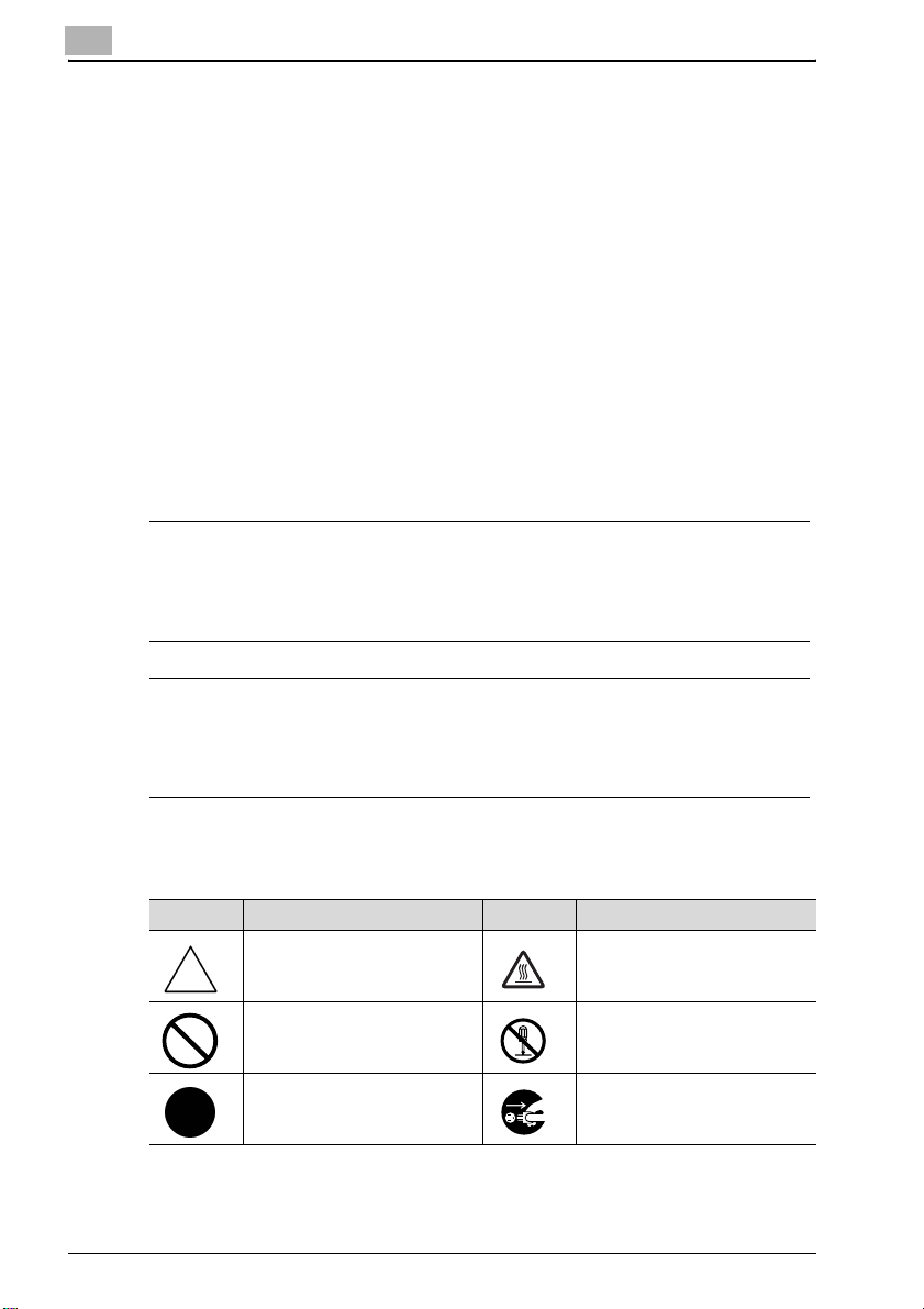
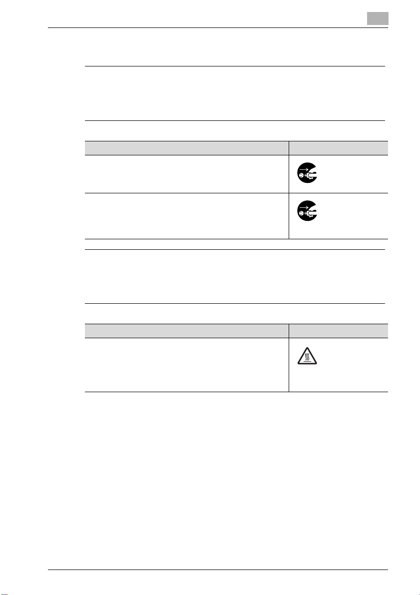
Meaning of symbols
Symbol Meaning Example Meaning
A triangle indicates a danger
against which you should take
precaution.
A diagonal line indicates a prohibited course of action.
A black circle indicates an imperative course of action.
1-4 bizhub PRO C6500 / bizhub PRO C6500e
This symbol warns against possible causes of burns.
This symbol warns against dismantling the device.
This symbol indicates you must
unplug the device.
Page 9
Introduction
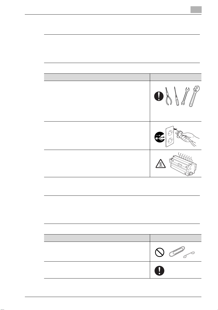
Operations before replacing any part
7 CAUTION
Ignoring this cautions could cause injury or damage to property.
% Do not ignore these safety advices.
Warning Symbol
When conducting a part replacement operation, be sure to get
guidance from the customer engineer. And also, read the CMS
Replacement Instructions carefully before conducting a part replacement operation by following the prescribed procedure and
using tools also prescribed. Be sure not to conduct any operations other than those described in the CMS Replacement Instructions. When the prescribed procedure and tools are not
employed, this may cause damage to the copier or you may get
injured.
Before starting operations, be sure to unplug the power cords
of the copier main body and the optional equipment from the
power outlet.
When the power cord is plugged into the power outlet, some
electrical components may be energized even if the power
switch is turned off. So, be careful not to get an electric shock.
The temperature gets high in the vicinity of the fusing unit. Be
careful not to come into contact with it, or you may get burned.
1
CMS part replacement operation
7 WARNING
Ignoring this warnings could cause serious injury or even death.
% Do not ignore these safety advices.
Warning Symbol
Do not allow any metal parts such as clips, staples and screws
to fall into the inside or opening of the copier.
They may cause a short circuit to the internal parts of the copier,
thus leading up to a risk of an electric shock or fire.
Check the wiring harness for squeezing and any other damage.
Current may leak, thus leading up to a risk of an electric shock
or fire.
bizhub PRO C6500 / bizhub PRO C6500e 1-5
Page 10
1
Introduction
Power plug
7 WARNING
Ignoring this warnings could cause serious injury or even death.
% Do not ignore these safety advices.
Warning Symbol
Be sure to avoid plugging or unplugging the power cord with a
wet hand. You may get an electric shock.
Be sure to plug the power cord securely into the power outlet.
Otherwise, a fire may result, or you may get an electric shock.
7 CAUTION
Ignoring this cautions could cause injury or damage to property.
% Do not ignore these safety advices.
Warning Symbol
When unplugging the power cord from the power outlet, be
careful not to pull the power cord. Otherwise, a fire may result
with the power cord damaged, or you may get an electric shock.
1-6 bizhub PRO C6500 / bizhub PRO C6500e
Page 11
Introduction
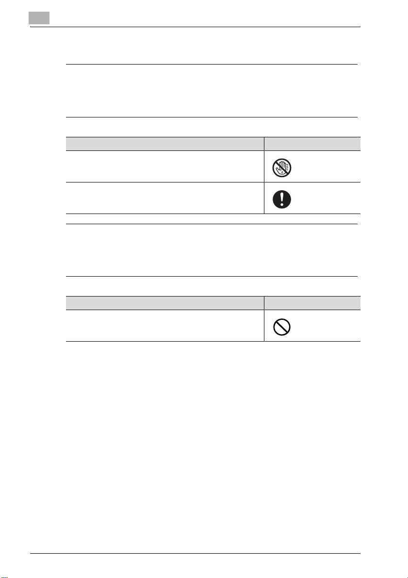
When any abnormal condition is found
7 WARNING
Ignoring this warnings could cause serious injury or even death.
% Do not ignore these safety advices.
7 CAUTION
Ignoring this cautions could cause injury or damage to property.
% Do not ignore these safety advices.
Warning Symbol
When the copier gets hot abnormally, or when it gives out
smoke, a foul smell or abnormal noise, turn off the power switch
at once. And then be sure to unplug the power cord from the
power outlet and contact our service technician.
When the copier is let fall or when the cover is damaged, turn off
the power switch at once. And then, be sure to unplug the power cord from the power outlet and contact our service technician. Using the copier as it is may lead up to a fire, or you may
get an electric shock.
1
Warning Symbol
Some internal parts of the copier develops a high temperature,
and you may get a burn when you come into contact with one
of these parts. When checking the internal parts while in a part
replacement operation, be careful not come into contact with a
section like these (around the fusing unit) with a symbol indicating "High Temperature" provided.
bizhub PRO C6500 / bizhub PRO C6500e 1-7
Page 12
1
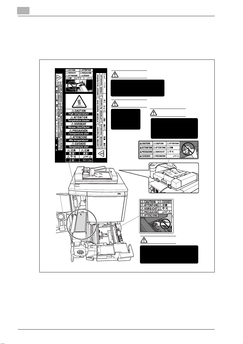
1.2 Caution notations and caution labels
For this copier, there are the caution notations or labels for safety operations
provided at the locations as shown below. Be sure to take every care to avoid
any accidents while in the part replacement operation.
CAUTION
DO NOT put your hand between
the main body and developing
fixing unit; otherwise you may
be injured.
CAUTION
The fixing unit is
very hot.
To avoid getting
burned DO NOT
TOUCH.
DO NOT INSERT your
finger into the two RADF
hinge portions; otherwise
you may be injured.
Introduction
CAUTION
CAUTION
DO NOT put your hand between
the main body and developing
fixing unit; otherwise you may be
injured.
1-8 bizhub PRO C6500 / bizhub PRO C6500e
Page 13
Introduction
1
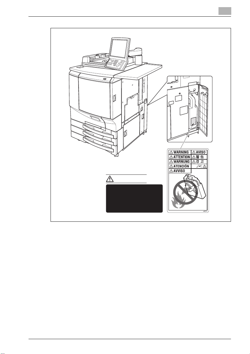
WARNING
DO NOT throw the toner
recovery box into a fire. If it
is thrown into a fire, the
toner may ignite and cause
a dangerous situation.
bizhub PRO C6500 / bizhub PRO C6500e 1-9
Page 14

1
Introduction
1-10 bizhub PRO C6500 / bizhub PRO C6500e
Page 15

2
bizhub PRO
C6500/bizhub PRO
C6500e
Page 16

Page 17
bizhub PRO C6500/bizhub PRO C6500e
2 bizhub PRO C6500/bizhub PRO C6500e
2.1 Maintenance procedure of the housing section
Removing the dust-proof filter 1 assy
Periodically replaced parts/cycle:
- Dust-proof filter 1 assy: Every 200,000 prints (actual replacement cycle:
Varies depending on the coverage, the developing roller drive distance
and temp/humidity)
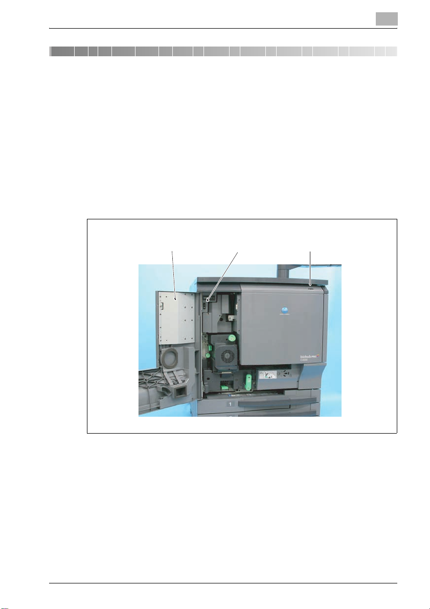
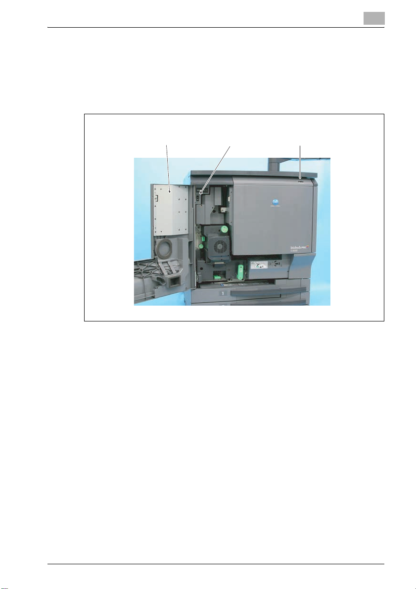
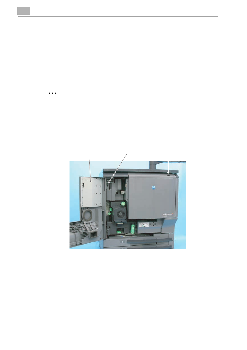
1 Turn OFF the sub power switch.
left front door main power switch sub power switch
2
2 Open the left front door, and then turn OFF the main power switch.
3 Unplug the power cord.
bizhub PRO C6500 / bizhub PRO C6500e 2-3
Page 18
2
bizhub PRO C6500/bizhub PRO C6500e
4 Remove the screw, and remove the filter cover.
screw filter cover
5 Remove the dust-proof filter 1 assy.
dust-proof filter 1 assy
Reinstalling the dust-proof filter 1 assy
% Reinstall the above parts following the removal steps in reverse.
2-4 bizhub PRO C6500 / bizhub PRO C6500e
Page 19
bizhub PRO C6500/bizhub PRO C6500e
Removing the dust-proof filter 2 assy
Periodically replaced parts/cycle:
- Dust-proof filter 2 assy: Every 200,000 prints
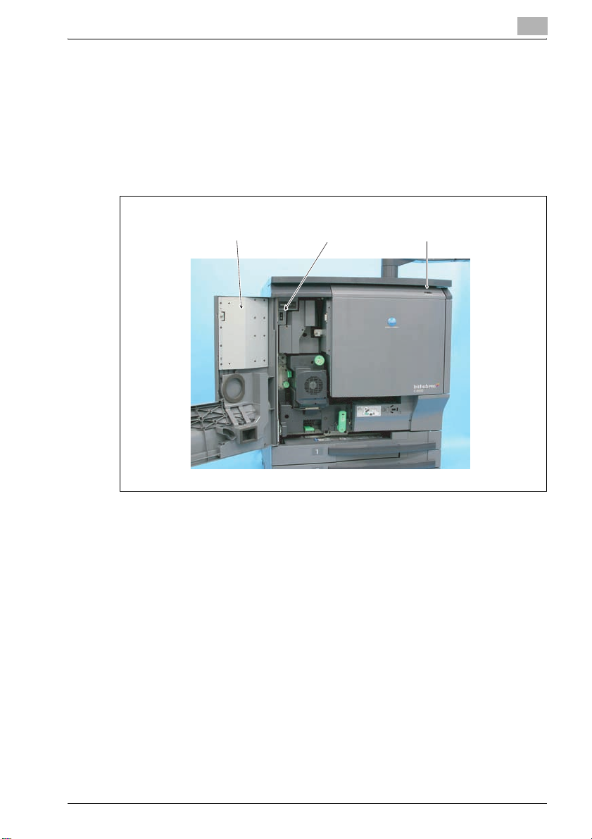
1 Turn OFF the sub power switch.
left front door main power switch sub power switch
2
2 Open the left front door, and then turn OFF the main power switch.
3 Unplug the power cord.
bizhub PRO C6500 / bizhub PRO C6500e 2-5
Page 20
2
bizhub PRO C6500/bizhub PRO C6500e
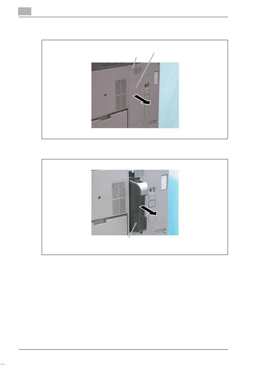
4 Loosen the two screws and remove the filter cover.
screws
filter cover
5 Pull out the dust-proof filter 2 assy from the filter cover.
filter cover
dust-proof filter 2 assy
Reinstalling the dust-proof filter 2 assy
% Reinstall the above parts following the removal steps in reverse.
2-6 bizhub PRO C6500 / bizhub PRO C6500e
Page 21
bizhub PRO C6500/bizhub PRO C6500e
2.2 Maintenance procedure of the toner collection box
Removing the toner collection box assy
Periodically replaced parts/cycle:
- Toner collection box assy: Every 50,000 prints
1 Turn OFF the sub power switch.
left front door main power switch sub power switch
2
2 Open the left front door, and then turn OFF the main power switch.
3 Unplug the power cord.
bizhub PRO C6500 / bizhub PRO C6500e 2-7
Page 22
2
bizhub PRO C6500/bizhub PRO C6500e
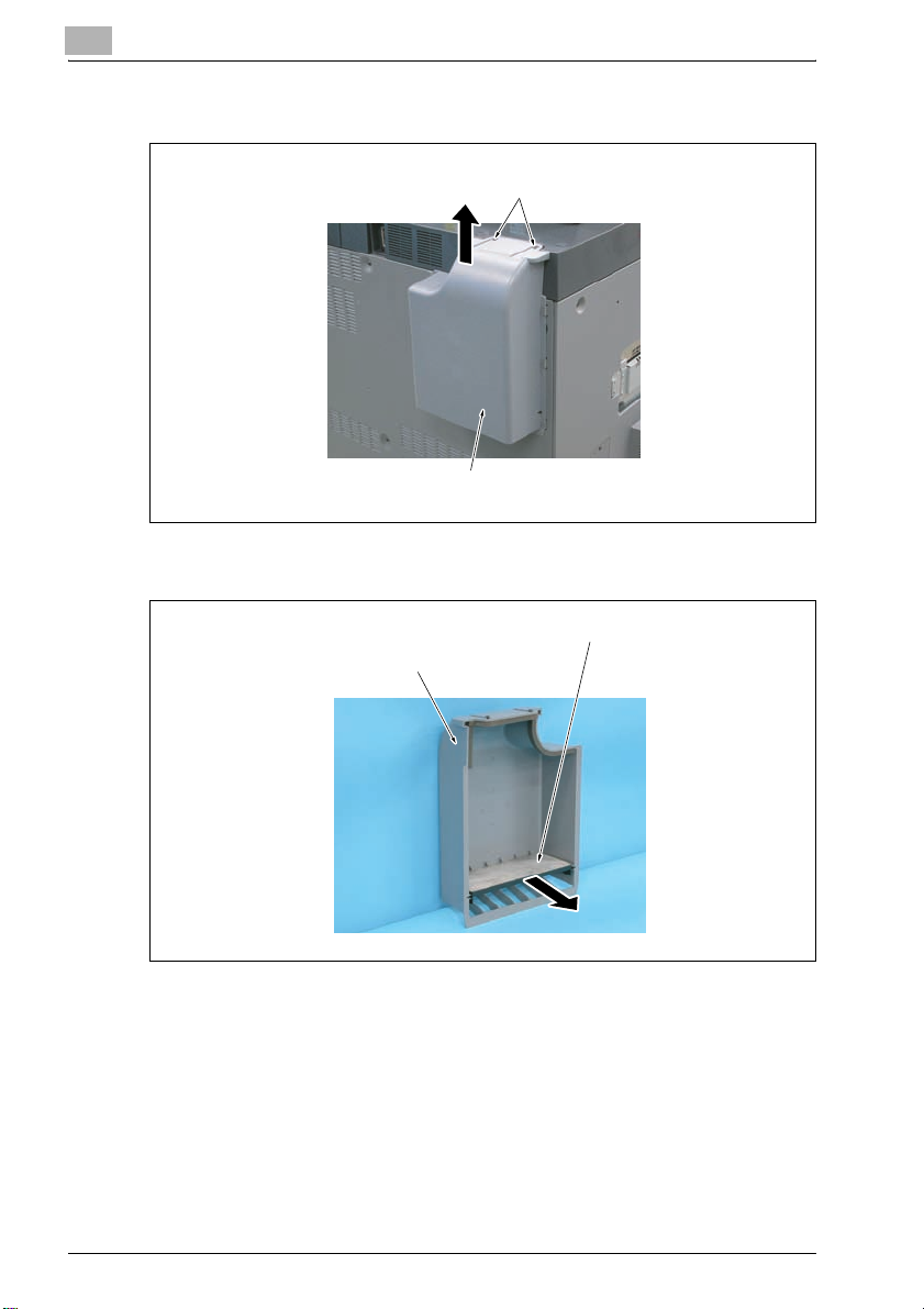
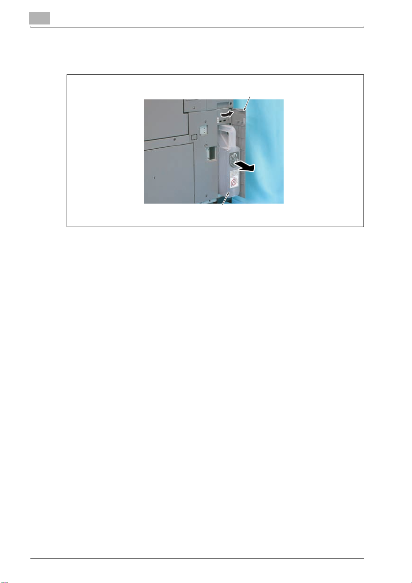
4 Open the toner collection door, and pull out the toner collection box
assy.
toner collection door
toner collection box assy
2-8 bizhub PRO C6500 / bizhub PRO C6500e
Page 23
bizhub PRO C6500/bizhub PRO C6500e
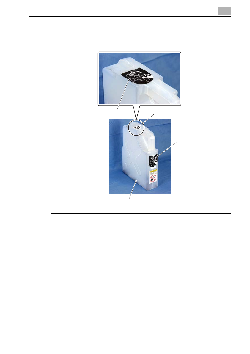
5 Peel off the label on the toner collection box assy and close the
opening of the toner collection box assy with the label.
2
label
toner collection box assy
Reinstalling the toner collection box assy
% Reinstall the above parts following the removal steps in reverse.
opening
label
bizhub PRO C6500 / bizhub PRO C6500e 2-9
Page 24
2
bizhub PRO C6500/bizhub PRO C6500e
2.3 Maintenance procedure of the paper feeding section
Removing the pick-up roller/paper feed roller rubber
Periodically replaced parts/cycle:
- Pick-up roller: Every 2,400,000 prints (actual replacement cycle: every
800,000 feed)
- Paper feed roller rubber: Every 400,000 prints (actual replacement cycle:
every 125,000 feed)
2
Note
The tray 1 was used to illustrate the replacement procedure below. The
procedure is the same for the tray 2 and tray 3.
1 Turn OFF the sub power switch.
left front door main power switch sub power switch
2 Open the left front door, and then turn OFF the main power switch.
3 Unplug the power cord.
2-10 bizhub PRO C6500 / bizhub PRO C6500e
Page 25
bizhub PRO C6500/bizhub PRO C6500e
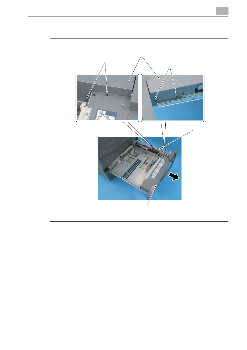
4 Pull out the paper feed tray 1.
2
screws
paper feed unit cover
screws
paper feed
unit cover
paper feed tray 1
5 Remove the four screws and remove the paper feed unit cover.
bizhub PRO C6500 / bizhub PRO C6500e 2-11
Page 26

2
bizhub PRO C6500/bizhub PRO C6500e
6 Disconnect the connector 1.
fixing shaft screw
connector 2
paper feed unit
screw
connector 1
7 Remove the screw and loosen the fixing shaft screw.
8 Slide the paper feed unit in the direction of the arrow, and lift the unit
to remove it disconnecting the connector 2.
2-12 bizhub PRO C6500 / bizhub PRO C6500e
Page 27

bizhub PRO C6500/bizhub PRO C6500e
9 Remove the two C-clips, slide the two bearings outward, and remove
the paper feed roller assy.
bearing
2
C-clips
paper feed roller assy
– Before installing the paper feed roller assy, make sure the rollers are
free of grease or dust.
bearing
bizhub PRO C6500 / bizhub PRO C6500e 2-13
Page 28

2
10 Remove the bearing.
C-clip 1
pick-up roller
arrow mark 1 arrow mark 2
bizhub PRO C6500/bizhub PRO C6500e
paper feed roller
C-clip 2
bearing
paper feed roller rubber
painted mark
11 Remove the C-clip 1 and remove the pick-up roller.
– When installing the pick-up roller, be sure that the arrow mark 1 is
facing toward the C-clip 1.
12 Remove the C-clip 2 and remove the paper feed roller.
– When installing the paper feed roller, be sure that the arrow mark 2
is facing toward the C-clip.
13 Remove the paper feed roller rubber from the paper feed roller.
– When installing the paper feed roller rubber, be sure that the
painted mark is facing toward the arrow mark 2.
Reinstalling the pick-up roller/paper feed roller rubber
% Reinstall the above parts following the removal steps in reverse.
2-14 bizhub PRO C6500 / bizhub PRO C6500e
Page 29

bizhub PRO C6500/bizhub PRO C6500e
Removing the separation roller rubber
Periodically replaced parts/cycle:
- Separation roller rubber: Every 400,000 prints (actual replacement cycle:
every 125,000 feed)
2
Note
The tray 1 was used to illustrate the replacement procedure below. The
procedure is the same for the tray 2 and tray 3.
1 Turn OFF the sub power switch.
left front door main power switch sub power switch
2
2 Open the left front door, and then turn OFF the main power switch.
3 Unplug the power cord.
bizhub PRO C6500 / bizhub PRO C6500e 2-15
Page 30

2
bizhub PRO C6500/bizhub PRO C6500e
4 Remove the paper feed roller assy. For details, refer to "Removing the
pick-up roller/paper feed roller rubber" on page 2-10.
separation roller
painted mark
separation roller rubber
C-clip
separation roller
5 Remove the C-clip and remove the separation roller.
– Before installing the separation roller, make sure the roller is free of
grease or dust.
6 Remove the separation roller rubber from the separation roller.
– When installing the separation roller rubber, be sure that the
painted mark is facing toward the C-clip.
Reinstalling the separation roller rubber
% Reinstall the above parts following the removal steps in reverse.
2-16 bizhub PRO C6500 / bizhub PRO C6500e
Page 31

bizhub PRO C6500/bizhub PRO C6500e
2.4 Maintenance procedure of the bypass feed tray section
Removing the pick-up roller/paper feed roller rubber
Periodically replaced parts/cycle:
- Pick-up roller: Every 4,000,000 prints (actual replacement cycle: every
800,000 feed)
- Paper feed roller rubber: Every 1,400,000 prints (actual replacement
cycle: every 125,000 feed)
1 Turn OFF the sub power switch.
left front door main power switch sub power switch
2
2 Open the left front door, and then turn OFF the main power switch.
3 Unplug the power cord.
bizhub PRO C6500 / bizhub PRO C6500e 2-17
Page 32

2
bizhub PRO C6500/bizhub PRO C6500e
4 While lifting the lever marked in the picture, turn the handle in the arrow
marked direction and pull out the ADU.
lever
5 Remove the six screws and remove the paper feed solenoid cover.
screws
paper feed solenoid cover screws
2-18 bizhub PRO C6500 / bizhub PRO C6500e
Page 33

bizhub PRO C6500/bizhub PRO C6500e
6 Remove the C-clip.
paper feeder roller unit
2
C-clipbearing
bizhub PRO C6500 / bizhub PRO C6500e 2-19
Page 34

2
bizhub PRO C6500/bizhub PRO C6500e
7 Remove the bearing and remove the paper feed roller unit.
– When installing the paper feed roller unit, be sure to fit the actuator
in the detection section of the paper empty sensor/BP (PS47).
paper empty
sensor/BP (PS47)
paper feed lift-up lever actuator
paper feeder roller unit
– When installing the paper feed roller unit, bring the tip of the paper
feed lift-up lever into contact with the undersurface of the plate of
the paper feed roller unit.
8 Remove the C-clip, pull out the shaft, and remove the pick-up roller
assy.
shaft
pick-up roller
2-20 bizhub PRO C6500 / bizhub PRO C6500e
pick-up roller assy
C-clip
Page 35

bizhub PRO C6500/bizhub PRO C6500e
9 Remove the pick-up roller from the pick-up roller assy.
10 Remove the paper feed roller assy from the shaft.
2
painted mark
paper feed roller assy
paper feed roller rubber
shaft
gear
11 Remove the paper feed roller rubber from the paper feed roller assy.
– When installing the paper feed roller rubber, be sure that the
painted mark is facing toward the gear.
Reintalling the pick-up roller/paper feed roller rubber
% Reinstall the above parts following the removal steps in reverse.
bizhub PRO C6500 / bizhub PRO C6500e 2-21
Page 36

2
bizhub PRO C6500/bizhub PRO C6500e
2.5 Maintenance procedure of the fusing section
7 CAUTION
Precaution for high temperature
Immediately after turning off the main power switch or the sub power switch,
the fusing section is very hot and you may get burnt.
% Be sure to start operations when the temperature cools down
sufficiently.
Removing the fusing unit
1 Turn OFF the sub power switch.
left front door main power switch sub power switch
2 Open the left front door, and then turn OFF the main power switch.
3 Unplug the power cord.
2-22 bizhub PRO C6500 / bizhub PRO C6500e
Page 37

bizhub PRO C6500/bizhub PRO C6500e
4 While lifting the lever marked in the picture, turn the handle in the arrow
marked direction and pull out the ADU.
2
lever
5 Open the front door and the toner supply section.
bizhub PRO C6500 / bizhub PRO C6500e 2-23
Page 38

2
bizhub PRO C6500/bizhub PRO C6500e
6 Remove the screw, and remove the connector cover.
screw connector cover
connector
7 Disconnect the connector.
2-24 bizhub PRO C6500 / bizhub PRO C6500e
Page 39

bizhub PRO C6500/bizhub PRO C6500e
8 Remove the screw, and remove the knob.
2
knob
screws
screw
front fusing cover
9 Remove the two screws and remove the front fusing cover.
bizhub PRO C6500 / bizhub PRO C6500e 2-25
Page 40

2
bizhub PRO C6500/bizhub PRO C6500e
10 Disconnect the two connectors.
reverse/exit section
screw
11 Open the reverse/exit section.
fusing unit
connectors
12 Remove the screw and remove the fusing unit.
– When installing/removing the fusing unit, be sure to hold both ends
of the unit and slide it toward you in the direction of the arrow before
lifting up the unit.
Reinstalling the fusing unit
% Reinstall the above parts following the removal steps in reverse.
2-26 bizhub PRO C6500 / bizhub PRO C6500e
Page 41

3
PF-601/HT504
Page 42

Page 43

PF-601/HT504
3 PF-601/HT504
3.1 Maintenance procedure of the tray section
Removing the pick-up rubber/paper feed roller
Periodically replaced parts/cycle:
- Pick-up rubber: Every 600,000 prints (actual replacement cycle: every
300,000 feed)
- Paper feed roller: Every 600,000 prints (actual replacement cycle: every
300,000 feed)
2
Note
The appearance of the collars is the same for the paper feed roller and
the separation roller. However, the collar of the paper feed roller has a
one-way mechanism inside, be sure not to mix up these two rollers.
1 Turn OFF the sub power switch.
3
left front door main power switch sub power switch
2 Open the left front door, and then trun OFF the main power switch.
3 Unplug the power cord.
bizhub PRO C6500 / bizhub PRO C6500e 3-3
Page 44

3
PF-601/HT504
4 Open the front door.
vertical
conveyance
unit guide plate
hole
tray lock lever
front door
tray
5 Open the vertical conveyance unit guide plate (tray 4 only).
3-4 bizhub PRO C6500 / bizhub PRO C6500e
Page 45

PF-601/HT504
6 Insert a screwdriver or a similar tool into the hole, lift up the tray lock
3
lever slightly, and pull out the tray.
– Do not pull out tray all the way. Hold tray so that the stopper on the
left side of the tray pushed in, and make the pick-up holder assy
placed horizontally (paper feed position).
stopper
pick-up holder assy
tray
bizhub PRO C6500 / bizhub PRO C6500e 3-5
Page 46

3
PF-601/HT504
7 Rotate the pick-up roller in the direction of the arrow (clockwise as
seen from the front side) and bring the coupling to the shown position.
C-clips
notch
flat part
rear bearing
metal plate
coupling
pick-up roller
front bearing
– Be sure not to rotate the pick-up roller against the direction of the
arrow forcibly, as the roller is designed not to rotate in that
direction.
rear bearing
8 Remove the two C-clips.
9 Remove the front bearing.
3-6 bizhub PRO C6500 / bizhub PRO C6500e
Page 47

PF-601/HT504
10 Move the rear bearing to the rear side.
11 Hold the pick-up roller assy by hand and lift and tilt the paper feed roller
3
– When installing the bearing, hold down the metal plate of the pick-
up roller assy slightly, and insert the flat part of the rear bearing
while keeping it horizontally into the notch of the metal plate. Then,
insert the front bearing in the same manner.
so that it rotates on the shaft of the pick-up roller to remove it from both
the notch of the bearing and the coupling.
– When removing the pick-up roller assy, be careful not to damage
the sensor with the metal plate.
sensor
coupling
bearing
pick-up roller
assy
paper feed roller
bizhub PRO C6500 / bizhub PRO C6500e 3-7
shaft
Page 48

3
PF-601/HT504
12 Remove the pick-up roller shaft from the arm of the paper feed guide
plate and remove the pick-up roller assy.
pick-up roller assy
arm
pick-up roller
shaft
13 Remove the C-clip, pull out the shaft, and remove the pick-up roller.
pick-up roller
C-clip
3-8 bizhub PRO C6500 / bizhub PRO C6500e
shaft
Page 49

PF-601/HT504
14 Remove the pick-up rubber from the pick-up roller.
15 Replace the pick-up rubber.
16 Remove the C-clip and remove the bearing 1.
3
bearing 1
C-clip
paper feed roller
bearing 2
shaft
17 Slide the bearing 2 and remove the paper feed roller together with the
shaft.
18 Remove the actuator from the shaft.
actuator
shaft
C-clip paper feed roller
collar
bizhub PRO C6500 / bizhub PRO C6500e 3-9
Page 50

3
PF-601/HT504
19 Remove the C-clip and pull out the paper feed roller from the collar.
20 Replace the paper feed roller.
collar of the paper feed rollercollar of the separation roller
– The appearance of the collars is the same for the paper feed roller
and the separation roller. However, the collar of the paper feed
roller has a one-way mechanism inside while the collar of the
separation roller has no one-way mechanism, be sure not to mix up
these two rollers.
Reinstalling the pick-up rubber/paper feed roller
% Reinstall the above parts following the removal steps in reverse.
3-10 bizhub PRO C6500 / bizhub PRO C6500e
Page 51

PF-601/HT504
Removing separation roller
Periodically replaced parts/cycle
- Separation roller: Every 600,000 prints (actual replacement cycle: every
300,000 feed)
2
Note
The appearance of the collars is the same for the paper feed roller and
the separation roller. However, the collar of the paper feed roller has a
one-way mechanism inside, be sure not to mix up these two rollers.
1 Turn OFF the sub power switch.
3
left front door main power switch sub power switch
2 Open the left front door, and then turn OFF the main power switch.
3 Unplug the power cord.
bizhub PRO C6500 / bizhub PRO C6500e 3-11
Page 52

3
PF-601/HT504
4 Open the front door.
vertical
conveyance
unit guide plate
hole
tray lock lever
front door
tray
5 Open the vertical conveyance unit guide plate (tray 4 only).
6 Insert a screwdriver or a similar tool into the hole, lift up the tray lock
lever slightly, and pull out the tray.
3-12 bizhub PRO C6500 / bizhub PRO C6500e
Page 53

PF-601/HT504
7 Remove two screws.
3
metal plate
separation roller assey
joint
coupling pin
screws
8 Disengage the coupling pin from the joint while pressing down the
metal plate of the separation roller assy, and remove the separation
roller assy.
– When installing the separation roller assy, press down the metal
plate of the separation roller assy and engage the coupling pin to
the joint.
bizhub PRO C6500 / bizhub PRO C6500e 3-13
Page 54

3
PF-601/HT504
9 Remove the C-clip of the separation roller assy and remove the
separation roller together with the shaft.
shaft separation roller C-clip
3-14 bizhub PRO C6500 / bizhub PRO C6500e
Page 55

PF-601/HT504
10 Pull out the gear, the collar and the separation roller from the shaft to
3
the arrow-marked direction, and remove them.
separation roller
shaft
11 Replace the pick-up roller.
collar
gear
collar of the paper feed rollercollar of the separation feed roller
2
Note
The appearance of the collars is the same for the paper feed roller and
the separation roller. However, the collar of the paper feed roller has a
one-way mechanism inside while the collar of the separation roller has no
one-way mechanism, be sure not to mix up these two rollers.
bizhub PRO C6500 / bizhub PRO C6500e 3-15
Page 56

3
PF-601/HT504
Reinstalling the separation roller
% Reinstall the above parts following the removal steps in reverse.
3-16 bizhub PRO C6500 / bizhub PRO C6500e
Page 57

4
DF-609
Page 58

Page 59

DF-609
4DF-609
4.1 Maintenance procedure of the paper feeding section
Removing the paper feed unit
1 Turn OFF the sub power switch.
left front door main power switch sub power switch
4
2 Open the left front door, and then trun OFF the main power switch.
3 Unplug the power cord.
bizhub PRO C6500 / bizhub PRO C6500e 4-3
Page 60

4
DF-609
4 Open the paper feed cover.
locks
paper feed cover
paper feed unit
paper feed guide
tabs
no paper
detection
actuator
positioning
hole
5 Release the two locks of the paper feed guide.
6 Turn the paper feed guide in the direction of the two arrows while
pushing in the paper feed unit to the paper feed cover side, and remove
the paper feed guide upward.
– When installing the paper feed guide, fit the three tabs in each
positioning hole.
– When installing the paper feed guide, be sure to put the no paper
detection actuator so that it protrudes out of the paper feed guide
as shown in the figure on the left.
4-4 bizhub PRO C6500 / bizhub PRO C6500e
Page 61

DF-609
4
7 Remove the screw and remove the shaft securing plate.
screw
shaft securing plate
paper feed unit
C-clip
bearing
8 Remove the two C-clips.
C-clip
bearing
bizhub PRO C6500 / bizhub PRO C6500e 4-5
Page 62

4
DF-609
9 Slide the two bearings inward, and remove the paper feed unit.
– When removing the paper feed unit, be sure not to damage the arm
with the shaft.
cover plate
– When installing the paper feed unit, make sure the arm is mounted
on the shaft.
– When installing the paper feed unit, insert the tab under the cover
plate as shown in the figure.
Reinstalling the paper feed unit
% Reinstall the above parts following the removal steps in reverse.
tab
arm
shaft
4-6 bizhub PRO C6500 / bizhub PRO C6500e
Page 63

DF-609
4
Removing the pick-up roller/paper feed roller
Periodically replaced parts/cycle
- Paper feed roller: Every 1,800,000 prints (actual replacement cycle: every
625,000 feed)
- Pick-up roller: Every 1,800,000 prints (actual replacement cycle: every
625,000 feed)
1 Turn OFF the sub power switch.
left front door main power switch sub power switch
2 Open the left front door, and then turn OFF the main power switch.
3 Unplug the power cord.
4 Remove the paper feed unit. For details, refer to "Removing the paper
feed unit" on page 4-3.
bizhub PRO C6500 / bizhub PRO C6500e 4-7
Page 64

4
DF-609
5 Remove the bearing.
bearing C-clip
6 Remove the C-clip.
7 Slide the gear in the direction of the arrow and remove the pin. Then
remove the gear and the belt in the direction of the arrow.
gear
belt pin
4-8 bizhub PRO C6500 / bizhub PRO C6500e
Page 65

DF-609
8 Remove the C-clip, then remove the gear and the pin.
gear
C-clip
– Be careful not to lose the pin as it may drop off the shaft when
removing the gear.
pin
9 Remove the arm and the pin.
arm pin
4
– Be careful not to lose the pin as it may drop off the shaft when
removing the arm.
bizhub PRO C6500 / bizhub PRO C6500e 4-9
Page 66

4
DF-609
10 Remove the C-clip, and remove the pick-up roller assy from the paper
feed roller assy.
pick-up roller assy
paper feed roller assy
C-clip
11 Remove the C-clip and pull out the paper feed roller from the shaft to
replace it with new one.
C-clip paper feed roller gear
arrow mark
– When installing the paper feed roller, make sure that the arrow mark
on the paper feed roller is facing the gear.
12 Remove the C-clip.
– Be careful not to lose the pin as it may drop off the shaft when
removing the C-clip.
4-10 bizhub PRO C6500 / bizhub PRO C6500e
Page 67

DF-609
4
13 Remove the pin and remove the pick-up roller.
pin
pick-up roller
C-clip
pick-up roller
pin
14 Remove the C-clip.
– Be careful not to lose the pin as it may drop off the shaft when
removing the C-clip.
15 Remove the pin and remove the pick-up roller.
Reinstalling the pick-up roller/paper feed roller
% Reinstall the above parts following the removal steps in reverse.
bizhub PRO C6500 / bizhub PRO C6500e 4-11
Page 68

4
DF-609
Removing the separation roller
Periodically replaced parts/cycle
- Separation roller: Every 1,800,000 prints (actual replacement cycle: every
625,000 feed)
1 Turn OFF the sub power switch.
left front door main power switch sub power switch
2 Open the left front door, and then turn OFF the main power switch.
3 Unplug the power cord.
4-12 bizhub PRO C6500 / bizhub PRO C6500e
Page 69

DF-609
4
4 Open the paper feed cover.
tabs
paper feed cover
tabs
5 Push the two tabs inward to release the lock and remove the
separation unit cover.
bizhub PRO C6500 / bizhub PRO C6500e 4-13
Page 70

4
DF-609
6 Pinch both ends of the roller shaft and raise the separation roller
straight up.
separation roller
7 Remove the separation unit and replace it with a new one.
separation unit
Reinstalling the pick-up roller/paper feed roller
% Reinstall the above parts following the removal steps in reverse.
4-14 bizhub PRO C6500 / bizhub PRO C6500e
Page 71

DF-609
4
Cleaning the timing sensor (PS302)
Periodically cleaned parts/cycle
- Timing sensor (PS302): Every 200,000 prints
1 Turn OFF the sub power switch.
left front door main power switch sub power switch
2 Open the left front door, and then turn OFF the main power switch.
3 Unplug the power cord.
bizhub PRO C6500 / bizhub PRO C6500e 4-15
Page 72

4
4 Secure the hinge adjustment bracket at 90 degrees.
hole
metal frame
screws
DF
screws
DF-609
5 Open the DF vertically.
6 Remove the two screws and open the metal frame in the direction of
the arrow.
– The two screws are different from each other, so try not to mix them
up.
7 Clean the timing sensor (PS302) through the hole with a blower brush
or a similar tool.
4-16 bizhub PRO C6500 / bizhub PRO C6500e
Page 73

DF-609
4
Removing the registration roller cover
1 Turn OFF the sub power switch.
left front door main power switch sub power switch
2 Open the left front door, and then turn OFF the main power switch.
3 Unplug the power cord.
bizhub PRO C6500 / bizhub PRO C6500e 4-17
Page 74

4
DF-609
4 Open the paper feed cover.
screws
paper feed cover
registration roller cover
paper feed tray
screws
5 Raise the paper feed tray straight up.
6 Remove the four screws and remove the registration roller cover.
Reinstalling the registration roller cover
% Reinstall the above parts following the removal steps in reverse.
4-18 bizhub PRO C6500 / bizhub PRO C6500e
Page 75

DF-609
4
Cleaning the registration roller
Periodically cleaned parts/cycle:
- Registration roller: Every 200,000 prints
1 Turn OFF the sub power switch.
left front door main power switch sub power switch
2 Open the left front door, and then turn OFF the main power switch.
3 Unplug the power cord.
bizhub PRO C6500 / bizhub PRO C6500e 4-19
Page 76

4
DF-609
4 Remove the registration roller cover. For detail, refer to "Removing the
registration roller cover" on page 4-17.
registration rollers
5 Soak cotton waste with alcohol and wipe the three registration rollers
with it.
6 Reinstall the registration roller cover. For details, refer to "Reinstalling
the registration roller cover" on page 4-18.
4-20 bizhub PRO C6500 / bizhub PRO C6500e
Page 77

DF-609
4
Cleaning the registration sensor (PS301)
Periodically cleaned parts/cycle
Registration sensor: Every 200,000 prints
1 Turn OFF the sub power switch.
left front door main power switch sub power switch
2 Open the left front door, and then turn OFF the main power switch.
3 Unplug the power cord.
bizhub PRO C6500 / bizhub PRO C6500e 4-21
Page 78

4
DF-609
4 Remove the registration roller cover. For details, refer to "Removing the
registration roller cover" on page 4-17.
registration sensor (PS301)
5 Clean the registration sensor (PS301) with a blower brush or a similar
tool.
6 Reinstall the registration roller cover. For details, refer to "Reinstalling
the registration roller cover" on page 4-18.
4-22 bizhub PRO C6500 / bizhub PRO C6500e
Page 79

5
Appendix
Page 80

Page 81

Appendix
5 Appendix
5.1 Replacement parts list
Main body
Part name Part number
Toner collection box A03UR7020
Dust-proof filter 1 (right side) exchanging assy A03UR7010
Dust-proof filter 2 (rear side) 65AAR7180
Feed / reverse (separation) rubber (tray 1) 25SA40960E
Feed / reverse (separation) rubber (tray 2) 25SA40960E
Feed / reverse (separation) rubber (tray 3) 25SA40960E
Feed / reverse (separation) rubber (bypass) 25SA40960E
Paper feed roller (tray 1) 56AA-458
Paper feed roller (tray 2) 56AA-458
Paper feed roller (tray 3) 56AA-458
Paper feed roller (bypass) 65AA-520
Charging corona Y (page) A03UR7030
Charging corona M (page) A03UR7030
Charging corona C (page) A03UR7030
Charging corona K (page) A03UR7030
Fusing unit A03UR71800
5
bizhub PRO C6500 / bizhub PRO C6500e 5-3
Page 82

5
Appendix
Paper feeding unit PF-601
Part name Part number
Pick-up rubber 55VA4111
Paper feed roller 55VA-483
Separation roller 55VA-483
Document feeder DF-609
Part name Part number
Pick-up roller 13YH4039
Paper feed roller 13YH4064
Separation roller 20AJ4015
5-4 bizhub PRO C6500 / bizhub PRO C6500e
 Loading...