

Page 1
Page 2

Page 3

Contents
1 Introduction
1.1 Energy Star® ..................................................................................... 1-4
What is an Energy Star® product? ................................................ 1-4
1.2 Trademarks and registered trademarks ......................................... 1-5
License information ........................................................................ 1-5
OpenSSL Statement ...................................................................... 1-6
1.3 Software licence agreement ............................................................ 1-9
1.4 Explanation of manual conventions .............................................. 1-11
Safety advices .............................................................................. 1-11
Sequence of action ...................................................................... 1-11
Tips .............................................................................................. 1-12
Special text markings ................................................................... 1-12
2 Installation and operation precautions
2.1 Safety information ............................................................................ 2-3
Warning and Precaution Symbols .................................................. 2-3
Meaning of Symbols ...................................................................... 2-4
Disassemble and modification ....................................................... 2-4
Power cord ..................................................................................... 2-5
Power source ................................................................................. 2-6
Power plug ..................................................................................... 2-7
Grounding ...................................................................................... 2-7
Installation ...................................................................................... 2-8
Ventilation ...................................................................................... 2-9
Actions in response to troubles ..................................................... 2-9
Consumables ............................................................................... 2-10
When moving the machine .......................................................... 2-11
Before successive holidays .......................................................... 2-11
2.2 Regulation notices .......................................................................... 2-12
CE Marking (Declaration of conformity) for users
of the European Union (EU) ......................................................... 2-12
USER INSTRUCTIONS FCC PART 15 -
RADIO FREQUENCY DEVICES (for U.S.A. users) ....................... 2-12
INTERFERENCE-CAUSING EQUIPMENT STANDARD
(ICES-003 ISSUE 4) (for Canada users) ....................................... 2-13
For users in countries not subject to class B regulations ............ 2-13
C352P x-1
Page 4

Laser safety ...................................................................................2-13
Internal laser radiation ..................................................................2-14
CDRH regulations .........................................................................2-15
For European users .......................................................................2-16
For Denmark users .......................................................................2-16
For Finland, Sweden users ...........................................................2-16
For Norway users ..........................................................................2-17
Laser safety label ..........................................................................2-18
Ozone release ...............................................................................2-19
Acoustic noise (for European users only) .....................................2-19
For EU member states only ..........................................................2-19
2.3 Caution notations and labels ..........................................................2-20
2.4 Space requirements ........................................................................2-21
2.5 Operation precautions ....................................................................2-22
Power source ................................................................................2-22
Operating environment .................................................................2-22
Storage of printed pages ..............................................................2-22
2.6 Part names and their functions ......................................................2-23
Options .........................................................................................2-23
Outside of machine .......................................................................2-26
Inside of machine ..........................................................................2-32
Saddle stitcher SD-503/mailbin kit MT-501 .................................2-34
Finisher FS-514/output tray OT-601/punch kit PK-510 ................2-35
Control panel ................................................................................2-38
2.7 Basic operations ..............................................................................2-39
Turning on the machine ................................................................2-39
Turning off the machine ................................................................2-40
Automatically canceling the settings (automatic panel reset) .......2-41
Automatically conserving energy (Low Power mode) ...................2-41
Automatically conserving energy (Sleep mode) ............................2-42
Power supply ................................................................................2-43
2.8 Connecting to a computer ..............................................................2-44
Compatible interfaces ...................................................................2-44
Connection diagram .....................................................................2-45
x-2 C352P
Page 5

3 Setting up the printer driver
3.1 About the provided printer drivers .................................................. 3-3
Printer drivers and supported operating systems .......................... 3-3
System requirements ..................................................................... 3-4
Setting up the system .................................................................... 3-5
3.2 Installing the printer driver .............................................................. 3-6
When used with Windows .............................................................. 3-6
Installing the printer driver using the Add Printer Wizard .............. 3-8
For Windows XP/Server 2003 ........................................................ 3-8
For Windows 98SE/Me/2000/NT 4.0 ........................................... 3-10
Installing the printer driver using Plug and Play ........................... 3-12
For Windows 98SE ....................................................................... 3-12
For Windows Me/2000 ................................................................. 3-13
For Windows XP/Server 2003 ...................................................... 3-15
Uninstalling the printer driver ....................................................... 3-17
When used with Macintosh .......................................................... 3-18
Installing the printer driver ........................................................... 3-19
For Mac OS X ............................................................................... 3-19
Selecting a printer ........................................................................ 3-20
For Mac OS X ............................................................................... 3-20
For Mac OS 9.2 ............................................................................ 3-22
Uninstalling the printer driver ....................................................... 3-23
For Mac OS X ............................................................................... 3-23
For Mac OS 9.2 ............................................................................ 3-24
3.3 Printing operations ......................................................................... 3-25
For Windows ................................................................................ 3-25
Printing operation ......................................................................... 3-25
Test printing ................................................................................. 3-26
For Macintosh .............................................................................. 3-27
Printing operation ......................................................................... 3-27
3.4 Setting up network printing ........................................................... 3-28
Overview of network functions .................................................... 3-28
Network functions ........................................................................ 3-28
Features of the network functions ............................................... 3-29
Network connection methods that can be selected
in each Windows operating system ............................................. 3-31
Specifying the TCP/IP settings .................................................... 3-34
Accessing PageScope Web Connection ..................................... 3-37
SMB printing ................................................................................ 3-38
Operations on this machine ......................................................... 3-38
Printer driver settings (For Windows 98SE/Me) ........................... 3-40
Printer driver settings (For Windows 2000/XP/Server 2003) ........ 3-40
C352P x-3
Page 6

LPR printing ..................................................................................3-41
Operations on this machine ..........................................................3-41
Printer driver settings (For Windows 2000/XP/Server 2003) ........3-41
Printer driver settings (For Windows NT 4.0) ................................3-42
Port 9100 printing (Windows 98SE/Me/2000/XP/Server 2003) ....3-43
Operations on this machine ..........................................................3-43
Printer driver settings (Windows 2000/XP/server 2003) ...............3-44
Installing the Peer to Peer Printing Tool to connect
using Port 9100 (Windows 98SE/Me) ...........................................3-45
Printer driver settings when the Peer to Peer Printing Tool
is installed to connect using Port 9100 (Windows 98SE/Me) .......3-46
IPP printing (Windows 2000/XP/Server 2003) ..............................3-47
Operations on this machine ..........................................................3-47
Installing the printer driver ............................................................3-49
Printing with NetWare ...................................................................3-51
For remote printer mode with NetWare 4.x Bindery Emulation ....3-51
For print server mode with NetWare 4.x Bindery Emulation .........3-54
For NetWare 4.x remote printer mode (NDS) ................................3-57
For NetWare 4.x/5.x/6 Print Server mode (NDS) ..........................3-59
For NetWare 5.x/6 Novell Distributed Print Services (NDPS) .......3-61
Specifying client (Windows) settings when using
the NetWare server .......................................................................3-62
Printing with Macintosh ................................................................3-63
Operations on this machine ..........................................................3-63
Specifying the AppleTalk settings ................................................3-63
Specifying the Bonjour settings ....................................................3-65
Specifying Macintosh settings ......................................................3-67
For Mac OS X ...............................................................................3-67
For Mac OS 9.2 .............................................................................3-68
4 Specifying printer driver settings
4.1 Specifying the printer driver basic settings ....................................4-3
For Windows ...................................................................................4-3
To display the printer driver setup dialog box ................................4-3
For Macintosh .................................................................................4-4
4.2 Setting up the PCL driver ..................................................................4-5
Selecting the printer ........................................................................4-5
Settings ...........................................................................................4-6
Common settings ............................................................................4-6
Specifying the Setup tab settings .................................................4-10
Printing to suit the paper size .......................................................4-10
Specifying a custom size ..............................................................4-12
Selecting the paper source ...........................................................4-13
Assigning a paper type to a paper tray .........................................4-13
Specifying Double-sided/Booklet printing ....................................4-15
x-4 C352P
Page 7

Printing multiple pages on one page (N in 1) ............................... 4-16
Setting the file margin .................................................................. 4-17
Stapling ........................................................................................ 4-18
Hole punching .............................................................................. 4-18
Fold & Staple ................................................................................ 4-19
Selecting the output method ....................................................... 4-20
Specifying Account Track settings .............................................. 4-22
Specifying the Per Page Setting tab settings .............................. 4-24
Printing documents with a front cover/back cover ...................... 4-24
Printing multiple pages ................................................................ 4-25
Chapter ........................................................................................ 4-25
Per Page setting ........................................................................... 4-26
Specifying the Overlay tab settings ............................................. 4-27
Printing different original documents together (Overlay) ............. 4-27
Editing forms ................................................................................ 4-29
Specifying the Watermark tab settings ........................................ 4-31
Printing a watermark .................................................................... 4-31
Editing a watermark ..................................................................... 4-32
Printing the document number .................................................... 4-33
Copy protect ................................................................................ 4-34
Specifying the Quality tab settings .............................................. 4-36
Specifying settings ....................................................................... 4-37
Specifying the Font tab settings .................................................. 4-38
Replacing fonts ............................................................................ 4-38
Specifying the Option tab settings ............................................... 4-39
Selecting options ......................................................................... 4-40
Saving the driver settings ............................................................. 4-42
To save the driver settings ........................................................... 4-42
Viewing the settings ..................................................................... 4-44
Deleting the settings .................................................................... 4-44
4.3 Setting up the PostScript driver (Windows) ................................. 4-45
Selecting the printer ..................................................................... 4-45
Settings ........................................................................................ 4-47
Common settings ......................................................................... 4-47
Specifying the Setup tab settings ................................................ 4-53
Printing to suit the paper size ...................................................... 4-54
Saving a custom sizes ................................................................. 4-55
Selecting the output method ....................................................... 4-56
Specifying Account Track settings .............................................. 4-58
Specifying the Layout tab settings ............................................... 4-60
Printing multiple pages on one page (N in 1) ............................... 4-61
Double-sided printing .................................................................. 4-62
Setting the file margin .................................................................. 4-62
Stapling ........................................................................................ 4-62
Fold & Staple ................................................................................ 4-63
Hole punching .............................................................................. 4-63
C352P x-5
Page 8

Specifying the Per Page Setting tab settings ...............................4-64
Printing documents with a front cover/back cover .......................4-64
Specifying the Watermark tab settings .........................................4-65
Printing a watermark .....................................................................4-65
Editing a watermark ......................................................................4-66
Specifying the Quality tab settings ...............................................4-68
Specifying settings ........................................................................4-69
Font settings .................................................................................4-70
Specifying the Option tab settings ...............................................4-71
Specifying settings ........................................................................4-72
Saving the driver settings .............................................................4-74
To save the driver settings ............................................................4-74
Viewing the settings ......................................................................4-76
Changing the settings ...................................................................4-76
4.4 Setting up the PPD driver (Windows) ............................................4-77
Settings .........................................................................................4-77
Specifying the Paper tab settings .................................................4-81
Specifying settings ........................................................................4-81
Specifying the Device Options tab settings ..................................4-82
Specifying settings ........................................................................4-82
Specifying the options ..................................................................4-84
To select an option .......................................................................4-84
4.5 Setting up the PPD driver (Mac OS 9.2) .........................................4-86
Settings .........................................................................................4-86
Page Setup dialog box .................................................................4-86
Print dialog box .............................................................................4-88
Page setup ....................................................................................4-91
Basic settings (Page Attributes) ....................................................4-91
Custom Page Sizes .......................................................................4-93
PostScript Options ........................................................................4-94
Printing ..........................................................................................4-95
Basic settings (General) ................................................................4-95
Printing multiple pages on one page (Layout) ..............................4-97
Printer-specific options (Finishing Options 1 to 4) ........................4-98
Setting options ............................................................................4-100
Specifying settings ......................................................................4-100
x-6 C352P
Page 9

4.6 Setting up the PPD driver (Mac OS X) ........................................ 4-102
Settings ...................................................................................... 4-102
Page Setup dialog box ............................................................... 4-102
Print dialog box .......................................................................... 4-104
Page setup ................................................................................. 4-108
Basic settings (Page Attributes) ................................................. 4-108
Custom Paper Size .................................................................... 4-110
Printing ....................................................................................... 4-111
Basic settings (Copies & Pages) ................................................ 4-111
Printing multiple pages on one page (Layout) ........................... 4-112
Paper Feed ................................................................................. 4-113
Security ...................................................................................... 4-114
Finishing ..................................................................................... 4-117
Quality ........................................................................................ 4-119
Setup .......................................................................................... 4-121
Setting options ........................................................................... 4-122
Specifying settings ..................................................................... 4-122
Saving the driver settings ........................................................... 4-124
To save the driver settings ......................................................... 4-124
Viewing the settings ................................................................... 4-125
Changing the settings ................................................................ 4-125
5 Control panel settings
5.1 Control panel ..................................................................................... 5-3
Available keys ................................................................................ 5-3
Basic operations ............................................................................ 5-4
Basic menu operations .................................................................. 5-4
Sleep mode .................................................................................... 5-6
Administrator password ................................................................. 5-8
5.2 Overview of utility mode parameters ............................................ 5-10
Settings menu list ......................................................................... 5-10
5.3 Parameters ...................................................................................... 5-30
Job Operation .............................................................................. 5-30
Paper Tray .................................................................................... 5-31
User Setting ................................................................................. 5-32
Admin. Setting .............................................................................. 5-38
HDD Password ............................................................................. 5-43
HDD Formatting ........................................................................... 5-43
Overwrite All ................................................................................. 5-43
Overwrite Temp. ........................................................................... 5-43
O.W. Priority ................................................................................. 5-44
Encryption Key ............................................................................. 5-45
Banner Printing ............................................................................ 5-46
C352P x-7
Page 10

6 Loading copy paper
6.1 Paper ..................................................................................................6-3
Possible paper sizes .......................................................................6-3
Paper types and paper capacities ..................................................6-5
Special paper ..................................................................................6-6
Precautions for paper .....................................................................6-8
Paper storage .................................................................................6-8
Print area .........................................................................................6-9
Auto tray switch feature ..................................................................6-9
Order for selecting the paper trays ...............................................6-10
6.2 Loading copy paper ........................................................................6-11
Loading paper into the Tray 1 .......................................................6-11
Loading paper into the tray 2, 3 or 4 ............................................6-15
Loading paper into the LCT ..........................................................6-17
Loading paper into the bypass tray ..............................................6-19
6.3 Specifying finishing settings ..........................................................6-23
Stapling prints (Staple settings) ....................................................6-23
Punching holes in prints (Punch settings) .....................................6-24
Specifying center binding .............................................................6-25
7 Replacing consumables
7.1 Replacing the toner cartridge ..........................................................7-3
To replace the toner cartridge ........................................................7-5
7.2 Replacing the staples ........................................................................7-8
To replace the staple cartridge in the finisher .................................7-8
To replace the staple cartridge in saddle stitcher .........................7-10
7.3 Replacing the waste toner box ......................................................7-13
To replace the waste toner box ....................................................7-14
8 Maintenance
8.1 Cleaning .............................................................................................8-3
Housing ...........................................................................................8-3
Control panel ..................................................................................8-3
Paper take-up roller ........................................................................8-4
Electrostatic charger wire ...............................................................8-4
Print head ........................................................................................8-5
Emptying the waste containers ......................................................8-6
To empty the hole-punch waste container .....................................8-7
8.2 When the message “Preventive Maintenance Time” appears ......8-8
x-8 C352P
Page 11

9 Troubleshooting
9.1 When the message “Trouble” appears
(call technical representative) ......................................................... 9-3
To call the technical representative ............................................... 9-3
9.2 When the message “Paper Misfeed at” appears ........................... 9-4
Paper misfeed indications .............................................................. 9-5
To clear a paper misfeed in the bypass tray .................................. 9-7
To clear a paper misfeed in the ADU ............................................. 9-9
To clear a paper misfeed in the tray 1 ......................................... 9-10
To clear a paper misfeed in the tray 2 ......................................... 9-12
To clear a paper misfeed in a paper tray (tray 3 or 4) .................. 9-13
To clear a paper misfeed in the LCT ............................................ 9-14
To clear a paper misfeed in the right-side door ........................... 9-15
To clear a paper misfeed in the fusing unit .................................. 9-18
To clear a banner paper misfeed ................................................. 9-22
To clear a paper misfeed in the finisher ....................................... 9-27
To clear a paper misfeed in the mailbin ....................................... 9-30
To clear a paper misfeed in the saddle stitcher ........................... 9-32
9.3 When the message “Replenish paper” appears .......................... 9-34
To replenish paper ....................................................................... 9-34
9.4 Clearing a staple jam ...................................................................... 9-35
To clear jammed staples in the finisher ....................................... 9-35
To clear jammed staples in the saddle stitcher ........................... 9-39
9.5 When “near life limit” appears ....................................................... 9-42
9.6 Simple troubleshooting .................................................................. 9-43
Main unit ...................................................................................... 9-43
Finisher ......................................................................................... 9-44
Printer driver ................................................................................. 9-45
9.7 Main messages and their remedies .............................................. 9-48
C352P x-9
Page 12

10 Additional settings
10.1 Using PageScope Web Connection ...............................................10-3
System Requirements ...................................................................10-3
Accessing PageScope Web Connection ......................................10-4
Page Structure ..............................................................................10-5
Cache Function of Web Browsers ................................................10-7
On Internet Explorer ......................................................................10-7
On Netscape Navigator ................................................................10-7
Logging In to the Administrator Mode ..........................................10-8
User mode ..................................................................................10-11
System tab ..................................................................................10-12
Job tab ........................................................................................10-13
Box tab .......................................................................................10-13
Print tab ......................................................................................10-14
Administrator mode ....................................................................10-15
Basic operation ...........................................................................10-15
System tab ..................................................................................10-16
Job tab ........................................................................................10-17
Box tab .......................................................................................10-17
Print tab ......................................................................................10-18
Network tab ................................................................................10-18
10.2 Box operations ...............................................................................10-20
Available parameters ..................................................................10-20
Opening Boxes ...........................................................................10-21
To open a box .............................................................................10-23
Checking Box Information and Downloading Documents ..........10-24
Changing the Box Settings .........................................................10-26
Deleting a Box .............................................................................10-28
Creating Boxes ...........................................................................10-30
10.3 Managing print jobs ......................................................................10-32
Specifying job operations ...........................................................10-32
Storing jobs .................................................................................10-34
Recalling a job ............................................................................10-34
Printing when account track settings have been specified ........10-38
Setting procedure (for Windows) ................................................10-39
Setting procedure (for Mac OS X) ...............................................10-40
Job operations in PageScope Web Connection .........................10-41
x-10 C352P
Page 13

10.4 Printing on Banner Paper ............................................................. 10-42
Paper .......................................................................................... 10-42
Paper types ................................................................................ 10-42
Printer Drivers and Supported Operating Systems ................... 10-43
Specifying Printer Driver Settings .............................................. 10-43
To specify printer driver settings ................................................ 10-43
Printing ....................................................................................... 10-44
To print ....................................................................................... 10-44
11 Appendix
11.1 Specifications ................................................................................. 11-3
bizhub C352P ............................................................................... 11-3
Option specifications ................................................................... 11-6
Automatic Duplex Unit AD-503 .................................................... 11-6
Paper Feed Cabinet PC-103 ........................................................ 11-6
Paper Feed Cabinet PC-203 ........................................................ 11-7
Paper Feed Cabinet PC-403 ........................................................ 11-7
Finisher FS-514 ............................................................................ 11-8
Punch kit PK-510 ......................................................................... 11-9
Saddle stitcher SD-503 ................................................................ 11-9
Output tray OT-601 .................................................................... 11-10
Mailbin kit MT-501 ..................................................................... 11-10
11.2 Configuration page ....................................................................... 11-11
11.3 Font list .......................................................................................... 11-12
PCL font list ................................................................................ 11-12
PS font list .................................................................................. 11-13
11.4 Test page ....................................................................................... 11-14
11.5 Glossary ......................................................................................... 11-15
11.6 Index .............................................................................................. 11-20
C352P x-11
Page 14

x-12 C352P
Page 15

1
Introduction
Page 16

Page 17

Introduction
1 Introduction
Thank you for choosing this machine.
This manual contains details on the operation of the various functions of the
machine, precautions on its use, and basic troubleshooting procedures. In
order to ensure that this machine is used correctly and efficiently, carefully
read this manual before using the machine. After reading the manual, store
it in the designated holder so that it can easily be referred to when questions
or problems arise during operation.
The illustrations used in this manual may appear slightly different from views
of the actual equipment.
1
C352P 1-3
Page 18

1
1.1 Energy Star®
As an Energy Star® Partner, we have determined that this machine meets the
Energy Star® Guidelines for energy efficiency.
What is an Energy Star® product?
An Energy Star® product has a special feature that allows it to automatically
switch to a “low-power mode” after a period of inactivity. An Energy Star®
product uses energy more efficiently, saves you money on utility bills and
helps protect the environment.
Introduction
1-4 C352P
Page 19

Introduction
1.2 Trademarks and registered trademarks
KONICA MINOLTA, KONICA MINOLTA Logo, and The essentials of imaging
are registered trademarks or trademarks of KONICA MINOLTA HOLDINGS,
INC.
PageScope and bizhub are registered trademarks or trademarks of KONICA
MINOLTA BUSINESS TECHNOLOGIES, INC.
Netscape Communications, the Netscape Communications logo, Netscape
Navigator, Netscape Communicator, and Netscape are trademarks of Netscape Communications Corporation.
This machine is based in part on the work of the Independent JPEG Group.
Compact-VJE
Copyright 1986-2003 VACS Corp.
RC4® is a registered trademark or trademark of RSA Security Inc. in the United States and/or other countries.
RSA® is a registered trademark or trademark of RSA Security Inc. RSA
BSAFE® is a registered trademark or trademark of RSA Security Inc. in the
United States and/or other countries.
License information
This product includes RSA BSAFE Cryptographic software from RSA Security Inc.
1
C352P 1-5
Page 20

1
Introduction
OpenSSL Statement
OpenSSL License
Copyright © 1998-2000 The OpenSSL Project. All rights reserved.
Redistribution and use in source and binary forms, with or without modification, are permitted provided that the following conditions are met:
1. Redistributions of source code must retain the above copyright notice,
this list of conditions and the following disclaimer.
2. Redistributions in binary form must reproduce the above copyright notice, this list of conditions and the following disclaimer in the documentation and/or other materials provided with the distribution.
3. All advertising materials mentioning features or use of this software must
display the following acknowledgment:
“This product includes software developed by the OpenSSL Project for
use in the OpenSSL Toolkit. (http://www.openssl.org/)”
4. The names “OpenSSL Toolkit” and “OpenSSL Project” must not be used
to endorse or promote products derived from this software without prior
written permission. For written permission, please contact opensslcore@openssl.org.
5. Products derived from this software may not be called “OpenSSL” nor
may “OpenSSL” appear in their names without prior written permission
of the OpenSSL Project.
6. Redistributions of any form whatsoever must retain the following acknowledgment:
“This product includes software developed by the OpenSSL Project for
use in the OpenSSL Toolkit (http://www.openssl.org/)”
THIS SOFTWARE IS PROVIDED BY THE OpenSSL PROJECT “AS IS” AND
ANY EXPRESSED OR IMPLIED WARRANTIES, INCLUDING, BUT NOT LIMITED TO, THE IMPLIED WARRANTIES OF MERCHANTABILITY AND FITNESS FOR A PARTICULAR PURPOSE ARE DISCLAIMED. IN NO EVENT
SHALL THE OpenSSL PROJECT OR ITS CONTRIBUTORS BE LIABLE FOR
ANY DIRECT, INDIRECT, INCIDENTAL, SPECIAL, EXEMPLARY, OR CONSEQENTIAL DAMAGES (INCLUDING, BUT NOT LIMITED TO, PROCUREMENT OF SUBSTITUTE GOODS OR SERVICES; LOSS OF USE, DATA, OR
PROFITS; OR BUSINESS INTERRUPTION) HOWEVER CAUSED AND ON
ANY THEORY OF LIABILITY, WHETHER IN CONTRACT, STRICT LIABILITY,
OR TORT (INCLUDING NEGLIGENCE OR OTHERWISE) ARISING IN ANY
WAY OUT OF THE USE OF THIS SOFTWARE, EVEN IF ADVISED OF THE
POSSIBILITY OF SUCH DAMAGE.
This product includes cryptographic software written by Eric Young
(eay@crypt-Soft.com). This product includes software written by Tim Hudson (tjh@cryptsoft.com).
1-6 C352P
Page 21

Introduction
Original SSLeay License
Copyright © 1995-1998 Eric Young (eay@cryptsoft.com) All rights reserved.
This package is an SSL implementation written by Eric Young (eay@cryptsoft.com).
The implementation was written so as to conform with Netscapes SSL.
This library is free for commercial and non-commercial use as long as the following conditions are aheared to. The following conditions apply to all code
found in this distribution, be it the RC4, RSA, Ihash, DES, etc., code; not just
the SSL code.
The SSL documentation included with this distribution is covered by the
same copyright terms except that the holder is Tim Hudson (tjh@cryptsoft.com).
Copyright remains Eric Young’s, and as such any Copyright notices in the
code are not to be removed. If this package is used in a product, Eric Young
should be given attribution as the author of the parts of the library used. This
can be in the form of a textual message at program startup or in documentation (online or textual) provided with the package.
Redistribution and use in source and binary forms, with or without modification, are permitted provided that the following conditions are met:
1. Redistributions of source code must retain the copyright notice, this list
2. Redistributions in binary form must reproduce the above copyright no-
3. All advertising materials mentioning features or use of this software must
4. If you include any Windows specific code (or a derivative thereof) from
THIS SOFTWARE IS PROVIDED BY ERIC YOUNG “AS IS” AND ANY EXPRESS OR IMPLIED WARRANTIES, INCLUDING, BUT NOT LIMITED TO,
THE IMPLIED WARRANTIES OF MERCHANTABILITY AND FITNESS FOR A
PARTICULAR PURPOSE ARE DISCLAIMED. IN NO EVENT SHALL THE AUTHOR OR CONTRIBUTORS BE LIABLE FOR ANY DIRECT, INDIRECT, INCIDENTAL, SPECIAL, EXEMPLARY, OR CONSEQUENTIAL DAMAGES
(INCLUDING, BUT NOT LIMITED TO, PROCUREMENT OF SUBSTITUTE
GOODS OR SERVICES; LOSS OF USE, DATA, OR PROFITS; OR BUSINESS
INTERRUPTION) HOWEVER CAUSED AND ON ANY THEORY OF LIABILITY, WHETHER IN CONTRACT, STRICT LIABILITY, OR TORT (INCLUDING
1
of conditions and the following disclaimer.
tice, this list of conditions and the following disclaimer in the documentation and/or other materials provided with the distribution.
display the following acknowledgement:
“This product includes cryptographic software written by Eric Young
(eay@crypt-soft.com)”
The word ‘cryptographic’ can be left out if the rouines from the library being used are not cryptographic related :-).
the apps directory (application code) you must include an acknowledgement:
“This product includes software written by Tin Hudson (tjh@cryptsoft.com)”
C352P 1-7
Page 22

1
Introduction
NEGLIGENCE OR OTHERWISE) ARISING IN ANY WAY OUT OF THE USE
OF THIS SOFTWARE, EVEN IF ADVISED OF THE POSSIBILITY OF SUCH
DAMAGE.
The licence and distribution terms for any publically available version or derivative of this code cannot be changed. i.e. this code cannot simply be copied and put under another distribution licence [including the GNU Public
Licence.]
All other product names mentioned are trademarks or registered trademarks
of their respective companies
1-8 C352P
Page 23

Introduction
1.3 Software licence agreement
This package contains the following materials provided by Konica Minolta
Business Technologies, Inc. (KMBT): software included as part of the printing
system, the digitally-encoded machine-readable outline data encoded in the
special format and in the encrypted form (“Font Programs”), other software
which runs on a computer system for use in conjunction with the Printing
Software (“Host Software”), and related explanatory written materials (“Documentation”). The term “Software” shall be used to describe Printing Software, Font Programs and/or Host Software and also include any upgrades,
modified versions, additions, and copies of the Software.
The Software is being licensed to you under the terms of this Agreement.
KMBT grants to you a non-exclusive sublicense to use the Software and
Documentation, provided that you agree to the following:
1. You may use the Printing Software and accompanying Font Programs for
imaging to the licensed output de-vice(s), solely for your own internal
business purposes.
2. In addition to the license for Font Programs set forth in Section 1 (“Printing Software”) above, you may use Roman Font Programs to reproduce
weights, styles, and versions of letters, numerals, characters and symbols (“Typefaces”) on the display or monitor for your own internal business purposes.
3. You may make one backup copy of the Host Software, provided your
backup copy is not installed or used on any computer. Notwithstanding
the above restrictions, you may install the on any number of computers
solely for use with one or more printing systems running the Printing Software.
4. You may assign its rights under this Agreement to an assignee of all of
Licensee’s right and interest to such Software and Documentation (“Assignee”) provided you transfer to Assignee all copies of such Software
and Documentation Assignee agrees to be bound by all of the terms and
conditions of this Agreement.
5. You agree not to modify, adapt or translate the Software and Documentation.
6. You agree that you will not attempt to alter, disassemble, decrypt, reverse engineer or decompile the Software.
7. Title to and ownership of the Software and Documentation and any reproductions thereof shall remain with KMBT and its licensor.
8. Trademarks shall be used in accordance with accepted trademark practice, including identification of the trademark owner’s name. Trademarks
can only be used to identify printed output produced by the Software.
Such use of any trademark does not give you any rights of ownership in
that trademark.
1
C352P 1-9
Page 24

1
Introduction
9. You may not rent, lease, sublicense, lend or transfer versions or copies
of the Software Licensee does not use, or Software contained on any unused media, except as part of the permanent transfer of all Software and
Documentation as described above.
10. IN NO EVENT WILL KMBT OR ITS LICENSOR BE LIABLE TO YOU FOR
ANY CONSEQUENTIAL, INCIDENTAL INDIRECT, PUNITIVE OR SPECIAL DAMAGES, INCLUDING ANY LOST PROFITS OR LOST SAVING,
EVEN IF KMBT HAS BEEN ADVISED OF THE POSSIBILITY OF SUCH
DAMAGES, OR FOR ANY CLAIM BY ANY THIRD PARTY. KMBT OR ITS
LICENSOR DISCLAIMS ALL WARRANTIES WITH REGARD TO THE
SOFTWARE, EXPRESS OR IMPLIED, INCLUDING, WITHOUT LIMITATION IMPLIED WARRANTIES OF MERCHANTABILITY, FITNESS FOR A
PARTICULAR PURPOSE, TITLE AND NON-INFRINGEMENT OF THIRD
PARTY RIGHTS. SOME STATES OR JURISDICTIONS DO NOT ALLOW
THE EXCLUSION OR LIMITATION OF INCIDENTIAL, CONSEQUENTIAL
OR SPECIAL DAMAGES, SO THE ABOVE LIMITATIONS MAY NOT APPLY TO YOU.
11. Notice to Government End Users: The Software is a “commercial item,”
as that term is defined at 48 C.F.R.2.101, consisting of “commercial computer software” and “commercial computer software documentation,” as
such terms are used in 48 C.F.R. 12.212. Consistent with 48 C.F.R.
12.212 and 48 C.F.R. 227.7202-1 through 227.7202-4, all U.S. Government End Users acquire the Software with only those rights set forth
herein.
12. You agree that you will not export the Software in any form in violation of
any applicable laws and regulations regarding export control of any
countries.
1-10 C352P
Page 25

Introduction
1.4 Explanation of manual conventions
The marks and text formats used in this manual are described below.
Safety advices
6 DANGER
Failure to observe instructions highlighted in this manner may result in
fatal or critical injuries in fact of electrical power.
% Observe all dangers in order to prevent injuries.
7 WARNING
Failure to observe instructions highlighted in this manner may result in
serious injuries or property damage.
% Observe all warnings in order to prevent injuries and to ensure safe use
of the machine.
7 CAUTION
Failure to observe instructions highlighted in this manner may result in
slight injuries or property damage.
% Observe all cautions in order to prevent injuries and to ensure safe use
of the machine.
1
Sequence of action
1 The number 1 as formatted here indi-
cates the first step of a sequence of
actions.
An illustration inserted
2 Subsequent numbers as formatted
here indicate subsequent steps of a
sequence of actions.
Text formatted in this style pro-
?
vides additional assistance.
% Text formatted in this style describes the action that will ensure the
desired results are achieved.
C352P 1-11
here shows what operations
must be performed.
Page 26

1
Introduction
Tips
2
Note
Text highlighted in this manner contains useful information and tips to ensure safe use of the machine.
2
Reminder
Text highlighted in this manner contains information that should be reminded.
!
Detail
Text highlighted in this manner contains references for more detailed information.
Special text markings
[Stop] key
The names of keys on the control panel are written as shown above.
MACHINE SETTING
Display texts are written as shown above.
1-12 C352P
Page 27

2
Installation and operation
precautions
Page 28

Page 29

Installation and operation precautions
2 Installation and operation precautions
2.1 Safety information
This section contains detailed instructions on the operation and maintenance
of this machine. To achieve optimum utility of this device, all operators
should carefully read and follow the instructions in this manual.
Please read the following section before connecting the machine to the supply. It contains important information related to user safety and preventing
equipment problems.
Please keep this manual in a handy place near the machine.
Make sure you observe all of the precautions appear in each section of this
manual.
KM_Ver.01E_C
2
Note
Some parts of the contents of this section may not correspond with the
purchased product.
2
Warning and Precaution Symbols
The following indicators are used on the warning labels or in this manual to
categorize the level of safety warnings.
7 WARNING
Ignoring this warnings could cause serious injury or even death.
% Do not ignore this safety advices.
7 CAUTION
Ignoring this cautions could cause injury or damage to property.
% Do not ignore this safety advices.
C352P 2-3
Page 30
2
Installation and operation precautions
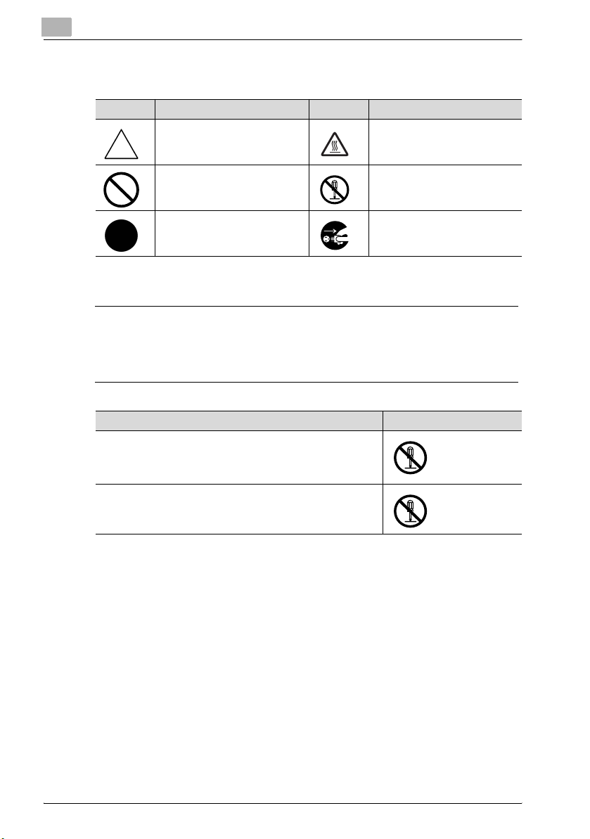
Meaning of Symbols
Symbol Meaning Example Meaning
A triangle indicates a danger
against which you should take
precaution.
A diagonal line indicates a prohibited course of action.
This symbol warns against possible causes of burns.
This symbol warns against dismantling the device.
A solid circle indicates an imperative course of action.
This symbol indicates you must
unplug the device.
Disassemble and modification
7 WARNING
Ignoring this warnings could cause serious injury or even death.
% Do not ignore this safety advices.
Warning Symbol
• Do not attempt to remove the covers and panels which have
been fixed to the product. Some products have a high-voltage part or a laser beam source inside that could cause an
electrical shock or blindness.
• Do not modify this product, as a fire, electrical shock, or
breakdown could result. If the product employs a laser, the
laser beam source could cause blindness.
2-4 C352P
Page 31

Installation and operation precautions
Power cord
7 WARNING
Ignoring this warnings could cause serious injury or even death.
% Do not ignore this safety advices.
Warning Symbol
• Use only the power cord supplied in the package. If a power
cord is not supplied, only use the power cord and plug that
is specified in POWER CORD INSTRUCTION. Failure to use
this cord could result in a fire or electrical shock.
• Use the power cord supplied in the package only for this machine and NEVER use it for any other product. Failure to observe this precaution could result in a fire or electrical shock.
• Do not scratch, abrade, place a heavy object on, heat, twist,
bend, pull on, or damage the power cord. Use of a damaged
power cord (exposed core wire, broken wire, etc.) could result in a fire or breakdown.
Should any of these conditions be found, immediately turn
OFF the power switch, unplug the power cord from the power outlet, and then call your authorized service representative.
2
C352P 2-5
Page 32

2
Installation and operation precautions
Power source
7 WARNING
Ignoring this warnings could cause serious injury or even death.
% Do not ignore this safety advices.
Warning Symbol
• Use only the specified power source voltage. Failure to do
that could result in a fire or electrical shock.
• Connect power plug directly into wall outlet having the same
configuration as the plug. Use of an adapter leads to the
product connecting to inadequate power supply (voltage,
current capacity, grounding), and may result in fire or shock.
If proper wall outlet is not available, the customer shall ask
qualified electrician for the installation.
• Do not use a multiple outlet adapter nor an extension cord in
principle. Use of an adapter or an extension cord could cause
a fire or electrical shock.
Contact your authorized service representative if an extension cord is required.
• Consult your authorized service representative before connecting other equipment on the same wall outlet. Overload
could result in a fire.
7 CAUTION
Ignoring this cautions could cause injury or damage to property.
% Do not ignore this safety advices.
Caution Symbol
• The outlet must be near the equipment and easily accessible.
Otherwise you can not pull out the power plug when an emergency occurs.
2-6 C352P
Page 33

Installation and operation precautions
Power plug
7 WARNING
Ignoring this warnings could cause serious injury or even death.
% Do not ignore this safety advices.
Warning Symbol
• Do not unplug and plug in the power cord with a wet hand,
as an electrical shock could result.
• Plug the power cord all the way into the power outlet. Failure
to do this could result in a fire or electrical shock.
7 CAUTION
Ignoring this cautions could cause injury or damage to property.
% Do not ignore this safety advices.
2
Caution Symbol
• Do not tug the power cord when unplugging. Pulling on the
power cord could damage the cord, resulting in a fire or electrical shock.
• Remove the power plug from the outlet more than one time a
year and clean the area between the plug terminals. Dust that
accumulates between the plug terminals may cause a fire.
Grounding
7 WARNING
Ignoring this warnings could cause serious injury or even death.
% Do not ignore this safety advices.
Warning Symbol
• Connect the power cord to an electrical outlet that is
equipped with a grounding terminal.
C352P 2-7
Page 34

2
Installation and operation precautions
Installation
7 WARNING
Ignoring this warnings could cause serious injury or even death.
% Do not ignore this safety advices.
Warning Symbol
• Do not place a flower vase or other container that contains
water, or metal clips or other small metallic objects on this
product. Spilled water or metallic objects dropped inside the
product could result in a fire, electrical shock, or breakdown.
Should a piece of metal, water, or any other similar foreign
matter get inside the product, immediately turn OFF the power switch, unplug the power cord from the power outlet, and
then call your authorized service representative.
7 CAUTION
Ignoring this cautions could cause injury or damage to property.
% Do not ignore this safety advices.
Caution Symbol
• After installing this product, mount it on a secure base. If the
unit moves or falls, it may cause personal injury.
• Do not place the product in a dusty place, or a site exposed
to soot or steam, near a kitchen table, bath, or a humidifier.
A fire, electrical shock, or breakdown could result.
• Do not place this product on an unstable or tilted bench, or
in a location subject to a lot of vibration and shock. It could
drop or fall, causing personal injury or mechanical breakdown.
• Do not let any object plug the ventilation holes of this product. Heat could accumulate inside the product, resulting in a
fire or malfunction.
• Do not use flammable sprays, liquids, or gases near this
product, as a fire could result.
2-8 C352P
Page 35

Installation and operation precautions
Ventilation
7 CAUTION
Ignoring this cautions could cause injury or damage to property.
% Do not ignore this safety advices.
Caution Symbol
• Always use this product in a well ventilated location. Operating the product in a poorly ventilated room for an extended
period of time could injure your health. Ventilate the room at
regular intervals.
Actions in response to troubles
7 WARNING
Ignoring this warnings could cause serious injury or even death.
% Do not ignore this safety advices.
2
Warning Symbol
• Do not keep using this product, if this product becomes inordinately hot or emits smoke, or unusual odor or noise. Immediately turn OFF the power switch, unplug the power cord
from the power outlet, and then call your authorized service
representative. If you keep on using it as is, a fire or electrical
shock could result.
• Do not keep using this product, if this product has been
dropped or its cover damaged. Immediately turn OFF the
power switch, unplug the power cord from the power outlet,
and then call your authorized service representative. If you
keep on using it as is, a fire or electrical shock could result.
C352P 2-9
Page 36

2
Installation and operation precautions
7 CAUTION
Ignoring this cautions could cause injury or damage to property.
% Do not ignore this safety advices.
Caution Symbol
• The inside of this product has areas subject to high temperature, which may cause burns.
When checking the inside of the unit for malfunctions such as
a paper misfeed, do not touch the locations (around the fusing unit, etc.) which are indicated by a “Caution HOT” caution
label.
Consumables
7 WARNING
Ignoring this warnings could cause serious injury or even death.
% Do not ignore this safety advices.
Warning Symbol
• Do not throw the toner cartridge or toner into an open flame.
The hot toner may scatter and cause burns or other damage.
7 CAUTION
Ignoring this cautions could cause injury or damage to property.
% Do not ignore this safety advices.
Caution Symbol
• Do not leave a toner unit or drum unit in a place within easy
reach of children. Licking or ingesting any of these things
could injure your health.
• Do not store toner units and PC drum units near a floppy disk
or watch that are susceptible to magnetism. They could
cause these products to malfunction.
2-10 C352P
Page 37

Installation and operation precautions
When moving the machine
7 CAUTION
Ignoring this cautions could cause injury or damage to property.
% Do not ignore this safety advices.
Caution Symbol
• Whenever moving this product, be sure to disconnect the
power cord and other cables. Failure to do this could damage
the cord or cable, resulting in a fire, electrical shock, or
breakdown.
• When moving this product, always hold it by the locations
specified in the user manual or other documents. If the unit
falls it may cause severe personal injury. The product may
also be damaged or malfunction.
Before successive holidays
7 CAUTION
Ignoring this cautions could cause injury or damage to property.
% Do not ignore this safety advices.
2
Caution Symbol
• Unplug the product when you will not use the product for
long periods of time.
C352P 2-11
Page 38

2
2.2 Regulation notices
CE Marking (Declaration of conformity) for users of the European Union (EU)
This product complies with the following EU directives:
89/336/EEC, 73/23/EEC and 93/68/EEC directives.
This declaration is valid for the area of the European Union.
This device must be used with a shielded network (10 Base-T/100 Base-TX)
cable and a shielded parallel cable. The use of non-shielded cables is likely
to result in interference with radio communications and is prohibited under
CISPR rules and local rules.
USER INSTRUCTIONS FCC PART 15 - RADIO FREQUENCY DEVICES (for U.S.A. users)
This equipment has been tested and found to comply with the limits for a
Class A digital device, pursuant to Part 15 of the FCC Rules.
These limits are designed to provide reasonable protection against harmful
interference when the equipment is operated in a commercial environment.
This equipment generates, uses and can radiate radio frequency energy and,
if not installed and used in accordance with the instruction manual, may
cause harmful interference to radio communications. Operation of this
equipment in a residential area is likely to cause harmful interference in which
case the user will be required to correct the interference at his own expense.
Installation and operation precautions
7 WARNING
The design and production of this unit conform to FCC regulations, and
any changes or modifications must be registered with the FCC and are
subject to FCC control.
Any changes made by the purchaser or user without first contacting the
manufacturer will be subject to penalty under FCC regulations.
% This device must be used with a shielded network (10 Base-T/100
Base-TX) cable and a shielded parallel cable. The use of non-shielded
cables is likely to result in interference with radio communications and
is prohibited under FCC rules.
2-12 C352P
Page 39

Installation and operation precautions
INTERFERENCE-CAUSING EQUIPMENT STANDARD (ICES-003 ISSUE 4) (for Canada users)
This Class A digital apparatus complies with Canadian ICES-003.
Cet appareil numérique de la classe A est conforme à la norme NMB-003 du
Canada.
For users in countries not subject to class B regulations
7 WARNING
Interference with radio communications.
% This is a Class A product. In a domestic environment this product may
cause radio interference in which case the user may be required to take
adequate measures.
% This device must be used with a shielded network (10 Base-T/100
Base-TX) cable and a shielded parallel cable. The use of non-shielded
cables is likely to result in interference with radio communications and
is prohibited under CISPR rules and local rules.
Laser safety
This is a digital machine which operates using a laser. There is no possibility
of danger from the laser provided the machine is operated according to the
instructions in this manual.
Since radiation emitted by the laser is completely confined within protective
housing, the laser beam cannot escape from the machine during any phase
of user operation.
This machine is certified as a Class 1 laser product: This means the machine
does not produce hazardous laser radiation.
2
C352P 2-13
Page 40

2
Installation and operation precautions
Internal laser radiation
Specification
Maximum Average Radiation Power
Wavelength 775-800 nm
11.6 μW at the laser aperture of the print head unit
7 WARNING
This product employs a Class 3B laser diode that emits an invisible laser
beam.
% The laser diode and the scanning polygon mirror are incorporated in
the print head unit.
% The print head unit is NOT A FIELD SERVICE ITEM:
Therefore, the print head unit should not be opened under any circumstances.
Laser aperture
of the print head
unit
Print head
2-14 C352P
Page 41

Installation and operation precautions
CDRH regulations
This machine is certified as a Class 1 Laser product under Radiation Performance Standard according to the Food, Drug and Cosmetic Act of 1990.
Compliance is mandatory for Laser products marketed in the United States
and is reported to the Center for Devices and Radiological Health (CDRH) of
the U.S. Food and Drug Administration of the U.S. Department of Health and
Human Services (DHHS). This means that the device does not produce hazardous laser radiation.
The label shown on page 2-18 indicates compliance with the CDRH regulations and must be attached to laser products marketed in the United States.
7 CAUTION
Use of controls, adjustments or performance of procedures other than
those specified in this manual may result in hazardous radiation exposure.
% This is a semiconductor laser. The maximum power of the laser diode
is 10 mW and the wavelength is 775-800 nm.
2
C352P 2-15
Page 42

2
Installation and operation precautions
For European users
7 CAUTION
Use of controls, adjustments or performance of procedures other than
those specified in this manual may result in hazardous radiation exposure.
% This is a semiconductor laser. The maximum power of the laser diode
is 10 mW and the wavelength is 775-800 nm.
For Denmark users
7 ADVARSEL
Usynlig laserstråling ved åbning, når sikkerhedsafbrydere er ude af
funktion.
% Undgå udsættelse for stråling. Klasse 1 laser produkt der opfylder
IEC60825 sikkerheds kravene.
Dette er en halvlederlaser. Laserdiodens højeste styrke er 10 mW og
bølgelængden er 775-800 nm.
For Finland, Sweden users
LOUKAN 1 LASERLAITE
KLASS 1 LASER APPARAT
7 VAROITUS
Tämä on puolijohdelaser.
% Laitteen Käyttäminen muulla kuin tässä käyttöohjeessa mainitulla tav-
alla saattaa altistaa käyttäjän turvallisuusluokan 1 ylittävälle näkymättömälle lasersäteilylle.
Tämä on puolijohdelaser. Laserdiodin sunrin teho on 10 mW ja aallonpituus
on 775-800 nm.
2-16 C352P
Page 43

Installation and operation precautions
7 VARNING
Det här är en halvledarlaser.
% Om apparaten används på annat sätt än i denna bruksanvisning spe-
cificerats, kan användaren utsättas för osynlig laserstrålning, som
överskrider gränsen för laserklass 1.
Det här är en halvledarlaser. Den maximala effekten för laserdioden är 10 mW
och våglängden är 775-800 nm.
7 VAROITUS
Avattaessa ja suojalukitus ohitettaessa olet alttiina näkymättömälle lasersäteilylle.
% Älä katso säteeseen.
7 VARNING
Osynlig laserstrålning när denna del är öppnad och spärren är urkopplad.
% Betrakta ej strålen.
2
For Norway users
7 ADVARSEL!
Dette en halvleder laser.
% Dersom apparatet brukes på annen måte enn spesifisert i denne bruk-
sanvisning, kan brukeren utsettes for unsynlig laserstråling som overskrider grensen for laser klass 1.
Dette en halvleder laser. Maksimal effekt till laserdiode er 10 mW og bølgelengde er 775-800 nm.
C352P 2-17
Page 44

2
Installation and operation precautions
Laser safety label
A laser safety label is attached to the outside of the machine, as shown below.
2-18 C352P
Page 45

Installation and operation precautions
Ozone release
7 CAUTION
Locate the Machine in a Well Ventilated Room
% A negligible amount of ozone is generated during normal operation of
this machine. An unpleasant odor may, however, be created in poorly
ventilated rooms during extensive machine operations. For a comfortable, healthy, and safe operating environment, it is recommended that
the room well ventilated.
7 ATTENTION
Une quantité d’ozone négligable est dégagée pendant le fonctionnement de l’appareil quand celui-ci est utilisé normalement.
Cependant, une odeur désagréable peut être ressentie dans les pièces dont
l’aération est insuffisante et lorsque une utilisation prolongée de l’appareil
est effectuée. Pour avoir la certitude de travailler dans un environnement réunissant des conditions de confort, santé et de sécurité, il est préférable de
bien aérer la pièce ou se trouve l’appareil.
% Placer l’appareil dans une pièce largement ventilée.
2
Acoustic noise (for European users only)
Maschinenlärminformations-Verordnung 3. GPSGV: Der höchste
Schalldruckpegel beträgt 70 dB(A) oder weniger gemäß EN ISO 7779.
For EU member states only
This symbol means: Do not dispose of this
product together with your household
waste!
Please refer to the information of your local
community or contact our dealers regrading the proper handling of end-of-life electric and electronic equipments. Recycling
of this product will help to conserve natural
resources and prevent potential negative consequences for the environment
and human health caused by inappropriate waste handling.
C352P 2-19
Page 46

2
Installation and operation precautions
2.3 Caution notations and labels
Safety precaution notations and labels appear on this machine at the following positions.
Be very careful that an accident does not occur when operations such as removing paper misfeeds are performed.
WARNING
Do not burn used
toner cartridges.
Toner expelled from
the fire is dangerous.
CAUTION
Do not alter or remove
any covers or panels
attached to this
machine, otherwise
you may be exposed
to laser radiation.
WARNING
Do not position the used
waste-toner box so that
it is standing on end or
tilted, otherwise toner
may spill.
CAUTION
Do not burn the used
waste-toner box.
Toner expelled from
the fire is dangerous.
WARNING
Do not burn used
imaging units. Toner
expelled from the fire
is dangerous.
CAUTION
The area around the
fusing unit is extremely
hot. Touching any part
other than those
indicated may result in
burns.
2-20 C352P
Page 47

Installation and operation precautions
2.4 Space requirements
To ensure that machine operation, consumables replenishing, part replacement, and regular maintenance can easily be performed, adhere to the recommended space requirements detailed below.
2
190
(7-1/2)
437
(17-1/4)
1212
(47-3/4)
C352P+FS-514+PC-403+SD-503+OT-601
341
(13-1/2)
1208 (47-1/2)
712
(28)
Unit: mm (inch)
2
Reminder
Be sure to allow a clearance of 100 mm (4 inch) or more at the back of
this machine for the ventilation duct.
100
(4)
C352P 2-21
Page 48

2
2.5 Operation precautions
To ensure the optimum performance of this machine, observe the precautions described below.
Power source
The power source requirements are as follows.
- Voltage fluctuation: Maximum ± 10% (at 110 V/120 to 127 V/220 to
240 V AC)
- Frequency fluctuation: Maximum ± 3 Hz (at 50 Hz/60 Hz)
– Use a power source with as little voltage or frequency fluctuations as
possible.
Operating environment
The environmental requirements for correct operation of the machine are as
follows.
- Temperature: 10°C (50°F) to 30°C (86°F) with fluctuations of no more than
10°C (18°F) within an hour
- Humidity: 15% to 85% with fluctuations of no more than 10% within an
hour
Storage of printed pages
To store printed pages, follow the recommendation listed below.
- printed pages that are to be kept for a long time should be kept where
they are not exposed to light in order to prevent them from fading.
- Adhesive that contains solvent (e.g., spray glue) may dissolve the toner
on printed pages.
- Color printed pages have a thicker layer of toner than normal black-and-
white printed pages. Therefore, when a color printed page is folded, the
toner at the fold may peel off.
Installation and operation precautions
2-22 C352P
Page 49

Installation and operation precautions
2.6 Part names and their functions
Options
8
9
7
6
5
2
1
234
* In order to maintain the functionality and quality of the machine, be sure to
use the paper feed cabinet when installing the machine on the floor.
C352P 2-23
Page 50

2
Installation and operation precautions
No. Part Name Description
1 Main unit The data sent from the computer is printed.
2 Paper Feed Cabinet PC-103 The top tray can be loaded with up to 500 sheets of
3 Paper Feed Cabinet PC-203 Both the top and bottom trays can each be loaded
4 Paper Feed Cabinet PC-403 Can be loaded with up to 2,500 sheets of paper
5 Finisher FS-514 Feeds out finished printed pages. The “Sort” set-
6 Output Tray OT-601 Print output tray installed onto the finisher and used
7 Punch Kit PK-510 Allows hole punching to be used if installed onto
8 Mailbin Kit MT-501 Installed onto the finisher to divide printed pages
9 Saddle Stitcher SD-503 Installed onto the finisher so that prints can be
10 Dehumidifer Heater 1C* Installed in the paper feed cabinet to prevent hu-
11 Mount Kit MK-706* Required to mount the local interface kit
12 Local Interface Kit EK-702* Used for making a local connection between this
13 Security Kit SC-503* Installed to encode the data saved on the hard disk
14 Hard Disk Drive HD-501* Operations using the “Secured Print” and “Save in
* Parts marked with an asterisk (*) are internal options and therefore are not shown in the illustra-
tion.
Referred to as the “machine”, the “main unit”, or
the “C352P” throughout the manual.
paper, and the bottom tray can be used as storage.
Referred to as the “single paper feed cabinet”
throughout the manual.
with up to 500 sheets of paper.
Referred to as the “double paper feed cabinet”
throughout the manual.
Referred to as the “LCT” throughout the manual.
ting (separating by copy set), “Group” setting (separating by page), and Staple settings (corner
stapling and two-point stapling) are available.
Referred to as the “finisher” throughout the manual.
for separating printed pages
Referred to as the “optional finishing tray” throughout the manual.
finisher
Referred to as the “punch kit” throughout the manual.
and feed them into the appropriate tray assigned to
a specific individual or group
Referred to as the “mailbin” throughout the manual.
bound or folded at the center
Referred to as the “saddle stitcher” throughout the
manual.
midity from collecting in the paper
machine and the computer
so that the hard disk can be used more safely.
User Box” settings can be used if the hard disk
drive is installed.
Referred to as the “HDD” throughout the manual.
2-24 C352P
Page 51

Installation and operation precautions
2
Reminder
In order to maintain the functionality and quality of the machine, be sure
to use the paper feed cabinet when installing the machine on the floor.
2
C352P 2-25
Page 52

2
Installation and operation precautions
Outside of machine
9
8
1
7
6
5
4
3
2
* The illustration above shows the main unit with the optional LCT installed.
2-26 C352P
Page 53

Installation and operation precautions
No. Part Name Description
1 ADU Turns over the paper for double-sided printing
2 Bypass tray Used when printing onto paper with a size not load-
3 LCT Can be loaded with up to 2,500 sheets of normal
4 Tray release button Pressed in order to pull out the paper tray for the
5 Tray 2 Can be loaded with up to 500 sheets of normal pa-
6 Tray 1 Can be loaded with up to 250 sheets of normal pa-
7 Front door Opened when replacing a toner cartridge. (See
8 Power switch Used to turn the machine on and off (See p. 2-39)
9 Finishing tray Collects printed pages
ed into a paper tray or onto thick paper, OHP transparencies, postcards, envelopes or labels
Holds up to 100 sheets of normal paper, 20 sheets
of thick paper, OHP transparencies, postcards or
label sheets, or 10 envelopes. (See p. 6-19.)
paper
LCT
per (See p. 6-15.)
per, can be set to different paper sizes, and can be
loaded with up to 20 sheets of thick paper, OHP
transparencies, postcards, labels, or envelopes
(See p. 6-11.)
p. 7-5.)
2
C352P 2-27
Page 54

2
Installation and operation precautions
19
10
11
12
13
18
14
17
15
16
* The illustration above shows the main unit with the optional double paper
feed cabinet installed.
2-28 C352P
Page 55

Installation and operation precautions
No. Part Name Description
10 ADU release lever Used to open the ADU door when clearing paper
11 ADU door Opened when clearing paper misfeeds within the
12 Upper right-side door release le-
ver
13 Center right-side door Opened when clearing paper misfeeds from the
14 Center right-side door release le-
ver
15 Lower right-side door Opened when clearing paper misfeeds from the
16 Lower right-side door release le-
ver
17 Tray 4/storage tray Used for storage when the single paper feed cabi-
18 Tray 3 Can be loaded with up to 500 sheets of normal pa-
19 Control panel Used to specify the various settings (See p. 2-38.)
misfeeds
ADU
Used to open the upper right-side door
tray 2
Used to open the center right-side door
tray 3 or 4 or from the LCT
Used to open the lower right-side door when clearing paper misfeeds
net is installed
Can be loaded with up to 500 sheets of normal paper when the double paper feed cabinet is installed
(See p. 6-15.)
per (See p. 6-15.)
2
C352P 2-29
Page 56

2
Installation and operation precautions
20
25
21
24
23
27
26
28
22
2-30 C352P
Page 57

Installation and operation precautions
No. Part Name Description
20 Filter 2 Collects the toner dust generated in the machine
21 Power connector Used for connecting the power cord
22 Dehumidifier heater power switch Used to turn dehumidifier heater on and off.
23 IEEE1284 port (type C) Used for connecting the parallel cable from the
24 USB port (type B)
USB 2.0/1.1-compliant
25 Network connector
(10 Base-T/100 Base -TX)
26 Ozone filter Collects the ozone generated in the machine
27 Finisher connector Used for connecting the finisher hookup cord
28 Filter 1 Collects the toner dust generated in the machine
Turning on the dehumidifier heater reduces moisture in the paper. This switch is used when the optional dehumidifier heater is installed.
Use the dehumidifier heater when the optional single paper feed cabinet, double paper feed cabinet
and LCT are installed.
computer
Used for connecting a USB cable from the computer
Used for connecting the network cable when this
machine is used for network printing
2
C352P 2-31
Page 58

2
Inside of machine
13
12
11
Installation and operation precautions
1
2
3
10
2
9
8
4
5
6
7
2-32 C352P
Page 59

Installation and operation precautions
No. Part Name Description
1 Fusing unit cover Opened when clearing paper misfeeds in the fusing
2 Release levers Used when clearing paper misfeeds in the fusing
3 Fusing unit cover release button Pressed to open the fusing unit cover
4 Upper right-side door Opened when clearing paper misfeeds from inside
5 Unlocking knob Used when removing the imaging units
6 Imaging unit Creates the print image
7 Charger-cleaning tool Used to clean the electrostatic charger wire, for ex-
8 Print head glass cleaning tool Used to clean the surface of the print head glass,
9 Waste toner box Collects used waste toner
10 Waste toner box release lever Used when removing the waste toner box
11 Total counter Shows the total number of pages that have been
12 Locking tab Used when removing the toner cartridges
13 Toner cartridges There are four toner cartridges: cyan (C), magenta
unit
unit.
the main unit
ample, when incorrect prints are produced (See
p. 8-4.)
for example, when replacing the imaging unit
printed
(M), yellow (Y) and black (K). The combination of the
four toners generates full-color images.
2
C352P 2-33
Page 60

2
Installation and operation precautions
Saddle stitcher SD-503/mailbin kit MT-501
4
2
1
3
5
Saddle stitcher SD-503
No. Part name Description
1 Print output tray Collects printed pages.
2 Misfeed-clearing door Opened when clearing paper misfeeds within
the finisher
Mailbin kit MT-501
No. Part name Description
3 Mailbins Collects printed pages
4 Misfeed-clearing door Opened when clearing paper misfeeds
5 Lever [FN7] Opened when clearing paper misfeeds
2-34 C352P
Page 61

Installation and operation precautions
Finisher FS-514/output tray OT-601/punch kit PK-510
1
12
2
2
34 5 6 7
89101112
C352P 2-35
Page 62

2
Installation and operation precautions
Finisher FS-514
No. Part name Description
1 Output tray 1 Collects prints that are fed out
2 Output tray 2 Collects prints that are fed out
3 Dial [FN6] Turned when clearing paper misfeeds within the
4 Dial [FN5] Turned when clearing paper misfeeds within the
5 Dial [FN4] Turned when clearing paper misfeeds within the
6 Dial [FN2] Turned when clearing paper misfeeds within the
7 Lever [FN1] Raised when clearing paper misfeeds within the
8 Hole-punch waste container Removed when emptying hole-punch waste
9 Lever [FN3] Lowered when clearing paper misfeeds within
10 Stapler Moved to the front when clearing jammed sta-
11 Staple cartridge holder Removed from the stapler when replacing the
12 Dial Turned to move the stapler to the front when
finisher
finisher
finisher
finisher
finisher
that has accumulated from using the punch settings
the finisher
ples
staple cartridge or clearing jammed staples
clearing jammed staples
Output tray OT-601
No. Part name Description
12 Optional output tray Collects prints
Punch kit PK-510
No. Part name Description
13 Punch Kit* Punches holes for filing printed pages when
* Parts marked with an asterisk (*) are installed within the finisher and therefore are not shown in
the illustration.
punch kit is installed onto finisher
2-36 C352P
Page 63

Installation and operation precautions
Precautions for using the finisher:
- Do not place objects on top of the saddle stitcher or mailbin kit.
- Do not place objects below the output trays of the finisher.
2
C352P 2-37
Page 64

2
Installation and operation precautions
Control panel
12
3
456
No. Part Name Description
1 Ready indicator Lights up when printing is possible and flashes
2 Error indicator Lights up when an error occurs.
3 [Cancel] key Press to cancel printing and other operations.
4 [Menu/Select] key Press to display the menu and select settings.
5 Cursor keys Press to change the menu and to enter values.
6 Display panel Displays various screens and messages.
when data is being received.
2-38 C352P
Page 65

Installation and operation precautions
2.7 Basic operations
Turning on the machine
1 Set the power switch to [ n ].
2 Check that the control panel is turned on.
!
Detail
When the machine is turned on, the printer starts up and the message
“Now warming-up.” appears. After the message “Ready to print.” appears and the Ready indicator lights up, a print job can be received.
The default settings, which are those that are selected immediately after
the machine is turned on, can be changed. For details, refer to “Control
panel” on page 5-3.
2
The factory default settings are the settings that were selected when this
machine was sent from the factory.
2
Note
The machine takes about 72 seconds to warm up at normal room temperature (23°C).
C352P 2-39
Page 66

2
Installation and operation precautions
Turning off the machine
% Set the power switch to [o].
2
Reminder
When the power switch is turned off, then on again, wait at least 10 seconds to turn it on after turning it off. If there is no wait period between
turning the power switch off, then on again, the machine may not function
properly.
Do not turn off the machine with the power switch while it is making printing, otherwise a paper misfeed may occur.
Do not turn off the machine with the power switch while a queued job or
stored data is waiting to be printed, otherwise the jobs will be deleted.
!
Detail
The following are cleared when the power switch is turned off.
Settings that have not been programmed
Jobs queued to be printed.
2-40 C352P
Page 67

Installation and operation precautions
Automatically canceling the settings (automatic panel reset)
If no operation is performed for a specified length of time while settings are
being changed, settings that have not been programmed are cleared and return to their defaults.
This is the automatic panel reset operation.
As the factory default, the automatic panel reset operation is performed after
1 minute.
!
Detail
The length of time until the automatic panel reset operation is performed
and whether or not it is performed can be set from the Utility mode. For
details, refer to “User Setting” on page 5-32.
Automatically conserving energy (Low Power mode)
If no operation is performed for a specified length of time the machine automatically enters a mode where it conserves energy.
This is the Low Power mode.
The machine can receive jobs even while it is in Low Power mode.
As the factory default, the machine enters Low Power mode after 15 minutes.
2
2
Note
When a print job is received, the machine recovers from Low Power
mode and begins printing after it has finished warming up (within 30 seconds at normal room temperature (23°C)).
The Low Power mode can also be canceled by pressing any key in the
control panel.
!
Detail
The length of time until the machine enters Low Power mode can be
changed. For details, refer to “User Setting” on page 5-32.
C352P 2-41
Page 68

2
Installation and operation precautions
Automatically conserving energy (Sleep mode)
If no operation is performed for a specified length of time, the machine automatically enters a mode where it conserves energy.
Although the machine conserves more energy in Sleep mode than in Low
Power mode, the machine must warm up when Sleep mode is canceled to
begin printing again, therefore taking more preparation time than Low Power
mode.
As the factory default, the machine enters Sleep mode after 15 minutes.
2
Note
When a print job is received, the machine recovers from Low Power
mode and begins printing after it has finished warming up (within 72 seconds at normal room temperature (23°C)).
The Sleep mode can also be canceled by pressing any key in the control
panel.
!
Detail
The length of time until the machine enters Sleep mode can be changed.
For details, refer to “User Setting” on page 5-32.
2-42 C352P
Page 69

Installation and operation precautions
Power supply
Be sure to turn off the machine if it is not to be used for a long period of time,
for example, overnight.
In order to ensure that no energy is being consumed, unplug the machine.
2
C352P 2-43
Page 70

2
2.8 Connecting to a computer
Compatible interfaces
The various interfaces that can be used to connect this printer to a computer
are described below.
Ethernet interface
Connect when using this printing system as a network printer.
Supports 10Base-T and 100Base-TX standards. In addition, the Ethernet interface supports the TCP/IP (LDP/LPR, peer-to-peer), IPX/SPX (NetWare),
and AppleTalk (EtherTalk) protocols.
Parallel interface (optional)
Connect when using this printing system as a local printer.
A computer running Windows and an IEEE 1284 parallel cable are required
for connection. Use a parallel cable that uses a terminal with an Amphenol
36-pin male connector.
The parallel interface supports the compatible, nibble, and ECP modes.
USB interface (optional)
Connect when using this printing system as a USB printer.
The USB interface can be connected to a computer running Windows. A
USB cable is required for connection. Use a type A (4 pin, male) or type B (4
pin, male) USB cable. A USB cable measuring 3 meters or less is recommended.
Installation and operation precautions
2
Note
The USB and parallel interfaces cannot be used as the same time.
Change the setting in the “I/F Setting” menu of the “Admin. Setting”
menu.
2-44 C352P
Page 71

Installation and operation precautions
Connection diagram
The printer cables can be connected to each port at the back of this machine.
USB port
2
Ethernet
(10Base-T or
100 Base-TX)
Parallel port
C352P 2-45
Page 72

2
Installation and operation precautions
2-46 C352P
Page 73

3
Setting up the printer
driver
Page 74

Page 75

Setting up the printer driver
3 Setting up the printer driver
3.1 About the provided printer drivers
Printer drivers and supported operating systems
In order to use this printing system, the printer driver must be installed. The
printer driver is a program that controls the processing of data for output. Install the printer driver onto the computer from the provided CD-ROM.
The printer drivers included on the CD and the supported computer operating systems are listed below. Install the required printer driver.
- PCL (PCL XL) Konica Minolta Driver:
Windows 98SE, Windows Me, Windows NT 4.0 (SP6a), Windows 2000
Professional (SP4 or later), Windows XP Home Edition, Windows XP Professional (SP2 or later), and Windows Server 2003
- PostScript 3 Emulation Konica Minolta:
Windows NT 4.0 (SP6a), Windows 2000 Professional (SP4 or later), Windows XP Home Edition/Professional (SP2 or later), and Windows Server
2003
- PostScript 3 Emulation PPD Driver
Windows 98SE, Windows Me, Mac OS 9.2 or later, Mac OS X 10.2, Mac
OS X 10.3, and Mac OS X 10.4
3
2
Note
The User Software CD-ROM contains the PCL printer driver, and the
PostScript Printer Driver CD-ROM contains the PostScript driver.
C352P 3-3
Page 76

3
Setting up the printer driver
System requirements
Check that the computer being connected meets the following conditions.
Windows
- Operating System:
Windows 98SE, Windows Me, Windows NT 4.0 (SP6a or later), Windows
2000 Professional (SP4 or later), Windows XP Home Edition (SP2 or later), Windows XP Professional (SP2 or later), or Windows Server 2003
- Processor: Pentium or higher
- Memory: Capacity recommended for the operating system
With sufficient memory resources in the operating system and application being used
- Drive: CD-ROM
- Web Browser (when using PageScope Web Connection):
Microsoft Internet Explorer 6 or later recommended (JavaScript enabled,
Cookies enabled)
Microsoft XML Parser (MSXML) 3.X must be installed when using Internet
Explorer 5.x.
Netscape Navigator 7.02 or later (JavaScript enabled, Cookies enabled)
Macromedia
Macintosh
- Operating System: Mac OS 9.2, Mac OS X 10.2, Mac OS X 10.3, or Mac
OS X 10.4
- Processor: PowerPC
- Memory: Capacity recommended for the operating system
- Drive: CD-ROM
- Web Browser (when using PageScope Web Connection):
Netscape Navigator 7.02 or later (JavaScript enabled, Cookies enabled)
®
Flash® (version 7.0 or later plugin) required
3-4 C352P
Page 77

Setting up the printer driver
Setting up the system
In order to use this printing system, it must first be set up.
Setup consists of connecting this machine to a computer and installing the
printer driver onto the computer being used.
Setup the printing system as described below.
1 Connect this machine to a computer. (Refer to “Connecting to a com-
puter” on page 2-44.)
2 Install the printer driver. (Refer to “Installing the printer driver” on
page 3-6.)
– Installation of the printer driver may differ depending on the con-
nection method used with this machine in addition to the operating
system of the computer and the type of printer driver being used.
– To update an existing printer driver, delete the existing printer driver
first. For details, refer to “Uninstalling the printer driver” on
page 3-17.
3 When using a network connection, set up the network. (Refer to “Set-
ting up network printing” on page 3-28.)
– As necessary, set the interface timeout settings and parallel inter-
face mode (Compatible, Nibble, or ECP) in the I/F Setting menu
from the control panel. When using a parallel or USB port, you must
select the port being used. For details, refer to “Admin. Setting” on
page 5-38.
3
4 Check the setup by printing a test page. (Refer to “Test printing” on
page 3-26.)
5 Install the screen fonts.
– The User Software CD-ROM and PostScript Printer Driver CD-ROM
contain the Latin TrueType fonts as the screen fonts.
– Install the screen fronts after adding the operating system standard
fonts. For details, refer to Help of the operating system.
– The screen fonts are located in the Screenfont or Screenfonts folder
on the CD-ROM.
– To install the Macintosh fonts, install the fonts after decompressing
them.
C352P 3-5
Page 78

3
3.2 Installing the printer driver
When used with Windows
The installation procedure of the Windows printer driver differs depending on
how this machine is connected to the computer and depending on which
printer driver is used. The installation method also differs depending on the
version of Windows that you are using. Refer to the pages indicated below
for the appropriate procedure for installing the printer driver on your computer.
PostScript/PCL (All connection methods):
PostScript/PCL (Network connection):
To install the printer driver using the Add Printer Wizard, refer to “Installing
the printer driver using the Add Printer Wizard” on page 3-8, “For Windows
98SE/Me/2000/NT 4.0” on page 3-10, or “For Windows XP/Server 2003” on
page 3-8.
PostScript/PCL (Parallel connection):
To install the printer driver using Plug and Play, refer to “Installing the printer
driver using Plug and Play” on page 3-12, “For Windows 98SE” on
page 3-12, “For Windows Me/2000” on page 3-13, or “For Windows XP/
Server 2003” on page 3-15.
To install the printer driver using the Add Printer Wizard, refer to “Installing
the printer driver using the Add Printer Wizard” on page 3-8, “For Windows
98SE/Me/2000/NT 4.0” on page 3-10, or “For Windows XP/Server 2003” on
page 3-8.
PostScript/PCL (USB connection):
To install the printer driver using Plug and Play, refer to “Installing the printer
driver using Plug and Play” on page 3-12, “For Windows 98SE” on
page 3-12, “For Windows Me/2000” on page 3-13, or “For Windows XP/
Server 2003” on page 3-15.
Setting up the printer driver
2
Note
For details on installing the printer driver in a network environment, refer
to “Setting up network printing” on page 3-28. Because it is necessary to
specify other network settings in advance when installing the printer driver using a network connection, install it using a local connection at this
time.
3-6 C352P
Page 79

Setting up the printer driver
2
Note
To install the printer driver on a computer running Windows XP, Windows
Server 2003, Windows 2000, or Windows NT 4.0, log on with a user name
registered with Administrator privileges.
To connect this machine to a computer using a parallel connection or a
USB connection, the optional local interface kit is required.
3
C352P 3-7
Page 80

3
Setting up the printer driver
Installing the printer driver using the Add Printer Wizard
2
Note
For IPP printing, it is not necessary to install the printer driver at this time
since IPP printing setup is performed when the printer driver is installed.
For further details on IPP printing, refer to “IPP printing (Windows 2000/
XP/Server 2003)” on page 3-47.
2
Note
For details on installing the printer driver in a network environment, refer
to “Setting up network printing” on page 3-28. Because it is necessary to
specify other network settings in advance when installing the printer driver using a network connection, install it using a local connection at this
time.
For Windows XP/Server 2003
1 Insert the Windows printer driver CD-ROM into the computer’s CD-
ROM drive.
– Konica Minolta PCL driver: User Software CD-ROM
– Konica Minolta PostScript driver: PostScript Printer Driver CD-
ROM
2 Click the [Start] button, and then click “Printers and Faxes”.
– If “Printers and Faxes” does not appear in the Start menu, click
Control Panel in the Start menu, click “Printers and Other Hardware”, and then click “Printers and Faxes”.
3 For Windows XP, click “Add a printer” on the “Printer Tasks” menu.
– For Windows Server 2003, double-click the “Add Printer” icon.
The Add Printer Wizard starts up.
4 Click the [Next] button.
5 Select “Local printer attached to this computer”, and then click the
[Next] button.
– Clear the “Automatically detect and install my Plug and Play print-
er” check box.
3-8 C352P
Page 81

Setting up the printer driver
6 The Select Printer Port dialog box appears. Select “LPT1” here, and
then click the [Next] button.
7 Click the [Have Disk] button.
8 Click the [Browse] button.
9 Specify the folder on the CD-ROM that contains the printer driver for
the operating system being used, and then click the [OK] button.
– Konica Minolta PCL driver: Folder at Driver\Drivers\bizhubC352 on
the User Software CD-ROM
– Konica Minolta PostScript driver: Folder at Driver\Drivers on the
PostScript Printer Driver CD-ROM
10 Click the [OK] button.
The “Printers” list appears.
11 Click the [Next] button.
12 Follow the on-screen instructions.
– When the Digital Signature message appears, click the [Continue]
button.
– When using a network connection, perform a test print after the net-
work settings have been specified.
3
13 When installation is complete, make sure that the icon of the installed
printer appears in the Printers and Faxes window.
14 Remove the CD-ROM from the CD-ROM drive.
This completes the printer driver installation.
C352P 3-9
Page 82

3
Setting up the printer driver
For Windows 98SE/Me/2000/NT 4.0
1 Insert the Windows printer driver CD-ROM into the computer’s CD-
ROM drive.
– Konica Minolta PCL driver: User Software CD-ROM
– Konica Minolta PostScript driver: PostScript Printer Driver CD-
ROM
2 Click the [Start] button, point to “Settings”, and then click “Printers”.
The Printers window appears.
3 Double-click the “Add Printer” icon.
The Add Printer Wizard starts up.
4 Follow the on-screen instructions.
5 On the screen for selecting the printer connection, select “Local Print-
er”.
6 Click the [Next] button.
7 Click the [Have Disk] button.
8 Click the [Browse] button.
9 Specify the folder on the CD-ROM that contains the printer driver for
the operating system being used, and then click the [OK] button.
– For Windows 98SE/Me
Konica Minolta PCL driver: Folder at Driver\Drivers\bizhubC352 on
the User Software CD-ROM
PostScript PPD driver: Folder at Driver\PS-PPD on the PostScript
Printer Driver CD-ROM
– For Windows 2000
Konica Minolta PCL driver: Folder at Driver\Drivers\bizhubC352 on
the User Software CD-ROM
Konica Minolta PostScript driver: Folder at Driver\Drivers on the
PostScript Printer Driver CD-ROM
– For Windows NT 4.0
Konica Minolta PCL driver: Folder at Driver\Drivers\bizhubC352 on
the User Software CD-ROM
Konica Minolta PostScript driver: Folder at Driver\Drivers on the
PostScript Printer Driver CD-ROM
3-10 C352P
Page 83

Setting up the printer driver
10 Click the [OK] button.
The “Printers” list appears.
11 Click the [Next] button.
12 Specify the connection port. Select “LPT1” here.
13 Follow the on-screen instructions.
– When using a network connection, perform a test print after the net-
work settings have been specified.
14 When installation is complete, make sure that the icon of the installed
printer appears in the Printers window.
15 Remove the CD-ROM from the CD-ROM drive.
This completes the printer driver installation.
3
C352P 3-11
Page 84

3
Setting up the printer driver
Installing the printer driver using Plug and Play
For Windows 98SE
1 After using a parallel cable or a USB cable to connect this machine to
a computer, turn on the computer.
– Do not disconnect or connect the cable while the computer is start-
ing up.
2 Insert the Windows printer driver CD-ROM into the computer’s CD-
ROM drive.
– Konica Minolta PCL driver: User Software CD-ROM
– Konica Minolta PostScript driver: PostScript Printer Driver CD-
ROM
3 Turn this machine on.
The Add New Hardware Wizard starts up.
4 Click the [Next] button.
5 Select “Search for the best driver for your device (Recommended)”,
and then click the [Next] button.
6 Select “Specify a location”, and then click the [Browse] button.
7 Specify the folder on the CD-ROM that contains the printer driver for
the operating system being used, and then click the [OK] button.
– Konica Minolta PCL driver: Folder at Driver\Drivers\bizhubC352 on
the User Software CD-ROM
– PostScript PPD driver: Folder at Driver\PS-PPD on the PostScript
Printer Driver CD-ROM
8 Click the [Next] button, and then follow the on-screen instructions.
– With a parallel connection, continue with step 10.
9 The Add New Hardware Wizard dialog box appears again. Repeat
steps 4 through 8.
10 When installation is complete, make sure that the icon of the installed
printer appears in the Printers window.
11 Remove the CD-ROM from the CD-ROM drive.
This completes the printer driver installation.
3-12 C352P
Page 85

Setting up the printer driver
For Windows Me/2000
1 After using a parallel cable or a USB cable to connect this machine to
a computer, turn on the computer.
– Do not disconnect or connect the cable while the computer is start-
ing up.
2 Insert the Windows printer driver CD-ROM into the computer’s CD-
ROM drive.
– Konica Minolta PCL driver: User Software CD-ROM
– Konica Minolta PostScript driver: PostScript Printer Driver CD-
ROM
3 Turn this machine on.
– For Windows Me
The Add New Hardware Wizard starts up.
– For Windows 2000
The Found New Hardware Wizard starts up.
4 Select “Search for a suitable driver for my device (recommended)” (for
Windows Me, select “Automatic search for a better driver (Recommended)”), and then click the [Next] button.
3
5 For Windows 2000, select “Specify a location”, and then click the
[Next] button.
For Windows Me, select “Specify a Location”, and then click the
[Browse] button.
6 Specify the folder on the CD-ROM that contains the printer driver for
the operating system being used, and then click the [OK] button.
Printer drivers that are available:
– For Windows Me
Konica Minolta PCL driver: Folder at Driver\Drivers\bizhubC352 on
the User Software CD-ROM
Postscript PPD: Folder at Driver\PS-PPD on the PostScript Printer
Driver CD-ROM
– For Windows 2000
Konica Minolta PCL driver: Folder at Driver\Drivers\bizhubC352 on
the User Software CD-ROM
Konica Minolta PostScript driver: Folder at Driver\Drivers on the
PostScript Printer Driver CD-ROM
7 Click the [OK] button (for Windows Me, click the [Next] button), and
then follow the on-screen instructions.
C352P 3-13
Page 86

3
Setting up the printer driver
8 Click the [Finish] button.
9 When installation is complete, make sure that the icon of the installed
printer appears in the Printers window.
10 Remove the CD-ROM from the CD-ROM drive.
This completes the printer driver installation.
3-14 C352P
Page 87

Setting up the printer driver
For Windows XP/Server 2003
1 After using a parallel cable or a USB cable to connect this machine to
a computer, turn on the computer.
– Do not disconnect or connect the cable while the computer is start-
ing up.
2 Insert the Windows printer driver CD-ROM into the computer’s CD-
ROM drive.
– Konica Minolta PCL driver: User Software CD-ROM
– Konica Minolta PostScript driver: PostScript Printer Driver CD-
ROM
3 Turn this machine on.
– The Add New Hardware Wizard starts up.
If the Add New Hardware Wizard does not appear, turn this machine off, then on again.
– When the machine is turned off, then on again, wait at least 10 sec-
onds to turn the machine on after turning it off. The machine may
not operate correctly if it is turned on immediately after being turned
off.
4 Select “Install from a list or specific location (Advanced)”, and then
click the [Next] button.
3
5 Under “Search for the best driver in these locations”, select “Include
this location in the search”, and then click the [Browse] button.
6 Specify the folder on the CD-ROM that contains the printer driver for
the operating system being used, and then click the [OK] button.
– Konica Minolta PCL driver: Folder at Driver\Drivers\bizhubC352 on
the User Software CD-ROM
– Konica Minolta PostScript driver: Folder at Driver\Drivers on the
PostScript Printer Driver CD-ROM
7 Click the [Next] button, and then follow the on-screen instructions.
– When the Digital Signature dialog box appears, click the [Continue]
button.
C352P 3-15
Page 88

3
Setting up the printer driver
8 Click the [Finish] button.
9 When installation is complete, make sure that the icon of the installed
printer appears in the Printers and Faxes window.
10 Remove the CD-ROM from the CD-ROM drive.
This completes the printer driver installation.
3-16 C352P
Page 89

Setting up the printer driver
Uninstalling the printer driver
If it becomes necessary to delete the printer driver, for example, when you
want to reinstall the printer driver, follow the procedure below to delete the
driver.
1 For Windows 98SE/Me/2000/NT 4.0, click the [Start] button, point to
“Settings”, and then click “Printers”.
For Windows XP/Server 2003, click the [Start] button, and then click
“Printers and Faxes”.
– If “Printers and Faxes” does not appear in the Start menu, click
Control Panel in the Start menu, click “Printers and Other Hardware”, and then click “Printers and Faxes”.
2 In the Printers window (for Windows XP/Server 2003, Printers and Fax-
es window), select the icon of the printer that you want to delete.
3 Press the [Delete] key on the computer keyboard to delete the printer
driver.
4 Follow the on-screen instructions.
– When the printer driver has been deleted, the printer icon will dis-
appear from the Printers window (for Windows XP/Server 2003,
Printers and Faxes window).
This completes the operation to delete the printer driver.
3
C352P 3-17
Page 90

3
Setting up the printer driver
When used with Macintosh
The installation procedure for the Macintosh printer driver differs depending
on the Mac OS version and printer driver being used. Refer to the table below
for the appropriate procedure for installing the printer driver on your Macintosh computer.
Mac OS Printer Driver Refer to
Mac OS X 10.2,
Mac OS X 10.3 and
Mac OS X 10.4
Mac OS 9.2 or later PostScript PPD “For Mac OS 9.2” on page 3-22
PostScript PPD “Installing the printer driver” on page 3-19
3-18 C352P
Page 91

Setting up the printer driver
Installing the printer driver
For Mac OS X
1 Turn the Macintosh computer on.
– Quit all running applications that may have started when the Mac-
intosh computer was turned on.
2 Insert the Macintosh printer driver CD-ROM into the Macintosh com-
puter’s CD-ROM drive.
3 Open the OS10_2_x or OS_3_x folder in English\Driver on the CD-
ROM.
4 Select the folder for the Mac OS version being used, and then copy the
driver file onto the desktop.
– Mac OS X 10.2: KONICAMINOLTA_C352_102.pkg
– Mac OS X 10.3: KONICAMINOLTA_C352_103.pkg
– Mac OS X 10.4: KONICAMINOLTA_C352_103.pkg
5 Double-click the file copied onto the desktop.
– Enter the requested administrator’s name and password.
– For the administrator’s name and password, contact your network
administrator.
– To quit the installation, click the [Cancel] button.
3
6 Click the [Continue] button and follow the on-screen instructions until
the Installation dialog box appears.
7 On the Installation dialog box, click the [Continue] button.
– From the second time the printer driver is installed, the [Install] but-
ton may appear as the [Upgrade] button.
8 Click the [Close] button.
This completes the printer driver installation.
Next, select the printer.
C352P 3-19
Page 92

3
Setting up the printer driver
Selecting a printer
2
Note
If connecting using AppleTalk, the AppleTalk settings on this machine
must be specified. For specifying the AppleTalk settings, refer to “Printing with Macintosh” on page 3-63.
If connecting using Bonjour with Mac OS X 10.4, the Bonjour settings
must be specified on this machine. For specifying the Bonjour settings,
refer to “Printing with Macintosh” on page 3-63.
If connecting using Rendezvous with Mac OS X 10.3, the Bonjour settings must be specified on this machine. For specifying the Bonjour settings, refer to “Printing with Macintosh” on page 3-63.
For Mac OS X
After connecting this machine to a Macintosh computer, it can be used as a
printer by selecting it in Print Center or the Printer Setup Utility as the printer
to be used.
1 Open Print Center (or Printer Setup Utility), located on the hard disk in
Applications\Utilities.
2 When the Add Printer dialog box appears, click the [Add] button. When
the printer list appears, click the [Add] button.
– For Mac OS X 10.4, proceed to step 3.
– For Mac OS X 10.2 and Mac OS X 10.3, proceed to step 4.
– If usable printers have already been set up, the Add Printer dialog
box does not appear.
3 If this machine appears as a printer of a Bonjour connection, select
“KONICA MINOLTA” from the “Print Using” drop-down list, select
“KONICA MINOLTA C352/C300 PS(P)” in the model list, and then click
the [Add] button.
– If the selected printer is registered in the printer list, this completes
the setting procedure.
– When connecting with AppleTalk and this machine does not appear
as a printer, click the [More Printers] button, and then proceed to
step 4.
3-20 C352P
Page 93

Setting up the printer driver
4 Select the applicable connection method and printer name.
– To specify an AppleTalk zone for an AppleTalk connection, select
“Local AppleTalk Zone”.
– When “IPP” is selected as the protocol in IP Printer, the text box for
entering the queue name appears.
For Mac OS 10.3, leave the queue name text box empty.
For Mac OS 10.4, enter “ipp” in the queue name text box.
5 Select “KONICA MINOLTA” from the “Printer Model” drop-down list.
6 Select “KONICA MINOLTA C352/C300 PS(P)”, and then click the [Add]
button.
The selected printer is registered in the printer list.
3
C352P 3-21
Page 94

3
Setting up the printer driver
For Mac OS 9.2
After connecting this machine, it can be used as a printer by selecting the
PostScript printer from the Chooser and by specifying the printer description
(PPD) file.
First, copy the printer description (PPD) file onto the Macintosh computer.
1 Insert the Macintosh printer driver CD-ROM into the Macintosh com-
puter’s CD-ROM drive.
2 Open the OS 9_x folder in English\Driver on the CD.
3 Select the KONICAMINOLTAC352UVxxx.ppd file, and then copy it into
the Printer Description File folder in Hard Disk\System Folder\Extentions.
Next, select a printer.
The printer driver can use a standard Macintosh LaserWriter.
4 On the Apple menu, click “Chooser”.
5 Make sure that “AppleTalk” is set to “Active”, and then click the “Laser-
Writer” icon.
6 From the “Select a PostScript Printer” list, click the applicable printer
for the printing system, and then click the [Create] button.
The PostScript printer description (PPD) file selection screen appears.
What should be done if a different PPD file has already been select-
?
ed?
% Click the [Setup] button, and then click the [Select PPD] button
from the screen that is already displayed.
7 Select the applicable PPD file, and then click the [Select] button or the
[Open] button.
The setting screen for adding Options appears.
8 In the Options Installed 1 and Options Installed 2 panes, select the op-
tions that are installed on this machine.
9 Click the [OK] button.
The Chooser window appears again.
10 Close the Chooser window.
3-22 C352P
Page 95

Setting up the printer driver
Uninstalling the printer driver
If it becomes necessary to delete the printer driver, for example, when you
want to reinstall the printer driver, follow the procedure below to delete the
driver.
2
Note
Quit all running applications that may have started when the Macintosh
computer was turned on.
For Mac OS X
1 Open Print Center (or Printer Setup Utility), located on the hard disk in
Applications\Utilities.
2 Select the name of the printer to be deleted, and then click the [Delete]
button.
The selected printer is deleted.
3 Close the printer list.
4 Drag the following file, which is located on the hard disk in Li-
brary\Printers\PPDs\Contents\Resources\en.lproj, to the “Trash” icon.
– KONICA MINOLTA C352.gz
3
5 Delete the unnecessary files from Library\Printers.
6 For Mac OS 10.3 and Mac OS 10.4, drag the “***c352” file, which is lo-
cated in Library\Printers\ KONICAMINOLTA\filter, and the following
files, which are located in Library\Printers\KONICAMINOLTA\PDEs, to
the “Trash” icon.
– KONICAMINOLTAC352 Finishing.plugin
– KONICAMINOLTAC352 ImageLayout.plugin
– KONICAMINOLTAC352 Security.plugin
– KONICAMINOLTAC352 Setup.plugin
C352P 3-23
Page 96

3
Setting up the printer driver
7 For Mac OS 10.2, drag the following files, which are located in Li-
brary\Printer\PPD Plugins, to the “Trash” icon.
– KONICAMINOLTAC352 Finishing.plugin
– KONICAMINOLTAC352 ImageLayout.plugin
– KONICAMINOLTAC352 Security.plugin
– KONICAMINOLTAC352 Setup.plugin
Enter “/usr” in Move to\Move to folder to open to the “/usr” folder, and
then drag the “***c352” folder, which is located in libexec\cups\filter, to
the “Trash” icon.
8 Restart the Macintosh computer.
This completes the uninstallation procedure.
For Mac OS 9.2
1 Drag the KONICAMINOLTAC352UVxxx.ppd file, which is located on
the hard disk in System Folder\Extensions\Printer Descriptions, to the
“Trash” icon.
The related printer driver files are deleted.
2 Restart the Macintosh computer.
This completes the uninstallation procedure.
3-24 C352P
Page 97

Setting up the printer driver
3.3 Printing operations
For Windows
Printing is possible when the printer driver is installed and the network settings have been specified. Print jobs are specified from the application software.
Printing operation
1 Open the data in the application, click “File”, and then click “Print”.
2 Check that the printer name has been selected in “Printer Name” or
“Select Printer” drop-down list.
– If the desired printer is not selected, click the currently selected
printer name, and then select the desired printer.
– The Print dialog box differs depending on the application.
3 Specify the page range and the number of copies to print.
4 Click the [Preferences] button or the [Properties] button to change the
printer driver settings as necessary.
– By clicking the “Preferences” button or the “Properties” button on
the Print dialog box, you can specify settings for each model from
the printer driver dialog box that appears. For details, refer to “Setting up the PCL driver” on page 4-5, “Setting up the PostScript
driver (Windows)” on page 4-45, or “Setting up the PPD driver (Windows)” on page 4-77.
– If the changed settings are not saved in the Print dialog box, the
original settings are restored when the application is exited.
3
5 Click the [Print] button.
The Data indicator of this machine flashes.
C352P 3-25
Page 98

3
Setting up the printer driver
Test printing
Printing is possible when the printer driver is installed and the network settings have been specified. To check that a connection has been made properly, you can print the standard Windows test page. Print a test page from
the printer driver Properties dialog box.
1 For Windows 98SE/Me/2000/NT 4.0, click the [Start] button, point to
“Settings”, and then click “Printers”.
For Windows XP/Server 2003, click the [Start] button, and then click
“Printers and Faxes”.
– If “Printers and Faxes” does not appear in the Start menu, click
Control Panel in the Start menu, click “Printers and Other Hardware”, and then click “Printers and Faxes”.
2 Right-click the icon of the installed printer, and then click “Properties”.
3 Click the General tab, and then click the [Print Test Page] button or the
[Print Test] button.
The test page is printed and the confirmation dialog box appears.
4 Check the printout, and then click the [OK] button or the [Yes] button.
2
Note
If the test page is not printed properly, check that the printer driver has
been installed properly and that the network settings have been specified
correctly.
3-26 C352P
Page 99

Setting up the printer driver
For Macintosh
Printing is possible when the printer driver is installed and the network settings have been specified. Print jobs are specified from the application software.
Printing operation
1 Open the data in the application, click “File”, and then click “Print”.
The Print dialog box differs depending on the application.
2 Check that the printer name has been selected in the “Printer” drop-
down list.
3 Specify the print range and the number of copies to print, and then
click the [Print] button.
The Data indicator of this machine flashes.
3
C352P 3-27
Page 100

3
3.4 Setting up network printing
Overview of network functions
Network functions
By connecting this machine to a network through the Ethernet port, this
printing system can be used as a network printer.
This printing system supports 10Base-T and 100Base-TX standards. In addition, the Ethernet interface supports the TCP/IP (LDP/LPR, IPP, SMB), NetBEUI (SMB), IPX/SPX (NetWare), AppleTalk (EtherTalk), and Bonjour/
Rendezvous protocols.
2
Note
When setting up the network, the administrator password is required to
enter Administrator mode.
Ask the administrator of this machine for the administrator password.
Setting up the printer driver
3-28 C352P
 Loading...