

Page 1

SERVICE MANUAL
FIELD SERVICE
This service manual is designed for machine with
This service manual is designed for machine with
firmware ver. A121-30G0-0622-05 (Controller F/W)
firmware ver. A121-30G0-0622-05 (Controller F/W)
and onward.
and onward.
2011.022011.02
Ver. 3.0Ver. 3.0
Page 2

FIELD SERVICE TOTAL CONTENTS
SAFETY AND IMPORTANT WARNING ITEMS ..............................................................S-1
IMPORTANT NOTICE ................................................................................................S-1
DESCRIPTION ITEMS FOR DANGER,
WARNING AND CAUTION ..............................................................................................S-1
SAFETY WARNINGS .................................................................................................S-2
INDICATION OF WARNING ON THE MACHINE .....................................................S-17
MEASURES TO TAKE IN CASE OF AN ACCIDENT ....................................................S-20
Composition of the service manual ................................................................................. C-1
Notation of the service manual ....................................................................................... C-2
bizhub C35 Main body
OUTLINE ........................................................................................................................ 1
MAINTENANCE.............................................................................................................. 9
ADJUSTMENT/SETTING ............................................................................................. 95
TROUBLESHOOTING................................................................................................ 193
APPENDIX.................................................................................................................. 267
Lower Feeder Unit
OUTLINE ........................................................................................................................ 1
MAINTENANCE.............................................................................................................. 3
Adjustment/Setting........................................................................................................ 13
i
Page 3

Blank Page
ii
Page 4
SAFETY AND IMPORTANT WARNING ITEMS
SAFETY AND IMPORTANT WARNING ITEMS
Read carefully the safety and important warning items described below to understand them
before doing service work.
IMPORTANT NOTICE
Because of possible hazards to an inexperienced person servicing this product as well as
the risk of damage to the product, KONICA MINOLTA BUSINESS TECHNOLOGIES, INC.
(hereafter called the KMBT) strongly recommends that all servicing be performed only by
KMBT-trained service technicians.
Changes may have been made to this product to improve its performance after this Service
Manual was printed. Accordingly, KMBT does not warrant, either explicitly or implicitly, that
the information contained in this service manual is complete and accurate.
The user of this service manual must assume all risks of personal injury and/or damage to
the product while servicing the product for which this service manual is intended.
Therefore, this service manual must be carefully read before doing service work both in the
course of technical training and ev
the product properly.
Keep this service manual also for future service.
DESCRIPTION ITEMS FOR DANGER, WARNING AND CAUTION
In this Service Manual, each of three expressions “ DANGER”, “ WARNING”, and
“ CAUTION” is defined as follows together with a symbol mark to be used in a limited
meaning.
When servicing the product, the relevant works (disassembling, reassembling, adjustment,
repair, maintenance, etc.) need to be conducted with utmost care.
en after that, for performing maintenance and control of
DANGER: Action having a high possibility of suffering death or serious injury
WARNING: Action having a possibility of suffering death or serious injury
CAUTION: Action having a possibility of suffering a slight wound, medium
trouble, and property damage
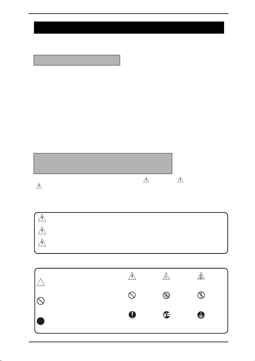
Symbols used for safety and important warning items are defined as follows:
:Precaution when servicing the
product.
:Prohibition when servicing the
product.
:Direction when servicing the
product.
General
precaution
General
prohibition
General
instruction
Electric hazard High temperature
Do not touch
with wet hand
UnplugGround/Earth
Do not
disassemble
S-1
Page 5
SAFETY AND IMPORTANT WARNING ITEMS
SAFETY WARNINGS
[1] MODIFICATIONS NOT AUTHORIZED BY KONICA MINOLTA
BUSINESS TECHNOLOGIES, INC.
KONICA MINOLTA brand products are renowned for their high reliability. This reliability is
achieved through high-quality design and a solid service network.
Product design is a highly complicated and delicate process where numerous mechanical,
physical, and electrical aspects have to be taken into consideration, with the aim of arriving
at proper tolerances and safety factors. For this reason, unauthorized modifications involve
a high risk of degradation in performance and safety. Such modifications are therefore
strictly prohibited. the points listed below are not exhaustive, but they illustrate the reasoning behind this policy.
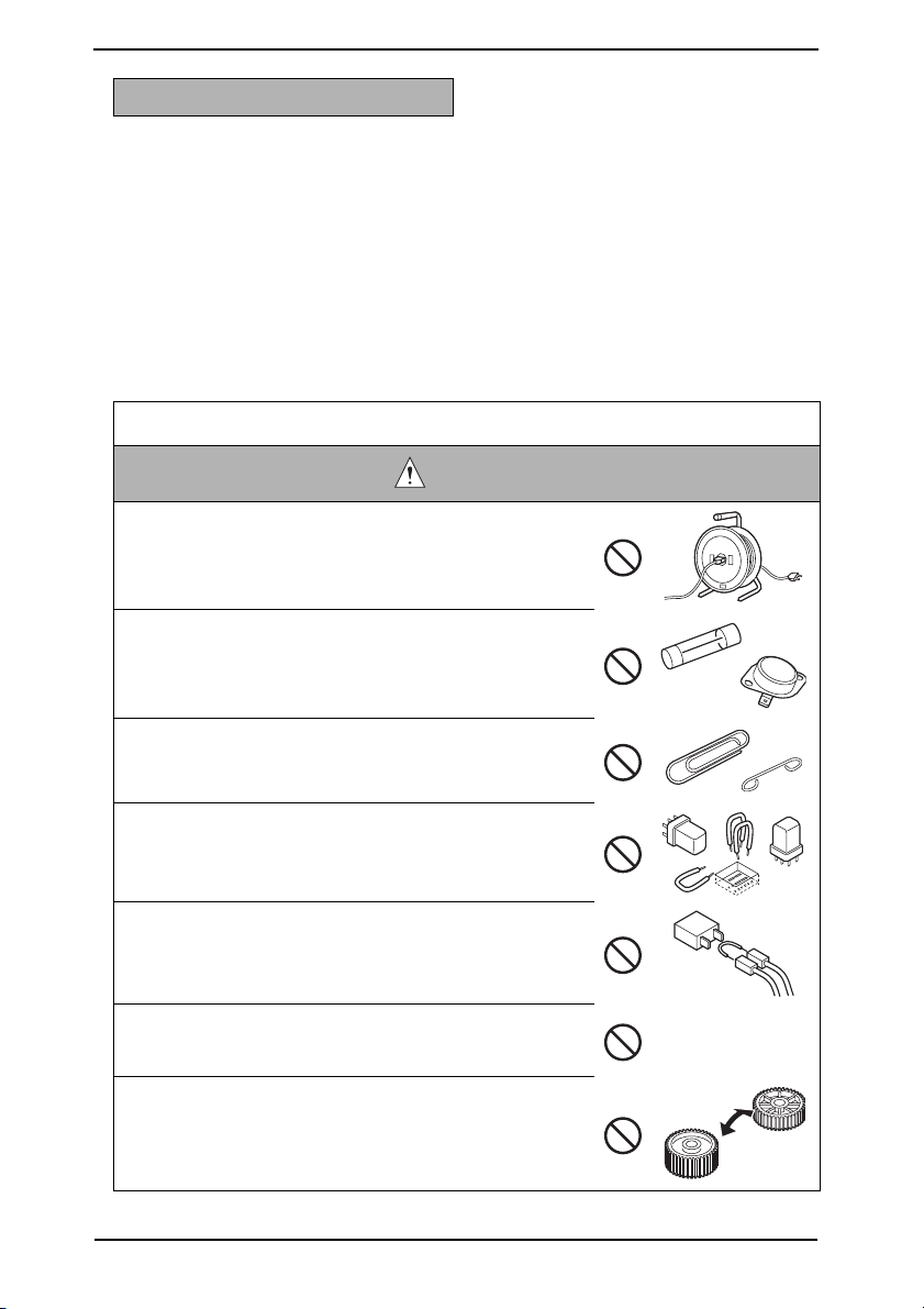
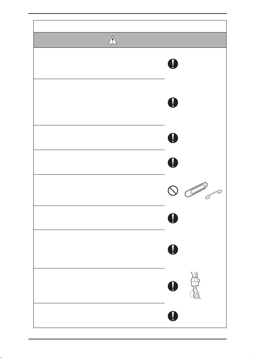
Prohibited Actions
DANGER
• Using any cables or power cord not specified by KMBT.
• Using any fuse or thermostat not specified by KMBT.
Safety will not be assured, leading to a risk of fire and
injury.
• Disabling fuse functions or bridging fuse terminals with
wire, metal clips, solder or similar object.
• Disabling relay functions (such as wedging paper between
relay contacts).
• Disabling safety functions (interlocks, safety circuits, etc.).
Safety will not be assured, leading to a risk of fire and
injury.
• Making any modification to the product unless instructed
by KMBT.
• Using parts not specified by KMBT.
S-2
Page 6
SAFETY AND IMPORTANT WARNING ITEMS
[2] POWER PLUG SELECTION
In some countries or areas, the power plug provided with the product may not fit wall outlet
used in the area. In that case, it is obligation of customer engineer (hereafter called the CE)
to attach appropriate power plug or power cord set in order to connect the product to the
supply.
Power Cord Set or Power Plug
WARNING
•Use power supply cord set which meets the following
criteria:
- provided with a plug having configuration intended for
the connection to wall outlet appropriate for the product’s rated voltage and current, and
- the plug has pin/terminal(s) for grounding, and
- provided with three-conductor cable having enough cur-
rent capacity, and
- the cord set meets regulatory requirements for the area.
Use of inadequate cord set leads to fire or electric shock.
• Attach power plug which meets the following criteria:
- having configuration intended for the connection to wall
outlet appropriate for the product’s rated voltage and
current, and
- the plug has pin/terminal(s) for grounding, and
- meets regulatory requirements for the area.
Use of inadequate cord set leads to the product connecting to inadequate power supply (voltage, current capacity,
grounding), and may result in fire or electric shock.
• Conductors in the power cable must be connected to terminals of the plug according to the following order:
•Black or Brown:L (line)
•White or Light Blue:N (neutral)
•Green/Yellow:PE (earth)
Wrong connection may cancel safeguards within the
product, and results in fire or electric shock.
kw
S-3
Page 7
SAFETY AND IMPORTANT WARNING ITEMS
[3] CHECKPOINTS WHEN PERFORMING ON-SITE SERVICE
KONICA MINOLTA brand products are extensively tested before shipping, to ensure that all
applicable safety standards are met, in order to protect the customer and customer engineer (hereafter called the CE) from the risk of injury. However, in daily use, any electrical
equipment may be subject to parts wear and eventual failure. In order to maintain safety
and reliability, the CE must perform regular safety checks.
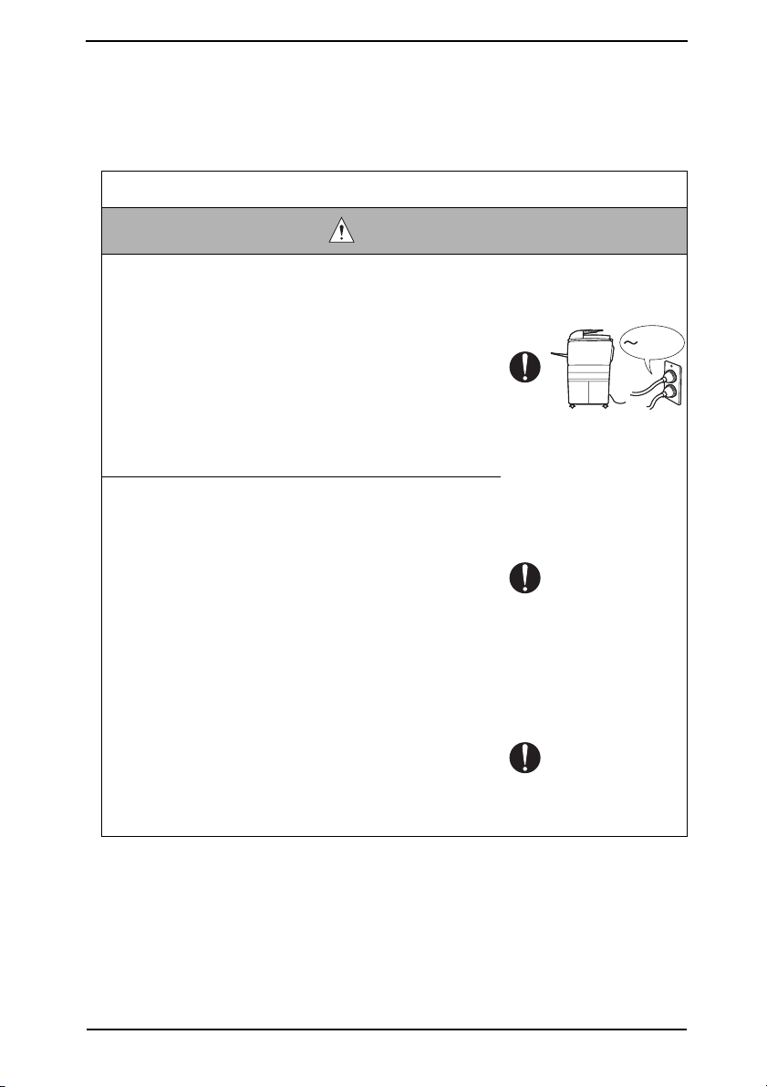
1. Power Supply
Connection to Power Supply
WARNING
• Check that mains voltage is as specified.
Connection to wrong voltage supply may result in fire or
electric shock.
• Connect power plug directly into wall outlet having same
configuration as the plug.
Use of an adapter leads to the product connecting to
inadequate power supply (voltage, current capacity,
grounding), and may result in fire or electric shock.
If proper wall outlet is not available, advice the customer
to contact qualified electrician for the installation.
•Plug the power cord into the dedicated wall outlet with a
capacity greater than the maximum power consumption.
If excessive current flows in the wall outlet, fire may
result.
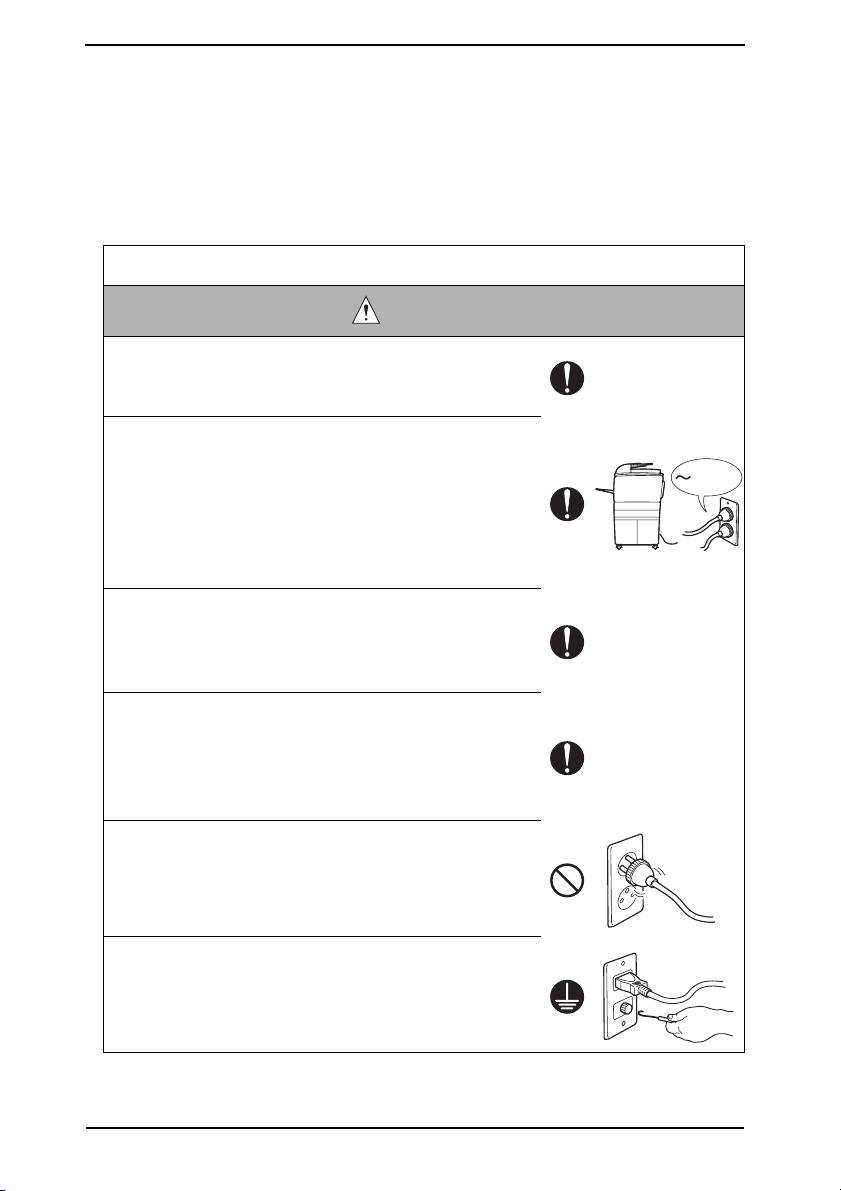
• If two or more power cords can be pl
outlet, the total load must not exceed the rating of the wall
outlet.
If excessive current flows in the wall outlet, fire may
result.
• Make sure the power cord is plugged in the wall outlet
securely.
Contact problems may lead to increased resistance,
overheating, and the risk of fire.
ugged into the wall
kw
• Check whether the product is grounded properly.
If current leakage occurs in an ungrounded product, you
may suffer electric shock while operating the product.
Connect power plug to grounded wall outlet.
S-4
Page 8
SAFETY AND IMPORTANT WARNING ITEMS
Power Plug and Cord
WARNING
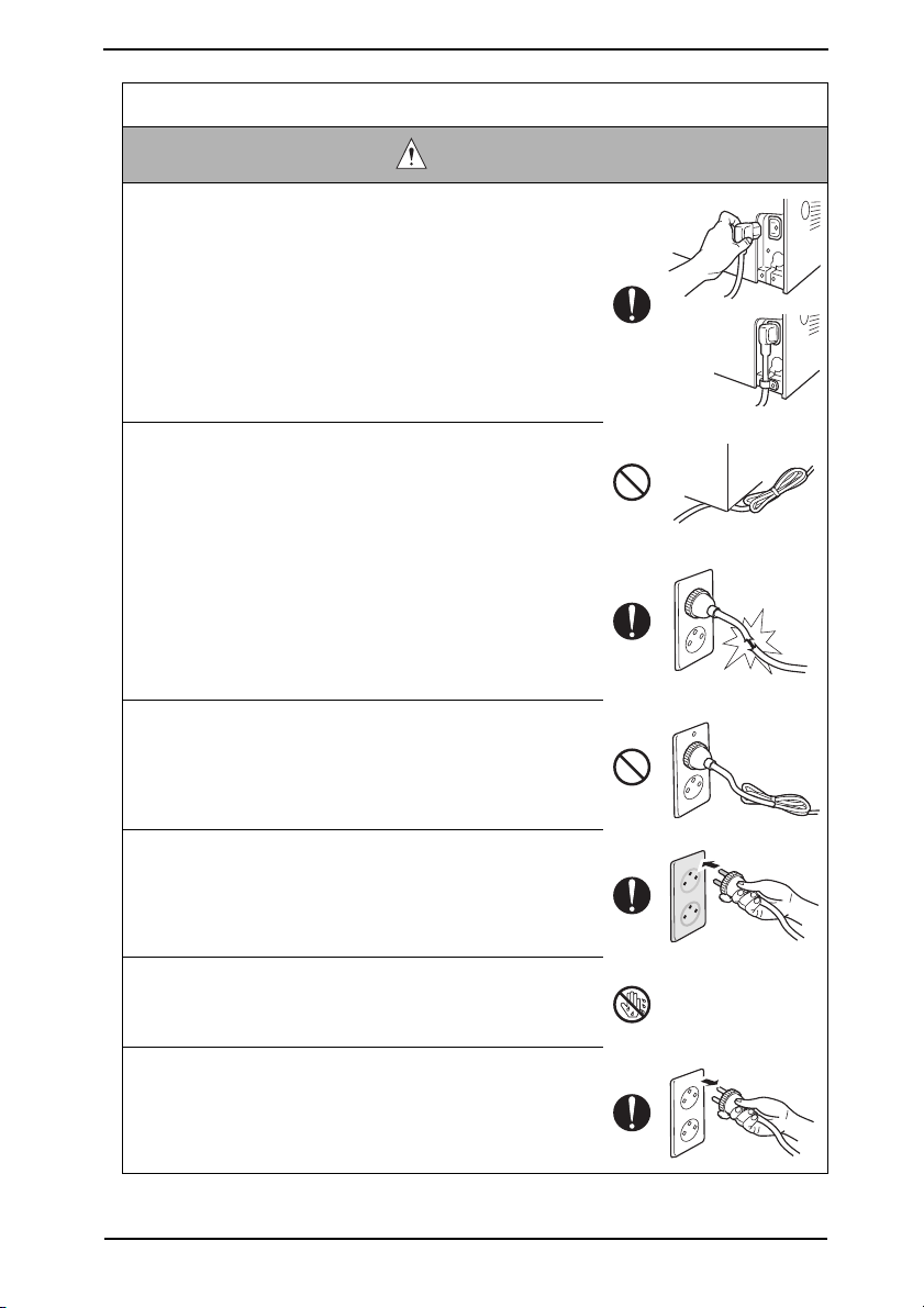
• When using the power cord set (inlet type) that came with
this product, make sure the connector is securely inserted
in the inlet of the product.
When securing measure is provided, secure the cord with
the fixture properly.
If the power cord (inlet type) is not connected to the product securely, a contact problem may lead to increased
resistance, overheating, and risk of fire.
• Check whether the power cord is not stepped on or
pinched by a table and so on.
Overheating may occur there, leading to a risk of fire.
• Check whether the power cord is damaged. Check
whether the sheath is damaged.
If the power plug, cord, or sheath is damaged, replace
with a new power cord (with plug and connector on each
end) specified by KMBT. Using the damaged power cord
may result in fire or electric shock.
• Do not bundle or tie the power cord.
Overheating may occur there, leading to a risk of fire.
• Check whether dust is collected around the po
and wall outlet.
Using the power plug and wall outlet without removing
dust may result in fire.
• Do not insert the power plug into the wall outlet with a wet
hand.
The risk of electric shock exists.
• When unplugging the power cord, grasp the plug, not the
cable.
The cable may be broken, leading to a risk of fire and
electric shock.
wer plug
S-5
Page 9
SAFETY AND IMPORTANT WARNING ITEMS
Wiring
WARNING
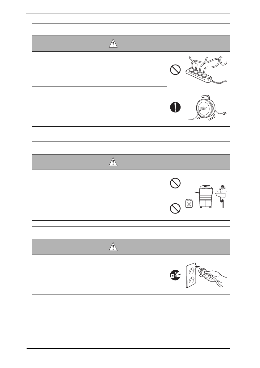
•Never use multi-plug adapters to plug multiple power cords
in the same outlet.
If used, the risk of fire exists.
• When an extension cord is required, use a specified one.
Current that can flow in the extension cord is limited, so
using a too long extension cord may result in fire.
Do not use an extension cable reel with the cable taken
up. Fire may result.
2. Installation Requirements
Prohibited Installation Places
WARNING
• Do not place the product near flammable materials or vola-
tile materials that may catch fire.
A risk of fire exists.
• Do not place the product in a place exposed to water such
as rain.
A risk of fire and electric shock exists.
When not Using the Product for a long time
WARNING
• When the product is not used over an extended period of
time (holidays, etc.), switch it off and unplug the power
cord.
Dust collected around the power plug and outlet may
cause fire.
S-6
Page 10
SAFETY AND IMPORTANT WARNING ITEMS
Ventilation
CAUTION
• The product generates ozone gas during operation, but it
will not be harmful to the human body.
If a bad smell of ozone is present in the following cases,
ventilate the room.
a. When the product is used in a poorly ventilated room
b. When taking a lot of copies
c. When using multiple products at the same time
Stability
CAUTION
•Be sure to lock the caster stoppers.
In the case of an earthquake and so on, the product may
slide, leading to a injury.
Inspection before Servicing
CAUTION
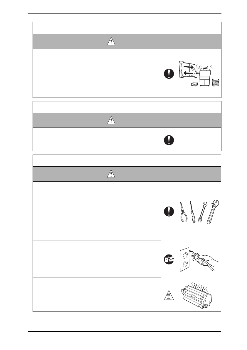
• Before conducting an inspection, read all relevant docu-
mentation (service manual, technical notices, etc.) and
proceed with the inspection following the prescribed procedure in safety clothes, using only the prescribed tools.
Do not make any adjustment not described in the docu-
mentation.
If the prescribed procedure or tool is not used, the product may break and a risk of injury or fire exists.
• Before conducting an inspection, be sure to disconnect
the power plugs from the product and options.
When the power plug is inserted in the wall outlet, some
units are still powered even if the POWER switch is
turned OFF. A risk of electric shock exists.
• The area around the fixing unit is hot.
Yo u may get burnt.
S-7
Page 11
SAFETY AND IMPORTANT WARNING ITEMS
Inspection before Servicing
CAUTION
• Do not leave the machine unattended during transporta-
tion, installation, and inspection of the machine. If it is to
be unavoidably left unattended, face protrusions toward
the wall or take other necessary risk reducing action.
The user may stumble over a protrusion of the machine
or be caught by a cable, falling to the floor or being
injured.
Work Performed with the Product Powered On
WARNING
• Take every care when making adjustments or performing
an operation check with the product powered.
If you make adjustments or perform an operation check
with the external cover detached, you may touch live or
high-voltage parts or you may be caught in moving gears
or the timing belt, leading to a risk of injury.
• Take every care when servicing with the external cover
detached.
High-voltage exists around the drum unit. A risk of electric shock exists.
• If it is absolutely necessary to service the machine with
the door open or external covers removed, always be
attentive to the motion of the internal parts.
A normally protected part may cause unexpected hazards.
Safety Checkpoints
WARNING
• Check the exterior and frame for edges, burrs, and other
damage.
The user or CE may be injured.
• Whenever mounting an option on the machine, be attentive to the motion of the fellow worker of the joint work.
The fellow worker may be injured with his or her finger or
hand pinched between the machine and the option.
S-8
Page 12
SAFETY AND IMPORTANT WARNING ITEMS
Safety Checkpoints
WARNING
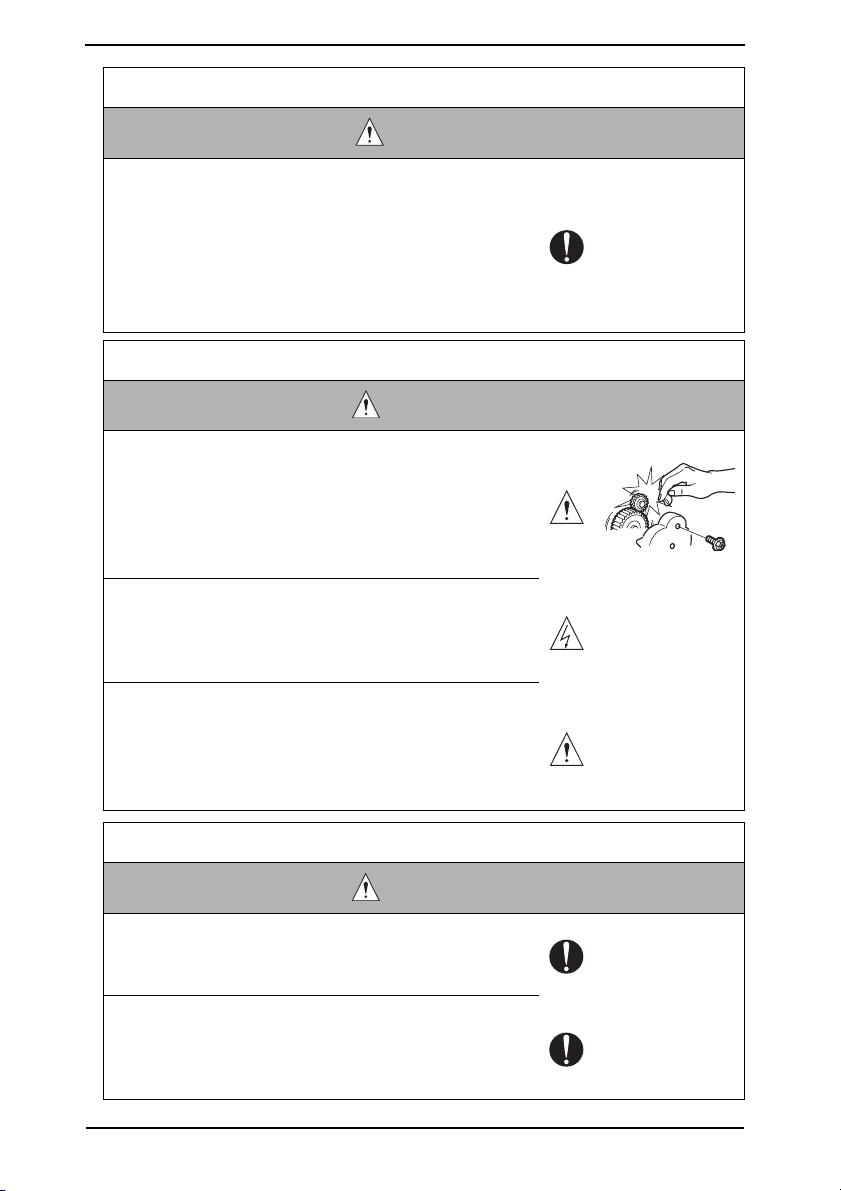
• When mounting an option on the machine, be careful
about the clearance between the machine and the option.
Yo u may be injured with your finger or hand pinched
between the machine and the option.
• When removing a part that secures a motor, gear, or other
moving part, disassembling a unit, or reinstalling any of
such parts and units, be careful about moving parts and
use care not to drop any part or unit. During the service
procedure, give sufficient support for any heavy unit.
Yo u may be injured by a falling part or unit.
• Check the external covers and frame for possible sharp
edges, burrs, and damage.
They can be a cause of injury during use or servicing.
• When accessing a hard-to-view or narrow spot, be caref
about sharp edges and burrs of the frame and parts.
They may injure your hands or fingers.
• Do not allow any metal parts such as clips, staples, and
screws to fall into the product.
They can short internal circuits and cause electric shock
or fire.
• Check wiring for squeezing and any other damage.
Current can leak, leading to a risk of electric shock or
fire.
•Carefully remove all toner remnants and dust from electri-
cal parts and electrode units such as a charging corona
unit.
Current can leak, leading to a risk of product trouble or
fire.
• Check high-voltage cables and sheaths for any damage.
Current can leak, leading to a risk of electric shock or
fire.
ul
• Check electrode units such as a charging corona unit for
deterioration and sign of leakage.
Current can leak, leading to a risk of trouble or fire.
S-9
Page 13
SAFETY AND IMPORTANT WARNING ITEMS
Safety Checkpoints
WARNING
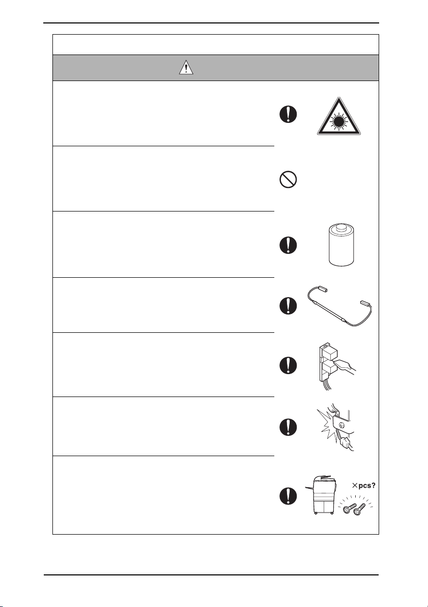
• Before disassembling or adjusting the write unit (P/H unit)
incorporating a laser, make sure that the power cord has
been disconnected.
The laser light can enter your eye, leading to a risk of
loss of eyesight.
• Do not remove the cover of the write unit. Do not supply
power with the write unit shifted from the specified mounting position.
The laser light can enter your eye, leading to a risk of
loss of eyesight.
• When replacing a lithium battery, replace it with a new lithium battery specified in the Parts Guide Manual. Dispose
of the used lithium battery using the method specified by
local authority.
Improper replacement can cause explosion.
• After replacing a part to which AC voltage is applied (e.g.,
optical lamp and fixing lamp), be sure to check the installation state.
A risk of fire exists.
• Check the interlock switch and actuator for loosening and
check whether the interlock functions properly.
If the interlock does not function, you may receiv
electric shock or be injured when you insert your hand in
the product (e.g., for clearing paper jam).
• Make sure the wiring cannot come into contact with sharp
edges, burrs, or other pointed parts.
Current can leak, leading to a risk of electric shock or
fire.
e an
• Make sure that all screws, components, wiring, connectors, etc. that were removed for safety check and maintenance have been reinstalled in the original location. (Pay
special attention to forgotten connectors, pinched cables,
forgotten screws, etc.)
A risk of product trouble, electric shock, and fire exists.
S-10
Page 14
SAFETY AND IMPORTANT WARNING ITEMS
Handling of Consumables
WARNING
• Toner and developer are not harmful substances, but care
must be taken not to breathe excessive amounts or let the
substances come into contact with eyes, etc. It may be
stimulative.
If the substances get in the eye, rinse with plenty of water
immediately. When symptoms are noticeable, consult a
physician.
•Never throw the used cartridge and toner into fire.
Yo u may be burned due to dust explosion.
Handling of Service Materials
CAUTION
• Unplug the power cord from the wall outlet.
Drum cleaner (isopropyl alcohol) and roller cleaner (acetone-based) are highly flammable and must be handled
with care. A risk of fire exists.
• Do not replace the cover or turn the product ON before
any solvent remnants on the cleaned parts have fully
evaporated.
A risk of fire exists.
• Use only a small amount of cleaner at a time and take
care not to spill any liquid. If this happens, immediately
wipe it off.
A risk of fire exists.
• When using any solvent, ventilate the room well.
Breathing large quantities of organic solvents can lead to
discomfort.
S-11
Page 15
SAFETY AND IMPORTANT WARNING ITEMS
[4] LASER SAFETY
• This is a digital machine certified as a Class 1 laser product. There is no possibility of
danger from a laser, provided the machine is serviced according to the instruction in this
manual.
4.1 Internal Laser Radiation
semiconductor laser
Maximum power of the laser diode 15 mW
Maximum average radiation power (*) 11.2 µW
Wavelength 770 - 800 nm
*at laser aperture of the Print Head Unit
• This product employs a Class 3B laser diode that emits an invisible laser beam. The
laser diode and the scanning polygon mirror are incorporated in the print head unit.
• The print head unit is NOT A FIELD SERVICEABLE ITEM. Therefore, the print head unit
should not be opened under any circumstances.
Laser Aperture of
the Print Head Unit
S-12
A121P0C504DA
Page 16

SAFETY AND IMPORTANT WARNING ITEMS
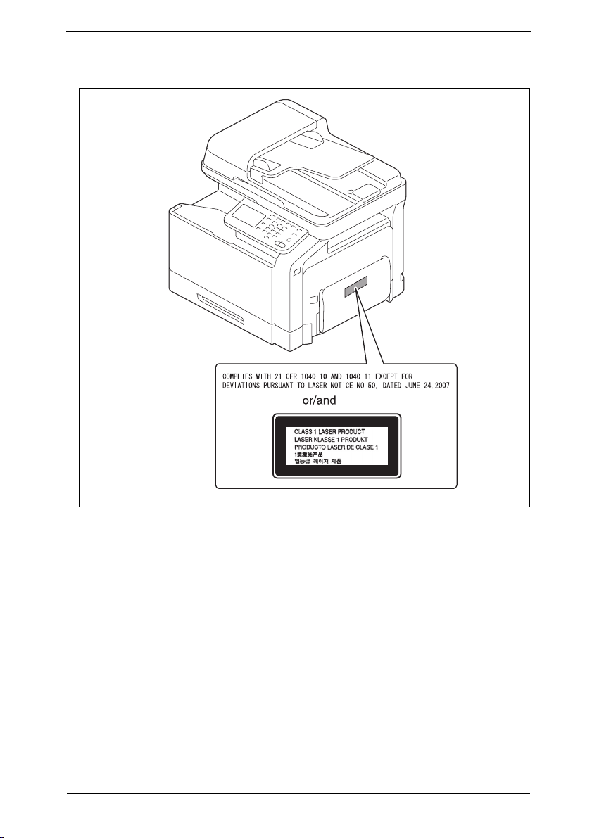
U.S.A., Canada
(CDRH Regulation)
• This machine is certified as a Class 1 Laser product under Radiation Performance Stan-
dard according to the Food, Drug and Cosmetic Act of 1990. Compliance is mandatory
for Laser products marketed in the United States and is reported to the Center for
Devices and Radiological Health (CDRH) of the U.S. Food and Drug Administration of
the U.S. Department of Health and Human Services (DHHS). This means that the device
does not produce hazardous laser radiation.
• The label shown on page S-15 indicates compliance with the CDRH regulations and
must be attached to laser products marketed in the United States.
.
CAUTION
• Use of controls, adjustments or performance of procedures other than those
specified in this manual may result in hazardous radiation exposure.
semiconductor laser
Maximum power of the laser diode 15 mW
Wavelength 770 - 800 nm
All Areas
CAUTION
• Use of controls, adjustments or performance of procedures other than those
specified in this manual may result in hazardous radiation exposure.
semiconductor laser
Maximum power of the laser diode 15 mW
Wavelength 770 - 800 nm
Denmark
ADVARSEL
• Usynlig laserstråling ved åbning, når sikkerhedsafbrydere er ude af funktion.
Undgå udsættelse for stråling. Klasse 1 laser produkt der opfylder IEC60825-1
sikkerheds kravene.
halvlederlaser
Laserdiodens højeste styrke 15 mW
bølgelængden 770 - 800 nm
S-13
Page 17

SAFETY AND IMPORTANT WARNING ITEMS
Finland, Sweden
LUOKAN 1 LASERLAITE
KLASS 1 LASER APPARAT
VAR OITU S!
• Laitteen käyttäminen muulla kuin tässä käyttöohjeessa mainitulla tavalla saattaa altistaa käyttäjän turvallisuusluokan 1 ylittävälle näkymättömälle lasersäteilylle.
puolijohdelaser
Laserdiodin suurin teho 15 mW
aallonpituus 770 - 800 nm
VARNING!
• Om apparaten används på annat sätt än i denna bruksanvisning specificerats,
kan användaren utsättas för osynlig laserstrålning, som överskrider gränsen för
laserklass 1.
halvledarlaser
Den maximala effekten för laserdioden 15 mW
våglängden 770 - 800 nm
VAR O!
• Avattaessa ja suojalukitus ohitettaessa olet alttiina näkymättomälle lasersäteilylle. Älä katso säteeseen.
VARNING!
• Osynlig laserstråining när denna del är öppnad och spärren är urkopplad.
Betrakta ej stråien.
Norway
ADVERSEL
• Dersom apparatet brukes på annen måte enn spesifisert i denne bruksanvisning, kan brukeren utsettes för unsynlig laserstrålning, som overskrider grensen
for laser klass 1.
halvleder laser
Maksimal effekt till laserdiode 15 mW
bølgelengde 770 - 800 nm
S-14
Page 18
SAFETY AND IMPORTANT WARNING ITEMS
4.2 Laser Safety Label
• A laser safety label is attached to the outside of the machine as shown below.
A121P0E505DA
S-15
Page 19
SAFETY AND IMPORTANT WARNING ITEMS
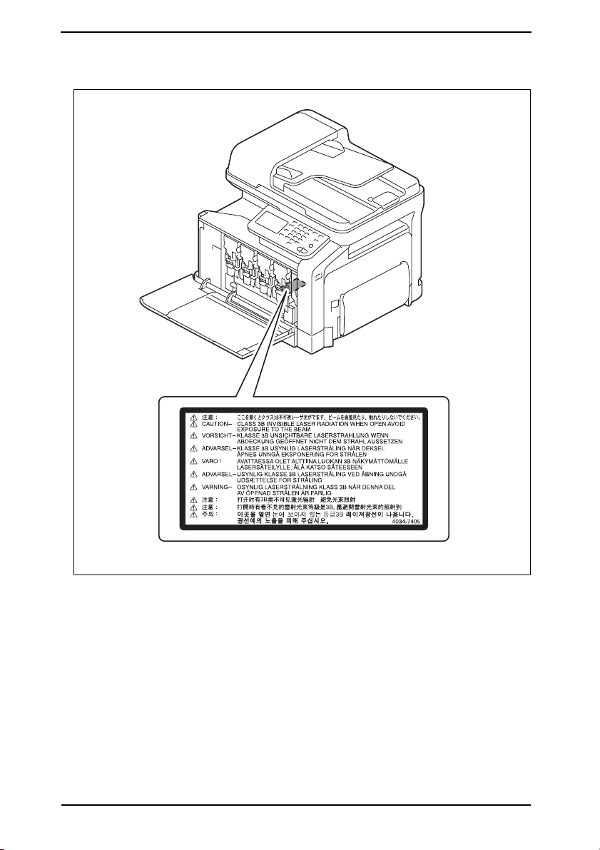
4.3 Laser Caution Label
• A laser caution label is attached to the inside of the machine as shown below.
A121P0C501DA
4.4 PRECAUTIONS FOR HANDLING THE LASER EQUIPMENT
• When laser protective goggles are to be used, select ones with a lens conforming to the
above specifications.
• When a disassembly job needs to be performed in the laser beam path, such as when
working around the printerhead and PC Drum, be sure first to turn the printer OFF.
• If the job requires that the printer be left ON, take off your watch and ring and wear laser
protective goggles.
• A highly reflective tool can be dangerous if it is brought into the laser beam path. Use
utmost care when handling tools on the user’s premises.
S-16
Page 20
SAFETY AND IMPORTANT WARNING ITEMS
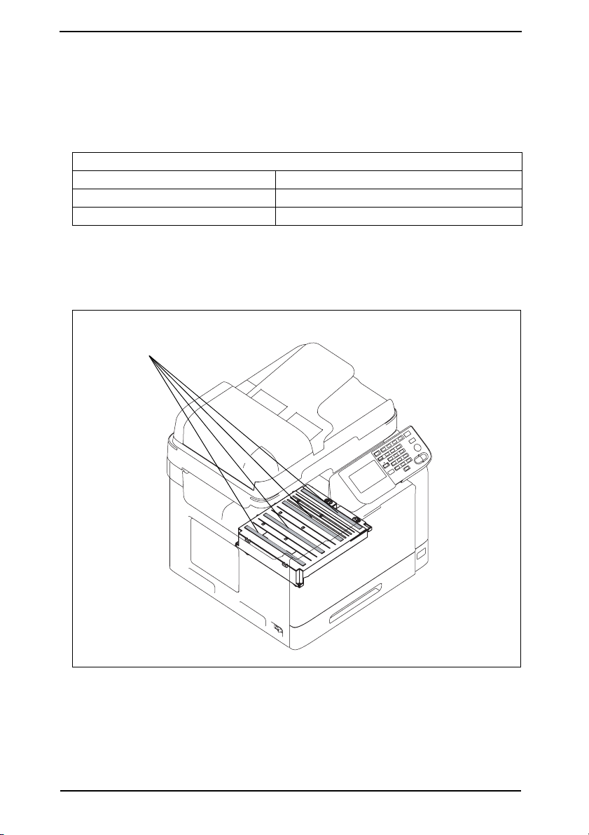
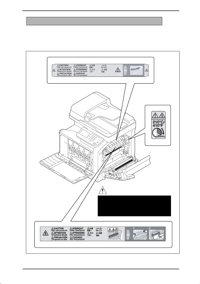
INDICATION OF WARNING ON THE MACHINE
Caution labels shown below are attached in some areas on/in the machine.
When accessing these areas for maintenance, repair, or adjustment, special care should
be taken to avoid burns and electric shock.
CAUTION
• The area around the Fuser Unit is
extremely hot.
Touching any part other than those
indicated may result in burns.
A121P0C503DA
S-17
Page 21
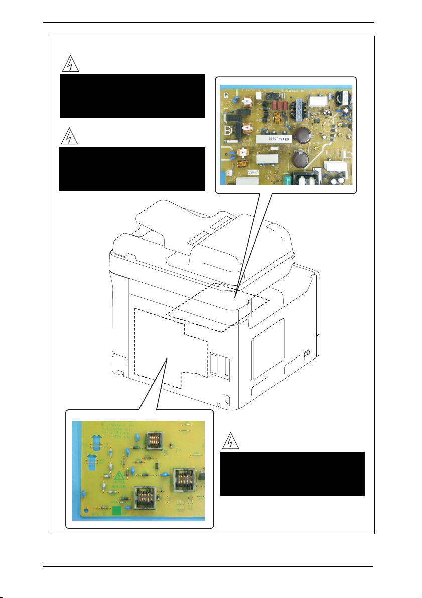
SAFETY AND IMPORTANT WARNING ITEMS
High voltage
• This area generates high voltage.
Be careful not to touch here when
the power is turned ON to avoid
getting an electric shock.
Electric hazard
• To avoid electrical shock, after
turning OFF the power switch, do
not touch the DC power supply for
9 minutes.
S-18
High voltage
• This area generates high voltage.
Be careful not to touch here when
the power is turned ON to avoid
getting an electric shock.
A121P0C506DA
Page 22
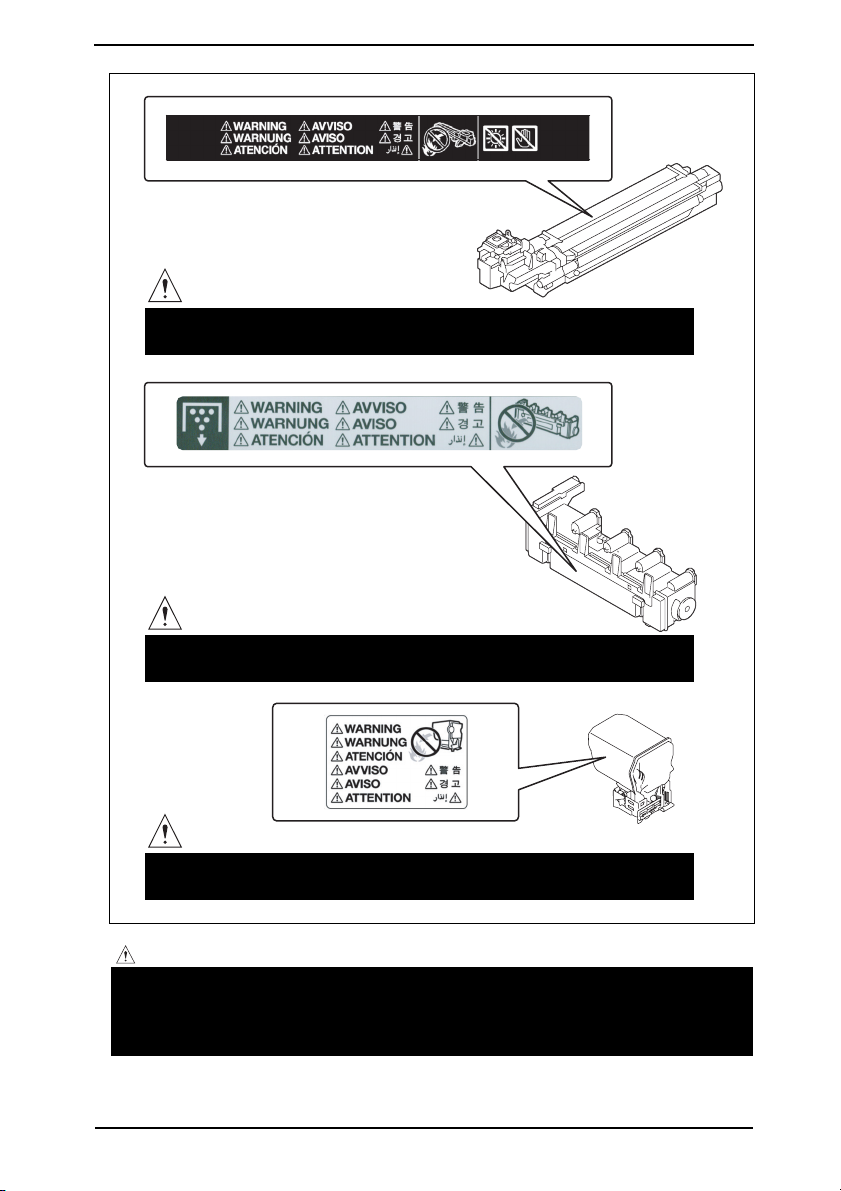
SAFETY AND IMPORTANT WARNING ITEMS
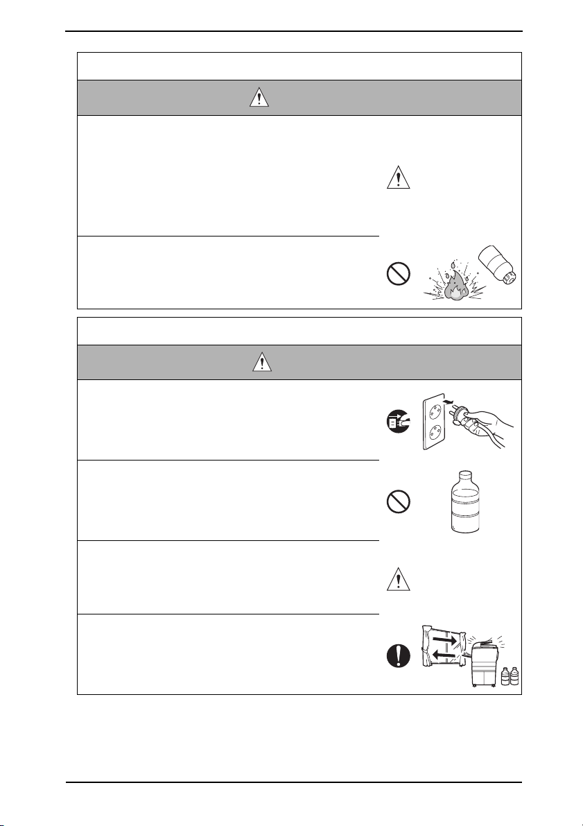
WARNING
• Do not burn used Imaging Unit.
Toner expelled from the fire is dangerous.
WARNING
• Do not burn used Waste Toner Bottle.
Toner expelled from the fire is dangerous.
WARNING
• Do not burn used Toner Cartridges.
Toner expelled from the fire is dangerous.
A0VDP0C504DA
CAUTION:
• You may be burned or injured if you touch any area that you are advised by any
caution label to keep yourself away from. Do not remove caution labels. And also,
when the caution label is peeled off or soiled and cannot be seen clearly, replace
it with a new caution label.
S-19
Page 23

MEASURES TO TAKE IN CASE OF AN ACCIDENT
MEASURES TO TAKE IN CASE OF
AN ACCIDENT
1. If an accident has occurred, the distributor who has been notified first must immediately
take emergency measures to provide relief to affected persons and to prevent further
damage.
2. If a report of a serious accident has been received from a customer, an on-site evalua-
tion must be carried out quickly and KMBT must be notified.
3. To determine the cause of the accident, conditions and materials must be recorded
through direct on-site checks, in accordance with instructions issued by KMBT.
4. For reports and measures concerning serious accidents, follow the regulations speci-
fied by every distributor.
S-20
Page 24

Composition of the service manual
This service manual consists of Theory of Operation section and Field Service section to
explain the main machine and its corresponding options.
Theory of Operation section gives, as information for the CE to get a full understanding of
the product, a rough outline of the object and role of each function, the relationship
between the electrical system and the mechanical system, and the timing of operation of
each part.
Field Service section gives, as information required by the CE at the site (or at the cus-
tomer’s premise), a rough outline of the service schedule and its details, maintenance
steps, the object and role of each adjustment, error codes and supplementary information.
The basic configuration of each section is as follows. However some options may not be
applied to the following configuration.
<Theory of Operation section>
OUTLINE: Explanation of system configuration,
product specifications, unit configuration, and paper path
COMPOSITION/OPERATION: Explanation of configuration of each unit,
operating system, and control system
<Field service section>
OUTLINE: Explanation of system configuration, and product
specifications
MAINTENANCE: Explanation of service schedule, maintenance steps, ser-
vice tools, removal/reinstallation methods of major parts,
and firmw
ADJUSTMENT/SETTING: Explanation of utility mode, service mode, and mechanical
adjustment etc.
TROUBLESHOOTING: Explanation of lists of jam codes and error codes, and
their countermeasures etc.
APPENDIX: Parts layout drawings, connector layout drawings, timing
chart, overall layout drawing are attached.
are version up method etc.
C-1
Page 25

Notation of the service manual
A. Product name
In this manual, each of the products is described as follows:
bizhub C35: Main body
(1)
(2) Microsoft Windows 2000: Windows 2000
Microsoft Windows XP: Windows XP
Microsoft Windows Vista: Windows Vista
Microsoft Windows 7: Windows 7
Microsoft Windows Server 2003: Windows Server 2003
Microsoft W
When the description is made in combination of the OS’s mentioned above:
B. Brand name
The company names and product names mentioned in this manual are the brand name or
the registered trademark of each company.
C. Feeding direction
• When the long side of the paper is parallel with the feeding direction, it is called short
edge feeding. The feeding direction which is perpendicular to the short edge feeding is
called the long edge feeding.
• Short edge feeding will be identified with [S (abbreviation for Short edge feeding)] on the
paper size. No specific notation is added for the long edge feeding.
When the size has only the short edge feeding with no long edge feeding, [S] will not be
added to the paper size.
<Sample notation>
indows Server 2008: Windows Server 2008
Windows 7/Vista/Server 2008/XP/Server
2003/2000
Windows 7/Vista/XP/2000
Windows Server 2008/Server 2003
Paper size Feeding direction Notation
A4
A3 Short edge feeding A3
Long edge feeding A4
Short edge feeding A4S
C-2
Page 26

SERVICE MANUAL
FIELD SERVICE
Main body
2011.02
Ver. 3.0
Page 27

Revision history
After publication of this service manual, the parts and mechanism may be subject to change for
improvement of their performance.
Therefore, the descriptions given in this service manual may not coincide with the actual machine.
When any change has been made to the descriptions in the service manual, a revised version will be
issued with a revision mark added as required.
Revision mark:
• To indicate clearly a section revised, is shown at the left margin of the revised section.
The number inside represents the number of times the revision has been made.
1
1
• To indicate clearly a page that contains the revision, is shown near the page number of the
1
corresponding page.
The number inside represents the number of times the revision has been made.
1
NOTE
Revision marks shown in a page are restricted only to the latest ones with the old ones deleted.
• When a page revised in Ver. 2.0 has been changed in Ver. 3.0:
The revision marks for Ver. 3.0 only are shown with those for Ver. 2.0 deleted.
• When a page revised in Ver. 2.0 has not been changed in Ver. 3.0:
The revision marks for Ver. 2.0 are left as they are.
2011/01 3.0
2010/12 2.0
2010/06 1.1 Error correction
2010/05 1.0 — Issue of the first edition
Date Service manual Ver. Revision mark Descriptions of revision
3
2
1
Description addition of the Step3 firmware
(A12130G1062205)/Error corrections
Description addition of the Step2 firmware
(A12130G0042905)/Error corrections
Page 28

Field Service Ver. 3.0 Feb. 2011
CONTENTS
bizhub C35 Main body
OUTLINE
1. SYSTEM CONFIGURATION................................................................................... 1
2. PRODUCT SPECIFICATIONS ................................................................................ 2
2.1 Type ...................................................................................................................... 2
2.2 Functions .............................................................................................................. 2
2.3 Media.................................................................................................................... 3
2.4 Maintenance ......................................................................................................... 3
2.5 Machine specifications.......................................................................................... 4
2.6 Operating environment ......................................................................................... 4
2.7 Print functions....................................................................................................... 4
2.8 Scan functions ...................................................................................................... 5
2.9 Fax functions ........................................................................................................ 6
MAINTENANCE
3. PERIODICAL MAINTENANCE ITEM...................................................................... 9
3.1 Periodical replacement parts list (CRU)................................................................ 9
3.2 Periodical replacement parts list (FRU) ................................................................ 9
3.2.1 Main body ..................................................................................................... 9
3.2.2 Option ........................................................................................................... 9
3.3 Concept of parts life.............................................................................................. 9
4. PERIODICAL MAINTENANCE PROCEDURE ..................................................... 10
4.1 Processing section.............................................................................................. 10
4.1.1 Replacing the toner cartridge (C, M, Y, K) .................................................. 10
4.1.2 Replacing the imaging unit (C, M, Y, K) ...................................................... 13
4.2 Transfer section .................................................................................................. 16
4.2.1 Replacing the waste toner bottle................................................................. 16
4.2.2 Replacing the transfer roller unit ................................................................. 17
4.2.3 Replacing the transfer belt unit ................................................................... 18
4.3 Fusing section..................................................................................................... 22
4.3.1 Replacing the fuser unit .............................................................................. 22
4.4 Feed section ....................................................................................................... 24
4.4.1 Replacing the tray1 feed roller .................................................................... 24
4.4.2 Replacing the tray2 feed roller .................................................................... 26
5. SERVICE TOOL .................................................................................................... 27
5.1 Service material list ............................................................................................ 27
bizhub C35
OUTLINEMAINTENANCEADJUSTMENT / SETTING
TROUBLESHOOTING
APPENDIX
i
Page 29

5.2 CE tool list .......................................................................................................... 27
6. FIRMWARE REWRITING..................................................................................... 28
6.1 Checking the current firmware version............................................................... 28
6.2 Firmware upgrading procedure by USB memory device.................................... 28
bizhub C35
6.2.1 Preparations for firmware upgrading........................................................... 28
6.3 Firmware upgrading procedure by updater ........................................................ 30
6.3.1 Updating method ........................................................................................ 30
6.3.2 Checking the version after the firmware update ......................................... 40
7. OTHER MAINTENANCE ITEM............................................................................. 41
7.1 Items not allowed to be disassembled and adjusted .......................................... 41
OUTLINEMAINTENANCEADJUSTMENT / SETTING
7.2 Disassembly/reassembly parts list ..................................................................... 42
7.3 Cleaning parts list............................................................................................... 43
7.4 Disassembly/reassembly procedure................................................................... 43
7.4.1 Front door ................................................................................................... 43
7.4.2 Rear cover .................................................................................................. 43
7.4.3 Left cover .................................................................................................... 44
7.4.4 Rear right cover .......................................................................................... 44
7.4.5 Operation panel .......................................................................................... 45
7.4.6 ADF............................................................................................................. 46
7.4.7 ADF feed roller unit..................................................................................... 48
7.4.8 ADF separation pad.................................................................................... 50
7.4.9 Scanner unit................................................................................................ 51
7.4.10 Tray1 ........................................................................................................... 53
7.4.11 Tray2 ........................................................................................................... 54
7.4.12 Hard disk (HDD) ......................................................................................... 54
7.4.13 FAX board (FAXB) ...................................................................................... 56
7.4.14 MFP board (MFPB)..................................................................................... 57
7.4.15 Printer control board (PRCB) ...................................................................... 61
7.4.16 DC power supply (DCPU)........................................................................... 63
7.4.17 High voltage unit (HV1)............................................................................... 65
TROUBLESHOOTING
7.4.18 PH Unit ....................................................................................................... 66
7.4.19 Backup battery............................................................................................ 68
7.4.20 Developing motor (M1) ............................................................................... 70
7.4.21 Main motor (M2) ......................................................................................... 70
7.4.22 Color PC drum motor (M4) ......................................................................... 70
APPENDIX
7.4.23 DC power su
7.4.24 Cooling fan motor (FM11) ........................................................................... 71
7.4.25 MFP board cooling fan motor (FM12)......................................................... 72
Field Service Ver. 3.0 Feb. 2011
pply fan motor (FM10)............................................................ 71
ii
Page 30

Field Service Ver. 3.0 Feb. 2011
7.4.26 Tray2 media feed clutch (CL1) / Tray1 media feed clutch (CL2).................. 73
7.4.27 Registration clutch (CL3) ............................................................................ 74
7.4.28 Toner supply clutch/Y (CL4) / Toner supply clutch/M (CL5)
Toner supply clutch/C (CL6) / Toner supply clutch/K (CL7)......................... 75
7.4.29 Loop detection clutch (CL8) ........................................................................ 78
7.4.30 Switchback roller feed clutch (CL11) / Switchback roller reverse clutch
(CL12) ......................................................................................................... 81
7.4.31 Duplex conveyance roller clutch (CL13)...................................................... 84
7.4.32 2nd transfer release solenoid (SD2) ........................................................... 85
7.4.33 Temperature/ humidity sensor (TEM/HUMS) .............................................. 87
7.4.34 IDC sensor (IDC) ........................................................................................ 88
7.4.35 Speaker (SP1)............................................................................................. 90
7.5 Cleaning procedure ............................................................................................ 91
7.5.1 Tray1 feed roller........................................................................................... 91
7.5.2 Tray2 feed roller........................................................................................... 91
7.5.3 ADF feed roller ............................................................................................ 92
7.5.4 Laser irradiation section .............................................................................. 92
ADJUSTMENT/SETTING
8. HOW TO USE THE ADJUSTMENT/SETTING
SECTION .............................................................................................................. 95
9. Utility ..................................................................................................................... 96
9.1 List of utility mode............................................................................................... 96
9.2 Starting/Exiting ................................................................................................. 103
9.2.1 Starting procedure .................................................................................... 103
9.2.2 Exiting procedure ......................................................................................103
9.3 Statistics Page.................................................................................................. 104
9.3.1 Sample of STATISTICS PAGE .................................................................. 104
9.4 Restore Defaults ............................................................................................... 109
10. SERVICE MODE................................................................................................. 119
10.1 List of service mode.......................................................................................... 119
10.2 Starting/Exiting ................................................................................................. 123
10.2.1 Starting procedure .................................................................................... 123
10.3 Serial Number................................................................................................... 124
10.4 Firmware Version.............................................................................................. 124
10.5 Printer Adjustment ............................................................................................ 125
10.5.1 Leading Edge Adjustment ......................................................................... 125
10.5.2 Side Edge Adjustment .............................................................................. 126
10.5.3 Left ADJ Duplex ........................................................................................ 127
bizhub C35
OUTLINEMAINTENANCEADJUSTMENT / SETTING
TROUBLESHOOTING
APPENDIX
iii
Page 31

10.5.4 2nd Image Transfer-Simplex Pass ............................................................ 128
10.5.5 2nd Image Transfer-Manual Duplex.......................................................... 128
10.5.6 Thick Paper Image Density....................................................................... 129
bizhub C35
10.5.7 Monochrome Density Adj.......................................................................... 129
10.5.8 Image ADJ Param..................................................................................... 129
10.5.9 Fuser Temp Control .................................................................................. 130
10.5.10 Fuser Control ............................................................................................ 130
10.5.11 AIDC Mode ............................................................................................... 130
10.5.12 Thick Mode ............................................................................................... 131
OUTLINEMAINTENANCEADJUSTMENT / SETTING
10.5.13 Fine Line ADJ ........................................................................................... 131
10.5.14 Grayscacle Page....................................................................................... 131
10.6 Main Scan Adjust ............................................................................................. 132
10.6.1 Main Scan Page........................................................................................ 132
10.6.2 Scan Adjust Value..................................................................................... 132
10.7 Service Fax Settings......................................................................................... 134
10.7.1 Restrict Fax TX ......................................................................................... 134
10.7.2 Restrict Fax RX......................................................................................... 134
10.7.3 Restrict PC-Fax TX ................................................................................... 134
10.7.4 TX Speed.................................................................................................. 134
10.7.5 RX Speed ................................................................................................. 135
10.7.6 ECM RX OFF............................................................................................ 135
10.7.7 Redial V34 Dis. ......................................................................................... 135
10.7.8 RX V34 OFF ............................................................................................. 135
10.7.9 V17 Mod. Permit. ...................................................................................... 135
10.7.10 Retry Start Pg ........................................................................................... 136
10.7.11 DT Detect.................................................................................................. 136
10.7.12 BT Detect.................................................................................................. 136
10.7.13 Cable Equalize.......................................................................................... 136
10.7.14 Echo Measure........................................................................................... 136
10.7.15 CFR to Phase C........................................................................................ 137
TROUBLESHOOTING
10.7.16 TX Level.................................................................................................... 137
10.7.17 Connect. Timeout ..................................................................................... 137
10.7.18 CED Level................................................................................................. 137
10.7.19 eRTN % .................................................................................................... 138
10.7.20 V34 Symbol Rate...................................................................................... 138
APPENDIX
10.7.21 Data Format.............................................................................................. 138
10.7.22 V34 Tran.Pt ............................................................................................... 138
10.7.23 Fax Target ................................................................................................. 138
Field Service Ver. 3.0 Feb. 2011
iv
Page 32

Field Service Ver. 3.0 Feb. 2011
10.7.24 Fax Factory Default ................................................................................... 139
10.7.25 Fax Image Initialized ................................................................................. 139
10.7.26 Fax Maint. ................................................................................................. 140
10.7.27 DTMF Test ................................................................................................ 140
10.7.28 Modem Test .............................................................................................. 140
10.7.29 Fax Diagnostics Code............................................................................... 141
10.7.30 Data Dmp. List ..........................................................................................141
10.7.31 Fax EventLog ............................................................................................ 141
10.7.32 Restrict Internet Fax TX ............................................................................ 141
10.7.33 Restrict Internet Fax RX............................................................................ 141
10.8 Scanner Adjustment ......................................................................................... 142
10.8.1 FB Leading Edge ...................................................................................... 142
10.8.2 FB Side Edge ............................................................................................ 143
10.8.3 ADF(F) Leading Edge ...............................................................................144
10.8.4 ADF(F) Side Edge..................................................................................... 145
10.8.5 ADF(B) Leading Edge ............................................................................... 146
10.8.6 ADF(B) Side Edge .................................................................................... 147
10.8.7 FB CD Multiplier ........................................................................................ 148
10.8.8 FB FD Multiplier ........................................................................................ 149
10.8.9 ADF(F) CD Multiplier................................................................................. 150
10.8.10 ADF(F) FD Multiplier ................................................................................. 151
10.8.11 ADF(B) CD Multiplier ................................................................................ 152
10.8.12 ADF(B) FD Multiplier................................................................................. 153
10.8.13 Tilt(F)......................................................................................................... 154
10.8.14 Tilt(B) ........................................................................................................ 154
10.9 Print Menu ........................................................................................................ 155
10.9.1 Mgmt. List ................................................................................................. 155
10.9.2 Event Log .................................................................................................. 157
10.9.3 Adjust Information ..................................................................................... 157
10.9.4 Element Page............................................................................................ 158
10.9.5 Halftone 64................................................................................................ 159
10.9.6 Halftone 128.............................................................................................. 159
10.9.7 Halftone 256.............................................................................................. 159
10.9.8 Gradation .................................................................................................. 160
10.9.9 Scanner Adjustment.................................................................................. 160
10.9.10 Scan Event Log......................................................................................... 160
10.10 Supplies ............................................................................................................ 160
10.10.1 Consumable Replace-Transfer Belt Unit ................................................... 160
bizhub C35
OUTLINEMAINTENANCEADJUSTMENT / SETTING
TROUBLESHOOTING
APPENDIX
v
Page 33

10.10.2 Consumable Replace-Transfer Roller Unit................................................ 161
10.10.3 Consumable Replace-Fusing Unit ............................................................ 161
10.11 BK Clear ........................................................................................................... 161
bizhub C35
10.12 Firmware Update.............................................................................................. 162
10.12.1 Details....................................................................................................... 162
10.12.2 Execute..................................................................................................... 162
10.13 CS Remote Care .............................................................................................. 163
10.13.1 Outlines..................................................................................................... 163
10.13.2 Setting up the CS Remote Care ............................................................... 163
OUTLINEMAINTENANCEADJUSTMENT / SETTING
10.13.3 Service Engr ID......................................................................................... 165
10.13.4 Subscribe.................................................................................................. 165
10.13.5 Maintenance Start. ................................................................................... 165
10.13.6 Maintenance End...................................................................................... 165
10.13.7 Manual Trans. ........................................................................................... 166
10.13.8 Basic Settings........................................................................................... 166
10.13.9 WebDAV Settings ..................................................................................... 167
10.13.10 CSRC Clock.............................................................................................. 168
10.13.11 CSRC Settings.......................................................................................... 168
10.13.12 RAM Clear ................................................................................................ 170
10.13.13 CS Remote Care Operation under Enhanced Security Mode .................. 170
10.14 Clear Admin Password ..................................................................................... 170
10.15 CE Password .................................................................................................... 171
10.16 Soft Switch ....................................................................................................... 172
10.17 Engine DipSW .................................................................................................. 172
10.18 Function............................................................................................................ 173
10.18.1 Print-Test Print A4/Test Print Letter........................................................... 173
10.18.2 Comp. Check ............................................................................................ 173
10.18.3 Sensor Check/Scanner Sensor Check ..................................................... 175
10.19 Toner Out Mode................................................................................................ 176
10.20 IU Yield Settings ............................................................................................... 176
TROUBLESHOOTING
10.21 Enable Warning ................................................................................................ 177
10.21.1 Toner Low ................................................................................................. 177
10.21.2 Imaging Unit Low ...................................................................................... 177
10.21.3 Waste Toner Box Near Full ....................................................................... 177
10.22 Installation Date................................................................................................ 177
10.23 Loadable Driver Information ............................................................................. 178
APPENDIX
10.24 Loadable Driver Download ............................................................................... 178
11. Billing Setting ...................................................................................................... 181
Field Service Ver. 3.0 Feb. 2011
vi
Page 34

Field Service Ver. 3.0 Feb. 2011
11.1 List of billing setting .......................................................................................... 181
11.2 Starting/Exiting ................................................................................................. 181
11.2.1 Starting procedure .................................................................................... 181
11.3 Count Setting.................................................................................................... 182
11.3.1 Count Mode .............................................................................................. 182
11.3.2 Large Paper size Mode ............................................................................. 182
11.4 Restriction Code Settings ................................................................................. 182
12. FAX PROTOCOLS .............................................................................................. 183
12.1 G3 ECM (G3 Error Correction Mode) ............................................................... 183
12.2 Line control ....................................................................................................... 184
12.2.1 Procedure of G3 mode communication..................................................... 184
12.3 Table of reference code .................................................................................... 185
12.4 How to analyze the T30 protocol monitor ......................................................... 186
TROUBLESHOOTING
13. JAM DISPLAY ..................................................................................................... 193
13.1 List of JAM display............................................................................................ 193
13.1.1 JAM display resetting procedure............................................................... 193
13.2 Sensor layout.................................................................................................... 194
13.3 Solution............................................................................................................. 195
13.3.1 Initial check items...................................................................................... 195
13.3.2 Misfeed at fusing/paper exit section.......................................................... 195
13.3.3 Misfeed at transfer section ........................................................................ 196
13.3.4 Misfeed at tray1 paper feed section .......................................................... 197
13.3.5 Misfeed at tray 2 paper feed section ......................................................... 198
13.3.6 Misfeed at tray 3/tray 4 paper feed section ............................................... 199
13.3.7 Misfeed at tray 3/tray 4 vertical conveyance section ................................. 200
13.3.8 Misfeed at duplex paper transport section ................................................ 201
13.3.9 Misfeed at duplex paper feed section........................................................ 202
13.3.10 Misfeed at ADF section............................................................................. 203
13.3.11 Controller JAM .......................................................................................... 204
14. PROCESS CAUTION INFROMATION ................................................................ 205
14.1 Display procedure............................................................................................. 205
14.2 List.................................................................................................................... 205
14.3 Solution............................................................................................................. 205
14.3.1 Temperature/ humidity sensor failure ........................................................ 205
14.3.2 IDC sensor failure ..................................................................................... 206
14.3.3 Color regist test pattern failure .................................................................. 206
14.3.4 Color regist adjust failure .......................................................................... 206
bizhub C35
OUTLINEMAINTENANCEADJUSTMENT / SETTING
TROUBLESHOOTING
APPENDIX
vii
Page 35

15. MALFUNCTION CODE....................................................................................... 207
15.1 Trouble code (Service Call) .............................................................................. 207
15.2 List.................................................................................................................... 207
15.3 Trouble resetting procedure.............................................................................. 210
bizhub C35
15.4 Solution ............................................................................................................ 211
15.4.1 0010: Color PC drum motor malfunction .................................................. 211
15.4.2 0017: Main motor malfunction .................................................................. 211
15.4.3 0018: Developing motor malfunction ........................................................ 212
15.4.4 0045: MFP board cooling fan motor malfunction ...................................... 212
15.4.5 004A: Cooling fan motor malfunction........................................................ 213
OUTLINEMAINTENANCEADJUSTMENT / SETTING
15.4.6 004E: DC power supply fan motor malfunction......................................... 213
15.4.7 0062: Tray 3 media feed motor malfunction.............................................. 214
15.4.8 0063: Tray 4 media feed motor malfunction.............................................. 214
15.4.9 0094: 2nd image transfer pressure/retraction failure ................................ 215
15.4.10 0096: 1st image transfer pressure/retraction failure ................................. 216
15.4.11 0300: Polygon motor malfunction ............................................................. 216
15.4.12 0310: Laser malfunction ........................................................................... 217
15.4.13 0500: Heating roller warm-up failure......................................................... 217
15.4.14 0502: Thermistor open-circuit failure ........................................................ 217
15.4.15 0503: Thermistor resistance failure .......................................................... 217
15.4.16 0510: Abnormally low heating roller temperature ..................................... 217
15.4.17 0520: Abnormally high heating roller temperature.................................... 217
15.4.18 0F52: Toner level sensor/Y malfunction.................................................... 218
15.4.19 0F53: Toner level sensor/M malfunction ................................................... 218
15.4.20 0F54: Toner level sensor/C malfunction.................................................... 218
15.4.21 0F55: Toner le
15.4.22 13DD: Backup data error .......................................................................... 218
15.4.23 13E2: Engine flash ROM write error ......................................................... 219
15.4.24 13E3: Engine flash ROM device fault ....................................................... 219
15.4.25 13F0: Engine control failure...................................................................... 219
TROUBLESHOOTING
15.4.26 6751: Gain adjustment error ..................................................................... 219
15.4.27 6790: Offset adjustment error ................................................................... 219
15.4.28 6792: White reference plate search error ................................................. 219
15.4.29 6793: Scanner communication error......................................................... 219
15.4.30 9401: Lamp illumination check error......................................................... 219
APPENDIX
15.4.31 6791: Register setting error ...................................................................... 220
15.4.32 B116: Communication error with the fax board......................................... 221
15.4.33 C023: Flash ROM error ............................................................................ 221
Field Service Ver. 3.0 Feb. 2011
vel sensor/K malfunction.................................................... 218
viii
Page 36

Field Service Ver. 3.0 Feb. 2011
15.4.34 C026: Controller ROM error (Access error) .............................................. 221
15.4.35 C027: Controller ROM error (Data error) .................................................. 221
15.4.36 C050: HDD access error........................................................................... 222
15.4.37 C051: HDD full error ................................................................................. 222
15.4.38 C060: Firmware update error.................................................................... 223
15.4.39 C072: Counter not installed ...................................................................... 223
15.4.40 C080: Memory error.................................................................................. 223
15.4.41 C900: Successful completion of counter backup ...................................... 224
15.4.42 C907: Abnormal end of counter backup ................................................... 224
15.4.43 FFFF: Interface communication error........................................................ 224
16. POWER SUPPLY TROUBLE .............................................................................. 225
16.1 Machine is not energized at all (DCPU operation check) ................................. 225
16.2 Control panel indicators do not light ................................................................. 225
16.3 Fusing heaters do not operate.......................................................................... 226
17. IMAGE QUALITY PROBLEM .............................................................................. 227
17.1 How to identify problematic part ....................................................................... 227
17.1.1 Initial check items...................................................................................... 227
17.2 Solution............................................................................................................. 228
17.2.1 Scanner system: white lines, white bands, colored lines and colored bands in
sub scan direction ..................................................................................... 228
17.2.2 Scanner system: white lines, white bands, colored lines and colored bands in
main scan direction ................................................................................... 229
17.2.3 Scanner system: color spots ..................................................................... 230
17.2.4 Scanner system: fog ................................................................................. 231
17.2.5 Scanner system: blurred image, blotchy image ........................................ 232
17.2.6 Scanner system: incorrect color image registration, sync shift (lines in main
scan direction)........................................................................................... 233
17.2.7 Scanner system: moire ............................................................................. 234
17.2.8 Scanner system: skewed image ............................................................... 235
17.2.9 Scanner system: distorted image.............................................................. 236
17.2.10 Scanner system: low image density, rough image .................................... 237
17.2.11 Scanner system: blank copy, black copy................................................... 238
17.2.12 Printer monocolor: white lines, white bands, colored lines and colored bands
in sub scan direction ................................................................................. 239
17.2.13 Printer monocolor: white lines, white bands, colored lines and colored bands
in main scan direction ............................................................................... 240
17.2.14 Printer monocolor: uneven density in sub scan direction.......................... 241
17.2.15 Printer monocolor:
uneven density in main scan direction........................ 242
17.2.16 Printer monocolor: low image density ....................................................... 243
bizhub C35
OUTLINEMAINTENANCEADJUSTMENT / SETTING
TROUBLESHOOTING
APPENDIX
ix
Page 37

bizhub C35
OUTLINEMAINTENANCEADJUSTMENT / SETTING
Field Service Ver. 3.0 Feb. 2011
17.2.17 Printer monocolor: gradation reproduction failure..................................... 244
17.2.18 Printer monocolor: foggy background....................................................... 245
17.2.19 Printer monocolor: void areas, white spots............................................... 246
17.2.20 Printer monocolor: colored spots .............................................................. 247
17.2.21 Printer monocolor: blurred image ............................................................. 248
17.2.22 Printer monocolor: blank copy, black copy................................................ 249
17.2.23 Printer monocolor: uneven image............................................................. 250
17.2.24 Printer 4-color: white lines, white bands, colored lines and colored bands in
sub scan direction..................................................................................... 251
17.2.25 Printer 4-color: white lines, white bands, colored lines and colored bands in
main scan direction................................................................................... 252
17.2.26 Printer 4-color: uneven density in sub scan direction ............................... 253
17.2.27 Printer 4-color: uneven density in main scan direction ............................. 254
17.2.28 Printer 4-color: low image density ............................................................ 255
17.2.29 Printer 4-color: poor color reproduction .................................................... 256
17.2.30 Printer 4-color: incorrect color image registration ..................................... 257
17.2.31 Printer 4-color: void areas, white spots..................................................... 258
17.2.32 Printer 4-color: colored spots.................................................................... 259
17.2.33 Printer 4-color: poor fusing performance, offset ....................................... 260
17.2.34 Printer 4-color: brush effect, blurred image .............................................. 261
17.2.35 Printer 4-color: back marking.................................................................... 262
17.2.36 Printer 4-color: uneven image................................................................... 263
18. IC protector ......................................................................................................... 264
18.1 Outline.............................................................................................................. 264
18.2 IC protector list ................................................................................................. 264
18.2.1 Main body ................................................................................................. 264
18.2.2 Lower feeder unit PF-P08 ......................................................................... 265
APPENDIX
19. PARTS LAYOUT DRAWING................................................................................ 267
TROUBLESHOOTING
APPENDIX
19.1 Main body......................................................................................................... 267
19.2 ADF .................................................................................................................. 271
19.3 Lower feeder unit (option)................................................................................. 272
20. CONNECTOR LAYOUT DRAWING.................................................................... 273
20.1 Printer control board (PRCB) ........................................................................... 273
20.2 MFP board (MFPB) .......................................................................................... 274
20.3 FAX board (FAXB) ............................................................................................ 274
20.4 PC control board (PCCB) ................................................................................. 275
20.5 DF control board (DFCB) ................................................................................. 275
x
Page 38

Field Service Ver. 3.0 Feb. 2011
21. CONNECTOR LAYOUT DRAWING .................................................................... 276
22. TIMING CHART .................................................................................................. 277
22.1 ADF .................................................................................................................. 278
bizhub C35
OUTLINEMAINTENANCEADJUSTMENT / SETTING
TROUBLESHOOTING
APPENDIX
xi
Page 39

bizhub C35
OUTLINEMAINTENANCEADJUSTMENT / SETTING
Field Service Ver. 3.0 Feb. 2011
Blank Page
TROUBLESHOOTING
APPENDIX
xii
Page 40

Field Service Ver. 3.0 Feb. 2011 1. SYSTEM CONFIGURATION
OUTLINE
1. SYSTEM CONFIGURATION
2
[1]
[2]
[2]
[1] bizhub C35 [2] PF-P08 (Lower feeder unit)
[3] DK-P01 (Desk) *1 [4] WT-P01 ( Working table)
2
[5] AU-201 (Authentication unit) [6] MK-727 (Panel sheet) *2
[6]
[5]
[3]
A0VDT2C544AB
*1: To be locally procured for North America/Europe.
*2: Panel sheet for traditional Chinese characters that is available as an option only in Tai-
wan.
bizhub C35
[4]
OUTLINE
1
2
Page 41

2. PRODUCT SPECIFICATIONS Field Service Ver. 3.0 Feb. 2011
2. PRODUCT SPECIFICATIONS
2.1 Type
Ty pe F ull-color printer/copier/scanner with stationary plate and ADF
2
bizhub C35
OUTLINE
Printing system Semiconductor laser and electrostatic image transfer to plain paper
Exposure system 4 laser diode and 1 polygon mirror
PC drum type OPC (organic photo conductor)
Photoconductor
cleaning
Scan resolution 600 x 1200 dpi, 600 x 600 dpi, 600 x 300 dpi
Luminous source CCFL Dual
Original scanning Flatbed CCD module scanning system
Print resolution 600 x 600 dpi
Paper feeding system Tray1: Small roller separation system with torque limiter
Developing system Single-element developing system
Charging system Charge roller system
Image transfer
system
Paper separating
system
Fusing system Belt fusing
Paper exit system Face down (Output tray capacity: 250 sheets (A4S/LetterS))
Blade cleaning system
Tray2: Small roller separation system with torque limiter
Intermediate transfer belt system
Curvature separation + charge-neutralizing system
2.2 Functions
Types of original Sheets, books, and three-dimensional objects
2
Max. original size A4 or Legal
Max. original weight 3 kg
Multiple copies 1 to 999
Image loss Copy
Warm-up time Power on to ready: average 45 seconds or less
Process speed 185 mm/sec. (plain paper)
First-page output time 12.9 second or less (A4S/LetterS, plain paper)
2
2
Leading edge: 4.0 mm, trailing edge: 4.0 mm, rear edge: 4.0 mm,
front edge: 4.0 mm
Print:
Leading edge: 4.2 mm, trailing edge: 4.2 mm, rear edge: 4.2 mm,
front edge: 4.2 mm
(Power on to ready, at ambient temperature of 23 °C/73.4 °F and rated source
voltage)
92.5 mm/sec.
(thick paper1/2, envelope, post card, label, letterhead, glossy 1/2)
Page 42

Field Service Ver. 3.0 Feb. 2011 2. PRODUCT SPECIFICATIONS
Copy speed Simplex
1
Monochrome/Full color:
30.0 page per minutes for A4 (plain paper)
31.6 page per minutes for Letter (plain paper)
15.0 page per minutes for A4 (thick paper1/2)
15.2 page per minutes for Letter (thick paper1/2)
Duplex (double-sided)
Monochrome/Full color:
30.0 sheet per minutes for A4 (plain paper)
31.6 sheet per minutes for Letter (plain paper)
15.0 page per minutes for A4 (thick paper1/2)
15.8 page per minutes for Letter (thick paper1/2)
Fixed zoom ratios Enlargement: x2.000, x1.631, x1.545, x1.414, x1.294, x1.224, x1.154
Reduction: x0.866, x0.816, x0.785, x0.707, x0.647, x0.607, x0.500
Variable zoom ratios Platen: x 0.250 to x4.000 (in x0.001 increments)
ADF: x 0.250 to x2.000 (in x0.001 increments)
2.3 Media
bizhub C35
OUTLINE
Ty pe
Media type Plain paper
(60 to 90 g/m
Thick 1 (91 to 150 g/m
Thick 2 (151 to 210 g/m
2
; 16 to 24 lb)
2
) 20 sheets 20 sheets
2
)
Paper source (maximum tray capacity)
Tray 1 Tray 2
100 sheets 250 sheets
Label
Letterhead
Glossy 1 (100 to 128 g/m
Glossy 2 (129 to 158 g/m
2
)
2
)
Postcar d
Envelope 10 sheets -
Media
dimensions
Width 92 to 216 mm*
(3.6 to 8.5 inch)
Length 148 to 356 mm*
(5.8 to 14.0 inch)
92 to 216 mm
(3.6 to 8.5 inch)
148 to 356 mm
(5.8 to 14.0 inch)
*: If the width set 210 mm to 216 mm, the max. length is to 279.4 mm.
2.4 Maintenance
Machine durability Main body 400,000 prints or 5 years, whichever comes first
2
Flatbed scanner unit 150,000 scans or 5 years, whichever comes first
ADF 200,000 scans or 5 years, whichever comes first
3
2
Page 43

2. PRODUCT SPECIFICATIONS Field Service Ver. 3.0 Feb. 2011
2.5 Machine specifications
Power requirements Voltage: AC 100 V, 120 V, 220 to 240 V
2
Current: 100 V 10.5 A or less
bizhub C35
Freq uency: 50 to 60 Hz
Max power consumption 1,200 W or less (100 V, 120 V)
OUTLINE
Dimensions 530 (W) x 508 (D) x 550 (H) mm
Weight 34.6 kg (76.28 lb) or less without consumables
Operating noise During standby : 39 dB (A) or less
110 V 9.0 A or less
120 V 9.0 A or less
127 V 9.0 A or less
220 to 240 V 4.8 A or less
1,100 W or less (110 V)
1,300 W or less (127 V, 220-240 V)
Power save mode: 34 W or less
20.87 (W) x 20.00 (D) x 21.65 (H) inch
39.0 kg (85.98 lb) or less with consumables
During printing : 55.0 dB (A) or less
During copying : 57.0 dB (A) or less
2.6 Operating environment
Temperature 10 °C to 30 °C / 50 °F to 86 °F (with a fluctuation of 10 °C / 18 °F or less per hour)
Humidity 15% to 85% (with a fluctuation of 10% or less per hour)
2.7 Print functions
Ty pe B uilt-in printer controller
2
RAM 1536 MB
HDD 120 GB (shared with the main body)/20 GB is available for user storage
Interface USB 2.0 (High Speed) compliant, 10Base-T/100Base-TX/1000Base-T Ethernet
Supported
protocols
Print speed 30 pages/min. (A4S, 1-sided print, plain paper)
Printer
language
Print resolution 600 x 600 dpi
Printer fonts PCL: 80 fonts, PostScript3: 137 fonts
4
2
TCP/IP, IPX/SPX, Ethertalk, SMB, Netware 4.x, 5.x , 6, IPP 1.1, POP3, LDAP,
SNMP v1, v2, v3, HTTP/HTTPS, IPv6, DPWS (WSD), IPP over SSL, IPSec (IPv6),
Bonjour, NTP, SSL/TLS, Dynamic DNS, LLTD
31.6 pages/min. (LetterS, 1-sided print, plain paper)
15 pages/min. (A4S, 1-sided print, thick paper)
15.8 pages/min. (LetterS, 1-sided print, thick paper)
PostScript3 (3016)
PCL 5 e/c, PCL 6 (XL3.0)
XPS (Version1.0)
PDF Direct Printing (Version 1.7)
JPEG/TIFF Direct Print
Page 44

Field Service Ver. 3.0 Feb. 2011 2. PRODUCT SPECIFICATIONS
Supported
operating
system
Printer driver PCL driver Windows 7/Vista/Server 2008/XP/Server 2003/2000
Windows Server 2008/Server 2003/Server 2008 x64 Edition/Server 2003 x64 Edition
Netware 4 / 5 / 6
Windows 7/Vista (ServicePack1)/Vista x64 Edition/XP (ServicePack2 or later)/XP x64
Edition/2000 (ServicePack4)/
Mac OS X (10.2.8/10.3.9/10.4/10.5/10.6)
Linux SUSE Linux Enterprise Desktop 10 (CUPS Ver. 1.1.23)
Red Hat Enterprise Linux 5 Desktop (CUPS Ver. 1.2.4)
Windows 7/Vista/Server 2008/XP/Server 2003 64bit
Windows 7/Vista/Server 2008/XP/Server 2003/2000 printer
driver for monochrome printing
Windows 7/Vista/Server 2008/XP/Server 2003 64bit printer
driver for monochrome printing
Windows 7/
Driver
Windows 7/Vista/Server 2008/XP/Server 2003 64bit
Universal Driver
PostScript driver Windows 7/Vista/Server 2008/XP/Server 2003/2000
Windows 7/Vista/Server 2008/XP/Server 2003 64bit
Windows 7/Vista/Server 2008/XP/Server 2003/2000 Universal
Driver
Windows 7/Vista/Server 2008/XP/Server 2003 64bit
Universal Driver
PostScript PPD driver Mac OS X (10.2.8/10.3.9/10.4/10.5/10.6)
Mac OS X Server (10.2/10.3/10.4/10.5/10.6)
Red Hat Enterprise Linux 5 Desktop
SUSE Linux Enterprise Desktop 10
XPS driver Windows 7/Vista/Serv
Windows 7/ Vista/Server 2008 64bit
PC FAX driver Windows 7/Vista/Server 2008/XP/Server 2003/2000
Windows 7/Vista/Server 2008/XP/Server 2003 64 bit
Vista/Server 2008/XP/Server 2003/2000 Universal
er 2008
bizhub C35
OUTLINE
2.8 Scan functions
2
Scannable range Same as the copier specification (Max. A4 or Legal)
Scan Speed
(ADF scan, resolution 300 dpi)
Functions Scan to E-mail, Scan to FTP, Scan to SMB, Scan to WebDAV,
Scanning resolution 150 x 150 dpi, 200 x 200 dpi, 300 x 300 dpi, 600 x 600 dpi
Supported operation system Windows 7/Vista/Server 2008/XP/Server 2003/2000
Drivers TWAIN Driver for Windows 7/Vista/Server 2008/XP/Server 2003/2000
Output file format TIFF, PDF, CompactPDF, JPEG, XPS
30 pages/min (A4)
31 pages/min (Letter)
Scan to HDD, Scan to USB memory, WSD scan
(Network Twain: 150/300/600/1,200/2,400/4,800 dpi)
Mac OS X (10.3.9/10.4/10.5/10.6)
TWAIN Driver for Mac OS X (10.3.9/10.4/10.5/10.6)
WIA Driver for Windows 7/Vista/Server 2008/XP
WIA Driver for Windows 7/Vista/Server 2008/XP 64bit
5
2
Page 45

2. PRODUCT SPECIFICATIONS Field Service Ver. 3.0 Feb. 2011
2.9 Fax functions
Applicable lines PSTN, PBX
bizhub C35
2
2
OUTLINE
2
2
Protocol Group 3 (compliant to ITU-T T.30)
Communication
resolution
(G3 fax)
Communication
resolution
(Internet fax)
Compatibility ECM/Super G3
Communication speed 2.4 to 33.6 kbps
Fax transmission
speed
Coding method G3 fax: MH, MR, MMR and JBIG
File type Monochrome (TIFF)
Modulation method V.27 ter, V.29, V.17 and V.34
Fax memory 256 MB
Max. scanning size ADF: 216 x 1000 mm
Max. recording size Legal
Scanning speed 30 sheets/minute (A4)
Functions Abbreviated dial Max. 2000 stations to be registered
• Konica Minolta non-standard protocol: No
•Group 4: No
TCP/IP, SMTP, POP3 (compliant to ITU-T T.37 and W-NET FAX)
Standard: 203 x 98 dpi
Fine: 203 x 196 dpi
Super fine: 406 x 391dpi
Transmission Standard: 200 x 100 dpi
Reception 204 x 98 dpi, 200 x 100 dpi
3 seconds/page (at A4, V.34, 33.6kbps, JBIG)
• Resolution: standard mode
• Konica Minolta standard original
Internet fax (Transmission): TIFF-S (MH)
Internet fax (Reception): TIFF-S (MH), TIFF-F (MR/MMR)
Original glass: Legal
The fax message is printed according to the setting of Print Separate Fax
Pages, if an original longer than the paper loaded in the machine is received.
15 sheets/minute (A4) with resolution in the super fine mode
Program dial Max. 400 numbers to be registered
Key pad dial 38 digits maximum (during off-hook dial mode)
Grou
p dial Max. 100 numbers to be registered. Up to 500
Manual redial Possible to select from five latest histories.
Fine: 200 x 200 dpi
204 x 196 dpi, 200 x 200 dpi
408 x 391 dpi, 400 x 400 dpi
204 x 391 dpi, 200 x 400 dpi, 300 x 300 dpi
60 digits maximum (during on-hook dial mode)
abbreviated dial numbers can be registered for
each group.
6
2
Page 46

Field Service Ver. 3.0 Feb. 2011 2. PRODUCT SPECIFICATIONS
Functions Automatic redial • Automatically redial when remote stations are
Pulse/tone switching Capable of switching from pulse to tone by using
PBX mode setting • Possible to turn ON or OFF the PBX connection
Off-hook Manual start is possible with the “Off-Hook” button
Call progress detection • DC loop (Depends on country spec)
Dialing system To be selected from among PB, 10 pps, and 20
Line monitoring sound ON (A-B):
Off-Hook alarm Notifies the user if the external telephone is off-
busy or return no responses or transmission
errors occur at the memory transmission.
Note that, this is not performed at a manual (offhook) transmission.
• Possible to receive during redial waiting.
• Another call is possible.
the [*] key on the [Key pad] or [Tone] key on LCD.
and to register the external access code.
• There is the automatic removal function of
external access code to registered abbreviated
remote station No. Nothing is automatic addition
function.
on the LCD screen.
• Dial tone (Depends on country spec)
•Busy tone (Depends on country spec)
pps
Monitoring sound is sounded for communication
phase between A and B.
ON (All):
Monitoring sound is sounded for commu
phase between A and E.
OFF:
Monitoring sound is not sounded.
hook at the end of fax communication.
nication
bizhub C35
OUTLINE
NOTE
• These specifications are subject to change without notice.
7
Page 47

2. PRODUCT SPECIFICATIONS Field Service Ver. 3.0 Feb. 2011
bizhub C35
OUTLINE
Blank Page
8
Page 48

Field Service Ver. 3.0 Feb. 2011 3. PERIODICAL MAINTENANCE ITEM
MAINTENANCE
3. PERIODICAL MAINTENANCE ITEM
3.1 Periodical replacement parts list (CRU)
•To ensure that the machine produces good prints and to extend its service life, it is rec-
ommended that the maintenance jobs described in this schedule be carried out as
instructed.
• The replacing time is to be determined by the total counter value.
• Maintenance conditions are based on A4S or letterS,1-side print.
2
Class Part to be replaced Number of prints Description
Imaging unit (C,M,Y,K)
Processing
section
Image transfer
section
Fusing section Fuser unit (FU-P02) 100,000 (2 pages/job) P. 2 2
Standard in-box toner cartridge (C,M,Y,K)
High-capacity toner cartridge
(C,M,Y,K)
Waste toner bottle (WB-P03)
Transfer roller (TF-P04) 100,000 (2 pages/job) P. 1 7
Transfer belt unit (TF-P05) 100,000 (2 pages/job) P. 1 8
30,000 (Continuous printing)
20,000 (2 pages/job)
6,000 (Continuous printing)
6,000 (Continuous printing)
36,000 (monochrome)
(Continuous printing)
9,000 (full color)
(Continuous printing)
3.2 Periodical replacement parts list (FRU)
3.2.1 Main body
Class Maintenance parts Quantity Parts No.
Tr ay 1
(Manual feed tray)
Tray2 Tray2 feed roller 1 4138 3032 ## 300,000 P. 2 6
Tray1 feed roller 1 4138 3032 ## 300,000 P. 2 4
Actual
durable cycle
Description
bizhub C35
Ref.
page
P. 1 3
P. 1 0
P. 1 6
MAINTENANCE
Ref.
page
3.2.2 Option
Class Maintenance parts Quantity Parts No.
Tr ay 3 /4
(Lower feeder unit)
Feed roller 1 4537 6214 ## 300,000 *1
Actual
durable cycle
Description
*1: For details, see the optional lower feeder unit (PF-P08) service manual.
3.3 Concept of parts life
• See the accompanying sheet “bizhub C35 Concept of parts life” for details.
Ref.
page
9
2
Page 49

4. PERIODICAL MAINTENANCE PROCEDURE Field Service Ver. 3.0 Feb. 2011
4. PERIODICAL MAINTENANCE PROCEDURE
4.1 Processing section
4.1.1 Replacing the toner cartridge (C, M, Y, K)
bizhub C35
A. Periodically replaced parts/cycle
3
• Standard-in box toner cartridge (C, M, Y, K): Every 6,000 images
• High-capacity toner cartridge (C, M, Y, K): Every 6,000 images
B. Removal procedure
1. Open the front cover [1].
MAINTENANCE
[1]
[1]
[1]
Y
M C K
A121F2C500DA
2. Slide the lock lever [1] to the left.
A121F2C501DA
3. Grab the handle of the toner cartridge [1] to be replaced, and then
pull out the toner cartridge [1].
A121F2C502DA
10
3
Page 50

Field Service Ver. 3.0 Feb. 2011 4. PERIODICAL MAINTENANCE PROCEDURE
C. Reinstallation procedure
1. Take the toner cartridge [2] out of its
plastic bag [1].
[2]
[1]
A0VDF2C521DA
3 ×
A0VDF2C522DA
[1]
bizhub C35
2. Gently shake the toner cartridge [1]
three times to agitate the toner.
MAINTENANCE
3. Peel off the protective film tape [1]
from the right side of the toner cartridge.
[1]
A0VDF2C523DA
11
Page 51

4. PERIODICAL MAINTENANCE PROCEDURE Field Service Ver. 3.0 Feb. 2011
4. Insert the toner cartridge [1] into the
[1]
bizhub C35
A121F2C503DA
machine.
5. Slide the lock lever [1] to the right to
lock the toner cartridge.
[1]
MAINTENANCE
A121F2C504DA
6. Remove the protective film [1].
12
[1]
[1]
A121F2C505DA
7. Close the front cover [1].
A121F2C506DA
Page 52

Field Service Ver. 3.0 Feb. 2011 4. PERIODICAL MAINTENANCE PROCEDURE
4.1.2 Replacing the imaging unit (C, M, Y, K) A. Periodically replaced parts/cycle
• Imaging unit (C, M, Y, K): Every 30,000 images (Continuous printing) or
3
20,000 images (2 pages/job)
B. Removal procedure
1. Remove the toner cartridge.
See P.10
2. Remove the waste toner bottle.
See P.16
3. Press down the “Push” marked place
[1].
4. Pull the imaging unit [2] out.
[1]
[2]
A121F2C507DA
C. Reinstallation procedure
[2]
1. Take the imaging unit [2] out of the
plastic bag [1].
bizhub C35
MAINTENANCE
[1]
A0VDF2C529DA
13
3
Page 53

4. PERIODICAL MAINTENANCE PROCEDURE Field Service Ver. 3.0 Feb. 2011
2. Hold the imaging unit with both
hands, and then shake it twice as
shown in the illustration.
bizhub C35
A0VDF2C530DA
MAINTENANCE
[2]
[1]
[1]
3. Remove the protective cover [1] from
the imaging unit.
4. Remove all packing tape [2] from the
imaging unit.
[2]
A0VDF2C531DA
5. Remove the paper [1] from the imag-
ing unit.
6. Remove the protective cover [2] from
the imaging unit.
A0VDF2C532DA
14
Page 54

Field Service Ver. 3.0 Feb. 2011 4. PERIODICAL MAINTENANCE PROCEDURE
7. Slide the imaging unit [1] in.
[1]
A121F2C508DA
8. Install the waste toner bottle.
See P.16
9. Install the toner cartridge.
See P.10
10. Close the front cover.
bizhub C35
MAINTENANCE
15
Page 55

4. PERIODICAL MAINTENANCE PROCEDURE Field Service Ver. 3.0 Feb. 2011
4.2 Transfer section
4.2.1 Replacing the waste toner bottle A. Periodically replaced parts/cycle
• Waste toner bottle: Every 36,000 images (monochrome) / 9,000 images (full color)
3
bizhub C35
B. Removal procedure
1. Open the front cover [1].
[1]
MAINTENANCE
[1]
[2]
[1]
4. To reinstall, reverse the order of removal.
A121F2C500DA
2. Raise the left and right handles [1] to
unlock the waste toner bottle.
A121F2C509DA
3. Grab the left and right handles [1],
remove the waste toner bottle [2].
A121F2C510DB
16
3
Page 56

Field Service Ver. 3.0 Feb. 2011 4. PERIODICAL MAINTENANCE PROCEDURE
4.2.2 Replacing the transfer roller unit A. Periodically replaced parts/cycle
•Transfer roller unit: Every 100,000 images (2 pages/job)
3
B. Removal procedure
1. Open the right door.
[1]
2. Push two levers [1] inside to unlock
the transfer roller.
3. Rotate the transfer roller unit [2] in
the direction of the arrow.
[2]
A121F2C511DA
bizhub C35
[1]
A121F2C512DA
4. Remove the transfer roller unit [1].
5. To reinstall, reverse the order of removal.
6. From the Menu, select [Service Mode] → [Supplies] → [Consumables Replace] →
[Transfer Roller Unit] and execute this function to reset the transfer roller counter value.
7. From the Menu, select [Admin Setting] → [Printer Setting] → [Quality Settings] → [Gra-
dation Adjust] → [AIDC Process] and execute this function.
MAINTENANCE
17
3
Page 57

4. PERIODICAL MAINTENANCE PROCEDURE Field Service Ver. 3.0 Feb. 2011
4.2.3 Replacing the transfer belt unit A. Periodically replaced parts/cycle
• Transfer belt unit: Every 100,000 images (2 pages/job)
3
B. Replacing procedure
bizhub C35
NOTE
Before replacing the transfer belt unit, be sure to perform the following items so that
the machine does not start to print jobs before the counter value of the transfer belt
unit is reset.
• Make sure that the machine does not have print jobs and fax reception data waiting to print.
• Be sure to disconnect the USB cable, (the network cable, and the fax cable) from
the machine.
1. Turn OFF the power switch.
2. Remove the toner cartridge (C,M,Y,K).
See P.10
3. Remove the waste toner bottle.
See P.16
4. Remove the imaging unit (C,M,Y,K).
See P.13
5. Open the right door [1].
MAINTENANCE
[1]
A121F2C513DA
6. Remove the top part [1] of the right
door.
[1]
A121F2C514DA
18
3
Page 58

Field Service Ver. 3.0 Feb. 2011 4. PERIODICAL MAINTENANCE PROCEDURE
7. Completely insert the protective
sheet [1] supplied with the transfer
belt unit in the direction of the arrow.
[1]
A121F2C555DA
NOTE
• If the protective sheet is not sup-
plied, use two sheets [1] of A4 or
Letter paper as shown in the illustration.
bizhub C35
[2]
[1]
A121F2C556DA
[1]
A121F2C517DA
[1]
A121F2C518DA
MAINTENANCE
8. Hold the both handles [1] and lower
the guide [2].
9. Hold the handles, and then carefully
pull out the transfer belt unit [1].
19
Page 59

4. PERIODICAL MAINTENANCE PROCEDURE Field Service Ver. 3.0 Feb. 2011
10. Pull the protective sheet [1] out.
bizhub C35
[1]
A121F2C557DA
11. Remove the protective cover [1] from
the new transfer belt unit.
[1]
NOTE
• Be careful not to touch the surface
of the belt.
MAINTENANCE
A0VDF2C536DA
20
[1]
[2]
[2]
[1]
12. Insert the transfer belt unit [2] along
the rail [1].
A121F2C519DA
13. Hold the both handles [1] and raise
the guide [2].
A121F2C559DA
Page 60

Field Service Ver. 3.0 Feb. 2011 4. PERIODICAL MAINTENANCE PROCEDURE
14. To reinstall, reverse the order of removal.
15. Turn ON the power switch.
NOTE
• Make sure that the USB cable, (the network cable, and the fax cable) are not connected to the machine.
16. From the Menu, select [Service Mode] → [Supplies] → [Consumables Replace] →
[Transfer Belt Unit] and execute this function to reset the transfer belt unit counter value.
17. From the Menu, select [Admin Setting] → [Printer Setting] → [Quality Settings] → [Gra-
dation Adjust] → [AIDC Process] and execute this function.
18. Connect the USB cable, (the network cable, and the fax cable) to the machine.
bizhub C35
MAINTENANCE
21
Page 61

4. PERIODICAL MAINTENANCE PROCEDURE Field Service Ver. 3.0 Feb. 2011
4.3 Fusing section
4.3.1 Replacing the fuser unit
bizhub C35
• The temperature gets high in the vicinity of the fuser unit. You may get
burned when you come into contact with the area. Before replacement
operations, make sure that more than 20 minutes have elapsed since the
main and sub power switches were turned off.
A. Periodically replacing parts/cycle
CAUTION
•Fuser unit: Every 100,000 images (2 pages/job)
3
B. Procedure
1. Turn OFF the power switch, unplug the power cord from the power outlet, and let the
machine to stand idle for about 20 min.
2. Open the right door [1].
MAINTENANCE
[1]
A121F2C513DA
[1]
3. Open the fuser unit cover [1].
A121F2C522DA
22
3
Page 62

Field Service Ver. 3.0 Feb. 2011 4. PERIODICAL MAINTENANCE PROCEDURE
4. Pull down two levers [1].
[1]
A121F2C523DA
5. Remove the fuser unit [1].
[1]
A121F2C524DA
6. Install the new fuser unit.
7. From the Menu, select [Service Mode] → [Supplies] → [Consumables Replace] →
[Fusing Unit] and execute this function to reset the fuser unit counter value.
bizhub C35
MAINTENANCE
23
Page 63

4. PERIODICAL MAINTENANCE PROCEDURE Field Service Ver. 3.0 Feb. 2011
4.4 Feed section
4.4.1 Replacing the tray1 feed roller
A. Periodically replaced parts/cycle
• Tray1 feed roller: Every 300,000 counts
bizhub C35
B. Procedure
1. Remove the tray1.
See P.53
2. Open the right door.
[1]
3. Detach the spring [1] from the hook
[2] in order to unlock the plate.
MAINTENANCE
[2]
[1]
[2]
A121F2C001DA
4. Remove six screws [1], and remove
the tray1 feed roller assy [2].
A0VDF2C001DA
24
Page 64

Field Service Ver. 3.0 Feb. 2011 4. PERIODICAL MAINTENANCE PROCEDURE
[1]
[2]
[1]
[3]
[2]
A0VDF2C003DA
[2]
A0VDF2C004DA
[3]
5. Remove the E-ring [1] and the bear-
ing [2], and move the tray 1 feed
roller assy [3] in the direction of the
arrow.
bizhub C35
NOTE
• When reinstalling the tray 1 feed
roller assy, the stopper [1] must be
located under the shaft [2] as
shown in the illustration.
MAINTENANCE
6. Remove the E-ring [1] and mecha-
nism clutch [2], and remove the tray1
feed roller [3].
[1]
[1]
A0VDF2C005DA
7. To reinstall, reverse the order of
removal.
NOTE
• When reinstalling the feed roller [1],
make sure that it is mounted in the
direction shown in the illustration
on the left.
A0VDF2C547DA
25
Page 65

4. PERIODICAL MAINTENANCE PROCEDURE Field Service Ver. 3.0 Feb. 2011
4.4.2 Replacing the tray2 feed roller A. Periodically replaced parts/cycle
• Tray2 feed roller: Every 300,000 counts
B. Procedure
bizhub C35
1. Remove the tray2.
See P.54
[3] [1]
2. Lock the media lift metal plate [1].
3. Remove two E-rings [2] and the
bearing [3].
MAINTENANCE
[2]
[2]
[1]
A121F2C002DA
A121F2C003DA
[1]
A0VDF2C546DA
4. Remove the C-ring [1], and remove
the tray2 feed roller [2].
5. To reinstall, reverse the order of
removal.
NOTE
• When reinstalling the feed roller [1],
make sure that it is mounted in the
direction shown in the illustration
on the left.
26
Page 66

Field Service Ver. 3.0 Feb. 2011 5. SERVICE TOOL
5. SERVICE TOOL
5.1 Service material list
Tool name Shape Material No. Remarks
Cleaning pad 000V-18-1 10pcs/1pack
A02EF2C526DA
Isopropyl alcohol 000V-19-0
A00KF2C506DA
5.2 CE tool list
Tool name Shape Quantity Parts No.
Laser lens cleaning tool 1 A0VD 1089 ##
A0VDF2C553DA
bizhub C35
MAINTENANCE
27
Page 67

6. FIRMWARE REWRITING Field Service Ver. 3.0 Feb. 2011
6. FIRMWARE REWRITING
6.1 Checking the current firmware version
1. Call the Service Mode to the screen.
2. To uch [Firmware Version].
bizhub C35
3. Select the firmware to be updated and check the current version.
6.2 Firmware upgrading procedure by USB memory device
6.2.1 Preparations for firmware upgrading
MAINTENANCE
A. System requirements
•PC equipped with a USB port
• USB memory device
B. Saving the firmware data into the USB memory device
1. Save the firmware data in appropriate space in the PC.
2. Connect the USB memory device to the PC.
3. Create a “firmware” folder immediately under the drive of the USB memory device.
4. Copy the firmware data (***.exe) in the firmware folder created in step 3.
NOTE
• Be sure to save the firmware data in “drive:/firmware/***.exe.”
• The printer can display up to 20 files of firmware data during upgrading.
A121F2C533DA
28
Page 68

Field Service Ver. 3.0 Feb. 2011 6. FIRMWARE REWRITING
C. How to write firmware data
1. Turn the power switch ON.
2. Connect the USB memory device to the printer.
3. Call the Service Mode to the screen.
4. To uch [Firmware Update].
A121F2C534DA
5. A list of firmware data in the USB memory device will be displayed.
2
bizhub C35
MAINTENANCE
A121F2C535DB
NOTE
• Before upgrading firmware, use [Details] to check that the firmware data is correct.
2
A121F2C536DB
6. To uch [Close].
29
2
Page 69

6. FIRMWARE REWRITING Field Service Ver. 3.0 Feb. 2011
7. Select the specific firmware data to be upgraded and press [Execute].
8. To uch [OK].
2
bizhub C35
9. The firmware upgrading procedure starts.
NOTE
• NEVER disconnect the USB memory device from the printer during the firmware
upgrading procedure.
10. The printer is automatically restarted as soon as the firmware is upgraded correctly.
6.3 Firmware upgrading procedure by updater
MAINTENANCE
6.3.1 Updating method
•To update the firmware, perform “Firmware Updater.”
A121F2C537DB
A. System requirements
2
Computer Windows•PC with a Pentium 2, 400 MHz or faster processor
OS Windows • Microsoft Windows XP Home Edition/Professional, Windows
Available
hard disk space
Interface Windows • 10Base-T/100Base-TX/1000Base-T Ethernet
30
2
(A Pentium 3, 500 MHz or faster processor is recommended.)
2000, Windows Vista Home Basic/Home Premium/Business/
Enterprise/Ultimate
Windows
Memory • 128 MB or more
• Approximately 20 to 26 MB
• USB 2.0 (High Speed) compliant
Page 70

Field Service Ver. 3.0 Feb. 2011 6. FIRMWARE REWRITING
B. Connection for Windows
(1) Starting the firmware updater
NOTE
• Before starting the firmware updater, turn on the printer, and make sure that it is
correctly connected.
1. Download the firmware updater.
2. Double-click “xxxxxxxxxxxx.exe.”
3. The printer name and firmware version are displayed. Click the [Next].
XXXXXXX
A121S1E031DA
4. The license agreement is displayed. Select “I agree”, and then click the [Next].
bizhub C35
MAINTENANCE
A121S1E010DA
31
Page 71

6. FIRMWARE REWRITING Field Service Ver. 3.0 Feb. 2011
5. The list of printer drivers is displayed. Select the appropriate connection for the environ-
ment where the printer is being used.
bizhub C35
XXXXXXX
XXXXXXX
• For a network connection: Select “Network port.”
See P.33
• For a local connection: Select “Local port.”
MAINTENANCE
See P.36
• When specifying the IP address of the printer: Select “Printer IP address.”
See P.37
NOTE
• If you select “Network port” or “Local port”, make sure that the printer driver has
been installed.
• If you select “Printer IP address”, the firmware can be updated even if a printer
driver is not already installed.
A121F2E538DA
32
Page 72

Field Service Ver. 3.0 Feb. 2011 6. FIRMWARE REWRITING
(2) For a network connection
1. When “Network port” is selected, a list of printer drivers for the network port appears.
2. Select the printer driver, and then click the [Next].
A121S1E011DA
3. A message appears, requesting confirmation to update the firmware. Click the [Start] to
begin transferring the firmware.
NOTE
• Do not turn off the printer while its firmware is being updated.
bizhub C35
MAINTENANCE
A121S1E012DA
33
Page 73

6. FIRMWARE REWRITING Field Service Ver. 3.0 Feb. 2011
4. The result of the firmware transfer is displayed. Click the [Exit].
bizhub C35
5. If the firmware was successfully updated, the printer will automatically restart.
MAINTENANCE
A121S1E013DB
34
Page 74

Field Service Ver. 3.0 Feb. 2011 6. FIRMWARE REWRITING
<If spooling of the data fails>
NOTE
• If spooling fails, data may remain in the printer spooler. Delete this data, and then
try again.
1. If spooling of the data fails, the following message appears.
2. Click [OK].
A121S1E014DA
3. Check that the printer is ready and that it is correctly connected, and then click the
[Update again].
bizhub C35
MAINTENANCE
A121S1E015DA
35
Page 75

6. FIRMWARE REWRITING Field Service Ver. 3.0 Feb. 2011
(3) For a local connection
1. When “Local port” is selected, a list of printer drivers for the local port appears.
2. Select the printer driver, and then click the [Next].
bizhub C35
3. A message appears, requesting confirmation to update the firmware. Click the [Start] to
begin transferring the firmware.
MAINTENANCE
NOTE
• Do not turn off the printer while its firmware is being updated.
A121S1E016DA
36
A121S1E017DA
Page 76

Field Service Ver. 3.0 Feb. 2011 6. FIRMWARE REWRITING
4. The result of the firmware transfer is displayed. Click the [Exit].
A121S1E018DA
5. If the firmware was successfully updated, the printer will automatically restart.
<If spooling of the data fails>
For details, see “For a network connection.”
See P.35
(4) When specifying the IP address of the printer
1. When “Printer IP address” is selected, the “Printer IP address” box becomes available.
2. Type in the IP address, and then click the [Next].
bizhub C35
MAINTENANCE
A121S1E019DA
37
Page 77

6. FIRMWARE REWRITING Field Service Ver. 3.0 Feb. 2011
3. A message appears, requesting confirmation to update the firmware. Click the [Start] to
begin transferring the firmware.
NOTE
• Do not turn off the printer while its firmware is being updated.
bizhub C35
4. The result of the firmware transfer is displayed. Click the [Exit].
MAINTENANCE
A121S1E020DA
5. If the firmware was successfully updated, the printer will automatically restart.
38
A121S1E021DA
Page 78

Field Service Ver. 3.0 Feb. 2011 6. FIRMWARE REWRITING
<If transferring of the data fails>
1. If transferring of the data fails, the following message appears.
2. Click [OK].
A121S1E022DA
3. Check that the printer is ready and that it is correctly connected, and then click the
[Update again].
bizhub C35
MAINTENANCE
A121S1E023DA
39
Page 79

6. FIRMWARE REWRITING Field Service Ver. 3.0 Feb. 2011
6.3.2 Checking the version after the firmware update
1. Call the Service Mode to the screen.
2. To uch [Firmware Version].
3. Select the firmware to be updated and check the current version.
bizhub C35
MAINTENANCE
A121F2C533DA
40
2
Page 80

Field Service Ver. 3.0 Feb. 2011 7. OTHER MAINTENANCE ITEM
7. OTHER MAINTENANCE ITEM
7.1 Items not allowed to be disassembled and adjusted
A. Paint-locked screws
NOTE
• To prevent loose screws, a screw lock in blue or green series color is applied to
the screws.
• The screw lock is applied to the screws that may get loose due to the vibrations
and loads created by the use of machine or due to the vibrations created during
transportation.
• If the screw lock coated screws are loosened or removed, be sure to apply a screw
lock after the screws are tightened.
B. Red-painted screws
NOTE
• The screws which are difficult to be adjusted in the field are painted in red in order
to prevent them from being removed by mistake.
• Do not remove or loosen any of the red-painted screws in the field. It should also
be noted that, when two or more screws are used for a single part, only one representative screw may be marked with the red paint.
bizhub C35
C. Variable resistors on board
NOTE
• Do not turn the variable resistors on boards for which no adjusting instructions
are given in Adjustment/Setting.
D. Removal of PWBs
CAUTION
• To avoid electrical shock, after turning OFF the power switch, do not touch the DC
power supply for 9 minutes.
• When removing a circuit board or other electrical component, refer to “Handling of
PWBs” and follow the corresponding removal procedures.
• The removal procedures given in the following omit the removal of connectors and
screws securing the circuit board support or circuit board.
• Where it is absolutely necessary to touch the ICs and other electrical components
on the board, be sure to ground your body.
MAINTENANCE
41
Page 81

7. OTHER MAINTENANCE ITEM Field Service Ver. 3.0 Feb. 2011
7.2 Disassembly/reassembly parts list
Section Part name Ref.Page
Front door P. 4 3
bizhub C35
Exterior parts
Boards and etc.
Units
MAINTENANCE
Other parts
Rear cover P. 4 3
Left cover P. 4 4
Rear right cover P. 4 4
Operation panel P. 4 5
FAX board (FAXB) P. 5 6
MFP board (MFPB) P. 5 7
Printer control board (PRCB) P. 6 1
DC power supply (DCPU) P. 6 3
High voltage unit (HV1) P. 6 5
Temperature/ humidity sensor (TEM/HUMS) P. 8 7
IDC sensor (IDC) P. 8 8
ADF P. 4 6
ADF feed roller unit P. 4 8
ADF separation pad P. 5 0
Scanner unit P. 5 1
Tr ay 1 P. 5 3
Tr ay 2 P. 5 4
Hard disk (HDD) P. 5 4
PH unit P. 6 6
Backup battery P. 6 8
Developing motor (M1) P. 7 0
Main motor (M2) P. 7 0
Color PC drum motor (M4) P. 7 0
DC power supply fan motor (FM10) P. 7 1
Cooling fan motor (FM11) P. 7 1
MFP board cooling fan motor (FM12) P. 7 2
Tray2 media feed clutch (CL1)
Tray1 media feed clu
Registration clutch (CL3) P. 7 4
Toner supply motor/Y (CL4)
Toner supply motor/M (CL5)
Toner supply motor/C (CL6)
Toner supply motor/K (CL7)
Loop detection clutch (CL8) P. 7 8
Switchback roller feed clutch (CL11)
Switchback roller reverse clutch (CL12)
Duplex conveyance roller clutch (CL13) P. 8 4
2nd transfer release solenoid (SD2) P. 8 5
Speaker (SP1) P. 9 0
tch (CL2)
P. 7 3
P. 7 5
P. 8 1
42
Page 82

Field Service Ver. 3.0 Feb. 2011 7. OTHER MAINTENANCE ITEM
7.3 Cleaning parts list
Section Part name Ref.Page
Tray1 Tray1 feed roller P. 9 1
Tray2 Tray2 feed roller P. 9 1
ADF ADF feed roller P. 9 2
Processing section Laser irradiation section P. 9 2
7.4 Disassembly/reassembly procedure
7.4.1 Front door
1. Remove the tray 2.
See P.54
2. Remove the waste toner bottle.
See P.16
[1]
3. Remove three C-rings [1], and
remove the front door [2].
bizhub C35
MAINTENANCE
[2]
7.4.2 Rear cover
[1]
[2]
A121F2C004DA
1. Remove two screws [1], and remove
the rear cover [2] as shown in the
illustration.
A121F2C005DA
43
Page 83

7. OTHER MAINTENANCE ITEM Field Service Ver. 3.0 Feb. 2011
7.4.3 Left cover
1. Remove the rear cover.
See P.43
2. Slide out the tray 2.
3. Open the front cover.
bizhub C35
4. Remove the cover [1].
[1]
A121F2C543DA
MAINTENANCE
[1]
7.4.4 Rear right cover
1. Remove the ADF.
See P.46
2. Remove the scanner unit.
See P.51
3. Open the right door.
[2]
[2]
[1]
A121F2C006DA
[1]
5. Remove three screws [1], and
remove the left cover [2].
4. Remove three screws [1], and
remove the rear right cover [2].
44
[1]
A121F2C007DA
Page 84

Field Service Ver. 3.0 Feb. 2011 7. OTHER MAINTENANCE ITEM
7.4.5 Operation panel
[1]
A121F2C008DA
1. Remove the operation panel lower
cover [1].
2. Remove the screw [1].
3. Disconnect the connector [2], and
remove the operation panel [3].
[1]
bizhub C35
MAINTENANCE
[3]
[2]
A121F2C009DA
4. To reinstall, reverse the order of removal.
45
Page 85

7. OTHER MAINTENANCE ITEM Field Service Ver. 3.0 Feb. 2011
7.4.6 ADF
CAUTION
• Turn OFF the main power and then wait 15 seconds or more before dis-
bizhub C35
connecting the connector from the DF control board.
MAINTENANCE
[1]
[2]
[1]
A121F2C528DA
A121F2C010DA
[2]
1. Open the ADF feed cover [1].
2. Unhook two tabs [1], and remove the
ADF document feed tray [2].
3. Remove three screws [1], and
remove the ADF rear cover [2].
46
[1]
A121F2C011DA
Page 86

Field Service Ver. 3.0 Feb. 2011 7. OTHER MAINTENANCE ITEM
[1]
[3] [2] [4]
[1]
[2]
4. Remove the screw [1], and remove
the clamp [2].
5. Remove the ferrite core [3].
6. Disconnect the connector (J1) [4].
bizhub C35
A121F2C012DA
7. Pull the cable [1] out.
MAINTENANCE
A121F2C013DA
8. While pushing two tabs [1], remove
the ADF [2].
[1]
[1]
A121F2C014DA
9. To reinstall, reverse the order of removal.
47
Page 87

7. OTHER MAINTENANCE ITEM Field Service Ver. 3.0 Feb. 2011
7.4.7 ADF feed roller unit A. Removal procedure
[1]
bizhub C35
A121F2C528DA
1. Open the ADF feed cover [1].
MAINTENANCE
B. Reinstall procedure
[1]
[2]
[1]
[2]
2. Pull the lock lever [1] upward to
release the lock and remove the ADF
feed roller unit [2].
A121F2C072DA
1. To install the ADF feed roller unit [2],
attach the bearing side [1] first.
A121F2C073DA
48
Page 88

Field Service Ver. 3.0 Feb. 2011 7. OTHER MAINTENANCE ITEM
NOTE
• Install the ADF feed roller unit, fitting the two levers [1] into the housing.
[1]
A121F2C074DA
bizhub C35
[1]
[2]
A121F2C075DA
2. To fix the ADF feed roller unit [2],
press the lock lever [1] until it clicks.
MAINTENANCE
49
Page 89

7. OTHER MAINTENANCE ITEM Field Service Ver. 3.0 Feb. 2011
7.4.8 ADF separation pad
[1]
bizhub C35
A121F2C528DA
1. Open the ADF feed cover [1].
[1]
MAINTENANCE
[2]
3. To reinstall, reverse the order of removal.
2. Unhook the tab [1], and remove the
ADF separator pad/1 [2].
A121F2C076DA
50
Page 90

Field Service Ver. 3.0 Feb. 2011 7. OTHER MAINTENANCE ITEM
7.4.9 Scanner unit
1. Remove the rear cover.
See P.43
2. Remove the left cover.
See P.44
3. Remove the hard disk.
See P.54
4. Remove the FAX board.
See P.56
5. Remove the ADF.
See P.46
[1]
6. Remove the operation panel lower
cover [1].
bizhub C35
[1] [1]
[2]
[3]
[1]
A121F2C008DA
A121F2C015DA
[2]
A121F2C016DA
MAINTENANCE
7. Remove four screws (rear side) [1]
and three screws (front side) [2].
8. Remove the harness from the wire
saddle [1].
9. Disconnect the connector (CN104)
[2] and two flat cables (CN102,
CN103) [3].
51
Page 91

7. OTHER MAINTENANCE ITEM Field Service Ver. 3.0 Feb. 2011
[3]
bizhub C35
[1]
[4]
[2]
[1]
[5]
MAINTENANCE
14. To reinstall, reverse the order of removal.
10. Pull the flat cables [1] out of the
guide.
11. Pull the harness [3] out of the hole
[2] shown in the illustration.
12. Remove the screw [4], and remove
the earth cable [5].
A121F2C017DA
13. Remove the scanner unit [1].
A121F2C018DA
52
Page 92

Field Service Ver. 3.0 Feb. 2011 7. OTHER MAINTENANCE ITEM
7.4.10 Tray1
1. Open the right door.
[4] [6]
2. Remove the screw [1], and remove
the fixed cover [2].
3. Remove the spring [3].
4. Remove the screw [4], and remove
the harness cover [5].
5. Remove the spring [6].
[5]
[7]
[3]
6. Remove the conveyance unit [7].
bizhub C35
MAINTENANCE
[1] [2]
[1]
[1]
A121F2C019DA
A121F2C020DA
8. To reinstall, reverse the order of removal.
7. Unlock four tabs [1], and remove the
tray 1.
53
Page 93

7. OTHER MAINTENANCE ITEM Field Service Ver. 3.0 Feb. 2011
7.4.11 Tray2
[2]
[2]
1. Pull out the tray 2 [1].
2. While pushing the left and right tabs
[2], remove the tray 2 [1].
bizhub C35
[1]
3. To reinstall, reverse the order of removal.
7.4.12 Hard disk (HDD)
MAINTENANCE
A121F2C021DA
1. Remove the cover [1].
[1]
A121F2C543DA
54
Page 94

Field Service Ver. 3.0 Feb. 2011 7. OTHER MAINTENANCE ITEM
2. Remove the screw [1], and remove
the cover [2].
[1]
bizhub C35
[2]
A121F2C544DA
[2]
[1]
[1]
[3]
A121F2C022DA
5. To reinstall, reverse the order of removal.
MAINTENANCE
3. Disconnect two connectors (CN5,
CN7) [1].
4. Remove four screws [2], and remove
the hard disk [3].
55
Page 95

7. OTHER MAINTENANCE ITEM Field Service Ver. 3.0 Feb. 2011
7.4.13 FAX board (FAXB)
1. Remove the rear cover.
See P.43
2. Remove the left cover.
bizhub C35
See P.44
3. Remove the hard disk.
See P.54
[1]
[1]
4. Remove seventeen screws [1], and
remove the board protective shield
[2].
[1] [1]
[2]
A121F2C023DA
[2] [3]
MAINTENANCE
[1]
[2]
7. To reinstall, reverse the order of removal.
5. Disconnect two connectors [1].
6. Remove three screws [2], and
remove the FAX board [3].
[1]
A121F2C024DA
56
Page 96

Field Service Ver. 3.0 Feb. 2011 7. OTHER MAINTENANCE ITEM
7.4.14 MFP board (MFPB) NOTE
• When replacing the MFP board, in order to make the existing counter data become
available in the new board, be sure to back up the counter data following the
replacement procedure below.
• When the MFP board is replaced, upgrade the firmware to the latest version.
See P.28
• When the MFP board is replaced with a new one, be sure to execute [BK CLEAR].
See P.161
A. Replacement procedure
1. Remove the rear cover.
See P.43
2. Remove the left cover.
See P.44
3. Remove the hard disk.
See P.54
4. Remove the FAX board.
See P.56
[3]
5. Disconnect the connector [1].
6. Remove the screw [2] and two tabs
[3], and remove the harness guide
[4].
[1]
bizhub C35
MAINTENANCE
[2]
[4]
A121F2C025
57
Page 97

7. OTHER MAINTENANCE ITEM Field Service Ver. 3.0 Feb. 2011
7. Disconnect all connectors and flat
cables.
bizhub C35
[1]
[2]
[1]
[1]
8. Remove ten screws [1], and remove
the MFP board [2].
NOTE
• If the memory board (DIMM) [3] is
not mounted on the new MFP
board, be sure to remove the memory board from the old MFP board
and mount it on the new MFP board.
[1]
[3]
[1]
A121F2C026DA
9. Install the new MFP board.
10. Turn ON the power switch.
NOTE
• Do not perform any printing operation at this stage.
11. Enter the SERVICE MODE.
12. Select [Soft Switch] - [↓] - [Switch 7]. Set [Switch 7] to “159.”
MAINTENANCE
13. Turn OFF the power switch.
[1]
Old MFP board
[2]
[2]
14. Remove the screw [1], remove the
new SSD board [2] from the MFP
board, and mount the old SSD [3]
board that is located on the old MFP
board.
[1]
15. Turn ON the power switch.
58
[3]
A121F2C549DA
Page 98

Field Service Ver. 3.0 Feb. 2011 7. OTHER MAINTENANCE ITEM
16. Counter data starts to be backed up.
NOTE
• Do not perform any printing operation at this stage.
• Do not turn OFF the power switch during the backup process.
<When backup is completed success-
fully>
17. When backup is completed success-
fully, “Service Call: C900” appears
on the screen.
C900
NOTE
• When backup is completed suc-
cessfully, the setting of Soft Switch
7 automatically returns to the initial
value of “0.”
A121F2E547DA
<When backup results in an abnormal
end>
18. When backup results in an abnormal
end, “Service Call: C907” appears
on the screen.
C907
NOTE
• If an abnormal end recurs after
turning OFF/ON the power switch of
the machine again, the MFP board
or the SSD board can be faulty.
bizhub C35
MAINTENANCE
19. Turn OFF the power switch.
A121F2E548DA
59
Page 99

7. OTHER MAINTENANCE ITEM Field Service Ver. 3.0 Feb. 2011
[1]
[2]
20. Remove the screw [1], remove the
old SSD board [2], and mount the
new SSD board [3].
bizhub C35
[3]
A121F2C550DA
21. Install the FAX board.
MAINTENANCE
22. Turn ON the power switch of the machine and confirm that the machine operates
properly.
23. Upgrade the firmware to the latest version.
2
See P.28
24. Execute [BK CLEAR].
2
See P.161
60
2
Page 100

Field Service Ver. 3.0 Feb. 2011 7. OTHER MAINTENANCE ITEM
7.4.15 Printer control board (PRCB) NOTE
• When the printer control board is replaced with a new one, be sure to execute [BK
CLEAR].
See P.161
1. Remove the rear cover.
See P.43
2. Remove the left cover.
See P.44
3. Remove the hard disk.
See P.54
[1]
[1]
4. Remove seventeen screws [1], and
remove the board protective shield
[2].
[1] [1]
[2]
A121F2C023DA
bizhub C35
MAINTENANCE
[1] [1]
[2]
[1]
[1]
5. Disconnect all connectors and flat
cables.
6. Remove eight screws [1], and
remove the printer control board [2].
A121F2C027DA
NOTE
• When the printer control board
(PRCB) has been replaced, be sure
to remount EEPROM (ICS1) [1].
Unmount EEPROM (ICS1) [1] from
the old printer control board and
mount it on the new printer control
board.
A121F2C028DA
61
 Loading...