

Konica QMS 4060 Service manual
4060 Service and Parts Manual
1750040-001A


CHAPTER 1 GENERAL INFORMATION
General Information
SERVICE MANUAL
Chapter 1 contents include
Section
1-1 Introduction...................................................................................................... 1-3
1-2 Printer Specifications....................................................................................... 1-4
1-2.1 Printer General Specifications ...................................................... 1-4
1-2.2 Printer Print Speed Specifications ................................................ 1-5
1-2.3 Printer Physical Specifications ..................................................... 1-6
1-2.4 Printer Electrical Specifications.................................................... 1-6
1-2.5 Environmental Specifications For All Equipment........................ 1-8
1-3 Summary of Printer Optional Features and Feature Specifications................. 1-9
1-4 Large-Capacity Hopper (LCH) ........................................................................ 1-9
1-4.1 LCH Overview.............................................................................. 1-9
1-4.2 LCH Paper Handling Specifications............................................. 1-10
1-4.3 LCH Physical Specifications ........................................................ 1-11
1-4.4 LCH Electrical Specifications....................................................... 1-12
1-4.5 LCH Environmental Specifications .............................................. 1-12
1-5 Large-Capacity Stacker (LCS)......................................................................... 1-12
1-5.1 LCS Overview .............................................................................. 1-12
1-5.2 LCS Paper Handling Specifications.............................................. 1-13
1-5.3 LCS Physical Specifications ......................................................... 1-14
1-5.4 LCS Electrical Specifications ....................................................... 1-14
1-5.5 LCS Environmental Specifications............................................... 1-14
1-6 Printer Custom Paper Tray............................................................................... 1-15
1-7 Printer Consumable Specifications.................................................................. 1-15
1-8 Best Printing Area Specifications .................................................................... 1-17
1-9 System Configuration Component Locations and Descriptions...................... 1-20
1-9.1 Front and Right Side of the Printer ............................................... 1-20
1-9.2 Behind the Front Door .................................................................. 1-22
1-9.3 Behind the Upper Right Cover ..................................................... 1-24
1-9.4 Behind the Lower Right Cover ..................................................... 1-25
1-9.5 Rear and Left Side of the Printer .................................................. 1-26
1-9.6 Rear-Inside of the Printer.............................................................. 1-28
1-9.7 Large-Capacity Hopper (LCH) Accessory ................................... 1-30
1-9.8 Large-Capacity Stacker (LCS) Accessory .................................... 1-31
1-10 Printer Component Block Diagram ................................................................. 1-32
1-11 Safety and Regulatory Information.................................................................. 1-36
1-12 Servicing Approach ......................................................................................... 1-36
:
1-1

General Information
SERVICE MANUAL
NOTE
This page intentionally left blank.
-2

General Information
SERVICE MANUAL
1-1. Introduction
This chapter provides specifications, safety compliance, options, available supplies, printing paper
and design, system configuration, related manuals, and servicing approach for the 4060 cut sheet
printer and supporting optional Large-Capacity Hopper (LCH) and Large-Capacity Stacker (LCS)
paper handlers.
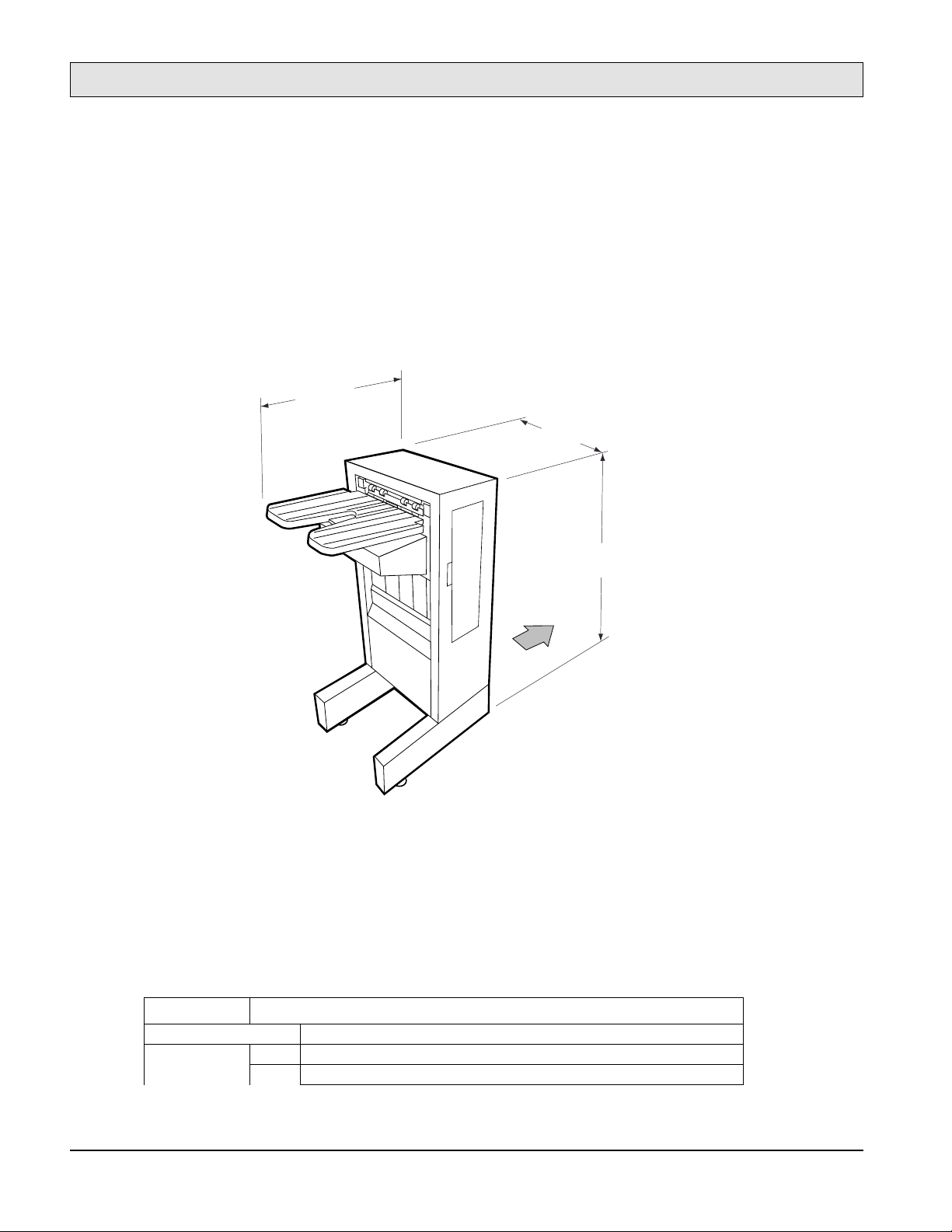
The 4060 non-impact printer combines semiconductor laser optical technology and twocomponent dry development process technology to print on cut-sheet plain paper. Figure 1-1
illustrates an installed printer and the external large capacity paper handling options.
LTR
LTR
LTR
LCS M3894SA LCH
Figure 1-1. 4060 Printer With Optional LCH and LCS Paper Handlers
1-3
General Information
SERVICE MANUAL
1-2. Printer Specifications
This section provides general, print speed, physical, electrical, environmental specifications as
well as safety standards applicable to all equipment and an illustration of the printer laser
equipment warning label.
1-2.1. Printer General Specifications
Table 1-1 lists general specifications for the 4060 printer.
Table 1-1. 4060 Printer General Specifications
Item Specifications
Printing technology Laser diode, Electro-photography
Printing speed 40 ppm (Letter and A4 landscape)
Paper Size Letter, Legal, Ledger. Executive, A3, A4, A5, B4 (JIS), B5 (JIS)
Type Plain Paper, Label paper, Recycle paper, Transparency paper, Bond paper, Pre-punched paper
Resolution 600 × 600 dpi
Paper capacity
Stacker capacity
3 trays × 500 sheets (64 g/m2) standard
•
1 tray × 500 sheets (64 g/m2) optional custom tray
•
3,000 sheets (A4, Letter size only) optional Large-Capacity Hopper (LCH)
•
500 sheets (64 g/m2) face down tray
•
2,000 sheets optional Large-Capacity Stacker (LCS)
•
1-2.2. Printer Print Speed Specifications
Table 1-2 lists the specifications for the 4060 printer print speeds.
Table 1-2. 4060 Printer Print Speed Specifications
Paper Size (direction) Simplex *2 Duplex *2
Letter (landscape) 40 40
Legal (portrait) 25 25
Ledger (portrait) 21 15
Executive (portrait) 40 40
A3 (portrait) 21 15
A4 (landscape) 40 40
A5 (portrait) 40 40
B4 (JIS) (portrait) 24 24
B5 (JIS) (portrait) 30 30
B4 (ISO) (portrait) *1 21 15
-4
B5 (ISO) (portrait) *1 40 40
Custom (paper width = 120mm to 297mm,
paper length = 182mm to 215.9mm) *1
Custom (paper width = 120mm to 297mm,
paper length = 215.9mm to 431.8mm) *1
Notes
:
*1: Can be fed from optional custom paper tray only.
*2: Unit of measure: Images Per Minute (IPM). All the speeds have ±5% tolerance.
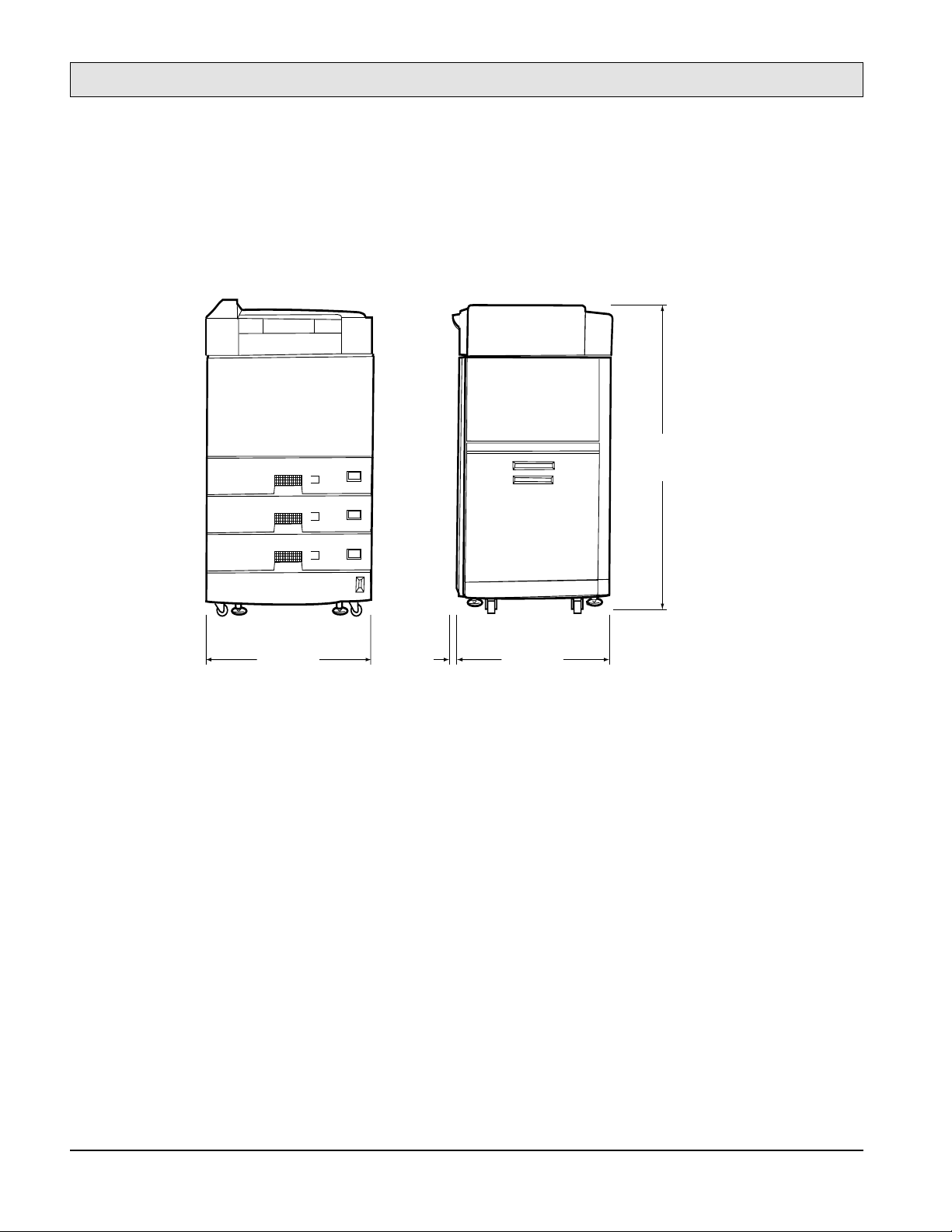
1-2.3. Printer Physical Specifications
Table 1-3 lists the printer physical specifications.
General Information
SERVICE MANUAL
24 24
34 34
Figure 1-2 illustrates the physical specifications and Figure 1-3 illustrates the required printer
service area dimensions.
Table 1-3. 4060 Printer Physical Specifications
Item Specification
Dimensions Width Depth Height
585 mm (23.0 in) 640 mm (25.2 in) 1,030 mm (40.6 in)
Weight Approximately 135 kg
Service area Front Back Left Right
650 mm (25.6 in) 850 mm (33.5 in) 850 mm (33.5 in) 850 mm (33.5 in)
1-2.4. Printer Electrical Specifications
Table 1-4 lists the printer electrical specifications.
Table 1-4. 4060 Printer Electrical Specifications
Item Specifications
Input power Voltage 120 to 127 VAC ± 10%, 12A
200 to 240 VAC ± 10% 7A
Phase Single-phase
Frequency 50/60Hz ±5%
Power consumption 1,300 VA or less than during operating
Heat capacity 894 kcal per hour
1-5
General Information
SERVICE MANUAL
40.5 in.
LTR
(1030 mm)
LTR
LTR
23.0 in.
(585 mm)
1.38 in
(35 mm)
25.2 in.
(640 mm)
Figure 1-2. 4060 Printer Physical Dimensions
-6
Printer
General Information
SERVICE MANUAL
33.5 in.
(850 mm)
84.3 in.
(2140 mm)
25.2 in.
(640 mm)
25.6 in.
(650 mm)
33.5 in.
(850 mm)
Operating
Side
23.0 in.
(585 mm)
90.0 in.
(2285 mm)
33.5 in.
(850 mm)
Figure 1-3. 4060 Printer Required Service Area Dimensions
1-2.5. Environmental Specifications For All Equipment
Table 1-5 lists environmental specifications applicable to the printer, LCH, and LCS units.
Table 1-5. 4060 Printer, LCH Option, and LCS Option Environmental Specifications
Item Specification
Ambient
Condition
Acoustic noise 55 dBA or less (printer only)
Dust
Ozone emission 0.1 PPM or less
Device condition Operating Non-operating
Temperature 10 to 35 °C 0 to 35 °C
Humidity 20 to 80% RH
(no condensation)
Temperature and
humidity gradients
15 °C per hour or less and 30% RH per day or
less (no condensation)
0.15 mg./m
3
(stearic acid)
20 to 80% RH
(no condensation)
1-3. Summary of Printer Optional Features and Feature Specifications
Table 1-6 lists the options available with the 4060 printer along with their associated
specifications.
1-7
General Information
SERVICE MANUAL
Table 1-6. 4060 Printer Available Options and Specifications Summary
Item Specification Model Number
Large-Capacity Hopper
(LCH)
Large-Capacity Stacker
(LCS)
Custom paper tray
3,000 sheets (75 g/m
2,000 sheets (75 g/m
500 sheets (75 g/m
2
)
2
)
2
)
4060 (Letter)
4060 (A4)
4060 (120 VAC)
4060 (240 VAC)
-8
1-4. Large-Capacity Hopper (LCH)
1-4.1. LCH Overview
General Information
SERVICE MANUAL
Models
4060
and
4060
are the user-installable optional Large-Capacity Hoppers (LCH) units for
the 4060 printer, connecting to the right side of the printer. The
only, and the
4060
can feed A4 size paper. Both LCHs can be installed up to 3000 sheets of paper
(75g/m2).
Figure 1-4 illustrates the Large-Capacity Hopper unit.
11.3 in.
(287 mm)
PRINTER
4060
can feed Letter size paper
17.6 in.
(446 mm)
Figure 1-4. Large-Capacity Hopper Physical Dimensions
1-4.2. LCH Paper Handling Specifications
Table 1-7 lists the LCH paper related specifications.
Table 1-7. LCH Paper Handling Specifications
Item Specifications
22.2 in.
(562 mm)
1-9

General Information
SERVICE MANUAL
Processing speed 40 ppm (4060: Letter landscape and 4060: A4 landscape)
Paper Size 4060: Letter and 4060: A4
Typ e
Paper capacity
Plain paper, Label paper, Transparency, Bond paper, Pre-punched paper 64 to 90g/m
3,000 sheets (75g/ m
2
)
1-4.3. LCH Physical Specifications
Table 1-8 lists the LCH physical dimensions, unit weight, and required service area dimensions
and Figure 1-4 illustrates these dimensions. Figure 1-5 illustrates the LCH service area
requirements.
Table 1-8. LCH Physical Specifications
Item Specification
Dimensions Width Depth Height
287 mm (11.3 in) 446 mm (17.6 in) 562 mm (22.2 in)
Weight About 17 kg (38 lbs)
Service area Front Back Right
650 mm (25.6 in) 850 mm (33.5 in) 850 mm (33.5 in)
2
-10
33.5 in.
(850 mm)
21.25 in.
(540 mm)
Printer LCHLCS
Operating
Side
23.0 in.
(585 mm)
122.6 in.
(3114 mm)
33.5 in.
(850 mm)
84.3 in.
(2140 mm)
25.2 in.
(640 mm)
25.6 in.
(650 mm)
33.5 in.
(850 mm)
11.38 in.
(289 mm)
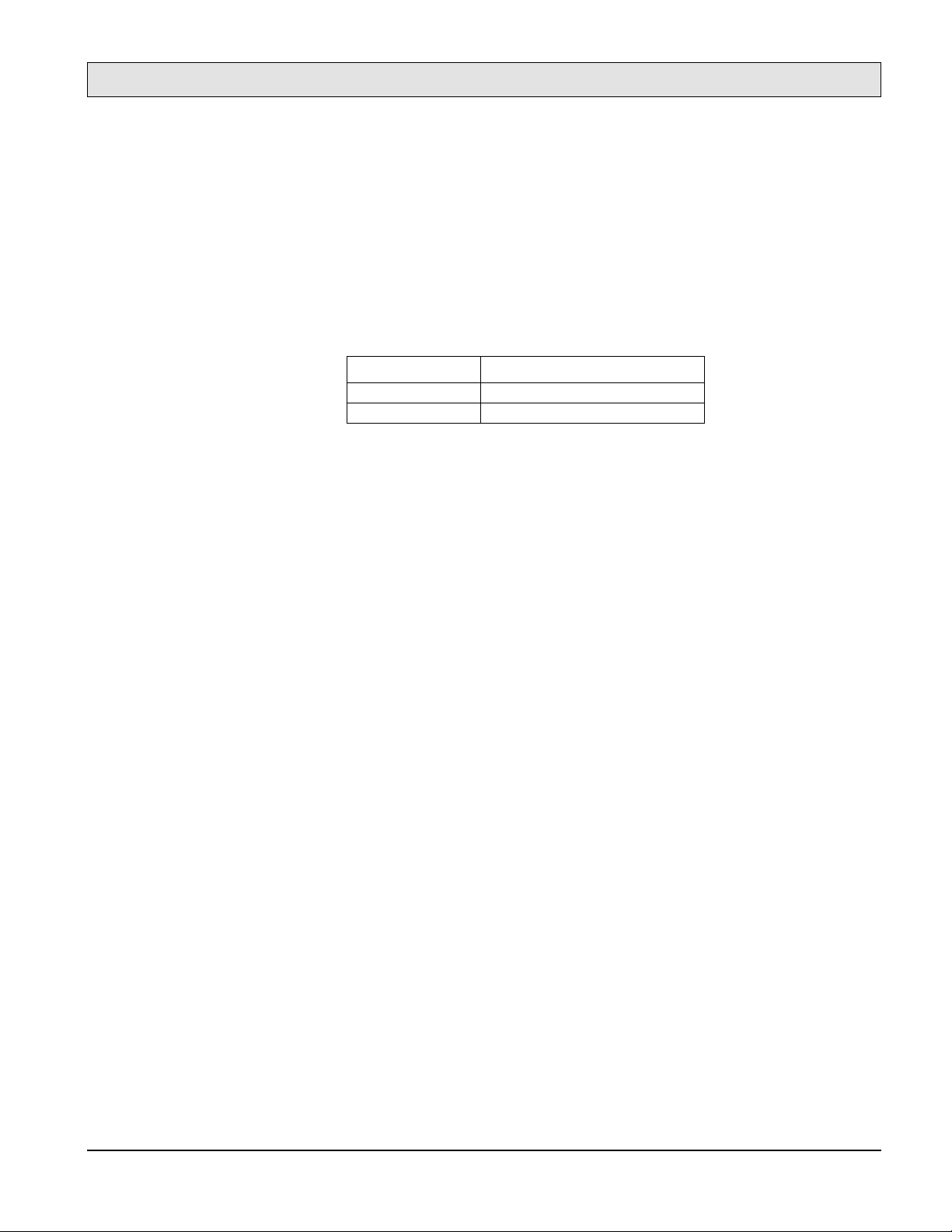
Figure 1-5. LCH, Printer, and LCS Required Service Area Dimensions
1-4.4. LCH Electrical Specifications
Table 1-9 lists the LCH electrical specifications.
Table 1-9. LCH Electrical Specifications
Item Specification
Input power 24VDC, supplied from 4060 printer
Power consumption 30VA or less during operation
1-4.5. LCH Environmental Specifications
General Information
SERVICE MANUAL
Refer to Table 1-5 for LCH environmental specifications.
1-11
General Information
SERVICE MANUAL
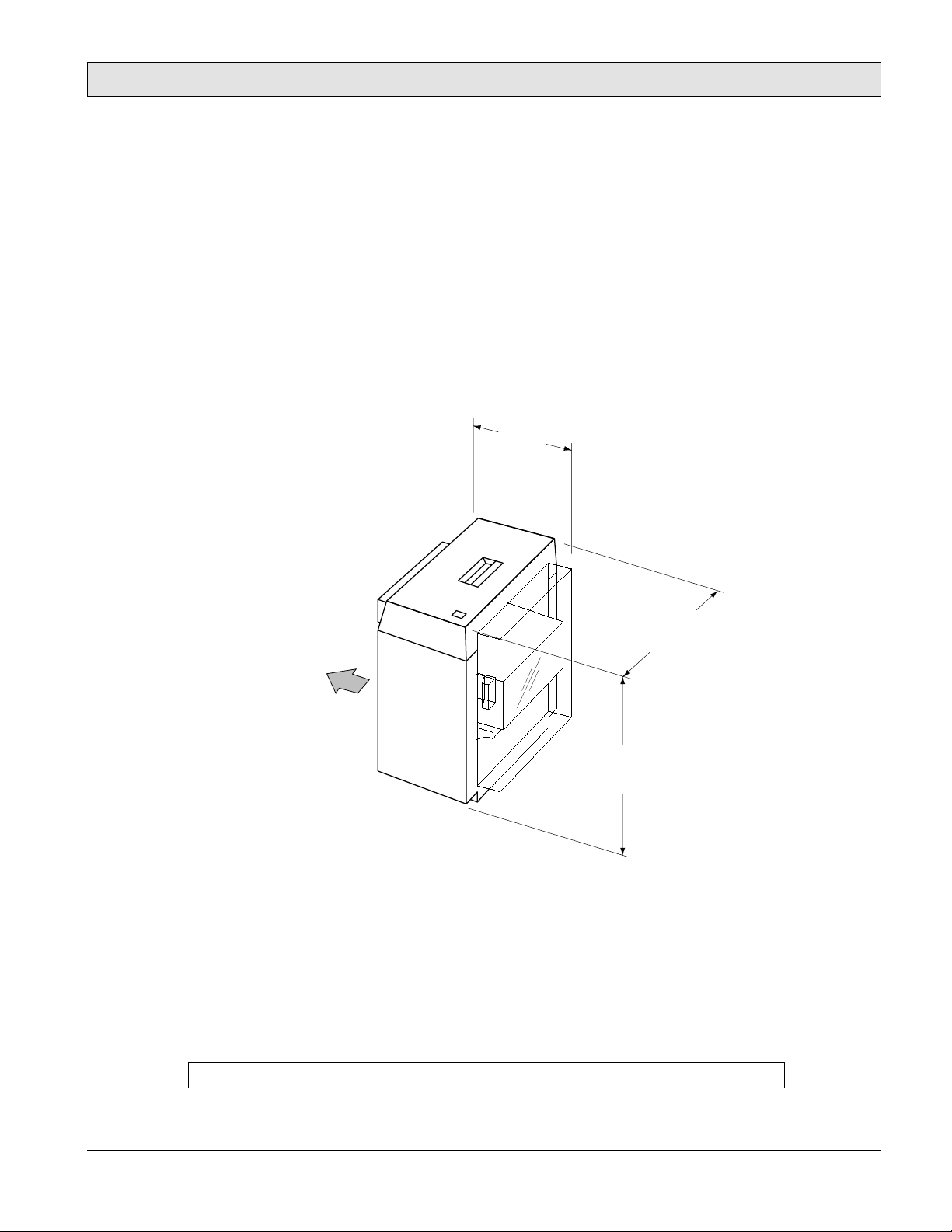
1-5. Large-Capacity Stacker (LCS)
1-5.1. LCS Overview
Figure 1-6 shows the user-installable optional Large-Capacity Stacker (LCS) paper handler that
connects to the left side of the printer. Model
4060
LCS can stack up to 2000 sheets of paper (75g/m2).
21 in.
(533 mm)
is for 120V, and model
17.4 in.
(442 mm)
4060
is for 240V. The
Figure 1-6. Large-Capacity Stacker Physical Dimensions
1-5.2. LCS Paper Handling Specifications
Table 1-10 lists the LCS paper handling specifications.
Table 1-10. LCS Paper Handling Specifications
36.0 in.
(913 mm)
PRINTER
-12
Item Specifications
Processing speed 40 ppm
Paper Size Letter, Legal, Ledger, Executive, A3, A4, A5, B4(JIS) (ISO), and B5 (JIS) (ISO)
Type Plain paper, Label paper, Transparency, Bond paper, Pre-punched paper 64 to 90g/m2
General Information
SERVICE MANUAL
Paper capacity 2,000 sheets (75g/ m2)
1-5.3. LCS Physical Specifications
Table 1-11 lists the LCS physical dimensions, unit weight, and also provides the required service
access area dimensions.
Figure 1-6 illustrates these specifications.
Table 1-11. LCS Physical Specifications
Item Specification
Dimensions Width Depth Height
533 mm (21 in) 442 mm (17.4 in) 913 mm (36.0 in)
Weight About 32 kg (70 lbs)
Service area
Front Back Left
650 mm (25.6 in) 850 mm (33.5 in) 850 mm (33.5 in)
1-5.4. LCS Electrical Specifications
Table 1-12 lists the LCS electrical specifications.
Table 1-12. LCS Electrical Specifications
Item
Input Power Voltage 100 to 120 VAC
±
Phase Single-phase
Frequency 50/60 Hz 5%
Power consumption 120 VA or less during operation
Heat capacity 83 kcal per hour
1-5.5. LCS Environmental Specifications
Table 1-5 lists the LCS environmental specifications.
Specification
4060 4060
10%
200 to 240 VAC
10%
±
1-13
General Information
SERVICE MANUAL
1-6. Printer Custom Paper Tray
Model 4060 printer custom paper tray is user-installable, optional custom paper tray for the 4060
printer that is compatible and switchable with the standard printer paper tray. The custom paper
tray can hold up to 500 sheets (75g/m2) of free sized paper as listed in Table 1-13 specifications.
Table 1-13. Custom Paper Tray Physical Specifications
Paper Size Inches Millimeters
Minimum 4.7 x 7.2 120 x 182
Maximum 11.7 x 17 297 x 431.8
Paper size information for the custom tray is selectable. The custom tray also supports the
following standard media sizes: Letter, Legal, Ledger, Executive, A3, A4, A5, B4 and B5.
The printing speed from the custom tray is listed in Table 1-2 (measured on and after the second
page in continuous printing mode).
1-7. Printer Consumable Specifications
This section explains how the replacement rate is established for the printer consumables. The
4060 User Manual
procedures.
Table 1-14 lists the consumables and their respective replacement cycle specifications. Ensure that
consumables are replaced at the recommended intervals by monitoring the usage of the printer.
Consumable Item Replacement cycle
Toner 20,000 images for continuous printing, with 4% coverage for each bottle (average 18,000 images)
Developer 1,600 drum count for each bottle (160,000 images for continuous printing, average 114,000 images)
Drum 2,500 drum count (250,000 images for continuous printing, average 178,500 images)
Transfer Charger 2,500 drum count (250,000 images for continuous printing, average 178,500 images)
Fuser 3,000 page length count (approx. 300,000 images)
Cleaning Roller 40,000 images for continuous printing with 4% coverage (average 36,000 images)
Ozone Filter 3,200 drum count (320,000 images for continuous printing, average 228,000 images)
Collector Bottle 20,000 images for continuous printing with 4% coverage (average 18,000 images)
Printer Pick Roller Kit 5,000 page length count each (approx. 500,000 images)
LCH Pick Roller Kit 5,000 page length count each (approx. 500,000 images)
provides details about consumables kit contents, ordering, and replacement
Table 1-14. Consumables and Replacement Cycle
Notes supporting Table 1-14:
(1) All the values for replacement cycle shown above are based upon printing on A4 size
paper.
-14
General Information
SERVICE MANUAL
(2) All the listed values are theoretical. The damage due to improper handling, maintenance,
papers, environments, and other uncontrollable occasions are not considered in these
values.
(3) All the values for replacement cycle/life shown above depends on printing usage’s and
conditions:
Drum Counts
•
: The drum counter will increment every 150 seconds (equals 100
images of A4 paper at continuous printing). This counter increments during
Warming-up, Intermittent printing and Auto-patrol sequence.
Calculation of the average printed images is based on 1/1.4 of continuous printing;
the combination of intermitted printing mode and continuous printing mode.
Page Length count
•
: The page length counter will increase after 100 simplex A4
images are stacked. On duplex printing the page length counter is incremented by
two.
For the Printer Pick Roller Kit and the LCH Pick Roller Kit, this counter always
increments as simplex printing. When another size paper is used, the counter
increments according to the Table 1-15 listed values.
Table 1-15. Page Length Count
Paper size
Letter 1 2
Legal 2 4
Ledger 2 4
Executive 1 2
A5 1 2
A4 1 2
A3 2 4
B4 (JIS) 2 4
B5 (JIS) 1.5 3
Increment by 100
sheets at simplex
printing
Increment by 100
sheets at duplex
printing
1-15

General Information
SERVICE MANUAL
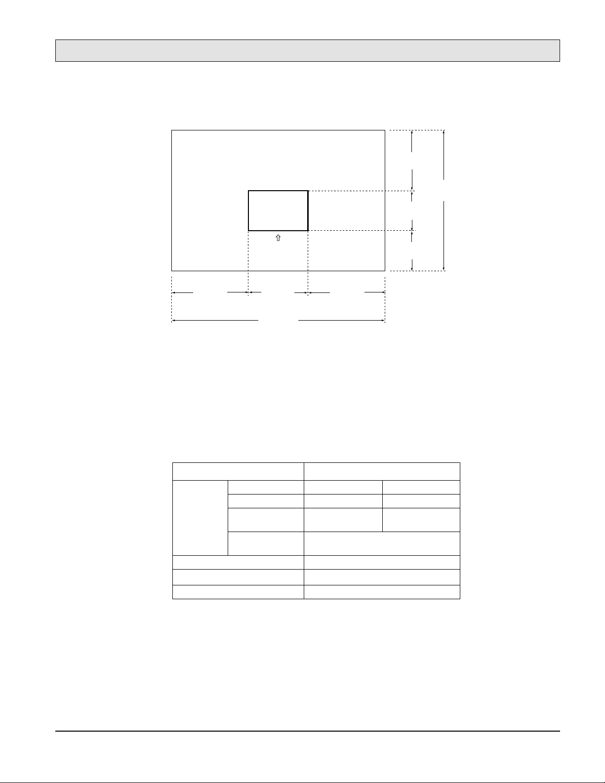
1-8. Best Printing Area Specifications
The printed images must be in an area within a 0.5 inch (12 mm) border. Printing outside of this
boundary may be of lower quality.
Figure 1-7 shows the best printing area.
Margin
Best area
Figure 1-7. Best Printing Area
If data is printed outside the best printing area, you may obtain poor print quality
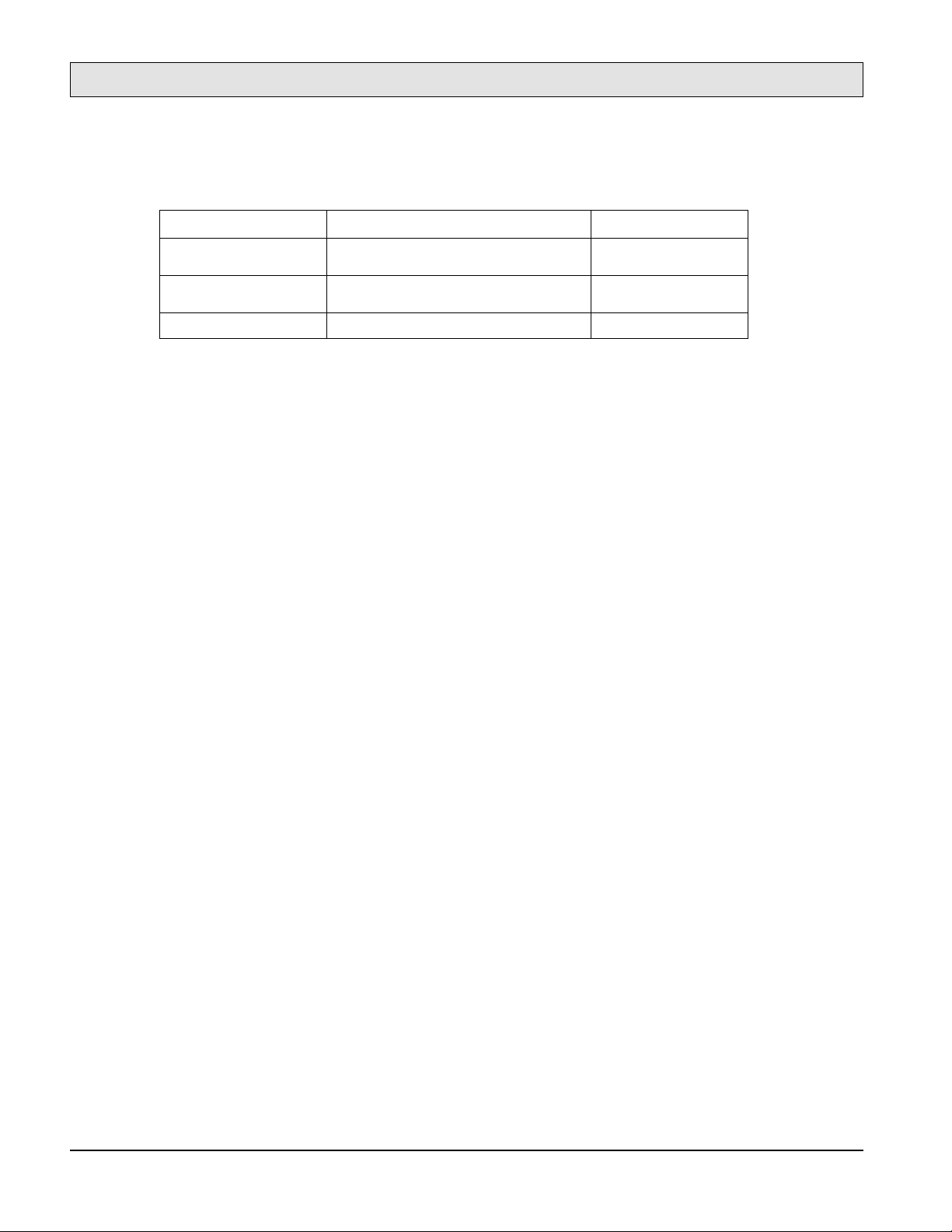
Figure 1-8 shows the print area of the 4060 printer.
ED
F
G
Feed direction
Paper
| D-E | 1.5 mm
| F-G | 1.5 mm
Figure 1-8. Print Area Specifications
If data is printed outside the printing-assured area as listed in Table 1-16 it will cause poor print
quality such as:
Paper feed skew (up to ±2mm) that may cause missing characters.
•
Bad paper transport that may cause a paper jam.
•
-16

Table 1-16. Print Area Specifications
A (mm) B (mm) A (mm) B (mm)
A5 139.6 201.6 LEDGER 271.0 423.4
A4 288.6 201.6 EXECUTIVE 175.75 258.3
A3 288.6 411.6 B5(JIS) 248.6 355.6
LETTER 271.0 207.5 B4 (JIS 173.6 248.6
LEGAL 207.5 347.2
Figure 1-9 shows the printing position precision.
General Information
SERVICE MANUAL
1-17

General Information
SERVICE MANUAL
– MAGNIFICATION
– SKEW
Ideal print area
H
I
A
Print area
Paper
| H-I | 2.5 mm
| J-K | 1.5 mm
J
K
Feed direction
Print section
Paper
| A-B | 2mm/432mm
-18
– OFFSET
B
Feed direction
ED
Paper
| D-E | 1.5 mm
| F-G | 1.5 mm
F
G
Figure 1-9. Print Positions
General Information
.
.
.
.
.
.
.
.
....
.
.
.
.
.
.
SERVICE MANUAL
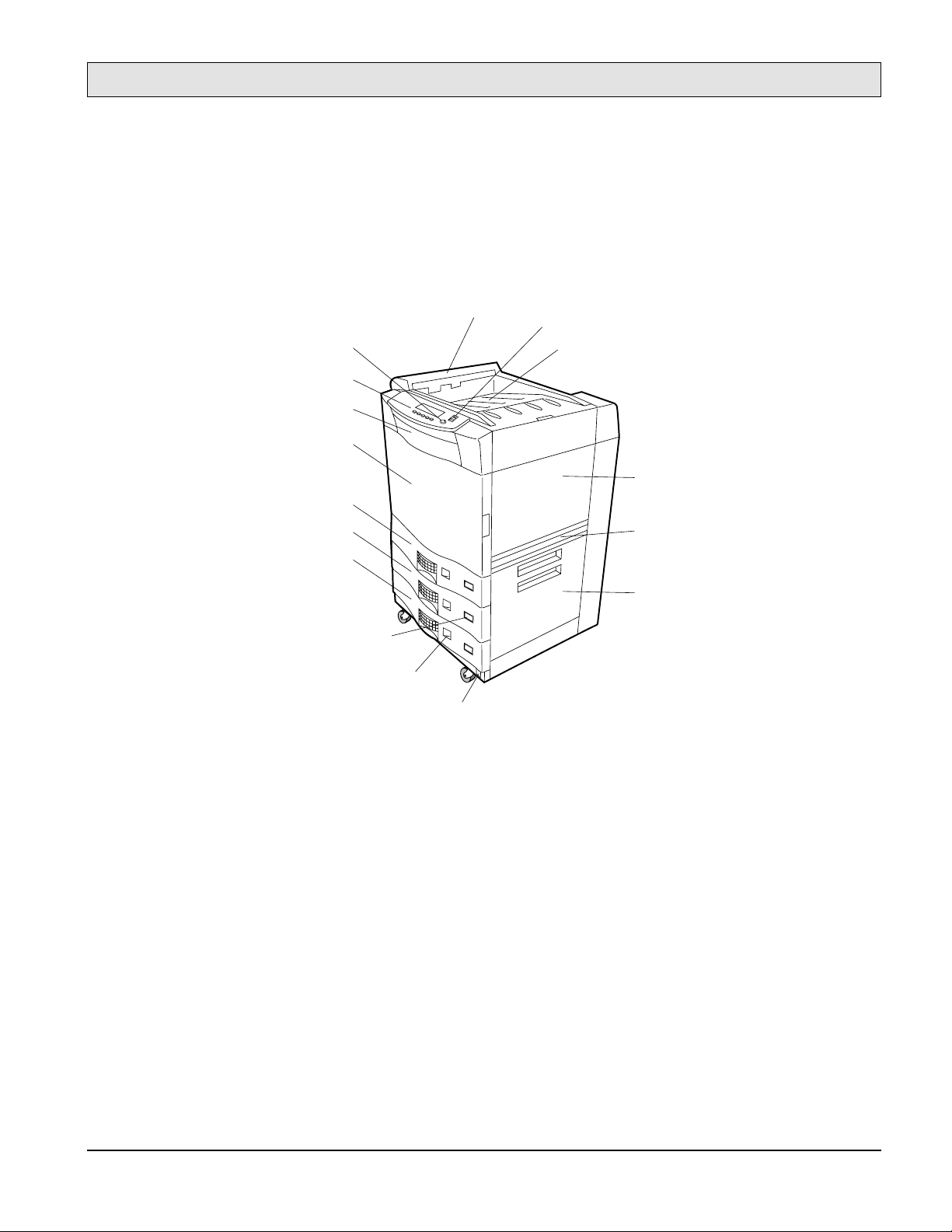
1-9. System Configuration Component Locations and Descriptions
1-9.1. Front and Right Side of the Printer
Ejection unit
Standby switch
Display contrast
Control panel
Front cover
Front door
Tray1
Paper stacker shelf
Upper right cover
Tray2
Tray3
Paper size indicators
Paper level indicators
Main power switch
LCH cover
Lower right cover
Figure 1-10. Front and Right Side of the Printer
The front of the printer contains the Control Panel and the controls most often used. In Figure 110, starting at the Control Panel at the top left and reading clockwise, refer to the following points
of interest:
The
•
•
Control Panel
as the LCD display) that presents messages about printer activity.
The
Display contrast
consists of function buttons and a liquid crystal display (also referred to
allows you to adjust the brightness of the LCD display.
The
•
•
•
•
Ejection unit
The
Standby switch
The
Paper stacker shelf
The
Upper right cover
deposits paper on the paper stacker shelf.
readies the printer for printing.
holds printed pages.
provides access to the toner and developer areas.
1-19
General Information
.
.
.
.
.
.
.
.
....
.
.
.
.
.
.
SERVICE MANUAL
The
•
•
•
•
•
•
LCH cover
The
Lower right cover
The
Paper size indicators
The
Main power switch
The
Paper level indicators
The
Trays 1, 2, and 3
should be exchanged to the paper input guide when LCH is installed.
covers the paper path from the paper trays.
show what size of paper is in each tray.
applies power to the printer.
tell you the amount of paper in the paper trays.
hold the printer’s standard paper supply. You can also obtain and
install optional adjustable custom trays that hold custom sizes of paper.
The
•
•
Front door
The
Front cover
provides access to the printer’s interior.
provides access to the printer’s floppy disk drive bay.
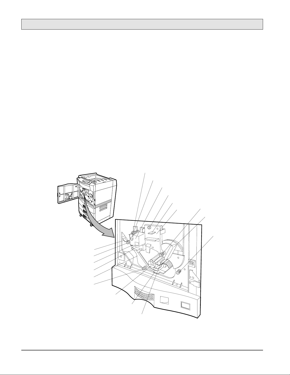
1-9.2. Behind the Front Door
Fuser locking knob
Cleaning roller
Fuser unit
Drum unit locking knob
Precharger cleaner
Drum unit
Knob 2
Lever b1
-20
Lever 5
Decurler roller knob
Decurler lever
Lever 4
Duplex unit
Duplex roller knob
Handle 3
Lever 6
Transfer unit
Figure 1-11. Behind the Front Door
Knob 1
LTR

General Information
SERVICE MANUAL
When you open the front door of the printer, you see the printer internal components shown in
Figure 1-11:
The
•
Fuser unit
fuse the toner to the paper.
The
•
Drum unit
cleaning unit.
The
•
Transfer unit
paper from the drum.
The
•
Duplex unit
ing.
The
•
•
•
•
Cleaning roller
The
Drum unit locking knob
The
Decurler roller knob
The
Duplex roller knob
sided printing).
•
•
•
Knob 1
Knob 2
Handle 3
is used to clear paper jams as the paper exits the paper trays and enters the drum area.
is used to clear paper jams as the paper exits the paper trays and enters the drum area.
lowers the transfer assembly guide to clear paper jams in the drum area.
applies heat and pressure to the paper using upper and lower rollers which
contains the precharger, photoconductor drum, precharger cleaner, and toner
moves the print image from the drum to the paper and then separates the
reverses and transports the paper to the printing unit for double sided print-
lubricates and collects excess toner on the fuser roller.
secures the drum.
is used to clear paper jams in the immediate area.
is used to clear paper jams in the duplex paper path (during double-
Decurler lever
•
Lever b1
•
Lever 4
•
Lever 5
•
Lever 6
•
provides access to paper in the decurler area to clear paper jams.
sets and release the developer unit when the drum or developer unit is removed.
releases tension on paper in the fuser area to clear paper jams.
provides access to paper in the reverser area to clear paper jams.
provides access to paper in the duplexer area to clear paper jams.
1-21
General Information
.
.
.
.
.
.
.
.
....
.
.
.
.
.
.
SERVICE MANUAL
1-9.3. Behind the Upper Right Cover
Toner hopper
Toner collector bottle
Developer collector bottle
Developer unit
Upper right cover
Figure 1-12. Behind the Upper Right Cover
By opening the upper right cover, you gain access to the printer’s consumables, as shown in Figure
1-12:
The
•
Toner hopper
contains a supply of toner. The Control Panel notifies you through the
controller when the toner supply is running low, and when the printer is out of toner.
The
•
Developer unit
contains a supply of developer that, when mixed with toner, forms the
visual image on the photoconductor drum. The Control Panel notifies you through controller
when the developer life is over.
The
•
This bottle is the empty bottle after suppling the new developer.
•
The
•
Developer collector bottle
Toner collector bottle
collects used toner for disposal.
collects used developer for disposal.
-22

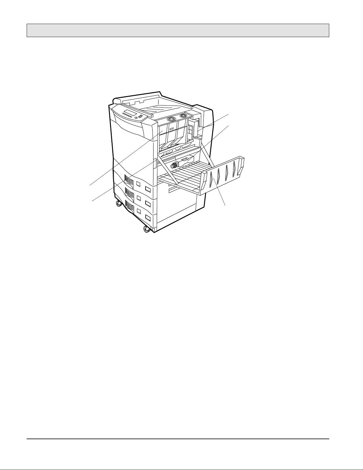
1-9.4. Behind the Lower Right Cover
General Information
SERVICE MANUAL
Upper paper feed unit
Middle paper feed unit
Lower paper feed unit
Figure 1-13. Printer Lower-right Side View
By opening the lower right cover, you gain access to the paper feed units as shown in Figure 1-13:
The
•
Upper, Middle, and Lower paper feed units
feed paper picked from the three paper
trays.
1-23

General Information
SERVICE MANUAL
1-9.5. Rear and Left Side of the Printer
Main controller
(Under top cover)
Optical unit
(Under main controller)
Ejection unit
Upper left cover
LCS cover
Ozone filter
LCH connector
AC input
power connector
LCS connector
Lower connector
not used
Figure 1-14. Rear and Left Side of the Printer
The rear of the printer has the features shown in Figure 1-14:
The
•
•
Ozone filter
The
Ejection unit
inhibits ozone exhaust.
ejects the paper to paper stacker and this cover of unit can be opened to
clear paper jams in this area.
The
•
LCS cover
provides access to the LCS paper path (if installed).
LCS attachment
points (under covers)
-24

SERVICE MANUAL
The LCS cover should be exchanged to the paper exit guide when LCS is installed.
•
General Information
The
•
•
•
•
LCS attachment covers
The
LCS connector
The
Lower connector
The
AC input power connector
provides an LCS cable interface (if installed).
is for future upgrades.
conceal LCS securing hardware.
can accept either 120-127 or 200-240 VAC input power
(fuser unit must be matched to the input voltage).
The
•
•
LCH connector
The
Optical unit
provides an LCH cable interface.
(located underneath the main controller) consists of two semi-conductor
laser diodes and a rotating mirror spindle motor and lens. The laser generator outputs dualbeams from the laser diodes.
1-25

General Information
SERVICE MANUAL
1-9.6. Rear-Inside of the Printer
Drive unit E
Drive unit D
Drive unit M
High voltage
power supply
RN101
ACN4J
CNFAN2
CNFAN1
DCNJ10
DCNJ1DCNJ2
DCNJ9
DCNJ6
DCNJ5
DCNJ3
Low voltage power supply
(Behind Mechanism
Controller Board)
CN7
PC Board
CN5
CN6
CN8
CN9
CN10
PC Board
CN11
CN12
Mechanism Controller
Board
CN14
CN13
Figure 1-15. Printer Rear Inside View
The rear of the printer has the features shown in Figure 1-15:
•
•
-26
The
Drive unit D
The
Drive unit E
controls toner feed drive screw for toner flow control.
controls the ejection unit feed belt.

General Information
SERVICE MANUAL
The
•
•
Drive unit M
The
High voltage power supply
controls the printer print unit.
develops and regulates high voltages to the drum unit
components (precharger, photoconductor drum, and cleaning unit), the transfer assembly
components (transfer charger and AC charger) and the developer unit.
The
•
Low voltage power supply
develops and regulates low voltages used by the motors
and the control circuits and so on.
The
•
Mechanism controller
contains the control circuits which control the mechanical
movement of paper through the printer.
1-9.7. Large-Capacity Hopper (LCH)
LCH release handle
Paper shelf lowering button
LCH door
Door handle
PRINTER
Figure 1-16. Large-Capacity Hopper
Paper shelf
The cut sheet printer can also load paper from the optional Large-Capacity Hopper (LCH)
accessory (shown in Figure 1-16). The LCH sits on rails attached to the printer and is electrically
connected to the printer by a cable, and obtains its power from the printer. The LCH highlights are:
The
•
•
LCH release handle
The
Paper shelf lowering button
, when squeezed, detaches the LCH from the printer.
, when pressed, lowers the shelf for paper replenish-
ment.
1-27

General Information
SERVICE MANUAL
The see-through
•
The
•
•
Door handle
The elevator-type movable
LCH door
provides easy access to the paper supply.
allows visual inspection of the paper supply.
Paper shelf
1-9.8. Large-Capacity Stacker (LCS)
supports the paper supply.
ON
OFF
Main Power Switch
Input power cord connector
LCS Interface
control cable
Figure 1-17. Large-Capacity Stacker
The cut sheet printer can stack paper onto the optional Large-Capacity Stacker (LCS) accessory
stacker (shown in Figure 1-17). The LCS uses a standard power cord that may be plugged into any
wall outlet. The LCS is mechanically connected to the printer and is electrically connected to the
printer by a cable. Power is controlled by the ON/OFF switch.
-28
 Loading...