


CONTENTS
CONTENTS
SAFETY AND IMPORTANT
WARNING ITEMS ................................................. C-1
IMPORTANT NOTICE........................................... C-1
DESCRIPTION ITEMS FOR DANGER,
WARNING AND CAUTION ................................... C-1
SAFETY WARNINGS ........................................... C-2
SAFETY INFORMATION ...................................... C-4
SAFETY CIRCUITS .............................................. C-5
INDICATION OF WARNING
ON THE MACHINE ............................................... C-6
1. GENERAL DESCRIPTIONS
1.1 SPECIFICATIONS ........................................... 1-1
1.1.1 Unit specifications ..................................... 1-1
1.1.2 Printer controller specifications.................. 1-2
1.2 OPTIONS ......................................................... 1-3
1.2.1 Paper deck (PD-101)................................. 1-3
1.2.2 Paper cassette LG..................................... 1-3
1.2.3 Printer controller option ............................. 1-3
2. OPERATION
2.1 OPERATION METHOD of KL-3015................. 2-1
3. OUTLINE OF SYSTEM FUNCTION
3.1 PROCESS ........................................................ 3-1
3.1.1 Image writing ............................................. 3-1
[1] Overview ................................................... 3-1
[2] Structure and function of the write unit....... 3-1
3.1.2 Forming the image .................................... 3-3
[1] Image forming process .............................. 3-3
[2] Process description ................................... 3-4
3.1.3 Fixing......................................................... 3-7
[1] Overview ................................................... 3-7
3.2 MECHANICAL SECTION................................. 3-8
3.2.1 Center cross sectional view/Laser
beam path ................................................. 3-8
[1] Center cross sectional view ....................... 3-8
[2] Laser beam path ....................................... 3-8
3.2.2 Electronic parts layout ............................... 3-9
[1] Circuit boards layout, display layout .......... 3-9
[2] Motor - solenoid - heater layout ............... 3-10
[3] Switch, sensor layout .............................. 3-11
3.2.3 Drive system diagram.............................. 3-12
[1] Main motor drive section 1 ...................... 3-12
[2] Main motor drive section 2 ...................... 3-13
[3] Paper feed section .................................. 3-14
[4] Developing drive section 1 ...................... 3-15
[5] Developing drive section 2 ...................... 3-16
[6] Toner supply section ............................... 3-17
[7] Cleaning blend/transfer roller
Drive section ........................................... 3-18
3.3 OPERATION AND CONTROL....................... 3-19
3.3.1 Write section............................................ 3-19
[1] Write unit structure .................................. 3-19
[2] Write section operation ............................ 3-19
[3] Write section control ................................ 3-20

CONTENTS
3.3.2 Paper feed section .................................. 3-22
[1] Paper feed section layout ........................ 3-22
[2] Paper feed unit structure ......................... 3-22
[3] Paper feed operation ............................... 3-23
[4] Paper feed section control ....................... 3-25
3.3.3 Drum cartridge......................................... 3-27
[1] Drum cartridge structure.......................... 3-27
[2] Drum cartridge operation ......................... 3-27
[3] Drum section control ............................... 3-29
3.3.4 Developing section .................................. 3-32
[1] Developing section structure ................... 3-32
[2] Developing unit operation ........................ 3-32
[3] Developing section control ...................... 3-34
3.3.5 Toner supply unit..................................... 3-37
[1] Toner supply unit structure ...................... 3-37
[2] Toner supply section operation................ 3-37
[3] Toner supply unit control ......................... 3-39
3.3.6 Transfer unit ............................................ 3-40
[1] Transfer unit structure ............................. 3-40
[2] Transfer conveyor section operation ....... 3-40
[3] Controlling the transfer section ................ 3-42
3.3.7 Fixing and paper exit section................... 3-44
[1] Configuration of fixing and
paper exit section .................................... 3-44
[2] Operation of the fixing and
paper exit section .................................... 3-44
[3] Control of the fixing section ..................... 3-45
4. DISASSEMBLY AND REASSEMBLY
4.1 DISASSEMBLY PROCEDURES...................... 4-1
4.1.1 Cautions During Disassembly and
Reassembly .............................................. 4-1
4.1.2 DISASSEMBLY PROCEDURE
FLOWCHART ........................................... 4-2
4.2 DISASSEMBLY AND ASSEMBLY .................. 4-4
4.2.1 Printer Controller Unit................................ 4-4
[1] Removing and installing the printer
controller unit............................................. 4-4
4.2.2 Outer Section ............................................ 4-5
[1] Removing and installing
the outer section........................................ 4-5
[2] Removing the multi feed tray ..................... 4-7
[3] Removing the operation panel ...................4-7
[4] Removing the shield box ........................... 4-8
4.2.3 Toner Supply Unit...................................... 4-9
[1] Replacing the toner bottle .......................... 4-9
[2] Removing and installing
the toner supply unit .................................. 4-9
4.2.4 Write Unit ................................................ 4-11
[1] Removing and installing the write unit ..... 4-11
[2] Cleaning the anti-dust glass .................... 4-12
4.2.5 Main Drive Unit........................................ 4-13
[1] Removing the humidity sensor PCB ........ 4-13
[2] Removing the main drive unit .................. 4-13
4.2.6 Paper Feed Section................................. 4-14
[1] Replacing the paper feed pick up roller ... 4-14
[2] Replacing the multi feed pick up roller ..... 4-14
[3] Removing and installing
the paper feed unit................................... 4-14
[4] Disassembly and reassembly of
paper feed section................................... 4-15
4.2.7 Fixing Unit ............................................... 4-17
[1] Removing and installing the fixing unit..... 4-17
4.2.8 High Voltage Power Source..................... 4-18
[1] Installing and removing the high voltage
power source........................................... 4-18
4.2.9 Engine Controller PCB ............................ 4-19
[1] Removing and installing
the engine controller PCB........................ 4-19
4.2.10 Drive Unit............................................... 4-20
[1] Removing and installing the drive unit ..... 4-20
4.2.11 Main Cooling Fan/Ozone
Regulation Cover................................... 4-20
[1] Removing and installing
the main cooling fan ................................ 4-20
[2] Installing and removing
the ozone regulation cover ...................... 4-20
4.1.12 DC power source................................... 4-21
[1] Removing and installing
the DC power source............................... 4-21
4.2.13 Paper Exit Unit....................................... 4-21
[1] Removing and installing
the paper exit unit .................................... 4-21
4.2.14 Other sections ....................................... 4-22
[1] Removing the main unit relay PCB .......... 4-22
[2] Removing the paper size sensor PCB ..... 4-22

CONTENTS
5. ADJUSTMENT
5.1 ADJUSTMENT ................................................. 5-1
5.2 ENGINE I/O CHECK MODE............................. 5-2
5.2.1 Using the Engine I/O check mode ............. 5-2
5.2.2 I/O check code list (input).......................... 5-3
5.2.3 I/O check list (output) ................................ 5-5
5.2.4 Multi code list............................................. 5-6
5.3 ENGINE NVRAM SERVICE MODE ................. 5-8
5.3.1 Using the Engine NVRAM service mode ... 5-8
5.3.2 Address map table in mode 25 .................. 5-9
6. DIAGRAMS
6.1 OVERALL WIRING DIAGRAM ........................ 6-1
Overall wiring diagram (1/2)................................ 6-1
Overall wiring diagram (2/2)................................ 6-2
6.2 CIRCUIT DIAGRAM......................................... 6-3
Printer controller PCB circuit diagram (1/6)......... 6-3
Printer controller PCB circuit diagram (2/6)......... 6-4
Printer controller PCB circuit diagram (3/6)......... 6-5
Printer controller PCB circuit diagram (4/6)......... 6-6
Printer controller PCB circuit diagram (5/6)......... 6-7
Printer controller PCB circuit diagram (6/6)......... 6-8
Operation PCB circuit diagram ........................... 6-9
LD drive PCB circuit diagram............................ 6-10
Paper feed PCB circuit diagram ....................... 6-11
Motor control PCB circuit diagram .................... 6-12
Polygon drive PCB circuit diagram ................... 6-13
Main unit relay PCB circuit diagram.................. 6-14
DC Power source circuit diagram ..................... 6-15
PCL PCB circuit diagram .................................. 6-16
Discharging lamp PCB circuit diagram ............. 6-17
Paper size sensor PCB circuit diagram ............ 6-18
INDEX sensor PCB circuit diagram .................. 6-19
Density sensor PCB circuit diagram ................ 6-20
Humidity sensor PCB circuit diagram ............... 6-21
Toner density sensor (Y) circuit diagram .......... 6-22
Toner density sensor (M) circuit diagram.......... 6-23
Toner density sensor (C) circuit diagram .......... 6-24
Toner density sensor (K) circuit diagram .......... 6-25
Developing relay PCB 1 circuit diagram ........... 6-26
Developing relay PCB 2 circuit diagram ........... 6-27
Developing relay PCB 3 circuit diagram ........... 6-28
Developing relay PCB 4 circuit diagram ........... 6-29
Developing relay PCB 5 circuit diagram ........... 6-30
Drum unit relay PCB circuit diagram................. 6-31
6.3 ERROR MESSAGE........................................ 6-32
6.4 TIMING CHART ............................................. 6-37
Timing chart 1 ( Warm up ) ................................. 6 - 37
Timing chart 2 (1/2) ............................................ 6 - 38
Timing chart 2 (2/2) ............................................ 6 - 39
Timing chart 3 (1/2) ............................................ 6 - 40
Timing chart 3 (2/2) ............................................ 6 - 41
Timing chart 4..................................................... 6 - 42
Timing chart 5..................................................... 6 - 43
Timing chart 6 (1/4) ............................................ 6 - 44
Timing chart 6 (2/4) ............................................ 6 - 45
Timing chart 6 (3/4) ............................................ 6 - 46
Timing chart 6 (4/4) ............................................ 6 - 47
7. CONSUMABLES INSTALLATION
Drum Cartridge Installation Manual .................... 7-1
Black Developer Unit Installation Procedure....... 7-5
Color Developer Unit Installation Procedure ....... 7-9
Transfer Maintenance Kit (Transfer unit/Oil roller
unit) Installation Procedure............................... 7-13

1
GENERAL DESCRIPTIONS

1.1 SPECIFICATIONS
GENERAL DESCRIPTIONS
1.1.1 Unit specifications
a. Basic specifications
Type: Non-impact Page Printer
Imaging method : Laser indirect electrostatic method
(KNC Process)
Lamp source : Semiconductor laser
Light sensitive medium :
OPC drum
Developer : Dry type, 2 components
(Yellow, Magenta, Cyan, Black)
Resolution : 600 dpi x 600 dpi
Warm-up time : Approx. 190 seconds.
Maximum print size:
Color:
Letter (8.5" x 11" / 216 mm x 279
mm) or A4 (210 mm x 297 mm)
Monochrome:
Legal (8.5" x 14" / 216 mm x 356
mm)
Minimum print size: Color / Monochrome:
Postcard ( 100 mm x 148 mm)
Fixing method: Heat roller
Output method: Face-down output: 250-sheet stack
Face-up output: 10-sheet stack
Output selection: Manual switching of
face-up tray open/
close
First printout time:
Mode Standard OHT
paper feed tray
Size FU FD FU
A4
Letter
Executive
Legal
Monocolor
Full color 33 sec 35 sec 80 sec
Monocolor
Full color 32 sec 34 sec 80 sec
Monocolor
Full color 32 sec 34 sec Monocolor
Full color - - -
26 sec 28 sec 70 sec
25 sec 27 sec 70 sec
25 sec 27 sec -
26 sec 28 sec -
multi feed tray
Continuous print speed:
Mode Standard OHT
paper feed multi feed multi feed
Size tray tray tray
A4 Monocolor 15 ppm 7.8 ppm 1 ppm
Full color 3 ppm 2.8 ppm 1 ppm
Letter Monocolor 15 ppm 7.8 ppm 1 ppm
Full color 3 ppm 2.8 ppm 1 ppm
Executive Monocolor 15 ppm 7.8 ppm -
Full color 3 ppm 2.8 ppm -
Legal Monocolor 13 ppm 7.8 ppm -
Full color - - -
Feed direction : Vertical (portrait)
Paper feed : Paper feed tray (64-90 g/m2 / 17-24 lb)
Letter, Executive, A4, B5 (Approx.
250 sheets)
Multi-feed tray (64-116 g/m2/17-36 lb)
Letter, Legal, Executive, A4, B5,
A5 (Approx. 50 sheets)
Postcards, OHT (Approx. 20 sheets)
Envelopes (Approx. 5 sheets) ,
Labels (5 mm stack)
500-sheet paper feed tray (PD-101)
(64-90 g/m2 / 17-24 lb)
Letter, A4 (Approx. 500 sheets)
Paper cassette LG (64-90 g/m2/17-24 lb)
Legal (Approx. 250 sheets)
b. Control panel
6 keys
3 LEDs
16 column 2 line LCD
FD : Face-down tray
FU : Face-up tray
Note : We reserve the right to make changes without prior notice for the purpose of product specification improvements.
1 - 1

GENERAL DESCRIPTIONS
c. Machine Specifications
Outer dimensions : W: 18.7" (476 mm) x D: 18.6" (472
mm) x 14.7" (374 mm)
Depth: 30.8"(782 mm) (When multi-
tray and face-up output tray are
released)
Weight : Approx. 30kg (Excluding print paper)
Power : 120 V 60 Hz
220 V / 230 V / 240 V 50 Hz
Power consumption :Max.1080 W / 120 V Model
Max.1380 W/220V,230V,240V Model
45 W or less (at Power Save mode)
Sound pressure level:Printing: 62 dB; Standby: 47 dB
Machine life: 500,000 prints (Monocolor) / 250,000
prints (Color) or five years whichever
comes earlier
Replacement parts: Fixing unit (Every 120,000 prints)
Paper feed roller of the Paper feed tray
(Every 120,000 prints)
d. Operating environment
Temperature : 10 °C to 32.5 °C
Humidity : 15 % to 80 %RH (no moisture)
1.1.2 Printer controller specifications
CPU : MIPS R4300
Frequency: 133 MHz
ROM : 8 Mbyte DIMM (PCL5C)
16 Mbyte DIMM (PCL5C and
PostScript: option)
RAM : 16 Mbyte DIMM (standard)
Max. 96 Mbyte (Upgrade Memory
8 MB/16 MB/32 MB)
PDL : PCL5C compatible
PostScript Level 3 (option)
Internal font : Roman 46Fonts (PCL5C: standard)
Roman 136 Fonts (PostScript Level 3:
option)
Interface : IEEE 1284 compliant parallel port
(Centronics/Byte / ECP)
Amphe.36 pins
Language displays: USA: English
Europe: English, French, Italian,
German, Spanish
Other options : Ethernet Card (EC-101)
AUI (10 Base 5)
RJ45 (10 Base-T / 100 Base-TX)
Token Ring card (TC-101)
RJ45 (UTP), DB9 (STP)
Hard disk drive (HD-101)
PostScript DIMM (PS-101)
Note : We reserve the right to make changes without prior notice for the purpose of product specification improvements.
1 - 2
1.2 OPTIONS
GENERAL DESCRIPTIONS
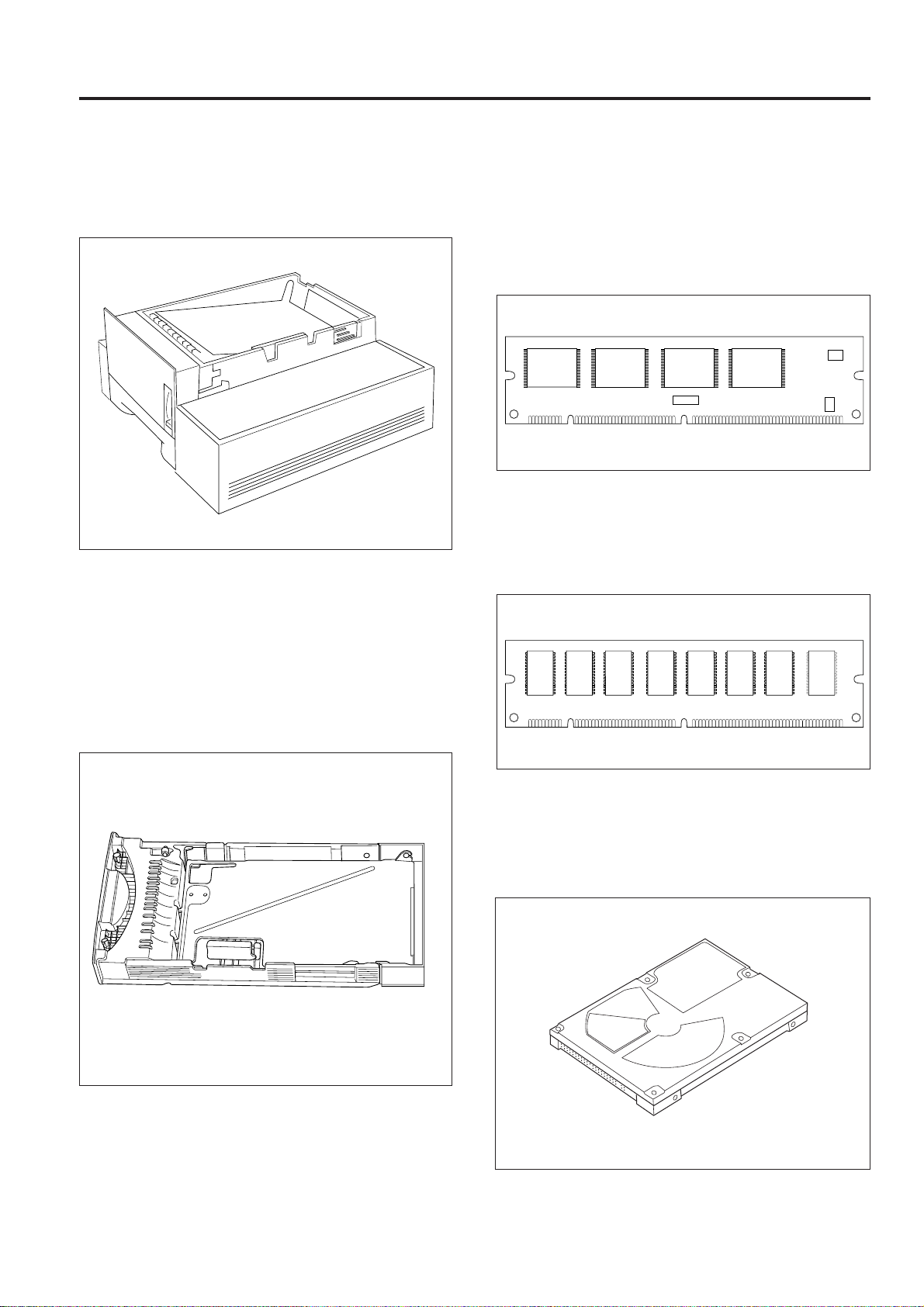
1.2.1 Paper deck (PD-101)
The paper deck installs beneath the KL-3015 unit and can
supply 500 A4 or Letter size paper sheets.
When the paper deck is installed, the 250 sheet tray that
comes with the main unit as standard equipment installs on
the lower side of the paper deck and the 500 sheet tray
installs on the upper side (main unit side).
1.2.3 Printer controller option
a. PostScript DIMM (PS-101)
Adobe PostScript Level 3 is available as a PDL for optional
use.
This installs in place of the ROM DIMM on the printer
controller board.
b. RAM DIMM
This installs in the DIMM socket on the printer controller
board and allows expanding the printer controller RAM
capacity to a maximum of 96 Mbytes.
1.2.2 Paper cassette LG
The paper cassette LG is a custom tray for legal size paper
and replaces the tray 250 that comes with the main unit as
standard equipment.
c. Internal hard disk (HD-101)
This is a 2.5 inch 1400 Mbyte IDE type hard disk that installs
direction in the IDE interface on the printer controller board.
The internal hard disk is used for print job spooling (PCL,
PostScript) and download font storage (PostScript).
1 - 3

GENERAL DESCRIPTIONS
d. Ethernet interface card (EC-101)
This is a optional card to add the Ethernet interface function
to the printer controller board and allows to use KL-3015 as a
network printer.
This card is equipped with a 100Base-TX / 10Base-T
connector and an AUI interface connector.
e. Token Ring interface card (TC-101)
This is a optional card to add the Token Ring interface
function to the printer controller board and allows to use KL3015 as a network printer.
1 - 4

2
OPERATION

OPERATION
2.1 OPERATION METHOD of KL-3015
As for the operation method of KL-3015, make use of the following manners and KL-3015 test print function.
NO.
1
Operation Panel Function
2
Menu Help
3
Printer Setup
4
Network Setup
5
Driver Install
6
Color Management
7
Using Fiery Web Tool
8
Consumable replacement
9
Printing from Applications
10
Printing pages from Operation Panel
Items
Getting Started Network Setup User's Manual CD-ROM Test print
2 - 1

3
OUTLINE of SYSTEM FUNCTION

3.1 PROCESS
OUTLINE of SYSTEM FUNCTION
3.1.1 Image writing
[1] Overview
The print data from the computer sent to the PRNCB (printer
controller) as PCL or PostScript draw command.
The PRNCB analyzes the draw command and makes picture
image into the memory, these are divided to CMYK each
Draw command
(PCL or PostScript)
Computer
PRNCB Write unit
Image data
per pixel
ENGCB
colors. The image data sent from the PRNCB is PWM
processed inside the ENGCB (engine controller) and output
as pulse signals to drive the LD (laser diode) of the write unit.
The laser beam from the LD is beamed as a scanning light
onto the OPC drum by way of the internal path in the write
unit.
LD drive pulse Laser beam
OPC Drum
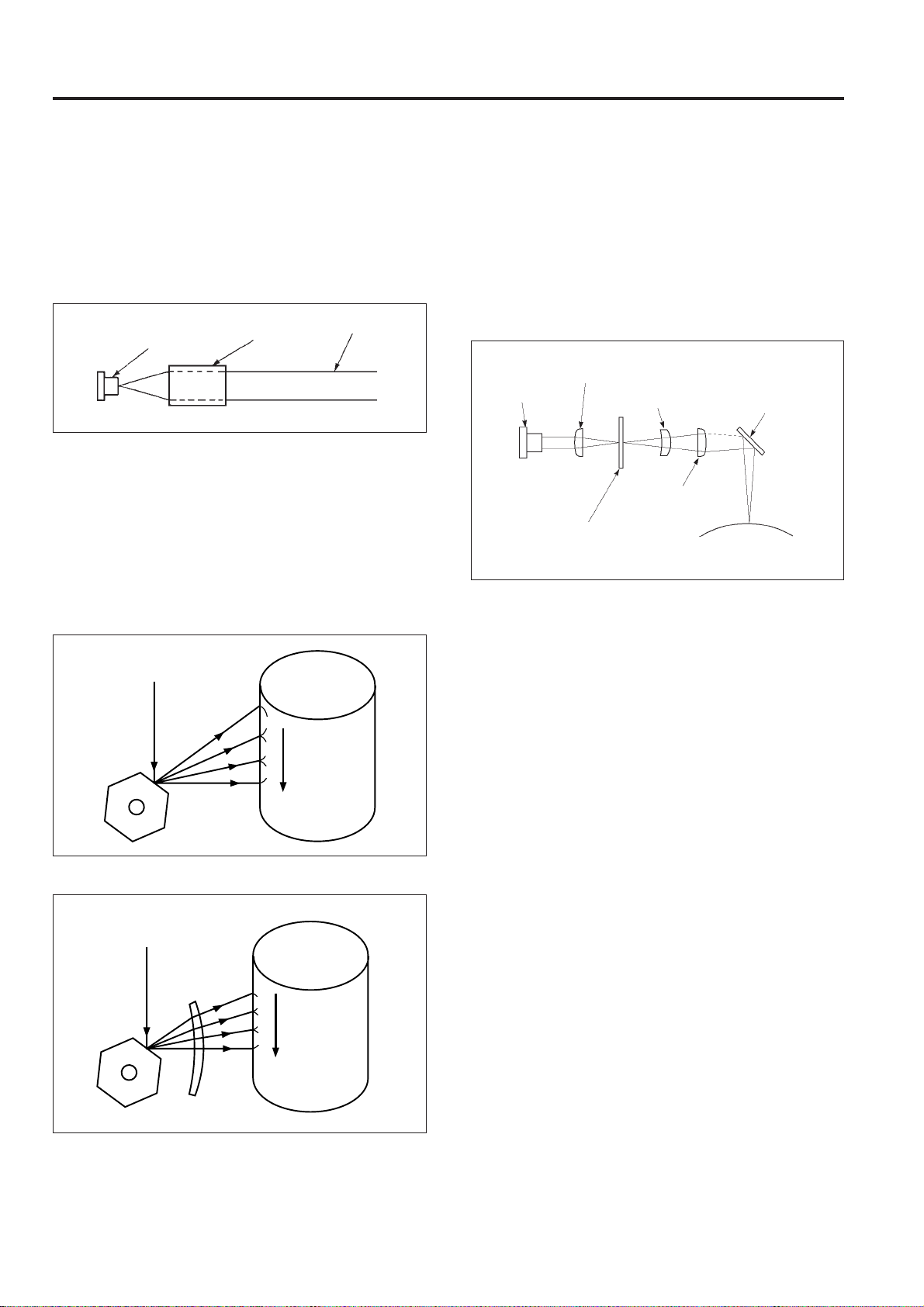
[2] Structure and function of the write unit
The internal structure of the write unit and the laser beam
path are shown in the drawing below.
Reflecting
Index
sensor
Laser
diode
Collimator lens
Index lens
Cylindrical
lens 1
mirror
Index mirror
Cylindrical
lens 2
fø lens
Laser Beam Path
Semiconductor laser (LD) Collimator lens
Polygon mirrorCylindrical lens 1 (Cy1)
fø lens
Reflecting mirror
Index mirror
Cylindrical lens 2 (Cy2)
OPC drum
3 - 1
Index lens Index sensor
OUTLINE of SYSTEM FUNCTION
The lenses and mirrors in the laser beam path have the
following functions.
1. Collimator lens
The collimator lens operation is shown in the figure. This
lens receives a light beam from a source having a widening
angle as shown and beams it outward in parallel rays.
Semiconductor laser
Collimator
lens
Parallel
rays
2. Polygon mirror
This is a rotating mirror for converting laser light into
scanning light and is driven by M5 (polygon). This
equipment utilizes a 6-sided mirror.
3. fø lens
When an ordinary converging lens is used the laser beam
speed varies at the center and ends when scanning the drum
surface due to the fixed position of the polygon mirror as
shown in the figure.
Laser beam
4. Cylindrical lens
Two lenses, the cylindrical lens 1 (Cy1) and the cylindrical
lens 2 (Cy2) are used to eliminate the tilt error of the polygon
mirror.
If the cylindrical lenses 1 and 2 are placed around the
polygon mirror as shown in the figure, the laser light is
collected on the polygon mirror by the cylindrical lens 1. The
light reflecting from the polygon mirror is again collected
above the drum by the cylindrical lens 2.
Cylindrical lens 1
laser diode
(cy1)
Cylindrical lens 2
Polygon mirror
fø lens
Mirror
(cy2)
Drum
The polygon mirror and drum surface have a mutual
interaction versus the cylindrical lens 2 regarding image and
object points so that when there is a tilt in the polygon mirror,
the light path is corrected by the cylindrical lens 2 and
scanning of the correct position performed.
a
Polygon
mirror
a > b > c
b
c
Speed of
scanning
slows
towards the
center.
Drum
An fø lens is utilized to obtain a fixed scanning speed.
Laser beam
a = b = c
a
Polygon
mirror
fø lens
b
c
Uniform
scanning
speed
Drum
5. Index sensor
The index sensor outputs an index signal (pulse) indicating
the degree that the light beam enters the index lens. This
index signal is used for the timing of the lead write position
each time an axial scan is made.
3 - 2
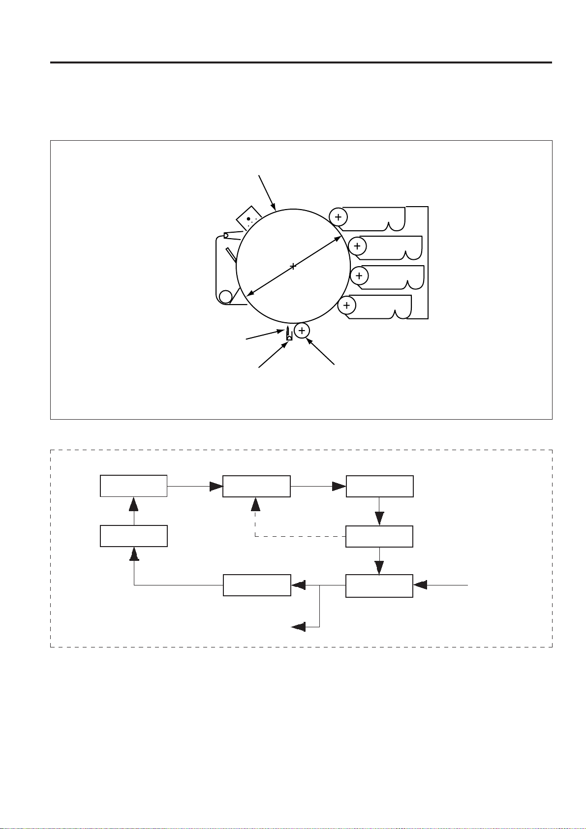
3.1.2 Forming the image
[1] Image forming process
OUTLINE of SYSTEM FUNCTION
Light exposure
(laser beam)
Charge
PCL
Cleaning
Separation
needle
Discharging
lamp
The image forming process is performed in the following
sequence.
ø 120 mm
Developing
Y
M
C
Bk
Transfer
PCL CHARGE EXPOSURE
CLEANING
DRUM CHARGE
REMOVAL
(fixing)
DEVELOPING
TRANSFER,
SEPARATION
(paper)
In full color printing, the CHARGE, EXPOSURE, DEVELOPING process is repeated in the order Y, M, C. TRANSFER is
performed after the CHARGE of Bk, EXPOSURE and DEVELOPING.
3 - 3
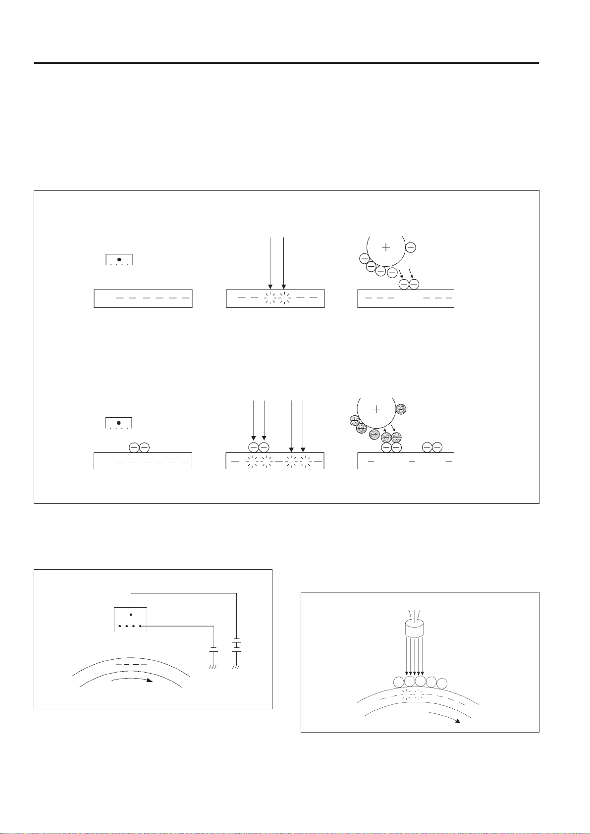
OUTLINE of SYSTEM FUNCTION
[2]Process description
This machine being a color printer is provided with a 4 color
developer (Y,M,C,Bk).
The KNC developing method is used and a full color image
is formed by overlapping the 4 toner colors on the drum.
(1st color charge)
Charge electrode
(2nd color charge)
(1st color exposure)
(2nd color exposure) (2nd color develop)
KNC (MB "K" New Color) Developing Method
⊇
ℑ
In this method the electrical charge on the light sensitive
ℑ
portion is eliminated and toner made to adhere to that
ℑ
portion. (reverse developing).
ℑ
This process is repeated until several toner colors have
ℑ
been formed on the light sensitive portion.
⊄
(1st color develop)
Developing sleeve
Toner
DrumDrum Drum
↓
Charge electrode
Drum Drum
Drum
1. Charge
The charge is applied with the Scolotron method.
A fixed voltage is applied to the wire grid and a uniform
charge applied to the drum.
Charge electrode
2. Exposure
Exposure with the laser beam from the write unit removes the
electrical charge on the drum.
The second and following exposures with the laser beam
eliminate the charges on the drum by laser light on the toner
layer even when toner is already adhering to it.
3 - 4

3. Developing
Toner with a negative charge is made to adhere to the
portions where the charge has been eliminated by light
exposure. The second and following developing operations
work by means of a static charge between the drum and
developing toner even at developing points where the toner
already adheres.
The developing bias is a DC bias voltage overlapped with an
AC bias voltage.
Drum
OUTLINE of SYSTEM FUNCTION
Drum
Separation
needle
Toner
Paper
6. Discharging
In order to improve separator performance, charge decline of
the drum is performed by applying light from a charge
removal lamp.
4. Transfer
In this process the toner is transferred to the paper by
applying a positive bias charge to the transfer roller.
Drum
Toner
Transfer roller
Paper
5. Separator
In order to prevent the paper from winding around the drum
after the transfer process, a charge removal brush eliminates
the charge remaining from AC voltage overlapped with an
DC bias voltage, from the paper and from the toner that was
transferred to the paper.
Drum
Discharging lamp
Paper
6. Transfer roller cleaning
In order to clean off the toner adhering to the transfer roller
after the print sequence is complete, a bias voltage of reverse
polarity is applied per each rotation of the transfer roller and
the toner on the transfer roller is made suctioned to the drum
side.
Drum
3 - 5

OUTLINE of SYSTEM FUNCTION
8. Cleaning
The remaining toner on the drum is removed by the cleaning
blade. The cleaning blade in this machine function by
compression release operation. This compression state is
only used after the last developing (Black) during multicolor
mode.
Cleaning blade
9. PCL (Pre Charge Lamp)
Before charging, the PCL uses light to remove the remaining
charge on the drum.
PCL
Drum
3 - 6

3.1.3 Fixing
[1] Overview
OUTLINE of SYSTEM FUNCTION
5. Fixing temperature
Set temperature: 180 °C
Fixing roller - upper
Fixing cleaning roller
Fixing oil roller
Fixing
Heater
lamp
Fixing roller - lower
The toner transferred to the paper is made to adhere to the
paper by means of heat and pressure.
1. Fixing roller - upper
This roller has a rubber coating over a metal surface and a
PFA tube sheath over the surface. This roller is driven by a
motor in the main drive unit.
The center of the roller is warmed by a heating lamp and this
temperature varies according to the type of paper that the
toner must adhere to.
2. Fixing roller - lower
This roller has a rubber coating over a metal surface and a
PFA tube sheath over the surface. A compression spring
provides a 1.72 kg/cm force to press contact on the upper
fixing roller.
3. Fixing oil roller
The roller contains a certain quantity of oil which is supplied
in minute amounts to the upper fixing roller. This improves
separation and prevents OHT permeability and the paper
winding around the upper fixing roller.
4. Fixing cleaning roller
This roller cleans off toner which adheres to the fixing oil
roller by cleaning the surface of the fixing oil roller.
3 - 7

OUTLINE of SYSTEM FUNCTION
3.2 MECHANICAL SECTION
3.2.1 Center cross sectional view/Laser beam path
[1] Center cross sectional view
PCL
Write unit
Drum cartridge
Fixing unit
Transfer unit
Charge electrode unit
Toner supply unit
Toner bottle
Y Developing unit
M Developing unit
Color Developing unit
C Developing unit
Bk Developing unit
Multi feed tray
Paper feed tray
[2] Laser beam path
Index mirror
Separation
needle
Cylindrical
lens 1
Discharging
lamp
Laser
diode
Paper feed unit
Transfer
roller
Index
sensor
Index lens
fø lensPolygon mirror Cylindrical lens 2
3 - 8
Mirror
3.2.2 Electronic parts layout
10
[1] Circuit boards layout, display layout
OUTLINE of SYSTEM FUNCTION
17
23
6
20
21
3
1
7
15
12
11
5
16
14
19
18
8
9
4
2
1 ENGCB Engine controller PCB
2 LDB LD drive PCB
3 PSIZEB Paper size sensor PCB
4 INDXSB INDEX sensor PCB
5 MRLB Main unit relay PCB
6 DVRLB1 Developing relay PCB1
7 DVRLB2 Developing relay PCB2
8 DVRLB3 Developing relay PCB3
9 DVRLB4 Developing relay PCB4
10 DVRLB5 Developing relay PCB5
11 GMDB Density sensor PCB
12 PCLB PCL PCB
22
13
13 OSLB Discharging lamp PCB
14 DRLB Drum unit relay PCB
15 HV High voltage power source
16 DCPS DC power source
17 OB Operation PCB
18 HUMB Humidity sensor PCB
19 PFB Paper feed PCB
20 DMCB Motor control PCB
21 PRNCB Printer controller PCB
22 PMDB Polygon drive PCB
23 LCD Operation panel LCD display
3 - 9

OUTLINE of SYSTEM FUNCTION
[2] Motor - solenoid - heater layout
8
6
4
2
7
3
5
9
1
10
1 M1 Main motor
2 M2 Paper feed motor
3 M3 Developing motor
4 M4 Control motor
5 M5 Polygon motor
6 M6 Main unit cooling fan
7 SD1 Developing control SD
8 SD2 Toner supply SD
9 SD3 Paper feed SD
10 L1 Fixing heater lamp
3 - 10

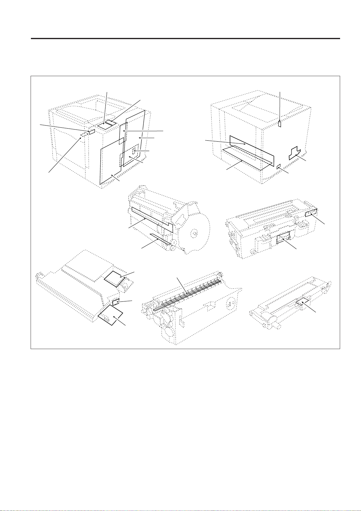
[3] Switch, sensor layout
13
12
14
OUTLINE of SYSTEM FUNCTION
4
1
3
10
2
7
5
11
17
8
6
9
16
1 SW1 Main switch
2 MS1 Interlock switch
3 PS1 Cam position PS
4 PS2 Toner supply PS
5 PS3 Main wire cleaner home position PS
6 PS4 Registration PS
7 PS5 Waste toner full detection PS
8 PS6 Paper detect PS
9 PS7 Multi feed paper detect PS
15
10 PS8 Paper eject PS
11 INDXS Index sensor
12 YTDS Toner density sensor (Y)
13 MTDS Toner density sensor (M)
14 CTDS Toner density sensor (C)
15 BKTDS Toner density sensor (K)
16 TH1 Fixing temperature sensor
17 TS1 Fixing thermostat
3 - 11
OUTLINE of SYSTEM FUNCTION
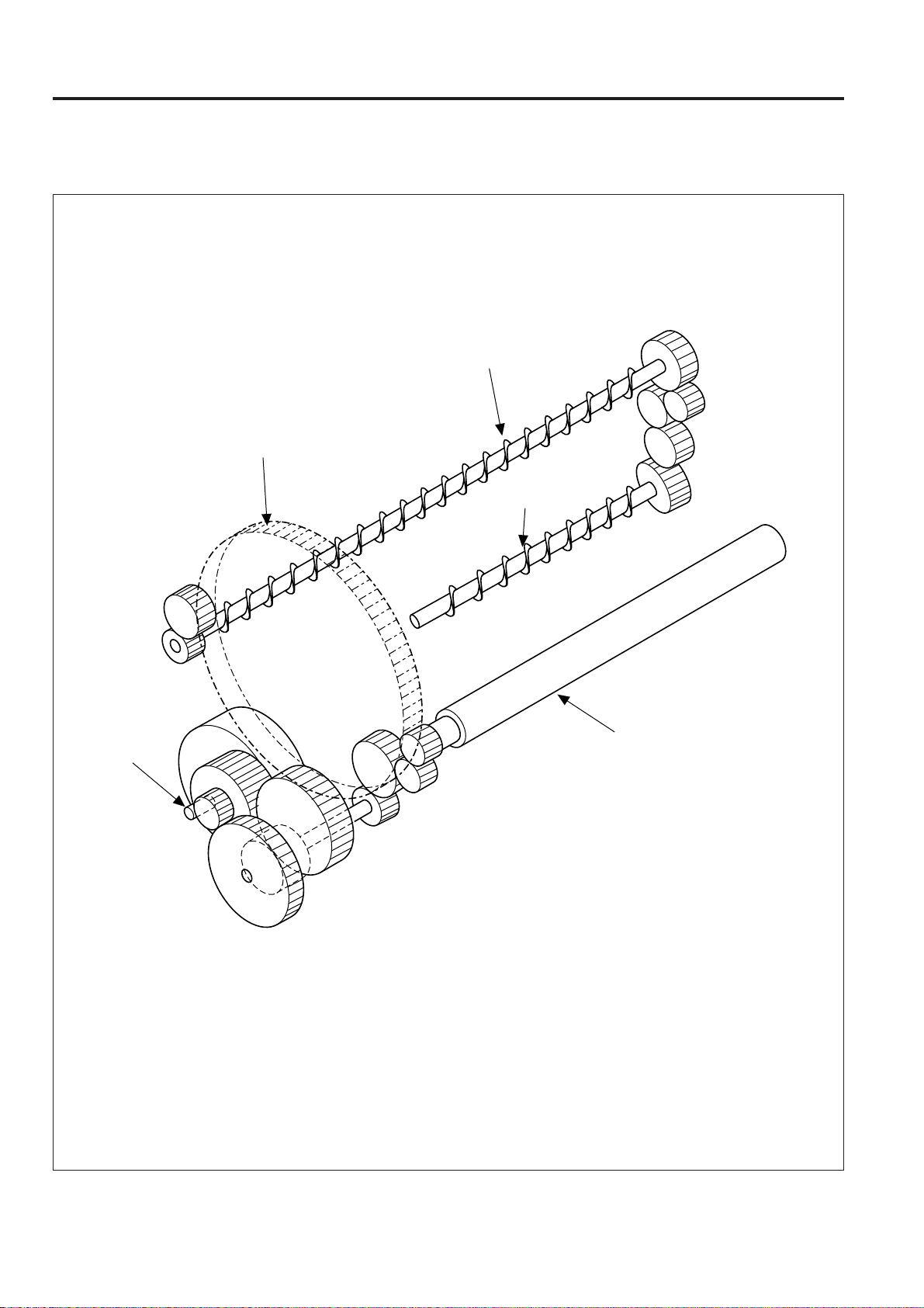
3.2.3 Drive system diagram
[1] Main motor drive section 1
Drum gear
Toner collection screw
(Drum cartridge)
Toner
collection screw
(Transfer unit)
M1
Transfer roller
3 - 12
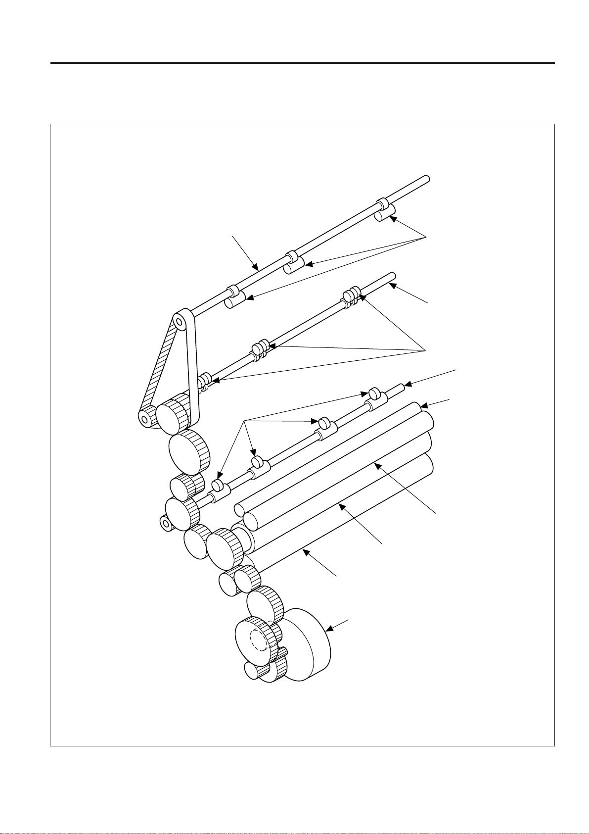
[2] Main motor drive section 2
OUTLINE of SYSTEM FUNCTION
Drive shaft (Upper)
Fixing paper exit
roller (Upper)
Driven roller (A)
Drive shaft (Lower)
Driven roller (B)
Fixing paper exit
roller (Lower)
Fixing cleaner roller
3 - 13
Oil roller
Fixing roller (Upper)
Fixing roller (Lower)
M1

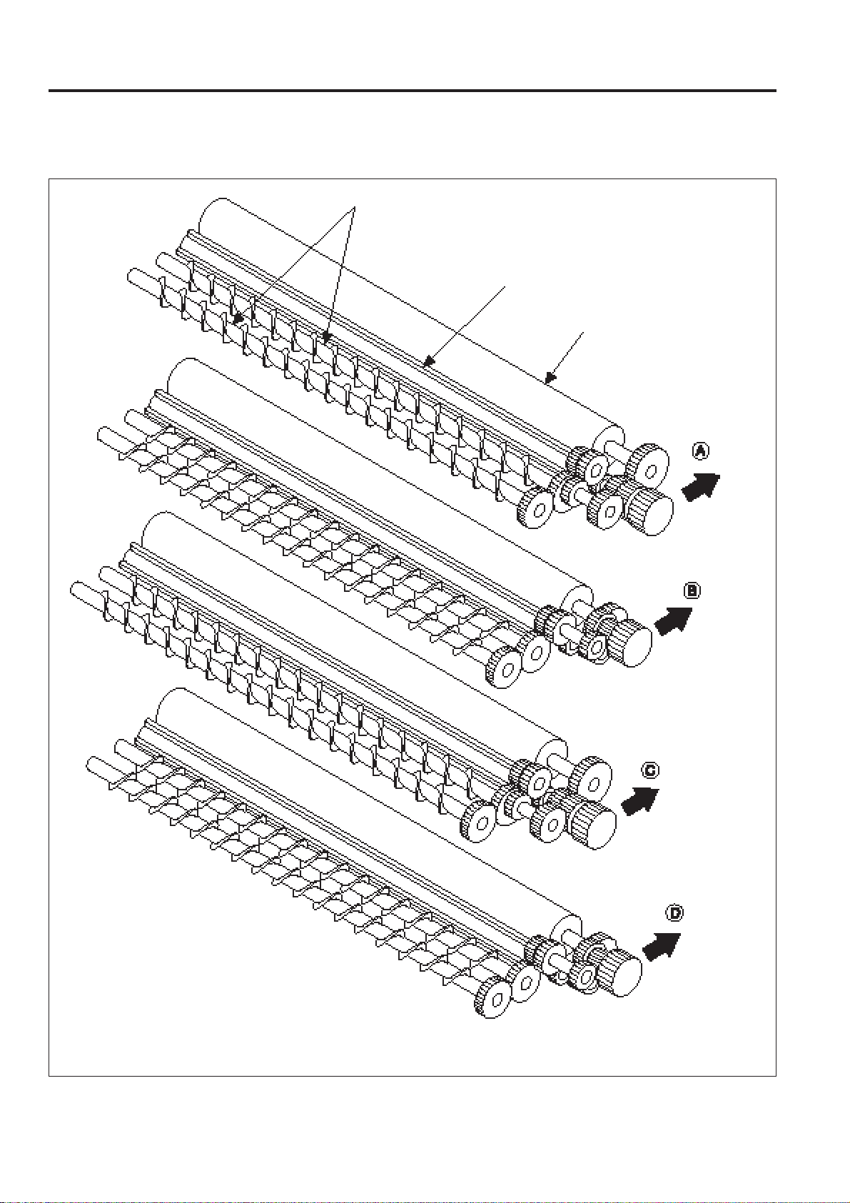
OUTLINE of SYSTEM FUNCTION
[3] Paper feed section
Paper feed conveyance roller
Paper feed driven roller
Paper feed pickup roller
Multi feed pickup roller
Paper feed
conveyance roller
Paper feed
planetary gear
Paper feed
planetary arm
Paper feed delivery stopper (A)
SD3
Paper feed delivery stopper (B)
M2
3 - 14

[4] Developing drive section 1
OUTLINE of SYSTEM FUNCTION
M3
Planetary gear
Developing drive
planetary arm (Upper)
Sun gear
SD1
Developing drive
planetary arm (Lower)
Sun gear
3 - 15
OUTLINE of SYSTEM FUNCTION
[5] Developing drive section 2
Developing Unit (Y)
Developing Unit (M)
Developing Unit (C)
Agitator screw
Developing liquid wheel
Developing sleeve
Developing Unit (Bk)
3 - 16

[6] Toner supply section
Planetary gear
OUTLINE of SYSTEM FUNCTION
Toner supply arm
Toner supply planetary arm
SD2
M3
Encoder plate
Toner supply screw (C)
Toner supply screw (M)
Sun gear
Toner supply arm holder case
Toner supply
screw (Bk)
Toner supply
control arm
Toner supply screw (Y)
Toner supply
control planetary arm
3 - 17
OUTLINE of SYSTEM FUNCTION
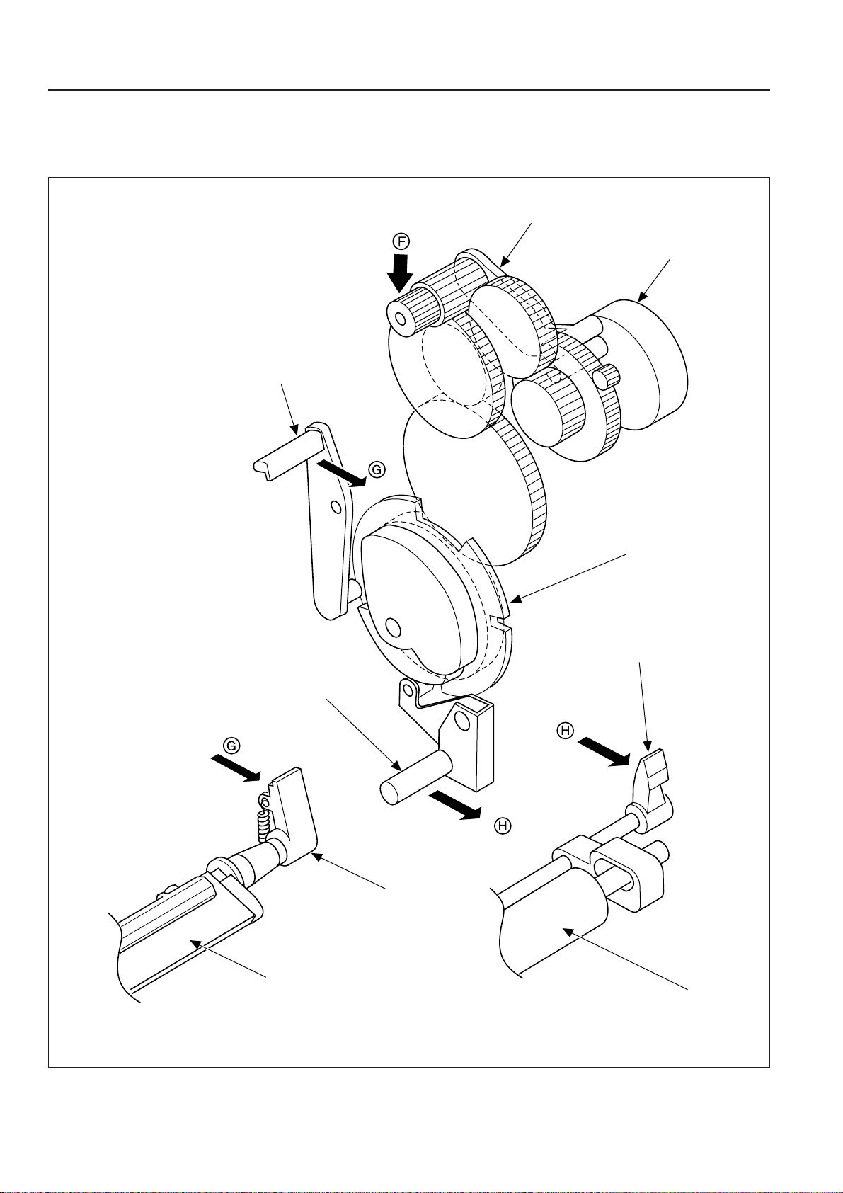
[7] Cleaning blend/transfer roller Drive section
Blade release arm
Control planetary arm
M4
Transfer roller
release arm
Cam gear
Transfer roller release lever
Blade release lever
Cleaning blade
Transfer roller
3 - 18

3.3 OPERATION AND CONTROL
3.3.1 Write section
[1] Write unit structure
OUTLINE of SYSTEM FUNCTION
Index lens
Index sensor PCB
LD drive PCB
Laser diode
Collimator lens
Cylindrical lens 1
Heat sink
(Bottom side)
Polygon drive PCB
Reflecting mirror
The write unit is comprised of an LD drive PCB, index
sensor PCB, polygon drive PCB, and various lenses and
mirrors for the laser beam path.
Refer to " 3.1.1 Image writing" for details on the internal
laser beam path.
A laser light shield plate that opens and closes by means of
a spring is installed to ensure safety. When the front door
on the main unit is opened, an actuator triggers the light
shield plate to block the laser beam output window.
Cylindrical lens 2
Laser light shield plate
Index mirror
fø lens
Polygon mirror
with air bearing
M5
[2] Write section operation
The image data from the PRNCB (printer controller) is
converted in the ENGCB (engine controller) into a pulse
signal (LD-PWM) with a pulse width corresponding to the
LD (laser diode) emissions per each image dot. This pulse
signal is sent to the LDB (LD drive).
The LDB regulates the laser output by means of the
control signal from the ENGCB.
The M5 (polygon) of write unit rotates the polygon mirror
to axially scan the drum with the laser beam from the LD.
Note: Take care not to bend or damage the heat sink
on the back of the unit when placing the write unit
that was removed in a convenient location.
3 - 19
Since is damaged with dirt and dust it used the
air bearing, never open the write unit lid.
 Loading...