

Kongsberg HiPAP 502, HiPAP 352, HiPAP 452, HiPAP 102 Instruction Manual

Instruction Manual
HiPAP
High Precision Acoustic Positioning
502/452/352/102 systems


502/452/352/102System
HiPAP
InstructionManual
396013/D
January2019©KongsbergMaritimeAS

Documentinformation
•Product:KongsbergHiPAP
•Document:InstructionManual
•Documentnumber:396013
•Revision:D
•Dateofissue:18January2019
Copyright
TheinformationcontainedinthisdocumentremainsthesolepropertyofKongsberg
MaritimeAS.Nopartofthisdocumentmaybecopiedorreproducedinanyformorby
anymeans,andtheinformationcontainedwithinitisnottobecommunicatedtoathird
party,withoutthepriorwrittenconsentofKongsbergMaritimeAS.
Warning
Theequipmenttowhichthismanualappliesmustonlybeusedforthepurposefor
whichitwasdesigned.Improperuseormaintenancemaycausedamagetothe
equipmentand/orinjurytopersonnel.Youmustbefamiliarwiththecontentsofthe
appropriatemanualsbeforeattemptingtooperateorworkontheequipment.
KongsbergMaritimedisclaimsanyresponsibilityfordamageorinjurycausedby
improperinstallation,useormaintenanceoftheequipment.
Disclaimer
KongsbergMaritimeASendeavourstoensurethatallinformationinthisdocumentis
correctandfairlystated,butdoesnotacceptliabilityforanyerrorsoromissions.
Supportinformation
Ifyourequiremaintenanceorrepair,contactyourlocaldealer.Y oucanalsocontactus
usingthefollowingaddress:km.support.hpr@kongsberg.com.Ifyouneedinformation
aboutourotherproducts,visithttp://www.kongsberg.com.Onthiswebsiteyouwillalso
ndalistofourdealersanddistributors.
KongsbergMaritimeAS
www.kongsberg.com

InstructionManual
Tableofcontents
ABOUTTHISMANUAL..............................................................5
HIPAP.....................................................................................6
Systemdescription.............................................................................................................7
Systemdiagram..................................................................................................................8
Systemunits.......................................................................................................................8
Transceiver...............................................................................................................9
1PPSConverter(Optional).......................................................................................9
ResponderDriverUnit(optional).............................................................................9
APOS-theHiPAPoperatorsystem.......................................................................10
Scopeofsupply................................................................................................................10
Generalsupplyconditions................................................................................................10
Receipt,unpackingandstorage..............................................................................11
Equipmentresponsibility........................................................................................11
Supportinformation.........................................................................................................12
INSTALLINGTHEHIPAPHARDWAREUNITS..........................13
InstallingthecomputerwithaKM1000kit.....................................................................14
Installingthecomputerina19"rack...............................................................................15
Installingthetransceiver..................................................................................................15
Installingthe1PPSConverter..........................................................................................16
InstallingtheResponderDriverUnit...............................................................................16
CABLELAYOUTANDINTERCONNECTIONS.............................18
Topsidecableplan............................................................................................................19
Sonarroomcableplan(transceiver)................................................................................20
Listofcables....................................................................................................................21
InstallingtheHiPAPcables..............................................................................................23
InstallingtheHiPAPtopsidecables.......................................................................23
InstallingtheHiPAPsonarroomcables.................................................................24
Connectingpowerandgroundtothetransceiver...................................................24
Connectingthetransducertothetransceiver.........................................................27
ConnectingtheResponderDriverUnittothetransceiver.....................................28
Connectingthetransceivers....................................................................................30
OPERATINGPROCEDURES.....................................................31
MAINTENANCE......................................................................32
AboutElectrostaticDischarge(ESD)..............................................................................33
Maintenancephilosophy..................................................................................................34
Preventivemaintenanceschedule....................................................................................35
396013/D
3

HiPAP
Creatingabackup............................................................................................................35
Transceiverunit................................................................................................................36
ReplacingtheEthernetswitch................................................................................36
RemovingtheLPT32Transceiverboard...............................................................36
Removingalterboard..........................................................................................37
Removingthepowermodulefromthetransceiverunit.........................................38
Replacingthepowermoduleinthetransceiverunit..............................................39
Replacingthefanunitinthetransceiverunit.........................................................39
Replacingtheterminalblockinthetransceiverunit..............................................39
Replacingafuseinthetransceiverunit..................................................................40
DRAWINGFILE......................................................................41
TECHNICALSPECIFICATIONS................................................52
Interfacespecications.....................................................................................................53
Weightsandoutlinedimensions......................................................................................53
Computerweightandoutlinedimensions..............................................................53
Transceiverweightandoutlinedimensions...........................................................54
ResponderDriverUnitweightandoutlinedimensions.........................................54
Powerrequirements.........................................................................................................54
Computerpowerrequirements...............................................................................54
Transceiverpowerspecications............................................................................55
ResponderDriverUnitpowerspecications..........................................................55
Environmentalrequirements............................................................................................55
Computerenvironmentalrequirements..................................................................55
Transceiverenvironmentalrequirements...............................................................56
ResponderDriverUnitenvironmentalrequirements.............................................56
EQUIPMENTHANDLING.........................................................57
Inspectionofunitsandtransportationboxesafterarrival................................................58
Unpackingstandardpartsandunits.................................................................................58
Specicationsforstorageafterunpacking.......................................................................60
TransportingKongsbergMaritimeequipment.................................................................61
4
396013/D

Aboutthismanual
Aboutthismanual
Thepurposeofthismanualistoprovidethedescriptions,proceduresanddetailed
parameterexplanationsrequiredtoallowforsafeandefcientuseoftheHiPAP.
Targetaudience
ThismanualisintendedforallusersoftheHiPAP.
Onlineinformation
Allend-usermanualsprovidedforoperationandinstallationofyourHiPAPcanbe
downloadedfromourwebsite.
•https://www.km.kongsberg.com
Registeredtrademarks
Observetheregisteredtrademarksthatapply.
Windows
othercountries.
HiPAP
countries.
cNODE
countries.
®
isaregisteredtrademarkofMicrosoftCorporationintheUnitedStatesand
®
isaregisteredtrademarkofKongsbergMaritimeASinNorwayandother
®
isaregisteredtrademarkofKongsbergMaritimeASinNorwayandother
396013/D
5

HiPAPInstructionManual
Topics
Systemdescription,page7
Systemdiagram,page8
HiPAP
Systemunits,page8
Scopeofsupply,page10
Generalsupplyconditions,page10
Supportinformation,page12
6
396013/D

Systemdescription
TheHiPAPsystemisdesignedforoptimalpositioningofsubseaobjectsinbothshallow
anddeepwater.
TheHiP APsystemsprovidesaccuratepositionsofsubseaobjectssuchasRemotely
operatedvehicles(ROVs),Autonomousunderwatervehicles(AUV’s),towedbodiesor
xedseabedtransponders.
ThesystemisofferingtheuserawiderangeoftransponderchannelsandcNODE
transpondermodelsfordepthsratingdownto11000metres.
TheHiPAPsystemsuseasignalprocessingtechniquewhichenablesnarrowtransmitter
andreceiverbeamstobegeneratedinalldirectionswithinthelowerhalfofthe
transducer,usingelectronicbeamcontroltoachieveaccuracy.
HiPAP
396013/D
7
HiPAPInstructionManual
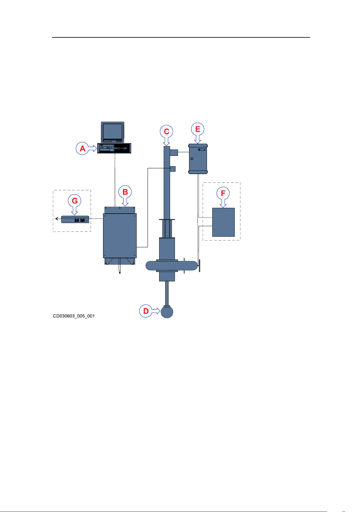
Systemdiagram
ThesystemdiagramidentiesthemaincomponentsofabasicHiP APsystem.Only
themainconnectionsbetweentheunitsareshown.Detailedinterfacecapabilitiesand
powercablesarenotshown..
AComputer
BTransceiver
CHullunit
DTransducer
EHoistcontrolunit
FGatevalvecontrolunit(optional)
GResponderDriverUnit(optional)
Systemunits
8
396013/D
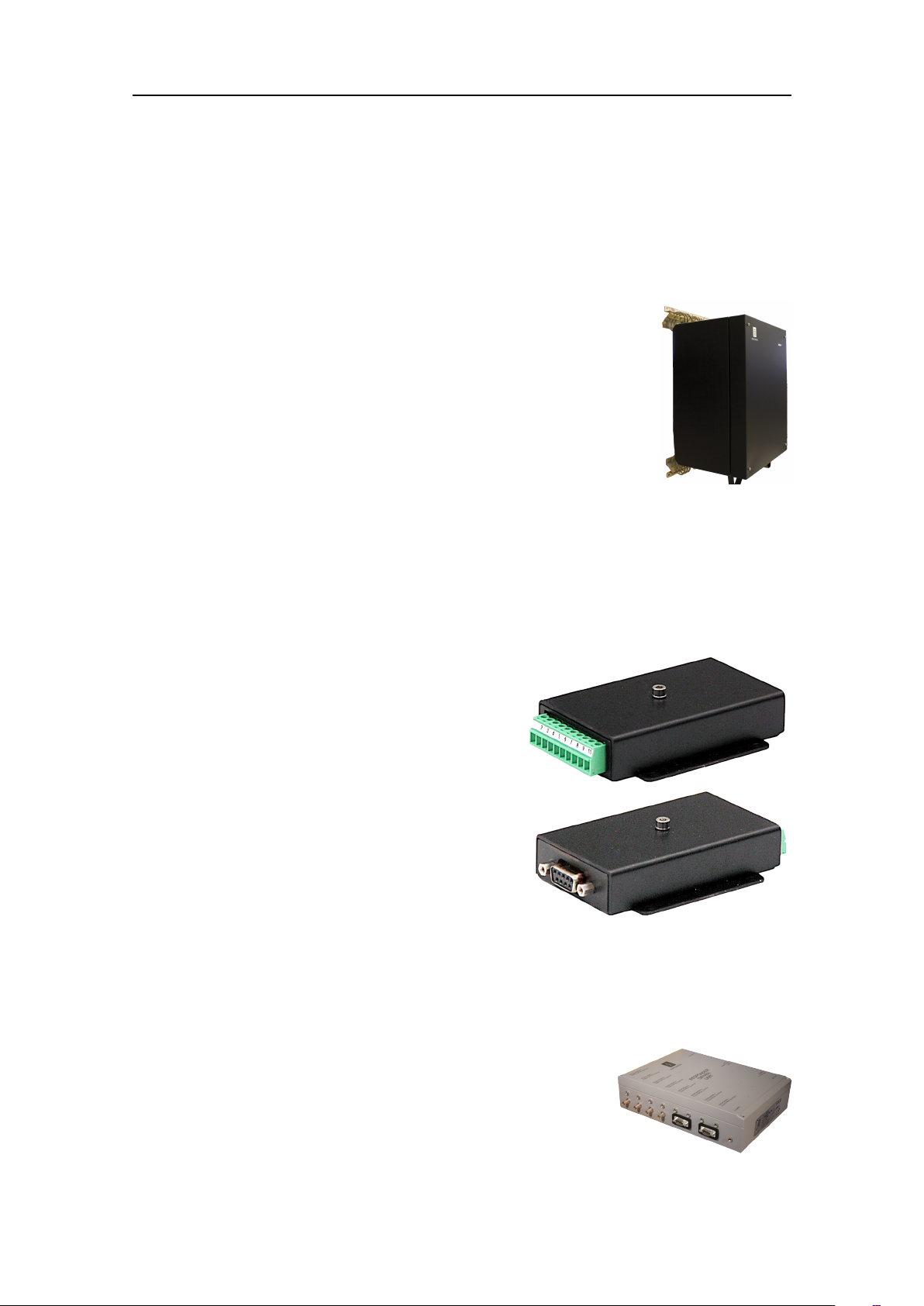
Transceiver
Thetransceiverisprovidedtotransmitacousticenergythroughwater.Thistransmission
andreceptionarecommonlyreferredtoasaping.Aftereachtransmission,the
transceiverreceivestheechoesfromthetargetsinthewaterand/ortheseabed.These
echoesarelteredandamplied,andthenconvertedtodigitalformat.
Thetransceiverisastainlesssteelcabinetthatcontainsracks
holdingthesystemelectronicmodules.Itcontainsanumberof
circuitboardsandmodules.Thetransceiverisdesignedtobe
installedonasuitablebulkheadandarettedwithvibration/shock
absorberstoreducetheeffectsofvesselvibrations.
HiPAP
1PPSConverter(Optional)
The1PPSConverterisaspecialmademoduledesignedforinterfacingGPSsignalsto
theHighPrecisionAcousticPositioningOperatorstationandtothe502/452/352/102
System.
TheGPSsignalconsistsofRS-232serialNMEA
data,anda1PPSTTLpulsetosynchronisethe
internaltimingclockonHighPrecisionAcoustic
Positioningoperatorstationand502/452/352/102
SystemControlprocessortotheGPSclock.
TheRS-232serialNMEAdataistransferred
straightthroughthemodule,whilethe1PPSTTL
pulseisshapedtoaxedpulselength.
ResponderDriverUnit(optional)
TheResponderDriverUnitprovidesrespondertriggersignalstoresponders.
TheResponderDriverUnitisastand-aloneunit.The
ResponderDriverUnitisconnectedtotheinterfaceunitand
theswitch.APOScontrolswhichdriveisbeingactivewhile
thesync/timingisreceivedfromthetransceiver.
396013/D
9

HiPAPInstructionManual
APOS-theHiPAPoperatorsystem
TheHiP APsystemisoperatedfromanacousticpositioningoperatorstation(APOS).The
operatorstationisaWindowsbasedcomputerrunningdedicatedacousticpositioning
software.
ThesystemcanbeoperatedfromonesingleAPOSstationorfromawidenumberof
APOSoperatorstationsconnectedonanetwork.
Scopeofsupply
ToassembleacompleteHiP APsystem,youwillneedasetofsystemunits.Themain
unitsrequiredareprovidedwiththestandarddelivery.Otherrequiredunitsmaybe
purchasedfromKongsbergMaritimeorobtainedlocally.Someunitsareoptional.
WhenyouunpackthepartsprovidedwiththeHiP APdelivery,makesurethatthe
followingitemsareincluded.
•Computer
•Transceiver
•Cables
Optionalitems
•ResponderDriverUnit
•1PPSConverter
Generalsupplyconditions
GeneralsupplyconditionsapplytothisHiPAPdelivery.
Relatedtopics
Inspectionofunitsandtransportationboxesafterarrival,page58
Unpackingstandardpartsandunits,page58
Specicationsforstorageafterunpacking,page60
TransportingKongsbergMaritimeequipment,page61
10
396013/D

Receipt,unpackingandstorage
Uponacceptingshipmentoftheequipment,theshipyardand/orthedealermustensure
thatthedeliveryiscompleteandinspecteachshippingcontainerforevidenceofphysical
damage.
Iftheinspectionrevealsanyindicationofcrushing,dropping,immersioninwateror
anyotherformofdamage,therecipientshouldrequestthatarepresentativefromthe
companyusedtotransporttheequipmentbepresentduringunpacking.
Allequipmentmustbeinspectedforphysicaldamage,i.e.brokencontrolsandindicators,
dents,scratchesetc.duringunpacking.Ifanydamagetotheequipmentisdiscovered,the
recipientmustnotifyboththetransportationcompanyandKongsbergMaritimesothat
KongsbergMaritimecanarrangeforreplacementorrepairofthedamagedequipment.
Onceunpacked,theequipmentmustbestoredinacontrolledenvironmentwithan
atmospherefreeofcorrosiveagents,excessivehumidityortemperatureextremes.
Theequipmentmustbecoveredtoprotectitfromdustandotherformsofcontamination
whenstored.
HiPAP
Equipmentresponsibility
Unlessotherwisestatedinthecontract,theshipyarddoingtheinstallationand/or
equipmentdealerbecomesfullyresponsiblefortheequipmentuponreceipt.
Thedurationofresponsibilitycover:
•Theperiodoftimetheequipmentisstoredlocallybeforeinstallation
•Theentireinstallationprocess
•Commissioning
•Theperiodoftimebetweencommissioningandthenalacceptanceoftheequipment
bytheenduserorowner
Unlessotherarrangementshavebeenmadeinthecontract,theKongsbergHiP AP
warrantyperiod(asspeciedinthecontract)beginswhentheacceptancedocuments
havebeensigned.
396013/D
11

HiPAPInstructionManual
Supportinformation
ShouldyouneedtechnicalsupportforyourHiPAPyoumustcontactaKongsberg
Maritimeofce.Alistofallourofcesisprovidedonourwebsite.Y oucanalsocontact
ourmainsupportofceinNorway.
•Companyname:KongsbergMaritimeAS
•Address:Strandpromenaden50,3190Horten,Norway
•Telephone:+4733034100
•Telephone24hsupport:+4733032407
•Telefax:+4733047619
•Website:http://www.km.kongsberg.com
•Supportwebsite:http://www.km.kongsberg.com/support_hpr
•E-mailaddress:km.support.hpr@kongsberg.com
12
396013/D

InstallingtheHiP APhardwareunits
InstallingtheHiPAP
hardwareunits
Topics
InstallingthecomputerwithaKM1000kit,page14
Installingthecomputerina19"rack,page15
Installingthetransceiver,page15
Installingthe1PPSConverter,page16
InstallingtheResponderDriverUnit,page16
396013/D
13
HiPAPInstructionManual
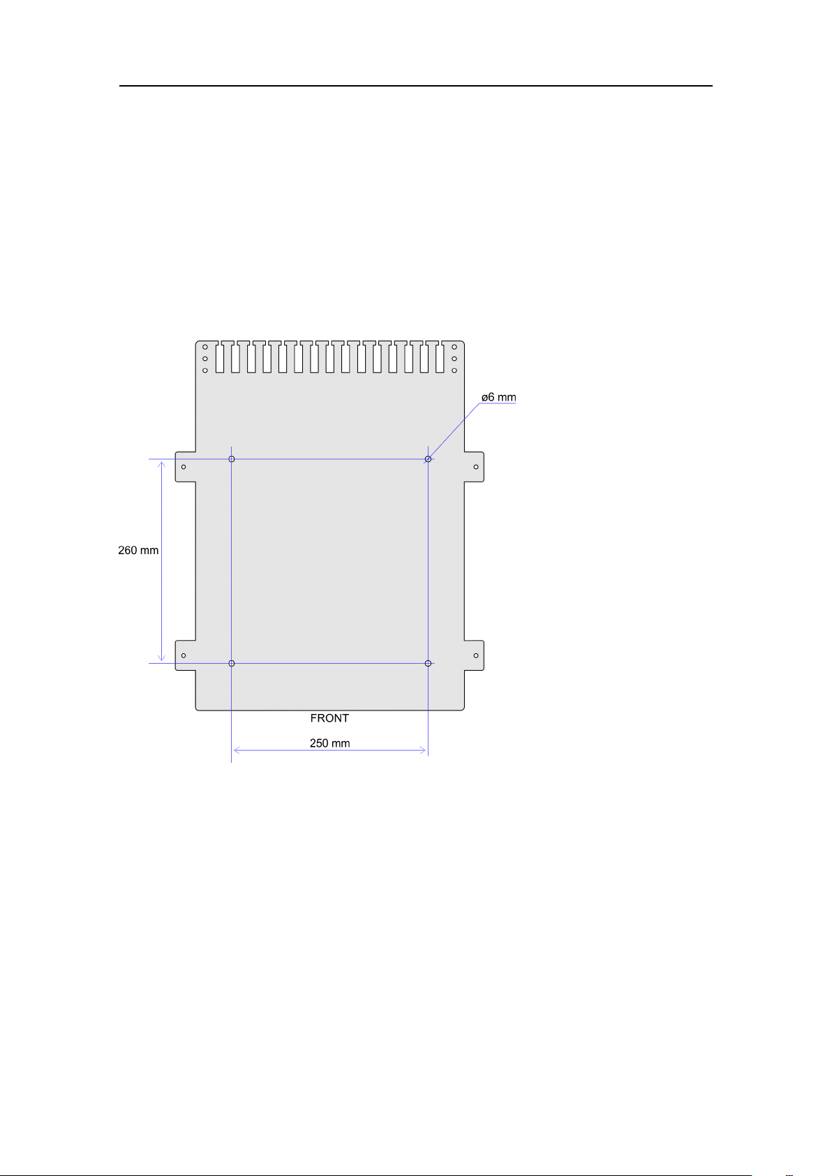
InstallingthecomputerwithaKM1000kit
Thecomputercanbeinstalledinsideaconsole,insideasuitablecabinet,ina19"rack
oronadesk.ThisproceduredescribeshowtoinstallthecomputerusingKM1000
kit(331385).
Prerequisites
InstallthecomputerhorizontalorverticalwiththeKM1000kit.
Procedure
1Preparefourholes,eachforM6,followingtheillustration.
2Mountthebottomplateusingcountersunkscrewsorbolts.
3Placethecomputeronthebottomplate.
4MountthetwobracketstothebottomplateusingM5lockingnutsandwashers.
Furtherrequirements
Connectthecables.
Afterelectricalinstallation,secureallcablestocablengersandholes.
14
396013/D
InstallingtheHiP APhardwareunits
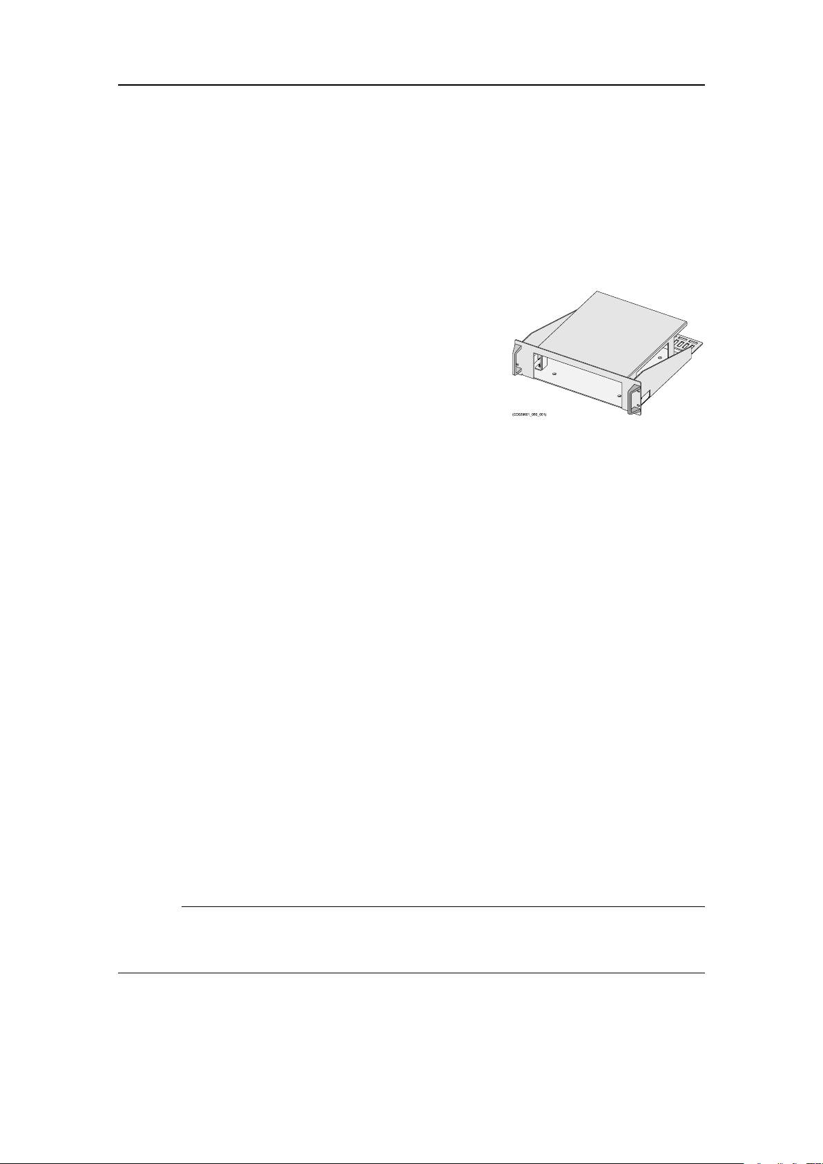
Installingthecomputerina19"rack
Thecomputercanbeinstalledinsideaconsole,insideasuitablecabinet,ina19"rackor
onadesk.Thisproceduredescribeshowtoinstallthecomputerusingrackkit371931.
Context
Procedure
1Removethelidfromtherackshelf.
2Placethecomputerontheshelfwiththefrontto
thefrontoftheshelf.
3Mountthelid,andsecureproperlywiththelock
nutsandwashers.
4Mounttheshelftotherackwiththecagenuts,
washersandscrewsprovided.
Furtherrequirements
Connectthecables.
Afterelectricalinstallation,secureallcablestocablengersandholes.
Installingthetransceiver
Thephysicallengthofthecableslimitthedistancebetweenthetransducerandthe
transceiver.
Prerequisites
Theremustbeaclearspaceofatleast500mminfrontoftheunitformaintenance
and200mmundertheunitforthecables.
Thetransceiverunitmustbemountedonabulkhead.Y oudonotneedtoremovethe
circuitboardsormodulesfromthetransceiverunitduringtheinstallationprocess.Keep
thetransceiverunitdooronduringtheinstallation.Makesurethattheunitisnotexposed
todust,moisture,vibrationorphysicaldamageduringtheinstallationprocess.
Thebracketsforhangingupthetransceiverisdeliveredwiththeunit.
Caution
Donotweldinthevicinityofthetransceiverunit.Firstweldthebrackets,thenbringin
thetransceiverunit.
Procedure
1Measureandmarkthelocationswheretomountthebrackets.
396013/D
15

HiPAPInstructionManual
Makesurethetransceiverisatasuitableheightforeasyaccess.
2Weldthebracketstothebulkhead.
3Cleantheweldsandbrackets,andpaintthemwithanappropriatepreservation
medium.
4Oncethepaintisdry,lifttheunitintopositionandaligntheunitontothebrackets.
5Startwiththeupperbracket,andbolttheshockabsorberstothebrackets.
Furtherrequirements
Connectthecables.
Relatedtopics
AboutElectrostaticDischarge(ESD),page33
Installingthe1PPSConverter
The1PPSconverterismountedonthecablebetweentheGPSreceiverandtheCOM
portusedonthecomputer.
Prerequisites
The1PPSconverterrequiresapowerof9-15VDCand100mA.
Weadviceyoutomountthe1PPSconvertercloserthan10mtotheGPSreceiver.
Procedure
1Mounttheboxwhereversuitable.
2Fastenthe4screwsoneithersideofthe1PPSconverter.
InstallingtheResponderDriverUnit
TheResponderDriverUnitprovidesrespondertriggersignalstoresponders.TheRDU
isastand-aloneunitandcanbemountedhorizontallyorvertically.
Prerequisites
Theunitshouldbelocatedwhereitismostsuitableforconnectingthecablestothe
responders.ThiscanbeclosetoRemoteOperatingVehicle(ROV)operationroom.
Theunitmustbeinstalledsoitiseasyaccessibleforoperatorstochecktheworking
conditionoftherespondertriggerstatusdiodes.
Procedure
1Opentheunitbyremovingthefourscrewsthatsecuresthelid.
16
396013/D

InstallingtheHiP APhardwareunits
2Liftoffthelidandseethefourmountingholes,oneineachcorner.
3Mounttheresponderdriverunitwheresuitable.
Themountingscrewswithnutsandwashersaredeliveredwiththeunit.
4Closetheunit.
396013/D
17

HiPAPInstructionManual
Topics
Cablelayoutand
interconnections
Topsidecableplan,page19
Sonarroomcableplan(transceiver),page20
Listofcables,page21
InstallingtheHiPAPcables,page23
18
396013/D
Cablelayoutandinterconnections
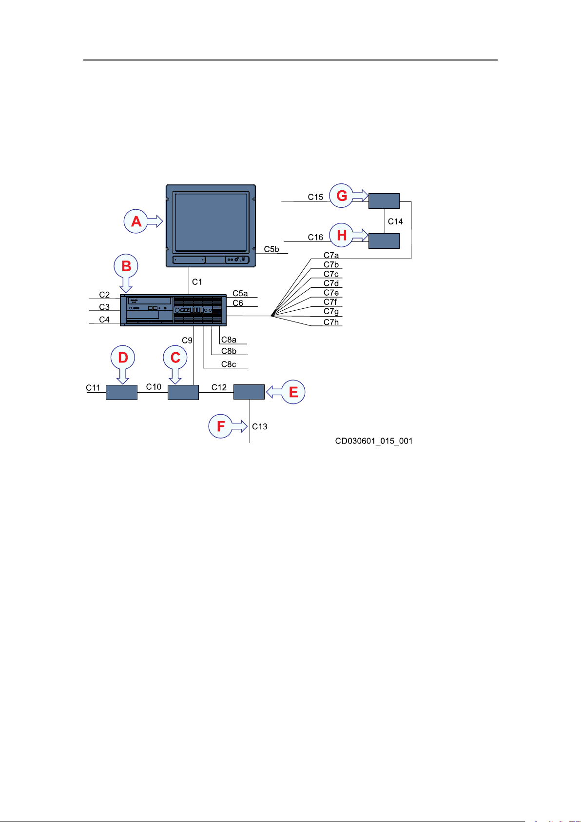
Topsidecableplan
Thetopside/bridgecablesincludethoseusedtoconnecttheHiPAPcomputerandthe
displaytoeachother,toACmainspower,andtoexternaldevices.
ADisplay
BComputer
CEthernetswitch
DPowersupply,Ethernetswitch
EPatchpanel
FFibreopticcablestothetransceiver
G1PPSConverter
HPowersupply,1PPSConverter
396013/D
19
 Loading...