


 Loading...
Instruction Manual
HiPAP®
High Precision Acoustic Positioning
Model 501/451/351/101
HiPAP®
High Precision Acoustic Positioning
Model 501/451/351/101
Instruction Manual

Document history
Rev |
Date |
Written by |
Checked by |
Approved by |
|
|
|
|
|
|
|
|
07.03.2013 |
AJ |
AD |
JEF |
|
H |
|
|
|
|
|
Replaced APC12 with MP8200 8 channel serial line model P/N: 364602. |
|||||
|
|||||
|
General updates. |
|
|
|
|
Copyright
© 2013 Kongsberg Maritime AS
All rights reserved. The information contained in this document remains the sole property of Kongsberg Maritime. No part of this document may be copied or reproduced in any form or by any means, and the information contained within it is not to be communicated to a third party, without the prior written consent of Kongsberg Maritime.
Disclaimer
Kongsberg Maritime endeavours to ensure that all information in this document is correct and fairly stated, but does not accept liability for any errors or omission.
Warning
The equipment to which this manual applies must only be used for the purpose for which it was designed. Improper use or maintenance may cause damage to the equipment and/or injury to personnel. The user must be familiar with the contents of the appropriate manuals before attempting to operate or work on the equipment. Kongsberg Maritime disclaims any responsibility for damage or injury caused by improper installation, use or maintenance of the equipment.
Support
All Kongsberg Maritime products:
Phone 24 hour: +47 33 03 24 07
E-mail: km.support@kongsberg.com
Kongsberg Maritime AS
Strandpromenaden 50 |
Telephone: +47 33 03 41 00 |
P.O.Box 111 |
Telefax: +47 33 04 47 53 |
N-3191 Horten, |
www.kongsberg.com |
Norway |
subsea@kongsberg.com |

Instruction Manual
Additional documents
Display manual
Separate manual supplied with the display. Not a Kongsberg Maritime document.
Keyboard manual
Separate manual supplied with the keyboard. Not a Kongsberg Maritime document.
Trackball
Separate document supplied with the trackball. Not a Kongsberg Maritime document.
Air to air heat exchange unit for Transceiver Unit x81
Not a Kongsberg Maritime document.
Air to air heat exchange unit for Transceiver Unit x21
Not a Kongsberg Maritime document.
Remarks
The reader
The installation information in this manual is intended for the design and installation engineers at the yard performing the installation. The information is supplied as the basis for the yard’s own installation drawings applicable to the vessel. On completion of the installation, this section may be used for reference purposes during system maintenance.
The maintenance information in this manual is intended to be used by a trained maintenance technician or engineer, with experience of electronic and digital circuitry, computers and electromechanical design. The level of information is based on
Kongsberg Maritime’s maintenance philosophy: The onboard technical personnel shall, with the help of the documentation and the system’s built-in test functions, be able to identify malfunctions, locate the fault, and replace major parts, modules and components on the “Line Replaceable Unit” (LRU) level. He/she will however not attempt to repair the LRUs.
303490/H |
I |

HiPAP® Model 501/451/351/101
High voltage safety warning
The following safety precautions must be followed at all times during installation and maintenance work:
Switch off all high-voltage power supplies.
Check the operation of any door interlocks and any other safety devices.
Completely discharge all high-voltage capacitors.
It should be noted that interlocks and safety devices are normally located only at regular access points, and high voltages may be exposed during dismantling.
____________________________________________________________
Caution |
Never work alone on high-voltage equipment! |
|
Refer to general safety procedures. |
____________________________________________________________
II |
303490/H |

|
Instruction Manual |
|
|
Table of contents |
|
1 |
ABOUT THIS MANUAL ........................................................................................ |
1 |
References ......................................................................................................................... |
1 |
|
Abbreviations .................................................................................................................... |
2 |
|
Backup ............................................................................................................................... |
2 |
|
Software upgrade............................................................................................................... |
2 |
|
2 |
SYSTEM DESCRIPTION....................................................................................... |
3 |
HiPAP® systems - short overview .................................................................................... |
4 |
|
HiPAP® system configuration .......................................................................................... |
4 |
|
|
HiPAP® system with Transceiver unit Model x81................................................... |
5 |
|
HiPAP® system with Transceiver unit Model x21................................................... |
6 |
|
HiPAP® redundant system ....................................................................................... |
7 |
|
Operator station ......................................................................................................... |
8 |
|
Transceiver unit (system-specific) ............................................................................ |
8 |
|
Hull unit (system-specific) ........................................................................................ |
9 |
APOS ................................................................................................................................. |
9 |
|
Sensors............................................................................................................................... |
9 |
|
Conversion kits for upgrading of an “old” HiPAP® system............................................. |
9 |
|
System units - short description ...................................................................................... |
10 |
|
|
Operator Station ...................................................................................................... |
10 |
|
Keyboard ................................................................................................................. |
11 |
|
Trackball.................................................................................................................. |
11 |
|
Display .................................................................................................................... |
11 |
|
1PPS converter (option) .......................................................................................... |
11 |
|
Ethernet switch/Converter....................................................................................... |
11 |
|
Fibre Splice Box...................................................................................................... |
12 |
|
Transceiver units ..................................................................................................... |
12 |
|
110 Vac to 230 Vac transformer - option for both transceiver units....................... |
15 |
3 |
TECHNICAL SPECIFICATIONS....................................................................... |
16 |
Operator Station............................................................................................................... |
17 |
|
Fibre Splice Box .............................................................................................................. |
17 |
|
Ethernet switch/Converter ............................................................................................... |
18 |
|
303490/H |
III |

HiPAP® Model 501/451/351/101
Transceiver units.............................................................................................................. |
18 |
Common data .......................................................................................................... |
18 |
Model x81 ............................................................................................................... |
19 |
Model x21 ............................................................................................................... |
20 |
110 Vac to 230 Vac transformer (option)........................................................................ |
20 |
SSBL accuracy ................................................................................................................ |
20 |
Transducer reference point...................................................................................... |
20 |
HiPAP® 501 ........................................................................................................... |
22 |
HiPAP® 451 ........................................................................................................... |
23 |
HiPAP® 351 ........................................................................................................... |
23 |
HiPAP® 101 ........................................................................................................... |
25 |
LBL accuracy .................................................................................................................. |
25 |
Range capabilities............................................................................................................ |
27 |
Fibre-optic cable .............................................................................................................. |
28 |
Patch cables ............................................................................................................. |
29 |
Connector type ST................................................................................................... |
30 |
4 INSTALLATION ................................................................................................... |
31 |
Supply conditions ............................................................................................................ |
33 |
Equipment responsibility......................................................................................... |
33 |
Installation guidelines ............................................................................................. |
33 |
Assistance from Kongsberg Maritime..................................................................... |
33 |
Before you start ............................................................................................................... |
34 |
Precautions and requirements.................................................................................. |
34 |
Standard tools .................................................................................................................. |
34 |
Special tools..................................................................................................................... |
35 |
Computer ......................................................................................................................... |
35 |
1PPS converter (option) .................................................................................................. |
37 |
Ethernet switch/Converter ............................................................................................... |
37 |
Fibre Splice Box .............................................................................................................. |
37 |
Transceiver units.............................................................................................................. |
38 |
Basic installation instructions ................................................................................. |
38 |
Vibrations ................................................................................................................ |
38 |
Important information about ventilation and maintenance ..................................... |
38 |
Transceiver unit Model x81 installation.................................................................. |
39 |
IV |
303490/H |

|
|
Instruction Manual |
|
Adapter Kit for x81 Transceiver ............................................................................. |
41 |
|
Transceiver unit Model x21 installation.................................................................. |
42 |
5 |
CABLES.................................................................................................................. |
46 |
Cable gland assembly procedure ..................................................................................... |
47 |
|
|
Securing and terminating the cables........................................................................ |
48 |
Basic cable requirements ................................................................................................. |
49 |
|
Cable planning................................................................................................................. |
52 |
|
Computer ......................................................................................................................... |
52 |
|
|
Computer connections............................................................................................. |
52 |
|
Computer Dual Net connection............................................................................... |
53 |
GPS input signals connections ........................................................................................ |
54 |
|
1PPS converter (option) .................................................................................................. |
54 |
|
Transceiver unit Model x81............................................................................................. |
57 |
|
|
Model x81 - transducer cable connection ............................................................... |
58 |
|
Transducer cable with plug ..................................................................................... |
59 |
Transceiver unit Model x21............................................................................................. |
61 |
|
|
Model x21 - transducer cable connection ............................................................... |
63 |
|
Transducer cable with plug ..................................................................................... |
63 |
Transducer to transceiver unit cables installation............................................................ |
64 |
|
|
Cable information.................................................................................................... |
64 |
|
HiPAP® 501/451 .................................................................................................... |
65 |
|
HiPAP® 351/101 (x81)........................................................................................... |
65 |
|
HiPAP® 351/101 (x21)........................................................................................... |
65 |
Fibre-optic cable installation ........................................................................................... |
66 |
|
6 |
OPERATION.......................................................................................................... |
69 |
HiPAP® operation........................................................................................................... |
69 |
|
7 |
MAINTENANCE ................................................................................................... |
70 |
Safety ............................................................................................................................... |
71 |
|
Before you start ............................................................................................................... |
72 |
|
Maintenance philosophy.................................................................................................. |
72 |
|
|
Verification.............................................................................................................. |
73 |
Maintenance schedule...................................................................................................... |
74 |
|
|
Maintenance chart ................................................................................................... |
74 |
Preventive maintenance ................................................................................................... |
74 |
|
303490/H |
V |

HiPAP® Model 501/451/351/101
8 CABLE PLAN AND INTERCONNECTIONS ................................................... |
75 |
9 SYSTEM UNITS - DETAILED DESCRIPTION ............................................... |
76 |
Computer ......................................................................................................................... |
76 |
Computer internal................................................................................................... |
77 |
How to open the computer ...................................................................................... |
78 |
Keyboard ................................................................................................................. |
78 |
Trackball.................................................................................................................. |
78 |
1PPS converter (option) .................................................................................................. |
78 |
Ethernet switch/Converter ............................................................................................... |
78 |
Replacement ............................................................................................................ |
78 |
Configuration .......................................................................................................... |
79 |
Fibre Splice Box .............................................................................................................. |
79 |
Transceiver unit Model x81............................................................................................. |
79 |
Model x81 internal layout ....................................................................................... |
80 |
Model x81 power sockets........................................................................................ |
81 |
Transceiver unit Model x81, PCB rack ................................................................... |
82 |
Replacement of Model x81 parts ............................................................................ |
82 |
Fuses........................................................................................................................ |
90 |
Transceiver unit Model x21............................................................................................. |
91 |
Model x21 internal layout ....................................................................................... |
91 |
Model x21 power socket ......................................................................................... |
93 |
Replacement of Model x21 parts ............................................................................ |
93 |
Circuit boards and units................................................................................................... |
97 |
Computer circuit boards and power unit ................................................................. |
97 |
Transceiver units ..................................................................................................... |
99 |
Transmit synchronization with external equipment .............................................. |
105 |
10 SPARE PARTS ................................................................................................. |
110 |
Operator station ............................................................................................................. |
110 |
Transceiver Model x81.................................................................................................. |
111 |
HiPAP® 501/451/351 system ............................................................................... |
111 |
HiPAP® 101 system ............................................................................................. |
112 |
Transducer cable with plug ................................................................................... |
112 |
Transceiver unit Model x21........................................................................................... |
113 |
VI |
303490/H |
|
Instruction Manual |
HiPAP® 351 system ............................................................................................. |
113 |
HiPAP® 101 system ............................................................................................. |
113 |
Transducer cable with plug ................................................................................... |
113 |
11 HIPAP® MODELS AND POSITIONING PRINCIPLES ........................... |
114 |
HiPAP® 501 ......................................................................................................... |
115 |
HiPAP® 451 ......................................................................................................... |
115 |
HiPAP® 351 ......................................................................................................... |
116 |
HiPAP® 101 ......................................................................................................... |
116 |
Positioning principles and processing ........................................................................... |
116 |
SSBL positioning .................................................................................................. |
117 |
LBL positioning .................................................................................................... |
118 |
Combined SSBL and LBL positioning ................................................................. |
122 |
HiPAP® processing .............................................................................................. |
123 |
Cymbal acoustic protocol...................................................................................... |
124 |
12 RESPONDER OPTION................................................................................... |
126 |
Basic responder information.......................................................................................... |
126 |
Responder Driver Unit .................................................................................................. |
127 |
Technical specifications ................................................................................................ |
128 |
Responder Driver Unit kit ..................................................................................... |
128 |
Responder Driver Unit .......................................................................................... |
128 |
Fibre to responder drive converter kit ................................................................... |
129 |
Installation ..................................................................................................................... |
129 |
Responder Driver Unit .......................................................................................... |
129 |
Fibre to responder drive converter ........................................................................ |
130 |
Cable layout and interconnections................................................................................. |
130 |
Maintenance................................................................................................................... |
130 |
Responder Driver Unit .......................................................................................... |
130 |
Fibre to responder drive converter ........................................................................ |
132 |
Spare parts ..................................................................................................................... |
133 |
Drawings........................................................................................................................ |
133 |
Responder Driver Unit - outline dimension .......................................................... |
134 |
Responder Driver Unit .......................................................................................... |
135 |
Responder sync cable, Transceiver unit Model x21 ............................................ |
136 |
303490/H |
VII |

HiPAP® Model 501/451/351/101
|
Responder sync cable, Transceiver unit Model x81 ............................................ |
136 |
|
Responder Driver Unit - wiring diagram .............................................................. |
137 |
|
Fibre to responder drive converter - wiring diagram ........................................... |
138 |
13 |
LASER OPTION .............................................................................................. |
139 |
|
Basic laser information.......................................................................................... |
139 |
|
Installation ............................................................................................................. |
141 |
|
Cable layout and interconnections ........................................................................ |
141 |
|
Maintenance .......................................................................................................... |
142 |
|
Spare parts ............................................................................................................. |
143 |
|
Laser kit for TU Model x81 .................................................................................. |
143 |
|
Drawings ............................................................................................................... |
143 |
|
TU Model x81 – wiring diagram w/laser .............................................................. |
144 |
|
Hoist indicator ADAM 617 – wiring diagram ...................................................... |
145 |
14 |
EQUIPMENT HANDLING ............................................................................ |
146 |
Transportation................................................................................................................ |
146 |
|
|
Storage prior to installation or use ........................................................................ |
147 |
|
Inspection .............................................................................................................. |
149 |
Storage after unpacking ................................................................................................. |
152 |
|
|
After use storage.................................................................................................... |
153 |
Re-packing..................................................................................................................... |
154 |
|
ESD precautions ............................................................................................................ |
154 |
|
Temperature protection.................................................................................................. |
155 |
|
15 HIPAP® COMMISSIONING CHECK AND VERIFICATION................. |
156 |
|
16 |
DRAWING FILE.............................................................................................. |
157 |
Drawings........................................................................................................................ |
158 |
|
|
Keyboard - outline dimensions ............................................................................. |
159 |
|
19“ display - outline dimensions ........................................................................... |
160 |
|
Computer - desktop mounting and outline dimensions......................................... |
161 |
|
Computer - rack mounting and outline dimensions .............................................. |
162 |
|
Transceiver unit Model x81, with cooling unit mounted on the right side - outline |
|
|
dimensions/mounting, page 1................................................................................ |
163 |
VIII |
303490/H |

|
|
Instruction Manual |
|
|
Transceiver unit Model x81, with cooling unit mounted on the right side - outline |
||
|
dimensions/mounting, page 2 |
................................................................................ |
164 |
|
Transceiver unit Model x81, with cooling unit mounted on the front door (option) - |
||
|
outline dimensions/mounting, ....................................................................page 1 |
165 |
|
|
Transceiver unit Model x81, with cooling unit mounted on the front door (option) - |
||
|
outline dimensions/mounting, .....................................................................page2 |
166 |
|
|
Transceiver unit Model x21 - ................... |
outline dimensions/mounting, page 1 |
167 |
|
Transceiver unit Model x21 - ................... |
outline dimensions/mounting, page 2 |
168 |
|
Standard AC power cable...................................................................................... |
|
169 |
|
EMC ground cable ................................................................................................ |
|
170 |
|
External trigger cable ............................................................................................ |
|
170 |
|
Computer RS-232 / RS-422 serial ........................................................line cable |
171 |
|
|
Transducer cable for HiPAP® ........................................501/451 system, page 1 |
173 |
|
|
Transducer cable for HiPAP® .......................................501/451 system , page 2 |
174 |
|
|
Transducer cable for HiPAP® 351/101 system, w/Transceiver unit Model x81, |
|
|
|
page 1 .................................................................................................................... |
|
175 |
|
Transducer cable for HiPAP® 351/101 system, w/Transceiver unit Model x81, |
|
|
|
page 2 .................................................................................................................... |
|
176 |
|
Transducer cable for Transceiver ....................................unit Model x21, page 1 |
177 |
|
|
Transducer cable for Transceiver ...................................unit Model x21, page 2 |
178 |
|
|
Transducer hull unit cable, for ................................all HiPAP® systems, page 1 |
179 |
|
|
Transducer hull unit cable, for ................................all HiPAP® systems, page 2 |
180 |
|
|
Transceiver unit Model x81 - .....................................................wiring diagram |
181 |
|
|
Transceiver unit Model x21 - ......................................... |
wiring diagram, page 1 |
182 |
|
Transceiver unit Model x21 - ......................................... |
wiring diagram, page 2 |
183 |
|
Cable conversion kit for Transceiver ..........................unit Model x81 - drawing |
184 |
|
|
Adapter Kit for Transceiver x81 ...................................................................Unit |
185 |
|
|
Junction box conversion kit for ..Transceiver unit Model x21 – drawing, page 1 |
186 |
|
|
Junction box conversion kit for ..Transceiver unit Model x21 – drawing, page 2 |
187 |
|
|
1PPS converter – component .......................................................layout drawing |
188 |
|
17 |
CABLE PLAN AND INTERCONNECTIONS ............................................. |
189 |
|
18 |
INDEX ............................................................................................................... |
|
190 |
303490/H |
IX |

About this manual
1 ABOUT THIS MANUAL
This document is the Instruction manual for the (High Precision Acoustic Positioning) HiPAP® Model 501/451/351/101 systems (named HiPAP® systems in rest of the manual).
The manual contains descriptions, specifications, procedures and illustrations required to install and maintain the HiPAP® system units.
The manual also defines the equipment responsibility, and provides general information about preservation, packing and storage of the units, and provides the Factory Acceptance Tests and the HiPAP® test and alignment procedures.
The system is described down to circuit board level, named as the Line Replaceable Units (LRUs). Block diagrams and drawings are used to simplify the descriptions.
Conversion kits for upgrading of old HiPAP® systems are also included.
References
319957 - APOS for HiPAP® 501/451/351/101 Instruction Manual
311046 - HiPAP® hull units Model 501/451/351/101 Instruction Manual
331070 - HiPAP® Commissioning check and verification
859-216300 - Backup files document
303490/H |
1 |

HiPAP® Model 501/451/351/101
Abbreviations
Abbreviations used in this manual:
APOS |
Acoustic Positioning Operator Station |
BOP |
Blow Out Preventer |
CG |
Centre of Gravity |
DP |
Dynamic Positioning |
DVI |
Digital Visual Interface |
GNSS |
Global Navigation Satellite System |
GPS |
Global Positioning System |
HiPAP® |
High Precision Acoustic Positioning |
HPR |
Hydroacoustic Position Reference |
LBL |
Long Base Line |
LRU |
Line Replaceable Unit |
MULBL |
Multi-User Long Base Line |
PCB |
Printed Circuit Board |
ROV |
Remotely Operated Vehicle |
RTB |
Responder Terminal Block |
SSBL |
Super Short Base Line |
SSLBL |
Super Short and Long Base Line |
Backup
You are advised to take a backup of all operator stations at regular intervals (1-3 months), and every time major changes have been performed in configuration and /or user settings.
Software upgrade
____________________________________________________________
Caution A system backup must be performed when the software has been upgraded.
____________________________________________________________
The backup procedures are included in a separate document, the
Backup files document, doc no 859-216300.
This document is supplied with every system delivered.
2 |
303490/H |

System description
2 SYSTEM DESCRIPTION
This chapter provides a brief description of the HiPAP® systems and configurations. It also gives a short description of each unit.
Topics
HiPAP® systems - short overview on page 4
HiPAP® system configuration on page 4
Operator station on page 8
Transceiver units on page 8
Hull units on page 9
APOS on page 9
Sensors on page 9
Conversion kits for upgrading of old HiPAP® systems on page 9
System units - short description on page 10
Related topics
HiPAP® models information on page 114
Responder option on page 126
Laser option on page 139
303490/H |
3 |

HiPAP® Model 501/451/351/101
HiPAP® systems - short overview
The HiPAP® systems are designed for optimal positioning of subsea objects in both shallow and deep water.
All HiPAP® systems; HiPAP® 501, HiPAP® 451, HiPAP® 351 and HiPAP® 101 have common software and hardware platforms, and thereby offer the same kind of additional functionality and options.
The HiPAP® 501, HiPAP® 451, HiPAP® 351 systems are medium frequency systems operating from 21 kHz to 31 kHz.
The HiPAP® 101 system is a low frequency systems operating from 10 kHz to 15.5 kHz.
HiPAP® system configuration
A HiPAP® system may be configured as:
Standard HiPAP® systems:
HiPAP® systems used with Transceiver unit Model x81, see figures on page 5
HiPAP® systems used with Transceiver unit Model x21, see figure on pages 6
HiPAP® Dual Net system:
HiPAP® systems used with Transceiver unit Model x81, see figure on page 7
4 |
303490/H |
System description
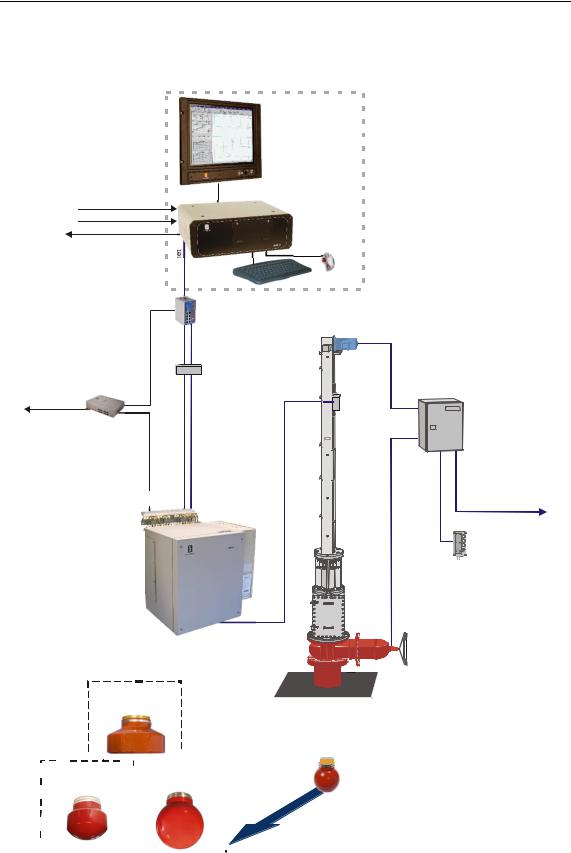
HiPAP® system with Transceiver unit Model x81
Operator
Station
Motion sensor
Heading sensor
Data output
|
Ethern |
Ethernet |
Fibre A |
Responder
Driver Unit (option)
Responder
Responder sync. |
Fibre A |
Transceiver unit
Model x81
Ethernet |
|
Hull |
|
switch/ |
|
|
|
|
Unit |
|
|
Converter |
|
|
|
|
|
|
|
Fibre B |
|
|
|
Fibre Splice |
|
Hoist |
|
Box |
|
|
|
|
Junction |
Control Unit |
|
|
|
|
|
|
Box |
|
|
Fibre B (optional) |
|
1 Option |
2 Option |
|
|
|
Ethernet interfaced |
|
|
|
with APOS/APC |
|
|
|
Remote |
|
|
|
Control |
|
|
|
Unit |
HiPAP 100 transducer
|
|
|
|
|
|
|
|
|
|
|
|
|
|
|
|
|
|
|
|
|
|
|
|
|
|
|
|
|
|
|
|
|
|
|
|
|
|
|
|
|
|
|
|
|
|
|
|
|
|
|
|
|
HiPAP 350 |
|
|
|
|
|
|
HiPAP 500 |
|
|
|
|
|
|
|||||||||||||||||||||||||||||
|
|
|
|
|
|
|
|
|
|
transducer |
|
|
|
|
|
|
|||||||||||||||||||||||||||||||
|
|
|
|
|
transducer |
|
|
|
|
|
|
|
|
|
|
|
|
||||||||||||||||||||||||||||||
|
|
|
|
|
|
|
|
|
|
|
|
|
|
|
|
|
|
|
|
|
|
|
|
|
|
|
|
|
|
|
|
|
|
|
|
|
|
|
|
|
|
|
|
|
|
|
|
|
|
|
|
|
|
|
|
|
|
|
|
|
|
|
|
|
|
|
|
|
|
|
|
|
|
|
|
|
|
|
|
|
|
|
|
|
|
|
|
|
|
|
|
|
|
|
|
|
|
|
|
|
|
|
|
|
|
|
|
|
|
|
|
|
|
|
|
|
|
|
|
|
|
|
|
|
|
|
|
|
|
|
|
|
|
|
|
|
|
|
|
|
|
|
|
|
|
|
|
|
|
|
|
|
|
|
|
|
|
|
|
|
|
|
|
|
|
|
|
|
|
|
|
|
|
|
|
|
|
|
|
|
|
|
|
|
|
|
|
|
|
|
|
|
|
|
|
|
|
|
|
|
|
|
|
|
|
|
|
|
|
|
|
|
|
|
|
|
|
|
|
|
|
|
|
|
|
|
|
|
|
|
|
|
|
|
|
|
|
|
|
(Cd31053a)
303490/H |
5 |
HiPAP® Model 501/451/351/101
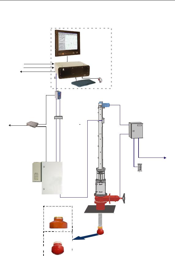
HiPAP® system with Transceiver unit Model x21
Operator
Station
Motion sensor
Heading sensor
Data output
Ethern
|
|
Ethernet |
Hull |
|
|
|
|
switch/ |
|
|
|
|
|
Converter |
Unit |
|
|
Ethernet |
Fibre A |
Fibre B |
|
|
|
Responder |
|
Fibre Splice |
Junction |
Hoist |
|
Driver Unit (option) |
|
Box |
Control Unit |
||
|
Box |
||||
Responder |
|
|
|
|
|
|
|
|
|
|
|
Responder sync. |
Fibre A |
Fibre B (optional) |
|
1 Option |
2 Option |
|
|
|
|
|
Ethernet interfaced |
Transceiver unit |
|
|
|
|
with APOS/APC |
|
|
|
|
|
|
Model x21 |
|
|
|
|
Remote |
|
|
|
|
|
Control |
|
|
|
|
|
Unit |
HiPAP 100 |
|
transducer |
(Cd31053) |
|
HiPAP 350 transducer
6 |
|
|
|
|
|
|
|
|
|
|
|
|
|
|
|
|
|
303490/H |
|
|
|
|
|
|
|
|
|
|
|
|
|
|
|
|
|
||
|
|
|
|
|
|
|
|
|
|
|
|
|
|
|
|
|
||
|
|
|
|
|
|
|
|
|
|
|
|
|
|
|
|
|
||
|
|
|
|
|
|
|
|
|
|
|
|
|
|
|
|
|
||
|
|
|
|
|
|
|
|
|
|
|
|
|
|
|
|
|
||
|
|
|
|
|
|
|
|
|
|
|
|
|
|
|
|
|
||
|
|
|
|
|
|
|
|
|
|
|
|
|
|
|
|
|
||
|
|
|
|
|
|
|
|
|
|
|
|
|
|
|
|
|
System description
HiPAP® redundant system
Example of a HiPAP® redundant system:
Operator Station |
Operator Station |
Operator Station |
Motion sensor |
|
Motion sensor |
|
|
|
Motion sensor |
|
|
|
|
|||
Heading sensor |
|
Heading sensor |
|
|
|
|
|
|
|
|
Heading sensor |
||
|
|
|
|
|||
GPS |
|
GPS |
|
|
|
|
|
|
|
|
GPS |
||
|
|
|
|
|||
|
|
|
|
|
|
|
Ethernet |
|
Ethernet |
|
Ethernet |
Ethernet |
|
Responder |
switch/ |
switch/ |
Responder |
|
Converter |
Converter |
Dual Ethernet |
|
|
|
|
|
|
|
(Cd31085) |
Fibre A |
Fibre B (optional) |
(Sync for Dual HiPAP only) |
Fibre A |
Fibre B (optional) |
|
Hull Unit |
|
HiPAP 500 |
Hull Unit |
|
HiPAP 500 |
|
|
Transceiver Unit |
|
|
Transceiver Unit |
|
|
Model x81 |
|
|
Model x81 |
Power A |
|
|
|
Power A |
|
|
Power B |
|
|
|
Power B |
|
|
(option) |
|
|
|
(option) |
|
|
|
Hoist |
|
|
|
Hoist |
|
Power |
Control Unit |
|
Power |
Control Unit |
|
|
|
|
|
|
|
||
|
|
|
Power |
|
Power |
Ethernet interfaced |
|
|
|
|
|
||
|
|
Ethernet interfaced |
|
|
with APOS/APC |
|
|
|
|
Option 2 |
|
||
|
|
with APOS/APC |
|
|
||
|
|
|
|
|
||
Gate valve |
|
Option 2 |
|
|
|
Remote |
|
|
|
Gate valve |
Option 1 |
||
|
|
Remote |
Control |
|||
|
|
|
|
|||
|
Option 1 |
|
|
|||
|
Control |
|
|
Unit |
||
Gate valve |
|
|
Gate valve |
|
||
position indicator |
|
Unit |
position indicator |
|
||
HiPAP 500/350 |
HiPAP 500/350 |
|
transducer |
||
transducer |
||
|
303490/H |
7 |

HiPAP® Model 501/451/351/101
Operator station
The operator station may be configured in two ways:
1.Stand alone
Computer
Display
Keyboard
Trackball
The stand alone configuration can be fitted as:
Contained in a standard 19” rack
The display and the computer are fitted into a standard
19” rack unit. The keyboard and the trackball may be placed on a desk, or on a suitable shelf. The transceiver unit is installed close to the hull unit.
The display, the computer and the keyboard are fitted into drawers in a standard 19” rack unit.
Desktop system
The display, the computer, the keyboard and the trackball sit on a desk top or a purpose-built shelf.
2.Operator console
If the HiPAP® system is delivered together with a Kongsberg DP system the operator station may be installed in a standard Kongsberg DP console.
Transceiver unit (system-specific)
Two types of transceiver units are available:
HiPAP® Transceiver unit Model x81are used for the systems 501, 451 and 351.
HiPAP® systems used with Transceiver unit Model x81, see figures on pages 5 and 7.
HiPAP® Transceiver unit Model x21 are used for the systems 351 and 101.
8 |
303490/H |

System description
HiPAP® systems used with Transceiver unit Model x21, see figure on page 6.
Hull unit (system-specific)
Hull units w/transducer, gate valves, Hoist Control Unit with Ethernet interface are described in the HiPAP® hull units Model 501/451/351/101 Instruction Manual.
APOS
The HiPAP® system is operated from APOS, a Windows based software system. The system can be operated from one single APOS station or from a wide number of APOS operator stations connected on a network.
Sensors
The HiPAP® system has a wide range of interfaces to sensors from different manufacturers.
The HiPAP® system needs high accuracy heading, roll and pitch sensors to be interfaced.
The accuracy of the sensors has direct impact on the position.
Conversion kits for upgrading of an “old” HiPAP® system
Transceiver unit Model x81 to be used with a transducer cable with plug.
See information on page 59
Transceiver unit Model x21 to be used with a transducer cable with plug.
See information on page 63
For more information, contact Kongsberg Maritime.
303490/H |
9 |

HiPAP® Model 501/451/351/101
System units - short description
Topics
Operator Station on page 10
Keyboard on page 11
Trackball on page 11
Display on page 11
1PPS converter on page 11
Ethernet switch/ Converter on page 11
Fibre Splice Box on page 12
Transceiver units on page 12
Operator Station
The HiPAP® System is operated through either one or several
Operator Stations.
The Operator Station consists of the following main units:
A Windows™ based personal computer
A display for presentation of information
Keyboard and mouse
The same computer is used for all types of installation, desktop or rack with additional mounting brackets or rails as required.
Power
The computer can be powered from either a 115 VAC or 230
VAC supply.
USB disk
An USB disk containing programs for backup and restore is delivered at the system setup. These programs can only be used when the system boots from the USB disk.
10 |
303490/H |

System description
Keyboard
The keyboard is a PS/2 keyboard. It is a QWERTY keyboard with US layout and includes back-lighting.
Trackball
The trackball is a standard trackball with a scroll wheel and three buttons.
Display
Refer to the separate manual supplied with the display.
1PPS converter (option)
The 1PPS converter is an option to a standard HiPAP® system. 1PPS; One Pulse per Second.
The signal is normally taken from a GPS receiver or a time synchronize unit.
This pulse is used to synchronize the clock on the APOS/HiPAP system with a reference clock.
In addition to the pulse, a message with correct time must be transmitted on the same serial line as used for the 1PPS input.
A 1PPS converter passes the RS-232 GPS Position Data through but shapes the 1PPS pulse to a fixed pulse length and converts it from TTL level to RS-232 level.
(Cd31162)

Figure 1 1PPS converter
Ethernet switch/Converter
The Ethernet switch/Converter is used for:
Interface Optical fibre cable to transceiver
303490/H |
11 |

HiPAP® Model 501/451/351/101
Responder Driver Unit
Hoist Control Unit with Ethernet
Gate Valve Main Control Unit with Ethernet
Fibre Splice Box
The Fibre Splice Box has eight (8) ports. This box is used to splice the system fibre-optic cables.
Transceiver units
The HiPAP® transceiver units are steel cabinets, containing a rack holding the system electronics modules. The units are fitted with an air to air heat exchange unit.
The transceiver units are designed to be mounted on a suitable bulkhead and are fitted with vibration/shock absorbers to reduce the effects of transceiver unit vibrations.
Topics
Transceiver unit Model x81 on page 13
Transceiver unit Model x21 on page 14
12 |
303490/H |
System description
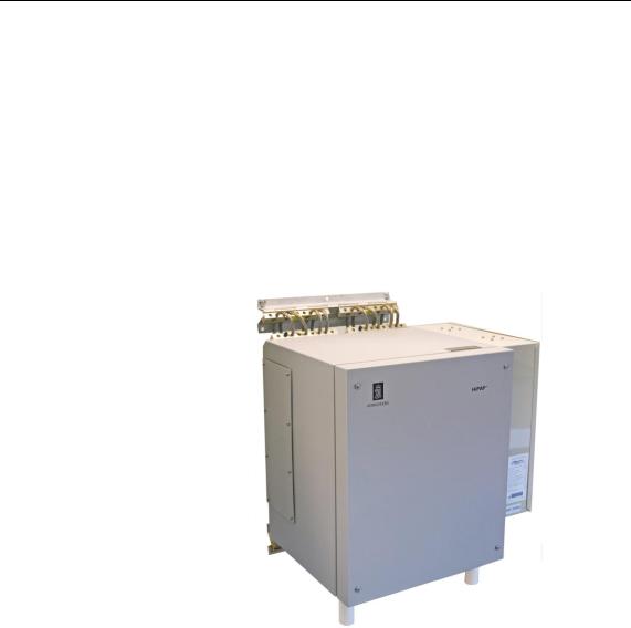
Transceiver unit Model x81
Transceiver unit x81 may be delivered with:
With the air to air heat exchange unit mounted on the right side as standard.
or
With the air to air heat exchange unit mounted on the unit door (optional).
An access door for plugging connectors and service is located on the left side of the unit.
Figure 2 Standard Transceiver unit Model x81 w/air to air heat exchange unit mounted on the right side
Used for the HiPAP® 501 with eight (8) TRX32 boards
Used for the HiPAP® 451 with two (2) TRX32 boards
Used for the HiPAP® 351 with two (2) TRX32 boards
Used for the HiPAP® 101 with one (1) TRX32 board
System upgrade
The HiPAP® 451 can be upgraded to full HiPAP® 501 performance. This is done by:
Installation of 6 additional transmitter/receiver boards (TRX32) in the transceiver unit.
APOS software upgrade.
303490/H |
13 |
HiPAP® Model 501/451/351/101
Connections
All cables to and from the transceiver unit enter the unit through the base of the unit.
Power
The transceiver unit is powered from a 230 Vac supply. The power switch (Main switch) is located inside the transceiver unit.
Refer to figure on page 80
If you only have 110 Vac power available, you must use a 110 Vac to 230 Vac transformer - see page 15.
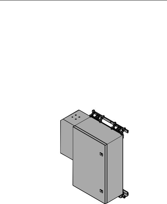
Transceiver unit Model x21
Transceiver unit x21 are delivered with the air to air heat exchange unit mounted on the left side.
(Cd31072)
Figure 3 Transceiver unit Model x21
Used for the HiPAP® 351 with two (2) TRX32 boards
Used for the HiPAP® 101 with one (1) TRX32 board
Connections
All cables to and from the transceiver unit enter the unit through the base of the unit.
14 |
303490/H |

System description
Power
The transceiver unit is powered from a 230 Vac supply. The power switch (Main switch) is located inside the transceiver unit.
Refer to figure on page 91
If you only have 110 Vac power available, you must use a 110 Vac to 230 Vac transformer - see page 15.
110 Vac to 230 Vac transformer - option for both transceiver units
If your only have 110 Vac power available, an external transformer from 110 Vac to 220 Vac must be installed on the main power line to both the Transceiver unit Model x81 and the Transceiver unit Model x21
Order no see page 20
303490/H |
15 |

HiPAP® Model 501/451/351/101
3 TECHNICAL SPECIFICATIONS
This chapter gives the technical specifications of the HiPAP® system units.
Topics
Operator station on page 17
Fibre Splice Box on page 17
Ethernet switch/Converter on page 18
Transceiver unit Model x81 on page 18
Transceiver unit Model x21 on page 20
110 Vac to 230 vac transformer - option on page 20
SSBL accuracy on page 20
LBL accuracy on page 25
Range capabilities on page 27
Fibre-optic cable on page 28
Related topics
Transmit on external trigger on page 105
16 |
303490/H |
Loading...