

Kongsberg EM 712 Installation Manual

KongsbergEM712
Multibeamechosounder
Installationmanual
401027/B
June2018©KongsbergMaritimeAS

Copyright
©CopyrightKongsbergMaritimeAS
TheinformationcontainedinthisdocumentremainsthesolepropertyofKongsbergMaritimeAS.Nopart
ofthisdocumentmaybecopiedorreproducedinanyformorbyanymeans,andtheinformationcontained
withinitisnottobecommunicatedtoathirdparty ,withoutthepriorwrittenconsentofKongsberg
MaritimeAS.Thedocument,oranypartofit,maynotbetranslatedtoanyotherlanguagewithoutthe
writtenapprovalfromKongsbergMaritimeAS.
Disclaimer
KongsbergMaritimeASendeavourstoensurethatallinformationinthisdocumentiscorrectandfairly
stated,butdoesnotacceptliabilityforanyerrorsoromissions.
Warning
Theequipmenttowhichthismanualappliesmustonlybeusedforthepurposeforwhichitwasdesigned.
Improperuseormaintenancemaycausedamagetotheequipmentand/orinjurytopersonnel.Allusers
mustbefamiliarwiththecontentsoftheappropriatemanualsbeforeattemptingtoinstall,operate,
maintainorinanyotherwayworkontheequipment.
KongsbergMaritimeASdisclaimsanyresponsibilityfordamageorinjurycausedbyimproperinstallation,
useormaintenanceoftheequipment.
Supportinformation
Ifyourequiremaintenanceorrepair,contactyourlocaldealer.Y oucanalsocontactususingthefollowing
address:km.hydrographic.support@kongsberg.com.Ifyouneedinformationaboutourotherproducts,
visithttp://www.km.kongsberg.com.
KongsbergMaritimeAS
www.kongsberg.com

Installationmanual
Tableofcontents
ABOUTTHISMANUAL..............................................................7
KONGSBERGEM712................................................................9
Systemdiagram0.5x0.5degreessystem.......................................................................10
Systemunits.....................................................................................................................12
Transducerdescription...........................................................................................12
TransmitterUnitdescription...................................................................................13
ReceiverUnitdescription.......................................................................................13
ProcessingUnitdescription....................................................................................14
HydrographicWorkStationdescription.................................................................14
PREPARATIONS.....................................................................15
Tools,equipmentandconsumablesrequiredforEM712installation.............................15
Personnelqualications...................................................................................................16
Sonarroomrequirements.................................................................................................17
Environmentalrequirements..................................................................................17
Sizeandaccessrequirements.................................................................................17
Requirementsforinsulation,heatingandventilation.............................................18
Requirementsforelectricalinstallations,cablesandcommunication...................18
Wheretoinstallthetransducer........................................................................................20
Introductiontotransducerlocation.........................................................................20
Mountthetransducerdeep.....................................................................................20
Avoidprotrudingobjectsnearthetransducer.........................................................21
Keepthetransducerfarawayfromthepropellers.................................................22
Chooseatransducerpositionfarawayfromthebowthruster(s)...........................22
Summaryandgeneralrecommendations...............................................................22
Acousticnoise..................................................................................................................24
Contributingfactors................................................................................................24
Selfnoise................................................................................................................25
Ambientnoise.........................................................................................................28
Electricalselfnoise................................................................................................28
Somemeanstoreduceacousticnoise....................................................................28
INSTALLINGTHETRANSDUCER.............................................31
Transducerdescription.....................................................................................................32
Transducerinstallationprinciples....................................................................................34
Introduction............................................................................................................34
Gondola..................................................................................................................36
Blister.....................................................................................................................37
Flushmounted........................................................................................................38
401027/B
3

KongsbergEM712
Externalmountedwithfairings..............................................................................38
Transducerinstallationsummary.....................................................................................39
Manufacturingandinstallingthecasings........................................................................42
Designing,manufacturingandmountingthesteelconduits............................................44
Installingthemountingframes........................................................................................47
Installingthetransducersintothemountingframes........................................................49
Rulesfortransducerhandling..........................................................................................53
Paintingthetransducerface.............................................................................................54
Approvedanti-foulingpaints...........................................................................................56
INSTALLINGTHEEM712HARDWAREUNITS.........................58
TransmitterUnit...............................................................................................................59
InstallingtheTransmitterUnit...............................................................................60
RIO-Pboard-dipswitchsetting............................................................................62
ReceiverUnit...................................................................................................................63
InstallingtheReceiverUnit....................................................................................64
ReceiverUnit-dipswitchsetting..........................................................................66
ProcessingUnit................................................................................................................68
CBMFboard-dipswitchsetting...........................................................................69
DRAWINGFILE......................................................................70
216148EM712TransducerTX1dimensions.................................................................71
221048EM712TransducerTX2dimensions.................................................................73
219621EM712TransducerRX1dimensions.................................................................75
216146EM712TransducerRX2dimensions.................................................................77
223137EM712Transducermountingframe-0.5degrees............................................79
223139EM712Transducermountingframe-1degree.................................................81
223273EM712Transducermountingframe-2degrees...............................................83
317812EM712Casingw/mountingframe-0.5degrees...............................................85
320320EM712Casingw/mountingframe-1degree....................................................86
375817EM712Combinedcasingw/mountingframe-1degree...................................87
331369EM712Casingw/mountingframe-2degrees..................................................88
396402EM712TransmitterUnitdimensions.................................................................89
212984EM712TransmitterUnitmountingbracket.......................................................90
396428EM712ReceiverUnitdimensions.....................................................................91
385422ProcessingUnitdimensions................................................................................92
378828HydrographicW orkStationdimensions.............................................................93
371591Rackinstallationkitdimenisons.........................................................................95
370275RemoteControlUnit(K-REM)dimensions.......................................................96
373962RemoteControlUnit(K-REM)wiringdiagram.................................................98
DIMENSIONALSURVEYINGANDALIGNMENT........................99
Aboutdimensionalsurveyingandalignment................................................................100
4
401027/B

Installationmanual
Dimensionalsurveying..................................................................................................100
Alignment......................................................................................................................101
Calibration.....................................................................................................................102
Vesselcoordinatesystem...............................................................................................102
CABLELAYOUTANDINTERCONNECTIONS...........................104
Readthisrst.................................................................................................................105
Cableplans.....................................................................................................................106
Cableplan,ProcessingUnit.................................................................................107
Cableplan,TransmitterUnit................................................................................108
Cableplan,ReceiverUnit,0.5degree..................................................................110
Topsidecableplan................................................................................................113
ListofEM712cables....................................................................................................113
Transmittransducercables.............................................................................................119
Receivetransducercables..............................................................................................123
Clocksynchronization(1PPS).......................................................................................127
Externalsynchronization...............................................................................................129
HydrographicWorkStationrearconnectors(MP5810)...............................................132
Cabledrawingsandspecications.................................................................................134
RS-232seriallineusingthreewiresandRJ45connector....................................135
RS-422seriallineusingvewiresandRJ45connector......................................136
AdapterforD-connectortoRJ45connectorforRS-422.....................................137
Clocksynchronisation(1PPS)usingacoaxcable...............................................138
Externalsynchronisation......................................................................................139
Remotecontroloverview.....................................................................................140
Remotecontrol.....................................................................................................142
RemoteControlusingK-Rem..............................................................................143
Dummyplugfornotusingremotecontrol...........................................................144
RemotecontrolofTransmitterUnit.....................................................................145
RemotecontrolofReceiverUnit..........................................................................147
TECHNICALSPECIFICATIONS..............................................151
Performancespecications............................................................................................152
Interfacespecications...................................................................................................154
Weightandoutlinedimensions......................................................................................158
Powerrequirements.......................................................................................................160
Environmentalrequirements..........................................................................................161
Alignmentspecications................................................................................................164
EQUIPMENTHANDLING.......................................................166
TransportingKongsbergMaritimeequipment...............................................................167
Liftingunitsandtransportationboxes...........................................................................168
Inspectionofunitsandtransportationboxesafterarrival..............................................170
401027/B
5

KongsbergEM712
Specicationsforstoragepriortoinstallationoruse.....................................................171
Unpackinginstructions..................................................................................................173
Unpackingstandardpartsandunits......................................................................173
Unpackingmechanicalunits................................................................................174
Unpackingelectronicandelectromechanicalunits..............................................175
Unpackingtransducers.........................................................................................176
Specicationsforstorageafterunpacking.....................................................................178
6
401027/B

Aboutthismanual
Purposeofmanual
Thepurposeofthismanualistoprovidetheinformation,proceduresandbasicdrawings
requiredforthephysicalinstallationoftheEM712.
Targetaudience
Aboutthismanual
Themanualisintendedfortechnicalpersonnel;suchasskilledshipyardworkers,
electricians,qualiedengineersandnavalarchitects.Itisassumedthatyouunderstand
thegeneralprinciplesofmaritimeelectronicequipment.Youmustalsobefamiliarwith
computerhardware,interfacetechnologyandinstallationofelectronicandmechanical
products.
Weassumethatyouarefamiliarwiththebasicacousticprinciplesofsoundinwater.
Wealsoexpectthatyouhavesomeexperiencewithmultibeamand/orsinglebeamecho
soundersinhydrographicapplications..
Installationinstructions
Youmustfollowtheinstructionsinthismanualtoensureoptimalperformance.Asa
guide,installationproceduresarepresentedintheordertheymustbedone.
Theequipmentdescribedinthismanualincludesthecompletesystemwithrelevant
cabinets.Unitsprovidedlocallybythecustomer,installationshipyardorlocal
representativearenotdescribed.
Themanualalsodenestheequipmentresponsibility,andprovidesapplicable
instructionsforunpackingandstorageofunits.
Note
Youmustfollowtheinstructionsgiveninthismanual.Ifnotitmayaffectthewarranty.
KongsbergMaritimeASwillacceptnoresponsibilityforanydamageorinjurytothe
system,vesselorpersonnelcausedbyequipmentthathasbeenincorrectlyinstalledor
maintained,orbydrawings,instructionsorproceduresthathavenotbeenprepared
byus.
401027/B
7

KongsbergEM712Installationmanual
Installationdrawings
Theinstallationshipyardmustprovideallnecessaryinstallationdrawingsunless
otherwisespeciedinthedeliverycontract.
KongsbergMaritimeASmay,onspecialorder,provideassistancetothesedrawings.
Note
Ifrequired,alldocumentsprovidedbytheshipyardforthephysicalinstallationof
theEM712mustbeapprovedbythevessel’ snationalregistryandcorresponding
maritimeauthorityand/orclassicationsociety.Suchapprovalmustbeobtainedbefore
theinstallationcanbegin.Theshipownerandshipyarddoingtheinstallationare
responsibleforobtainingandpayingforsuchapproval.
TheoutlinedimensionsoftheEM712unitsarefoundintheDrawinglechapter
inthismanual.
Onlineinformation
ForinformationabouttheEM712andotherproductsfromKongsbergMaritime,visit
ourwebsite.
•https://www.km.kongsberg.com
Registeredtrademarks
Observetheregisteredtrademarksthatapply.
Windows
®
isaregisteredtrademarkofMicrosoftCorporationintheUnitedStatesand
othercountries.
®
EM
isaregisteredtrademarkofKongsbergMaritimeASinNorwayandothercountries.
8
401027/B

KongsbergEM712
Topics
Systemdiagram0.5x0.5degreessystem,page10
Systemunits,page12
KongsbergEM712
401027/B
9
KongsbergEM712Installationmanual
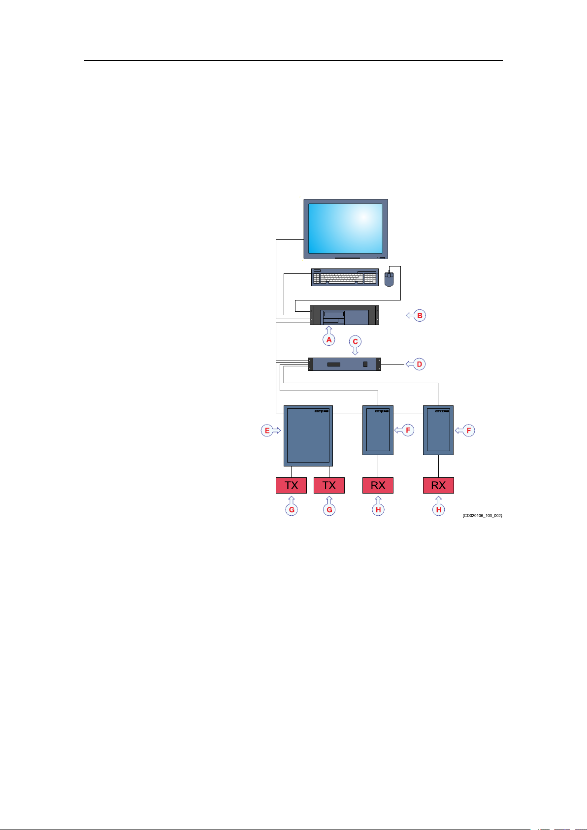
Systemdiagram0.5x0.5degreessystem
ThesystemdiagramidentiesthemaincomponentsofabasicEM712system.Only
themainconnectionsbetweentheunitsareshown.Detailedinterfacecapabilitiesand
powercablesarenotshown.
AHydrographicWorkStation(HWS)
BInterfaces:
•Soundspeedsensor
•Tide
•Centerdepthoutput
CProcessingUnit(PU)
10
401027/B

DProcessingUnitinterfaces:
•Positioningsystems
•Attitude(roll,pitchandheave)
•Velocity
•Heading
•Clock
ProcessingUnitspecialinterfaces:
•Triggerinput/output
•Clocksynchronization(1PPS)
ETransmitterUnit
FReceiverUnit
GTransmittransducer
KongsbergEM712
HReceivetransducer
401027/B
11
KongsbergEM712Installationmanual
Systemunits
Topics
Transducerdescription,page12
TransmitterUnitdescription,page13
ReceiverUnitdescription,page13
ProcessingUnitdescription,page14
HydrographicWorkStationdescription,page14
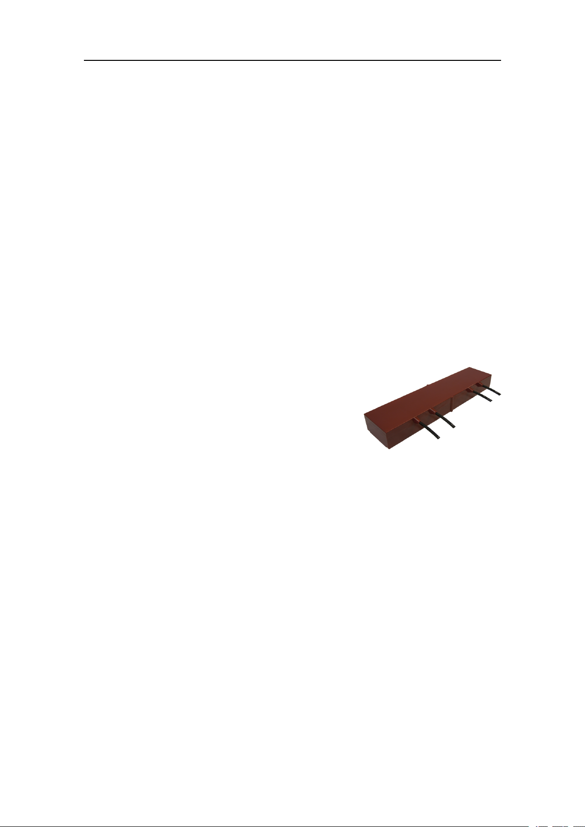
Transducerdescription
Atransducerisadevicethatconvertsoneformofenergytoanother.Inanechosounder
systemthetransducerconvertsbetweenelectricenergyandsound.
TheEM712usesseparatetransducerarraysfor
transmittingandreceivingsoundpulses.Both
transducerarrayscanhaveoneormoremoduleswhich
areassembledinmountingframes.
TheEM712transducermodulesareavailableinan
icereinforcedversion.Formoreinformation,contact
KongsbergMaritime.
Thetwotransducerarraysarenormallymountedas“T”or“L”congurationsunderthe
vessel’shull(MillsCrossconguration).Thetransmittransducerarrayshouldbealigned
paralleltothevessel’skeel.Thereceivertransducerarrayshouldbealigned90degrees
onthekeel.Bothtransducerarraysshouldbehorizontalonaplaneonthekeel.
12
401027/B
KongsbergEM712
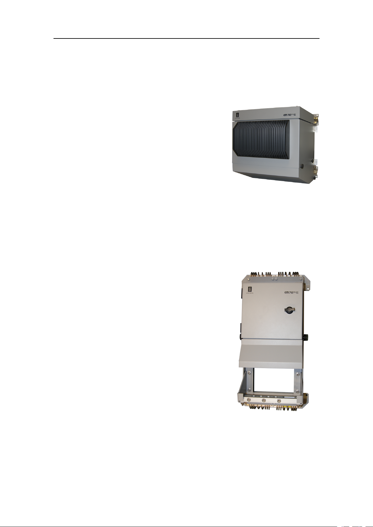
TransmitterUnitdescription
TheEM712TransmitterUnithasalltransmitelectronics,likecontrolprocessors,power
ampliers,powersupply,capacitorbatteryandEthernetinterface.
TheTransmitterUnitisawall-mountedsteelcabinet
withintegratedshockandvibrationabsorbers,designed
forbulkheadmounting.One19inchsub-rackis
containedinthecabinet.Thenumberofcircuitboards
inthesub-rackwilldependuponthechosentransducer
conguration.
TwistedpairEthernetisusedfordatacommunication
withtheProcessingUnit.
TheTransmitterUnitisnormallylocatedina"sonar
room"closetothetransducerarrays.
Fora0.5degreetransducer,oneTransmitterUnitisused.
ReceiverUnitdescription
TheEM712ReceiverUnithasallreceiveelectronics,likecontrolprocessor,ampliers,
Analog-to-DigitalConverters,powersupplyandEthernetinterface.
TheReceiverUnitisasmallwall-mountedsteelcabinet
withintegratedshockandvibrationabsorbers,designed
forbulkheadmounting.Thenumberofcircuitboards
willdependuponthechosentransducerconguration.
TwistedpairEthernetisusedfordatacommunication
withtheProcessingUnit.
TheReceiverUnitisnormallylocatedina"sonar
room"closetothetransducerarrays.
Fora0.5degreetransducer,twoReceiverUnitsare
used.
401027/B
13
KongsbergEM712Installationmanual
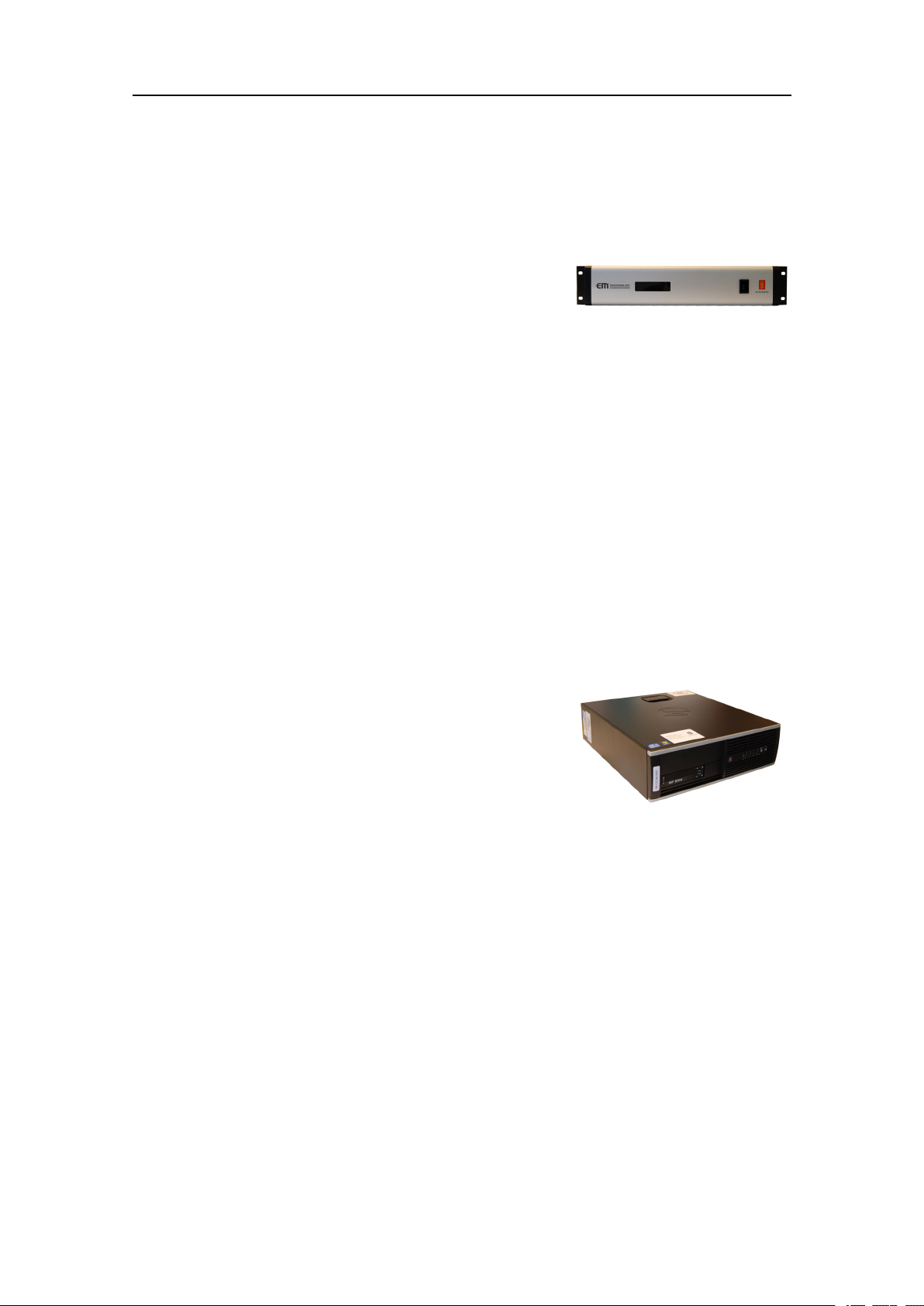
ProcessingUnitdescription
TheEM712ProcessingUnitisprovidedtoprocessthesignalstoandfromthe
TransmitterandReceiverUnits.
TheEM712ProcessingUnitisanindustrial
computerusingbothCOTS(commercialoff-the-shelf)
componentsandcustommadecomponents.Theunitis
designedandtestedforruggeduse.
TheProcessingUnitperformsthereceiverbeamforming,bottomdetection,andmotion
andsoundspeedcorrections.Itcontainsallinterfacesfortime-criticalexternalsensors
suchasvesselattitude(roll,pitch,headingandheave),vesselpositionandexternal
clock.Morethanonesensorofeachtypemaybeconnectedsimultaneously,withonein
useandallofthemlogged.
TheProcessingUnitcontrolstheTransmitterandReceiverunitsviaEthernet
communication,andisalsointerfacedtotheOperatorstationviaEthernet.
The48VoutputfromtheProcessingUnitcanbeusedforremoteon/offcontrolofthe
TransmitterandReceiverUnits.
HydrographicWorkStationdescription
TheHydrographicWorkStationistheoperatorstationfortheEM712.
Adedicatedmaritimecomputerisprovidedwiththe
EM712Multibeamechosounder.Itissetupwith
allnecessarysoftware.
TheHydrographicWorkStationisbasedonthe
Microsoft
TheHydrographicWorkStationisnormallymounted
neartheoperatorworkspace.
®
64-bitWindows®7operatingsystem.
14
401027/B

Preparations
Topics
Tools,equipmentandconsumablesrequiredforEM712installation,page15
Personnelqualications,page16
Preparations
Sonarroomrequirements,page17
Wheretoinstallthetransducer,page20
Acousticnoise,page24
Tools,equipmentandconsumablesrequired forEM712installation
InordertodotheEM712installation,allnecessarytoolsandequipmentformechanical
work,cabinetinstallationandelectricalwiringmustbeavailable.
Itisnotpracticaltoprovideadetailedlistofallnecessarytoolsandequipment.Y oumust
beequippedwithastandardsetoftools.Thistoolsetmustcomprisethenormaltoolsfor
electronicandelectromechanicaltasks.Thisincludesdifferentscrewdrivertypes,pliers,
spanners,acablestripper,asolderingironetc.Eachtoolmustbeprovidedinvarious
sizes.Werecommendthatalltoolsaredemagnetizedtoprotectyourequipment.
However,youmustmakesurethatthefollowingspecializedtoolsareavailable.
•Allnecessarytoolsandconsumablesrequiredforwelding
•Allnecessarytoolsandconsumablesrequiredforphysicalinstallationofunits,
cabinetsandracks
•Allnecessarytoolsandconsumablesrequiredforelectricalinstallations
•AnarticulatedjackorsimilararrangementcapableofliftingtheindividualEM712
units
401027/B
15

KongsbergEM712Installationmanual
Note
Wheneverspecicconsumablesorspecialtoolsortestinstrumentsarerequired,these
areidentiedintherelevantprocedure(s).
Relatedtopics
Weightandoutlinedimensions,page158
Personnelqualications
TheinstallationoftheEM712isademandingtask.Itisveryimportantthatthe
personnelinvolvedintheinstallationtasksarecompetentandexperiencedcraftsmen.
Asaminimum,thefollowingcertiedcraftsmenmustbeavailable.
•ServiceengineerfromKongsbergMaritime
•Welders
•Electricians
Note
Thequalityoftheweldingiscriticaltothesafetyofthevessel.Weldingmustonlybe
donebyacertiedwelder.
Ifapplicable,thenalinstallationweldsmustbeapprovedbythevessel’ snational
registry,thecorrespondingmaritimeauthorityand/orclassicationsociety.Observethe
relevantrulesandregulationsrelatedtowelding.
16
401027/B

Preparations
Sonarroomrequirements
Topics
Environmentalrequirements,page17
Sizeandaccessrequirements,page17
Requirementsforinsulation,heatingandventilation,page18
Requirementsforelectricalinstallations,cablesandcommunication,page18
Environmentalrequirements
TheEM712unitsmustbeinstalledinadryanddust-freeenvironment.Theunitsarenot
fullyprotectedagainsthumidity,dustorwater.
Itisimportantthatthesonarroomiskeptdry.TheEM712unitsmustnotbeexposed
toexcessivetemperatures,moistureorhumidity.Suchconditionscancausecorrosive
attacksandsubsequentfailurestotheelectroniccircuitry.Visitthesonarroomat
regularintervalstochecktemperatureandhumidity,andtakethenecessaryactions
iftheenvironmentalconditionsarepoor.
ObservetheenvironmentalspecicationsrelatedtotheEM712units.
Relatedtopics
Environmentalrequirements,page161
Sizeandaccessrequirements
Awelldesignedsonarroomwithawellttedsizeandeasyaccessreducestheriskof
corrosion,andsimpliesmaintenance.Thisincreasessystemreliability.
Thesonarroommustbelargeenoughtohouseallthesystemunits.Theroommust
provideenoughspacetoallowefcientmaintenance.Youmustbeabletokeepallthe
cabinetdoorsfullyopenwithoutunduerestrictiontoyourmovements.
1Theroommustnotbeusedforanyotherheavymachinery.
2Theroommustnotbeunnecessarilyobstructedbygirders,pipesetc,whichmay
causeinstallationproblemsorimpedemaintenance.
3Thesonarroommustbeaccessibleunderallconditionsatseaorataberth.
4Alldoorsorhatchesmustbedesignedsothatthetoolsandequipmentcanbe
removedwithoutbeingdisassembled.
Relatedtopics
Weightandoutlinedimensions,page158
401027/B
17

KongsbergEM712Installationmanual
Requirementsforinsulation,heatingandventilation
Thebulkheadsinthesonarroomshouldbeinsulatedandprovidedwithaninteriorwall
tothedeck.Theroomshouldbeequippedwithheaterandconnectedtothevessel's
ventilationsystem.
Heatingrequirements
Heatingisaneffectivemethodforreducinghumidity.Theheaterinthesonarroommust
dimensionedtomaintaintheequipmentwithinitsenvironmentaltolerances.
ObservetheenvironmentalspecicationsrelatedtotheEM712units.
Ventilationrequirements
Thesonarroomshouldbeconnectedtothevessel'sventilationsystemtoensureasupply
ofcoolingair.Ifaventilationsystemisnotavailable,installtwo3”pipesfromthesonar
roomtoasuitablefreshairlocationondeck.
Thefreshairshouldentertheroomasclosetotheooraspossible,andshouldbe
extractedfromashighaspossible.Afunnelshapeddrip-collectormustbemounted
belowtheventpipestodivertmoisturetothebilge.Onthemaindeck,thebest
ventilationisprovidedwhentheoutletpipeisatleastfourmetershigherthantheinlet
pipe.Tokeepoutseawater,rainandspray,theventilationpipesmustbettedwith
goosenecksoranequivalentdesign.
Note
Ifthevesselislikelytooperateintropicalconditions,asuitableairconditioningsystem
mustbeinstalled.Theairconditioningsystemmustbeabletoprovideanambient
temperaturethatdoesnotexceedthemaximumoperatingtemperaturesoftheEM712
unitsthatareinstalledintheroom.
Relatedtopics
Environmentalrequirements,page161
Requirementsforelectricalinstallations,cablesand communication
Theelectricalinstallationsinthesonarroommustmeetminimumrequirementsto
providesuitablelightsandsupplypower.
Lightrequirements
Thesonarroommustbeequippedwithsuitablelightingtosimplifytheinstallation
andtoaidfuturemaintenance.
18
401027/B

Preparations
Communicationrequirements
Thesonarroomshouldbeequippedwithatelephone,anintercomsystem,oranyother
meansoforalcommunicationbetweenthesonarroomandthebridgeand/orcontrol
room(s).
Powerrequirements
Eachunitinthesonarroomshouldbeprovidedwithaseparatecircuitbreakeronthe
mainssupply.
Propervesselgroundmustbeprovided.
Aminimumnumberofadditionalelectricaloutletsmustbeprovidedforotherequipment.
Cablingrequirements
ThesonarroomunitsareconnectedtootherEM712unitslocatedindifferent
compartmentsonthevessel.Theunitsmayalsobeconnectedtoperipheraldevices.If
thesecablespassthroughhatchesorareaswheretheymaybedamaged,theymustbe
runinconduits.Minimum2”conduitisrecommended.
Makesurethatallsystemcablesareproperlyconnectedandsecured,andinstalled
withsomeslack.Theslackisessentialtowithstandvibrations,andtofacilitatefuture
maintenanceandreplacements.
Relatedtopics
Powerrequirements,page160
401027/B
19

KongsbergEM712Installationmanual
Wheretoinstallthetransducer
Topics
Introductiontotransducerlocation,page20
Mountthetransducerdeep,page20
Avoidprotrudingobjectsnearthetransducer,page21
Keepthetransducerfarawayfromthepropellers,page22
Chooseatransducerpositionfarawayfromthebowthruster(s),page22
Summaryandgeneralrecommendations,page22
Introductiontotransducerlocation
Asingleanswertothequestion"wheretoinstallthetransducer"cannotbegiven.
Thephysicallocationofthetransducerdependsonthevessel'sdesignandconstruction,
howthehullisshaped,andhowthewaterrunsalongthehull.Therearehowevera
numberofimportantguidelines,andsomeoftheseareevenconicting.
Note
Theinformationheremustbeconsideredasgeneraladvice.EachEM712installation
mustbehandledseparatelydependingonthehulldesignandtheotherelectricaland
mechanicalsystemsinstalledonthevessel.
Mountthetransducerdeep
InordertoachievethebestpossibleEM712performance,mountthetransduceras
deepaspossibleunderthevessel’shull.
Thereareseveralreasonsforthisrecommendation.
Flownoise
Considerthesituationswhenthevesselisunloaded,andpitchinginheavyseas.The
vesselisridinghigh,andthebowmayevenbeliftedoutofthewater.Thiswillcausea
lotofairtofollowtheshapeofthehull.
Theupperwaterlayersoftheseacontainamyriadofsmallairbubblescreatedbythe
breakingwaves.Inheavyseastheupper5to10metresmaybelledwithair,andthe
highestconcentrationswillbenearthesurface.Airbubblesabsorbandreectthesound
energy,andtheymayinworstcasesblockthesoundtransmissionaltogether.
20
401027/B

Preparations
Cavitation
Cavitationistheformationofsmallairbubblesclosetothetransducerface.Thebubbles
appearbecausethelocalpressurebecomesnegativeduringpartsoftheacousticpressure
cycles.Thecavitationthresholdincreaseswiththehydrostaticpressure.Thenoiseis
madewhenthebubblesimplode.
Transmittinginair
Thetransducermustneverbeliftedfreeofthewatersurface.Ifthetransduceris
activatedwhenoutofwateritmaybedamagedbeyondrepair.Mountingthetransducer
atadeeppositiononthehullwillinnormallypreventthis.
Slamming
Slamminghappensifthevesselhullclimbsoutofthewaterinheavyseas.Theforceof
thewaterwhenthehullfallsdownmaypushthetransducerup,andmaycausedamage
bothtothetransducerandtoitsmounting.Thisisespeciallyimportantforlowfrequency
transducerswithlargefaces.Theeffectofslammingcanbereducedbymountingthe
transducerasdeepaspossibleonthehull.
Note
KongsbergMaritimeAStakesnoresponsibilityforanydamagestothetransducer,the
cableorthemountingarrangement,causedbyslamming.
Avoidprotrudingobjectsnearthetransducer
Objectsprotrudingfromthehullwillgenerateturbulenceandownoise.Thiswill
reducetheEM712performance.
Protrudingobjectsmaybezincanodes,transducersoreventhevessel'skeel.Holesand
pipeoutletsarealsoimportantnoisesources,aswellasroughsurfacescausedbybad
welding.Eventracesofsealingcompound,sharpedges,boltsoremptyboltholeswill
createnoise.Alltheseprotrudingobjectsmayactasresonantcavitiesamplifyingthe
ownoiseatcertainfrequencies.
Donotplaceatransducerinthevicinityofprotrudingobjects,andespeciallynotclose
behindthem.Makesurethatthesurfaceofthetransducerface,thehullplatingandputty
aroundthetransducerisasevenandsmoothaspossible.Mountingscrewsorboltsmust
notbeextrudingfromthetransducer,theinstallationhardwareorthehullplating.If
necessary,grindandpolishallsurfaces.
401027/B
21

KongsbergEM712Installationmanual
Keepthetransducerfarawayfromthepropellers
Thepropulsionpropellersisthedominantnoisesourceonmostvessels.Thenoise
iseasilytransmittedthroughthewater.Thisnoisemayoftenreducetheoverall
performanceofyourEM712.
Thetransducermustbeinstalledasfarawayfromthepropellersaspossible.Thebest
positionsarethereforeontheforepartofthehull.Positionsoutsidethedirectlineof
sightfromthepropellersarebest.
Onsmallvesselswerecommendmountingthetransduceronthatsideofthekeelwhere
thepropellerbladesmoveupwards.Thisisbecausethepropellercavitationisweakest
onthatside.Thecavitationstartswhenthewaterowsinthesamedirectionasthe
propellerblades.Thisiswherethepropellerbladesmovedownwards.
Chooseatransducerpositionfarawayfromthebow thruster(s)
Bowthrusterpropellersareextremelynoisy.Whenyoudecidewheretoplacethe
transducer,youmustconsiderthenoisecreatedbymostbowthrusters.
Wheninoperation,thenoiseandcavitationbubblescreatedbythethrustermaymake
yourEM712Multibeamechosounderuseless,almostnomatterwherethetransduceris
installed.Whenthebowthrustersarenotinoperation,thetunnelcreatesturbulence.If
yourvesselispitching,thetunnelmaybelledwithairoraeratedwaterintheupper
positionandreleasethisinthelowerposition.
Ingeneral,thetransducershouldthereforebeplacedwellawayfromthebowthruster(s).
However,thisisnotaninvariablerule.Certainthrusterdesigns-combinedwiththeir
physicallocationsonthehull-maystillofferasuitablelocationforthetransducer,even
closetothethruster.Ifyouareindoubt,consultanavalarchitect.
Summaryandgeneralrecommendations
Someoftheinstallationguidelinesprovidedfortransducerlocationmaybeconicting.
Forthisreason,eachvesselmustbetreatedindividuallyinordertondthebest
compromise.
Ingeneral,themostimportantfactoristoavoidairbubblesinfrontofthetransducer
face.Forthisreason,therecommendedtransducerlocationisnormallyintheforepartof
thehull,wellaheadofthenoisecreatedbythebowwave.
Themaximumdistancefromthebowisnormallyequaltoonethirdofthetotalwater
linelengthofthehull.
Ifthevesselhullhasabulbousbow,thismaywellbeagoodtransducerlocation,but
alsointhiscasetheowpatternoftheaeratedwatermustbetakenintoconsideration.
Theforemostpartofthebulbisoftenagoodlocation.
Thisappliestothevesselinnormaltrimandspeed.
22
401027/B

Preparations
Important
Thetransducermustneverbetiltedbackwardswhenthevesselismovingatnormal
speed.
Donotplaceatransducerinthevicinityofprotrudingobjects,andespeciallynotclose
behindthem.
Makesurethatthesurfaceoftheresultinginstallationisassmoothandstreamlinedas
possible.
401027/B
23

KongsbergEM712Installationmanual
Acousticnoise
Aswithanyotherhydroacousticsystems,thequalityoftheEM712echodataand
presentationsaresubjecttounwantedacousticnoise.Theechoesfromanylargeand
smalltargetmustbedetectedinsidethenoise.
Itisimportantthatwekeepthenoiselevelaslowaspossible.Theisnecessarytoobtain
longrangeanddependableinterpretationsoftheechoes.Evenwiththeadvancednoise
lteringofferedbytheEM712,wemustaddressthenoisechallenge.Thisisimportant
duringtheplanningandpreparationsfortheEM712installation.
Topics
Contributingfactors,page24
Selfnoise,page25
Ambientnoise,page28
Electricalselfnoise,page28
Somemeanstoreduceacousticnoise,page28
Contributingfactors
Severalfactorsarecontributingtotheperformanceofthehydroacousticequipment
usedonboardavessel.
Factorscontributingtotheperformanceofthehydroacousticequipmentusedonboarda
vesselare:
•Thequalityandpropertiesofthetransmittedsignal
•Thequalityofthereceivingsystem
•Theoperationalsettingsmadeduringoperation
•Thepropertiesofthetarget(s)
•Thesignal-to-noiseratio
Themajorityofthesefactorscanneitherbecontrollednorimprovedbymeans
ofinstallationmethodsortransducerlocations.Thequalityandpropertiesofthe
transmittingandreceivingsystemsarekeyfactorsduringourproductdevelopment,while
ourenduserdocumentationaimstohelptheusertomaketherightltersettingsduring
operation.Asforthetargetproperties,thereisnothinganyofuscandowiththose.
Thesignal-to-noiseratio,however,canbeimprovedbymakingthecorrectchoices
duringinstallation.
Signal-to-noiseratio(oftenabbreviatedSNRorS/N)isameasureusedin
scienceandengineeringthatcomparesthelevelofadesiredsignaltothelevelof
backgroundnoise.Itisdenedastheratioofsignalpowertothenoisepower,often
expressedindecibels.Aratiohigherthan1:1(greaterthan0dB)indicatesmore
24
401027/B

Preparations
signalthannoise.WhileSNRiscommonlyquotedforelectricalsignals,itcan
beappliedtoanyformofsignal[...].
http://en.wikipedia.org/wiki/Signal_to_noise_ratio(September2013)
Thesignalistheechothatwewanttoknowsomethingabout,whilethenoiseisany
unwantedsignalsordisturbances.Theechomustbedetectedinthenoiseandthereforeit
isnecessarytokeepthenoiselevelisaslowaspossibleinordertoobtainlongrange
anddependableinterpretation.
Thenoisethatcontributestothesignaltonoiseratiomaybedividedintothefollowing
typesofnoise:
•Selfnoise
•Ambientnoise
•Electricalnoise
•Reverberation
AThetransducercanpickupnoisefrom
•Biologicaldisturbances
•Interference
•Cavitation
•Propellernoise
•Flownoise
•Acousticnoisefromotherhydroacousticsystems
BThetransducercableislong,andmaypickupelectricnoisefromgenerators,
pumps,coolingsystemsandotherelectricorelectromechanicaldevices.
CThepreampliersareverysensitive,andtheycaneasilypickupelectricalnoise
frominternalandexternalpowersupplies.Thepreampliersarealsovulnerablefor
analoguenoisecreatedbytheirownelectroniccircuitry.Digitalnoisecreatedby
theconverterandprocessingcircuitrycanalsocreateproblems.
DConverterstransformtheanalogueechoestodigitalformat.
ESignalprocessingcircuitrycancreatedigitalnoise.
Selfnoise
Anyvesselequippedwithahydroacousticsystem(forexampleechosounderorsonar)
willproducemoreorlessselfnoise.
Therearemanysourcesofsuchselfnoise.Wewillheregointosomedetailsinorderto
analysethedifferentsourcesofselfnoiseonavesselandhowtheymayinuenceupon
thenoiselevelofthehydroacousticinstruments.
401027/B
25
KongsbergEM712Installationmanual
Machinerynoise
Themaincontributortomachinerynoiseisusuallythemainengineonboardthevessel.
Thecontributionfromauxiliarymachinerymay,however,beconsiderable,especiallyif
itisinpoorshape.Themachinerynoisecanbetransmittedtothetransduceras:
•Structure-bornenoisethroughtheshipstructureandthetransducermountings
•Water-bornenoisethroughthehullintothewatertothetransducer
Electricalnoise
Modernvesselsarenormallyequippedwithalotofelectricinstrumentssuchas
hydroacousticsystems,radars,navigationsystems,andcommunicationequipment.Any
electricinstrumentsmayinsomecauseelectricalinterferenceandnoise.International
regulationsandcerticationsareusedtocontrolandreducethis,buteventheseare
limitediftheelectricalsystemsarepoorlyinstalledand/ormaintained.
Propellernoise
Propellernoiseisoftenthemainsourceofnoiseathighervesselspeeds.V ariablepitch
propellersorfastmovingpropellersusuallymakemorenoisethanxedpropellersor
slowmovingpropellers.
Propellernoiseisusuallywater-borne.Insomecases,however,shaftvibrationsor
vibrationsinthehullnearthepropellermaybestructure-bornetothetransducer.Ifa
propellerbladeisdamaged,thismayincreasethenoiseconsiderably .
Propellercavitationisaseveresourceofnoise."Singing"propellersmightbeasourceof
noise,whichinterferesatdiscretefrequencies.Insomecasesstaticdischargefromthe
rotatingpropellershaftmaybequitedisturbing.
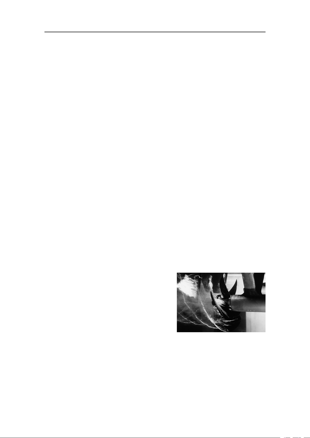
Cavitation
Cavitationistheformationofsmallairbubbles
closetothetransducerface.Thebubblesappear
becausethelocalpressurebecomesnegative
duringpartsoftheacousticpressurecycles.
Thecavitationthresholdincreaseswiththe
hydrostaticpressure.Thenoiseismadewhen
thebubblesimplode.
Cavitationnoisemayappearnearextruding
objectsathigherspeeds,butmoreoftenitis
causedbythepropellers.Propellercavitationisaseveresourceofnoise.Thecavitation
startswhenthewaterowsinthesamedirectionasthepropellerblades.Thisiswhere
thepropellerbladesmovedownwards.
Insomecasesaresonantphenomenonissetupinaholenearthehull.Thissoundwill
haveadiscretefrequency,whileallotherownoisewillhaveawidefrequencyspectrum.
(ImagefromU.S.Navyinthepublicdomain.)
26
401027/B
Preparations
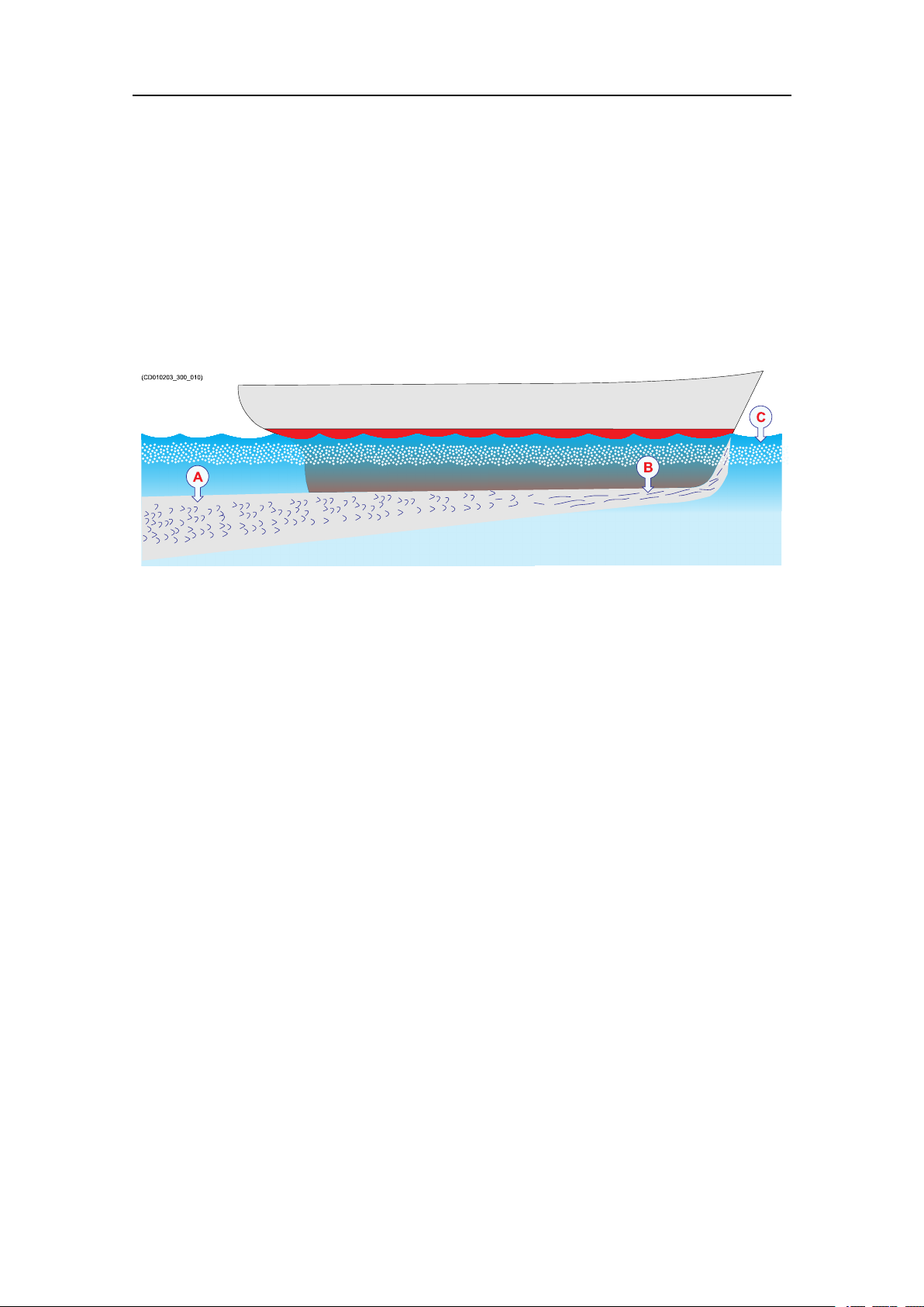
Flownoise
Theupperwaterlayersoftheseacontainamyriadofsmallairbubblescreatedbythe
breakingwaves.Whenthehullmovesthroughwateritwillcauseadisturbance,andthis
willgeneratefriction.Thefrictionzoneiscalledtheowboundarylayer.Theowin
thisboundarylayermaybelaminarorturbulent.
•Thelaminarowisanicelyordered,parallelmovementofthewater.
•Theturbulentowisadisorderlyowpattern,fullofeddies.
ATurbulentow
BLaminarow
CAirbubbles
Airbubblesabsorbandreectthesoundenergy,andtheymayinworstcasesblockthe
soundtransmissionaltogether.
Theboundarylayerincreasesinthicknesswhenitbecomesturbulent.Theboundary
layeristhinintheforwardpartofthevesselhull,andincreasesasitmovesaft.The
thicknessdependsonshipsspeedandontheroughnessofthehull.Allobjectssticking
outfromthehull,ordentsinthehull,willdisturbtheowandwillincreasethethickness
oftheboundarylayer.Whentheowspeedishigh,theturbulencecanbeviolentenough
todestroytheintegrityofthewater.Smallvoidsorcavitiesinthewaterwilloccurand
thisiscalledcavitation.
Rattlenoise
Rattlenoisemaybecausedbylooseobjectsinthevicinityofthetransducer,likexing
bolts.Therattlemayalsocomefromlooseobjectsinsidethehull.
Interference
Interferencefromotherhydroacousticequipmentonboardthesamevesselmaybean
annoyingsourceofdisturbance.Unlessthesamefrequencyisusedformorethanone
pieceofequipmentonlythetransmittedpulsewillcontributetotheinterference.
Inphysics,interferenceisthephenomenoninwhichtwowavessuperposeeach
othertoformaresultantwaveofgreaterorloweramplitude.Interferenceusually
referstotheinteractionofwavesthatarecorrelatedorcoherentwitheachother,
eitherbecausetheycomefromthesamesourceorbecausetheyhavethesameor
401027/B
27

KongsbergEM712Installationmanual
nearlythesamefrequency.Interferenceeffectscanbeobservedwithalltypesof
waves,forexample,light,radio,acoustic,surfacewaterwavesormatterwaves.
https://en.wikipedia.org/wiki/Interference_(wave_propagation),April2016
Ambientnoise
Ambientnoiseisusuallynotalimitingfactortotheperformanceofsonarsandecho
sounders.
Theambientnoisemaybesplitupasfollows:
•Seanoise:Airbubbles,seismicdisturbances,waves,boundaryturbulence,etc.
•Biologicalnoise:Fish,mammals
•Manmadenoise:Othervessels,interference
•Precipitationnoise:Heavyrainorhail
Insomeareas,wheremanyvesselsoperatetogether,theengineandpropellernoisefrom
othervesselsmaybedisturbing.Interferencefromhydroacousticinstrumentslocated
inothervesselsmayalsobealimitingfactor.Theseanoisedependsontheweather
conditions.Inbadweathertheseanoisecanbequitehighduetothewaves.
Electricalselfnoise
Electricalorelectronicselfnoiseispickeduporgeneratedinanyotherpartofthe
equipmentthanthetransducer.
Humpickedupbythetransducercablesorpickedupfromthepowersupplyisusually
themostcommonsourceofelectricalselfnoise.Athigherfrequencies–whererather
widebandwidthsarenecessary–thenoisefromcomponents,transistorsorother
analogueelectronicmaybealimitingfactor.
Somemeanstoreduceacousticnoise
Severalfactorsarecontributingtotheperformanceofthehydroacousticequipment
usedonboardavessel.CarefulplanningoftheEM712installationmayreducethe
acousticnoise.
Unfortunately,itisimpossibletosimplyprovideanumberofspecicproceduresto
reducethenoise.
Animportantfactoristhephysicallocationofthetransducers.Thisdependsonthe
vessel'sdesignandconstruction,howthehullisshaped,andhowthewaterrunsalong
thehull.Otherfactorsdealwithotherequipmentmountedonboard,andthiswillalsobe
vesseldependant.Atmoderateshipspeedsthemachinerynoiseisusuallydominant.At
mediumspeedstheownoiseincreasesmorerapidlyandtakesover,whileathigher
speedthepropellernoisewillbethemaincontributor.
28
401027/B

Preparations
Note
Theinformationheremustbeconsideredasgeneraladvice.EachEM712installation
mustbehandledseparatelydependingonthehulldesignandtheotherelectricaland
mechanicalsystemsinstalledonthevessel.
Reducingownoise
•Theshapeofthetransducer(ordomearoundit)mustbeasstreamlinedaspossible.
•Thehullplatinginfrontofthetransducermustbeassmoothaspossible.
Important
Beespeciallyawareofbilgekeelsandzincalloyanodes.Thekeelmustberoundedoff
withoutsharpedges.Neitherextrudingobjectsnorabrupttransitionsmustbepresent.
Reducingmachinerynoise
•Themainengineandrelevantauxiliaryenginesandequipmentmustbexedtorigid
foundationstoavoidvibrations.
•Anyhullstructurethatmayvibrateshouldbedampedorcoatedtoreducethe
vibrations.
Theuseofshockabsorbersoroatingraftsmaysometimesreducethisnoise.The
structure-bornenoisemaybereducedbyisolation,forexamplebyprovidingvibration
clampingbetweenthetransducerandthehullstructure.
Reducingpropellernoise
•Sufcientclearancebetweenthepropellersandthehull,therudderandthekeelmust
beprovided.
•Placethezincalloyanodesinplaceswherethewaterowistheleastdisturbed.
•Ensurethatthepropellersbladesarecorrectlydesignedandwithoutdamages.
•Theuseofabafebetweenthepropellersandthetransducermayreducenoise
appreciably.
•Staticdischargescausedbytherotatingpropellershaftmayberemovedbyproper
groundingorbymountingacoalbrushfromtheshafttovesselground.
Reducingrattlenoise
Ensurethatnopartsnearthetransducerscanrattleasaresultofwateroworvibrations.
Reducinginterference
Interferencefromthetransmissionpulsesfromotherhydroacousticinstrumentson
boardthevesselisdifculttoavoid.Theproblemmaybereducedbychoosingthe
workingfrequenciescarefullyandtosomeextentbyseparatingthedifferenttransducers.
Onvesselswithalargenumberofseparatehydroacousticsystemsinstalledandin
401027/B
29

KongsbergEM712Installationmanual
simultaneoususe,aseparatesynchronizingsystem(forexampletheK-Sync)should
beconsidered.
Reducingelectricalnoise
•Makesurethatallunitsareproperlygrounded,asthisisimportanttoavoidelectrical
noise.
•Useshieldedcableswithcorrectgrounding.
•SeparateEM712cablesfromothercableswithhighvoltages,largecurrentsor
transients.
•Placeallhighvoltagepowercablesinmetalconduits.
30
401027/B
 Loading...