

Kongsberg EM 2040P Installation Manual
Multibeamechosounder
EM2040P
Installationmanual
417418/B
December2017©KongsbergMaritimeAS

Documentinformation
•Product:KongsbergEM2040P
•Document:Installationmanual
•Documentnumber:417418
•Revision:B
•Dateofissue:December2017
Note
TheinformationcontainedinthisdocumentremainsthesolepropertyofKongsbergMaritimeAS.No
partofthisdocumentmaybecopiedorreproducedinanyformorbyanymeans,andtheinformation
containedwithinitisnottobecommunicatedtoathirdparty,withoutthepriorwrittenconsentof
KongsbergMaritimeAS.
KongsbergMaritimeASendeavourstoensurethatallinformationinthisdocumentiscorrectandfairly
stated,butdoesnotacceptliabilityforanyerrorsoromissions.
Warning
Theequipmenttowhichthismanualappliesmustonlybeusedforthepurposeforwhichitwas
designed.Improperuseormaintenancemaycausedamagetotheequipmentand/orinjurytopersonnel.
Youmustbefamiliarwiththecontentsoftheappropriatemanualsbeforeattemptingtooperate
orworkontheequipment.
KongsbergMaritimedisclaimsanyresponsibilityfordamageorinjurycausedbyimproperinstallation,
useormaintenanceoftheequipment.
Comments
Toassistusinmakingimprovementstotheproductandtothismanual,wewelcomecommentsand
constructivecriticism.
e-mail:km.documentation@km.kongsberg.com
Fortechnicalsupportissues,pleasecontactkm.support@km.kongsberg.com.
Supportinformation
Ifyourequiremaintenanceorrepair,contactyourlocaldealer.Y oucanalsocontactususingthefollowing
address:km.hydrographic.support@kongsberg.com.Ifyouneedinformationaboutourotherproducts,
visithttp://www.km.kongsberg.com
KongsbergMaritimeAS
www.kongsberg.com

Installationmanual
Tableofcontents
ABOUTTHISMANUAL..............................................................7
EM2040P................................................................................9
Systemdescription.............................................................................................................9
Systemdiagram................................................................................................................10
Systemunits.....................................................................................................................11
Transducerdescription...........................................................................................11
ProcessingUnitdescription....................................................................................11
PortableProcessingUnitdescription.....................................................................11
HydrographicWorkStationdescription.................................................................12
RuggedHydrographicW orkStationdescription...................................................12
RemoteControlUnit(K-Rem)description............................................................12
PREPARATIONS.....................................................................14
Personnelqualications...................................................................................................14
Sonarroomrequirements.................................................................................................15
Environmentalrequirements..................................................................................15
Requirementforwatertightintegrity......................................................................15
Sizeandaccessrequirements.................................................................................16
Requirementsforinsulation,heatingandventilation.............................................16
Requirementsforelectricalinstallations,cablesandcommunication...................17
Requirementsforbilgepumpanddecking.............................................................18
Wheretoinstallthetransducer........................................................................................19
Introductiontotransducerlocation.........................................................................19
Mountthetransducerdeep.....................................................................................19
Avoidprotrudingobjectsnearthetransducer.........................................................20
Keepthetransducerfarawayfromthepropellers.................................................21
Chooseatransducerpositionfarawayfromthebowthruster(s)...........................21
Summaryandgeneralrecommendations...............................................................21
Acousticnoise..................................................................................................................23
Contributingfactors................................................................................................23
Selfnoise................................................................................................................24
Ambientnoise.........................................................................................................27
Electricalselfnoise................................................................................................27
Somemeanstoreduceacousticnoise....................................................................27
Vesselcoordinatesystem.................................................................................................29
INSTALLINGTHETRANSDUCER.............................................32
Rulesfortransducerhandling..........................................................................................32
Installationsummary........................................................................................................34
417418/B
3

EM2040P
Installationrequirements..................................................................................................36
Freeviewingsector................................................................................................36
Installationprinciples.......................................................................................................37
Permanenttransducerinstallation..........................................................................37
Nonpermanenttransducerinstallation...................................................................38
Transducerinstallationusingahullunit................................................................39
ReferencepointontheEM2040Ptransducer.................................................................40
Paintingthetransducerface.............................................................................................41
Approvedanti-foulingpaints...........................................................................................43
INSTALLINGTHEEM2040PHARDWAREUNITS.....................44
InstallingtheProcessingUnit..........................................................................................45
InstallingtheProcessingUnit.................................................................................45
ProcessingUnitrearpaneldescription...................................................................47
ProcessingUnitcircuitboardsandmodules..........................................................48
CBMFboard-dipswitchsetting...........................................................................49
InstallingthePortableProcessingUnit............................................................................50
PortableProcessingUnitdescription.....................................................................50
PortableProcessingUnitfrontpaneldescription..................................................51
InstallingtheHydrographicW orkStation.......................................................................52
InstallingtheHydrographicW orkStation..............................................................52
HydrographicWorkStationrearconnectors(MP5810)........................................55
CABLELAYOUTANDINTERCONNECTIONS.............................57
Readthisrst...................................................................................................................58
Cableplans.......................................................................................................................59
ProcessingUnit,singleswath,cableplan..............................................................60
ProcessingUnit,dualswath,cableplan.................................................................61
PortableProcessingUnit,cableplan......................................................................62
Topsidecableplan..................................................................................................63
ListofEM2040Pcables..................................................................................................64
Cabledrawingsandspecications...................................................................................66
RS-232seriallineusingthreewiresandRJ45connector......................................67
RS-422seriallineusingvewiresandRJ45connector........................................68
RS-232seriallineusedforDGNSSinput..............................................................69
RS-422seriallineusedforDGNSSinput..............................................................70
Clocksynchronisation(1PPS)usingacoaxcable.................................................71
Remotecontrol.......................................................................................................72
RemoteControlusingK-Rem................................................................................73
Dummyplugfornotusingremotecontrol.............................................................74
Externalsynchronisation........................................................................................75
Transducercable.....................................................................................................76
4
417418/B

Installationmanual
TransducercableforPortableProcessingUnit......................................................78
Seapathantennainterfacecable-withplug...........................................................80
Antennainterfacecable..........................................................................................82
SeapathMRUinterfacecable.................................................................................83
DCPowercable......................................................................................................84
DRAWINGFILE......................................................................85
Transducerdimensions....................................................................................................86
Transducermountingbracket...........................................................................................87
385422ProcessingUnitdimensions................................................................................88
424178PortableProcessingUnitdimensions.................................................................89
378828HydrographicW orkStationdimensions.............................................................90
370275RemoteControlUnit(K-REM)dimensions.......................................................92
373962RemoteControlUnit(K-REM)wiringdiagram.................................................94
TECHNICALSPECIFICATIONS................................................95
Performancespecications..............................................................................................96
Interfacespecications.....................................................................................................97
Weightsandoutlinedimensions....................................................................................101
Powerrequirements.......................................................................................................102
Environmentalrequirements..........................................................................................104
Alignmentspecications................................................................................................105
EQUIPMENTHANDLING.......................................................107
TransportingKongsbergMaritimeequipment...............................................................108
Liftingunitsandtransportationboxes...........................................................................109
Inspectionofunitsandtransportationboxesafterarrival..............................................111
Specicationsforstoragepriortoinstallationoruse.....................................................112
Unpackinginstructions..................................................................................................114
Unpackingstandardpartsandunits......................................................................114
Unpackingmechanicalunits................................................................................115
Unpackingelectronicandelectromechanicalunits..............................................116
Unpackingtransducers.........................................................................................117
Specicationsforstorageafterunpacking.....................................................................119
GENERALSAFETYRULES.....................................................121
Generalsafetyrules........................................................................................................121
417418/B
5

EM2040P
6
417418/B

Aboutthismanual
Purposeofmanual
Thepurposeofthismanualistoprovidetheinformation,proceduresandbasicdrawings
requiredforthephysicalinstallationoftheEM2040P.
Targetaudience
Aboutthismanual
Themanualisintendedfortechnicalpersonnel;suchasskilledshipyardworkers,
electricians,qualiedengineersandnavalarchitects.Itisassumedthatyouunderstand
thegeneralprinciplesofmaritimeelectronicequipment.Y oumustalsobefamiliarwith
computerhardware,interfacetechnologyandinstallationofelectronicandmechanical
products.
Weassumethatyouarefamiliarwiththebasicacousticprinciplesofsoundinwater.
Wealsoexpectthatyouhavesomeexperiencewithmultibeamand/orsinglebeamecho
soundersinhydrographicapplications..
Installationinstructions
Youmustfollowtheinstructionsinthismanualtoensureoptimalperformance.Asa
guide,installationproceduresarepresentedintheordertheymustbedone.
Theequipmentdescribedinthismanualincludesthecompletesystemwithrelevant
cabinets.Unitsprovidedlocallybythecustomer,installationshipyardorlocal
representativearenotdescribed.
Themanualalsodenestheequipmentresponsibility,andprovidesapplicable
instructionsforunpackingandstorageofunits.
Note
Youmustfollowtheinstructionsgiveninthismanual.Ifnotitmayaffectthewarranty.
KongsbergMaritimeASwillacceptnoresponsibilityforanydamageorinjurytothe
system,vesselorpersonnelcausedbyequipmentthathasbeenincorrectlyinstalledor
maintained,orbydrawings,instructionsorproceduresthathavenotbeenprepared
byus.
Installationdrawings
Theinstallationshipyardmustprovideallnecessaryinstallationdrawings.
417418/B
7

EM2040PInstallationmanual
KongsbergMaritimeASmay,onspecialorder,provideassistancetothesedrawings.
Note
Ifrequired,alldocumentsprovidedbytheshipyardforthephysicalinstallationof
theEM2040Pmustbeapprovedbythevessel’ snationalregistryandcorresponding
maritimeauthorityand/orclassicationsociety.Suchapprovalmustbeobtainedbefore
theinstallationcanbegin.Theshipownerandshipyarddoingtheinstallationare
responsibleforobtainingandpayingforsuchapproval.
TheoutlinedimensionsoftheEM2040PunitsarefoundintheDrawinglechapter
inthismanual.
Onlineinformation
ForinformationabouttheEM2040PandotherproductsfromKongsbergMaritime,
visitourwebsite.
•https://www.km.kongsberg.com
Registeredtrademarks
Observetheregisteredtrademarksthatapply.
Windows
®
isaregisteredtrademarkofMicrosoftCorporationintheUnitedStatesand
othercountries.
®
EM
isaregisteredtrademarkofKongsbergMaritimeASinNorwayandothercountries.
8
417418/B

Topics
Systemdescription,page9
Systemdiagram,page10
EM2040P
EM2040P
Systemunits,page11
Systemdescription
TheEM2040Portableisatruewidebandhighresolutionshallowwatermultibeamecho
sounder.Itisanidealtoolforanyhighresolutionmappingandinspectionapplication.
EM2040PisbasedontheEM2040technology.Thereceiverandtransmitterare
integratedinacommonsonarhead.
Keyfeatures
•Frequencyrangefrom200to400kHz
•Highresolution
•Dualswathoption,allowingsufcientsounddensityalongtrackatreasonablesur-
veyspeed
•FMchirpallowingmuchlongerrangecapability(depthandcoverage)com-
paredtoCWpulses
•Completeroll,pitchandyawstabilization
•Neareldfocusingonbothtransmitandreceive
•Shortpulselengths,largebandwidth.Shortestpulseis14μs
•IHO-S44specialordercompliant
•Seabedimage
•Watercolumnloggingasanoption
•Swathcoverage:140degrees
417418/B
9
EM2040PInstallationmanual
•Beamwidth:1x1degreeat400kHz
•Transducerdepthrating:30metres
•Easytoinstall
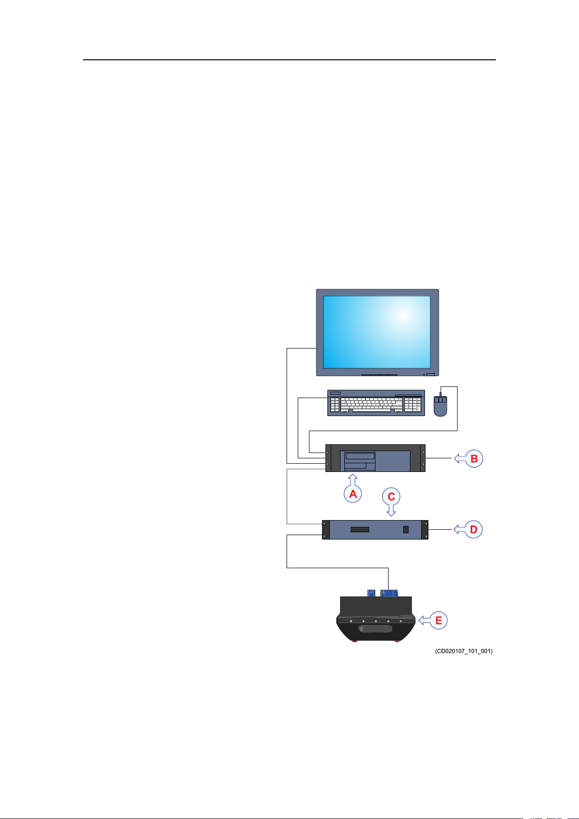
Systemdiagram
ThesystemdiagramidentiesthemaincomponentsofabasicEM2040Psystem.Only
themainconnectionsbetweentheunitsareshown.Detailedinterfacecapabilitiesand
powercablesarenotshown.
AHydrographicW orkStation
BInterfaces:
•Soundspeedsensor
•Tide
•Centredepthoutput
CProcessingUnit
DInterfaces:
•Positioningsystems
•Attitude(roll,pitchand
heave)
•Soundspeedsensor
–WithK-Controller
upgrade
•Velocity
•Heading
•Clock
•Triggerinput/output
•Clocksynchronisation
(1PPS)
ETransducer
10
417418/B
EM2040P
Systemunits
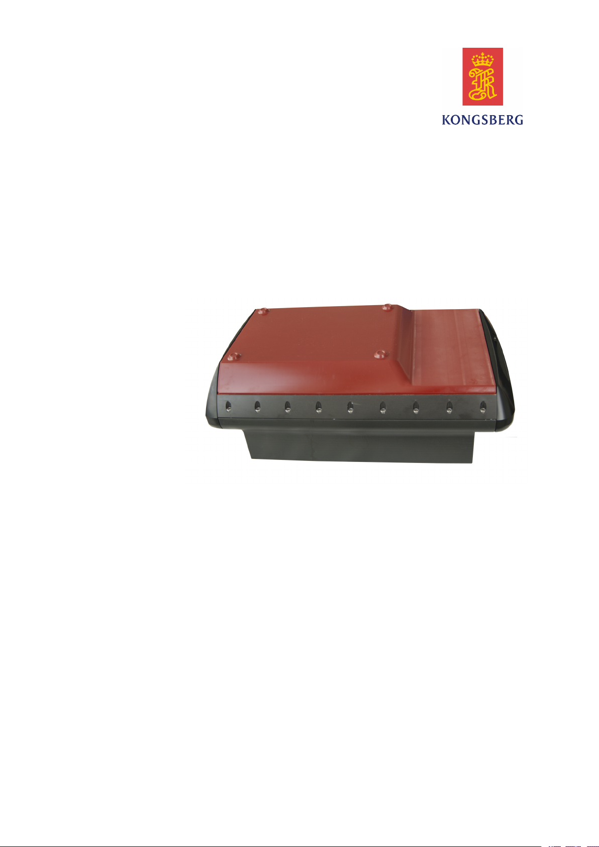
Transducerdescription
Atransducerisadevicethatconvertsoneformofenergytoanother.Inanechosounder
systemthetransducerconvertsbetweenelectricenergyandsound.TheEM2040Phas
transducersfortransmittingandreceivingsoundpulsesinonehousing,andwecallthis
housinga"sonarhead".
Asinglecablewithanunderwaterplug,connectsthe
transducertotheProcessingUnit.
TheEM2040Ptransducerhasseparatelinear
transducerarraysfortransmitandreceiveinaMills
crossconguration.Thetransducercontainsallanalog
electronicsanddigitalcontrolunitswithEthernet
interfacetotheProcessingUnit.Thetransmitteriselectronicallysteerablealongtrack
whilethereceiverissteerableathwartship.
Thetransmittransducerconsistsofthreeseparatelinearrays,onelookingstraightdown
andthetwootherspointing45degreestoeachside.
Thetransducersaremadefromcompositeceramicswhichenablesawidebandwidth.
Thematerialinthepartofthetransducerhousingwhichisexposedtoseawaterishard
anodisedaluminium.
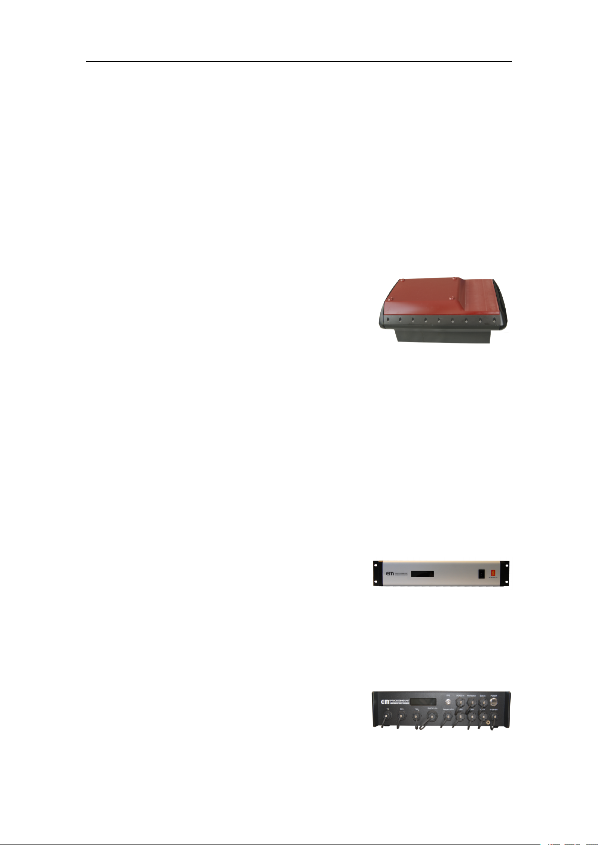
ProcessingUnitdescription
TheProcessingUnitisthecentralcontrollingdeviceintheEMmultibeamsystem.Itis
providedtoprocessthesignalstoandfromthetransducer(s).
Itisanindustrialcomputerwhichisdesignedand
testedforruggeduse.
TheProcessingUnitalsosupplies48Vdcpowertothe
transducer(s).
PortableProcessingUnitdescription
TheEM2040PProcessingUnitisavailableinaportableversion.
Theportableversionhasthesamefunctionalityasthe
standardEMProcessingUnitinarugged,splashproof
enclosure.Italsosupportsasinglecableinterfaceto
theSeapath130Series.
417418/B
11

EM2040PInstallationmanual
HydrographicWorkStationdescription
TheHydrographicWorkStationistheoperatorstationfortheEM2040P.
Adedicatedmaritimecomputerisprovidedwiththe
EM2040PMultibeamechosounder.Itissetupwith
allnecessarysoftware.
TheHydrographicWorkStationisbasedonthe
Microsoft
®
Windowsoperatingsystem.
TheHydrographicWorkStationisnormallymounted
neartheoperatorworkspace.
RuggedHydrographicWorkStationdescription
TheHydrographicWorkStationistheoperatorstationfortheEM2040P.
Adedicatedmaritimecomputerisprovidedwiththe
EM2040PMultibeamechosounder.Itissetupwith
allnecessarysoftware.
TheHydrographicWorkStationisalsoavailablein
asemiruggedorfullyruggedversionforportableuse.
RemoteControlUnit(K-Rem)description
Adedicatedjunctionboxhasbeendesignedtoprovideremoteon/offswitcheswithlight
indicationandinterfacetoaremotesynchronizingsystem.Thejunctionboxcontainsa
terminalblockandfourswitcheswithlampsmountedinthefront.
Note
TheRemoteControlUnitisnotastandardpartof
theEM2040Pdelivery.
TheRemoteControlUnitiscalledK-Rem.Itis
preparedforremotecontrolandinterfacetoanexternal
synchronizationsystemforfourKongsbergechosounders.
•OneSub-bottomproler(SBP120orSBP300)
•TwoEMmultibeamechosounders
•OneEAsinglebeamechosounder
12
417418/B

TheRemoteControlUnitisdesignedtobemountedina19inchrack,butitisalso
possibletomountitonaatsurfaceorinabulkhead.Itisalsopreparedformounting
ontelescopicrails.
EM2040P
417418/B
13

EM2040PInstallationmanual
Topics
Personnelqualications,page14
Sonarroomrequirements,page15
Preparations
Wheretoinstallthetransducer,page19
Acousticnoise,page23
Vesselcoordinatesystem,page29
Personnelqualications
TheinstallationoftheEM2040Pisademandingtask.Itisveryimportantthatthe
personnelinvolvedintheinstallationtasksarecompetentandexperiencedcraftsmen.
Asaminimum,thefollowingcertiedcraftsmenmustbeavailable.
•Navalarchitects
•Welders
•Electricians
•Projectmanager
Note
Thequalityoftheweldingiscriticaltothesafetyofthevessel.W eldingmustonlybe
donebyacertiedwelder .
Ifapplicable,thenalinstallationweldsmustbeapprovedbythevessel’ snational
registry,thecorrespondingmaritimeauthorityand/orclassicationsociety.Observethe
relevantrulesandregulationsrelatedtowelding.
14
417418/B

Sonarroomrequirements
Topics
Environmentalrequirements,page15
Requirementforwatertightintegrity,page15
Sizeandaccessrequirements,page16
Requirementsforinsulation,heatingandventilation,page16
Requirementsforelectricalinstallations,cablesandcommunication,page17
Requirementsforbilgepumpanddecking,page18
Preparations
Environmentalrequirements
TheEM2040Punitsmustbeinstalledinadryanddust-freeenvironment.Theunits
arenotfullyprotectedagainsthumidity ,dustorwater.
Itisimportantthatthesonarroomiskeptdry.TheEM2040Punitsmustnotbeexposed
toexcessivetemperatures,moistureorhumidity.Suchconditionscancausecorrosive
attacksandsubsequentfailurestotheelectroniccircuitry.Visitthesonarroomat
regularintervalstochecktemperatureandhumidity,andtakethenecessaryactions
iftheenvironmentalconditionsarepoor.
ObservetheenvironmentalspecicationsrelatedtotheEM2040Punits.
Requirementforwatertightintegrity
Thesize,locationanddesignofthesonarroommustfullalltherequirementstothe
vessel’swatertightintegrity.
Intheeventofamajorleakinthesonarroom,itmustbepossibletocloseallwatertight
hatchesand/ordoorstothesonarroomtomaintainthevesselstabilityandsafety.
Thephysicalsizeofthesonarroommustbelimited,sothatintheeventofamajor
leak,theoodingofthesonarroomwillnotinduceinstability,orcausethevesselto
capsizeorsink.
Ensurethatallwatertightdecksandbulkheadsareinspectedperiodicallytoverifythat
therearenounprotectedopeningsorimproperpenetrationsthatwillallowprogressive
oodingfromthesonarroom,andthatthewatertightdoorsandhatchesareinplaceand
inworkingorder.
Ensurebilgehighlevelalarmsarearrangedtoprovidetheearliestwarningsofabnormal
accumulation.Thehighlevelbilgealarmsmustbesetaslowaspossibletothedeck
orbilgewellandpositionedalongthecentreareaofthecompartmentorinalocation
atwhichtheuidswillgravitatetorst.
417418/B
15

EM2040PInstallationmanual
Allcablesleadinginandoutofthesonarroommustberuninsteelconduits.Thesesteel
conduitsmustreachupandabovethefreeboarddeck.
Sizeandaccessrequirements
Awelldesignedsonarroomwithawellttedsizeandeasyaccessreducestheriskof
corrosion,andsimpliesmaintenance.Thisincreasessystemreliability.
Note
Thephysicalsizeofthesonarroommustbelimited,sothatintheeventofamajorleak,
theoodingoftheroomwillnotinduceinstability,orcausethevesseltocapsizeorsink.
Thesonarroommustbelargeenoughtohouseallthesystemunits.Theroommust
provideenoughspacetoallowefcientmaintenance.Y oumustbeabletokeepallthe
cabinetdoorsfullyopenwithoutunduerestrictiontoyourmovements.
1Theroommustnotbeusedforanyotherheavymachinery.
2Theroommustnotbeunnecessarilyobstructedbygirders,pipesetc,whichmay
causeinstallationproblemsorimpedemaintenance.
3Theroommustbeaccessibleunderallconditionsatseaorataberth.
4Alldoorsorhatchesmustbedesignedsothatthetoolsandequipmentcanbe
removedwithoutbeingdisassembled.
5Allcablesleadinginandoutofthesonarroommustberuninsteelconduits.These
steelconduitsmustreachupandabovethefreeboarddeck.
Requirementsforinsulation,heatingandventilation
Thebulkheadsinthesonarroommustbeinsulatedandprovidedwithaninteriorwall
tothedeck.Theroommustbeequippedwithheater,anditmustbeconnectedtothe
vessel'sventilationsystem.
Insulationrequirements
Theinsulationinthesonarroomshouldbetheminimumequivalentof50mmof
rock-wool.Pipingpassingthroughthespacepronetocondensationmustbeproperly
insulated.
Heatingrequirements
Heatingisaneffectivemethodforreducinghumidity .Theheaterinthesonarroommust
dimensionedtomaintaintheequipmentwithinitsenvironmentaltolerances.Typical
heatingpowerisminimum1000W .Theheatermustbeinstalledclosetothedeck.
16
417418/B

Preparations
Ventilationrequirements
Thesonarroommustbeconnectedtothevessel'sventilationsystemtoensureasupply
ofcoolingair.Ifaventilationsystemisnotavailable,installtwo3”pipesfromthesonar
roomtoasuitablefreshairlocationondeck.
Thefreshairshouldentertheroomasclosetotheooraspossible,andshouldbe
extractedfromashighaspossible.Afunnelshapeddrip-collectormustbemounted
belowtheventpipestodivertmoisturetothebilge.Onthemaindeck,thebest
ventilationisprovidedwhentheoutletpipeisatleastfourmetershigherthantheinlet
pipe.Tokeepoutseawater,rainandspray,theventilationpipesmustbettedwith
goosenecksoranequivalentdesign.
Note
Ifthevesselislikelytooperateintropicalconditions,asuitableairconditioningsystem
mustbeinstalled.Theairconditioningsystemmustbeabletoprovideanambient
temperaturethatdoesnotexceedthemaximumoperatingtemperaturesoftheEM2040P
unitsthatareinstalledintheroom.
Requirementsforelectricalinstallations,cablesand communication
Theelectricalinstallationsinthesonarroommustmeetminimumrequirementsto
providesuitablelightsandsupplypower.
Lightrequirements
Thesonarroommustbeequippedwithsuitablelightingtosimplifytheinstallation
andtoaidfuturemaintenance.
Communicationrequirements
Thesonarroommustbeequippedwithatelephone,anintercomsystem,oranyother
meansoforalcommunicationbetweenthesonarroomandthebridgeand/orcontrol
room(s).
Powerrequirements
Eachunitinthesonarroomshouldbeprovidedwithaseparatecircuitbreakeronthe
mainssupply.
Aminimumnumberofadditionalelectricaloutletsmustbeprovidedforotherequipment.
Propervesselgroundmustbeprovided.
Cablingrequirements
ThesonarroomunitsareconnectedtootherEM2040Punitslocatedindifferent
compartmentsonthevessel.Theunitsmayalsobeconnectedtoperipheraldevices.If
417418/B
17

EM2040PInstallationmanual
thesecablespassthroughhatchesorareaswheretheymaybedamaged,theymustbe
runinconduits.Minimum2”conduitisrecommended.
Makesurethatallsystemcablesareproperlyconnectedandsecured,andinstalled
withsomeslack.Theslackisessentialtowithstandvibrations,andtofacilitatefuture
maintenanceandreplacements.
Requirementsforbilgepumpanddecking
Ifthesonarroomislocatedbelowthewaterline,itmustbeconnectedtothevessel's
bilgepumpsystem.
Bilgepumprequirement
Ifitisnotpossibletoconnectthesonarroomtothevessel'sbilgepumpsystem,a
separatebilgepumpforthecompartmentmustbeinstalled.
Deckingrequirement
Oncetheinstallationhasbeencompleted,thesonarroommustbesuitablydecked
withoutrestrictingaccesstotheequipmentandthecables.
18
417418/B

Wheretoinstallthetransducer
Topics
Introductiontotransducerlocation,page19
Mountthetransducerdeep,page19
Avoidprotrudingobjectsnearthetransducer,page20
Keepthetransducerfarawayfromthepropellers,page21
Chooseatransducerpositionfarawayfromthebowthruster(s),page21
Summaryandgeneralrecommendations,page21
Preparations
Introductiontotransducerlocation
Asingleanswertothequestion"wheretoinstallthetransducer"cannotbegiven.
Thephysicallocationofthetransducerdependsonthevessel'sdesignandconstruction,
howthehullisshaped,andhowthewaterrunsalongthehull.Therearehowevera
numberofimportantguidelines,andsomeoftheseareevenconicting.
Note
Theinformationheremustbeconsideredasgeneraladvice.EachEM2040Pinstallation
mustbehandledseparatelydependingonthehulldesignandtheotherelectricaland
mechanicalsystemsinstalledonthevessel.
Mountthetransducerdeep
InordertoachievethebestpossibleEM2040Pperformance,mountthetransduceras
deepaspossibleunderthevessel’shull.
Thereareseveralreasonsforthisrecommendation.
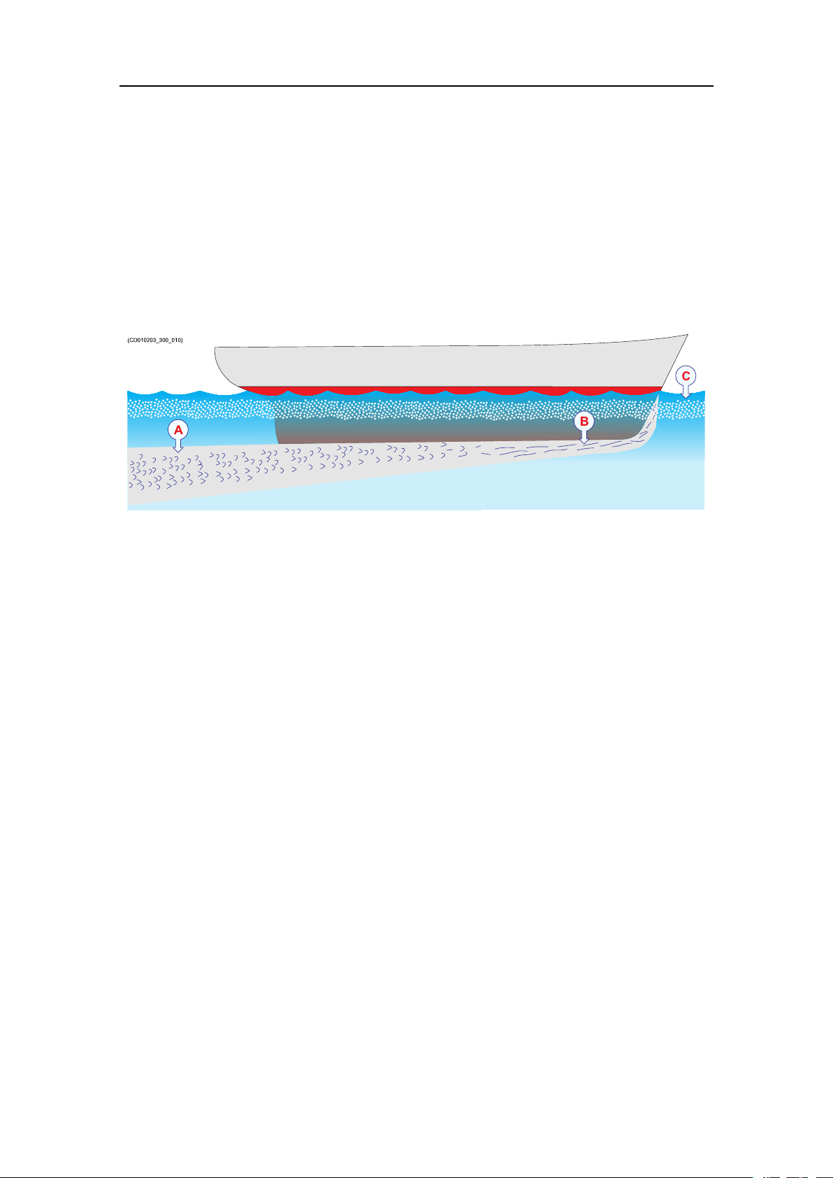
Flownoise
Considerthesituationswhenthevesselisunloaded,andpitchinginheavyseas.The
vesselisridinghigh,andthebowmayevenbeliftedoutofthewater.Thiswillcausea
lotofairtofollowtheshapeofthehull.
Theupperwaterlayersoftheseacontainamyriadofsmallairbubblescreatedbythe
breakingwaves.Inheavyseastheupper5to10metresmaybelledwithair,andthe
highestconcentrationswillbenearthesurface.Airbubblesabsorbandreectthesound
energy,andtheymayinworstcasesblockthesoundtransmissionaltogether.
417418/B
19

EM2040PInstallationmanual
Cavitation
Cavitationistheformationofsmallairbubblesclosetothetransducerface.Thebubbles
appearbecausethelocalpressurebecomesnegativeduringpartsoftheacousticpressure
cycles.Thecavitationthresholdincreaseswiththehydrostaticpressure.Thenoiseis
madewhenthebubblesimplode.
Transmittinginair
Thetransducermustneverbeliftedfreeofthewatersurface.Ifthetransduceris
activatedwhenoutofwateritmaybedamagedbeyondrepair.Mountingthetransducer
atadeeppositiononthehullwillinnormallypreventthis.
Slamming
Slamminghappensifthevesselhullclimbsoutofthewaterinheavyseas.Theforceof
thewaterwhenthehullfallsdownmaypushthetransducerup,andmaycausedamage
bothtothetransducerandtoitsmounting.Thisisespeciallyimportantforlowfrequency
transducerswithlargefaces.Theeffectofslammingcanbereducedbymountingthe
transducerasdeepaspossibleonthehull.
Note
KongsbergMaritimeAStakesnoresponsibilityforanydamagestothetransducer,the
cableorthemountingarrangement,causedbyslamming.
Avoidprotrudingobjectsnearthetransducer
Objectsprotrudingfromthehullwillgenerateturbulenceandownoise.Thiswill
reducetheEM2040Pperformance.
Protrudingobjectsmaybezincanodes,transducersoreventhevessel'skeel.Holesand
pipeoutletsarealsoimportantnoisesources,aswellasroughsurfacescausedbybad
welding.Eventracesofsealingcompound,sharpedges,boltsoremptyboltholeswill
createnoise.Alltheseprotrudingobjectsmayactasresonantcavitiesamplifyingthe
ownoiseatcertainfrequencies.
Donotplaceatransducerinthevicinityofprotrudingobjects,andespeciallynotclose
behindthem.Makesurethatthesurfaceofthetransducerface,thehullplatingandputty
aroundthetransducerisasevenandsmoothaspossible.Mountingscrewsorboltsmust
notbeextrudingfromthetransducer,theinstallationhardwareorthehullplating.If
necessary,grindandpolishallsurfaces.
20
417418/B

Preparations
Keepthetransducerfarawayfromthepropellers
Thepropulsionpropellersisthedominantnoisesourceonmostvessels.Thenoise
iseasilytransmittedthroughthewater.Thisnoisemayoftenreducetheoverall
performanceofyourEM2040P.
Thetransducermustbeinstalledasfarawayfromthepropellersaspossible.Thebest
positionsarethereforeontheforepartofthehull.Positionsoutsidethedirectlineof
sightfromthepropellersarebest.
Onsmallvesselswerecommendmountingthetransduceronthatsideofthekeelwhere
thepropellerbladesmoveupwards.Thisisbecausethepropellercavitationisweakest
onthatside.Thecavitationstartswhenthewaterowsinthesamedirectionasthe
propellerblades.Thisiswherethepropellerbladesmovedownwards.
Chooseatransducerpositionfarawayfromthebow thruster(s)
Bowthrusterpropellersareextremelynoisy.
Wheninoperation,thenoiseandcavitationbubblescreatedbythethrustermaymake
yourEM2040PMultibeamechosounderuseless,almostnomatterwherethetransducer
isinstalled.Whenthebowthrustersarenotinoperation,thetunnelcreatesturbulence.If
yourvesselispitching,thetunnelmaybelledwithairoraeratedwaterintheupper
positionandreleasethisinthelowerposition.
Ingeneral,thetransducershouldthereforebeplacedwellawayfromthebowthruster(s).
However,thisisnotaninvariablerule.Certainthrusterdesigns-combinedwiththeir
physicallocationsonthehull-maystillofferasuitablelocationforthetransducer,even
closetothethruster.Ifyouareindoubt,consultanavalarchitect.
Summaryandgeneralrecommendations
Someoftheinstallationguidelinesprovidedfortransducerlocationmaybeconicting.
Forthisreason,eachvesselmustbetreatedindividuallyinordertondthebest
compromise.
Ingeneral,themostimportantfactoristoavoidairbubblesinfrontofthetransducer
face.Forthisreason,therecommendedtransducerlocationisnormallyintheforepartof
thehull,wellaheadofthenoisecreatedbythebowwave.
Themaximumdistancefromthebowisnormallyequaltoonethirdofthetotalwater
linelengthofthehull.
Ifthevesselhullhasabulbousbow,thismaywellbeagoodtransducerlocation,but
alsointhiscasetheowpatternoftheaeratedwatermustbetakenintoconsideration.
Theforemostpartofthebulbisoftenagoodlocation.
Thisappliestothevesselinnormaltrimandspeed.
417418/B
21

EM2040PInstallationmanual
Important
Thetransducermustneverbetiltedbackwardswhenthevesselismovingatnormal
speed.
Donotplaceatransducerinthevicinityofprotrudingobjects,andespeciallynotclose
behindthem.
Makesurethatthesurfaceoftheresultinginstallationisassmoothandstreamlinedas
possible.
22
417418/B

Preparations
Acousticnoise
Aswithanyotherhydroacousticsystems,thequalityoftheEM2040Pechodataand
presentationsaresubjecttounwantedacousticnoise.Theechoesfromanylargeand
smalltargetmustbedetectedinsidethenoise.
Itisimportantthatwekeepthenoiselevelaslowaspossible.Theisnecessaryto
obtainlongrangeanddependableinterpretationsoftheechoes.Evenwiththeadvanced
noiselteringofferedbytheEM2040P,wemustaddressthenoisechallenge.Thisis
importantduringtheplanningandpreparationsfortheEM2040Pinstallation.
Topics
Contributingfactors,page23
Selfnoise,page24
Ambientnoise,page27
Electricalselfnoise,page27
Somemeanstoreduceacousticnoise,page27
Contributingfactors
Severalfactorsarecontributingtotheperformanceofthehydroacousticequipment
usedonboardavessel.
Suchfactorsinclude:
•Thequalityandpropertiesofthetransmittedsignal
•Thequalityofthereceivingsystem
•Theoperationalsettingsmadeduringoperation
•Thepropertiesofthetarget(s)
•Thesignal-to-noiseratio
Themajorityofthesefactorscanneitherbecontrollednorimprovedbymeans
ofinstallationmethodsortransducerlocations.Thequalityandpropertiesofthe
transmittingandreceivingsystemsarekeyfactorsduringourproductdevelopment,while
ourenduserdocumentationaimstohelptheusertomaketherightltersettingsduring
operation.Asforthetargetproperties,thereisnothinganyofuscandowiththose.
Thesignal-to-noiseratio,however,canbeimprovedbymakingthecorrectchoices
duringinstallation.
Signal-to-noiseratio(oftenabbreviatedSNRorS/N)isameasureusedin
scienceandengineeringthatcomparesthelevelofadesiredsignaltothelevelof
backgroundnoise.Itisdenedastheratioofsignalpowertothenoisepower,often
expressedindecibels.Aratiohigherthan1:1(greaterthan0dB)indicatesmore
417418/B
23

EM2040PInstallationmanual
signalthannoise.WhileSNRiscommonlyquotedforelectricalsignals,itcan
beappliedtoanyformofsignal[...].
http://en.wikipedia.org/wiki/Signal_to_noise_ratio(September2013)
Thesignalistheechothatwewanttoknowsomethingabout,whilethenoiseisany
unwantedsignalsordisturbances.Theechomustbedetectedinthenoiseandthereforeit
isnecessarytokeepthenoiselevelisaslowaspossibleinordertoobtainlongrange
anddependableinterpretation.
Thenoisethatcontributestothesignaltonoiseratiomaybedividedintothefollowing
typesofnoise:
•Selfnoise
•Ambientnoise
•Electricalnoise
•Reverberation
AThetransducercanpickupnoisefrom
•Biologicaldisturbances
•Interference
•Cavitation
•Propellernoise
•Flownoise
•Acousticnoisefromotherhydroacousticsystems
BThetransducercablesarelong,andmaypickupelectricnoisefromgenerators,
pumps,coolingsystemsandotherelectricorelectromechanicaldevices.
CThepreampliersareverysensitive,andtheycaneasilypickupelectricalnoise
frominternalandexternalpowersupplies.Thepreampliersarealsovulnerablefor
analoguenoisecreatedbytheirownelectroniccircuitry.Digitalnoisecreatedby
theconverterandprocessingcircuitrycanalsocreateproblems.
DConverterstransformtheanalogueechoestodigitalformat.
ESignalprocessingcircuitrycancreatedigitalnoise.
Selfnoise
Anyvesselequippedwithahydroacousticsystem(forexampleechosounderorsonar)
willproducemoreorlessselfnoise.
Therearemanysourcesofsuchselfnoise.W ewillheregointosomedetailsinorderto
analysethedifferentsourcesofselfnoiseonavesselandhowtheymayinuenceupon
thenoiselevelofthehydroacousticinstruments.
24
417418/B
Preparations
Machinerynoise
Themaincontributortomachinerynoiseisusuallythemainengineonboardthevessel.
Thecontributionfromauxiliarymachinerymay,however,beconsiderable,especiallyif
itisinpoorshape.Themachinerynoisecanbetransmittedtothetransduceras:
•Structure-bornenoisethroughtheshipstructureandthetransducermountings
•Water-bornenoisethroughthehullintothewatertothetransducer
Electricalnoise
Modernvesselsarenormallyequippedwithalotofelectricinstrumentssuchas
hydroacousticsystems,radars,navigationsystems,andcommunicationequipment.Any
electricinstrumentsmayinsomecauseelectricalinterferenceandnoise.International
regulationsandcerticationsareusedtocontrolandreducethis,buteventheseare
limitediftheelectricalsystemsarepoorlyinstalledand/ormaintained.
Propellernoise
Propellernoiseisoftenthemainsourceofnoiseathighervesselspeeds.Variablepitch
propellersorfastmovingpropellersusuallymakemorenoisethanxedpropellersor
slowmovingpropellers.
Propellernoiseisusuallywater-borne.Insomecases,however,shaftvibrationsor
vibrationsinthehullnearthepropellermaybestructure-bornetothetransducer.Ifa
propellerbladeisdamaged,thismayincreasethenoiseconsiderably.
Propellercavitationisaseveresourceofnoise."Singing"propellersmightbeasourceof
noise,whichinterferesatdiscretefrequencies.Insomecasesstaticdischargefromthe
rotatingpropellershaftmaybequitedisturbing.
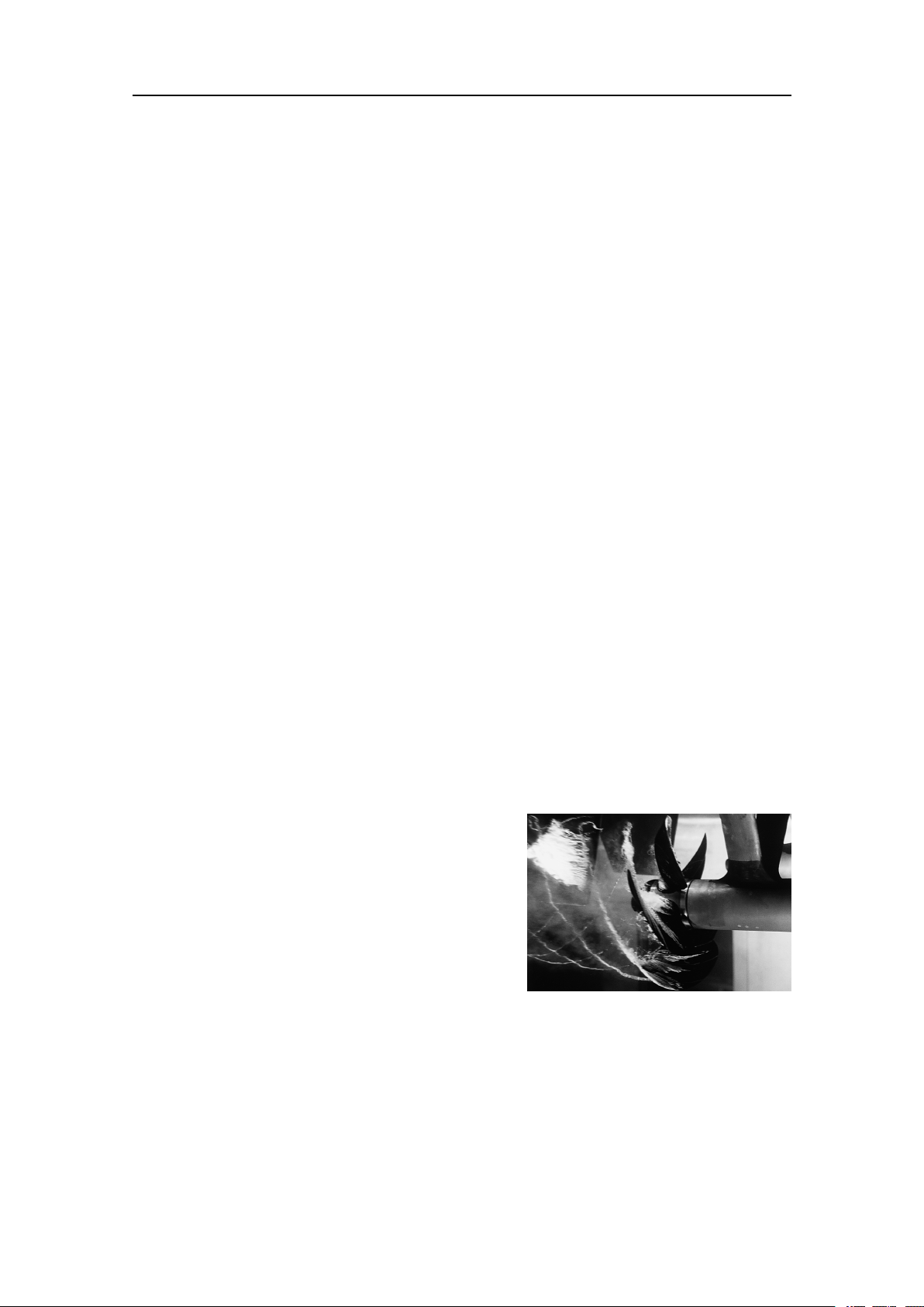
Cavitation
Cavitationistheformationofsmallairbubbles
closetothetransducerface.Thebubblesappear
becausethelocalpressurebecomesnegative
duringpartsoftheacousticpressurecycles.
Thecavitationthresholdincreaseswiththe
hydrostaticpressure.Thenoiseismadewhen
thebubblesimplode.
Cavitationnoisemayappearnearextruding
objectsathigherspeeds,butmoreoftenitis
causedbythepropellers.Propellercavitationisaseveresourceofnoise.Thecavitation
startswhenthewaterowsinthesamedirectionasthepropellerblades.Thisiswhere
thepropellerbladesmovedownwards.
Insomecasesaresonantphenomenonissetupinaholenearthehull.Thissoundwill
haveadiscretefrequency,whileallotherownoisewillhaveawidefrequencyspectrum.
(ImagefromU.S.Navyinthepublicdomain.)
417418/B
25
EM2040PInstallationmanual
Flownoise
Theupperwaterlayersoftheseacontainamyriadofsmallairbubblescreatedbythe
breakingwaves.Whenthehullmovesthroughwateritwillcauseadisturbance,andthis
willgeneratefriction.Thefrictionzoneiscalledtheowboundarylayer.Theowin
thisboundarylayermaybelaminarorturbulent.
•Thelaminarowisanicelyordered,parallelmovementofthewater.
•Theturbulentowisadisorderlyowpattern,fullofeddies.
ATurbulentow
BLaminarow
CAirbubbles
Airbubblesabsorbandreectthesoundenergy,andtheymayinworstcasesblockthe
soundtransmissionaltogether.
Theboundarylayerincreasesinthicknesswhenitbecomesturbulent.Theboundary
layeristhinintheforwardpartofthevesselhull,andincreasesasitmovesaft.The
thicknessdependsonshipsspeedandontheroughnessofthehull.Allobjectssticking
outfromthehull,ordentsinthehull,willdisturbtheowandwillincreasethethickness
oftheboundarylayer.Whentheowspeedishigh,theturbulencecanbeviolentenough
todestroytheintegrityofthewater.Smallvoidsorcavitiesinthewaterwilloccurand
thisiscalledcavitation.
Rattlenoise
Rattlenoisemaybecausedbylooseobjectsinthevicinityofthetransducer,likexing
bolts.Therattlemayalsocomefromlooseobjectsinsidethehull.
Interference
Interferencefromotherhydroacousticequipmentonboardthesamevesselmaybean
annoyingsourceofdisturbance.Unlessthesamefrequencyisusedformorethanone
pieceofequipmentonlythetransmittedpulsewillcontributetotheinterference.
Inphysics,interferenceisthephenomenoninwhichtwowavessuperposeeach
othertoformaresultantwaveofgreaterorloweramplitude.Interferenceusually
referstotheinteractionofwavesthatarecorrelatedorcoherentwitheachother,
eitherbecausetheycomefromthesamesourceorbecausetheyhavethesameor
26
417418/B

nearlythesamefrequency.Interferenceeffectscanbeobservedwithalltypesof
waves,forexample,light,radio,acoustic,surfacewaterwavesormatterwaves.
https://en.wikipedia.org/wiki/Interference_(wave_propagation),April2016
Ambientnoise
Ambientnoiseisusuallynotalimitingfactortotheperformanceofsonarsandecho
sounders.
Theambientnoisemaybesplitupasfollows:
•Seanoise:Airbubbles,seismicdisturbances,waves,boundaryturbulence,etc.
•Biologicalnoise:Fish,mammals
•Manmadenoise:Othervessels,interference
•Precipitationnoise:Heavyrainorhail
Preparations
Insomeareas,wheremanyvesselsoperatetogether,theengineandpropellernoisefrom
othervesselsmaybedisturbing.Interferencefromhydroacousticinstrumentslocated
inothervesselsmayalsobealimitingfactor.Theseanoisedependsontheweather
conditions.Inbadweathertheseanoisecanbequitehighduetothewaves.
Electricalselfnoise
Electricalorelectronicselfnoiseispickeduporgeneratedinanyotherpartofthe
equipmentthanthetransducer.
Humpickedupbythetransducercablesorpickedupfromthepowersupplyisusually
themostcommonsourceofelectricalselfnoise.Athigherfrequencies–whererather
widebandwidthsarenecessary–thenoisefromcomponents,transistorsorother
analogueelectronicmaybealimitingfactor.
Somemeanstoreduceacousticnoise
Severalfactorsarecontributingtotheperformanceofthehydroacousticequipment
usedonboardavessel.CarefulplanningoftheEM2040Pinstallationmayreduce
theacousticnoise.
Unfortunately,itisimpossibletosimplyprovideanumberofspecicproceduresto
reducethenoise.
Animportantfactoristhephysicallocationofthetransducers.Thisdependsonthe
vessel'sdesignandconstruction,howthehullisshaped,andhowthewaterrunsalong
thehull.Otherfactorsdealwithotherequipmentmountedonboard,andthiswillalsobe
vesseldependant.Atmoderateshipspeedsthemachinerynoiseisusuallydominant.At
mediumspeedstheownoiseincreasesmorerapidlyandtakesover,whileathigher
speedthepropellernoisewillbethemaincontributor.
417418/B
27

EM2040PInstallationmanual
Note
Theinformationheremustbeconsideredasgeneraladvice.EachEM2040Pinstallation
mustbehandledseparatelydependingonthehulldesignandtheotherelectricaland
mechanicalsystemsinstalledonthevessel.
Reducingownoise
•Theshapeofthetransducer(ordomearoundit)mustbeasstreamlinedaspossible.
•Thehullplatinginfrontofthetransducermustbeassmoothaspossible.
Important
Beespeciallyawareofbilgekeelsandzincalloyanodes.Thekeelmustberoundedoff
withoutsharpedges.Neitherextrudingobjectsnorabrupttransitionsmustbepresent.
Reducingmachinerynoise
•Themainengineandrelevantauxiliaryenginesandequipmentmustbexedtorigid
foundationstoavoidvibrations.
•Anyhullstructurethatmayvibrateshouldbedampedorcoatedtoreducethe
vibrations.
Theuseofshockabsorbersoroatingraftsmaysometimesreducethisnoise.The
structure-bornenoisemaybereducedbyisolation,forexamplebyprovidingvibration
clampingbetweenthetransducerandthehullstructure.
Reducingpropellernoise
•Sufcientclearancebetweenthepropellersandthehull,therudderandthekeelmust
beprovided.
•Placethezincalloyanodesinplaceswherethewaterowistheleastdisturbed.
•Ensurethatthepropellersbladesarecorrectlydesignedandwithoutdamages.
•Theuseofabafebetweenthepropellersandthetransducermayreducenoise
appreciably.
•Staticdischargescausedbytherotatingpropellershaftmayberemovedbyproper
groundingorbymountingacoalbrushfromtheshafttovesselground.
Reducingrattlenoise
Ensurethatnopartsnearthetransducerscanrattleasaresultofwateroworvibrations.
Reducinginterference
Interferencefromthetransmissionpulsesfromotherhydroacousticinstrumentson
boardthevesselisdifculttoavoid.Theproblemmaybereducedbychoosingthe
workingfrequenciescarefullyandtosomeextentbyseparatingthedifferenttransducers.
Onvesselswithalargenumberofseparatehydroacousticsystemsinstalledandin
28
417418/B
Preparations
simultaneoususe,aseparatesynchronizingsystem(forexampletheK-Sync)should
beconsidered.
Reducingelectricalnoise
•Makesurethatallunitsareproperlygrounded,asthisisimportanttoavoidelectrical
noise.
•Useshieldedcableswithcorrectgrounding.
•SeparateEM2040Pcablesfromothercableswithhighvoltages,largecurrentsor
transients.
•Placeallhighvoltagepowercablesinmetalconduits.
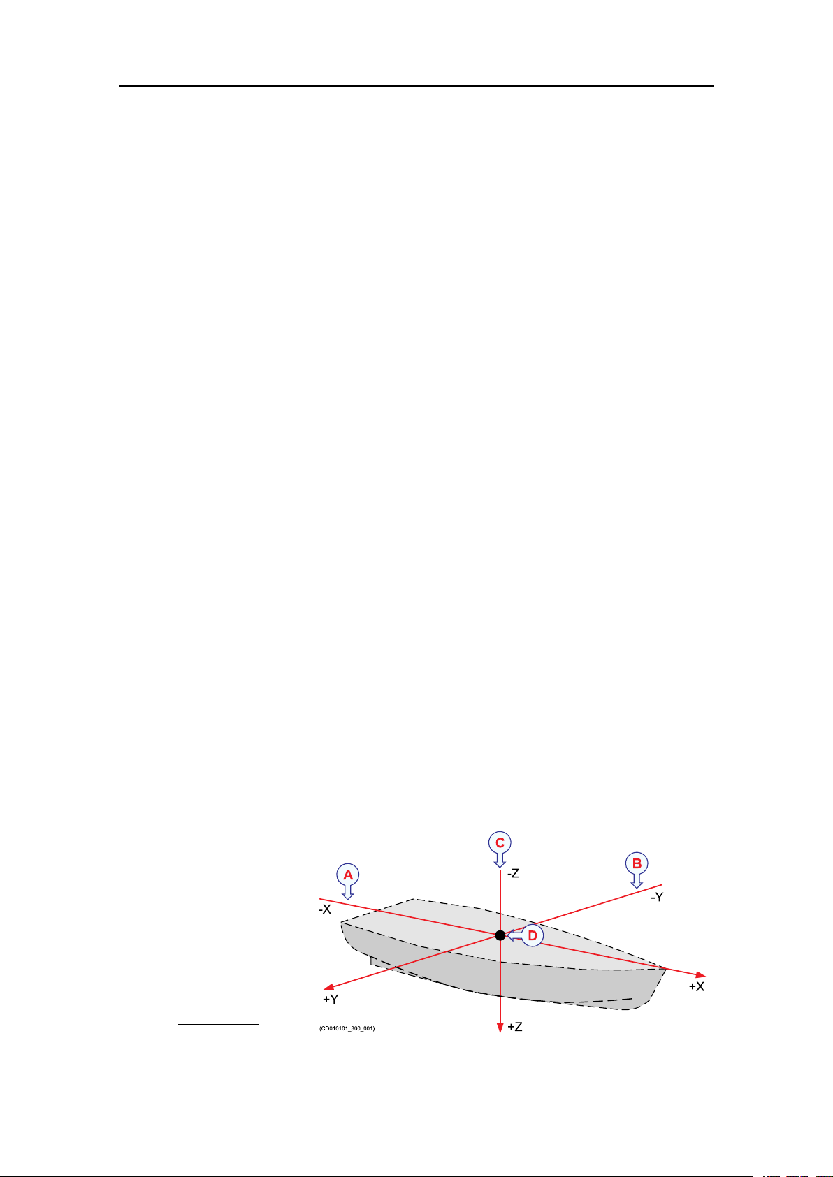
Vesselcoordinatesystem
Thevesselcoordinatesystemisestablishedtodenetherelativephysicallocations
ofsystemsandsensors.
Whenyouhaveseveraldifferentsensorsandtransducersonyourvessel,andyouwish
eachofthemtoprovideaccuratedata,youneedtoknowtheirrelativephysicalpositions.
Theantennaofapositionsensoristypicallymountedhighabovethesuperstructure,
whileamotionsensorislocatedclosetothevessel’scentreofgravity.Bothofthese
arephysicallypositionedfarawayfromthetransduceronadepthsensor,whichmaybe
locatedclosertothebow.
Veryoften,theinformationfromonesensordependsondatafromanother.Itisthen
importantthattherelevantmeasurementsarecompensatedfortheserelativedistances.
Example
Ifyouwishtomeasuretheactualwaterdepth,youwillneedtoknowthe
verticaldistancefromtheechosoundertransducertothewaterline.Since
thevessel’sdisplacementchangeswiththeamountofcargo,fueletc,the
physicallocationofthewaterlineonthehullmusteitherbemeasuredata
regularbasis,ormeasuredwithasecondsensor.
Inordertoestablish
asystemtomeasure
therelativedistance
betweensensors,a
virtualcoordinatesystem
isestablished.This
coordinatesystemuses
threevectors;X,YandZ.
ATheX-axisis
thelongitudinal
directionofthe
vessel,andin
417418/B
29

EM2040PInstallationmanual
parallelwiththedeck.ApositivevalueforXmeansthatasensororareference
pointislocatedaheadofthereferencepoint(origin).
BTheY-axisisthetransverse
directionofthevessel,andinparallelwiththedeck.
ApositivevalueforYmeansthatasensororareferencepointislocatedonthe
starboard
CTheZ-axisisvertical
thatasensororanewreferencepointislocatedunder
DReferencepoint(origin)
sideofthereferencepoint(origin).
,andinparallelwiththemast.ApositivevalueforZmeans
thereferencepoint(origin).
Coordinatesystemorigin
Theoriginisthecommonreferencepointwhereallthreeaxisinthevesselcoordinate
systemmeet.Allphysicallocationsofthevessel’ssensors(radarandpositioningsystem
antennas,echosounderandsonartransducers,motionreferenceunitsetc)arereferenced
totheorigin.Inmostcases,thelocationofthevessel’s"ofcial"originhasbeendened
bythedesignerorshipyard.Thisoriginisnormallyidentiedwithaphysicalmarking,
andalsoshownonthevesseldrawings.
Frequentlyusedlocationsare:
•Aftimmediatelyovertherudder(frame0)
•Vessel’scentreofgravity
•Thephysicallocationofthemotionreferenceunit(MRU)
Coordinatesystemalternativeorigins
Ifnecessary,otheroriginlocationsmaybedenedforspecicproductsorpurposes.One
exampleistheNavigationReferencePointthatisfrequentlyused.Wheneveravessel
issurveyedtoestablishaccurateoffsetinformation,thesurveyormayalsoestablishan
alternativeoriginlocation.Wheneverrelevant,anysuchalternativelocationsmust
bedenedusingoffsetvaluestothe"ofcial"originestablishedbythedesigneror
shipyard.Acommonlyusedalternativeoriginisthephysicallocationofthevessel’s
motionreferenceunit(MRU).
Deningthephysicallocationofeachsensor
Bymeansofthevesselcoordinatesystem,thephysicallocationofeverysensorcan
bedenedusingthreenumericalvaluesforX,YandZ.Thesevaluesmustdenethe
verticalandhorizontaldistancesfromasinglereferencepoint;theorigin.Thephysical
locationofthemotionreferenceunit(MRU)isoftenthemostimportantsensortodene.
Formanysystems,thevesselheadingisalsoacriticalmeasurement.
30
417418/B
 Loading...