

Kongsberg DPS 232 Installation Manual
Installation manual
DPS 232
Differential Positioning System


KongsbergDPS232
DifferentialPositioningSystem
InstallationManual
December2012
G210-14/3.0
©
KongsbergSeatexAS

Documenthistory
Documentnumber:G210-14
Rev.3.0
December2012Updatedforproductrelease1.01.00.
Copyright
©2012KongsbergSeatexAS
Allrightsreserved.Nopartofthisworkcoveredbythecopyrighthereonmaybereproducedorotherwise
copiedwithoutpriorpermissionfromKongsbergSeatexAS.
Disclaimer
Theinformationcontainedinthisdocumentissubjecttochangewithoutpriornotice.KongsbergSeatex
ASshallnotbeliableforerrorscontainedhereinorforincidentalorconsequentialdamagesinconnection
withthefurnishing,performance,oruseofthisdocument.
KongsbergSeatexASendeavourstoensurethatallinformationinthisdocumentiscorrectandfairly
stated,butdoesnotacceptliabilityforanyerrorsoromissions.
Warning
Theequipmenttowhichthismanualappliesmustonlybeusedforthepurposeforwhichitwas
designed.Improperuseormaintenancemaycausedamagetotheequipmentand/orinjurytopersonnel.
Theusermustbefamiliarwiththecontentsoftheappropriatemanualsbeforeattemptingtooperate
orworkontheequipment.
KongsbergSeatexASdisclaimsanyresponsibilityfordamageorinjurycausedbyimproperinstallation,
useormaintenanceoftheequipment.
Comments
Toassistusinmakingimprovementstotheproductandtothismanual,wewelcomecommentsand
constructivecriticism.
e-mail:km.seatex@kongsberg.com
KongsbergSeatexAS
www.kongsberg.com

InstallationManual
Tableofcontents
Glossary..................................................................................................................8
1INTRODUCTION.............................................................13
1.1Aboutthereader...................................................................................................13
1.2Notationsusedinthismanual...............................................................................13
1.3Productrestrictions...............................................................................................14
1.3.1Restrictionsinguarantee..........................................................................14
1.3.2Restrictionsinuse...................................................................................14
1.3.3ECDISdisclaimer....................................................................................14
1.4Disposal................................................................................................................15
1.5Equipmenthandling..............................................................................................15
2PRODUCTDESCRIPTION................................................16
2.1Purposeandapplications......................................................................................16
2.2Systemcomponents..............................................................................................16
3TECHNICALSPECIFICATIONS........................................19
3.1Performancedata..................................................................................................19
3.1.1DPS232system.......................................................................................19
3.2Physicaldimensions.............................................................................................19
3.2.1ProcessingUnit........................................................................................19
3.2.2GNSSantenna.........................................................................................20
3.2.3IALAbeaconantenna...............................................................................20
3.2.46Ucabinet..............................................................................................20
3.2.512Ucabinet............................................................................................20
3.3Power....................................................................................................................21
3.3.1ProcessingUnit........................................................................................21
3.3.2GNSSantenna.........................................................................................21
3.3.3IALAbeaconantenna...............................................................................21
3.4Environmentalspecications................................................................................21
3.4.1ProcessingUnit........................................................................................21
3.4.2GNSSantenna.........................................................................................22
3.4.3IALAbeaconantenna...............................................................................22
3.5Externalinterfaces................................................................................................22
3.5.1ProcessingUnit........................................................................................22
3.6Productsafety.......................................................................................................22
3.6.1ProcessingUnit........................................................................................22
3.7Radiofrequencies.................................................................................................23
3.7.1GNSSantenna.........................................................................................23
3.7.2GNSSreceiver.........................................................................................23
3.7.3IALAbeaconreceiver..............................................................................23
G210-14/3.0
3

KongsbergDPS232
3.8Dataoutputs..........................................................................................................23
3.8.1ProcessingUnit........................................................................................23
3.9Datainputs............................................................................................................24
3.9.1ProcessingUnit........................................................................................24
3.10Datums..................................................................................................................24
3.10.1ProcessingUnit........................................................................................24
3.11Compasssafedistance..........................................................................................24
3.11.1ProcessingUnit........................................................................................24
3.12InterfacesProcessingUnit....................................................................................25
3.12.1InterfacesProcessingUnitfront................................................................25
3.12.2InterfacesProcessingUnitrear..................................................................25
3.12.3RS-422AandBsignaldenition..............................................................27
3.12.4COM1andCOM2..................................................................................28
3.12.5Connectorboard......................................................................................28
3.12.6Ethernetconnection..................................................................................30
3.13LEDindicatorsProcessingUnit...........................................................................32
3.13.1LEDindications.......................................................................................32
4INSTALLATION..............................................................33
4.1Logistics...............................................................................................................33
4.2Locationofsystemparts.......................................................................................34
4.2.1GNSSantenna.........................................................................................34
4.2.2IALAbeaconantenna...............................................................................36
4.2.3ProcessingUnit........................................................................................36
4.3Cabinetinstallation...............................................................................................37
4.3.1Installationwithdeliveredcabinet.............................................................37
4.3.2Installationwithoutdeliveredcabinet........................................................37
4.4Coaxconnectorinstallation..................................................................................38
4.5Antennaandcableinstallation..............................................................................42
4.5.1GNSSantennaandcableinstallation.........................................................43
4.5.2IALAbeaconantennaandcableinstallation..............................................44
4.6Electricalinstallation............................................................................................45
5CONFIGURATION...........................................................47
5.1Startingthesystem...............................................................................................47
5.2Systemmodes.......................................................................................................47
5.3StandardNAVEngineconguration....................................................................48
5.4Vesselconguration..............................................................................................50
5.4.1Vesselgeometry.......................................................................................50
5.4.2Vesselshapefromle...............................................................................52
5.4.3Vesseldescription....................................................................................55
5.4.4Vesselequipment.....................................................................................55
5.5Sensorsconguration...........................................................................................56
4
G210-14/3.0

InstallationManual
5.5.1GNSSgeometry.......................................................................................56
5.5.2GNSSprocessing.....................................................................................57
5.5.3SBAStracking.........................................................................................58
5.5.4HP/XP/G2..............................................................................................58
5.5.5IALA......................................................................................................59
5.5.6RTK........................................................................................................59
5.6Monitoringpointsconguration...........................................................................59
5.7Communicationinterfaceconguration...............................................................63
5.7.1Input/output.............................................................................................63
5.7.2Congurationdetails................................................................................64
5.7.3Telegramoutputinterface.........................................................................66
5.7.4Telegramtimingproperties.......................................................................68
5.7.5Gyrointerface..........................................................................................69
5.7.6DPinterface.............................................................................................70
5.7.7DGNSSlink............................................................................................70
5.7.8DGPS464conguration...........................................................................71
5.7.9Serialportextender.................................................................................72
5.7.10Datapool.................................................................................................72
5.8AISinterface........................................................................................................73
5.9Soundalarms.......................................................................................................74
5.10Mapdata..............................................................................................................74
5.10.1C-Mapsupport.........................................................................................74
5.10.2Updatedatabase.......................................................................................75
5.10.3Updatelicense.........................................................................................76
5.11CopyCongurationtool.......................................................................................76
5.12RestoreCongurationtool...................................................................................77
6COMMISSIONING..........................................................79
6.1SystemVericationtool......................................................................................79
6.2Copyloggeddata..................................................................................................80
7SYSTEMBACKUPANDRESTORE.....................................81
7.1Updateorcreatebackupstick...............................................................................81
7.2Restorefromdiskbasedbackup...........................................................................82
7.3Restorefrombackupstick....................................................................................83
7.4CreatebackupstickonaPC.................................................................................85
8MECHANICALDRAWINGS..............................................86
8.1ProcessingUnitmechanicaldimensions..............................................................87
8.26Ucabinetdimensions........................................................................................88
8.312Ucabinetdimensions......................................................................................89
8.4GNSSantennamechanicaldrawing.....................................................................90
8.5GNSSantennainstallation....................................................................................91
8.6IALAantennamechanicaldrawingandinstallation............................................92
G210-14/3.0
5

KongsbergDPS232
9PARTSLIST...................................................................94
9.1Standardcomponents............................................................................................94
9.2Systemaccessories...............................................................................................94
10REFERENCES..................................................................96
AOUTPUTTELEGRAMS.....................................................97
A.1ABBDPmessages.................................................................................................97
A.2ARABBmessages................................................................................................98
A.3DPGGAmessages................................................................................................99
A.4DTMmessages...................................................................................................100
A.5GBSmessages....................................................................................................100
A.6GGAmessages...................................................................................................101
A.7GLLmessages....................................................................................................102
A.8GNSmessages....................................................................................................103
A.9GRSmessages....................................................................................................104
A.10GSAmessages....................................................................................................104
A.11GSTmessages....................................................................................................105
A.12GSVmessages....................................................................................................105
A.13RMCmessages...................................................................................................106
A.14VBWmessages...................................................................................................107
A.15VTGmessages....................................................................................................107
A.16ZDAmessages....................................................................................................108
BOPTIONALIALABEACONANTENNA.............................109
C½"COAXCABLESPECIFICATIONS..............................111
DG_03212–01COAXCABLESPECIFICATIONS...............112
ESERIALPORTEXTENDER.............................................114
E.1Mechanicalinstallation.......................................................................................115
E.2Electricalinstallation..........................................................................................115
E.3Conguration......................................................................................................115
FNMEADISPLAY............................................................117
F.1Physicaldimensions...........................................................................................117
F.2Power..................................................................................................................118
F.3Environmentalspecications..............................................................................118
F.4NMEAtelegraminput........................................................................................118
F.5Installation..........................................................................................................118
F.6Cableandconnectors..........................................................................................119
F.7ConnectionwithDPSsystem.............................................................................120
F.8Operation............................................................................................................120
F.9Displayscreens...................................................................................................121
GOLDDGPS464RADIO.................................................122
6
G210-14/3.0

InstallationManual
G.1Technicaldata.....................................................................................................122
G.1.1Physicaldimensions...............................................................................122
G.1.2Environmentalspecications..................................................................123
G.1.3Radiofrequencies..................................................................................123
G.2LEDindicators....................................................................................................123
G.3Externalinputandoutput...................................................................................124
G.4Conguration......................................................................................................125
G.5UHFantennaspecications................................................................................127
HDGPS464RADIO.........................................................129
H.1Technicaldata.....................................................................................................129
H.1.1Physicaldimensions...............................................................................129
H.1.2Environmentalspecications..................................................................130
H.2LEDindicators....................................................................................................130
H.3Externalinputandoutput...................................................................................131
H.4Conguration......................................................................................................132
H.4.1Menudescription...................................................................................133
H.4.2Loaddefaultconguration......................................................................137
H.4.3Frequencylist........................................................................................138
IROVSUPPORT.............................................................140
I.1CongureAPOS.................................................................................................140
I.2CongureROVinOperatorsoftwaresettings...................................................142
JFREEANDOPENSOURCESOFTWARE...........................145
J.1TinyLoginlicense...............................................................................................145
G210-14/3.0
7

KongsbergDPS232
Glossary
Abbreviations
AISAutomaticIdenticationSystem
APAftPerpendicular.Theverticalintersectionofthedesignwaterline
atthestern,alternativelythecenterlineoftherudderstock.
APOSAcousticPositionOperatorStation
BLBaseLine.Isthesameasthekeelforavesselwithhorizontal
keelline.
BTBearingtotarget
C/ACourse/acquisition
CATCustomeracceptancetest
CEPCircularerrorprobability
CFCompactFlashdisk
CGCentreofGravity.Themasscentreofavessel.Thisisnormally
thelocationwithleastlinearacceleration,andhencethebest
locationformeasurementsofrollandpitch.
CLCentreline.Isthelongitudinalaxisalongthecentreoftheship.
COGCourseoverground
CPUCentralprocessingunit
CRPCommonReferencePoint.
CTPCommissioningtestprocedure
DCWDigitalchartoftheworld
DGLONASSDifferentialGLONASS
DGNSSDifferentialGlobalNavigationSatelliteSystem
DGPSDifferentialGPS
DNVDetNorskeVeritas
DOPDilutionofpositioning
DPDynamicpositioning
DPODPoperator
DPSDifferentialpositioningsystem
DQIDifferentialGPSqualityindicator
DRMSDistancerootmeansquare
DTDistancetotarget
DWLDesignwaterline
EBLElectronicbearingline
8
G210-14/3.0

ECDISElectronicchartdisplayandinformationsystem
ECEFEarthcentreearthxed
ECSElectronicchartsystem
ED50EuropeanDatumof1950
EGNOSEuropeanGeostationaryNavigationOverlaySystem
EMCElectromagneticcompatibility
EMIElectromagneticinterference
ENEuropeanNorm
EPEEstimatedpositionerror
ETAEstimatedtimeofarrival
ETEEstimatedtimeenroute
FPForwardperpendicular
GLONASSGlobalnavigationsatellitesystem
InstallationManual
GNSSGlobalnavigationsatellitesystem
GPSGlobalpositioningsystem
GUIGraphicaluserinterface
HDGThevessel'sheadingrelativetoNorth.Positiveclockwise.
HDOPHorizontaldilutionofprecision
HMIHumanmachineinterface
HPHighprecision
HWPHardwareplatform
IALAInternationalAssociationofLighthouseAuthorities
IECInternationalElectrotechnicalCommittee
IMOInternationalMaritimeOrganization
IMUInertialMeasurementUnit
IPIngressprotection
LEDLightemittingdiode
LGNDLogicground
LOALengthoverall
LPPLengthbetweenperpendiculars
MMSIMaritimeMobileServiceIdentity
MOPMotionObservationPoints
MPMonitoringPoint
MSASMultifunctionaltransportsatellite-basedaugmentationsystem
NANotapplicable
NAD27NorthAmericandatumof1927
G210-14/3.0
9

KongsbergDPS232
NDSNotdetectedserialport
NMEANationalMarineElectronicsAssociation.NMEA0183isa
standardforinterchangeofinformationbetweennavigation
equipment.
NRPNavigationReferencePoint,i.e.thereferencepointforall
measurementsinthissystem.Forthissystem,thisisidenticalto
theGNSSantennapoint.
PGNDPowerground
PPSPulsepersecond
PRNPseudorandomnoise
PSSPhysicalshorestation
QAQualityassurance
RAIMReceiverautonomousintegritymonitoring
RFIRadiofrequencyinterface
RMSRootmeansquare
ROVRemotelyOperatedVehicle
RTCMRadioTechnicalCommissionofMaritimeServices
SASelectiveavailability
SBASSatelliteBasedAugmentationSystem
SLSpeedalongship
SBRSystemBackupandRestore
SNRSignal/noiseratio
SOGSpeedoverground
SPSStandardpositioningservice
STSpeedtransverseship
SWSoftware
TMVTargetmonitoringview
TTGTimetogo
UDPUserDatagramProtocol
UPSUninterruptablepowersupplyusedtoensurepowersupplyin
caseofmainsinterruption.
UTCUniversalTimeCoordinated.Thisistheofcialtimeintheworld
andhasreplacedGMT(GreenwichMeanTime)astheofcial
time.
UTMUniversaltransversemercator
WAASWideareaaugmentationsystem
WEEEWasteelectricalandelectronicequipment
10
G210-14/3.0

InstallationManual
WGS84WorldGeodeticSystemof1984
Denitions
BackupstickAbootableUSBmemorystickwithafullyoperationalWindows
imageandsoftwaretocreate,updateandinstallawindowsimage.
GPStimeThetimeintheGPSsystem.TheGPStimeiswithinUTCtime
±180nsec(95percent)plusleapsecond.
HostsystemInthismanualdenedasNavigationcomputers,Dynamic
PositioningSystemsetc,receivingdatafromthissystem.
OriginThezeropointinthecoordinatesystem.Theoriginlocationcan
beconguredbytheuser.TypicaloriginlocationsareCRPina
surveyreport,CG,MRUortheintersectionpointbetweenAP,
BLandCL.
StarboardWhenlookinginthebowdirectionofavehicle,thisistheright
handsideofthevehicle.
G210-14/3.0
11

KongsbergDPS232
12
G210-14/3.0

1Introduction
1.1Aboutthereader
Thisinstallationmanualisintendedasareferencemanualforthepersonnelinstalling
thesystemanditcontainsthenecessaryinformationtoinstallandsetuptheDPS
equipmentonavessel.
Introduction
1.2Notationsusedinthismanual
Thefollowingnotationsareusedinthismanual:
Boldtextisusedforallmenunames.AseriesofmenuselectionsisindicatedbyFile→
New
Italicsisusedformanualnamesandforinformationthatneedsyourattention.
Note
Anoteisusedtodrawattentiontospecialfeaturesorbehaviouroftheequipment.
Caution
Cautionisusedtomaketheuserawareofproceduresandoperational
practicewhich,ifnotfollowed,mayresultindegradedperformanceor
damagetotheequipment.
WARNING
Warningisusedwhenitisnecessarytowarnpersonnelthatriskof
injuryordeathexistsifcareisnotexercised.
G210-14/3.0
13

KongsbergDPS232
1.3Productrestrictions
1.3.1Restrictionsinguarantee
ChangesormodicationstotheproductnotexplicitlyapprovedbyKongsbergSeatex
ASwillvoidtheguarantee.
TheliabilityofKongsbergSeatexASislimitedtorepairofthissystemonlyunderthe
giventermsandconditionsstatedinthesalesdocuments.Consequentialdamagessuch
ascustomer'slossofprotordamagetoothersystemstraceablebacktothissystem's
malfunctions,areexcluded.Thewarrantydoesnotcovermalfunctionsofthesystem
resultingfromthefollowingconditions:
•Over-voltageorincorrectpowerconnection.
•ShortingofGNSSantennacableduringoperationofthesystems.
1.3.2Restrictionsinuse
TheDPSfunctionisbasedonGNSSsignalsandrequiresfreesighttothesky,minimum
fourvisiblesatellites,PDOPvaluelessthan6andotherwisenormalconditionstooperate.
1.3.3ECDISdisclaimer
ThissystemisnotanECDISsystem,hencetypeapprovalaccordingtoIMOECDIS
performancestandardsisnotapplicable.
AlthoughKongsbergSeatexAShasmadeeveryefforttoobtainallelectronicmapand
chartdatafromprofessionalandauthorizedproviders,theiraccuracyandcompleteness
arenotguaranteed.Mapdatamaycontainsomenon-conformities,defects,errors,
and/oromissions.
Theelectronicchartsshouldthereforebeusedonlyasabackuptoofcialgovernment
paperchartsandtraditionalnavigationmethods.Usersoftheinformationdisplayedin
mapchartsarestronglycautionedtoverifyallinformationbeforemakinganydecisions.
14
G210-14/3.0

1.4Disposal
Allelectricalandelectroniccomponentshavetobedisposed
ofseparatelyfromthemunicipalwastestreamviadesignated
collectionfacilitiesappointedbythegovernmentorlocal
authorities.Thecorrectdisposalandseparatecollection
ofyouroldappliancewillhelppreventpotentialnegative
consequencesfortheenvironmentandhumanhealth.Itis
apreconditionforreuseandrecyclingofusedelectricaland
electronicequipment.Formoredetailedinformationabout
disposalofyouroldappliance,pleasecontactyourlocal
authoritiesorwastedisposalservice.
TheequipmentmaybereturnedtoKongsbergSeatexASif
thereisnolocalWEEEcollection.Theequipmentismarkedwiththispictogram.
Introduction
1.5Equipmenthandling
Observethefollowingwhenhandlingtheequipment:
•Allunitsmustbehandledwithcare.
•Thecasecontainingtheunitmustbekeptdryatalltimesandmustbesheltered
fromtheweather.
•Itmustnotbesubjectedtoshocks,excessivevibrationorotherroughhandling.
•Theequipmentmustbepreservedandstoredinsuchawaythatitdoesnotconstitute
anydangertohealth,environmentorpersonalinjury.
•Theunitmust,wheneverpossible,bestoredandtransportedinitsoriginal
transportationbox.
•Theboxmustnotbeusedforanypurposeforwhichitwasnotintended.
•Thestoragearea'smeantemperaturemustnotbelowerthan–20ºCandnotwarmer
than+70ºC.
•Onceunpacked,theequipmentmustbekeptinadry,non-condensingatmosphere,
freefromcorrosiveagentsandisolatedfromsourcesofvibration.
G210-14/3.0
15

KongsbergDPS232
2Productdescription
TheHighPerformancePositionSensor,DPS232,isdevelopedbyKongsbergSeatex
ASspecicallyforthedynamicpositioning(DP)marketwhereGPSandGLONASS
positionsensorsarecriticalinordertoachieveoptimumDPcapability.
2.1Purposeandapplications
DPS232isanewgenerationGNSSbasedpositionreferencesystemwhichtakes
positioningtothenextlevelforsecureandrobustsolutionsexertingGPSand
GLONASS.DPS232featurestechnologythatisonestepahead,andthesolutionis
preparedforfuturesystemslikeGALILEO.
DPS232isbasedonadualfrequencyGPS/GLONASSreceiverandoffersthebest
possiblecombinationofGNSSsignalsfordemandingoperationsinachallenging
environment.TheadditionofGLONASStoGPSsignicantlyincreasessatellite
availability,providesrobustintegritymonitoringandresultsinmoreprecisesolutions,
particularlyinhighlyobstructedenvironments.Itisdesignedfor24/7reliableoperation
yearafteryear.
2.2Systemcomponents
Astandardsystemdeliveryconsistsof:
•DPS232unit
•Cabinet,6U
•Keyboardwithtrackball
•IALAbeaconreceiver(includedintheDPS232unit)
•GPS/GLONASSL1/L2antenna(GNSS)
•DGPSbeaconantenna
•DPS232UserManual
•DPS232InstallationManual
•DPS232SiteManual
16
G210-14/3.0
Productdescription
•Antennapigtailcable
•Interconnectioncable
•Mainscable
•Antennamountingrod
TheDPS232unitincludesacombinedGPS/GLONASSL1/L2andSBASreceiver.The
receiverhas14L1and14L2GPSchannels,12L1and12L2GLONASSchannelsand2
SBASchannels.TheSBASsignalshavethesamefrequencyastheGPSL1signals,so
onlyoneGPS/GLONASSantennaisneeded.
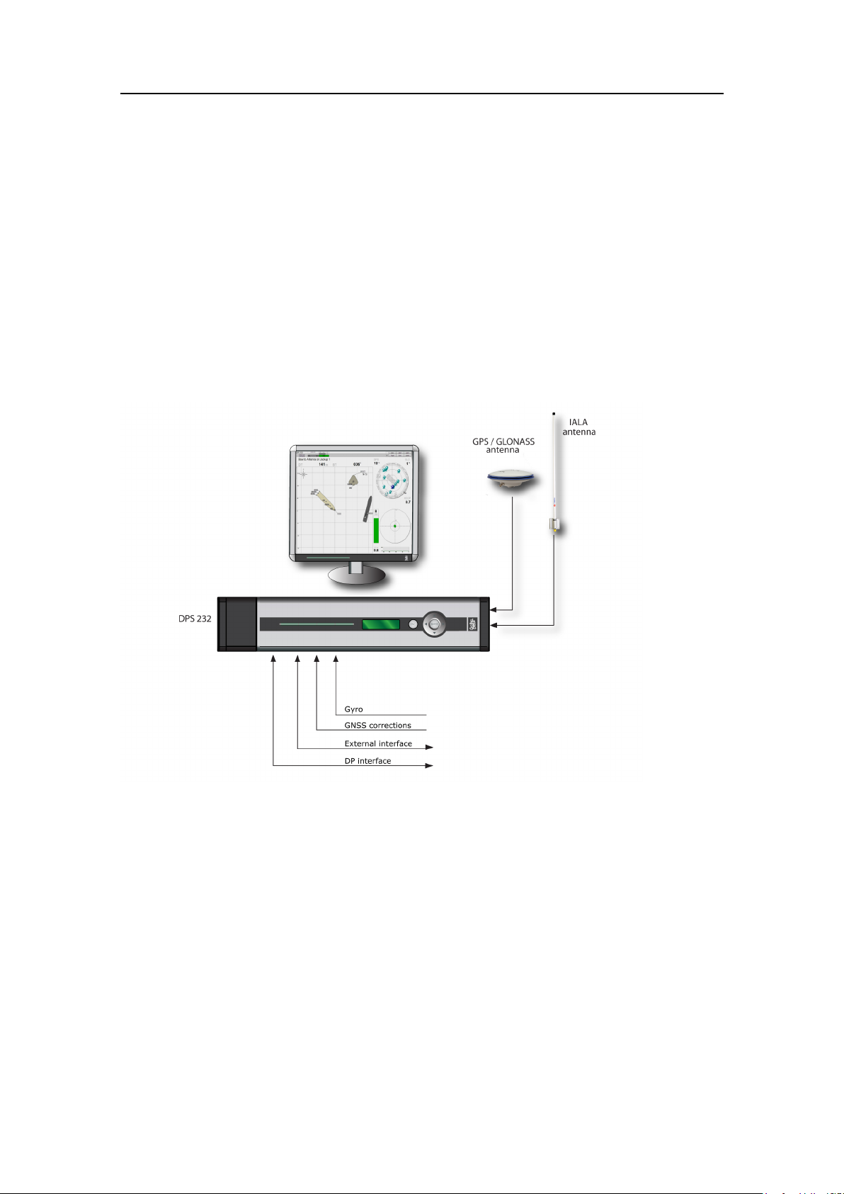
Figure1TypicalDPS232conguration
Inadditiontotheabovedeliveredparts,thefollowingisneeded:
•CoaxcableforGNSSantenna
•CoaxcableforIALAbeaconantenna
•Coaxconnectors
•DGNSScorrectionsononeormoreseriallinesforimprovedpositionaccuracy
(recommended)
•Monitor
•AdditionalcablesforinputofDGNSScorrections
•AdditionalcablesforoutputtoexternalDGNSSequipment
GeneralarrangementdrawingsoftheshipshouldbeacquiredtosimplifyGNSSantenna
mountingandtoestimatesufcientlengthsofcable.
G210-14/3.0
17

KongsbergDPS232
Forexternalinterfaces,electricalcharacteristicsanddataformatsmustbeprovidedas
wellasnecessarycablesandconnectors.
18
G210-14/3.0

3Technicalspecications
3.1Performancedata
3.1.1DPS232system
Technicalspecications
DGPSpositionaccuracywith
SBASservice
DGPS/DGLONASSposition
accuracy
HP/XP/G2positionaccuracy
Velocityaccuracy0.05m/s,95%CEP,0.02m/s,1σ
<1m,95%CEP ,0.6m,1σ
<1m,95%CEP
<0.2m,95%CEP
[2]
,0.4m,1σ
[2]
[1]
[1]
[1]
3.2Physicaldimensions
3.2.1ProcessingUnit
Height88.1mm(2U)
Width485mm(19")
DepthMin357mm(includingconnectorsonrearpanel)and
max412mm(includingcablereliefbracket)
Weight5.4kg
ColourFrontanodizednatural
1.Accuracyspecicationsarebasedonreal-lifetestsconductedusingWAASandanopenviewtothesky
inHouston,Texas.
2.Accuracyspecicationsarebasedonreal-lifetestsconductedunderlowmultipathconditionsandan
openviewtotheskyinTrondheim,Norway.Testsatdifferentlocationsunderdifferentconditionsmay
producedifferentresults.
G210-14/3.0
19

KongsbergDPS232
3.2.2GNSSantenna
Type
Height
Diameter
Weight0.5kg
ColourWhite
Connectortype
TheGNSSantennaisaright-handcircularpolarisedL-bandantennawithanintegral
low-noiseamplier.Theinternalthreadis5/8x11(standardmarinemount).
NovatelGPS-702-GG-N
69.1mm
185mm
N-female
3.2.3IALAbeaconantenna
Type
Height
Weight0.9kg
ColourWhite
TheIALAbeaconantennaisaverticallypolarisedomnidirectionalantenna.Theantenna
canbemountedonverticalorhorizontalmasttubeswith16to54mminouterdiameter.
ComrodAR10A/MF
1100mm
3.2.46Ucabinet
Height
Width
Depth
Depthwithkeyboardext.
Minimumfreespacefrom
wall
3.2.512Ucabinet
Height
Width
Depth
Depthwithkeyboardext.
Minimumfreespacefrom
wall
390mm
553mm
600mm
770mm
20mm
660mm
553mm
600mm
770mm
20mm
20
G210-14/3.0

3.3Power
3.3.1ProcessingUnit
Voltage100to240VAC,50/60Hz
Technicalspecications
Powerconsumption
BatteriesNone,connectiontoUPSrecommended
Max.60W
3.3.2GNSSantenna
Type
Voltage4.5to18VDC(5VDCfromProcessingUnit)
NovatelGPS-702–GG-N
3.3.3IALAbeaconantenna
Type
Voltage9to15VDC(10.2VDCfromProcessingUnit)
ComrodAR10A/MF
3.4Environmentalspecications
3.4.1ProcessingUnit
EnclosurematerialAluminium
Operatingtemperaturerange
Recommendedoperating
temperature
Storagetemperature-20°Cto+70°C
OperatinghumidityMax.95%non-condensing
StoragehumidityLessthan55%
Ingressprotectionfront
Ingressprotectionrear
Electromagneticcompatibility
(immunity/emission)
VibrationIEC60945/EN60945
3.Operatingtemperatureupto+55ºCfor10hours.
-15°Cto+55°C
Roomtemperature(+20°C)
IP42
IP21
IEC60945/EN60945
[3]
G210-14/3.0
21

KongsbergDPS232
3.4.2GNSSantenna
Type
Operatingtemperaturerange
OperatinghumidityHermeticallysealed(100%)
Ingressprotection
NovatelGPS-702–GG-N
-40°Cto+85°C
IP66
3.4.3IALAbeaconantenna
Type
Operatingtemperaturerange
OperatinghumidityHermeticallysealed(100%)
Windrating198km/h
ComrodAR10A/MF
-55°Cto+55°C
3.5Externalinterfaces
3.5.1ProcessingUnit
Serialports6non-dedicatedisolatedports,RS-232orRS-422
IsolatedCom1andCom2,9-pinDSub,RS-232
[4]
BaudrateUpto115200bytes/sec
LAN
USB
4Ethernetports
3ports,1infrontand2inrear
3.6Productsafety
3.6.1ProcessingUnit
Electricalsafety(LVD)IEC60950-1/EN60950-1
4.Numberofserialportsmaybeexpandedbyusingaserialportextender.
22
G210-14/3.0

3.7Radiofrequencies
3.7.1GNSSantenna
Technicalspecications
Type
L11588.5±23.0MHz
L21236.0±18.3MHz
LNAgain(typical)29dB
NovatelGPS-702–GG-N
3.7.2GNSSreceiver
Type
GPSL11575.42MHz
GPSL21227.60MHz
GLONASSL1
GLONASSL2
OEMV2-L1L2–G
1602.0MHzforFk=0wherek=(-7to+13)channel
spacing562.5kHz
1246.0MHzforFk=0wherek=(-7to+13)channel
spacing437.5kHz
3.7.3IALAbeaconreceiver
Type
SBX4
Frequency
280kHzto320kHz
3.8Dataoutputs
3.8.1ProcessingUnit
MessageformatNMEA0183v.3.0,Proprietary
Messagetypes
ABBDP,ARABB,DPGGA,DTM,GBS,GGA,GLL,
GNS,GRS,GSA,GST,GSV,RMC,VBW,VTG,
ZDA
G210-14/3.0
23

KongsbergDPS232
3.9Datainputs
3.9.1ProcessingUnit
DGPS/DGLONASS
corrections
Gyrocompass
3.10Datums
3.10.1ProcessingUnit
Datumtypes
3.11Compasssafedistance
SeaSTARHP,SeaSTARXP,SeaSTARG2,
RTCM-SC104v.2.2and2.3,AISmessagetype17
NMEA0183HDT,HRCandHDM,RobertsonLR22
BCDformat,NMEAPSXN10,NMEAPSXN23,
NMEAPABBS,NMEAPSALS,NMEAPCEGS,
EM3000
NAD27,ED50,WGS84,MINNA,ARA TU-Bahia,
ARATU-Campos,ARATU-ES,ARATU-Santosand
SIRGAS.
3.11.1ProcessingUnit
Standardcompass(mounted
in6Ucabinet)
Othercompass
Note
IftheProcessingUnitisnotmarkedwithacompasssafedistancelabel,theunitshallbe
placedvemetresfromboththesteeringcompassandthestandardcompass.
5.Non-energizedaftermagnetisation(worstcase).
6.Non-energizedaftermagnetisation(worstcase).
2.6m
1.9m
[5]
[6]
24
G210-14/3.0

3.12InterfacesProcessingUnit
3.12.1InterfacesProcessingUnitfront
Thepowerswitch,LAN1andUSB1arelocatedbehindthelid
totheleftonthefrontpanel.Pushlidonleftsidetoopenorip
openusingslitonrightside.
Technicalspecications
3.12.2InterfacesProcessingUnitrear
TherearpaneloftheProcessingUnitcontainscommunicationinterfaceportsfor
interfacingtoexternalequipment.
Figure2RearpanelofProcessingUnitwithconnectorboard
Table1ConnectorsattherearoftheProcessingUnit
Connector
GNSS1
GNSS2
Type
Nconnector50Ohm
female
Nconnector50Ohm
female
Connectedto
GNSSantenna
Notusedinthissystem
IALA
LAN2
USB2USB
USB3USB
G210-14/3.0
Nconnector50Ohm
female
RJ-45–10/100/1000
Mbit/s
IALAbeaconantenna
Usercongurable
Usercongurable
Usercongurable
25

KongsbergDPS232
Table1ConnectorsattherearoftheProcessingUnit(cont'd.)
Connector
LAN3
Type
RJ-45–10/100/1000
Mbit/s
LAN4
RJ-45–10/100/1000
Mbit/s
Mouse
PS/2
KeyboardPS/2Keyboard
COM1
COM2
VGA
COM9
9–pinDSubmale,RS-232Usercongurable
9–pinDSubmale,RS-232Usercongurable
HD15femaleMonitor
5–pinterminal,
RS-232/422
COM10
5–pinterminal,
RS-232/422
COM11
5–pinterminal,
RS-232/422
COM12
5–pinterminal,
RS-232/422
Connectedto
Usercongurable
Usercongurable
Mouse
Usercongurable
Usercongurable
Usercongurable
Usercongurable
COM13
5–pinterminal,
RS-232/422
COM14
5–pinterminal,
RS-232/422
ALARM
MRU
IMU
1PPS
ANALOGOUT
ANALOGIN
100to240VAC
3–pinterminal,relayExternalalarmsystem
10–pinterminal,RS-422Notusedinthissystem
10–pinterminalNotusedinthissystem
6–pinterminalExternalequipment
10–pinterminalUsercongurable
6–pinterminalNotusedinthissystem
Power
Table2ConnectorsatthefrontoftheProcessingUnit
Connector
LAN1
Type
RJ-45–10/100Mbit/sReservedforsupport
USBUSB
Usercongurable
Usercongurable
Inputof100to240VAC
Connectedto
Usercongurable
26
G210-14/3.0
Technicalspecications
Note
Allterminalpinnumberinggoesfromleft(no.1)toright.
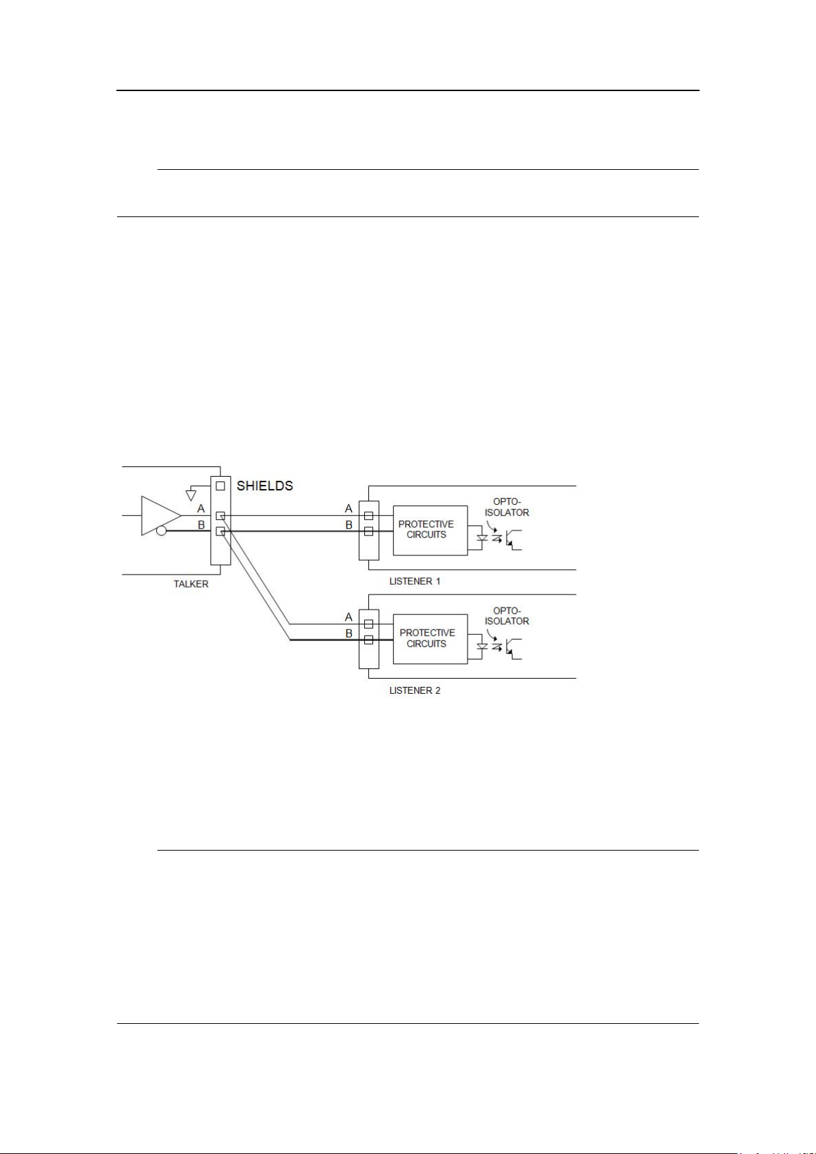
3.12.3RS-422AandBsignaldenition
Accordingtothefollowingstandardthesignalstatedenitionsare:
•IEC61162-1.Theidle,marking,logical1,OFForstopbitstatesaredenedbya
negativevoltageonlineAwithrespecttolineB.Theactive,spacing,logical0,ON
orstartbitstatesaredenedbyapositivevoltageonlineAwithrespecttolineB.
ItshouldbenotedthattheaboveAwithrespecttoBlevelsareinvertedfromthe
voltageinput/outputrequirementsofstandardUARTsandthatmanylinedrivers
andreceiversprovidealogicinversion.
Figure3Principledrawingfortalkerandlistenercircuits
TheRS–422serialportsontheProcessingUnithavegalvanicisolationonbothtalker
(transmit-TX)andlistener(receive-RX).InterfacecircuitsarefedbyaDC/DC
converterwithgalvanicisolation(transformer)andsignalisolationisprovidedby
optocouplerstypeHPCL06.Transmitter/receiverdatacircuitsareoftypeLTC491.The
transmitpartmayfeedupto32listenersiftheminimumDCloadisabove60Ohm.The
receiver-RXterminationintheProcessingUnit(100R)isswitchedonoffbyFW/SW.
Note
Withreferencetothetableshowingthepinlayoutfortheserialportsontherearpanel
screwterminals,notethattheseparate“GND”pinforeachportisisolatedfromthe
chassisandshallactasacommonsignalintendedtobeconnectedbetweenthetalker
(-TX)andthelistenerside(RX)ofotherequipment,forexamplethecorresponding
isolated“GND”pinorcommonpin.Thepurposeofthecommonsignalistoincrease
thereliabilityofthehardwaretransmission.Itmustnotbeconnectedtothechassisor
thecablescreen.Thisappliestobothsidesofaconnection.Thecablescreenshallbe
connectedtotheequipmentchassisononesideonly,preferablytalkerside,-TX.
G210-14/3.0
27
KongsbergDPS232
3.12.4COM1andCOM2
COM1andCOM2attherearoftheProcessingUnitare9-pinDSubmaleandhave
thefollowingpinlayout.
Table3PinlayoutofCOM1andCOM2
Pinno.RS-232Pinno.RS-232
1DCD16DSR1
2RXD1
7
RTS1
3TXD18CTS1
4DTR19RI1
5
Note
GND
COM1and2arenotasaccuratewithregardtotimingasCOM9to14andarenot
recommendedusedfortimingcriticaloutputs.
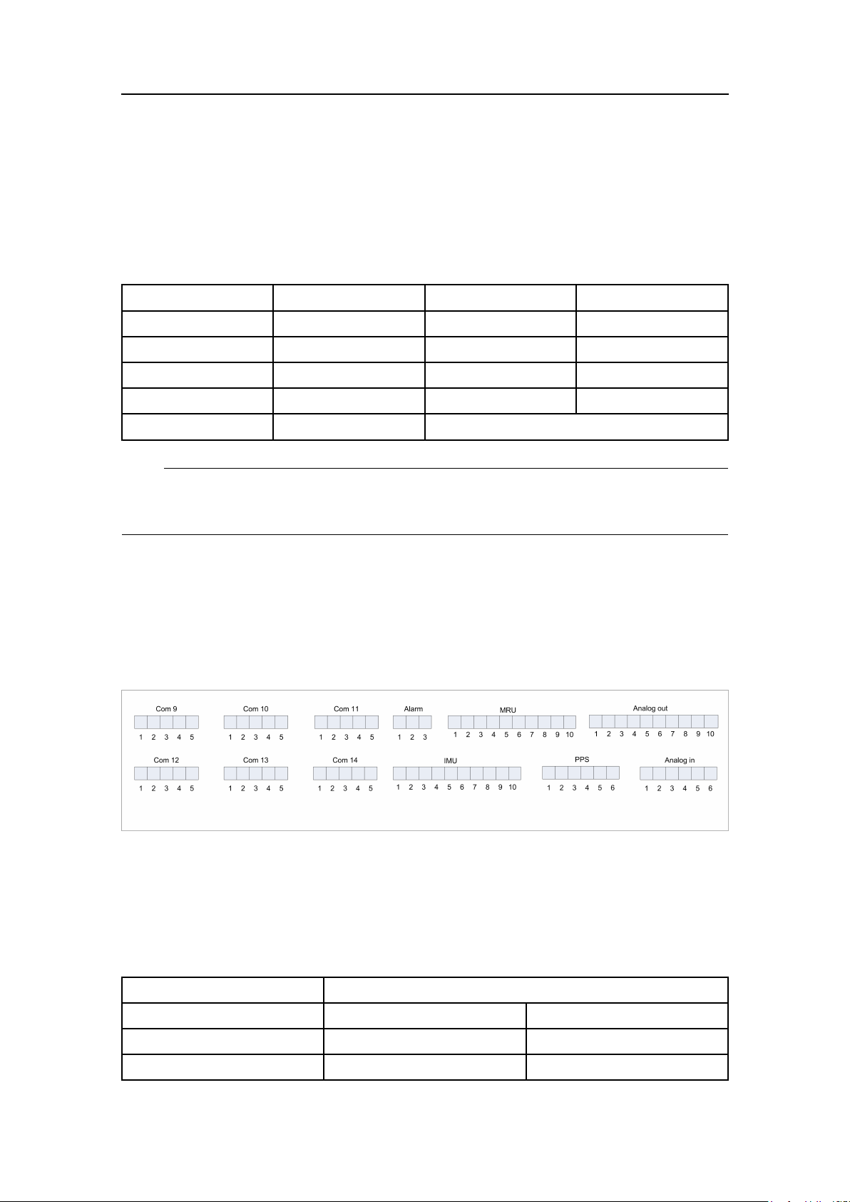
3.12.5Connectorboard
Theillustrationshowsthescrewterminalpinlayoutontheconnectorboardattherear
oftheProcessingUnit.
Figure4Connectorboard
3.12.5.1Seriallines
ThissystemcommunicateswithexternalequipmentthroughtheRS-232orRS-422
congurableserialinputandoutputlines.
Table4Pinlayoutofserialinput/outputlines
Pinno.Signal
RS-422RS-232
1RX_ACTS
2
RX_BRX
28
G210-14/3.0
 Loading...