

Page 1

Instruction Manual
HiPAP®
High Precision Acoustic Positioning
Model 501/451/351/101
Page 2

Page 3

HiPAP®
High Precision Acoustic Positioning
Model 501/451/351/101
Instruction Manual
Page 4

Document history
Rev
Date
Written by
Checked by
Approved by
H
07.03.2013
AJ
AD
JEF
Replaced APC12 with MP8200 8 channel serial line model P/N: 364602.
General updates.
Strandpromenaden 50
P.O.Box 111
N-3191 Horten,
Norway
Kongsberg Maritime AS
Telephone: +47 33 03 41 00
Telefax: +47 33 04 47 53
subsea@kongsberg.com
www.kongsberg.com
Copyright
© 2013 Kongsberg Maritime AS
All rights reserved. The information contained in this document remains the sole
property of Kongsberg Maritime. No part of this document may be copied or
reproduced in any form or by any means, and the information contained within it is not
to be communicated to a third party, without the prior written consent of Kongsberg
Maritime.
Disclaimer
Kongsberg Maritime endeavours to ensure that all information in this document is
correct and fairly stated, but does not accept liability for any errors or omission.
Warning
The equipment to which this manual applies must only be used for the purpose for
which it was designed. Improper use or maintenance may cause damage to the
equipment and/or injury to personnel. The user must be familiar with the contents of
the appropriate manuals before attempting to operate or work on the equipment.
Kongsberg Maritime disclaims any responsibility for damage or injury caused by
improper installation, use or maintenance of the equipment.
Support
All Kongsberg Maritime products:
Phone 24 hour: +47 33 03 24 07
E-mail: km.support@kongsberg.com
Page 5

Instruction Manual
Additional documents
Display manual
Separate manual supplied with the display. Not a Kongsberg Maritime document.
Keyboard manual
Separate manual supplied with the keyboard. Not a Kongsberg Maritime document.
Trackball
Separate document supplied with the trackball. Not a Kongsberg Maritime document.
Air to air heat exchange unit for Transceiver Unit x81
Not a Kongsberg Maritime document.
Air to air heat exchange unit for Transceiver Unit x21
Not a Kongsberg Maritime document.
Remarks
The reader
The installation information in this manual is intended for the design and installation
engineers at the yard performing the installation. The information is supplied as the
basis for the yard’s own installation drawings applicable to the vessel. On completion of
the installation, this section may be used for reference purposes during system
maintenance.
The maintenance information in this manual is intended to be used by a trained
maintenance technician or engineer, with experience of electronic and digital circuitry,
computers and electromechanical design. The level of information is based on
Kongsberg Maritime’s maintenance philosophy: The onboard technical personnel shall,
with the help of the documentation and the system’s built-in test functions, be able to
identify malfunctions, locate the fault, and replace major parts, modules and
components on the “Line Replaceable Unit” (LRU) level. He/she will however not
attempt to repair the LRUs.
303490/H I
Page 6

HiPAP® Model 501/451/351/101
High voltage safety warning
The following safety precautions must be followed at all times
during installation and maintenance work:
Switch off all high-voltage power supplies.
Check the operation of any door interlocks and any other
safety devices.
Completely discharge all high-voltage capacitors.
It should be noted that interlocks and safety devices are
normally located only at regular access points, and high voltages
may be exposed during dismantling.
____________________________________________________________
Caution Never work alone on high-voltage equipment!
Refer to general safety procedures.
____________________________________________________________
II 303490/H
Page 7

Instruction Manual
Table of contents
1 ABOUT THIS MANUAL ........................................................................................ 1
References ......................................................................................................................... 1
Abbreviations .................................................................................................................... 2
Backup ............................................................................................................................... 2
Software upgrade ............................................................................................................... 2
2 SYSTEM DESCRIPTION ....................................................................................... 3
HiPAP® systems - short overview .................................................................................... 4
HiPAP® system configuration .......................................................................................... 4
HiPAP® system with Transceiver unit Model x81 ................................................... 5
HiPAP® system with Transceiver unit Model x21 ................................................... 6
HiPAP® redundant system ....................................................................................... 7
Operator station ......................................................................................................... 8
Transceiver unit (system-specific) ............................................................................ 8
Hull unit (system-specific) ........................................................................................ 9
APOS ................................................................................................................................. 9
Sensors ............................................................................................................................... 9
Conversion kits for upgrading of an “old” HiPAP® system ............................................. 9
System units - short description ...................................................................................... 10
Operator Station ...................................................................................................... 10
Keyboard ................................................................................................................. 11
Trackball.................................................................................................................. 11
Display .................................................................................................................... 11
1PPS converter (option) .......................................................................................... 11
Ethernet switch/Converter ....................................................................................... 11
Fibre Splice Box ...................................................................................................... 12
Transceiver units ..................................................................................................... 12
110 Vac to 230 Vac transformer - option for both transceiver units ....................... 15
3 TECHNICAL SPECIFICATIONS ....................................................................... 16
Operator Station ............................................................................................................... 17
Fibre Splice Box .............................................................................................................. 17
Ethernet switch/Converter ............................................................................................... 18
303490/H III
Page 8

HiPAP® Model 501/451/351/101
Transceiver units.............................................................................................................. 18
Common data .......................................................................................................... 18
Model x81 ............................................................................................................... 19
Model x21 ............................................................................................................... 20
110 Vac to 230 Vac transformer (option) ........................................................................ 20
SSBL accuracy ................................................................................................................ 20
Transducer reference point ...................................................................................... 20
HiPAP® 501 ........................................................................................................... 22
HiPAP® 451 ........................................................................................................... 23
HiPAP® 351 ........................................................................................................... 23
HiPAP® 101 ........................................................................................................... 25
LBL accuracy .................................................................................................................. 25
Range capabilities ............................................................................................................ 27
Fibre-optic cable .............................................................................................................. 28
Patch cables ............................................................................................................. 29
Connector type ST ................................................................................................... 30
4 INSTALLATION ................................................................................................... 31
Supply conditions ............................................................................................................ 33
Equipment responsibility......................................................................................... 33
Installation guidelines ............................................................................................. 33
Assistance from Kongsberg Maritime..................................................................... 33
Before you start ............................................................................................................... 34
Precautions and requirements.................................................................................. 34
Standard tools .................................................................................................................. 34
Special tools ..................................................................................................................... 35
Computer ......................................................................................................................... 35
1PPS converter (option) .................................................................................................. 37
Ethernet switch/Converter ............................................................................................... 37
Fibre Splice Box .............................................................................................................. 37
Transceiver units.............................................................................................................. 38
Basic installation instructions ................................................................................. 38
Vibrations ................................................................................................................ 38
Important information about ventilation and maintenance ..................................... 38
Transceiver unit Model x81 installation.................................................................. 39
IV 303490/H
Page 9

Instruction Manual
Adapter Kit for x81 Transceiver ............................................................................. 41
Transceiver unit Model x21 installation.................................................................. 42
5 CABLES .................................................................................................................. 46
Cable gland assembly procedure ..................................................................................... 47
Securing and terminating the cables........................................................................ 48
Basic cable requirements ................................................................................................. 49
Cable planning ................................................................................................................. 52
Computer ......................................................................................................................... 52
Computer connections ............................................................................................. 52
Computer Dual Net connection ............................................................................... 53
GPS input signals connections ........................................................................................ 54
1PPS converter (option) .................................................................................................. 54
Transceiver unit Model x81 ............................................................................................. 57
Model x81 - transducer cable connection ............................................................... 58
Transducer cable with plug ..................................................................................... 59
Transceiver unit Model x21 ............................................................................................. 61
Model x21 - transducer cable connection ............................................................... 63
Transducer cable with plug ..................................................................................... 63
Transducer to transceiver unit cables installation............................................................ 64
Cable information .................................................................................................... 64
HiPAP® 501/451 .................................................................................................... 65
HiPAP® 351/101 (x81) ........................................................................................... 65
HiPAP® 351/101 (x21) ........................................................................................... 65
Fibre-optic cable installation ........................................................................................... 66
6 OPERATION .......................................................................................................... 69
HiPAP® operation ........................................................................................................... 69
7 MAINTENANCE ................................................................................................... 70
Safety ............................................................................................................................... 71
Before you start ............................................................................................................... 72
Maintenance philosophy .................................................................................................. 72
Verification.............................................................................................................. 73
Maintenance schedule...................................................................................................... 74
Maintenance chart ................................................................................................... 74
Preventive maintenance ................................................................................................... 74
303490/H V
Page 10

HiPAP® Model 501/451/351/101
8 CABLE PLAN AND INTERCONNECTIONS ................................................... 75
9 SYSTEM UNITS - DETAILED DESCRIPTION ............................................... 76
Computer ......................................................................................................................... 76
Computer internal ................................................................................................... 77
How to open the computer ...................................................................................... 78
Keyboard ................................................................................................................. 78
Trackball.................................................................................................................. 78
1PPS converter (option) .................................................................................................. 78
Ethernet switch/Converter ............................................................................................... 78
Replacement ............................................................................................................ 78
Configuration .......................................................................................................... 79
Fibre Splice Box .............................................................................................................. 79
Transceiver unit Model x81 ............................................................................................. 79
Model x81 internal layout ....................................................................................... 80
Model x81 power sockets ........................................................................................ 81
Transceiver unit Model x81, PCB rack ................................................................... 82
Replacement of Model x81 parts ............................................................................ 82
Fuses ........................................................................................................................ 90
Transceiver unit Model x21 ............................................................................................. 91
Model x21 internal layout ....................................................................................... 91
Model x21 power socket ......................................................................................... 93
Replacement of Model x21 parts ............................................................................ 93
Circuit boards and units ................................................................................................... 97
Computer circuit boards and power unit ................................................................. 97
Transceiver units ..................................................................................................... 99
Transmit synchronization with external equipment .............................................. 105
10 SPARE PARTS ................................................................................................. 110
Operator station ............................................................................................................. 110
Transceiver Model x81 .................................................................................................. 111
HiPAP® 501/451/351 system ............................................................................... 111
HiPAP® 101 system ............................................................................................. 112
Transducer cable with plug ................................................................................... 112
Transceiver unit Model x21 ........................................................................................... 113
VI 303490/H
Page 11

Instruction Manual
HiPAP® 351 system ............................................................................................. 113
HiPAP® 101 system ............................................................................................. 113
Transducer cable with plug ................................................................................... 113
11 HIPAP® MODELS AND POSITIONING PRINCIPLES ........................... 114
HiPAP® 501 ......................................................................................................... 115
HiPAP® 451 ......................................................................................................... 115
HiPAP® 351 ......................................................................................................... 116
HiPAP® 101 ......................................................................................................... 116
Positioning principles and processing ........................................................................... 116
SSBL positioning .................................................................................................. 117
LBL positioning .................................................................................................... 118
Combined SSBL and LBL positioning ................................................................. 122
HiPAP® processing .............................................................................................. 123
Cymbal acoustic protocol ...................................................................................... 124
12 RESPONDER OPTION ................................................................................... 126
Basic responder information .......................................................................................... 126
Responder Driver Unit .................................................................................................. 127
Technical specifications ................................................................................................ 128
Responder Driver Unit kit ..................................................................................... 128
Responder Driver Unit .......................................................................................... 128
Fibre to responder drive converter kit ................................................................... 129
Installation ..................................................................................................................... 129
Responder Driver Unit .......................................................................................... 129
Fibre to responder drive converter ........................................................................ 130
Cable layout and interconnections ................................................................................. 130
Maintenance................................................................................................................... 130
Responder Driver Unit .......................................................................................... 130
Fibre to responder drive converter ........................................................................ 132
Spare parts ..................................................................................................................... 133
Drawings ........................................................................................................................ 133
Responder Driver Unit - outline dimension .......................................................... 134
Responder Driver Unit .......................................................................................... 135
Responder sync cable, Transceiver unit Model x21 ............................................ 136
303490/H VII
Page 12

HiPAP® Model 501/451/351/101
Responder sync cable, Transceiver unit Model x81 ............................................ 136
Responder Driver Unit - wiring diagram .............................................................. 137
Fibre to responder drive converter - wiring diagram ........................................... 138
13 LASER OPTION .............................................................................................. 139
Basic laser information.......................................................................................... 139
Installation ............................................................................................................. 141
Cable layout and interconnections ........................................................................ 141
Maintenance .......................................................................................................... 142
Spare parts ............................................................................................................. 143
Laser kit for TU Model x81 .................................................................................. 143
Drawings ............................................................................................................... 143
TU Model x81 – wiring diagram w/laser .............................................................. 144
Hoist indicator ADAM 617 – wiring diagram ...................................................... 145
14 EQUIPMENT HANDLING ............................................................................ 146
Transportation ................................................................................................................ 146
Storage prior to installation or use ........................................................................ 147
Inspection .............................................................................................................. 149
Storage after unpacking ................................................................................................. 152
After use storage.................................................................................................... 153
Re-packing ..................................................................................................................... 154
ESD precautions ............................................................................................................ 154
Temperature protection.................................................................................................. 155
15 HIPAP® COMMISSIONING CHECK AND VERIFICATION ................. 156
16 DRAWING FILE .............................................................................................. 157
Drawings ........................................................................................................................ 158
Keyboard - outline dimensions ............................................................................. 159
19“ display - outline dimensions ........................................................................... 160
Computer - desktop mounting and outline dimensions ......................................... 161
Computer - rack mounting and outline dimensions .............................................. 162
Transceiver unit Model x81, with cooling unit mounted on the right side - outline
dimensions/mounting, page 1 ................................................................................ 163
VIII 303490/H
Page 13

Instruction Manual
Transceiver unit Model x81, with cooling unit mounted on the right side - outline
dimensions/mounting, page 2 ................................................................................ 164
Transceiver unit Model x81, with cooling unit mounted on the front door (option) -
outline dimensions/mounting, page 1.................................................................... 165
Transceiver unit Model x81, with cooling unit mounted on the front door (option) -
outline dimensions/mounting, page2..................................................................... 166
Transceiver unit Model x21 - outline dimensions/mounting, page 1 ................... 167
Transceiver unit Model x21 - outline dimensions/mounting, page 2 ................... 168
Standard AC power cable ...................................................................................... 169
EMC ground cable ................................................................................................ 170
External trigger cable ............................................................................................ 170
Computer RS-232 / RS-422 serial line cable ........................................................ 171
Transducer cable for HiPAP® 501/451 system, page 1 ........................................ 173
Transducer cable for HiPAP® 501/451 system , page 2 ....................................... 174
Transducer cable for HiPAP® 351/101 system, w/Transceiver unit Model x81,
page 1 .................................................................................................................... 175
Transducer cable for HiPAP® 351/101 system, w/Transceiver unit Model x81,
page 2 .................................................................................................................... 176
Transducer cable for Transceiver unit Model x21, page 1 .................................... 177
Transducer cable for Transceiver unit Model x21, page 2 ................................... 178
Transducer hull unit cable, for all HiPAP® systems, page 1 ................................ 179
Transducer hull unit cable, for all HiPAP® systems, page 2 ................................ 180
Transceiver unit Model x81 - wiring diagram ..................................................... 181
Transceiver unit Model x21 - wiring diagram, page 1 ......................................... 182
Transceiver unit Model x21 - wiring diagram, page 2 ......................................... 183
Cable conversion kit for Transceiver unit Model x81 - drawing .......................... 184
Adapter Kit for Transceiver x81 Unit ................................................................... 185
Junction box conversion kit for Transceiver unit Model x21 – drawing, page 1 .. 186
Junction box conversion kit for Transceiver unit Model x21 – drawing, page 2 .. 187
1PPS converter – component layout drawing ....................................................... 188
17 CABLE PLAN AND INTERCONNECTIONS ............................................. 189
18 INDEX ............................................................................................................... 190
303490/H IX
Page 14

Page 15

1 ABOUT THIS MANUAL
This document is the Instruction manual for the (High Precision
Acoustic Positioning) HiPAP® Model 501/451/351/101 systems
(named HiPAP® systems in rest of the manual).
The manual contains descriptions, specifications, procedures
and illustrations required to install and maintain the HiPAP®
system units.
The manual also defines the equipment responsibility, and
provides general information about preservation, packing and
storage of the units, and provides the Factory Acceptance Tests
and the HiPAP® test and alignment procedures.
The system is described down to circuit board level, named as
the Line Replaceable Units (LRUs). Block diagrams and
drawings are used to simplify the descriptions.
About this manual
References
Conversion kits for upgrading of old HiPAP® systems are also
included.
319957 - APOS for HiPAP® 501/451/351/101 Instruction Manual
311046 - HiPAP® hull units Model 501/451/351/101 Instruction
Manual
331070 - HiPAP® Commissioning check and verification
859-216300 - Backup files document
303490/H 1
Page 16

HiPAP® Model 501/451/351/101
APOS
Acoustic Positioning Operator Station
BOP
Blow Out Preventer
CG
Centre of Gravity
DP
Dynamic Positioning
DVI
Digital Visual Interface
GNSS
Global Navigation Satellite System
GPS
Global Positioning System
HiPAP®
High Precision Acoustic Positioning
HPR
Hydroacoustic Position Reference
LBL
Long Base Line
LRU
Line Replaceable Unit
MULBL
Multi-User Long Base Line
PCB
Printed Circuit Board
ROV
Remotely Operated Vehicle
RTB
Responder Terminal Block
SSBL
Super Short Base Line
SSLBL
Super Short and Long Base Line
Abbreviations
Abbreviations used in this manual:
Backup
You are advised to take a backup of all operator stations at
regular intervals (1-3 months), and every time major changes
have been performed in configuration and /or user settings.
Software upgrade
____________________________________________________________
Caution A system backup must be performed when the
software has been upgraded.
____________________________________________________________
The backup procedures are included in a separate document, the
Backup files document, doc no 859-216300.
This document is supplied with every system delivered.
2 303490/H
Page 17

2 SYSTEM DESCRIPTION
This chapter provides a brief description of the HiPAP®
systems and configurations. It also gives a short description of
each unit.
Topics
HiPAP® systems - short overview on page 4
HiPAP® system configuration on page 4
Operator station on page 8
Transceiver units on page 8
Hull units on page 9
APOS on page 9
System description
Sensors on page 9
Conversion kits for upgrading of old HiPAP® systems on page 9
System units - short description on page 10
Related topics
HiPAP® models information on page 114
Responder option on page 126
Laser option on page 139
303490/H 3
Page 18

HiPAP® Model 501/451/351/101
HiPAP® systems - short overview
The HiPAP® systems are designed for optimal positioning of
subsea objects in both shallow and deep water.
All HiPAP® systems; HiPAP® 501, HiPAP® 451, HiPAP®
351 and HiPAP® 101 have common software and hardware
platforms, and thereby offer the same kind of additional
functionality and options.
The HiPAP® 501, HiPAP® 451, HiPAP® 351 systems are
medium frequency systems operating from 21 kHz to 31 kHz.
The HiPAP® 101 system is a low frequency systems
operating from 10 kHz to 15.5 kHz.
HiPAP® system configuration
A HiPAP® system may be configured as:
Standard HiPAP® systems:
HiPAP® systems used with Transceiver unit Model x81,
see figures on page 5
HiPAP® systems used with Transceiver unit Model x21,
see figure on pages 6
HiPAP® Dual Net system:
HiPAP® systems used with Transceiver unit Model x81,
see figure on page 7
4 303490/H
Page 19
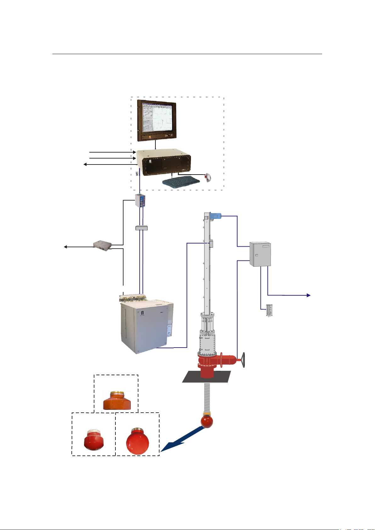
(Cd31053a)
Operator
Station
Heading sensor
Motion sensor
Data output
Fibre B (optional)
Ethernet
Ethernet
Ethernet interfaced
with APOS/APC
Fibre A
Responder sync.
Fibre A
Fibre B
Hull
Unit
Ethernet
switch/
Converter
Fibre Splice
Box
Junction
Box
Responder
Driver Unit (option)
Responder
Transceiver unit
Model x81
Hoist
Control Unit
Remote
Control
Unit
HiPAP 100
transducer
HiPAP 350
transducer
HiPAP 500
transducer
Option 1
Option 2
System description
HiPAP® system with Transceiver unit Model x81
303490/H 5
Page 20
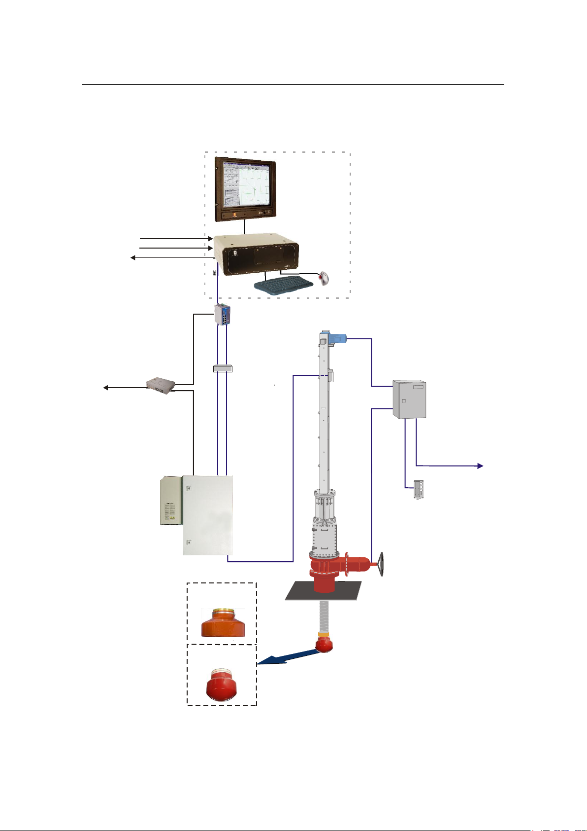
Ethernet
Responder sync.
Responder
Driver Unit (option)
Responder
(Cd31053)
Transceiver unit
Model x21
Hoist
Control Unit
Operator
Station
Heading sensor
Motion sensor
Data output
Ethernet
Fibre A
Fibre B (optional)
Fibre A
Fibre B
Hull
Unit
Ethernet
switch/
Converter
Fibre Splice
Box
HiPAP 100
transducer
HiPAP 350
transducer
Junction
Box
Ethernet interfaced
with APOS/APC
Remote
Control
Unit
Option 1
Option 2
HiPAP® Model 501/451/351/101
HiPAP® system with Transceiver unit Model x21
6 303490/H
Page 21
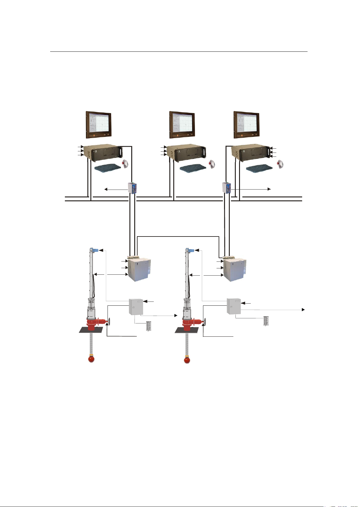
HiPAP® redundant system
Operator Station Operator Station
Operator Station
Dual Ethernet
Ethernet
Ethernet
Fibre A
Fibre A
Fibre B (optional)
Fibre B (optional)
Hoist
Control Unit
Hull Unit
Hull Unit
Power
Power
Hoist
Control Unit
Power A
Power A
Power B
(option)
Power B
(option)
Power
(Cd31085)
Gate valve
Gate valve
position indicator
Gate valve
position indicator
HiPAP 500/350
transducer
Power
Gate valve
HiPAP 500/350
Remote
Control
Unit
Remote
Control
Unit
GPS
GPS
GPS
Heading sensor
Heading sensor
Heading sensor
Motion sensor
Motion sensor
Motion sensor
Responder
Responder
Ethernet
switch/
Converter
Ethernet
switch/
Converter
HiPAP
Transceiver Unit
Model x81
500
HiPAP
Transceiver Unit
Model x81
500
(Sync for Dual HiPAP only)
Ethernet interfaced
with APOS/APC
Ethernet interfaced
with APOS/APC
Option 1
Option 1
Option 2
Option 2
Example of a HiPAP® redundant system:
System description
303490/H 7
Page 22

HiPAP® Model 501/451/351/101
Operator station
The operator station may be configured in two ways:
1. Stand alone
Computer
Display
Keyboard
Trackball
The stand alone configuration can be fitted as:
Contained in a standard 19” rack
The display and the computer are fitted into a standard
19” rack unit. The keyboard and the trackball may be
placed on a desk, or on a suitable shelf. The transceiver
unit is installed close to the hull unit.
The display, the computer and the keyboard are fitted
into drawers in a standard 19” rack unit.
Desktop system
The display, the computer, the keyboard and the
trackball sit on a desk top or a purpose-built shelf.
2. Operator console
If the HiPAP® system is delivered together with a Kongsberg
DP system the operator station may be installed in a standard
Kongsberg DP console.
Transceiver unit (system-specific)
Two types of transceiver units are available:
HiPAP® Transceiver unit Model x81are used for the
systems 501, 451 and 351.
HiPAP® systems used with Transceiver unit Model x81,
see figures on pages 5 and 7.
HiPAP® Transceiver unit Model x21 are used for the
systems 351 and 101.
8 303490/H
Page 23

APOS
Sensors
System description
HiPAP® systems used with Transceiver unit Model x21,
see figure on page 6.
Hull unit (system-specific)
Hull units w/transducer, gate valves, Hoist Control Unit with
Ethernet interface are described in the HiPAP® hull units Model
501/451/351/101 Instruction Manual.
The HiPAP® system is operated from APOS, a Windows based
software system. The system can be operated from one single
APOS station or from a wide number of APOS operator stations
connected on a network.
The HiPAP® system has a wide range of interfaces to sensors
from different manufacturers.
The HiPAP® system needs high accuracy heading, roll and
pitch sensors to be interfaced.
The accuracy of the sensors has direct impact on the position.
Conversion kits for upgrading of an “old” HiPAP® system
Transceiver unit Model x81 to be used with a transducer cable
with plug.
See information on page 59
Transceiver unit Model x21 to be used with a transducer cable
with plug.
See information on page 63
For more information, contact Kongsberg Maritime.
303490/H 9
Page 24

HiPAP® Model 501/451/351/101
System units - short description
Topics
Operator Station on page 10
Keyboard on page 11
Trackball on page 11
Display on page 11
1PPS converter on page 11
Ethernet switch/ Converter on page 11
Fibre Splice Box on page 12
Transceiver units on page 12
Operator Station
The HiPAP® System is operated through either one or several
Operator Stations.
The Operator Station consists of the following main units:
A Windows™ based personal computer
A display for presentation of information
Keyboard and mouse
The same computer is used for all types of installation, desktop
or rack with additional mounting brackets or rails as required.
Power
The computer can be powered from either a 115 VAC or 230
VAC supply.
USB disk
An USB disk containing programs for backup and restore is
delivered at the system setup. These programs can only be used
when the system boots from the USB disk.
10 303490/H
Page 25
System description
(Cd31162)
Keyboard
The keyboard is a PS/2 keyboard. It is a QWERTY keyboard
with US layout and includes back-lighting.
Trackball
The trackball is a standard trackball with a scroll wheel and
three buttons.
Display
Refer to the separate manual supplied with the display.
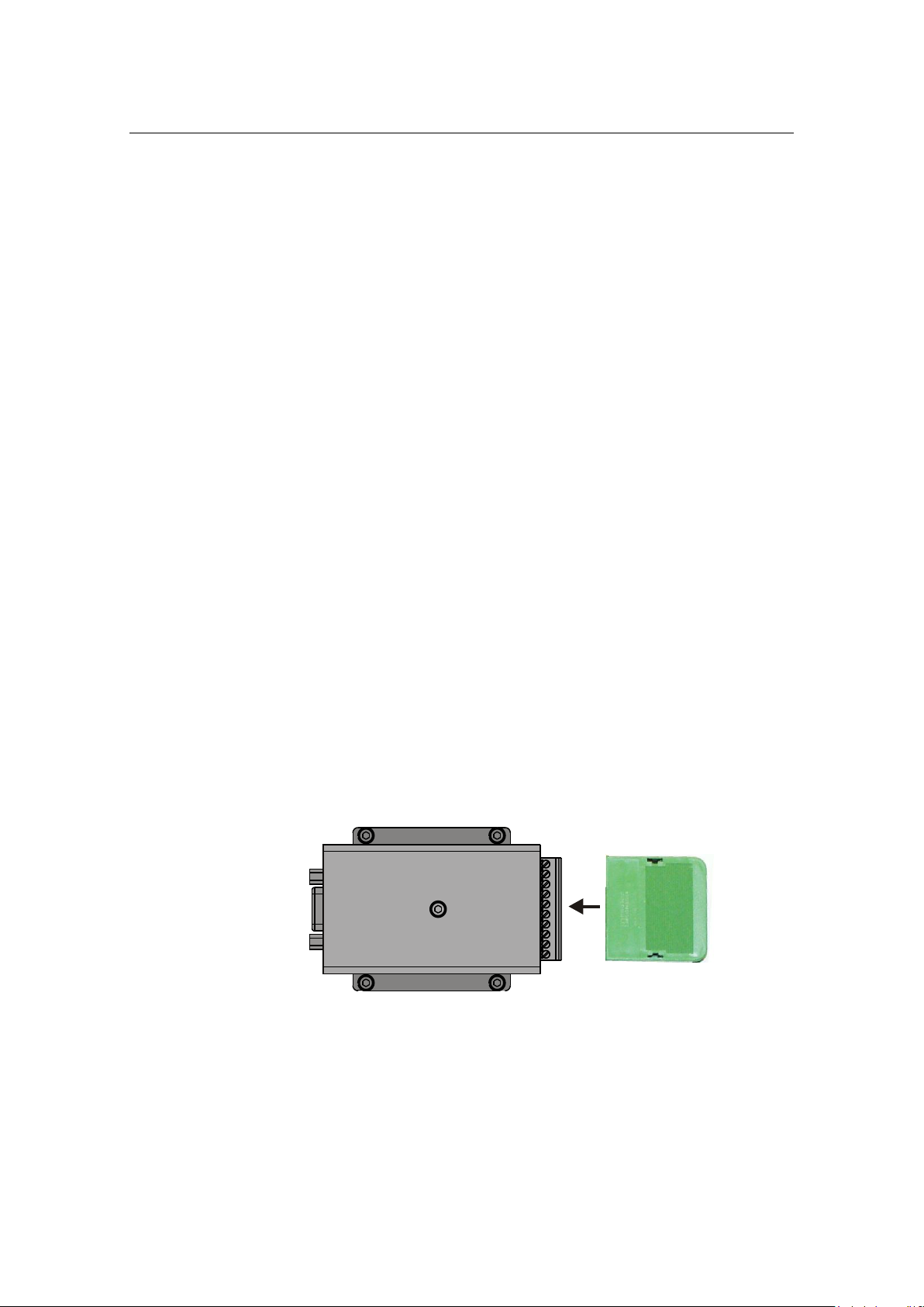
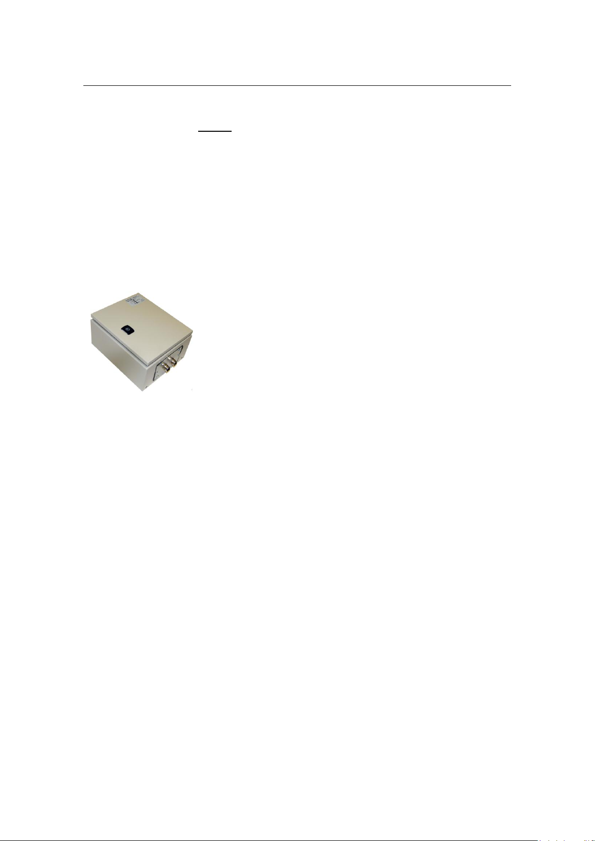
1PPS converter (option)
The 1PPS converter is an option to a standard HiPAP® system.
1PPS; One Pulse per Second.
The signal is normally taken from a GPS receiver or a time
synchronize unit.
This pulse is used to synchronize the clock on the APOS/HiPAP
system with a reference clock.
In addition to the pulse, a message with correct time must be
transmitted on the same serial line as used for the 1PPS input.
A 1PPS converter passes the RS-232 GPS Position Data through
but shapes the 1PPS pulse to a fixed pulse length and converts it
from TTL level to RS-232 level.
Figure 1 1PPS converter
Ethernet switch/Converter
The Ethernet switch/Converter is used for:
Interface Optical fibre cable to transceiver
303490/H 11
Page 26

HiPAP® Model 501/451/351/101
Responder Driver Unit
Hoist Control Unit with Ethernet
Gate Valve Main Control Unit with Ethernet
Fibre Splice Box
The Fibre Splice Box has eight (8) ports. This box is used to
splice the system fibre-optic cables.
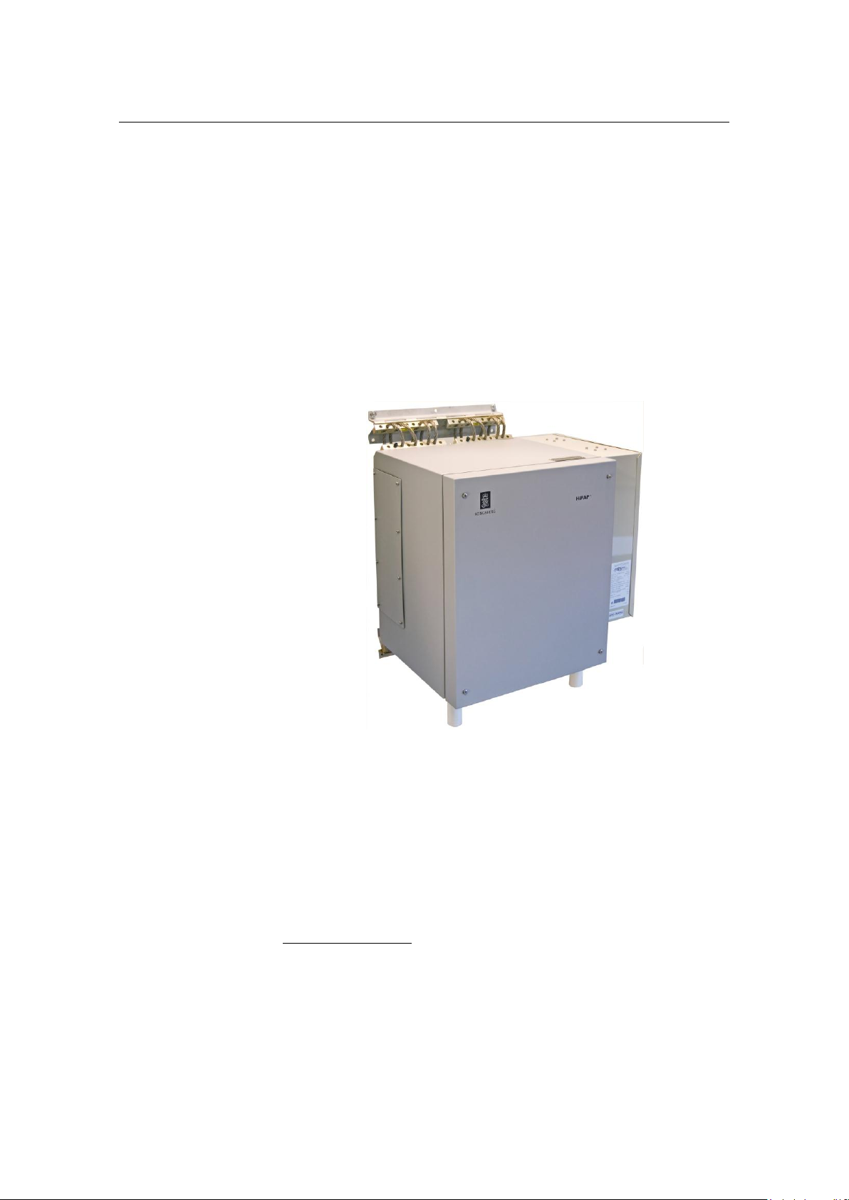
Transceiver units
The HiPAP® transceiver units are steel cabinets, containing a
rack holding the system electronics modules. The units are fitted
with an air to air heat exchange unit.
The transceiver units are designed to be mounted on a suitable
bulkhead and are fitted with vibration/shock absorbers to reduce
the effects of transceiver unit vibrations.
Topics
Transceiver unit Model x81 on page 13
Transceiver unit Model x21 on page 14
12 303490/H
Page 27
System description
Transceiver unit Model x81
Transceiver unit x81 may be delivered with:
With the air to air heat exchange unit mounted on the right
side as standard.
or
With the air to air heat exchange unit mounted on the unit
door (optional).
An access door for plugging connectors and service is located
on the left side of the unit.
Figure 2 Standard Transceiver unit Model x81 w/air to air heat exchange unit mounted
on the right side
Used for the HiPAP® 501 with eight (8) TRX32 boards
Used for the HiPAP® 451 with two (2) TRX32 boards
Used for the HiPAP® 351 with two (2) TRX32 boards
Used for the HiPAP® 101 with one (1) TRX32 board
System upgrade
The HiPAP® 451 can be upgraded to full HiPAP® 501
performance. This is done by:
Installation of 6 additional transmitter/receiver boards
(TRX32) in the transceiver unit.
APOS software upgrade.
303490/H 13
Page 28
HiPAP® Model 501/451/351/101
(Cd31072)
Connections
All cables to and from the transceiver unit enter the unit through
the base of the unit.
Power
The transceiver unit is powered from a 230 Vac supply. The
power switch (Main switch) is located inside the transceiver
unit.
Refer to figure on page 80
If you only have 110 Vac power available, you must use a 110
Vac to 230 Vac transformer - see page 15.
Transceiver unit Model x21
Transceiver unit x21 are delivered with the air to air heat
exchange unit mounted on the left side.
Figure 3 Transceiver unit Model x21
Used for the HiPAP® 351 with two (2) TRX32 boards
Used for the HiPAP® 101 with one (1) TRX32 board
Connections
All cables to and from the transceiver unit enter the unit through
the base of the unit.
14 303490/H
Page 29
System description
If your only have 110 Vac power available, an external
transformer from 110 Vac to 220 Vac must be installed on the
main power line to both the Transceiver unit Model x81 and
the Transceiver unit Model x21
Order no see page 20
Power
The transceiver unit is powered from a 230 Vac supply. The
power switch (Main switch) is located inside the transceiver
unit.
Refer to figure on page 91
If you only have 110 Vac power available, you must use a 110
Vac to 230 Vac transformer - see page 15.
110 Vac to 230 Vac transformer - option for both transceiver units
303490/H 15
Page 30

HiPAP® Model 501/451/351/101
3 TECHNICAL SPECIFICATIONS
This chapter gives the technical specifications of the HiPAP®
system units.
Topics
Operator station on page 17
Fibre Splice Box on page 17
Ethernet switch/Converter on page 18
Transceiver unit Model x81 on page 18
Transceiver unit Model x21 on page 20
110 Vac to 230 vac transformer - option on page 20
SSBL accuracy on page 20
LBL accuracy on page 25
Range capabilities on page 27
Fibre-optic cable on page 28
Related topics
Transmit on external trigger on page 105
16 303490/H
Page 31

Operator Station
Weight:
7.6 kg
Dimensions (WxDxH):
338 x 379 x 100 mm
Voltage:
110/220 VAC
50/60 Hz autosensing
240 W 85+ autosensing power
Parallel port:
1 x HP Parallel Port Adapter
Serial port:
COM1
8 port Bluestorm card
USB:
8 x USB 2.0
VGA:
1 x VGA – implemented on
motherboard
Display port:
1 x Display port – implemented on
motherboard
Display port adapter (HP Display
port to DVI-D Adapter)
Audio:
1 x Audio in
1 x Audio out
Integrated High Definition audio
with AD1884 codec
Others:
2 x PS2
1 x Headphone/line-out
1 x Microphone in
Outline dimensions - see drawing in the Drawing file chapter
from page 157
Power specifications
Connections
Technical specifications
Fibre Splice Box
303490/H 17
Eight (8) ports MX-WFR-00024-02.
Page 32

HiPAP® Model 501/451/351/101
Degree of protection:
IP 44
Voltage:
230 Vac
The power supply to a HiPAP® transceiver unit must be
kept within +10% of the unit’s nominal voltage.
The maximum transient voltage variations on the main
switch- board’s bus-bars which could occur (except under
fault conditions), are not to exceed -15% to +20% of the
nominal voltage.
Using 110 Vac to 230 Vac transformer (option) - see page
20
Inrush max:
35 A Ac
Maximum current drawn:
2.5 A
Nominal:
1.6 A Ac
Frequency:
50 - 60 Hz
Nominal power consumption:
370 W
Operating temperature:
0° C to +55° C
Storage temperature:
-20 to +65° C
Humidity:
15% - 95% (non condensing)
Range:
5-100 Hz
For more information, refer to the supplier
Ethernet switch/Converter
The converter requires a power supply. The DR-4524 DIN-rail
24 Vdc Power Supply is used.
Transceiver units
Common data
This data is the same for x81 and x21 transceiver units.
Power
Environment
Vibration
18 303490/H
Page 33

Technical specifications
Excitation level:
5-13.2 Hz ±1.5 mm, 13.2-100 Hz 1 g
Weight:
approximately 80 kg
(depending on number of PCBs fitted)
Input:
230 Vac
The HiPAP transceiver accepts the following input formats:
Gyro:
NMEA $**HDT
NMEA $**VHW
Yokogawa $**HRC
SKR
STL
VRU / Attitude:
EM 3000
$SPSXN,10
$SPSXN,23
IxSea Octans TAH ($PHOCT) R-P-H (UTC)
IxSea Octans $PHTRO (roll and pitch)
Ixsea Octans $PHLIN (Heave only)
Data input can be either serial line RS-232 / RS-422 or Ethernet
UDP.
Serial line speeds can be from 1200 baud up to 115200 baud, 1
or 2 stop bits, 7/8 bit data and parity none, even or odd.
Note For attitude data, the data rate should be at least 25 Hz, 100 Hz
is recommended.
Model x81
303490/H 19
Outline dimensions - see drawing in the Drawing file chapter
from page 157
Main power supply
Page 34

HiPAP® Model 501/451/351/101
Output:
24 Vdc, 12 Vdc, 6 Vdc, 5 Vdc,
3.2 Vdc
Input:
230 Vac
Output:
48 Vdc
Weight:
approximately 35 kg
(depending on number of PCBs fitted)
Input:
230 Vac
Output:
48 Vdc, 24 Vdc12 Vdc, 5.4 Vdc
Order no.:
319618
Weight:
7. 8 kg
Outline dimensions:
( 300 x 250 x 155) mm
Model x21
Outline dimensions - see drawing in the Drawing file chapter
from page 157
Main power supply
110 Vac to 230 Vac transformer (option)
For installations where only 110 Vac power is available, an
external transformer from 110 Vac to 220 Vac must be installed
on the main power line to the transceiver units.
SSBL accuracy
The angular figures are errors in both axis, elevation and
orthogonal.
The specification is based on:
Free line of sight from transducer to transponder.
No influence from ray-bending.
Signal to Noise ratio in water in the 250 Hz receiver band.
20 303490/H
No error from heading and roll / pitch sensors.
Transducer reference point
Page 35

Technical specifications
HiPAP® 500 transducer
HiPAP® 350 transducer
(Cd31154)
0 elevation
O
Orthogonal
90 elevation
O
= reference point
A= radius = 196 mm
B= radius = 196 mm
Center of
transducer
(Cd31154a)
0 elevation
O
Orthogonal
90 elevation
O
= reference point
A= radius = 160 mm
B=196 mm
Center of
transducer
HiPAP® 100 transducer
(Cd31154b)
0 elevation
O
Orthogonal
90 elevation
O
= reference point
A= radius = 225 mm
B= radius = 225 mm
Center of
transducer
The reference points shown below are the origin for the position
measurements.
The elevation and orthogonal angles are used in the accuracy
curves.
303490/H 21
Page 36

HiPAP® Model 501/451/351/101
HiPAP® 501 Single
system
HiPAP® 501 Dual system
S/N [dB rel. 1Pa]
S/N [dB rel. 1Pa]
20
10 0 20
10
0
Angular Accuracy []
(At 0 elevation)
0.12
0.18
0.3
0.085
0.13
0.21
Range Accuracy [m]
0.1
0.1
0.15
0.1
0.15
0.15
Cymbal Range Accuracy [m]
0.02
0.02
0.02
0.02
0.02
0.02
Receiver beam []
10
10
Coverage []
±100
±100
HiPAP 501
(Cd31183)
HiPAP® 501
Accuracy curves – HiPAP® 501
The figure above shows the accuracy as a function of elevation
angle. The signal to noise ratio of 10 dB is in the bandwidth.
22 303490/H
Page 37

Technical specifications
HiPAP 501 Performance
(Cd31184)
HiPAP® 351/451
Single system
S/N [dB rel. 1Pa]
20
10
0
Angular Accuracy, 1 []
(At 0 elevation)
0.18
0.23
0.4
Range Accuracy, 1 [m]
0.1
0.15
0.2
Cymbal Range Accuracy, 1 [m]
0.02
0.02
0.02
Receiver beam []
15
Coverage []
+/-80
The figure above shows the accuracy as a function of signal to
noise ratio. The elevation and the orthogonal angles are 0 (at
vertical).
HiPAP® 451
The HiPAP® 500 transducer is used. HiPAP® 451 has the same
technical performance as HiPAP® 351.
HiPAP® 351
The elevation and orthogonal angles are used in the accuracy
curves.
303490/H 23
Page 38

HiPAP® Model 501/451/351/101
HiPAP 351 Performance
(Cd31185)
(Cd31186)
HiPAP 351 Performance
Accuracy curves – HiPAP® 351
The figure above shows the accuracy as a function of elevation
angle. The signal to noise ratio 10 dB is in the bandwidth.
The figure above shows the accuracy as a function of signal to
noise ratio. The elevation and the orthogonal angles are 0 (at
vertical).
24 303490/H
Page 39

HiPAP® 101 system
S/N [dB rel. 1Pa]
20
Angular Accuracy, 1 []
(At 0 elevation)
0.14
Range Accuracy, 1 [m]
0.2
Cymbal, Range Accuracy,
1 [m]
0.02
Receiver beam []
15
Coverage []
+/-60
LBL accuracy
Source of random error
1-sigma FSK
1-sigma Cymbal
Range reception with 20 dB S/N
0.15 m
0.02 m
Range reception in the transponder
0.15 m
0.02 m
Range error due to transponder
movements
0.01 m
Range error due to rig movements
0.05 m
HiPAP® Angle accuracy
0.15°
Technical specifications
HiPAP® 101
The position accuracy for LBL operation depends on the
transponder array geometry, sound velocity errors and signal to
noise ratio. Range accuracy’s down to a few centimetres can be
obtained, while ROV and vessel positions can be calculated to
within a few decimetres.
Table 1 and Figure 4 show acoustic parameters and position
accuracies that are achieved in deep waters when using an array
with four transponders at water depth 3000m.
Table 1 Sources of random errors on the acoustic measurements
303490/H 25
Page 40

HiPAP® Model 501/451/351/101
-400 -200 0 200 400
0
0.2
0.4
0.6
0.8
1
1.2
1.4
1.6
1.8
2
CW
Cymbal
Sound velocity
HiPAP LBL horizontal accuracy. Waterdepth 3000m.
East co-ordinate relative to centre of LBL array
Horizontal position error
Figure 4 LBL position error in the horizontal plane as a function of the East co-
ordinate. The North co-ordinate is zero. The blue lines show random error due to
acoustics. Black line is systematic error due to 1 m/s wrong sound velocity settings.
The blue lines in Figure 4 show the random error in the
horizontal position when the rig moves within a transponder
array with 4 transponders placed on a circle with 500 m radius at
water depth 3000 m. The lower line shows the expected error
when the Cymbal acoustics is used and the upper line when the
old CW acoustics is used.
The black line shows the systematic error when the sound
velocity is set 1 m/s incorrectly in APOS. This error is zero in
the centre of the array due to the symmetry. The LBL run time
calibration should be done when the rig is in the centre of the
array. Then the effect of a wrong sound velocity setting in
APOS is strongly reduced, as shown with the dotted black line.
26 303490/H
Page 41

Range capabilities
Transponder
Transponder source level
(dB rel.1Pa ref. 1 m)
Max Range
(Typical, m)
cNODE®, 180º
transducer
190
2000
cNODE®, 40º transducer
203
3000
cNODE®, 30º transducer
206
4000
Standard MPT/SPT 319
188
1500
High power SPT 324
195
2000
High power SPT 331
206
3000
The range capabilities of an acoustic system are dependent of
the vessels noise level and attenuation of the transponder signal
level due to ray bending. The transponder source level and the
signal to noise ratio are crucial factors for calculating maximum
range capability. The below figures are recommended guideline
for maximum operating range.
Please also be aware of:
The figures are valid for HiPAP® 501/351/451
Figures for cNODE® are when used in Cymbal mode
(Wideband)
The HiPAP® system will in many cases have longer range
capabilities that specified below due to its narrow receiving
beam.
Technical specifications
The figures are approximate values for guidance.
Ray bending can limit the maximum range
Ray bending normally not a problem for vertical positioning
operation
The specification is based on:
Free line of sight from transducer to transponder
303490/H 27
No influence from ray bending
Signal to Noise ratio 12 dB. rel. 1Pa
Page 42

HiPAP® Model 501/451/351/101
Supplier part no.
KM
part no.
Cable type
Configuration
507-UB04-080UALT/900
324994
Multimode OM 3
Fibre 50/125 μm
4 fibres, free length without
connectors, flame retardant,
halogen free
Cable diameter:
8.0 mm
Total cable weight:
65 kg/km
Operating temperature:
-40 C to +85 C
Installation temperature:
-10 C to +60 C
Storage temperature:
-55 C to +85 C
Minimum bend radius:
180 mm
Maximum tensile load:
2000 N
Fibre-optic cable
The following table shows recommended cable for use in
Kongsberg Maritime networks.
28 303490/H
Figure 5 Fibre-optic cable details
Cable data
Installation
Page 43

Operating
Minimum bend radius:
180 mm
Maximum tensile load:
800 N
Cord diameter:
2.5 mm
Minimum bend diameter:
80 mm
Core diameter:
50 μm
Cladding diameter:
125 μm
Primary coating diameter:
250 μm
Secondary buffer diameter:
900 μm
Proof test level:
100 kpsi
* Wavelength:
850 nm
1310 nm
Bandwidth:
600 MHz
1000 MHz
Fibre-optic cable:
310688
Type:
Multimode OM2 50/125 μm
Patch Cable:
EFNT010-001M-STLC
Length:
1 m
Connection:
ST-LC
Bandwidth:
10 Gb
Cord data
Fibre data
Technical specifications
* Wavelength in the cable depends on the Ethernet switch used.
KM normally uses 1300 nm with bandwidth 1000 MHz.
Patch cables
Patch cable used in the transceiver units
Patch cable used for optic isolated responder
Supplied by kit:
Patch cable dupl. fiber-optic cable FC-2/2-2 metre (reg. no
719-097260), part of kit, see page 129
Other lengths on request
303490/H 29
Connector type ST
Page 44

HiPAP® Model 501/451/351/101
Connector type ST
Figure 6 Connector type ST
30 303490/H
Page 45

Installation
4 INSTALLATION
This chapter provides the descriptions and drawing references
required to install the HiPAP® systems.
The guidelines for installation presented in this manual must be
regarded as a base for detailed plans prepared by the installation
yard. These plans must include drawings, instructions and
procedures specific to the ship in which the equipment is to be
installed. These drawings must be approved by the local
maritime classification society.
____________________________________________________________
Note The display and computer should always be secured down to the
surface on which they sit to avoid damage in the event of rough
weather.
____________________________________________________________
Warning The installation instructions given in this manual
must be followed. Failure to do so may render the
guarantee void.
____________________________________________________________
Warning Kongsberg Maritime AS accepts no responsibility
for any damage or injury to the system, ship or
personnel caused by drawings, instructions and
procedures not prepared by Kongsberg Maritime.
____________________________________________________________
Topics
Supply conditions on page 33
Before you start on page 34
Tools on page 34
Computer installation on page 35
1PPS converter on page 37
Ethernet switch / Converter on page 37
Fibre Splice Box on page 37
Transceiver units basic installation on page 38
Transceiver unit Model x81 installation on page 39
303490/H 31
Page 46

HiPAP® Model 501/451/351/101
Transceiver unit Model x21 installation on page 41
Related topics
Cables on page 46
Drawings in the Drawing file chapter from page 157
32 303490/H
Page 47

Supply conditions
Equipment responsibility
Upon receipt of the equipment the system owner or installation
yard automatically becomes fully responsible for the equipment,
unless otherwise stated in the contract. This responsibility
covers the storage period before installation, the actual
installation, commissioning, and the period between the
completion of the commissioning and the acceptance of the
equipment by the end user (normally the owner of the vessel or
platform into which the equipment is to be installed).
Reception, unpacking and storage. A separate chapter,
Equipment handling is provided for this information – on
page 139.
Installation
Installation guidelines
Unless otherwise stated, the installation yard is responsible for
the installation of the entire HiPAP® system. In addition, the
yard is responsible for providing and connecting all cables. The
actual installation and cable laying must comply with the
vessel’s classification rules and the recommendations given in
this manual.
Assistance from Kongsberg Maritime
Kongsberg Maritime AS may assist during the installation if
specified in the contract or requested by the installation yard or
customer. Kongsberg Maritime AS may also assist with
installation drawings. All such assistance is charged to the
customer at the current rates.
If required during a contractual test period, the yard must
provide assistance necessary for the rapid and efficient
completion of the work even when the work is to be performed
outside normal working hours. This requirement includes
assistance from subcontractors when applicable. Excessive
waiting time resulting from delays caused by the yard will be
charged to the yard.
303490/H 33
Page 48

HiPAP® Model 501/451/351/101
Before you start
Precautions and requirements
Before you start the installation, you must take the following
actions:
Inform the supervisor / coordinator that the work is about to
be carried out.
Collect the required documentation and read the applicable
procedures before commencing work.
Collect the required tools. Normally only a standard tool set
will be required. If special tools are necessary to perform a
task, the procedure will list those required.
Ensure that all power is switched off to the system, and
remove the fuses. If power is required to perform a task, the
procedure will state so.
Label the on / off switches, circuit breakers and fuses with
notes clearly stating that work is being carried out on the
system.
____________________________________________________________
Caution Do not attempt to run the system before the checks
listed in the HiPAP check and verification procedure
have been completed.
____________________________________________________________
Standard tools
A standard mechanical tool set will be required for:
Perform the installation, removal and replacement of
modules and parts described in this manual.
Perform the majority of the maintenance described in this
manual.
A standard electrical tool set may be required to perform repairs
to cables etc.
In addition, the normal heavy tools designed for installation
work is required.
34 303490/H
Page 49

Special tools
Computer
Installation
The following expendables are recommended:
Isolating plastic tape
Solders
Wire straps in different sizes
If special tools are required for a particular procedure, they will
be listed at the beginning of that procedure.
The computer can be mounted either in a standard 19” rack, or
on a desk. The type of installation must be stated when you
order the unit, to ensure that rails or mounting brackets are
supplied as appropriate.
The computer supplied for desktop installation must be
mounted as “best fit” for the user.
If the computer is to be mounted in a 19” rack, an
appropriate rack must be provided by the customer.
Handling
Care should be taken when unpacking and handling the
equipment. A visual inspection should be made to check that the
equipment has not been damaged during shipment and that all
components and parts are present according to the packing list.
Unit location
The computer must be easily accessible during operation of the
system.
Logistics
Safety - Refer to the safety warning in the front of this manual.
Personnel - 1 trained mechanical fitter.
Special tools - None.
Drawings – Computer mounting drawing in the Drawing file
chapter from page 157.
303490/H 35
Page 50

HiPAP® Model 501/451/351/101
Mechanical installation
The computer is mounted with a kit.
See Mounting kit drawing in Drawing file on page 161.
19” rack installation
The computer is supplied with a kit for rack mounting.
Procedure
1 Place the computer on the bottom plate.
2 Mount the housing onto the computer. Use the bolts and
washers provided.
3 Follow the procedure provided by the rack manufacturer
and mount the computer into the rack.
4 Place the keyboard and trackball on a suitable desk or
shelf close to the computer.
5 Connect the cables.
Desktop installation
The computer, keyboard and trackball must be placed on a
suitable desk or shelf and secured in position using the mounting
brackets provided.
Ensure that the desk/shelf is strong enough to support the
weight of the units.
Check that you can operate the system comfortably before
securing the units in position.
____________________________________________________________
Note Refer to technical specifications starting on page 16 for the
weights of the unit, and check the strength of the desk/shelf
before placing the units. Remember that vertical accelerations
due to vessel pitch, roll and slamming in heavy seas will
increase the instantaneous weights of the units considerably.
____________________________________________________________
Cabling
Ensure that enough excess cable is provided to allow the units to
be moved around during maintenance.
1 Connect the standard cables between the various units.
36 303490/H
Page 51

Installation
2 Perform the remaining cable interconnections.
3 Check the supply voltages and all cable connections
before applying power to the system.
____________________________________________________________
Note Several of the cables are delivered with the units. Connectors
and pin allocations for these cables are given in this document
for reference only.
____________________________________________________________
1PPS converter (option)
The 1PPS converter is mounted on the cable between the
GPS receiver and the COM port used on the computer.
The box may be mounted wherever suitable. (Mounting
screws, two on each side).
The 1PPS converter requires a power supply.
1PPS layout, see illustration on page 11
Ethernet switch/Converter
The Ethernet switch/Converter must be placed in the vicinity of
the Operator Station.
Mounting
The converter requires a power supply.
See Spare Parts chapter for information on page 110.
Fibre Splice Box
Fibre Splice Box must be placed in the vincinity of the Ethernet
switch/Converter.
303490/H 37
Page 52

HiPAP® Model 501/451/351/101
Transceiver units
Basic installation instructions
The transceiver unit (cabinet) must be mounted on to a
bulkhead.
The mounting of the Model x81 and Model x21 are basically the
same.
____________________________________________________________
Note The guidelines for installation presented here must be regarded
as a base for detailed plans to be prepared by the installation
yard. These plans must include drawings, instructions and
procedures specific to the ship in which the equipment is to be
installed. These drawings must be approved by the local
maritime classification society before use.
____________________________________________________________
Note The maximum distance between the transceiver unit and the hull
unit is restricted by the length of the transducer cable.
____________________________________________________________
Vibrations
The HiPAP® transceiver unit is fitted with shock and vibration
damping devices.
If the vibration velocity amplitude at the base of the installed
equipment is expected to exceed 10 mm/s in the range 5-50 Hz,
constantly during operational life, special precautions may have
to be taken.
Important information about ventilation and maintenance
There must be a clear space between the transceiver unit
and the next unit or bulkhead horizontally.
Below the unit there must be a space for cable routing.
For Model x81:
Refer to drawing on page 161
For Model x21:
Refer to drawing on page 167
38 303490/H
Page 53

Installation
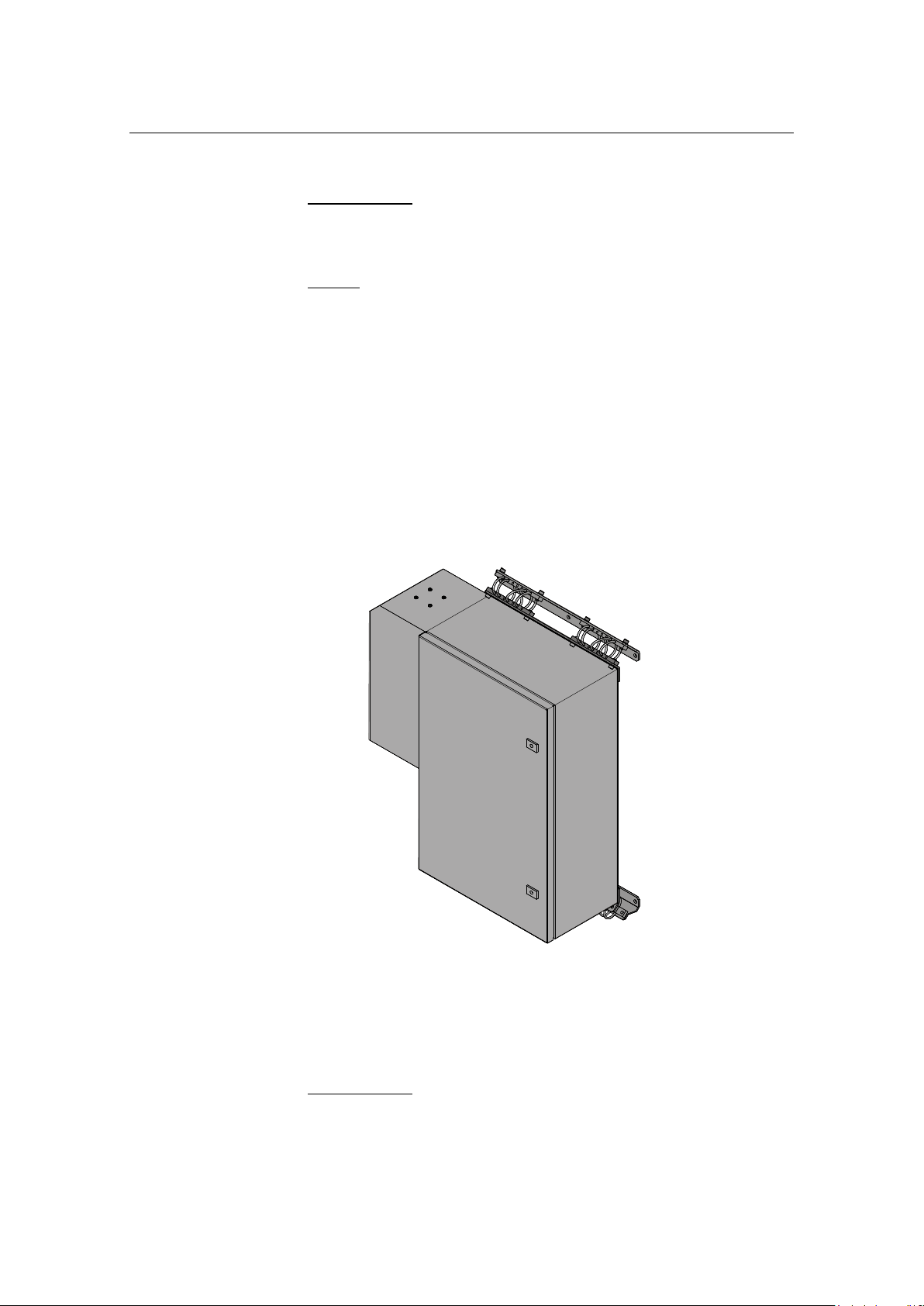
Transceiver unit Model x81 installation
Unit location
The transceiver unit (cabinet) must be located close to the hull
unit, either in the same compartment or in a compartment in the
close vicinity.
Figure 7 Cabinet mounting - side view
Logistics
Safety - Refer to the general safety procedures in the front of
this manual.
Personnel - Minimum 3 trained mechanical/electrical fitters.
Special tools - None.
Drawings - Transceiver unit Model x81 mounting drawing in
the Drawing file chapter from page 157.
303490/H 39
Page 54

HiPAP® Model 501/451/351/101
Procedure
See the procedure for installing the x81 transceiver unit with an
adapter kit on page 41.
____________________________________________________________
Note You do not need to remove the circuit boards and modules from
the cabinet during the installation process. Keep the cabinet
door closed. Ensure that the cabinet is not exposed to dust,
moisture, vibration or physical damage during the installation
process.
____________________________________________________________
Caution Check the other side of the bulkhead and decks before
welding to make sure it is safe to weld the brackets to
the bulkhead.
____________________________________________________________
The anchor bolts for the shock absorbers are screwed on to the
brackets.
1 Select a suitable bulkhead.
2 Measure and mark the locations where the shock absorber
brackets (with bolts) are to be mounted.
3 Remove the brackets from the shock absorbers by
removing the 16 nuts (four for each shock absorber).
- There is no need to remove the shock absorbers from
the cabinet.
4 Weld the brackets to the bulkhead.
5 Clean the welds and brackets, and paint them with the
appropriate preservation mediums.
6 Once the paint is dry, lift the cabinet into position and
align the shock absorbers onto the bracket bolts.
7 Start with the upper shock absorber, and bolt the shock
absorbers to the brackets.
____________________________________________________________
Warning Ensure that all the power supplies are switched
off and the fuses removed before you connect the
cables.
____________________________________________________________
40 303490/H
Page 55

Power
If you only have 110 Vac power available, an external
transformer from 110 Vac to 230 Vac must be installed on the
main power line to the transceiver unit.
Mounting
1 Open the unit.
- Inside the unit there are four through holes for the
mounting screws, one in each corner.
- Mounting screws w/nuts are not included.
2 Mount the unit where suitable.
3 Fasten the four mounting screws.
4 Close the unit.
Cabling
Installation
Ensure that enough excess cable is provided to allow the units to
be moved around during maintenance.
1 Open the door
How to open/close the door on page 83.
2 Connect the cables
See drawings in the Drawing file chapter from page 157.
Cables - see Cables starting on page 46.
3 Once all the cables have been connected and the
installation has been checked, remove all “foreign” matter
from the cabinet and close the door.
4 Check the supply voltages and all cable connections
before applying power to the system.
____________________________________________________________
Note Several of the cables are delivered with the units. Connectors
and pin allocations for these cables are given in this document
for reference only.
____________________________________________________________
Adapter Kit for x81 Transceiver
The adapter kit is used to install the x81 transceiver cabinet in
the same place where the old HiPAP® 500 transceiver cabinet
was previously installed.
303490/H 41
Page 56

HiPAP® Model 501/451/351/101
(Cd31072a)
See drawing in the Drawing file chapter on page 185.
Procedure
1 Remove the HiPAP® 500 transceiver cabinet from the
brackets.
- The parts where the adapter kit is installed onto are
2 Fasten the top bracket with three (3) mounting screws to the
bracket where the shock absorbers are.
3 The place the plates/brackets onto the welded parts and fasten
six (6) mounting screws on the top bracket and six (6)
mounting screws on the bottom bracket.
- Make sure all the screws are fastened properly and
Transceiver unit Model x21 installation
welded into the wall.
the transceiver unit is safely mounted.
Unit location
The transceiver unit cabinet must be located close to the hull
unit, either in the same compartment or in a compartment in the
close vicinity.
Figure 8 Cabinet mounting - side view
42 303490/H
Page 57

Installation
Logistics
Safety - Refer to the general safety procedures in the front of
this manual.
Personnel - Minimum 3 trained mechanical/electrical fitters.
Special tools - None.
Drawings - Transceiver unit Model x21 mounting drawing in
the Drawing file chapter from page 157.
Procedure
____________________________________________________________
Note You do not need to remove the circuit boards and modules from
the cabinet during the installation process. Keep the cabinet
door firmly shut. Ensure that the cabinet is not exposed to dust,
moisture, vibration or physical damage during the installation
process.
____________________________________________________________
Caution Check the other side of the bulkhead and decks before
welding to make sure it is safe to weld the brackets to
the bulkhead.
____________________________________________________________
The anchor bolts for the shock absorbers are screwed on to the
brackets.
1 Select a suitable bulkhead.
2 Measure and mark the locations where the shock absorber
brackets (with bolts) are to be mounted.
3 Remove the brackets from the shock absorbers by
removing the nuts and bolts, four for each shock absorber.
- There is no need to remove the shock absorbers from
the cabinet.
4 Weld the brackets to the bulkhead.
5 Clean the welds and brackets, and paint them with the
appropriate preservation mediums.
6 Once the paint is dry, lift the cabinet into position and
align the shock absorbers onto the bracket bolts.
7 Start with the upper shock absorber, and bolt the shock
absorbers to the brackets.
303490/H 43
Page 58

HiPAP® Model 501/451/351/101
If you only have 110 Vac power available, an external
transformer from 110 Vac to 230 Vac must be installed on the
main power line to the transceiver unit.
Mounting
1 Open the unit.
- Inside the unit there are four through holes for the
mounting screws, one in each corner.
- Mounting screws w/nuts are not included.
2 Mount the unit where suitable.
3 Fasten the four mounting screws.
4 Close the unit.
- Use shake-proof washers, and tighten the nuts to an
appropriate torque.
- Ensure the correct nuts and washers are used.
____________________________________________________________
Warning Ensure that all the power supplies are switched
off and the fuses removed before attempting to
connect the cables.
____________________________________________________________
Power
Cabling
Ensure that enough excess cable is provided to allow the units to
be moved around during maintenance.
1 Connect the cables.
See drawings in the Drawing file chapter from page 157.
Cables - see Cables starting on page 46.
2 Once all the cables have been connected and the
installation has been checked, remove all “foreign” matter
from the cabinet and close the door.
3 Connect the standard cables between the various internal
units.
4 Perform the remaining cable interconnections.
5 Check the supply voltages and all cable connections
____________________________________________________________
before applying power to the system.
44 303490/H
Page 59

Installation
Note Cables are delivered with the units. Connectors and pin
allocations for these cables are given in this document for
reference only.
____________________________________________________________
303490/H 45
Page 60

HiPAP® Model 501/451/351/101
5 CABLES
This chapter provides basic information and general installation
requirements for cables. It also includes information about
transceiver units internal cabling.
For more information about all cables see separate
document Cable plan and interconnections KM Doc No.
325840.
____________________________________________________________
Note All cable connections must be made in accordance with the
guidelines laid down by the vessel’s classification society.
____________________________________________________________
If no such guidelines exist, Kongsberg Maritime recommends
that the Det Norske Veritas (DNV) Report No. 80-P008,
“Guidelines for Installation and Proposal for Test of
Equipment” be used as a guide.
Topics
Cable gland assembly procedure on page 47
Basic cable requirements on page 49
Cable planning on page 52
Computer on page 52
GPS input signals connections on page 54
1PPS converter (option) on page 54
Transceiver unit Model x81 on page 56
Transceiver unit Model x21 on page 61
Transducer to transceiver unit cables installation on page 64
Fibre-optic cable installation on page 66
Related topics
Cable plan and interconnections on page 189
Drawings in the Drawing file chapter from page 158
46 303490/H
Page 61

Installation
Cable gland assembly procedure
Cable glands are used whenever a cable passes through a watertight bulkhead or into a cabinet, to seal the opening through
which the cable passes and to protect the cable from abrasion on
the edges of the hole. Follow the guidelines detailed here when
installing cables through cable glands.
____________________________________________________________
Note There are many different types of cable gland on the market.
This procedure describes the types used (now and previously) as
standard in the units manufactured by Kongsberg Maritime. The
cable glands are not supplied with the system.
____________________________________________________________
Even though the cabinets from Kongsberg Maritime may be
prepared for specific types, the installation yard will be
responsible for selecting cable gland types and installing them.
General procedure
1 Ensure all the cables to be connected are completely
isolated from any power sources.
- This is done by; Switch off and remove the supply
fuses from any units or systems into which the
cables are already connected.
2 Select the cable to be connected into the cabinet, and
select the cable gland through which the cable is to pass.
____________________________________________________________
Note A minimum of 5 cm (recommended 5 - 10 cm) of slack cable
must be allowed, both inside and outside the cabinet, when
installing cables. This is to allow for vibration damping,
maintenance and measurement errors. Always double-check
your measurements before taking any irreversible actions.
____________________________________________________________
3 Depending on whether the cable has already been installed
in conduits, either.
a (installed) measure the maximum length of cable
required to reach from the final cable clip outside the
cabinet to the terminal blocks inside the cabinet, add 20
cm, then remove the excess cable,
303490/H 47
Page 62

HiPAP® Model 501/451/351/101
or:
b (loose cable) measure the maximum length of wire
required to reach from the cable gland to the terminal
blocks inside the cabinet, add 20 cm and mark the
cable.
____________________________________________________________
Note The cable’s outer insulation will extend into the cable gland to a
point approximately 5 mm outside the outer surface of the
cabinet wall into which the cable gland is secured.
____________________________________________________________
4 Taking care not to damage the screening, carefully remove
the outer insulation from the required cable length.
5 Leaving an appropriate length of the screen exposed from
the insulation, cut off the remainder.
Securing and terminating the cables
1 Ensure that there is 5 to 10 cm slack cable inside the
cabinet - see wiring diagram.
2 Prepare and connect the cable cores to the appropriate
terminals within the cabinet.
3 Secure the cable within the cabinet using cable clips.
4 Check the terminal connections against the wiring
diagram to ensure they are correct.
5 Follow the same procedure for all the cables and cable
glands.
Once all the cables have been fitted and checked:
6 Check the cabinet to ensure all tools and rubbish are
removed.
7 Close the cabinet door.
8 Once all the system cables are connected and checked:
9 Take the appropriate safety measures, then replace the
fuses and apply power to the system.
10 Perform a system test to ensure the installation has been
conducted successfully.
48 303490/H
Page 63

Basic cable requirements
Cable trays
All permanently installed cables associated with the system
must be supported and protected along their entire lengths using
conduits and/or cable trays.
Fibre-optic cables are described in a separate section.
Fibre-optic cable installation information on page 66
The only exception to this rule is over the final short distance
(max. 0.5 m) as the cables run into the cabinets/units to which
they are connected. These short service loops are to allow the
cabinets to move on their shock mounts, and to allow
maintenance and repair.
Wherever possible, cable trays must be straight, accessible
and placed so as to avoid possible contamination by
condensation and dripping liquids (oil, etc.). They must be
installed away from sources of heat, and must be protected
against physical damage. Suitable shields must be provided
where cables are installed in the vicinity of heat sources.
Installation
Unless it is absolutely unavoidable, cables should not be
installed across the vessel’s expansion joints. If the situation
is unavoidable, a loop of cable having a length proportional
to the possible expansion of the joint must be provided. The
minimum internal radius of the loop must be at least twelve
times the external diameter of the cable.
Where a service requires duplicate supply lines, the cables
must follow separate paths through the vessel whenever
possible.
Signal cables must not be installed in the same cable tray or
conduit as high-power cables.
Cables containing insulation materials with different
maximum-rated conductor temperatures should not be
bunched together (that is, in a common clip, gland, conduit or
duct). When this is impractical, the cables must be carefully
arranged such that the maximum temperature expected in any
cable in the group is within the specifications of the lowestrated cable.
Cables with protective coverings which may damage other
cables should not be grouped with other cables.
303490/H 49
Page 64

HiPAP® Model 501/451/351/101
Cables having a copper sheath or braiding must be installed
in such a way that galvanic corrosion by contact with other
metals is prevented.
To allow for future expansion of the system, all cables
should be allocated spare conductor pairs. Also, space within
the vessel should be set aside for the installation of extra
cables.
Radio Frequency interference
All cables that are to be permanently installed within 9 m (30
ft) of any source of Radio Frequency (RF) interference such as a
transmitter aerial system or radio transmitters, must, unless
shielded by a metal deck or bulkhead, be adequately screened by
sheathing, braiding or other suitable material. In such a situation
flexible cables should be screened wherever possible.
It is important that cables, other than those supplying services to
the equipment installed in a radio room, are not installed through
a radio room, high power switch gear or other potential sources
of interference. Cables which must pass through a radio room
must be screened by a continuous metal conduit or trunking
which must be bonded to the screening of the radio room at its
points of entry and exit.
Physical protection
Cables exposed to the risk of physical damage must be enclosed
in a steel conduit or protected by a metal casing unless the
cable’s covering (e.g. armour or sheath) is sufficient to protect it
from the damage risk.
Cables exposed to an exceptional risk of mechanical damage
(for example in holds, storage-spaces and cargo-spaces) must be
protected by a suitable casing or conduit, even when armoured,
if the cable covering does not guarantee sufficient protection for
the cables.
Metallic materials used for the physical protection of cables
must be suitably protected against corrosion.
Grounding
All metallic cable coverings (armour, metallic sheathing etc.)
must be electrically connected to the vessel's hull at both ends
except in the case of final sub-circuits where they should be
connected at the supply end only.
50 303490/H
Page 65

Installation
Grounding connections should be made using a conductor which
has a cross-sectional area appropriate for the current rating of
the cable, or with a metal clamp which grips the metallic
covering of the cable and is bonded to the hull of the vessel.
These cable coverings may also be grounded by means of glands
specially intended for this purpose and designed to ensure a
good ground connection. The glands used must be firmly
attached to, and in good electrical contact with, a metal structure
grounded in accordance with these recommendations.
Electrical continuity must be ensured along the entire length of
all cable coverings, particularly at joints and splices. In no case
should the shielding of cables be used as the only means of
grounding cables or units.
Metallic casings, pipes and conduits must be grounded, and
when fitted with joints these must be mechanically and
electrically grounded locally.
Cable connections
All cable connections are shown on the applicable cable plan
and interconnection diagrams.
Where the cable plan shows cable connections outside an
equipment box outline, the connections are to be made to a plug
or socket which matches the plug or socket on that particular
item of equipment.
Where two cables are connected in series via a junction box or
terminal block, the screens of both cables must be connected
together but not grounded.
Cable terminations
Care must be taken to ensure that the correct terminations are
used for all cable conductors, especially those that are to be
connected to terminal blocks. In this case, crimped sleeveterminations must be fitted to prevent the conductor core from
fraying and making a bad connection with the terminal block. It
is also of the utmost importance that where crimped
terminations are used, the correct size of crimp and crimping
tool are used. In addition, each cable conductor must have a
minimum of 15 cm slack (service loop) left before its
termination is fitted.
303490/H 51
Page 66

HiPAP® Model 501/451/351/101
Cable identification
Cable identification codes corresponding to the cable number
shown in the cable plan must be attached to each of the external
cables. These identification codes should be positioned on the
cable in such a way that they are readily visible after all panels
have been fitted. In addition, each cable conductor should be
marked with the terminal board number or socket to which it is
connected.
Cable planning
All cables must be available at the units, properly installed in
cable ducting.
____________________________________________________________
Note Special system requirements, adaptations or components may
introduce special drawings and cables.
____________________________________________________________
Caution All power must be switched off prior to the cable
installation.
____________________________________________________________
Caution Do not to exceed the physical limitations of the cables.
____________________________________________________________
Note In order to meet the EMC requirements, dedicated grounding
cables have been used to connect the various system units to the
vessel’s ground. These cables are identified as “X” on the cable
plan drawings. The braided grounding cable required is
supplied with the system. These cables must not be longer than 1
metre.
____________________________________________________________
Computer
Computer connections
All connections to and from the computer are made on the rear
of the unit.
A: VHDC1-68 connector, PORT 1 to 8 for serial line cable
(split cable; W-U010a,… W-U010h).
52 303490/H
Page 67

Installation
The split cable on page 171
Ethernet connectors for NET A and Net B
Ethernet connector - connection to the transceiver unit
USB ports
B: HDMI connector to display
D: VGA connector for display
Trackball (mouse)
Keyboard PS/2 style connector
C: Power input
The computer rear panel may look like the following figure:
Figure 9 Computer rear panel
Computer Dual Net connection
The computer connections for Dual Net are done via two
connectors as follows:
NET A
The RJ45 connector from NET A is connected to the Main
Net A.
NET B
If dual net is used, the RJ45 connector from NET B is
connected to the Main Net B.
Cable details see Drawing file chapter on page 157.
Depending on the Main Net implementation, the RJ45 connector
could be connected directly to a HUB or a Patch panel.
303490/H 53
Page 68

HiPAP® Model 501/451/351/101
RS-232 Data
Pin 2 PORT computer
I PPS Pulse*
Pin 8 PORT computer
Ground ref.
Pin 5 PORT computer
any PORT for RS-232 may be used.
(Cd5464)
GPS input signals connections
The signal from the GPS is normally a RS-232 serial line
transmitting NMEA serial data, and a TTL pulse once pr. second
to synchronise the computer internal timing clock to the GPS
clock.
This connection is normally done as follows:
____________________________________________________________
Note *The 1PPS pulse can have different pulse length and polarity
from different suppliers of GPS receivers, so the connection
described above will not always work. A 1PPS converter can be
used to handle the problem.
____________________________________________________________
1PPS converter (option)
This converter passes the RS-232 Data through but shapes the
1PPS pulse to a fixed pulse length and converts it from TTL
level to RS-232 level.
Figure 10 1PPS converter connections
A 9-pin D-connector extension cable is delivered with the
converter so it can be mounted where the computer is mounted.
The converter needs an external power of 9-15VDC 100 mA.
54 303490/H
Page 69

Installation
Pos Edge trig
Neg Edge trig
ST16 ON
ST15 OFF
ST14 ON
ST17 OFF
ST16 OFF
ST15 ON
ST14 OFF
ST17 ON
ST3 = Connect Data RX (Normally connected)
to 9 Pin D-SUB Pin 2
ST4 = Connect Data TX (Normally connected)
to 9 Pin D-SUB Pin 3
ST7 = Connect 422A+ (Normally open)
to 9 Pin D-SUB Pin 9
ST2 = Connect 422A (Normally open)
to 9 Pin D-SUB Pin 6
ST6 = Connect 422B (Normally open)
to 9 Pin D-SUB Pin 4
ST1 = Connect 422B+ (Normally open)
to 9 Pin D-SUB Pin 1
ST8 = Select Length A pulse (Normally open)
to RS-422 Converter
ST9 = Select Length B pulse (Normally open)
to RS-422 Converter
ST5 = Connect 1PPS (Normally connected)
to 9 Pin D-SUB Pin 8
If the distance between the GPS receiver and the computer is
more than 10 m, we advice you to mount the 1PPS converter
close to the GPS receiver.
1PPS converter internal
The 1PPS converter contains 2 DIP switch blocks.
ST14, ST15, ST16, ST17 controls the edge triggering of the
1PPS pulse.
ST13 = NEG RS-232 PULSE TERMINAL 9
ST12 = POS RS-232 PULSE TERMINAL 9
ST10 = NEG RS-232 PULSE 9 Pin D-SUB Pin 8
ST11 = POS RS-232 PULSE 9 Pin D-SUB Pin 8
303490/H 55
Page 70

HiPAP® Model 501/451/351/101
U3
P3
C4
S.NO.
ST13
ST12
ST11
ST10
ST14
ST17
ST15
U4
C2
R4
C3
ST16
C1
R1
R2
R3
U2
ST8
ST5
ST9
P2
ST1
ST2
ST6
ST4
ST7
ST3
1
1
Note:
All measurements are in mm.
The drawing is not in scale.
56 303490/H
Page 71

Cables
System cables
From the computer patch cable - see figure on page 58.
Transducer
cables
The cables pass through the base of the unit.
See drawings in the Drawing file chapter on page 157 and description
in section Transducer patch cable on page 59.
Power cable
The power cable connects to the power socket at the base of the unit.
Use the strain relief cup(s) supplied with the unit.
Power sockets w/strain relief cups
(Cd31135)
Note! For redundant power input, both power sockets must be used.
(Use power from different power sources.)
Transceiver unit Model x81
Wiring diagram on page 181
____________________________________________________________
Caution Ensure that 10 cm of slack cable is provided outside the
cabinet to allow the cabinet to move on its shock
absorbers without damaging the cable.
____________________________________________________________
Model x81 internal cabling
Model x81 power cable
303490/H 57
Page 72

HiPAP® Model 501/451/351/101
Model x81, fibre-optic cables
Figure 11 Transceiver unit Model x81 - internal
The figure shows the fibre patch cables going from the fibre
splice box to the Etherenet switch/Converter. The system fibre
cables (not shown) are termineated on the inside of the fibre
splice box.
Model x81 - transducer cable connection
This unit can connect to the transducer with two different types
of cable.
Transducer patch cable
Transducer cable with plug.
Related topics
Fibre-optic cables installation on page 66
Cable plan and interconnections on page 189
58 303490/H
Page 73

Cables
Transducer patch cable
The transceiver end of the cable has a gland plate approximately
60 cm from the connectors. This plate is mounted onto the
outside lower right rear corner of the transceiver cabinet with six
(6) mounting screws.
See cable drawings in the Drawing file chapter from page 157.
Once the gland plate has been fastened to the cabinet, the 2-8
cables (depending on configuration) should be strapped to the
double row of cable tie mounting-plates at the lower left back
wall of the cabinet, as shown in the figure on page 60. This will
provide strain relief and positioning for the cables.
It is important to fasten the cables in the correct order, to avoid
confusion when connecting the individual cables to the
electronics (filter boards).
Transducer cable with plug
This is to be used if your installations have transducer cable with
plug - typically if you are replacing the transceiver cabinet in an
existing installation. In this case, you need a TD plug conversion
kit.
TD plug conversion kit on page 112
The transducer cable attaches to the x81 cabinet, in exactly the
same way as it was attached to the “old style”, but at the bottom
of the cabinet.
Cables connection to filter boards
Connect the cables to the Filter boards in the correct order. The
cables are labelled as shown in the following figure on page 60.
Cable 0 to Filter board 0, Cable 1 to Filter board 1, ...... Cable 7
to Filter board 7.
The correct order is indicated in the figure on page 82.
303490/H 59
Page 74

HiPAP® Model 501/451/351/101
Each transducer cable
is labeled as shown
PCB rack rear side
Back wall of
the cabinet
(Cd31102)
Figure 12 Transducer cable with plug inside the cabinet
Inside the cabinet - fasten the cables as described on page 58.
60 303490/H
Page 75

Cables
System cables
From the computer patch cable - see figure on page 62
Transducer
cables
See cable drawings in the Drawing file chapter from page 157.
Power cable
The power cable connects to the power socket w/ strain relief cup at
the base of the unit - see figure on page 93.
Transceiver unit Model x21
Wiring diagram on pages 182 and 183
____________________________________________________________
Caution Ensure that 10 cm of slack cable is provided outside the
cabinet to allow the cabinet to move on its shock
absorbers without damaging the cable.
____________________________________________________________
Model x21 internal cabling
Model x21 power cable
303490/H 61
Page 76

HiPAP® Model 501/451/351/101
Model x21, fibre-optic cables
Figure 13 Transceiver unit Model x21, fibre-optical cables
The figure shows the fibre patch cables going from the fibre
splice box to the Etherenet switch/Converter. The system fibre
cables (not shown) are termineated on the inside of the fibre
splice box.
Related topics
Fibre-optic cables installation on page 66
Cable plan and interconnections on page 189
62 303490/H
Page 77

Cables
Hull unit connector
Junction box
Tranducer cables
from transceiver unit
(Cd31137)
Model x21 - transducer cable connection
This unit can connect to the transducer with two different types
of cable.
Transducer patch cable
Transducer cable with plug.
Transducer patch cable
The transceiver end of the cable has a gland plate approximately
60 cm from the connectors. This plate is mounted onto the lower
right rear corner on the outside of the transceiver cabinet with
six (6) mounting screws.
See cable drawings in the Drawing file chapter from page 157.
Transducer cable with plug
This cable is used if your installation has a transducer cable with
plug - typically if you are replacing the transceiver cabinet in an
existing installation.
A junction box is available for connecting old hull units to
HiPAP® 351/101 Transceiver unit Model x21.
Junction box kit on page 113
Figure 14 Junction box for connecting an old hull unit to Model x21
303490/H 63
Page 78

HiPAP® Model 501/451/351/101
How to connect the junction box
This is shown on drawing 304969 on pages 185 and 187
This junction box can receive the hull unit connector from
either:
a HiPAP® 501 system; sixteen (16) 37 pin D-sub connectors
this option may be used if you want to change a HiPAP®
501 system to a 351 system, by replacing the 500
transducer with a 350 transducer, and keeping the existing
hull unit.
or
a HiPAP® 351 system; three (3) 37 pin D-sub connectors.
Two cables are going out of the junction box through nipples at
the bottom, to the bottom plate of the Transceiver unit and to the
two (2) connectors connected to the filter boards inside the
Transceiver unit Model x21.
Transducer to transceiver unit cables installation
Cable information
Cabling from transducer to transceiver is separated in two parts .
One part is protected inside the hull unit and goes from the
transducer to the junction box.
The other part goes from the junction box to the
transceiver, and is the moving part of the transducer cable.
Then it is possible to replace this part if damaged, or when
connecting to another transceiver type.
The cabling from the transducer to the junction box is
standard for all transceiver types. It is made bye eight (8) round
flat cables placed and protected inside the hull unit.
See drawing on page 179 and 180
Page 1 (on page 179) shows the 8 cables and the location in the
hull unit.
The cable used is a 64 conductor round flat cable with a
common shield and insulated protection. The cable diameter is
13 mm.
64 303490/H
Page 79

Cables
Each cable is split in 2 at the transducer end. Each half goes to a
37 pin D-sub connector (not all pins are used). The other end of
the cable goes into the junction box and is terminated in a 64 pin
flat cable connector.
Page 2 (on page 180) shows one of the cables inside the hull
unit in more detail.
Example:
P501 and P502 is connected at the transducer end and to J1 in
the junction box.
P503 and P504 goes to J2 ……
HiPAP® 501/451
Cable details see drawing on page 173 and 174.
All 8 cables going into the junction box are connected to the
transceiver with the same type of cable as inside the hull unit.
Page 1 (on page 173) gives an overview of all 8 cables.
Page 2 (on page 174) shows the internal connection for every
individual cable.
HiPAP® 351/101 (x81)
Cable details see drawing on pages 175 and 176.
Just 2 cables are used from the junction box to the transceiver
unit with the same type of cable as inside the hull unit.
Page 1 (on page 175) gives an overview of the 2 cables.
Page 2 (on page 176) shows the internal connection for every
individual cable.
Note that one of the cables is split into 2 connectors in the
junction box.
HiPAP® 351/101 (x21)
Cable details see drawing on pages 177 and 178.
Just 2 cables are used from the junction box to the transceiver
with the same type of cable as inside the hull unit.
Page 1 (on page 177) gives an overview of the 2 cables.
Page 2 (on page 178) shows the internal connection for every
individual cable. Note that one of the cables is split into 2
connectors in the junction box.
303490/H 65
Page 80

HiPAP® Model 501/451/351/101
Fibre-optic cable installation
This section describes how to install fibre-optic cables and
connectors for Kongsberg Maritime computer network onboard
vessels and rigs.
____________________________________________________________
Warning During transport, cable laying and pulling into the
protective conduit, the cables must not be sharply
bent with a radius lower than the recommended
values or twisted in any way. The cable must only
be pushed/pulled by hand and not by machine.
See technical specifications for minimum allowed
bending radius.
____________________________________________________________
Related topics
Fibre-optic cable description on page 28
Cable plan and interconnections on page 189
Installation
Each fibre cable contains (4-6) fibres. A fibre link uses two
fibres, one for transmitting and one for receiving data. The
remaining fibres are spare.
The signals from a field cable source (TX) is connected to (RX)
input of Fibre-optic Converter and vice versa.
Maximum cable length
The maximum Gigabyte Ethernet distance for point-to-point
links is 1000 m (850 nm) or 600 m (1310 nm) cable length when
using a standard multi mode cable.
Note Single mode cables should be used if a longer distance is
required. If this is the case then the receiver and the transmitter
in the switches in both ends have to be changed to single mode
type. Maximum distance for point-to-point links with single
mode cables depends on cable type used.
66 303490/H
Page 81

Cables
Cable routing and protection recommendations
The fibre-optic cable can be laid together with all types of other
cables.
For mechanical protection in harsh environments the
network cables should be laid in a protective conduit, e.g.
aluminium conduit, galvanised-steel conduit or flexible
metallic conduit Pg-21.
Where cables are laid on the floor, e.g. just before entry into
a cabinet, cable trays must be used in order to prevent the
possibility of physical damage being caused by personnel
accidentally stepping on the cables.
The fibre-optic cable should have a sufficient slack in both
ends to allow installation and termination inside the network
distribution unit.
Cable termination
ST connectors are used for connecting fibre-optic network
cables to the fibre splice box (in the transceiver unit).
Terminating fibre-optic cables
Fibre-optic cables should ideally be delivered in required length
ready with ST connectors in both ends.
____________________________________________________________
Note The termination of fibre connector’s work must be done by
experienced personnel only.
____________________________________________________________
A patch cable (ST to LC) is used from the fibre splice box to the
switch/converter.
Each fibre has to be tested for reflections and damping (loss).
The test results must be documented.
Cable screen
If the fibre-cable is screened/armoured the screen/armour must
be terminated in EMC cable glands. If the cable has no
screen/armour, standard cable glands can be used.
303490/H 67
Page 82

HiPAP® Model 501/451/351/101
The outer cable screen, if applicable, is to be grounded in both
ends. Grounding is done by means of shielded cable glands or
EMC Mats at the point of entry into the console/cabinet. Inner
cable screen(s), if applicable, is to be terminated together with
the outer screen.
68 303490/H
Page 83

6 OPERATION
HiPAP® operation
Operation of the HiPAP® system:
See the APOS for HiPAP® 501/451/351/101 Instruction Manual
and the APOS online help.
Operation
303490/H 69
Page 84

HiPAP® Model 501/451/351/101
7 MAINTENANCE
See the MP8200 Maintenance Manual, doc no. 366813.
This chapter contains information on how to perform all normal
preventive and corrective maintenance on the standard HiPAP®
system units.
The procedures are identical for all HiPAP® systems.
The technical descriptions included in this manual are
intended to be used by maintenance technician and/or
engineer, with experience of computer-based electronic
circuitry. It is also strongly recommended that the personnel
are familiar with the basic principles of hydro-acoustic
technology, and in particular, positioning systems.
The maintenance personnel are expected to replace faulty
Line Replaceable Units (LRUs) (circuit boards or modules),
but not to perform circuit board repairs. In order to find the
faulty component, it is also expected that the maintenance
personnel have access to standard electronic instruments,
such as oscilloscopes and MultiMate’s.
____________________________________________________________
Note If your organization (or vessel/rig) does not have the
appropriate personnel available, you are strongly advised to
contact either Kongsberg Maritime or your dealer for
assistance.
____________________________________________________________
Warning Kongsberg Maritime accepts no responsibility for
any damage or injury to the system, ship or
personnel caused by drawings, instructions and
procedures not prepared by Kongsberg Maritime.
____________________________________________________________
This manual does not describe the maintenance of the peripheral
devices (printers, plotters and sensors). For information about
these items, refer to the applicable manufacturer’s
documentation.
70 303490/H
Page 85

Topics
Safety on page 71
Before you start on page 72
Maintenance philosophy on page 72
Maintenance schedule on page 74
Preventive maintenance on page 74
Related topics
Backup on page 2
Software upgrade on page 2
Tools on page 34
Spare parts on page 110
Maintenance
Drawings in the Drawing file chapter from page 157
Safety
Refer to standard company/vessel safety procedures before
commencing maintenance work.
See also High voltage safety warning on page II in this manual.
____________________________________________________________
Note After any maintenance work, the system must be checked to
ensure it works correctly. Refer to the procedure in the Test and
alignment procedures.
____________________________________________________________
303490/H 71
Page 86

HiPAP® Model 501/451/351/101
Before you start
Before you start performing any maintenance, the power
must be switched off, and it must be kept off while the
maintenance is being carried out.
____________________________________________________________
Warning The maintenance engineer MUST wear a
grounding bracelet, which is securely connected
to the vessel’s ground, at all times when
performing maintenance on the units.
____________________________________________________________
1 Switch off all power to the HiPAP® system, and to other
systems connected to the HiPAP® (Motion sensor,
Heading sensor etc.).
2 Remove the fuses if possible (for the other systems) and
label the fuse panels with tags stating that maintenance is
being carried out on the system.
Maintenance philosophy
The maintenance philosophy recommended by Kongsberg
Maritime is:
On-board maintenance should be carried out by a
maintenance engineer, with the assistance of the operator.
The maintenance should include the following:
Calibrations
Simulations
Functional tests
Traditional troubleshooting based on a good knowledge of
the system.
Replacement of faulty parts should be limited to the line
replaceable units (LRUs) recommended in the spare parts list.
72 303490/H
Page 87

Maintenance
____________________________________________________________
Note To reduce the number of spare boards required, standard circuit
boards without software may be provided. In the event of a
replacement becoming necessary, the software on the faulty
circuit board must then be transferred to the new board. Any
links and switches on the new circuit board must also be set as
on the old board.
____________________________________________________________
Whenever a faulty unit has been replaced, the unserviceable unit
should be sent to Kongsberg Maritime, or an appointed dealer,
for repair.
Error detection
If a fault is detected, the operator should call the maintenance
engineer at the earliest opportunity. The operator should be
issued with a standard procedure detailing how he/she is to
respond to system errors or faults. This procedure should
contain the following (as a minimum):
Whenever an error message appears:
Write down any Alarm message.
Write down the parameters currently set in the system.
Write down a brief description of the actions currently being
carried out.
Write down the commands being executed (if any) when the
error appeared.
Write down the controls carried out (if any) when the error
message appeared.
Write down any other information that might be valuable to
the maintenance engineer during troubleshooting. This also
includes events not directly connected to the system (for
example bad weather, excessive temperature in operations
room etc.).
Verification
The first action to be performed by the maintenance engineer on
receipt of a fault message must be fault verification. If the
system has been closed down, it should be powered up again
(unless the fault has caused serious damage to the system), and
an attempt made to make the fault reappear.
303490/H 73
Page 88

HiPAP® Model 501/451/351/101
Unit
Weekly
1-3 Month
6 Months
Reference
All units - exterior
Clean
-
Check
All cable connections
- - Check
Verify the fault during continued operation.
Maintenance schedule
Maintenance routines must be performed regularly and
effectively to ensure that the equipment is kept in top condition.
The chart below states the maximum recommended intervals at
which the various routines should be performed - the intervals
should be decreased if the system is used excessively.
Maintenance chart
Preventive maintenance
The preventive maintenance consists of keeping the units clean.
Use:
Soft lint-free cloth
Bucket
Mild liquid detergent
Wet the cloth, then wring as much of the water out as possible.
____________________________________________________________
Note Use only a damp cloth - so there is no possibility of water
dripping into the unit.
____________________________________________________________
74 303490/H
Page 89

Cable plan and interconnections
8 CABLE PLAN AND INTERCONNECTIONS
Separate document; Cable plan and interconnections
doc. No 325840.
303490/H 75
Page 90

HiPAP® Model 501/451/351/101
9 SYSTEM UNITS - DETAILED DESCRIPTION
This chapter gives a detailed description of the HiPAP® system
units.
Topics
Computer on page 76
Keyboard on page 78
Trackball on page 78
1PPS converter (option) on page 78
Ethernet switch / Converter on page 78
Fibre Splice Box on page 79
Transceiver unit Model x81 on page 79
Transceiver unit Model x21 on page 91
Circuit boards and units on page 97
Computer
This section describes the internal layout and connections of the
computer parts.
Topics
Internal layout on page 77
Opening / closing the unit on page 78
See the MP8200 Maintenance Manual, doc no. 366813.
Before you start
____________________________________________________________
Note Before you start, please read the general maintenance
information on page 72.
____________________________________________________________
76 303490/H
Page 91

System units – detailed description
Computer internal
The following units and circuit boards in the computer are
defined as Line Replaceable Units (LRUs):
Computer
Bluestorm serial interface card
Power supply unit
Hard disk
DVD Recorder
The computer is based on a commercially available
motherboard, and the additional boards are standard plug-in
circuit boards.
The placement of boards and units are shown in the figure
below. The boards (not the motherboard) and units can be
replaced separately.
Figure 15 Computer - internal layout
303490/H 77
Page 92

HiPAP® Model 501/451/351/101
How to open the computer
1 Switch off the power.
2 Remove the power connector from the back of the unit.
3 Switch off power to all other units connected to the
computer (display, transceiver, motion sensor, etc).
4 Unscrew the computer from the bracket.
5 Lift the top cover by using the lever on the top.
Keyboard
Under normal conditions, maintenance is not required, apart
from keeping the unit clean. If the keyboard is not functioning
properly, the unit must be replaced.
Trackball
Under normal conditions, maintenance is not required, apart
from keeping the unit clean. If the trackball is not functioning
properly, the unit must be replaced.
1PPS converter (option)
Maintenance is not required under normal conditions apart from
keeping the unit clean. If the 1PPS converter is not functioning
properly the unit must be replaced.
1PPS converter information, see page 11
Ethernet switch/Converter
Maintenance is not required under normal conditions apart from
keeping the unit clean. If the Ethernet switch/Converter is not
functioning properly, the unit must be replaced.
Ethernet switch / Converter information, see page 11
Replacement
1 Remove all cables.
2 Replace the unit.
Replacement, see page 87
78 303490/H
Page 93

System units – detailed description
3 Reconnect all cables.
Configuration
The new Ethernet switch/Converter must be configured. You
will find the configuration information on the Operator Station.
Ref:
C:\Install\moxa\moxaconfig.rtf
Fibre Splice Box
Maintenance is not required under normal conditions apart from
keeping the unit clean.
Transceiver unit Model x81
This section describes the internal layout, connections and
replacement of the Transceiver unit Model x81 parts.
Topics
Transceiver unit Model x81 internal layout on page 80.
Replacement of parts on page 82
If more information is required, contact Kongsberg Maritime for
service.
Before you start
____________________________________________________________
Note Before you start, please read the general maintenance
information on page 72
____________________________________________________________
303490/H 79
Page 94

HiPAP® Model 501/451/351/101
TRX32 boards
-
Transmitter/Receiver board - up to eight (8) boards,
depending on the system configuration.
This is a plug-in unit.
TRX32 Filter boards
-
Transmitter/Receiver filter board - up to eight (8)
boards, depending on the system configuration.
This is a plug-in unit.
Ethernet switch / Converter
-
Ethernet to Fibre-optic converter. Dual Ethernet
possibility. Used LC fibre-optic connectors.
Fibre Splice Box
-
Fibre splice Box with up to eight (8) ports MX-WFR00024-02. This box is used to terminating the system
Ethernet fibre-optic cable. A patch cable is used from
Model x81 internal layout
Figure 16 Transceiver unit Model x81 - internal layout
The following parts contained within this transceiver unit are
defined as Line Replaceable Units (LRUs):
80 303490/H
Page 95

System units – detailed description
this box to the Ethernet switch / Converter.
Power supply PSU-Main
-
Provides the voltages required by the TRX32 boards,
and carries a “power on” indicator.
This is a plug-in unit.
Power supply PSU-48 V Dc
-
Provides power to the transmitters and carries a
“power on” indicator. This is a plug-in unit.
Fan unit
-
For air circulation inside the transceiver unit.
Terminal blocks
-
Used for connecting externally supplied signals.
Ethernet switch / Converter
power supply
-
The DR-4524 DIN-rail 24 Vdc Power Supply is used.
Cooling unit
-
This unit is mounted on the outside, on the transceiver
unit right side. It cools the air inside the transceiver
unit. “Air to air” principle.
Separate manual is supplied with the unit. This is not a
Kongsberg Maritime document.
Power sockets w/strain relief cups
(Cd31135)
Model x81 power sockets
The transceiver model x81 is equipped with two power sockets
for redundant power input. These should be connected to
different power sources. If redundant power is not used, only
one of the sockets needs to be connected. Two strain relief
cup(s) are supplied with the unit (with mounting screws).
Figure 17 Transceiver Unit Model x81 power sockets
303490/H 81
Page 96

HiPAP® Model 501/451/351/101
1 2
3
4
5 6
7
0
Fuse
behind
cover
Fan unit
PCB rack rear side
(Cd31100)
TRX32 Filter boards
Transceiver unit Model x81, PCB rack
Figure 18 Transceiver unit Model x81, PCB rack
Replacement of Model x81 parts
Topics
How to open / close the door on page 83
Replacement of the TRX32 boards on page 83
Replacement of the TRX32 filter boards on page 85
Replacement of the power modules on page 87
Replacement of the Ethernet switch / Converter on page 87
Replacement of the power unit for Ethernet switch / Converter on
page 88
Replacement of the Fibre Splice Box on page 88
Replacement of the terminal blocks on page 88
Replacement of the fans on page 87
Replacement of the fuses on page 89
If more information is required, contact Kongsberg Maritime for
service.
82 303490/H
Page 97

System units – detailed description
Before you start
____________________________________________________________
Note Before you start, please read the general maintenance
information on page 72.
____________________________________________________________
How to open / close the door
Before performing any replacements, you must open the
transceiver unit front door. To do this:
1 Loosen the four captive screws in the corners of the door.
2 Lift the door off.
To close the door, proceed in reverse order!
Circuit boards basics
TRX32 boards location, see the figure on page 80.
TRX32 filter boards location, see the figure on page 82.
The circuit boards in the transceiver unit rack are all plug-in
modules. The boards are locked into position by two ejectors.
TRX32 Transceiver board visual inspection
Refer to page 107
Replacement of a TRX32 Transceiver board
Before you start, read the following:
Before you start removing any board/unit on page 71.
How to open/close the Transceiver unit door on page 83.
Removal
1 Switch off the transceiver unit using the Main switch.
2 Locate the faulty board.
303490/H 83
Page 98

HiPAP® Model 501/451/351/101
(cd31130)
Figure 19 TRX32 Transceiver board
3 Note the locations of, and remove, any cable connected to
the front of the board.
4 Press down the red knob (A) on the board ejectors. The
ejectors are now free.
5 To loosen the board, push the top ejectors (B) up, and the
bottom ejector (B) down.
6 Then pull the board straight out (C).
7 Place the board into an anti-static plastic bag and place it
on a clean, stable work-bench where it cannot be
damaged.
Replacement
In principle, replacing a board is to perform the steps in
Removal a TRX32 board in reverse order.
1 Grab the board ejectors with both hands, and push the
board straight in.
84 303490/H
Page 99

System units – detailed description
2 Lock the board in place by pulling the top locking handle
down, and the bottom locking handle up.
3 Insert the front mounted Ethernet cable and other front
mounted cables.
4 Once all the boards are in position, re-apply power as
required.
5 Close the transceiver unit front door.
Replacement of a TRX32 filter board
Before you start, read the following:
Before you start removing any board/unit on page 71.
How to open/close the Transceiver unit door on page 83.
Removal
1 Switch off the transceiver unit using the Main switch.
2 To access the filter boards:
a Open the access door to remove a filter board.
Access door on page 13
Same principle as removing a TRX32 board, see
procedure on page 83.
or
b Removing the PCB rack.
How to remove the PCB rack, see procedure on page 86.
Replacement
In principle, replacing a power unit is to perform the steps in
paragraph Removal in reverse order.
Replacement of units
Before you start, read the following:
Before you start removing any board/unit on page 71.
How to open/close the Transceiver unit door on page 83.
Units location, see the figure on page 80.
303490/H 85
Page 100

HiPAP® Model 501/451/351/101
A
D
D
A
A
B
B
A
(Cd31095a)
C
PCB rack
Removal
The unit is mounted with four (4) screws.
Remove the module as follows:
1 Switch off the transceiver unit using the Main switch.
2 Remove the cables (C) at the front of the rack.
Figure 20 Model x81 PCB rack
3 Open the access door on the left side and disconnect the
transducer cables from the filter boards.
4 Remove the four screws (A).
5 Grab the two handles (B) and pull the rack gently out.
6 When the rack is almost pulled out, support the rack and
lift it out.
7 Place the rack on a suitable workbench.
Replacement
In principle, replacing the rack is to perform the steps in
paragraph Removal in reverse order.
86 303490/H
 Loading...