

Kongsberg 1007D Operator's Manual
Kongsberg Maritime
Operator manual
1007D
Altimeter series


974-72007001/1.0
1007D Altimeter Series
Operators manual

Document revisions
Version
1.0
Version 1.0
Date Written by Checked by Approved by
August 06, 2010 BK BC BC
- First release
Document history
About this document
The information contained in this document is subject to change without prior notice.
Kongsberg Mesotech Ltd. shall not be liable for errors contained herein, or for incidental or
consequential damages in connection with the furnishing, performance, or use of this
document.
© 2008 Kongsberg Mesotech Ltd. All rights reserved. No part of this work covered by the
copyright hereon may be reproduced or otherwise copied without prior permission from
Kongsberg Mesotech Ltd.

1007D Altimeter Operators Manual 974-72007001/1.0
Table of contents
1 GENERALDESCRIPTION....................................................................................................................1
1.1 FEATURES................................................................................................................................................1
1.2 OPTIONS.................................................................................................................................................2
1.3 INTRODUCTION.........................................................................................................................................2
2 THEORYOFOPERATION...................................................................................................................5
2.1 OPERATINGMODE....................................................................................................................................8
2.2 RANGERESOLUTION..................................................................................................................................9
2.3 OVER‐RANGECONDITION.........................................................................................................................10
2.4 RECEIVERGAINADJUSTMENT....................................................................................................................11
2.5 AUTO‐GAINADJUSTMENT.......................................................................................................................11
3 INSTALLATION................................................................................................................................13
3.1 MOUNTINGPOSITION.............................................................................................................................. 13
3.2 ELECTRICALCONNECTION.........................................................................................................................14
3.3 SYSTEMCHECKOUT.................................................................................................................................16
3.4 DEPLOYMENT.........................................................................................................................................17
3.5 MAINTENANCE.......................................................................................................................................17
4 TELEMETRY....................................................................................................................................18
4.1 808MODEMESSAGES............................................................................................................................19
4.1.1 UplinkMessages.......................................................................................................................19
4.1.2 DownlinkMessages..................................................................................................................20
4.2 809MODEMESSAGES............................................................................................................................21
4.2.1 UplinkMessages.......................................................................................................................21
4.2.2 DownlinkMessages..................................................................................................................22
5 OPTIONS........................................................................................................................................32
5.1 HARDWAREHOLD‐OFF............................................................................................................................. 32
5.2 EXTERNALSYNCHRONIZATION....................................................................................................................32
5.3 AUXILIARYSERIALOUTPUT........................................................................................................................33
5.4 ANALOGOUTPUT....................................................................................................................................33
5.5 ALTIMETERRECONFIGURATIONUTILITY........................................................................................................ 34
6 TIPSFORSUCCESSFULALTIMETRY..................................................................................................36
7 APPENDIX‐1007DALTIMETERALTITUDEDETECTIONALGORITHM.................................................38
<Registration no>/<rev> V

974-72007001/1.0 1007D Altimeter Operators Manual
<This page is left intentionally blank>
VI

1007D Altimeter Operators Manual 974-72007001/1.0
General Description Page 1
1 GENERAL DESCRIPTION
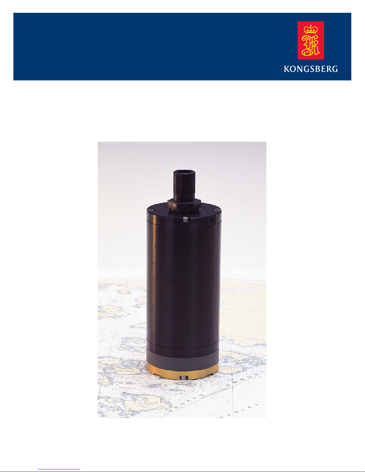
The 1007D digital altimeters are small, rugged, light-weight
instruments for deep ocean applications, where dimensions
and weight are key equipment selection factors. The 1007D is
ideally suited for applications such as positioning, berthing,
measurement of above-seabed altitude or depth below the
water surface.
1.1 Features
200 kHz transmit frequency standard (120 kHz or 675
kHz optional)
Configurable settings for operating parameters (range,
resolution, firing rate, pulse width, etc.)
Configurable settings for detection parameters (threshold,
range, return pulse width, etc.)
First or peak-level return based obstacle/bottom detection
Adjustable threshold based range measurements
User selectable range windowing control
RS485 or RS232 serial interface standard
3 basic models available - standalone analog output,
standalone digital serial output, and MS1000 mode (for
use with MS1000 system)
808, 809, or NMEA output data formats
Adjustable manual gain or automatic gain offset modes
Compatible with Kongsberg Mesotech's MS1000 PC-
based sonar imaging / data-logging software. Scope-graph
and echo sounding available when operating with
MS1000 software.
Kongsberg Mesotech Ltd.
Port Coquitlam, BC - Canada

974-72007001/1.0 1007D Altimeter Operators Manual
Page 2 General Description
1.2 Options
RS422 serial interface
analog output
electrical hold-off control
multi-head ping synchronization
second serial output for vehicle servo control
connector options (contact factory)
1.3 Introduction
The Model 1007D acoustically measures underwater altitude
at high resolution, producing a digital and/or analog output
proportional to range.
It is primarily intended for remote operation where its output
will be connected to a remote PC or MS1000 host, or to other
instrumentation such as a data acquisition system or a
telemetry system. Consequently, the 1007D does not have any
operating controls nor does it have a display.
The 1007D’s processing features, flexibility, and performance
are designed to address the requirements of many applications
and deployment scenarios. Many of its sonar acquisition and
echo verification parameters such as pulse width, receiver
gain offset, range limits, and sensitivity are all programmable.
Altitude measurements can be output via a serial interface in a
number of selectable formats for various interfacing
requirements.
Kongsberg Mesotech Ltd.
Port Coquitlam, BC - Canada

1007D Altimeter Operators Manual 974-72007001/1.0
General Description Page 3
The 1007D is capable of measuring altitude at high resolution.
A resolution of better than 2.5 millimetres can be achieved for
distances up to 38 meters. The resolution is adjustable to
allow the operator to optimize the balance between resolution
and ping rate.
In its standard stand-alone configuration, the 1007D is
connected to a remote PC or computer terminal via an RS485
or RS232 interface. Range measurements are up-linked
directly to the host computer in a number of selectable ASCII
formats and range units. Legacy Model 808 or 809 Altimeter
output formats are also available. Range measurements can
also be output to a DC voltmeter from an optional analog
interface like that found in our Model 807 Altimeters. The
voltage output is directly proportional to the range (10 volts
corresponding to maximum range).
The 1007D's programmable gain receiver is controlled by a
"Time Varying Gain" (TVG) function to compensate for
acoustic return signal losses that increase with range. This
process is microprocessor controlled and is applied during
each ping, synchronized to the start of the transmit pulse. The
TVG function is therefore very stable and accurate, and
results in a very stable output signal.
Kongsberg Mesotech Ltd.
Port Coquitlam, BC - Canada

974-72007001/1.0 1007D Altimeter Operators Manual
Page 4 General Description
The 1007D is compatible with Kongsberg Mesotech’s
MS1000 PC software and related accessories such as the
MS1000 Power Supply Box. The MS1000 software can
support up to 255 devices (sonar heads and/or 1007D
Altimeters) over a single RS485 connection. The 1007D can
also be used with the ROV Hub option on the MS1000 that
allows several 1071/1171 scanning sonars and 1007D
altimeters to be operated and synchronized with a single
ethernet cable connection. The MS1000 software displays
altitude measurements in a directly readable format in a
moveable display window. An analog scope-graph window
provides the operator with a visual indication of the aggregate
acoustic signal received each ping, plotted as graph of signalstrength vs. range.
The Model 1007D is packaged in a small rugged housing
rated for a maximum depth of 3000 meters. A single
underwater connector provides a simple cable connection to
an external DC power source, and either an external PC or a
voltmeter.
Kongsberg Mesotech Ltd.
Port Coquitlam, BC - Canada

1007D Altimeter Operators Manual 974-72007001/1.0
Theory of Operation Page 5
2 THEORY OF OPERATION
The Model 1007D altimeter measures range as a function of
the two-way acoustic travel time between its transducer and a
reflecting target or sea bottom.
The 1007D range measurement cycle (or ‘ping’) begins by
transmitting an acoustic tone burst from its transducer into a
narrow conical-shaped beam. This beam pattern depends on
the transducer element used, and defines the coverage of the
targets which will be illuminated. The acoustic energy is
reflected back to the transducer by each target at a delay time
proportional to its distance, and at a strength related to its size
and reflectivity.
The signal received by the transducer consists of a series of
pulses or “returns” corresponding to each insonified target,
and is amplified and conditioned by an adjustable gain
receiver. The receiver output is sampled, digitized, and stored
in internal memory over the duration of the ping, as
determined by the altimeter’s current maximum range setting.
The sample data is then analyzed by a Digital Signal
Processor (DSP) to determine time and distance to the most
likely target.
The receiver gain is hardware-controlled by a Time-VaryingGain (TVG) characteristic to compensate for acoustic energy
losses that increase with range:
Ro)-2a(R Log(R/Ro)20 (dB) Gain
Kongsberg Mesotech Ltd.
Port Coquitlam, BC - Canada

974-72007001/1.0 1007D Altimeter Operators Manual
Page 6 Theory of Operation
where R = range, Ro = reference range (1m), and a =
attenuation constant in dB/range units. The first term
compensates for the natural spreading loss proportional to the
inverse of the square of the distance, assuming a wide, flat,
bottom. The second term compensates for losses due to
energy absorption and is directly proportional to the distance,
assuming uniform water salinity, temperature, and pressure.
The sampled data set of the received signal may contain
numerous ‘returns’ of varying amplitudes due to noise or
representing actual targets. The DSP identifies those ‘returns’
that meet the following adjustable criteria as potential
candidates for the final range measurement:
a) minimum amplitude (threshold)
b) minimum pulse width
c) minimum inter-pulse gap width
d) minimum range
e) maximum range
Adjustments are made to these settings to reduce the detection
of spurious and/or low reflectance targets. The minimum
range setting can also be adjusted to eliminate nearby targets
such as vessel hulls, cables, etc. near the altimeter.
The range of candidate ‘returns’ in the sample data set is
estimated as the time the ‘return’ pulse first exceeds a
minimum amplitude threshold.
After the candidate ‘returns’ have been identified from the
sample data set, one is chosen by the DSP using a decision
rule that selects the sea bottom return. The operator can select
one of the following decision rules the 1007D uses to
determine the sea bottom return:
Kongsberg Mesotech Ltd.
Port Coquitlam, BC - Canada

1007D Altimeter Operators Manual 974-72007001/1.0
Theory of Operation Page 7
a) first return: The selected return is the first return whose
level is above the set threshold. This mode is
recommended for obstacle avoidance applications
b) peak return: The selected return is the strongest return
whose level is above the set threshold. This mode is
recommended for long range applications in low
multipath environments for detection of hard, flat sea
bottom.
The acoustic travel time is calculated for the chosen return
based on its position in the sample data set, then converted to
a range estimate. This estimate is then filtered using an
adjustable range window that considers the new range
estimate valid only if it is within a range window of the
previous estimate. This range window feature can be disabled
if desired.
If after each ping a valid range estimate is determined, the
range data is either up-linked as an ASCII string from the
telemetry interface and/or optionally output as a scaled 0..10V
analog output. However, if no return is detected, or if range
windowing is enabled and the range estimate of the current
ping is outside the range window of the previous ping, an
over-range value is output. This over-range value is zero from
the digital telemetry interface, and typically +10.24V from the
optional analog interface.
Kongsberg Mesotech Ltd.
Port Coquitlam, BC - Canada

974-72007001/1.0 1007D Altimeter Operators Manual
Page 8 Theory of Operation
2.1 Operating Mode
Immediately on power-up the 1007D Altimeter scans its
RS232/485 telemetry interface for the first ten seconds in
order to detect MS1000 telemetry. If successful, the altimeter
sets itself up as an MS1000 device for control by an MS1000
PC host. If no MS1000 is detected within the allotted time, the
1007D goes into its factory-configured default mode. These
modes are one of the following and are configured at the
factory as per customer requirements:
a) 807 mode: operates as a standalone instrument with an
analog output interface, where range measurements
are output continuously as a 0…10V signal only. All
range, detection, and output scaling settings are
configured at the factory as per customer
requirements. The 807 mode can only be entered as a
power-up default. While operating in this mode, the
telemetry type (RS232, RS485, or RS422) is fixed by
a factory-configured setting, and cannot be changed.
b) 808 mode: emulates a standalone Model 808
Altimeter, where range measurements are
continuously output via a quasi-full-duplex telemetry
interface (RS232, RS485, or RS422). In this mode the
altimeter accepts XON/XOFF characters from a
computer to pause/resume pinging. All range,
detection, and output scaling settings are configured at
the factory as per customer requirements. This mode
can only be entered as a power-up default. During this
mode, the telemetry type (RS232, RS485, RS422) is
fixed by a factory-configured setting, and cannot be
changed.
c) 809 mode: operates as a standalone instrument, where
range measurements are continuously output via a
quasi-full-duplex telemetry interface (RS232, RS485,
or RS422). Range, detection, and output scaling
parameters are programmable via serial commands.
This mode can only be entered as a power-up default.
Kongsberg Mesotech Ltd.
Port Coquitlam, BC - Canada

1007D Altimeter Operators Manual 974-72007001/1.0
Theory of Operation Page 9
During this mode, the telemetry type (RS232, RS485,
RS422) is fixed by a factory-configured setting, and
cannot be changed. This mode emulates the Model
809 Altimeter, providing a pin-compatible serial
interface for output/control of altitude measurements
via a computer.
d) MS1000 mode: operates as an MS1000 device over an
RS232 or RS485 telemetry interface, and is controlled
by MS1000 host software running on a PC. In this
mode, the 1007D detects the telemetry type (RS232,
RS485) used by the MS1000 host PC. RS-485
telemetry is the most flexible, allowing multiple
1007D altimeters and MS1000-compliant digital
sector scanning sonar heads to be connected to a single
cable.
The MS1000 mode can also entered from any of the
standalone 807, 808, or 809 modes if MS1000 telemetry is
detected. However, this is possible only if the altimeter is
configured for a telemetry type that agrees with that used by
the MS1000 host PC. Further details regarding 1007D setup
and control with the MS1000 software can be found in the
MS1000’s help utility or in the MS1000 Operator’s Manual.
The 807, 808, and 809 modes are collectively referred to as
the standalone 80x modes throughout this document.
2.2 Range Resolution
The 1007D altimeter is capable of resolving distance at very
high resolution, limited only by the altimeter's maximum
sampling rate (307.2kHz or 2.4mm) and sample memory size
(16000 samples). This implies that distances can be measured
down to 2.4mm resolution for maximum ranges up to 38
meters.
Kongsberg Mesotech Ltd.
Port Coquitlam, BC - Canada
 Loading...