

PEN00042-03
DUMP TRUCK
HD785
SERIAL NUMBERS
-5
4254
and up
WARNING
Unsafe Use of this machine may cause serious injury or
Death.Operators and maintenance personnel must read
this manual before operating or maintaining this machine.
This manual should be kept near the machine for
reference and periodically reviewed by all personnel
who will come into contact with it.
NOTICE
Komatsu has Operation & Mai ntenance Manuals written
in some other languages. if a foreign langu age manual
is necessary, contact your local distr ibutor for
availability.

.
1 - 1
.
FOREWORD
FOREWORD
FOREWORD
This manual provides rules and guidelines which will help you use this machine safely and effectively. The
precautions in this manual must be followed at all times when performing operation and maintenance. Most
accidents are caused by the failure to follow fundamental safety rules for the operation and maintenance of
machines. Accidents can be prevented by knowing beforehand conditions that may cause a hazard when
performing operation and maintenance.
WARNING
Operators and maintenance personnel must always do as follows before beginning operation or maintenance.
Always be sure to read and understand this manual thoroughly before performing operation and maintenance.
Read the safety messages given in this manual and the safety labels affixed to the machine thoroughly and be sure that you
understand them fully.
Keep this manual in the storage location for the operation and maintenance manual given below, and have all personnel read it
periodically.
If this manual has been lost or has become dirty and cannot be read, request a replacement manual immediately from Komatsu
or your Komatsu distributor.
If you sell the machine, be sure to give this manual to the new owners together with the machine.
Komatsu deliversmachines that comply with all applicable regulations and standards of the country to which it has been shipped.
If this machine has been purchased in another country or purchased from someone in another country, it may lack certain safety
devices and specifications that are necessary for use in your country. If there is any question about whether your product
complies with the applicable standards and regulations of your country, consult Komatsu or your Komatsu distributor before
operating the machine.
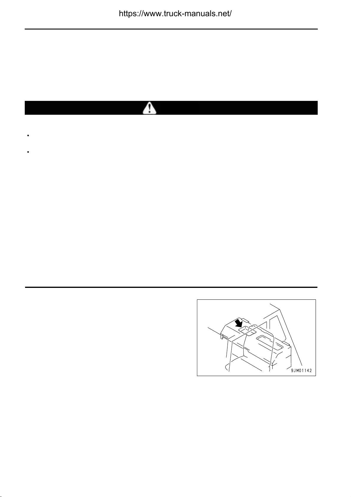
Place to Keep the Manual
It is located behind the operator's seat.
1 - 2
.
FOREWORD
FOREWORD
1 - 3
.
FOREWORD
FOREWORD
1 - 4
.
FOREWORD
SAFETY INFORMATION
SAFETY INFORMATION
To enable you to use this machine safely, safety precautions and labels are given in this manual and affixed to the
machine to give explanations of situations involving potential hazards and of the methods of avoiding such
situations.
Signal words
The following signal words are used to inform you that there is a potential hazardous situation that may lead to
personal injury or damage.
In this manual and on machine labels, the following signal words are used to express the potential level of hazard.
Indicates an imminently hazardous situation which, if not avoided, will result in death or
serious injury.
Indicates a potentially hazardous situation which, if not avoided, could result in death or
serious injury.
Indicates a potentially hazardous situation which, if not avoided, may result in minor or
moderate injury. This word is used also to alert against unsafe practices that may cause
property damage.
Example of safety message using signal word
WARNING
When standing up from the operator's seat, always place the safety lock lever in the LOCK position.
If you accidentally touch the control levers when they are not locked, this may cause a serious injury or death.
Other signal words
In addition to the above, the following signal words are used to indicate precautions that should be followed to
protect the machine or to give information that is useful to know.
This word is used for precautions that must be taken to avoid actions which could shorten
the life of the machine.
This word is used for information that is useful to know.
1 - 5
.
SAFETY INFORMATION
Safety labels
Safety labels are affixed to the machine to inform the operator or maintenance worker on the spot when carrying out
operation or maintenance of the machine that may involve hazard.
This machine uses "Safety labels using words" and "Safety labels using pictograms" to indicate safety procedures.
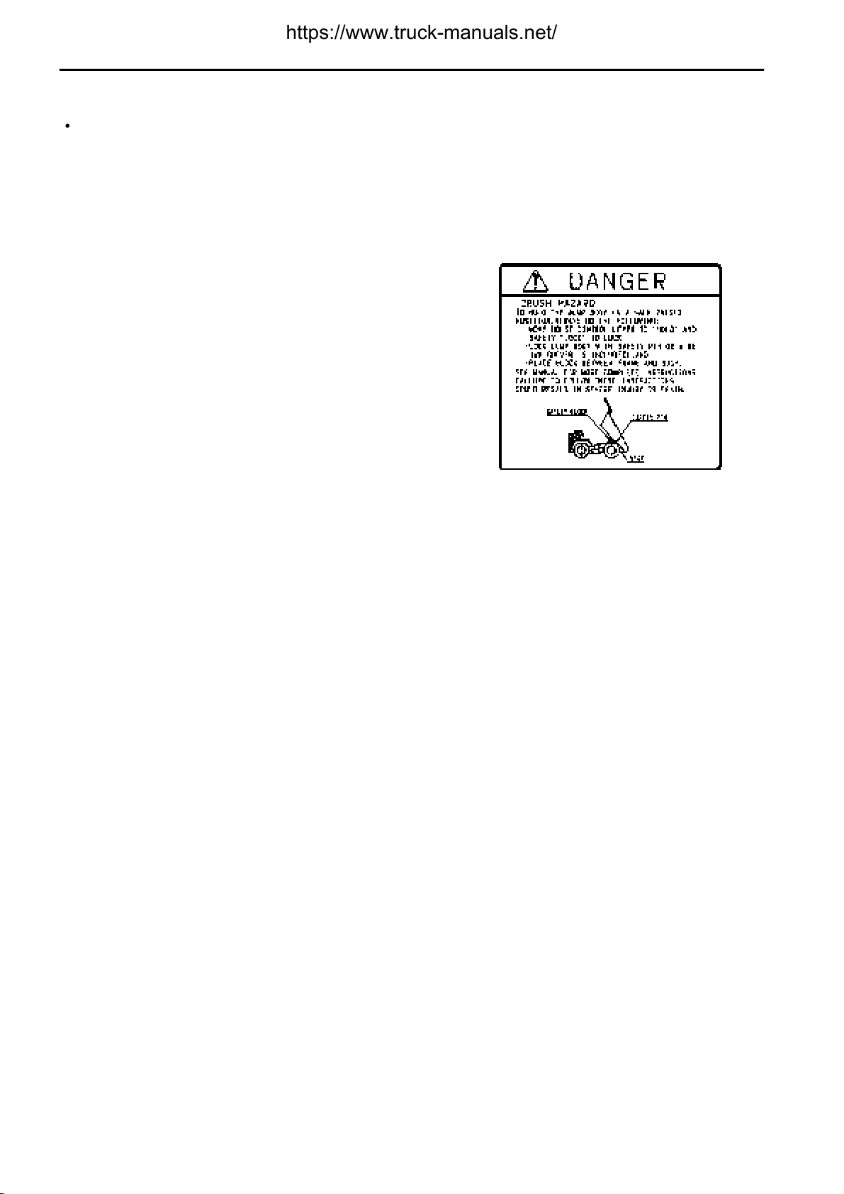
Example of safety label using words
FOREWORD
Safety labels using pictogram
Safety pictograms use a picture to express a level of hazardous
condition equivalent to the signal word. These safety pictograms
use pictures in order to let the operator or maintenance worker
understand the level and type of hazardous condition at all times.
Safety pictograms show the type of hazardous condition at the top
or left side, and the method of avoiding the hazardous condition at
the bottom or right side. In addition, the type of hazardous condition
is displayed inside a triangle and the method of avoiding the
hazardous condition is shown inside a circle.
Komatsu cannot predict every circumstance that might involve a potential hazard in operation and maintenance.
Therefore, the safety messages in this manual and on the machine may not include all possible safety precautions.
If any procedures or actions not specifically recommended or allowed in this manual are used, it is your responsibility
to take the necessary steps to ensure safety.
In no event should you engage in prohibited uses or actions described in this manual.
The explanations, values, and illustrations in this manual were prepared based on the latest information available
at that time. Continuing improvements in the design of this machine can lead to changes in detail which may not
be reflected in this manual. Consult Komatsu or your Komatsu distributor for the latest available information of your
machine or for questions regarding information in this manual.
The numbers in circles in the illustrations correspond to the numbers in ( ) in the text. (For example: 1 -> (1))
1 - 6
.
FOREWORD
INTENDED USE
INTENDED USE
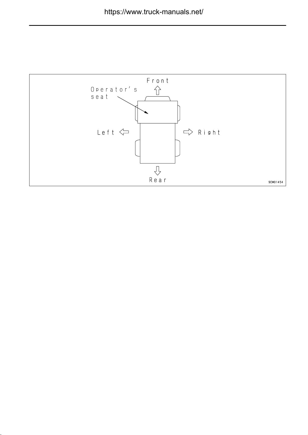
DIRECTIONS OF MACHINE
In this manual, the directions of the machine (front, rear, left, right) are determined according to the view from the
operator's seat in the direction of travel (front) of the machine.
1 - 7
.
LOCATION OF PLATES, TABLE TO ENTER SERIAL NO. AND DISTRIBUTOR
FOREWORD
LOCATION OF PLATES, TABLE TO ENTER SERIAL NO. AND
DISTRIBUTOR
When requesting service or ordering replacement parts, please inform your Komatsu distributor of the following
items.
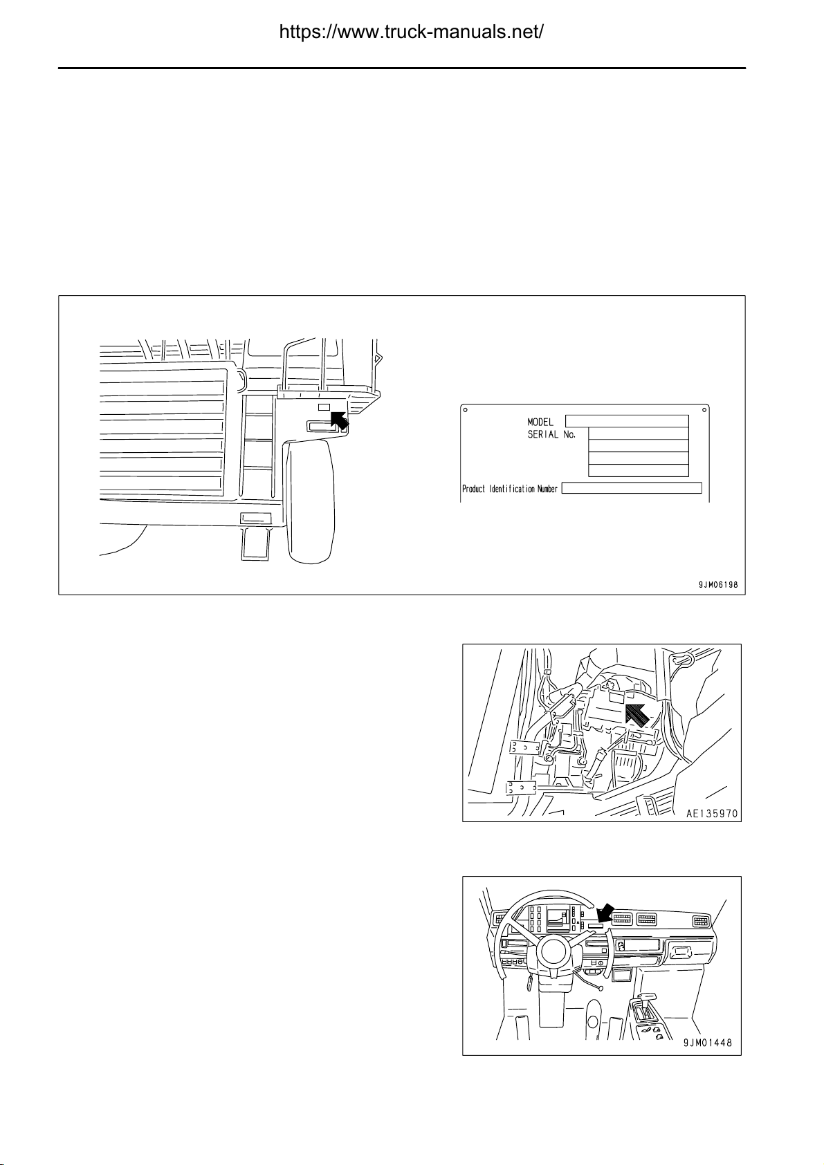
PRODUCT IDENTIFICATION NUMBER (PIN)/MACHINE SERIAL NO. PLATE
It is located on the left front end of the frame.
The design of the nameplate differs according to the territory.
ENGINE SERIAL NO. PLATE POSITION
The engine serial number plate is on the upperright side of (viewed
from the fan) the cylinder block (on the intake manifold cover).
SERVICE METER POSITION
It is located on the right side of the meter section.
1 - 8
.
FOREWORD
LOCATION OF PLATES, TABLE TO ENTER SERIAL NO. AND DISTRIBUTOR
TABLE TO ENTER SERIAL NO. AND DISTRIBUTOR
Machine serial No.
Engine serial No.
Product identification number (PIN)
Distributor name
Address
Service Personnel
Phone/Fax
1 - 9

.
CONTENTS
FOREWORD
CONTENTS
FOREWORD 1- 1
FOREWORD 1- 2
SAFETY INFORMATION 1- 5
INTENDED USE 1- 7
DIRECTIONS OF MACHINE 1- 7
LOCATION OF PLATES, TABLE TO ENTER SERIAL NO. AND DISTRIBUTOR 1- 8
PRODUCT IDENTIFICATION NUMBER (PIN)/MACHINE SERIAL NO. PLATE 1- 8
ENGINE SERIAL NO. PLATE POSITION 1- 8
SERVICE METER POSITION 1- 8
TABLE TO ENTER SERIAL NO. AND DISTRIBUTOR 1- 9
SAFETY 2- 1
SAFETY INFORMATION 2- 2
SAFETY LABELS 2- 4
POSITION FOR ATTACHING SAFETY LABELS 2- 5
SAFETY LABELS 2- 6
GENERAL PRECAUTIONS 2- 10
PRECAUTIONS DURING OPERATION 2- 18
BEFORE STARTING ENGINE 2- 18
AFTER STARTING ENGINE 2- 20
BATTERY 2- 23
TOWING 2- 25
PRECAUTIONS FOR MAINTENANCE 2- 26
PRECAUTIONS WITH TIRES 2- 32
OPERATION 3- 1
GENERAL VIEW 3- 2
GENERAL VIEW OF MACHINE 3- 2
GENERAL VIEW OF CONTROLS AND GAUGES 3- 3
EXPLANATION OF COMPONENTS 3- 5
MACHINE MONITOR 3- 5
SWITCHES 3- 22
CONTROL LEVERS AND PEDALS 3- 30
MECHATRONICS EQUIPMENT CONTROLLER 3- 34
SAFETY PIN 3- 35
DUST INDICATOR 3- 35
FUSES 3- 36
CAR STEREO 3- 38
AIR CONDITIONER 3- 47
CAR HEATER 3- 52
LOCATION OF FIRE EXTINGUISHER 3- 53
LOCATION OF FIRST AID KIT 3- 53
OPERATION 3- 54
CHECK BEFORE STARTING ENGINE 3- 54
STARTING ENGINE 3- 70
OPERATIONS, CHECKS AFTER STARTING ENGINE 3- 73
STOPPING ENGINE 3- 74
CHECKS AFTER STOPPING ENGINE 3- 74
MOVING MACHINE OFF (FORWARD, REVERSE), STOPPING 3- 75
SHIFTING GEAR 3- 80
TRAVELING DOWNHILL 3- 81
1 - 10

.
FOREWORD
STEERING THE MACHINE 3- 87
LOADING OPERATIONS 3- 87
DUMP OPERATIONS 3- 88
PRECAUTIONS FOR OPERATION 3- 89
PARKING MACHINE 3- 90
CHECKS AFTER COMPLETION OF WORK 3- 91
DRAIN WATER FROM AIR TANK 3- 91
LOCKING 3- 92
HANDLING TIRES 3- 93
DETERMINING AND MAINTAINING TRAVEL ROAD 3- 95
DETERMINING TRAVEL ROAD 3- 95
MAINTAINING TRAVEL ROAD 3- 95
TRANSPORTATION 3- 96
PRECAUTIONS WHEN TRANSPORTING 3- 96
STEPS FOR TRANSPORTATION 3- 96
METHOD OF SECURING MACHINE 3- 97
METHOD OF LIFTING MACHINE 3- 98
COLD WEATHER OPERATION 3-100
PRECAUTIONS FOR LOW TEMPERATURE 3-100
PRECAUTIONS AFTER COMPLETION OF WORK 3-101
AFTER COLD WEATHER 3-102
LONG-TERM STORAGE 3-103
BEFORE STORAGE 3-103
DURING STORAGE 3-103
AFTER STORAGE 3-103
PRECAUTIONS BEFORE TRAVELING AFTER LONG-TERM STORAGE 3-103
TROUBLESHOOTING 3-104
AFTER RUNNING OUT OF FUEL 3-104
METHOD OF TOWING MACHINE 3-104
IF BATTERY IS DISCHARGED 3-109
OTHER TROUBLE 3-113
MAINTENANCE 4- 1
GUIDES TO MAINTENANCE 4- 2
OUTLINE OF SERVICE 4- 4
HANDLING OIL, FUEL, COOLANT, AND PERFORMING OIL CLINIC 4- 4
OUTLINE OF ELECTRIC SYSTEM 4- 7
WEAR PARTS 4- 8
WEAR PARTS LIST 4- 8
RECOMMENDED FUEL, COOLANT, AND LUBRICANT 4- 9
USE OF FUEL, COOLANT AND LUBRICANTS ACCORDING TO AMBIENT TEMPERATURE 4- 10
RECOMMENDED BRANDS, RECOMMENDED QUALITY FOR PRODUCTS OTHER THAN
KOMATSU GENUINE OIL 4- 11
STANDARD TIGHTENING TORQUES FOR BOLTS AND NUTS 4- 12
TORQUE LIST 4- 12
PERIODIC REPLACEMENT OF SAFETY CRITICAL PARTS 4- 13
SAFETY CRITICAL PARTS 4- 14
MAINTENANCE SCHEDULE CHART 4- 15
MAINTENANCE SCHEDULE CHART 4- 15
SERVICE PROCEDURE 4- 18
INITIAL 250 HOURS SERVICE (ONLY AFTER THE FIRST 250 HOURS) 4- 18
CONTENTS
1 - 11

.
CONTENTS
WHEN REQUIRED 4- 19
CHECK BEFORE STARTING 4- 36
EVERY 100 HOURS SERVICE 4- 37
EVERY 250 HOURS SERVICE 4- 38
EVERY 500 HOURS SERVICE 4- 53
EVERY 1000 HOURS SERVICE 4- 58
EVERY 2000 HOURS SERVICE 4- 63
EVERY 4000 HOURS SERVICE 4- 69
EVERY 15000 HOURS SERVICE 4- 71
SPECIFICATIONS 5- 1
SPECIFICATIONS 5- 2
ATTACHMENTS, OPTIONS 6- 1
HANDLING PAYLOAD METER 6- 2
NAME OF PARTS 6- 2
EXTERNAL DISPLAY LAMPS 6- 3
OPERATING PAYLOAD METER 6- 5
TACHOGRAPH (TCO 15-6) 6- 13
EXPLANATION OF COMPONENTS 6- 13
METHOD OF USING KEY 6- 15
METHOD OF USE 6- 15
REVO TACHOGRAPH (TCO 15-7) 6- 17
EXPLANATION OF COMPONENTS 6- 17
METHOD OF USE 6- 19
USING DIFFERENTIAL LOCK 6- 21
DIFFERENTIAL LOCK PEDAL 6- 21
PRECAUTIONS AND METHOD OF USE 6- 22
OPERATION OF ABS AND ABS/ASR 6- 23
EXPLANATION OF COMPONENTS 6- 23
OPERATION METHOD 6- 25
PRECAUTIONS FOR USE 6- 26
TROUBLESHOOTING 6- 26
ARSC (AUTOMATIC RETARDER SPEED CONTROL) 6- 27
EXPLANATION OF COMPONENTS 6- 28
METHOD OF OPERATION 6- 30
TROUBLESHOOTING 6- 32
PMC (POWERTRAIN MANAGEMENT CONTROLLER) AND MOM (MESSAGE FOR
OPERATION AND MAINTENANCE) 6- 35
CHECK BEFORE STARTING 6- 35
ABNORMALITY DISPLAYED DURING OPERATION 6- 35
HOW TO DOWNLOAD THE STORED DATA IN PMC AND OTHER CONTROLLERS 6- 35
MESSAGE FOR OPERATION AND MAINTENANCE (MOM) 6- 36
ASR-II (AUTOMATIC SPIN REGULATOR II) 6- 41
EXPLANATION OF COMPONENTS 6- 41
ACTUATION OF ASR-II SYSTEM 6- 42
PRECAUTIONS WHEN USING 6- 42
TROUBLESHOOTING 6- 43
HANDLING AUTO-GREASING SYSTEM 6- 45
OUTLINE OF AUTO-GREASING SYSTEM 6- 45
SETTING GREASE CAN 6- 46
INITIAL SETTING OF AUTO-GREASING SYSTEM 6- 47
FOREWORD
1 - 12

.
FOREWORD
METHOD OF OPERATING AUTO-GREASING SYSTEM 6- 47
PRECAUTIONS WHEN HANDLING AUTO-GREASING SYSTEM 6- 48
POSITION OF EACH INJECTOR 6- 52
GREASING POINTS FOR EACH INJECTOR 6- 56
HIGH ALTITUDE SPECIFICATIONS 7- 1
EXPLANATION OF COMPONENTS 7- 2
SERVICE PROCEDURE 7- 3
CHECK BEFORE STARTING 7- 3
EVERY 2000 HOURS SERVICE 7- 4
INDEX 8- 1
CONTENTS
1 - 13
.
2 - 1

.
SAFETY INFORMATION
SAFETY
SAFETY INFORMATION
SAFETY LABELS 2- 4
POSITION FOR ATTACHING SAFETY LABELS 2- 5
SAFETY LABELS 2- 6
GENERAL PRECAUTIONS 2- 10
SAFETY RULES 2- 10
IF ABNORMALITIES ARE FOUND 2- 10
CLOTHING AND PERSONAL PROTECTIVE ITEMS 2- 10
FIRE EXTINGUISHER AND FIRST AID KIT 2- 10
SAFETY FEATURES 2- 10
KEEP MACHINE CLEAN 2- 11
INSIDE OPERATOR'S COMPARTMENT 2- 11
ALWAYS APPLY LOCK WHEN LEAVING OPERATOR'S SEAT 2- 11
HANDRAILS AND STEPS 2- 12
MOUNTING AND DISMOUNTIN 2- 12
PREVENTION OF BURNS 2- 13
FIRE PREVENTION 2- 13
ACTION IF FIRE OCCURS 2- 14
WINDOW WASHER LIQUID 2- 14
PRECAUTIONS WHEN USING ROPS (Roll Over Protective Structure) 2- 15
PRECAUTIONS FOR ATTACHMENTS 2- 15
UNAUTHORIZED MODIFICATION 2- 15
SAFETY AT WORKSITE 2- 15
WORKING ON LOOSE GROUND 2- 16
DO NOT GO CLOSE TO HIGH-VOLTAGE CABLES 2- 16
ENSURE GOOD VISIBILITY 2- 16
PRECAUTIONS ON INDOOR VENTILATION 2- 17
CHECKING SIGNALMAN'S SIGNALS AND SIGNS 2- 17
ASBESTOS DUST HAZARD PREVENTION 2- 17
2 - 2

.
SAFETY
PRECAUTIONS DURING OPERATION 2- 18
BEFORE STARTING ENGINE 2- 18
CHECKS BEFORE STARTING ENGINE, ADJUST 2- 18
PRECAUTIONS WHEN STARTING ENGINE 2- 18
PRECAUTIONS IN COLD AREAS 2- 19
AFTER STARTING ENGINE 2- 20
CHECK AFTER STARTING ENGINE 2- 20
PRECAUTIONS WHEN TRAVELING FORWARD OR REVERSE 2- 20
PRECAUTIONS DURING OPERATION 2- 21
PRECAUTIONS WHEN TRAVELING ON THE SLOPES 2- 21
PRECAUTIONS WHEN OPERATING DUMP BODY 2- 21
PRECAUTIONS FOR OPERATION 2- 21
METHOD OF USING BRAKES 2- 21
PRECAUTIONS UNDER THE SNOWING AND FREEZING CONDITION 2- 22
PRECAUTIONS FOR PARKING 2- 22
BATTERY 2- 23
BATTERY HAZARD PREVENTION 2- 23
STARTING WITH BOOSTER CABLES 2- 24
TOWING 2- 25
WHEN TOWING 2- 25
SAFETY INFORMATION
PRECAUTIONS FOR MAINTENANCE 2- 26
WARNING TAG 2- 26
KEEP WORK PLACE CLEAN AND TIDY 2- 26
APPOINT LEADER WHEN WORKING WITH OTHERS 2- 26
STOP ENGINE BEFORE CARRYING OUT INSPECTION AND MAINTENANCE 2- 27
TWO WORKERS FOR MAINTENANCE WHEN ENGINE IS RUNNING 2- 28
PROPER TOOLS 2- 28
HANDLING SUSPENTION CYLINDER 2- 29
PERSONNEL 2- 29
WORK UNDER THE MACHINE 2- 29
NOISE 2- 29
PRECAUTIONS WHEN USIN HAMMER 2- 29
REPAIR WELDING 2- 29
REMOVING BATTERY TERMINAL 2- 30
PRECAUTIONS WITH HIGH-PRESSURE OIL 2- 30
HANDLING HIGH-PRESSURE HOSES, PIPING 2- 30
WASTE MATERIALS 2- 30
MAINTENANCE OF AIR CONDITIONER 2- 30
COMPRESSED AIR 2- 31
PERIODIC REPLACEMENT OF SAFETY-CRITICAL PARTS 2- 31
PRECAUTIONS WITH TIRES 2- 32
HANDLING TIRES 2- 32
PRECAUTIONS WHEN STORING TIRE 2- 32
2 - 3

.
SAFETY LABELS
SAFETY
SAFETY LABELS
The following warning signs and safety labels are used on this machine.
Be sure that you fully understand the correct position and content of labels.
To ensure that the content of labels can be read properly, be sure that they are in the correct place and always
keep them clean. When cleaning them, do not use organic solvents or gasoline. These may cause the labels to
peel off.
There are also other labels in addition to the warning signs and safety labels. Handle those labels in the same
way.
If the labels are damaged, lost, or cannot be read properly, replace them with new ones. For details of the part
numbers for the labels, see this manual or the actual label, and place an order with Komatsu distributor.
2 - 4
.
SAFETY
SAFETY LABELS
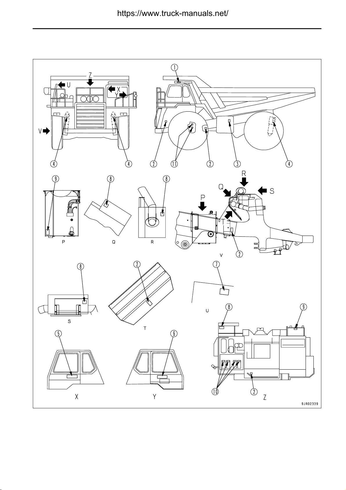
POSITION FOR ATTACHING SAFETY LABELS
2 - 5
.
SAFETY LABELS
SAFETY
SAFETY LABELS
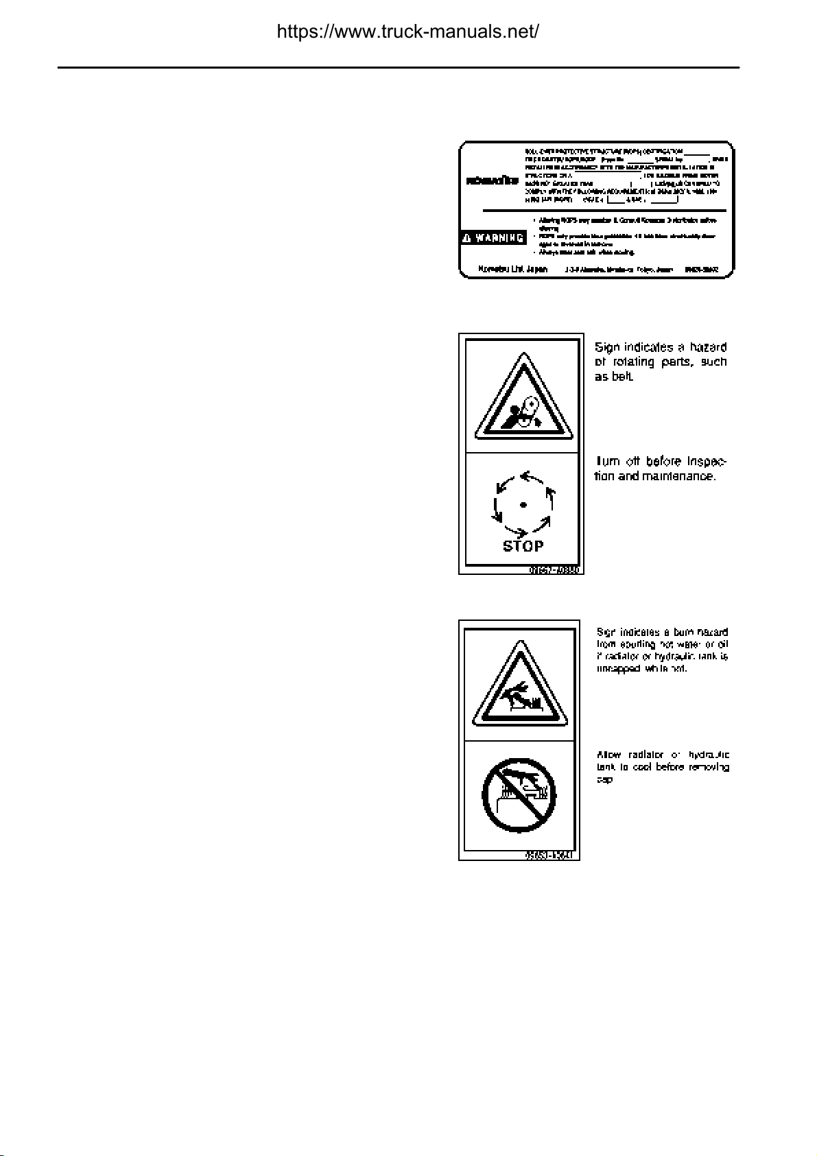
(1) Roll-over protective structure (ROPS) (09620-30202)
(2) Caution for checking engine room (09667-A0880)
(3) Caution for opening hydraulic tank cap
Caution for opening radiator cap (09653-A0641)
2 - 6
.
SAFETY
SAFETY
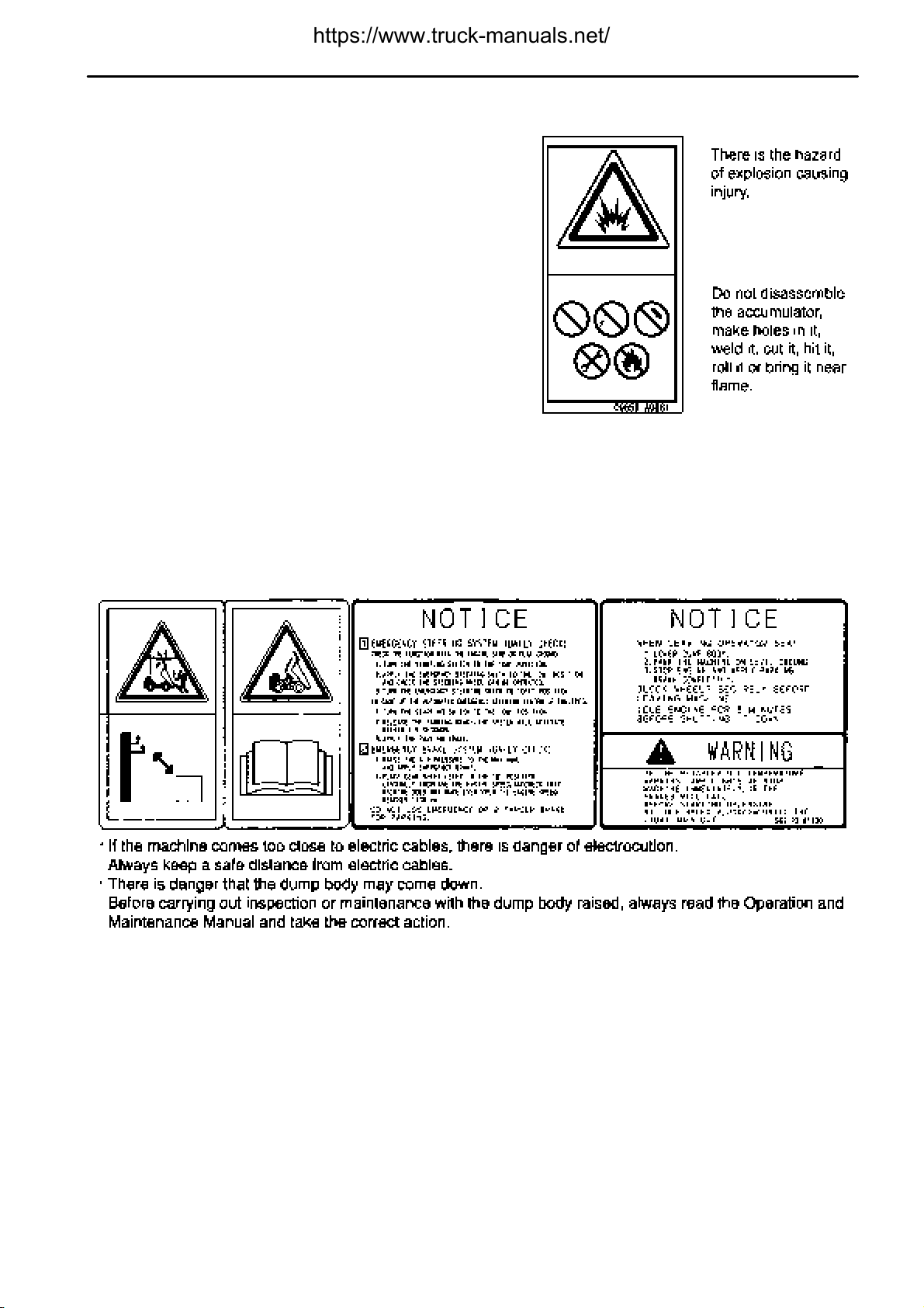
(4) Warning for handling suspension cylinder
(09659-A0881)
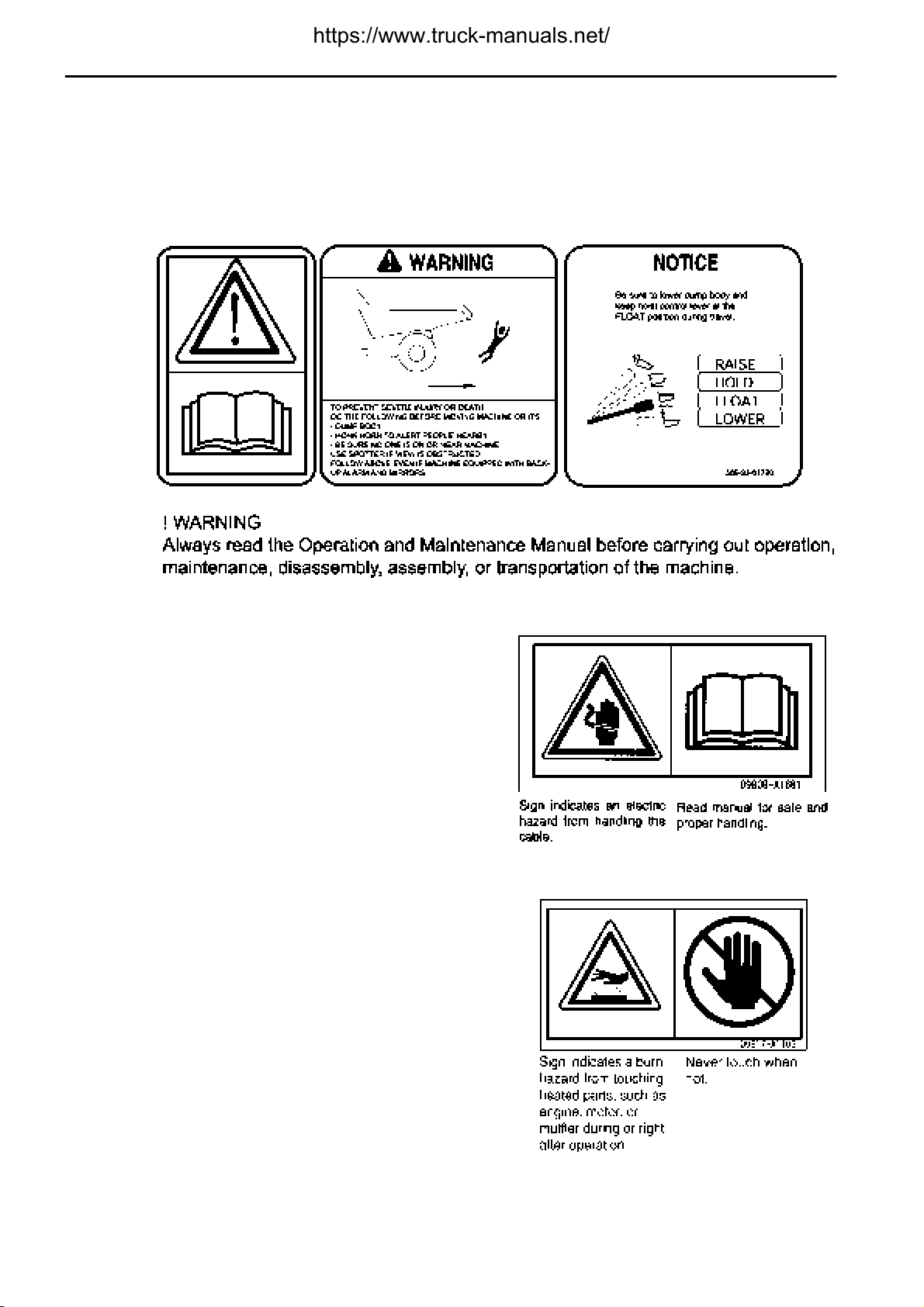
(5) Warnings for electric wire
Warnings for crush hazard when inspection and maintenance
Warnings for inspection of emergency steering system, emergency brake system
Warning for leaving operator's seat, stopping engine
Warning for retarder oil temperature
(569-93-61730)
SAFETY LABELS
SAFETY LABELS
2 - 7
.
SAFETY LABELS
(6) Cautions before starting
Cautions when traveling in reverse
Cautions for operating hoist control lever (dump lever)
(569-93-61720)
SAFETY
(7) Caution when handling battery cable (09808-A1681)
(8) Exhaust pipe is hot! (09817-A1103)
2 - 8
.
SAFETY
SAFETY
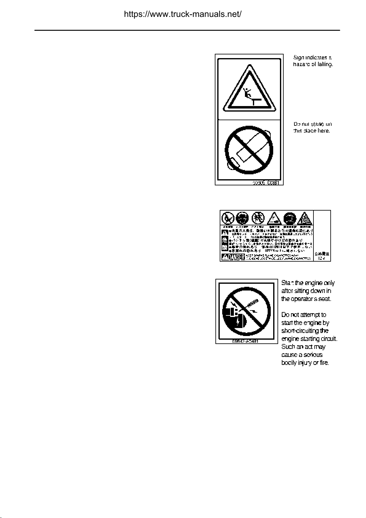
(9) Caution for avoiding falling down (09805-C0881)
SAFETY LABELS
SAFETY LABELS
(10) Caution when handling battery
(This plate is stick on the machine by the battery maker.)
(11) Jump start prohibited (09842-A0481)
(This plate is stick on the starting motor.)
2 - 9
.
GENERAL PRECAUTIONS
SAFETY
GENERAL PRECAUTIONS
SAFETY RULES
Only trained and authorized personnel can operate and maintain the machine.
Follow all safety rules, precautions and instructions when operating or performing maintenance on the machine.
If you are under the influence of alcohol or medication, your ability to safely operate or repair your machine may
be severly impaired putting yourself and everyone else on your jobsite in danger.
When working with another operator or with a person on worksite traffic duty, be sure that all personnel
understand all hand signals that are to be used.
IF PROBLEMS ARE FOUND
If you find any problems in the machine during operation or maintenance (noise, vibration, smell, incorrect gauges,
smoke, oil leakage, etc., or any abnormal display on the warning devices or monitor), report to the person in charge
and have the necessary action taken. Do not operate the machine until the problem has been corrected.
CLOTHING AND PERSONAL PROTECTIVE ITEMS
Do not wear loose clothing and accessories. There is a hazard that they may catch on control levers or other
protruding parts.
If you have long hair and it hangs out from your hard hat, there
is a hazard that it may get caught up in the machine, so tie your
hair up and be careful not to let it get caught.
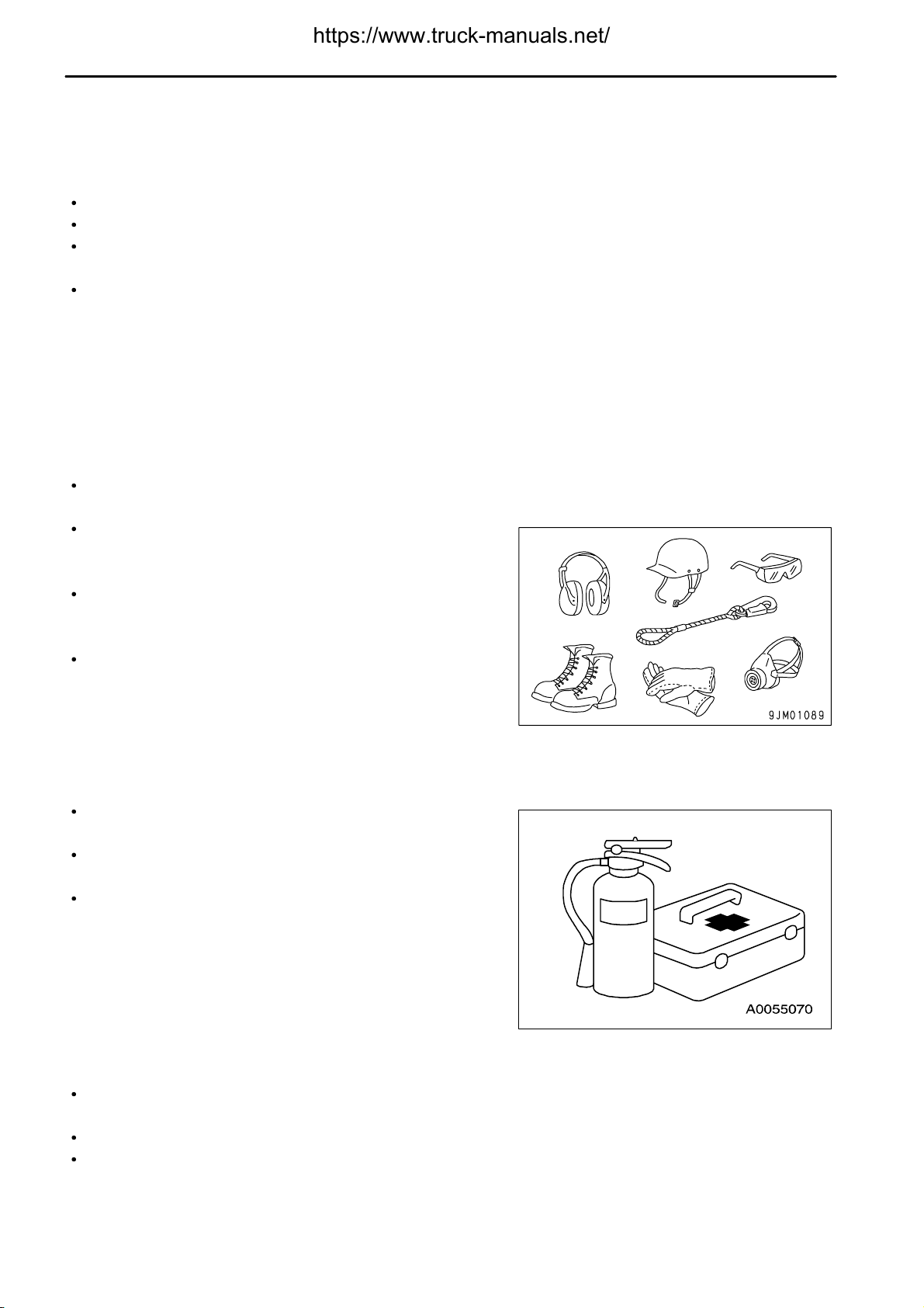
Always wear a hard hat and safety shoes. If the nature of the
work requires it, wear safety glasses, mask, gloves, ear plugs,
and safety belt when operating or maintaining the machine.
Check that all protective equipment functions properly before
using it.
FIRE EXTINGUISHER AND FIRST AID KIT
Always follow the precautions below to prepare for action if any injury or fire should occur.
Be sure that fire extinguishers have been provided and read the
labels to ensure that you know how to use them in emergencies.
Carry out periodic inspection and maintenance to ensure that
the fire extinguisher can always be used.
Provide a first aid kit in the storage point. Carry out periodic
checks and add to the contents if necessary.
SAFETY FEATURES
Be sure that all guards and covers are in their proper position. Have guards and covers repaired immediately if
they are damaged.
Understand the method of use of safety features and use them properly.
Never remove any safety features. Always keep them in good operating condition.
2 - 10
.
SAFETY
KEEP MACHINE CLEAN
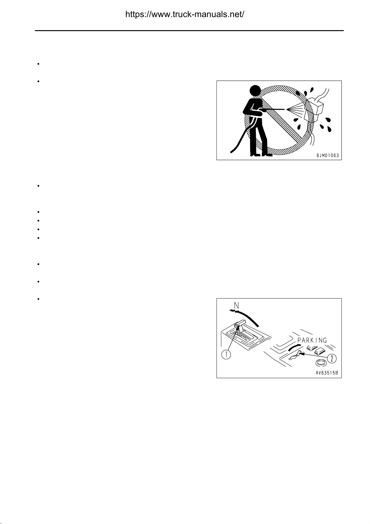
If water gets into the electrical system, there is a hazard that it will cause malfunctions or misoperation. Do not
use water or steam to wash the electrical system (sensors, connectors).
If inspection and maintenance is carried out when the machine
is still dirty with mud or oil, there is a hazard that you will slip and
fall, or that dirt or mud will get into your eyes. Always keep the
machine clean.
INSIDE OPERATOR'S COMPARTMENT
When entering the operator's compartment, always remove all mud and oil from the soles of your shoes.
If you operate the pedal with mud or oil affixed to your shoes, your foot may slip and this may cause a serious
accident.
Do not leave parts or tools lying around the operator's compartment.
Do not stick suction pads to the window glass. Suction pads act as a lens and may cause fire.
Do not use cellular telephones inside the operator's compartment when driving or operating the machine.
Never bring any dangerous objects such as flammable or explosive items into the operator's compartment.
GENERAL PRECAUTIONS
ALWAYS APPLY LOCK WHEN LEAVING OPERATOR'S SEAT
Before adjusting or standing up from the operator's seat, always set the gear shift lever to the N position and the
parking brake valve lever to the PARKING position, then stop the engine.
If you touch or bump the control levers unintentionally, the machine could suddenly move, and cause an accident
that might result in bodily harm.
Place gear shift lever (1) at neutral and set parking brake valve
lever (2) to the PARKING position.
Lower the dump body, set the dump lever to the HOLD position,
then apply the lock.
Stop the engine. Apply all the lock and always remember to take
the key with you and keep where it should be.
2 - 11
.
GENERAL PRECAUTIONS
HANDRAILS AND STEPS
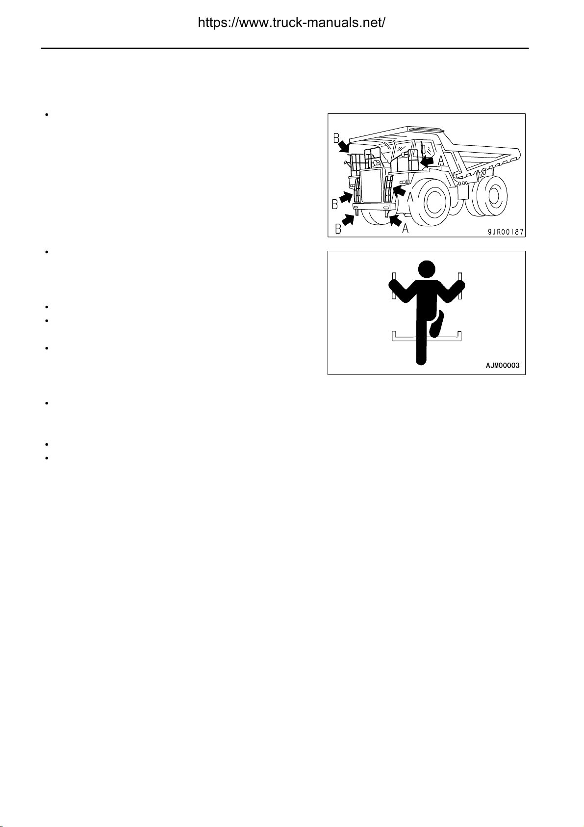
To prevent personal injury caused by slipping or falling off the machine, always do as follows.
Use the handrails and steps marked by arrows in the diagram
below when getting on or off the machine.
A: For use whengetting on or off the operator's seat fromthe left
door
B: For use when getting on or off the operator's seat from the
engine hood or right door
To ensure safety, always face the machine and maintain
three-point contact (both feet and one hand, or both hands and
one foot) with the handrails and steps to ensure that you support
yourself.
Do not grip the dump lever when getting on or off the machine.
Never climb on the engine hood or covers where there are no
non-slip pads.
Before getting on or off the machine, check the handrails and
steps, and if there is any oil, grease, or mud on them, wipe it off
immediately. In addition, repair any damage and tighten any
loose bolts.
Do not get on or off the machine while holding tools in your hand.
SAFETY
MOUNTING AND DISMOUNTING
Never jump on or off the machine. Never get on or off a moving machine.
If the machine starts to move when there is no operator on the machine, do not jump on to the machine and try
to stop it.
2 - 12
.
SAFETY
PREVENTION OF BURNS
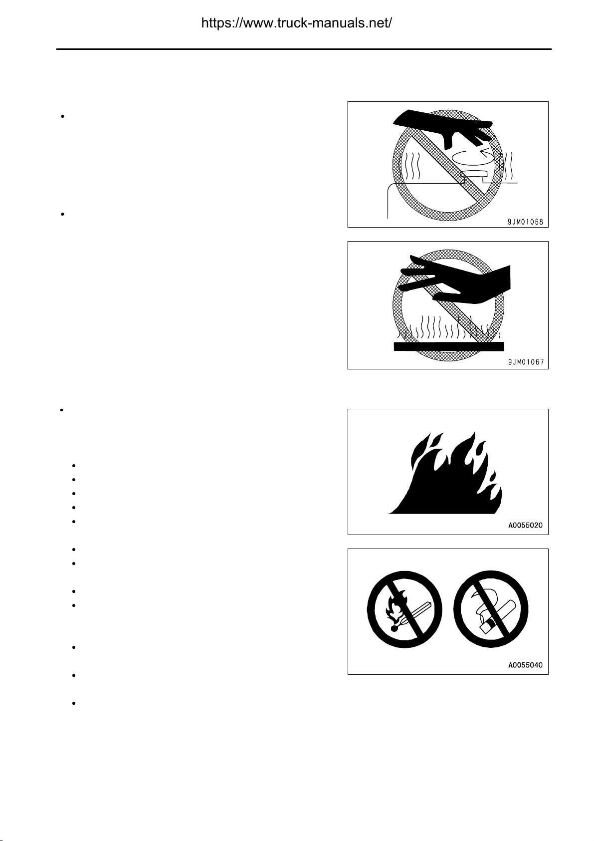
Hot coolant
To prevent burns from hot water or steam spurting out when
checking or draining the coolant, wait for the water to cool to a
temperature where it is possible to touch the radiator cap by
hand before starting the operation. Even when the coolant has
cooled down, loosen the cap slowly to relieve the pressure
inside the radiator before removing the cap.
Hot oil
To prevent burns from hot oil spurting out when checking or
draining the oil, wait for the oil to cool to a temperature where it
is possible to touch the cap or plug by hand before starting the
operation. Even when the oil has cooled down, loosen the cap
or plug slowly to relieve the internal pressure before removing
the cap or plug.
GENERAL PRECAUTIONS
FIRE PREVENTION
Fire caused by fuel or oil
Fuel, oil, antifreeze, and window washer liquid are particularly
flammable and can be hazardous. To prevent fire, always
observe the following:
Do not smoke or use any flame near fuel or oil.
Stop the engine before refueling.
Do not leave the machine while adding fuel or oil.
Tighten all fuel and oil caps securely.
Do not spill fuel on overheated surfaces or on parts of the
electrical system.
Use well-ventilated areas for adding or storing oil and fuel.
Keep oil and fuel in the determined place and do not allow
unauthorized persons to enter.
After adding fuel or oil, wipe up any spilled fuel or oil.
When carrying out grinding or welding work on the chassis,
move any flammable materials to a safe place before
starting.
When washing parts with oil, use a non-flammableoil. Diesel
oil and gasoline may catch fire, so do not use them.
Put greasy rags and other flammable materials into a safe
container to maintain safety at the work place.
Do not weld or use a cutting torch to cut any pipes or tubes
that contain flammable liquids.
2 - 13

.
GENERAL PRECAUTIONS
Fire caused by accumulation of flammable material.
Remove any dry leaves, chips, pieces of paper, dust, or any other flammable materials accumulated or affixed
around the engine, exhaust manifold, muffler, or battery, or inside the undercovers.
Fire coming from electric wiring
Short circuits in the electrical system can cause fire.
Always keep electric wiring connections clean and securely tightened.
Check the wiring every day for looseness or damage. Tighten any loose connectors or wiring clamps. Repair
or replace any damaged wiring.
Fire coming from hydraulic line
Check that all the hose and tube clamps, guards, and cushions are securely fixed in position.
If they are loose, they may vibrate during operation and rub against other parts. This may lead to damage to the
hoses, and cause high-pressure oil to spurt out, leading to fire damage or serious injury.
SAFETY
Explosion caused by lighting equipment
When checking fuel, oil, battery electrolyte, window washer fluid, or coolant, always use lighting with
anti-explosion specifications. If such lighting equipment is not used, there is danger of explosion that may
cause serious injury.
When taking the electrical power for the lighting from the machine itself, follow the instructions in this manual.
ACTION IF FIRE OCCURS
If a fire occurs, escape from the machine as follows.
Turn the start switch OFF to stop the engine.
Use the handrails and steps to get off the machine.
WINDOW WASHER LIQUID
Use an ethyl alcohol base washer liquid.
Methyl alcohol base washer liquid may irritate your eyes, so do not use it.
2 - 14
.
SAFETY
PRECAUTIONS WHEN USING ROPS (Roll Over Protective Structure)
Install ROPS when working in places where there is danger of
falling rocks, such as in mines and quarries, or in places where
there is danger of rolling over.
If ROPS is installed, do not remove it when operating the
machine.
ROPS is installed to protect the operator when machine rolls
over. When machine rolls over, ROPS supports its weight and
absorbs its impact energy.
If ROPS is modified, its strength may be reduced. When
modifying, consult your Komatsu distributor.
If ROPS is deformed by falling objects or by rolling over, its
strength lowers and its design functions cannot be maintained.
In this case, besure to ask your Komatsu distributor about repair
method.
Even when the ROPS isinstalled, if you do notfasten yourseat belt
securely, it cannot protect you properly. Always fasten your seat
belt when operating the machine.
GENERAL PRECAUTIONS
PRECAUTIONS FOR ATTACHMENTS, OPTIONS
When installing optional parts or attachments, there may be problems with safety or legal restrictions. Therefore
contact your Komatsu distributor for advice.
Any injuries, accidents, or product failures resulting from the use of unauthorized attachments or parts will not be
the responsibility of Komatsu.
When installing and using optional attachments, read the instruction manual for the attachment, and the general
information related to attachments in this manual.
UNAUTHORIZED MODIFICATION
Any modification made without authorization from Komatsu can create hazards. Before making a modification,
consult your Komatsu distributor.
Komatsu will not be responsible for any injuries, accidents, product failures or other property damages resulting
from modifications made without authorization from Komatsu.
SAFETY AT WORKSITE
Before starting operations, thoroughly check the area for any unusual conditions that could be dangerous.
Check the terrain and condition of the ground at the worksite, and determine the safest method of operation. Do
not operate where there is a hazard of landslides or falling rocks.
Take necessary measures to prevent any unauthorized person from entering the operating area.
When traveling or operating in shallow water or on soft ground, check the shape and condition of the bedrock, and
the depth and speed of flow of the water before starting operations.
Always design and maintain the roads on the jobsite so that the machines can travel safely.
2 - 15

.
GENERAL PRECAUTIONS
WORKING ON LOOSE GROUND
Avoid traveling or operating your machine too close to the edge of cliffs, overhangs, and deep ditches. The
ground may be weak in such areas. If the ground should collapse under the weight or vibration of the machine,
there is a hazard that the machine may fall or tip over. Remember that the soil after heavy rain or blasting or after
earthquakes is weak in these areas.
When working on embankments or near excavated ditches, there is a hazard that the weight and vibration of the
machine will cause the soil to collapse. Before starting operations, take steps to ensure that the ground is safe
and to prevent the machine from rolling over or falling.
DO NOT GO CLOSE TO HIGH-VOLTAGE CABLES
Do not travel or operate the machine near electric cables. There is a hazard of electric shock, which may cause
serious injury or property damage. On jobsites where the machine may go close to electric cables, always do as
follows.
Before starting work near electric cables, inform the local power company of the work to be performed, and ask
them to take the necessary action.
Even going close to high-voltage cables can cause electric
shock, which may cause serious burns or even death. Always
maintain a safe distance (see the table on the right) between the
machine and the electric cable. Check with the local power
company about safe operating procedure before starting
operations.
To prepare for any possible emergencies, wear rubber shoes
and gloves. Lay a rubber sheet on top of the seat, and be careful
not to touch the chassis with any exposed part of your body.
Use a signalman to give warning if the machine approaches too
close to the electric cables.
When carrying out operations near high voltage cables, do not
let anyone near the machine.
If the machine should come too close or touch the electric cable, to prevent electric shock, the operator should
not leave the operator's compartment until it has been confirmed that the electricity has been shut off.
Also, do not let anyone near the machine.
Voltage of Cables Safety Distance
100 V - 200 V Over 2 m (7 ft)
6,600 V Over 2 m (7 ft)
22,000 V Over 3 m (10 ft)
66,000 V Over 4 m (14 ft)
154,000 V Over 5 m (17 ft)
187,000 V Over 6 m (20 ft)
275,000 V Over 7 m (23 ft)
500,000 V Over 11 m (36 ft)
SAFETY
ENSURE GOOD VISIBILITY
Check for any persons or obstacles in the area around the machine and check the conditions of the jobsite to
ensure that operations and travel can be carried out safely. Always do as follows.
When working in dark places, turn on the working lamp and front lamps installed to the machine, and set up
additional lighting in the work area if necessary.
Stop operations if the visibility is poor, such as in mist, snow, rain, or dust.
2 - 16

.
SAFETY
PRECAUTIONS ON INDOOR VENTILATION
Exhaust fumes from the engine can kill.
If it is necessary to start the engine within an enclosed area, or
when handling fuel, flushing oil, or paint, open the doors and
windows to ensure that adequate ventilation is provided to
prevent gas poisoning.
CHECKING SIGNALMAN'S SIGNALS AND SIGNS
Set up signs to inform of road shoulders and soft ground. If the visibility is not good, position a signalman if
necessary. Operators should pay careful attention to the signs and follow the instructions from the signalman.
Only one signalman should give signals.
Make sure that all workers understand the meaning of all signals and signs before starting work.
GENERAL PRECAUTIONS
ASBESTOS DUST HAZARD PREVENTION
Asbestos dust in theair can cause lung cancer if it is inhaled. There
is danger of inhaling asbestos when working on jobsites handling
demolition work or work handling industrial waste. Always observe
the following.
Spray water to keep down the dust when cleaning. Do not use
compressed air for cleaning.
If there is danger that there may be asbestos dust in the air,
always operate the machine from an upwind position. All
workers should use an approved respirator.
Do not allow other persons to approach during the operation.
Always observe the rules and regulations for the work site and
environmental standards.
This machine does not use asbestos, but there is a danger that imitation parts may contain asbestos, so always use
genuine Komatsu parts.
2 - 17

.
PRECAUTIONS DURING OPERATION
SAFETY
PRECAUTIONS DURING OPERATION
BEFORE STARTING ENGINE
If there is a warning tag hanging from gear shift lever (1), do not
start the engine or touch the levers.
CHECKS BEFORE STARTING ENGINE, ADJUST
Carry out the following checks before starting the engine at the beginning of the day's work.
Remove all dirt from the surface of the window glass to ensure a good view.
Remove all dirt from the surface of the lens of the front lamps, working lamps, and rear combination lamp, and
check that they light up correctly.
Check the coolant level, fuel level, and oil level in engine oil pan, check for clogging of the air cleaner, and check
for damage to the electric wiring.
Check that there is no mud ordust accumulatedaround the movable parts of the accelerator pedal or brake pedal,
and check that the pedals work properly.
Adjust the operator'sseat to a position where it is easy to carry out operations, and check that there is no damage
or wear to the seat belt or mounting clamps.
Check the operation of the instruments and gauges, check the angle of the mirror, and check that the control
levers are all at the Neutral position.
Before starting the engine, make sure that the safety lock lever is in the LOCK position.
Adjust the mirrors so that the rear of the machine can be seen clearly from the operator's seat.
Refer to "WALK-AROUND CHECK (PAGE 3-54)".
Check that there are no persons or obstacles above, below, or in the area around the machine.
PRECAUTIONS WHEN STARTING ENGINE
Start and operate the machine only while seated.
Do not attempt to start the engine by short-circuiting the engine starting circuit. Such an act may cause a serious
bodily injury or fire.
When starting the engine, sound the horn as a warning.
If another person is allowed on the machine, that person may sit only in the assistant's seat.
2 - 18

.
SAFETY
PRECAUTIONS IN COLD AREAS
Carry out the warming-up operation thoroughly. If the machine is not thoroughly warmed up before the control
levers are operated, the reaction of the machine will be slow, and this may lead to unexpected accidents.
If the battery electrolyte is frozen, do not charge the battery or start the engine with a different power source.
There is a hazard that this will ignite the battery and cause the battery to explode.
Before charging or starting the engine with a different power source, melt the battery electrolyte and check that
there is no leakage of electrolyte before starting.
Drain water in the air tank.
If there is no sound of the air being released when the service brake or parking brake are operated, check the air
tank pressure and remove any snow or ice from around the brake valve.
PRECAUTIONS DURING OPERATION
2 - 19

.
PRECAUTIONS DURING OPERATION
SAFETY
AFTER STARTING ENGINE
CHECKS AFTER STARTING ENGINE
When carrying out the checks, move the machine to a wide area where there are no obstructions, and operate
slowly. Do not allow anyone near the machine.
Always fasten your seat belt.
Check the operation of travel, steering and brake systems, and dump body control system.
Check for any problem in the sound of the machine, vibration, heat, smell, or gauges; check also that there is no
leakage of oil or fuel.
If any problem is found, carry out repairs immediately.
PRECAUTIONS WHEN TRAVELING FORWARD OR REVERSE
Before travelling, check again that there is no one in the
surrounding area, and that there are no obstacles.
Before travelling, sound the horn to warn people in the area.
Always operate the machine only when seated.
Always fasten your seat belt.
If another person is allowed on the machine, that person may sit
only in the assistant's seat.
Check that the backup alarm (backup warning buzzer) works
properly.
Always close the door and the window of the operator's
compartment and check that the door lock is applied.
Always be sure to carry out the above precautions even when the
machine is equipped with mirrors.
2 - 20

.
SAFETY
PRECAUTIONS DURING OPERATION
Never turn the key in the starting switch to the OFF position. It is dangerous if the engine stops when the machine
is traveling, because the steering becomes heavy. If the engine stops, depress the brake pedal immediately to
stop the machine.
Lower the dump body, setting the dump lever at FLOAT position, then travel.
To prevent the machine from rolling over when traveling on rough ground, travel at low speed and avoid sudden
changes in direction.
When traveling or carrying out operations, always keep a safe distance from people, structures, or other
machines to avoid coming into contact with them.
When passing over bridges or structures, check first that the structure is strong enough to support the weight of
the machine.
When operating in tunnels, inside buildings, or under bridges or electric wires, or other places where the height
is limited, operate slowly and be extremely careful not to let the machine or dump body contact anything.
Continuous long time traveling at high speed may cause tires to heat up, abnormally increasing the inflation
pressure inside the tires, and to blow up. The explosion of the tire is very destructive, and it can lead to serious
injury or death.
Contact with your Komatsu distributor before doing long continuous traveling.
PRECAUTIONS DURING OPERATION
PRECAUTIONS WHEN TRAVELING ON THE SLOPES
To prevent the machine from tipping over or slipping to the side, always do as follows.
When traveling downhill, use the retarder brake to reduce speed. Do not turn the steering wheel suddenly.
Travel on grass, fallen leaves, or wet steel plates with low speed. Even with slight slopes there is a hazard that
the machine may slip.
If the engine should stop on a slope, apply the brakes fully and apply the parking brake also to stop the machine.
Do not shift the gear while traveling downhill or travel downhill with the transmission in neutral. If this is neglected,
the engine does not work as a brake, and that is dangerous. Be sure to set the transmission in one of the lower
gear speeds. In addition, apply the brake and use the engine as a brake, if necessary.
PRECAUTIONS WHEN OPERATING DUMP BODY
Before starting the dumping operation, check to be sure there is no person or object behind the machine.
Stop the machine in the correct position, and check again that there is no person or object behind the machine.
Give the determined signal, then slowly operate the dump body.
If necessary, use blocks for the wheels or position a flagman.
Do not carry out dumping operations on slopes. The machine stability will become poor and there is the danger
that it could tip over.
Do not travel with the body raised.
Do not leave or return to the operator's seat during loading work.
PRECAUTIONS FOR OPERATION
Do not load the dump body above the maximum payload. The brakes will lose their effect.
When operating in tunnels, or under bridges or electric wires, or in other places where the height is limited,
operate slowly and be extremely careful not to let the dump body contact anything.
To prevent accidents caused by hitting other objects, always operate the machine at a speed which is safe for
operation, particular in confined spaces, indoors, and in places where there are other machines.
METHOD OF USING BRAKES
Do not rest your foot on the brake pedal unless it is necessary.
Do not depress the brake pedal repeatedly if not necessary.
When traveling downhill, use the braking force of the engine, and always use the retardar at the same time.
2 - 21

.
PRECAUTIONS DURING OPERATION
RECAUTIONS UNDER THE SNOWING AND FREEZING CONDITION
Snow-covered or frozen surfaces are slippery, so be extremely careful when traveling or operating the machine,
and do not operate the levers suddenly. Even a slight slope may cause the machine to slip, so be particularly
careful when working on slopes.
With frozen ground surfaces, the ground becomes soft when the temperature rises, and this may cause the
machine to tip over.
If the machine enters deep snow, there is a hazard that it may tip over or become buried in the snow. Be careful
not to leave the road shoulder or to get trapped in a snow drift.
When traveling on snow-covered roads, always fit tire chains.
When traveling on snow-covered slopes, never apply the foot brake suddenly. Reduce the speed and use the
engine as a brake while applying the foot brake intermittently (depress the brake intermittently several times). If
necessary, lower the bucket to the ground to stop the machine.
When the loaded materials in the dump body are frozen, do not dump. There is a danger that the machine could
tip over.
SAFETY
PRECAUTIONS FOR PARKING
Park the machine on firm, level ground.
Select a place where there is no hazard of falling rocks or
landslides, or of flooding if the land is low.
When leaving the machine, place the gear shift lever (1) at
neutral and set the parking valve lever (2) to the PARKING
position. Then, stop the engine.
Always close the operator's cab door, and use the key to lock all
the equipment in order to prevent any unauthorized person from
moving the machine. Always remove the key, take it with you,
and leave it in the specified place.
If it is necessary to park the machine on a slope, set blocks
under the wheels to prevent the machine from moving.
2 - 22

.
SAFETY
PRECAUTIONS DURING OPERATION
BATTERY
BATTERY HAZARD PREVENTION
Battery electrolyte contains sulphuric acid, and batteries generate flammable hydrogen gas, which may explode.
Mistaken handling can lead to serious injury or fire. For this reason, always observe the following precautions.
Do not use or charge the battery if the battery electrolyte level is below the LOWER LEVEL line. This may cause
an explosion. Check the battery electrolyte level periodically and add distilled water to bring the electrolyte level
to the UPPER LEVEL line.
When working with batteries, always wear safety glasses and rubber gloves.
Never smoke or use any flame near the battery.
If you spill acid on your clothes or skin, immediately flush the
area with large amount of water.
If acid gets into your eyes, flush them immediately with large
amount of water and seek medical attention.
Before working with batteries, turn the starting switch to the OFF position.
As there is a hazard that sparks will be generated, always do as follows.
Do not let tools or other metal objects make any contact between the battery terminals. Do not leave tools or other
metal objects lying around near the battery.
Always disconnect the negative (-) terminal (ground side) first when removing the battery; when installing the
battery, connect the positive(+) terminalfirst, and connect the ground last. Tighten the battery terminals securely.
Flammable hydrogen gas is generated when the battery is charged, so remove the battery from the chassis, take
it to a well-ventilated place, and remove the battery caps before charging it.
Tighten the battery caps securely.
Install the battery securely to the determined place.
2 - 23

.
PRECAUTIONS DURING OPERATION
STARTING WITH BOOSTER CABLES
If any mistake is made in the method of connecting the booster
cables, it may cause the battery to explode, so always do as
follows.
When starting with a booster cable, carry out the starting
operation with two workers (one worker sitting in the operator's
seat and the other working with the battery).
When starting from another machine, do not allow the two
machines to touch.
When connecting the booster cables, turn the starting switch
OFF position for both the normal machine and problem
machine. There is a hazard that the machine will movewhen the
power is connected.
Be sure to connect the positive (+) cable first when installing the
booster cables. Disconnect the negative (-) cable (ground side)
first when removing them.
When removing the booster cables, be careful not to let the
booster cable clips touch each other or to let the clips touch the
machine.
Always wear safety glasses and rubbergloves whenstarting the
engine with booster cables.
When connecting a normal machine to a problem machine with
booster cables, always use a normal machine with the same
battery voltage as the problem machine.
For details of the starting procedure when using booster cables,
see "STARTING ENGINE WITH BOOSTER CABLE (PAGE
3-111)" in the OPERATION section.
SAFETY
2 - 24

.
SAFETY
PRECAUTIONS DURING OPERATION
TOWING
WHEN TOWING
When towing or being towed, mistakes in the method of selecting and inspecting the wire rope or drawbar, or in the
method of towing may lead to serious personal injury.
For details of the procedure for towing, see the "METHOD OF TOWING MACHINE (PAGE 3-104)"
Always confirm that the wire rope or drawbar used for towing
has ample strength for the weight of the machine being towed.
Never use a wire rope which has cut strands (A), reduced
diameter (B), or kinks (C). There is danger that the rope may
break during the towing operation.
Always wear leather gloves when handling wire rope.
Never tow a machine on a slope.
During the towing operation, never stand between the towing
machine and the machine being towed.
2 - 25

.
PRECAUTIONS FOR MAINTENANCE
SAFETY
PRECAUTIONS FOR MAINTENANCE
WARNING TAG
Attach the DO NOT OPERATE warning tag to gear shift lever (1)
in the operator's cab during the inspection and maintenance.
Attach additional warning tags around the machine if necessary.
Warning tag Part No. 09963-03001
Keep the warning tag in the tool box when it is not used. If the
tool box is unavailable, keep it in the case for operation manual.
If any person other than the serviceman starts the engine, or
touches or operates the gear shift lever or dump lever while the
serviceman is carrying out service or maintenance of the
machine, it may lead to serious injury.
KEEP WORK PLACE CLEAN AND TIDY
Do not leave hammers or other tools lying around in the work place. Wipe up all grease, oil, or other substances
that will cause you to slip. Always keep the work place clean and tidy to enable you to carry out operations safely.
If the work place is not kept claen and tidy, there is the danger that you will trip, slip, or fall over and injure yourself.
APPOINT LEADER WHEN WORKING WITH OTHERS
When repairing the machine or when removing and installing the attachment, appoint a leader and follow his
instructions during the operation.
When working with others, misunderstandings between workers can lead to serious accidents.
2 - 26

.
SAFETY
STOP ENGINE BEFORE CARRYING OUT INSPECTION AND MAINTENANCE
Stop the machine on firm, level ground.
Select a place where there is no hazard of falling rocks or
landslides, or of flooding if the land is low.
Lower the dump body and stop the engine.
Set parking brake valve lever to the PARKING position and put
blocks (1) under the tires to prevent the machine from moving.
PRECAUTIONS FOR MAINTENANCE
2 - 27

.
PRECAUTIONS FOR MAINTENANCE
TWO WORKERS FOR MAINTENANCE WHEN ENGINE IS RUNNING
To prevent injury, do not carry out maintenance with the engine
running. If maintenance must be carried out with the engine
running, carry out the operation with at least two workers and do as
follows.
One worker must always sit in the operator's seat and be ready
to stop the engine at any time. All workers must maintain
contact with the other workers.
Lock the dump lever in HOLD position to prevent the operation
cab from moving. Also, set parking brake valve lever to the
PARKING position to prevent the machine from moving.
SAFETY
When carrying out operations near the fan, fan belt, or other rotating parts, there is a hazard of being caught in
the parts, so be careful not to come close.
Do not touch any control levers. If any control lever must be operated, give a signal to the other workers to warn
them to move to a safe place.
Never drop or insert tools or other objects into the fan or fan belt. Parts may break or be sent flying.
PROPER TOOLS
Use only tools suited to the task and be sure to use the tools
correctly. Using damaged, low quality, faulty, makeshift tools or
improper use of the tools could cause serious personal injury.
2 - 28

.
SAFETY
HANDLING SUSPENSION CYLINDER
The suspension cylinder is charged with high-pressure nitrogen gas. If any mistake is made in handling, it may lead
to serious injury. To prevent this, always do as follows.
Do not remove or disassemble the cylinder.
Do not bring it near flame or dispose of it in fire.
Do not make holes in it, weld it, or use a cutting torch.
Do not bear any shock by hammering, rolling or similar activity.
Ask for your Komatsu distributor when sealing gas into the cylinder or releasing gas from it.
PERSONNEL
Only authorized personnel can service and repair the machine. Do not allow unauthorized personnel into the area.
If necessary, employ an observer.
WORK UNDER THE MACHINE
If it is necessary to go under the machine when it is raised in
order to carry out service or maintenance, support the machine
securely with blocks and stands strong enough to support the
weight of the machine.
When carrying out inspection with the dump body raised, always
set the dump lever to the HOLD position, and lock it in position,
then insert the safety pin securely. Whenyou use safety pin, see
"SAFETY PIN (PAGE 3-35)".
PRECAUTIONS FOR MAINTENANCE
NOISE
When carrying out maintenance of the engine and you are exposed to noisefor longperiods of time, wear ear covers
or ear plugs while working.
If the noise from the machine is too loud, it may cause temporary or permanent hearing problems.
PRECAUTIONS WHEN USING HAMMER
When using a hammer, pins may fly out or metal particles may be
scattered. This may lead to serious injury. Always do as follows.
If hard metal parts such as pins, and bearings are hit with a
hammer, there is danger that small pieces will fly off; this may
lead to seious injury. Wear protective glasses, hard hat, and
other protective equipment.
If pins are hit with a hammer, there is a hazard that the metal
particles may fly out and injure people in the surrounding area.
Always make sure that no one is in the surrounding area before
using the hummer.
There is a hazard that the pin hit with strong force may fly out
and injure people in the surrounding area.
REPAIR WELDING
Welding operations must always be carried out by a qualified welder and in a place equipped with proper equipment.
There is a hazard of gas, fire, or electrocution when carrying out welding, so never allow any unqualified personnel
to carry out welding.
2 - 29

.
PRECAUTIONS FOR MAINTENANCE
REMOVING BATTERY TERMINAL
When repairing the electrical system or when carrying out electrical welding, remove the negative (-) terminal of the
battery to prevent the flow of current.
PRECAUTIONS WITH HIGH-PRESSURE OIL
The hydraulic system is always under internal pressure. When inspecting or replacing piping or hoses, always
check that the pressure in the hydraulic circuit has been released. If the circuit is still under pressure, it will lead to
serious injury, so always do as follows.
For details of the method of releasing the pressure: see the section on "INSPECTION AND ADJUSTMENT". Do
not carry out any inspection or replacement operation before the pressure has been completely removed.
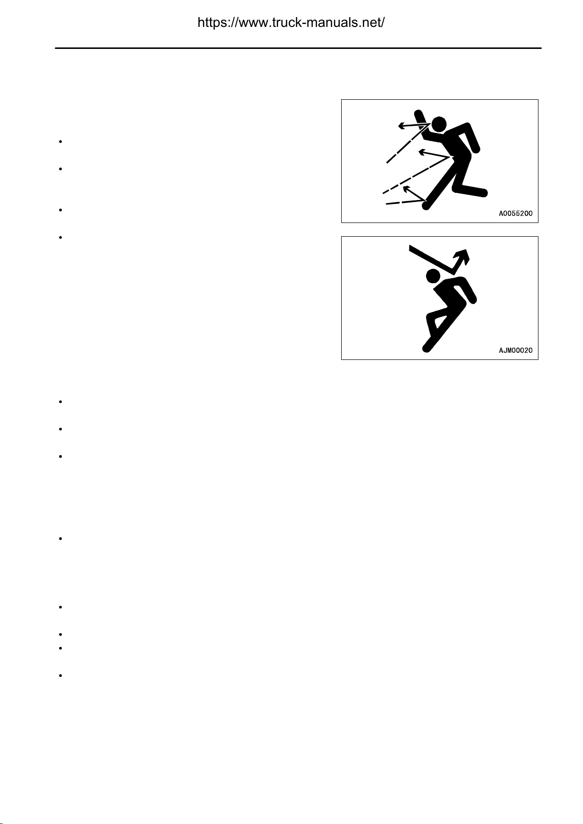
If there is any leakage from the piping or hoses, the surrounding
area will be wet, so check for cracks in the piping and hoses and
for swelling in the hoses.
When carry out inspection, wear safety glasses and leather
gloves.
There is a hazard that high-pressure oil leakingfrom small holes
may penetrate your skin or cause blindness if it contacts your
eyes directly. If you are hit by a jet of high-pressureoil and suffer
injury to your skin or eyes, wash the place with clean water, and
consult a doctor immediately for medical attention.
SAFETY
HANDLING HIGH-PRESSURE HOSES, PIPING
If oil or fuel leaks from high-pressure hoses, it may cause fire or defective operation, which may lead to serious
injury. If any loose bolts are found, stop work and tighten to thespecified torque. If any damaged hoses are found,
stop operations immediately and contact your Komatsu distributor.
Replace the hose if any of the following problems are found.
Damaged or leaking hydraulic fitting.
Frayed or cut covering or exposed reinforcement wire layer.
Covering swollen in places.
Twisted or crushed movable portion.
Foreign material embedded in covering.
WASTE MATERIALS
To prevent pollution, pay careful attention to the method of disposing of waste materials.
Always put oil drained from your machine in containers. Never
drain oil directly onto the ground or dump into the sewage
system, rivers, the sea, or lakes.
Obey appropriate laws and regulations when disposing of
harmful objects such as oil, fuel, coolant, solvent, filters, and
batteries.
MAINTENANCE OF AIR CONDITIONER
If air conditionerrefrigerant gets into your eyes, it may cause blindness;if it touches your skin, it may cause frostbite.
Never touch refrigerant.
2 - 30

.
SAFETY
COMPRESSED AIR
When carrying out cleaning with compressed air, there is a hazard of serious injury caused by flying particles.
When using compressed air to clean elements or the radiator, always wear safety glasses, dust mask, gloves,
and other protective equipment.
PERIODIC REPLACEMENT OF SAFETY-CRITICAL PARTS
In order for the machine to be operated safely for a long time, it is necessary to add oil and to carry out service
and maintenance at periodic intervals. In order to further increase safety, components with a strong relationship
to safety, such as hoses and seat belts, must be replaced at periodic intervals.
Replacement of safety-critical parts: See "PERIODIC REPLACEMENT OF SAFETY CRITICAL PARTS (PAGE
4-13)".
The material of these components naturally changes over time, and repeateduse causes deterioration, wear, and
fatigue. As a result, there is a hazard that these components may fail and cause serious injury or death. It is
difficult to judge the remaining life of these components from external inspection or the feeling when operating,
so always replace them at the specified interval.
Replace or repair safety-critical parts if any defect is found, even when they have not reached the time specified
interval.
PRECAUTIONS FOR MAINTENANCE
2 - 31

.
PRECAUTIONS WITH TIRES
SAFETY
PRECAUTIONS WITH TIRES
HANDLING TIRES
If tires or rims are handled mistakenly, there is danger that the tire
may explode or be damaged, or that the rim may fly off and cause
serious injury or death.
To maintain safety, always do as follows.
Maintenance, disassembly, repair, and assembly of the tires
and rims requires special equipment and special technology, so
always ask your Komatsu distributor to carry out these
operations.
Use only the specified tires and inflate them to the specified
pressure.
Suitable inflation pressure: see "SELECTION AND
INSPECTION OF TIRES (PAGE 4-34)".
When pumping up the tires, check that no other person is
standing near the tire, and install an air chuck with a clip that can
be secured to the air valve.
To prevent the tire inflation pressure from becoming too high,
measure the pressure from time to time with an air gauge while
pumping up the tire.
If the tire pressure goes down abnormally or the rim parts do not
fit the tire, there is a problem with the tire or rim parts. Always
contact your Komatsu distributor for repairs.
If the rim parts are not fitted properly when the tire is being pumped up, there is danger that the rim parts may fly
off, so set up a protective fence around the tire, and do not stand directly in front of the rim. Stand beside the tread
when pumping up the tire.
Do not adjust the tire inflation pressure immediately after traveling at high speed or carrying out operationsunder
heavy load.
Never carry out welding or light a fire near the tire.
PRECAUTIONS WHEN STORING TIRE
Tires for construction equipment are extremely heavy, so trying to
hold the tire may lead to serious injury.
As a basic rule, store the tires in a warehouse which
unauthorized persons cannot enter.
If the tires must be stored outside, always erect a fence and put
up "No Entry" signs.
Stand the tire on level ground, and block it securely so that it
cannot roll or fall over if any person should touch it.
Do not lay the tire on its side. This will deform the tire and cause
it to deteriorate.
If the tire should fall over, do not attempt to stop it. Get out of the
way quickly.
2 - 32

.
3 - 1

.
GENERAL VIEW
OPERATION
GENERAL VIEW
GENERAL VIEW OF MACHINE
(1)
(2)
(3)
Dump body
Rear wheel
Front wheel
(4)
Turn signal light
(5)
Head lamp
3 - 2

.
OPERATION
GENERAL VIEW
GENERAL VIEW OF CONTROLS AND GAUGES
Safety lock
(1)
Dump lever
(2)
Lamp switch, Turn signal lever, Dimmer switch
(3)
Steering wheel
(4)
Machine monitor
(5)
Retarder control lever
(6)
Cigarette lighter
(7)
Shift lever
(8)
Parking brake valve lever
(9)
Shift limiter switch
(10)
Power mode selector switch (if equipped)
(11)
Emergency brake lever
(12)
Emergency steering switch
(13)
Message display for PMC (if equipped)
(14)
Engine emergency stop switch
(15)
Accelerator pedal
(16)
Brake pedal
(17)
Differential lock pedal (if equipped)
(18)
3 - 3

.
GENERAL VIEW
Enlargement of machine monitor
OPERATION
Caution/pilot lamp bulb check switch
(1)
Starting switch
(2)
Preheating switch
(3)
AISS LOW switch
(4)
Panel dimmer switch
(5)
Hazard lamp switch
(6)
Front brake cut-off switch
(7)
Exhaust brake switch
(8)
3 - 4

.
OPERATION
EXPLANATION OF COMPONENTS
EXPLANATION OF COMPONENTS
The following is an explanation of devices needed for operating the machine.
To perform suitable operations correctly and safely, it is important to completely understand methods of operating
the equipment, and the meanings of the displays.
MACHINE MONITOR
Meter display portion
User code display
A:
Caution items
B:
Emergency stop item
C:
NOTICE
When the starting switch is turned to the ON position before the engine is started, all the monitors, gauges, and the central
warning lamp will light up for approx. 3 seconds, and the alarm buzzer will sound for approx. one second. When this happens, the
speedometer will display 88.
If no monitor lamp lights up, then there is probably a failure or disconnection in that circuit, therefore contact your Komatsu
distributor to have the circuit checked.
When the starting switch is at the ON position, if the shift lever is not at the neutral position, then the transmission shift lever
position pilot lamp (1) and the central warning lamp will flash and the alarm buzzer will continue to sound intermittently. At this
time, when the lever is placed in neutral, letter N is displayed, the central warning lamp goes out and the buzzer stops.
Checking for blown caution lamp or pilot lamp bulbs
Turn the starting switch to the ON position before starting the engine, press bulb check switch (2) and check that
no caution lamp or pilot lamp bulbs are blown.
If any lamp does not light up, the bulb is probably blown, so replace the bulb.
If the lamp does not light up even when the bulb is replaced, there is probably a failure or disconnection, so please
contact your Komatsu distributor to have the circuit checked.
D:
Mechatronic caution lamp portion
E:
Central warning lamp
F:
3 - 5

.
EXPLANATION OF COMPONENTS
USER CODE DISPLAY
If any failure occurred on the machine or if the operation needs to be changed or if checks and maintenance are
required, the user code display (1) shows the user code indicating appropriate corrective action. At this time, the
monitor related to the abnormal area lights up or flashes, and the central warning light flashes.
OPERATION
(1) User code display
WARNING
If user code 02 or 04 is displayed, stop the machine immediately. See "SERVICE CODE (PAGE 3-118)", and check the service code
number. Contact Komatsu distributor, telling them the service code number, for repair.
If letter "E-" and any user code of "01 to 07" is displayed in turn at the upper right of the liquid crystal display on the
monitor panel, stop the machine once. Then, take the corrective action as follows after checking user code (1).
User code
02: Park the machine at a safe location and contact your Komatsu distributor.
04: Carry out an emergency stop. Stop the engine and contact your Komatsu distributor.
01: Carry out checks and maintenance according to the Operation and Maintenance Manual.
03: Operate the machine keeping the engine at low revolution and low travel speed.
05: Stop the machine. Run the engine at a mid-range speed under no load.
06: Restart the engine. Idle the engine for a while.
07: Do not raise the dump body.
If the user code is displayed again even after taking the corrective action shown above when the user code 01,
03, 05, 06, or 07 is displayed, check the sevice code.
3 - 6

.
OPERATION
CAUTION ITEMS
EXPLANATION OF COMPONENTS
CAUTION
If any of the warning monitors lights up, carry out the inspection and maintenance of the appropriate item as soon as possible.
If it is left without the inspection and maintenance, it will lead to the trouble or failure.
If there is any abnormallity for the caution items, the monitor for the corresponding abnormal area lights up.
Transmission filter clogging
Battery charge
(1)
Emergency steering
(2)
Parking brake
(3)
Dump body actuation caution
(4)
BATTERY CHARGE
This (1) notifies the operator of any abnormality in the charging
system when the engine is running. If it lights up and
simultaneously displays user code 01, check the charging circuit.
(5)
Fuel level
(6)
Maintenance caution lamp (if equipped)
(7)
3 - 7

.
EXPLANATION OF COMPONENTS
EMERGENCY STEERING
This (2) lights up when the emergency steering is actuated.
If any abnormality should occur in the steering oil pressure circuit
when the machine is traveling, the auto emergency steering is
actuated and the related lamp lights up.
PARKING BRAKE
This (3) lights up when the parking brake is applied.
It goes on and out respectively responding to the parking brake
lever shifting of PARK/TRAVEL.
OPERATION
DUMP BODY ACTUATION CAUTION
This monitor (4) lights up when the dump body control lever is at
any position other than FLOAT or when the body is lifted. Always
set the lever to the FLOAT position and lower the body during
traveling.
TRANSMISSION FILTER CLOGGING
This monitor (5) notifies the operator that the transmission filter is
clogged. If it lights up anddisplays action code01 at the same time,
replace the transmission filter.
3 - 8

.
OPERATION
FUEL LEVEL
This monitor (6) flashes when the level of the fuel in the fuel tank
goes below 170 liters (44.88 US gal).
If it flashes, check the fuel level and add fuel.
MAINTENANCE CAUTION LAMP
(If equipped)
If the machine is in any of the following conditions, this lamp will
light up.
If it lights up and displays user code 01 at the same time, carry out
check, replenishment or replacement.
EXPLANATION OF COMPONENTS
Insufficient oil in the front brake oil tank
Insufficient oil in the transmission case
Insufficient oil in the hydraulic oil tank
Clogging of the transmission filter (on the tank side)
Clogging of the full flow filter (the engine oil filter)
Clogging of the hydraulic oil filter
Wear of the rear brake disc (right hand)
Wear of the rear brake disc (left hand)
Drop of the battery electrolyte level
Insufficient oil in the engine oil pan
Clogging of the air cleaner
3 - 9

.
EXPLANATION OF COMPONENTS
EMERGENCY STOP ITEM
OPERATION
CAUTION
If any of these monitor lights up or flashes, stop the engine immediately or put the engine in low idling, then check the
corresponding area and carry out the action.
If the abonormaliy is found in the emergency items, the waring buzzer sounds and the monitor corresponds to the
abnormal section lights up or flashes, and the central warning light flashes.
Engine oil pressure
Air pressure
(1)
Engine water temperature
(2)
Torque converter oil temperature
(3)
Retarder oil temperature
(4)
Radiator water level
(5)
AIR PRESSURE
This monitor (1) warns the operator that the air pressure inside the
air tank has dropped. If it flashes and displays the user code "05"
at the same time, stop the machine, run the engine under no load
at a mid-range speed, and wait until the lamp goes out.
(6)
Angle warning
(7)
Rear brake caution lamp
(8)
Steering oil temperature
(9)
3 - 10

.
OPERATION
ENGINE WATER TEMPERATURE
This (2) warns the operator that the engine cooling water
temperature has risen.
For the machine equipped with an electronic governor (if
equipped), the engine output is automatically limited.
If it flashes and displays user code 05 at the same time, stop the
machine and run the engine under no load at a mid-range speed
until the engine water temperature gauge enters the green range.
TORQUE CONVERTER OIL TEMPERATURE
This monitor (3) warns the operator that the torque converter oil
temperature has risen.
If it flashes and displays user code "05" at the same time, stop the
machine and run the engine under no load at a mid-range speed
until the torque converter oil temperature gauges enters the green
range.
EXPLANATION OF COMPONENTS
RETARDER OIL TEMPERATURE
This monitor (4) warns the operator that the retarder oil
temperature has risen.
If it flashes and displays user code "05" at the same time, stop the
machine, place the shift lever at the N (neutral) position, then run
the engine under no load at a mid-range speed until the warning
lamp goes out.
RADIATOR WATER LEVEL
This (5) warns the operator that the radiator water level has
dropped.
If it lights up and displays user code 01 at the same time, stop the
engine, check the level of the cooling water in the radiator, and add
the water.
3 - 11

.
EXPLANATION OF COMPONENTS
ENGINE OIL PRESSURE
This (6) warns the operator that the engine lubricating oil pressure
has dropped.
If it lights up and displays user code 04 at the same time, stop the
machine safely. Then, stop the engine and carry out inspection.
The lamp lights up if the engine lubricating oil pressure goes below
the specified value when the engine is running,
If the engine is not running, the lamp does not light up.
ANGLE WARNING
When the dump body is raised, this monitor (7) warns the operator
that the machine has tilted beyond the safety range to the left or
right.
If it lights up and displays action code "07" at the same time, lower
the body and move the machine to a safe, stable place.
OPERATION
REAR BRAKE CAUTION LAMP
This monitor (8) lights up if the brake oil pressure drops under the
normal value.
If it lights up and display user code "04" at the same time,
immediately check the rear brake system.
After checking and repairing, depress the rod for the overstroke
sensor on the brake chamber.
If depressing is not carried out, the rear brake caution lamp will
continue to light up.
STEERING OIL TEMPERATURE
This monitor (9) warns the operator that the steering oil
temperature has risen.
If it lights up and displays user code "05" at the same time, stop the
machine, place the shift lever at the N (neutral) position, then run
the engine under no load at a mid-range speed until the warning
lamp goes out.
3 - 12

.
OPERATION
METER DISPLAY PORTION
PILOT DISPLAY PORTION
When starting switch is ON, the pilot display lights up when display items are functioning.
EXPLANATION OF COMPONENTS
High beam
Preheating monitor
(1)
Exhaust brake pilot
(2)
Rear brake pilot (retarder)
(3)
Differential lock pilot (if equipped)
(4)
Lockup pilot lamp
(5)
Shift limiter pilot lamp
(6)
PREHEATING MONITOR
This lamp lights up when the electrical heater for preheating the
engine is being actuated.
(7)
Turn signal pilot lamp
(8)
Shift indicator (with lockup display)
(9)
Transmission shift lever position pilot lamp
(10)
Auto suspension mode display lamp
(11)
Power mode display lamp (if equipped)
(12)
3 - 13

.
EXPLANATION OF COMPONENTS
EXHAUST BRAKE PILOT
This pilot lamp (2) lights up when the exhaust brake is actuated.
REAR BRAKE PILOT (Retarder)
This pilot lamp (3) lights up when the foot brake is depressed or the
retarder control lever is pulled, and the rear brake is applied.
OPERATION
DIFFERENTIAL LOCK PILOT
(If equipped)
This pilot lamp (4) lights up when the differential lock pedal (if
equipped) is depressed and the differential lock is actuated.
LOCKUP PILOT LAMP
This pilot lamp (5) lights up when the torque converter lockup is
engaged and the transmission is shifted to direct drive.
3 - 14

.
OPERATION
SHIFT LIMITER PILOT LAMP
This pilot lamp (6)lights up when the shift limiter switch is actuated.
HIGH BEAM
This monitor (7) lights up when the head lamps are set to high
beam.
EXPLANATION OF COMPONENTS
TURN SIGNAL PILOT LAMP
This pilot lamp (8) flashes at the same time as the turn signal lamp
flashes.
SHIFT INDICATOR
This monitor (9) displays the transmission shift range (speed
range).
When the key was turned ON, if the shift lever is operated, it will
display "2" at the lever position "D", "1" at the "5" - "L" position, and
"R" at the R position even if the engine is stopped.
3 - 15

.
EXPLANATION OF COMPONENTS
TRANSMISSION SHIFT LEVER POSITION PILOT LAMP
This monitor (10) indicates the position of the transmission shift
lever.
AUTO SUSPENSION MODE DISPLAY LAMP
This monitor (11) displays the suspension mode, when the
machine is equipped with the suspension controller.
An automatic suspension system is mounted which automatically
switches the damping characteristics of the suspension according
to the size of the load, use of the brake, operation of the steering,
and operation of the dump control.
Normally it is set to the soft mode when the dump truck is traveling
empty and to the medium mode when it is traveling loaded. When
the foot brake is operated or the machine is suddenly turned,or the
dump control is operated, the suspension mode is switched to
insure the stability of the machine to the front and rear, and left and
right.
OPERATION
H : Hard mode
M : Medium mode
S : Soft mode
POWER MODE DISPLAY LAMP
(If equipped)
This monitor (12) displays the power mode.
Select the mode with the power mode switch.
3 - 16

.
OPERATION
METERS
EXPLANATION OF COMPONENTS
Speedometer
(1)
Engine tachometer
(2)
Service meter
(3)
Odometer
(4)
Fuel gauge
(5)
SPEEDOMETER
This meter (1) indicates the travel speed of the machine.
Air pressure gauge
(6)
Engine water temperature gauge
(7)
Torque converter oil temperature gauge
(8)
Retarder oil temperature gauge
(9)
3 - 17

.
EXPLANATION OF COMPONENTS
ENGINE TACHOMETER
This meter (2) indicates the speed of the engine.
While operating the machine, if the red range lights up,
simultaneously the warning buzzer sounds and the central warning
lamp flashes, then operate the machine while lowering the engine
speed and the traveling speed.
SERVICE METER
This meter (3) shows the total hours of operation of the machine.
If the engine is running, the service meter will advance even if the
machine is not moving.
The meter advances by 1 for every one hour of operation,
regardless of the engine speed.
OPERATION
ODOMETER
This (4) indicates the distance traveled in kilometers.
FUEL GAUGE
This gauge (5) indicates the amount of fuel in the fuel tank.
The green range should be lighted up during operation.
If only the red range remains lighted during operation, it indicates
that there is less than 120 liters (31.68 US gal) of fuel remaining in
the tank, so check and add fuel.
3 - 18

.
OPERATION
AIR PRESSURE GAUGE
This gauge (6) indicates the air pressure inside the air tank.
The green range should be lit up during operation.
If the red range lights up during operation, the alarm buzzer will
sound, the central warning lamp will flash, and the air pressure
monitor lamp will also flash at the same time.
If this happens, stop the machine, raise the enginespeed, and wait
until the green range lights up.
REMARK
If the air pressure drops further, the parking brake is automatically
applied.
ENGINE WATER TEMPERATURE GAUGE
This gauge (7) indicates the engine cooling water temperature.
The green range should be lighted up during operation.
If the red range lights up during operation, the alarm buzzer will
sound, the central warning lamp will flash, and the engine water
temperature monitor lamp will flash at the same time.
If this happens, stop the machine, run the engine under no load at
a mid-range speed, and wait until the green range lights up.
If the red range lights up, the engine output of the machine
equipped with an electronic governor is automatically limited.
EXPLANATION OF COMPONENTS
TORQUE CONVERTER OIL TEMPERATURE GAUGE
This gauge (8) indicates the torque converter oil temperature.
The green range should be lit up during operation.
If the red range lights up during operation, the alarm buzzer will
sound, the central warning lamp will flash, andthe torque converter
oil temperature monitor lamp will flash at the same time. If this
happens, stop the machine, run the engine under no load at a
mid-range speed, and wait until the green range lights up.
RETARDER OIL TEMPERATURE GAUGE
This gauge (9) indicates the retarder cooling oil temperature.
The green range should be lit up during operation.
If the red range lights up during operation, the alarm buzzer will
sound, the central warning lamp will flash, and the retarder oil
temperature monitor lamp will flash at the same time. If this
happens, stop the machine, run the engine under no load at a
mid-range speed, and wait until the green range lights up.
3 - 19

.
EXPLANATION OF COMPONENTS
MECHATRONIC CAUTION LAMP PORTION
If an abnormality is detected in the mechatronics-related parts of the control system, the monitor lamp and the
central warning lamp light up and the alarm buzzer sounds intermittently. Stop the machine, then take appropriate
corrective action according to the user code.
OPERATION
(1)
Engine (Mechatronics-related)
(2)
Automatic transmission (Mechatronics-related)
ENGINE
(Mechatronics-related)
If an abnormality is detected in the mechatronics-related parts of
the engine control system, this lamp (1) flashes to warn of the
abnormality.
(3) Mechatronics-related parts
(Excluding 1. and 2. above)
3 - 20

.
OPERATION
AUTOMATIC TRANSMISSION
(Mechatronics-related)
If an abnormality is detected in the mechatronics- related parts of
the transmission control system, this lamp (2) flashes to warn of
the abnormality.
MECHATRONICS-RELATED PARTS
(Excluding 1. and 2. above)
If an abnormality is detected in the mechatronics-related parts of
the control system other than those of the engine and
transmission, this lamp (3) flashes to warn of the abnormality.
EXPLANATION OF COMPONENTS
CENTRAL WARNING LAMP
If the machine is in the following condition, this lamp will flash.
When an abnormality has occurred in any of B caution items.
When the abnormalities has occurred refered to "CAUTION
ITEMS (PAGE 3-7)".
If the machine is in the following condition, this lamp will flash, and
at the same time, the alarm buzzer will sound intermittently.
When an abnormality has occurred in any of "EMERGENCY
STOP ITEM (PAGE 3-10)".
When "MECHATRONIC CAUTION LAMP PORTION (PAGE
3-20)" flashes.
If the parking brake is applied, but the shift lever is not at neutral.
When the dump lever is not at the FLOAT position and the shift lever is not at neutral.
When engine tachometer red range lights up.
3 - 21

.
EXPLANATION OF COMPONENTS
OPERATION
SWITCHES
Starting switch
(1)
Lamp switch
(2)
Turn signal lever
Dimmer switch
Caution/pilot lamp bulb check switch
(3)
Exhaust brake switch
(4)
Front brake cut-off switch
(5)
Hazard lamp switch
(6)
Night lighting dimmer switch
(7)
AISS LOW switch
(8)
Preheating switch
(9)
Power mode selector switch
(10)
Emergency steering switch
(11)
Emergency brake lever
(12)
Shift limiter switch
(13)
Parking brake valve lever
(14)
Engine emergency stop switch
(15)
Cigarette lighter
(16)
Horn button
(17)
Wiper switch
(18)
Room lamp switch
(19)
3 - 22

.
OPERATION
STARTING SWITCH
This switch (1) is used to start or stop the engine.
OFF position
At this position, the starting switch key can be inserted or removed.
When the key is turned to this position, all the electric circuits are
switched off and the engine stops.
ON position
In this position, electric current flows in the charging and lamp
circuits.
Keep the starting switch key at the ON position while the engine is
running.
When turning the starting switch ON or OFF, if the starting switch is held at a position between ON and OFF, the
controller may detect this as a problem. If this happens, return the starting switch to the OFF position, then operate
it as usual to the ON position.
EXPLANATION OF COMPONENTS
START position
This is the position to start the engine. Hold the key at this position while cranking. Release the key immediately
after the engine has been started. The key will return to the ON position when released.
LAMP SWITCH
This (2) lights up the head lamps, side clearance lamps, tail lamps,
machine monitor lighting, and rear lamps.
(a) position: OFF
(b) position: Side clearance lamps, tail lamps, rear lamps,machine
monitor lighting light up
(c) position: The head lamps light up in addition to the lamps in the
(b) position
The lamp switch can be operated regardless of the position of the
lever.
TURN SIGNAL LEVER
This lever (2) operates the turn signal lamp.
(a)Right turn: Push the lever forward
(b)Left turn: Push the lever back
When the lever is operated, the turn signal pilot lamp also flashes.
The lever is automatically returned when the steering wheel is
turned back. If the lever does not return, move it by hand.
3 - 23

.
EXPLANATION OF COMPONENTS
DIMMER SWITCH
This (2) is used to switch the head lamps between high beam and
low beam.
(a) Low beam
(b) High beam
CAUTION/PILOT LAMP BULB CHECK SWITCH
Press this switch (3) when the starting switch is at the ON position
to check for any blown bulbs.
OPERATION
EXHAUST BRAKE SWITCH
This switch (4)shows the operating condition of the exhaust brake.
If it is pushed once, it lights up; and it goes off when it is pushed
again.
OFF position (Light is off):
The exhaust brake is actuated when the brake pedal is depressed
or the retarder control lever is operated if the torque converter is in
the lockup condition.
ON position (Light is on):
The exhaust brake is actuated when the accelerator pedal is
released if the torque converter is in the lockup condition.
3 - 24

.
OPERATION
FRONT BRAKE CUT-OFF SWITCH
EXPLANATION OF COMPONENTS
WARNING
When traveling on icy roads, on snow, or on other slippery road surfaces, set the front brake cut-off switch to the ON position
and travel slowly at a safe speed.
If the front brake cut-off switch is set to the OFF position, it becomes dangerously difficult to control the steering when
traveling under the abovementioned conditions.
This switch (5) switches the braking method according to the road
surface conditions.
If the switch is pressed, the lamp lights up, the front brake cut
function is actuated, and the brakes are not applied to the front
wheels.
If the switch is pressed again, the lamp goes out and the front
brake cut function is canceled.
OFF position (Light is off.):
When the brake pedal is depressed, the brakes are applied to both
the front and rear wheels.
ON position (Light is on.):
When the brake pedal is depressed, the front brakes are not
applied. The brakes are applied only to the rear wheels.
When traveling at high speed, on a road surface that has been properly watered, set the front brake cut-off switch
to OFF position (lamp off), and normally use the retarder control lever to control the travel speed (retarder braking
is applied only to the rear wheels).
To control the machine whenever emergencyaction is needed, such as when the machine slips to the side or when
the machine has to be stopped suddenly, use the brake pedal to operate the brakeson the front wheels to give extra
braking force.
HAZARD LAMP SWITCH
This switch (6) flashes the left- and right-hand turn signal lamps.
When the switch is turned on, the turn signal pilot lamp flashes at
the same time. If the starting switch is OFF, the turn signal pilot
lamp does not flash.
3 - 25

.
EXPLANATION OF COMPONENTS
NIGHT LIGHTING DIMMER SWITCH
This switch (7) is used to adjust the brightness of the monitor panel
lighting and pilot lamps. Turn to the right to make the lighting
brighter and turn it to the left to make the lighting dimmer.
AISS LOW SWITCH
AUTO and LOW speed can be freely switched to each other with
AISS LOW switch (8). Use each position as follows.
If the switch is depressed, it lights up, and if it is depressed once
again, the light goes off.
OFF position (Light is off): AUTO position
At normal operation
ON position (Light is on): Low speed position
When the delicate start and operation is
needed like putting the machine into
garage
OPERATION
If the switch is at AUTO position:
When stopping the machine, by setting either parking brake or retarder brake at ON position, idling is set at low
1.
speed. When starting, by setting the parking brake at OFF position, idling is set at high speed.
2. Detecting the water temperature, idle is set at high speed automatically under the low temperature condition,
and the warm-up time is shortened.
PREHEATING SWITCH
This switch (9) operate an electric heater to heat the intake air for
the engine. If it is pushed, it lights up and perform preheating. If it
is released, it returns to the original position.
OFF position (Light is off): If the ambient temperature is below
approx. - 5°C (23°F), preheating is
carried out automatically according to
the ambient temperature.
ON position (Light is on): Preheating is carried out.
Press this switch if the engine does not start when only automatic
preheating is carried out or when post-heating is required after the
engine is started.
When the switch is released, it will return automatically to the
automatic preheating position.
3 - 26

.
OPERATION
POWER MODE SELECTOR SWITCH
The power mode switch (10) can be switched to allow the machine
to travel economically in a way suited to the operating conditions.
If depressed once, it lights up; if depressed once again, the light
goes off.
OFF position: High power (general operations)
This is used for general operating conditions.
ON position: economy (traveling in flat areas)
This position is used when the emphasis is on
reducing fuel consumption, such as when traveling
on flat ground where maximum output is not needed.
EMERGENCY STEERING SWITCH
This switch (11) is used to actuate the emergency steering pump.
When the switch is pressed, the emergency pump is actuated to
make it possible to operate the steering.
When the switch is ON, the pilot lamp (red) inside the switch lights
up.
The emergency steering pump can be used for a maximum of 90
seconds.
When using the emergency steering, travel at a speed of less than
5 km/h (3.1 MPH).
When the emergency steering is actuated, it is possible to use the
dump lever to raise the dump body.
EXPLANATION OF COMPONENTS
Automatic emergency steering will be actuated automatically in the following cases:
When hydraulic pump for steering has trouble
When engine has stopped during operation
When the automatic emergency steering is actuated, stop the machine promptly and perform inspection.
If the key switch is turned ON when the machine is stopped and the parking brake switch is OFF, the auto
emergency steering is actuated after 1 second, so turn the parking brake switch to the ON (PARKING) position.
EMERGENCY BRAKE LEVER
This lever (12) is used to actuate the emergency brake.
ON (applied): Emergency brake actuated
TRAVEL: Emergency brake released
If the pressure in the air tank drops below 0.22 MPa (2.2 kgf/cm2,
31.24 PSI), the emergency brake is automatically applied.
If the emergency brake is applied because of a failure in the air
system, the central warning lamp flashes and the alarm buzzer
sounds.
For details of releasing the brake when the emergency brake has
been applied because of a failure in the air system, see "RELEASE
METHOD WHEN PARKING BRAKE AND EMERGENCY BRAKE
HAVE BEEN ACTUATED IN EMERGENCY (PAGE 3-107)"
3 - 27

.
EXPLANATION OF COMPONENTS
SHIFT LIMITER SWITCH
This switch (13) is used to limit the maximum speed range when
the transmission shift lever is in the D or L range. If the switch is
depressed, it lights up, and the shifit limiter function get actuated;
consequently the maximum speed for D range is limited to F6, and
the speed for L range is limited to F1 only. If the switch is
depressed again, the light goes away.
Light-off position: D range F2 - F7
L range F1 - F2
Light-on position: D range F2 - F6
L range F1
PARKING BRAKE VALVE LEVER
OPERATION
WARNING
When parking or leaving the machine, always apply the parking brake.
During loading operations, do not apply the parking brake. Pull the retarder lever to apply the brake.
This lever (14) is used to actuate the parking brake valve.
PARKING: Parking brake actuated
TRAVEL: Parking brake is released.
When the lever is set to the PARKING position, the parking brake
pilot lamp lights up.
When the lever is set to the PARKING position, if the gear shift
lever is at any position other than N, the central warning lamp will
flash and the alarm buzzer will sound.
If the air pressure drops and goes below 0.22MPa(2.2kgf/cm2, 31.24PSI), the emergency brake and parking brake
are automatically applied.
For details of releasing the brakewhen the emergencybrake has beenapplied because of a failure in the air system,
see "RELEASE METHOD WHEN PARKING BRAKE AND EMERGENCY BRAKE HAVE BEEN ACTUATED IN
EMERGENCY (PAGE 3-107)"
ENGINE EMERGENCY STOP SWITCH
NOTICE
This switch must not be used for stopping the engine under normal
conditions. When the engine has completely stopped, return the switch to
the ON (TRAVEL) position.
Use this switch (15) if the engine will not stop even when the
starting switch is turned to the OFF position.
3 - 28

.
OPERATION
CIGARETTE LIGHTER
This (16) is used to light cigarettes.
When the cigarette lighter is pushed in, it will return to its original
position after several seconds, so pull it out and use it to light your
cigarette.
HORN BUTTON
When the horn button (17) in the center of the steering wheel is
pressed, the horn will sound.
EXPLANATION OF COMPONENTS
WIPER SWITCH
This switch (18) is used to operate the wiper.
INT position: Wiper moves intermittently
OFF
LOW position: Wiper moves at low speed
HI position: Wiper moves at high speed
When the switch is pressed, washer fluid is sprayed out.
ROOM LAMP SWITCH
This (19) is used to switch the room lamp on or off.
(a) OFF
(b) ON
3 - 29

.
EXPLANATION OF COMPONENTS
OPERATION
CONTROL LEVERS AND PEDALS
Brake pedal
(1)
Accelerator pedal
(2)
Shift lever
(3)
Safety lock
(4)
BRAKE PEDAL
This pedal (1) is used to apply the wheel brakes.
Dump lever
(5)
Retarder control lever
(6)
Differential lock pedal (if equipped)
(7)
3 - 30

.
OPERATION
ACCELERATOR PEDAL
This pedal (2) is used to adjust the engine speed.
It can control freely the engine between the low idle and the full
throttle.
GEAR SHIFT LEVER
The gear range can be selected with this lever (3) to match the
travel conditions.
EXPLANATION OF COMPONENTS
D position:
This is used for normal travel.
If the lever is placed in this position, the transmission is shifted
automatically from 2nd (torque converter drive) to 7th (direct drive)
to match the travel speed of the machine.
If the dump body is raised, the speed rangeis fixed at 2nd when the
shift lever is at D position. Always lower the dump body when
traveling.
The maximum speed in D position is 65 km/h (40.4 MPH).
R position:
This is used when traveling in reverse.
This position uses the torque converter drive.
The machine cannot travel in reverse if the dump lever is not at the FLOAT position. Set the dump lever to the
FLOAT position before moving the shift lever to the R position.
5 - L position:
These positions are used in places where it is difficult to travel at high speed, or when traveling on soft ground, or
when starting the machine off on a slope when it is loaded. They are also used when going downhill if it is needed
to use the braking force of the engine.
The speed ranges for each position are as follows.
Position Speed range Max. speed (km/h (MPH))
5 1st torque converter - 5th direct 36 (22.4)
4 1st torque converter - 4th direct 27 (16.8)
3 1st torque converter - 3rd direct 20 (12.4)
L 1st torque converter - 2nd direct 15 (9.3)
If the dump body is raised, it is impossible to shift up from 1st. Always lower the dump body when traveling.
When operating the shift lever, be sure to set it in position securely.
If the lever is not placed in position properly, the shift position display on the panel may go out and the transmission
warning monitor lamp may light up.
3 - 31

.
EXPLANATION OF COMPONENTS
Before shifting between forward and reverse, stop the machine completely and then run the engine at low idle.
When starting the engine, if the gear shift lever is not at the N position, the engine will not start.
When the starting switch is turned to the ON position, if the shift lever is not at the N (neutral) position, the
transmission shift lever position pilot lamp and the central warning lamp will flash and the alarm buzzer will sound.
If shift lever is not at N (neutral) position when the parking brake is applied, the central warning lamp will flash and
the alarm buzzer will sound.
When the dump lever is not at the FLOAT position and when the dump body has risen, if the shift lever is not at the
N (neutral) position, the central warning lamp will flash and the alarm buzzer will sound.
The shift lever must not be returned to the N (neutral) position while traveling.
Release the accelerator pedal and run the engine at low idle when moving the shift lever from the N (neutral) position
to the forward or reverse position.
OPERATION
When moving the gear shift lever from the N (neutral) position to the R (reverse) position or from the D positions to
position 5 (or other lower position), press the lock button on the gear shift lever before moving it.
SAFETY LOCK
WARNING
When raising the dump body to inspect the machine, always place the dump lever at the HOLD position, apply the lock, and then
use the safety pins.
This device (4) is used to lock the dump lever.
3 - 32

.
OPERATION
DUMP LEVER
EXPLANATION OF COMPONENTS
WARNING
To prevent damage to the dump body through vibration from the road surface, always lower the dump body and set at FLOAT
position before traveling.
This lever (5) is used to operate the dump body.
(a) RAISE
(b) HOLD: The dump body stops and is held in position.
(c) FLOAT: The dump body moves freely under external force.
(d) LOWER
For details, see "DUMP OPERATIONS (PAGE 3-88)".
RETARDER CONTROL LEVER
CAUTION
The retarder must not be used as a parking brake.
This lever (6) is used to operate the retarder, which applies the rear
wheel brake when going downhill.
The more the lever is pulled, the greater the braking force
becomes.
When the retarder is actuated, the rear brake pilot lamp lights up.
For details, see "TRAVELING DOWNHILL (PAGE 3-81)". When
leaving the operator's seat, always apply the parking brake.
DIFFERENTIAL LOCK PEDAL
(If equipped)
This pedal (7) is used to actuate the differential lock control.
When the pedal is depressed, the differential lock is actuated, and
when it is released, the differential lock is canceled.
See "USING DIFFERENTIAL LOCK (PAGE 6-21)" for the details.
3 - 33

.
EXPLANATION OF COMPONENTS
OPERATION
MECHATRONICS EQUIPMENT CONTROLLER
(1)
Transmission controller
(2)
Engine controller
(3) Suspension controller
TRANSMISSION CONTROLLER
A two-digit number followed by the service code is displayed in the inspection window of this controller (1) to identify
the location of the abnormality. When the condition is normal, "0.0" or "0.C" is displayed.
For the mothod of checking the service code when an abnormality occurs, see "TRANSMISSION CONTROLLER
(PAGE 3-119)".
ENGINE CONTROLLER
For this controller (2), the last two-digit number of the service code is displayed in the inspection window to identify
the location of the abnormality. When the condition is normal, "0.0" is displayed.
For the method to check the service code when the abnormality occurs, see "SERVICE CODE (PAGE 3-118)".
SUSPENSION CONTROLLER
For this controller (3), the last two-digit number of the service code is displayed in the inspection window to identify
the location of the abnormality. When the condition is normal, "0.0" is displayed.
For the method to check the service code when the abnormality occurs, see "SERVICE CODE (PAGE 3-118)".
3 - 34

.
OPERATION
EXPLANATION OF COMPONENTS
SAFETY PIN
WARNING
When raising the dump body to inspect the machine, always place the dump lever at the HOLD position, apply the lock, and then
use the safety pins.
This is a safety device for the dump body, and is used when
carrying out inspection or maintenance with the dump body raised.
Raise the dump body fully, insert safety pins (1). Always insert the
safety pins on both sides.
STOWING SAFETY PIN
Safety pins (1) are stowed in the towing bracket of the rear axle
housing.
DUST INDICATOR
This device indicates clogging of the air cleaner element.
When red piston (1) appears in the transparent part of this
indicator, the element is clogged. Immediately clean the element.
After cleaning, push indicator button (2) to return the red piston to
the original position.
3 - 35

.
EXPLANATION OF COMPONENTS
OPERATION
FUSES
WARNING
When replacing any fuse, always turn the power off (turn the starting switch to OFF).
When replacing the fuse, always use a fuse of the same capacity and type.
The fuses protect the electrical equipment and wiring from burning
out.
If the fuse becomes corroded, or white powder can be seen, or the
fuse is loose in the fuse holder, replace the fuse.
FUSE CAPACITY AND CIRCUIT NAME
Fuse box I
Fuse
No.
capacity
1 10A Car radio, car stereo
2 10A Horn switch
3 10A Cigarette lighter
4 20A Turn signal indicator lamp, fog lamp (if equipped)
5 10A Engine start relay, neutral relay
6 20A Head lamp (low beam), stop lamp, room lamp
720A
8 10A Backup lamp, backup buzzer
910A
10 10A
Head lamp (high beam), side clearance lamp,
tail lamp, night lighting
Ribon heater relay, front brake cut-off solenoid,
BCV relay solenoid
Overrun prevention solenoid, transmission
controller, exhaust brake solenoid
Circuit name
3 - 36

.
OPERATION
Fuse box II
Fuse
No.
capacity
11 10A Engine controller, governor cut relay
Electronic display panel, caution pilot lamp,
12 10A
13 5A
14 5A
15 20A Payload external display lamp (if equipped)
16 5A PMC (if equipped)
17 10A
18 10A
19 10A Emergency steering
20 10A Direct from battery (spare)
central warning lamp, buzzer, PMC (if equipped),
MOM( if equipped)
Suspension control solenoid,
suspension controller
Payload meter (if equipped),
payload relay (if equipped)
Start switch, radio back-up, emergency engine
stop solenoid (if equipped electronic governor),
engine stop motor
T/M controller, engine controller (if equipped),
PMC (if equipped)
Circuit name
EXPLANATION OF COMPONENTS
Fuse box III
Fuse
No.
capacity
21 10A AISS motor
22 20A Wiper motor, washer motor
23 20A Air conditioner blower motor
24 10A Air conditioner compressor
25 10A Spare
26 10A Spare
Circuit name
3 - 37

.
EXPLANATION OF COMPONENTS
OPERATION
CAR STEREO
(If equipped)
EXPLANATION OF COMPONENTS
Power switch/Volume
(1)
Auto-store/Preset scan button
(2)
Bass control knob
(3)
Treble control knob
(4)
Loudness button
(5)
Time/Radio display selector button
(6)
Tape eject button
(7)
Band display
(A)
Metal tape display
(B)
FM stereo reception display
(C)
Loudness display
(D)
3 - 38
Cassette door
(8)
Fast forward, rewind buttons
(9)
Preset buttons
(10)
Metal tape button
(11)
Manual tuning buttons
(12)
Seek tuning buttons
(13)
Band selector button
(14)
Tape direction display
(E)
Preset channel display
(F)
Time/Frequency display
(G)

.
OPERATION
POWER SWITCH/VOLUME
Turn this knob (1) to the right until it clicks to turn the power on.
Turn it further to increase the volume.
AUTO-STORE/PRESET SCAN BUTTON
Use this button (2) to actuate the preset scan and auto-store
functions.
Auto-store
Each time this button is pressed for more than 2 seconds while
in radio reception, this auto-store function automatically starts to
search for the desired station within a receivable band, and
memorize the frequency in the preset memory. During this
scanning process, the frequency shown in the right side of
display continues to change. This indicates that each frequency
is memorized in the auto-store.
EXPLANATION OF COMPONENTS
REMARK
The auto-store function cannot be used when the channel display
is flashing.
When the display is flashing, the preset scan function is being
used.
Preset scan
If this button is pressed for less than 0.5 second while in radio reception, programs from the six preset stations
in the same band will be broadcast one after another for 5 seconds each, starting from No. 1 through No. 6
stations consecutively.
When the desired station is found, press the button again. This stopsthe presetscan tuningprocess and switches
to ordinary broadcasting. The same process will be repeated continuously until the button is pressed again.
BASS CONTROL KNOB
Turn this button (3) to the left to reduce the low tones; turn it to the
right to emphasize the low tones.
Direction (a): Low tone reduced
Direction (b): Low tone emphasized
3 - 39

.
EXPLANATION OF COMPONENTS
TREBLE CONTROL KNOB
Turn this button (4) to the left to reduce the low tones; turn it to the
right to emphasize the high tones.
Direction (a): High tone reduced
Direction (b): High tone emphasized
LOUDNESS BUTTON
This button (5) is used when playing at low volume. It makes it
possible to hear more easily by emphasizing the low tone when the
low tones are weak.
Push button: Actuated (ON)
Push button again: Canceled (OFF)
OPERATION
TIME/RADIO DISPLAY SELECTOR BUTTON
This button (6) is used to switch between the "Radio/tape display"
and the "Time display".
Correcting the time
Press the button to set the time display.
(A) Correcting hour:
Keep the DISP button pressed and press the bottom (H) of
the TUNING button to correct the hour.
(B) Correcting minute:
Keep the DISP button pressed and press the top (M) of the
TUNING button to correct the minute.
3 - 40

.
OPERATION
TAPE EJECT BUTTON
This button (7) is used to stop the tape and to eject the cassette.
When this button is pressed, the tape is ejected and the radio
plays.
CASSETTE DOOR
Set the cassette with the exposed portion of the tape on the right
side and insert it through the cassette door (8).
EXPLANATION OF COMPONENTS
FAST FORWARD, REWIND BUTTONS
These buttons (9) are used to fast-forward or rewind the tape.
Fast-forward/rewind
If you press the button pointing in the same direction as the
lighted arrow indicating the direction of play, the tape will be
fast-forwarded; if you press the button pointing in the opposite
direction, the tape will rewind.
To stop the tape, lightly press the button that is not locked. The
fast-forward or rewind operation will be canceled.
If the fast forward and rewind buttons are pressed at the same
time, the tape will change sides.
PRESET BUTTONS
These buttons (10) are used to call up the broadcast station
frequencies preset in memory for each of buttons No. 1 to No. 6.
It is possible to preset 18 stations (FM: 12; AM: 6) with these
buttons.
3 - 41

.
EXPLANATION OF COMPONENTS
METAL TAPE BUTTON
(used also for preset button No. 5)
This button (11) is used when playing a metal or chrome tape. This
button is also used for preset button No. 5. When it is pressed,
"MTL" appears on the display.
MANUAL TUNING BUTTONS
These buttons (12) are used for manual tuning.
When "TUN ∧" button is pressed, the frequency goes up 9 kHz for
AM or 0.1 MHz for FM; when "TUN ∨" button is pressed, the
frequency goes down 9 kHz for AM or 0.1 MHz for FM.
If the button is pressed down and held, the frequency will change
continuously.
OPERATION
SEEK TUNING BUTTONS
These buttons (13) are used to seek tuning.
When the "SEEK UP" button is pressed, the search automatically
goes up; when the "SEEK DOWN" button is pressed, the search
automatically goes down.
When the next station that can be received is found, it
automatically stops.
BAND SELECTOR BUTTON
When this button (14) is pressed, the band is switched between
FM1, FM2, and MW (AM). The band is shown on the display.
3 - 42

.
OPERATION
METHOD OF OPERATION
METHOD OF SETTING PRESET BUTTONS
To listen to a preset station, use band selector button (1) to select
AM, FM1, or FM2, then press the preset switch number to listen to
the desired station.
It is possible to preset six AM stations and 12 FM stations (FM1: 6,
FM2: 6).
1. If you are playinga cassette, press the tape eject button to stop
the tape.
Select the station to be preset.
2.
Use band selector button (1) to select MW (AM), FM1, or FM2,
then use the manual tuning button to select the frequency of
the broadcasting station.
3. Press manual memory button (2) or seek tuning button (3).
Press preset button (4) of the number to be preset for 2
4.
seconds while the frequency display is being shown on the
display. (The preset channel and frequency are displayed and
the presetting is completed).
Repeat Steps 2 to 4 to preset other stations.
5.
EXPLANATION OF COMPONENTS
REMARK
Use Steps 2 to 4 also when changing the setting of a preset
switch to another station.
When the power is disconnected, such as when the battery is
replaced, all the settings are deleted, so preset the stations
again.
3 - 43

.
EXPLANATION OF COMPONENTS
MANUAL MEMORY BUTTON
Select the station to be preset with manual tuning button (1) or
seek tuning button (2), then keep button No.1 to button No.6 of
button (3) pressed for 2 seconds while the frequency is being
displayed to preset the station.
OPERATION
LISTENING TO RADIO
Turn the starting switch ON, then turn power switch (1) ON.
1.
2. Set band selector button (2) to AM or FM.
Select the station with the preset buttons or manual tuning
3.
button (3).
4. Adjust the volume, balance, and tone as desired.
When turning the radio OFF, turn power switch (1) to the left
5.
until it clicks.
REMARK
To switch to the radio when listening to a cassette, press the cassette eject button to stop the tape.
If you insert a cassette when listening to the radio, the tape will start to play.
3 - 44

.
OPERATION
LISTENING TO CASSETTE TAPE
Turn the starting switch ON, then turn power switch (1) ON.
1.
Set the cassette with the exposed portion of the tape on the
2.
right side and push it past the cassette door. The tape will
automatically start playing.
If the arrow indicating the direction of play is pointing to the
right, the top side is being played; if the arrow is pointing to the
left, the bottom side is being played.
When the tape reaches the end, it is automatically reversed
and the other side starts to play.
When finished with the tape, press the cassette eject button to
3.
eject the tape and automatically switch to the radio.
EXPLANATION OF COMPONENTS
REVERSING TAPE
When listening to the tape, press both FAST FORWARD,
REWIND buttons (A) and (B) at the same time lightly.
When this is done, the tape direction display will be reversed.
3 - 45

.
EXPLANATION OF COMPONENTS
PRECAUTIONS FOR USE
Stow the antenna when traveling in places with low overhead clearance.
To ensure safety during operations, keep the volume at a level where it is possible to hear other machines.
If water gets inside the speaker case or radio (auto tuning), it may cause a serious problem, take care not to let
water get in these items.
Do not wipe the scales or buttons with benzene, thinner, or any other solvent. Wipe with a soft dry cloth. Use a
cloth soaked in alcohol if the equipment is extremely dirty.
NOTICE
Handling cassette tape
Clean the tape head approx. once a month with a commercially available head cleaning tape.
Do not leave the tape any place where it is exposed to direct sunlight, any place that is excessively dusty, or any place where
there is a magnetic field.
Do not use 120-minute tapes. The tape is thin and it easily gets caught up inside the machine.
If the tape is slack, it easily gets caught up inside the machine. Use a pencil to wind in the tape to remove any slack.
Do not use any cassette tape if the label has started to come off. It may cause defective rotation, or it may be impossible to get
the tape out of the machine.
OPERATION
3 - 46

.
OPERATION
EXPLANATION OF COMPONENTS
AIR CONDITIONER
By taking fresh air into the cab through a filter, it is possible to raise the pressure inside the cab. This makes it
possible to provide a pleasant working environment even on dusty jobsites.
GENERAL LOCATIONS ON CONTROL PANEL
(4)
Fan switch
(1)
Air conditioner switch
(2)
Mode selector switch
(3)
RECIRC/FRESH selector switch
(5)
Temperature control switch
FAN SWITCH
This switch (1) can be used to adjust the air flow to 4 stages.
This switch also acts as the main switch for the air conditioner.
When the switch is pressed, the indicator lamp above the switch
lights up to indicate the air flow.
3 - 47

.
EXPLANATION OF COMPONENTS
AIR CONDITIONER SWITCH
This switch (2) is used to start or stop the cooling or dehumidifying
function.
When the fan switch is turned ON and the air conditioner switch is
pressed, the indicator lamp above the switch lights up.
When the switch is pressed again, the switch is turned OFF and
the indicator lamp goes out.
MODE SELECTOR SWITCH
This switch (3) is used to select the vents.
The following five vent modes are available: FACE, FACE/FOOT,
FOOT, FOOT/DEF, DEF.
When the switch is pressed, the indicator lamp above the switch
lights up to display the vent mode.
OPERATION
RECIRC/FRESH SELECTOR SWITCH
This switch (4) changes between recirculation of the internal air (RECIRC) or intake of external air (FRESH).
When pressing the switch, the indicator lamp on the top of switch lights up.
RECIRC
This switch (4) is used when wishing to quickly cool or warm the
cab or when the air inside the cab is stale.
FRESH
This switch (4) is used to cool or warm the cab with the fresh. Also,
it is used for fresh air intake or to remove condensation on
windows.
3 - 48

.
OPERATION
TEMPERATURE CONTROL SWITCH
The temperature can be adjusted with this switch (5) steplessly
from low temperature to high temperature.
The temperature level indicator lamps light up to display the
temperature of the air coming from the vents.
The more the green lamps light up, the lower the temperature is.
The color of the indicator lamp changes while the switch is being
pressed.
When the temperature reaches the desired level, release the
switch to set the temperature.
The settings for each mode are retained in memory even when the
starting switch is turned OFF.
However, in the following cases, the settings must be made again.
When the machine has been out of use for more than 7 days
When the battery voltage is extremely low
When there has been abnormal interference from outside
When the fan switch is turned OFF (the setting is not kept in
memory with only the air conditioner switch)
EXPLANATION OF COMPONENTS
If the air conditioner is used at the FRESH position, the inside of
the cab will be pressurized and this will prevent the entry of dust.
The higher the position of the fan switch, the more effective the
pressurizing becomes.
3 - 49

.
EXPLANATION OF COMPONENTS
METHOD OF OPERATION
OPERATION
Switch
Fan switch
Condition of use
Rapid HI ON All green RECIRC FACE
Cooling
Dehumidifying,
Heating
Vetilation or
pressurizing
When carrying out the defrosting, if the temperature control switch is set so that all lamps are red, this will improve
the performance for defrosting and demisting.
With the FACE vents, it is possible to adjust the direction of the air flow and to turn it on or off.
However, do not set to the FACE mode with the vents closed.
WHEN NOT USING THE AIR CONDITIONER REGURARLY
To lubricate each part of the compressor, operate cooling, dehumidifying and heating for 3 to 5 minutes once a
month at low idle. Also, check the amount of cooling gas twice a year.
Normal HI - LO ON
heating
Rapid HI OFF All red RECIRC FOOT
Normal HI - LO OFF
Defroster HI ON
HI - LO ON
HI - LO OFF All green FRESH FACE
Air conditioner
switch
Temperature
control switch
More than half
are green
More than half
are red
More than half
are red
More than half
are red
RECIRC/FRESH
selector switch
FRESH FACE
FRESH FOOT
FRESH FOOT
FRESH DEF
Mode selector
switch
REMARK
If the temperature inside the cab is low, the air conditioner may not work. In such cases, use the recirculated air to
warm up the inside of the cab, then turn the air conditioner switch on. The air conditioner will be run.
PRECAUTIONS WHEN USING AIR CONDITIONER
Carry out ventilation from time to time when using the cooling.
If you smoke when using the cooling, your eyes may start to sting, so in such a case, carry out ventilation and
cooling for a short time to remove the smoke.
When using the air conditioner for a long period of time, carry out ventilation process at least once every hour.
Be careful not to cool the cab too much.
When using the air conditioner, it is recommended for health reasons, that it should only feel slightly cooler (5 or 6
°C (9 or 10.8°F) lower than the outside temperature) when you enter the cab.
Therefore, adjust the temperature to a suitable level.
3 - 50

.
OPERATION
INSPECTION AND MAINTENANCE
Even when not using the air conditioner, run the compressor at low speed for several minutes once a week to
prevent the loss of the oil film at various parts of the compressor. (Run the engine at low speed and set the
temperature control lever to the central position.)
Clean the air filter and check the refrigerant. For details, see "CLEAN AIR CONDITIONER AIR FILTER (PAGE
4-24)" and "CHECK REFRIGERANT (GAS) LEVEL (PAGE 4-25)".
To enable the air conditioner to perform to the full and to maintain a pleasant working environment, always contact
your Komatsu distributor to have the air conditioner refilled with refrigerant and to carry out other checks.
EXPLANATION OF COMPONENTS
3 - 51

.
EXPLANATION OF COMPONENTS
OPERATION
CAR HEATER
GENERAL LOCATIONS ON CONTROL PANEL
(1) Heater switch (2) Vent selector knob
HEATER SWITCH
This switch is used for turning the heater ON/OFF and for adjusting
the air flow.
Stopped:OFF
(1) Low
(2) High
VENT SELECTOR KNOB
This is used to select the vent.
(1) Foot
(2) Defroster
3 - 52

.
OPERATION
PRECAUTIONS WHEN HANDLING
When using the car heater, open valve (1) installed to the
1.
engine thermostat housing.
2. When the season for using the car heaterends, close valve(1).
PRECAUTIONS ON USING HEATER
In winter season always use antifreeze fluid with the density suitable to outside air temperature. Do not use
antifreeze fluid stored over a period longer than its recommended serviceable life.
If you don't use antifreeze fluid in winter season for your car, drain the coolant from the radiator after at the end
of each day.
Be sure to change the water hose every two years.
DAILY INSPECTION
If malfunctions are found as follows, go to the car dealer for repair.
Scratch cracks or swelling of hose.
Water leaks from the joint of water hose.
Removal of protection cover for the water hose.
Broken heater unit bracket or loosening of heater unit installation bolts.
Since this heater warms the cab by using hot water from the engine, it functions only while the engine coolant is hot.
EXPLANATION OF COMPONENTS
LOCATION OF FIRE EXTINGUISHER
Fire extinguisher (1) is located on top of the air piping cover at the
right outside rear.
LOCATION OF FIRST AID KIT
First aid box (1) is located on top of the rear cover in the cab.
3 - 53

.
OPERATION
OPERATION
OPERATION
CHECK BEFORE STARTING ENGINE
WALK-AROUND CHECK
Before starting the engine, look around the machine and under the machine to check for loose nuts or bolts, or
leakage of oil, fuel, or coolant, and check the condition of the hydraulic system.
Check also for loose wiring, play, and accumulation of dust in places that get very hot and are exposed to extremely
high temperatures.
WARNING
Be sure to attach the warning sign on the operaation lever of the machine.
Leakage of oil or fuel, or accumulation of flammable material around high temperature parts, such as the engine muffler or
turbocharger, may cause fire. Check carefully, and if any abnormality is found, repair it or contact your Komatsu distributor.
Always carry out the following items before starting the engine each day.
1. Check the dump body, frame, tires, cylinders, linkage, and hoses for cracks or excessive wear or play.
Check the dump body, frame, tires, cylinders, linkage, and hoses for cracks or excessive wear or play, and carry out
repairs if any problem is found.
Remove dirt from around engine, battery, radiator, and aftercooler.
2.
Check that there is no dirt or dust accumulated around the engine, radiator or aftercooler. Check also that there is
no flammable material (dry leaves, twigs, etc.) accumulated around the battery, or engine, muffler, turbocharger, or
other high temperature parts of the engine. Remove any dirt or flammable materials that are found.
3. Check for leakage of water or oil around engine
Check that there is no oil leakage from the engine or coolant leakage from the cooling system. If any problem is
found, repair it.
Check for oil leakage from transmission case, differential case, final drive case, brake oil tank, hydraulic tank,
4.
hose, joint
Check that there is no oil leakage. If any problem is found, repair the place where the oil is leaking.
Check for leakage of oil from the undercover. Check the ground for traces of oil leakage.
5. Check for loose air cleaner mounting bolts.
Check for the loose bolts. If loose, tighten them.
6. Check dump body mount rubber
Check for any cracks, embedded foreign objects, or loose bolts.
7. Check for damage to handrail, loose bolts
Repair any damage and tighten any loose bolts.
3 - 54
 Loading...