

Page 1

EEAM024300
Operation &
Maintenance Manual
D31EX, PX-21
D37EX, PX-21
D39EX, PX-21
BULLDOZER
SERIAL NUMBER
D31EX-21 - 50501 and up
D31PX-21 - 50501 and up
D37EX-21 - 5709 and up
D37PX-21 - 5709 and up
D39EX-21 -1501 and up
D39PX-21 -1501 and up
WARNING
Unsafe use of this machine may cause serious injury or
death. Operators and maintenance personnel must read
this manual before operating or maintaining this
machine. This manual should be kept inside the cab for
reference and periodically reviewed by all personnel who
will come into contact with the machine.
Page 2

Page 3

FOREWORD
11
Page 4
FOREWORD FOREWORD
FOREWORD 1
This manual provides rules and guidelines which will help you use this machine safely and effectively. The precautions in this manual must be followed at all times when performing operation and maintenance. Most acciden ts
are caused by the failure to follow fundamental safety rules for the operation and maintenance of machi nes. Accidents can be prevented by knowing beforehand conditio ns that may cause a haz ard when performing op eration
and maintenance.
WARNING
Before beginning operation or maintenance, operators and maintenance personnel must always observe
the following points.
Read this manual thoroughly and understand its contents fully.
Read the safety messages and safety labels given in this manu al carefully so that they shou ld be understood fully.
Keep this manual at the storage location for the Operation and Maintenance Manual given below so that
all personnel involved in working on the machine can consult it periodically.
In case this manual should be lost or damaged, immediat ely contact Komatsu or your Komatsu distributor
to obtain a new copy.
When you sell the machine, make sure that this manual should be provided to the new owner together
with the machine.
In this manual, measurements are expressed in internationa l standard units (SI). For the reference purpose, weight units used in the p ast are also displayed in { }.
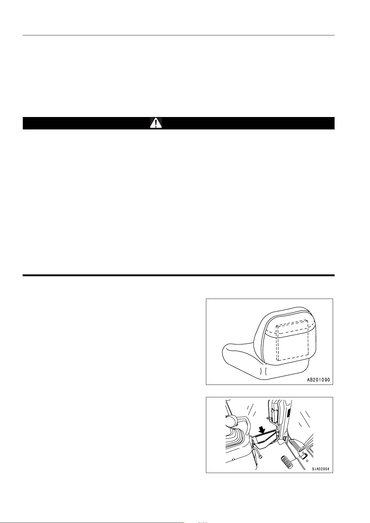
Storage location for the Operation and Maintenance
Manual:
If machine is equipped without cab.
Pocket at rear of operator's seat
If machine is equipped with a cab.
Pocket at rear of operator's seat
Inside of right and left doors
1-2
Page 5

FOREWORD SAFETY INFORMATION
SAFETY INFORMATION 1
To enable you to use this machine safely, safety precautions and labels are given in this manual and affixed to the
machine to give explanations of situations involving potential hazards and of the methods of avoiding such situations.
Signal words
The following signal words are used to inform you that there is a potential hazardous situation that may lead to personal injury or damage.
In this manual and on machine labels, the following signal words are used to express the potential level of hazard.
DANGER
WARNING
CAUTION
Example of safety message using signal word
Indicates an imminently hazardous situation which, if not avoided, will result in death
or serious injury.
Indicates a potentially hazardous situation which, if not avoided, could result in d eath
or serious injury.
Indicates a potentially hazardous situation which, if not avoided, may result in minor or
moderate injury. This word is used also to alert against unsafe practices that may
cause property damage.
WARNING
When standing up from the operator's seat, always place the safety lock lever in the LOCK position.
If you accidentally touch the control levers when they are n ot locked, this may ca use a serious inju ry or
death.
Other signal words
In addition to the above, the following signal words are used to indicate precaution s that shou ld be followed to protect the machine or to give information that is useful to know.
NOTICE
REMARK
This word is used for precautions that must be taken to avoid actions which could shorten
the life of the machine.
This gives information that is useful to know.
1-3
Page 6
SAFETY INFORMATION FOREWORD
q Safety labels
Safety labels are affixed to the machine to inform the operator or maintenance worker on the spot when carrying
out operation or maintenance of the machine that may involve hazard.
This machine uses “Safety labels using words“ and “Safety labels using pictograms“ to indicate safety pr ocedur es.
Example of safety label using words
Safety labels using pictogram
Part No.
Safety pictograms use a picture to expre ss a level of hazardous condition equivalent to the signal word. These safety pictograms use pictures in order to let the operator or
maintenance worker understand the level and type of hazardous condition at all times.
Safety pictograms show the type of hazardous condition at the
top or left side, and the method of avoiding the hazardous condition at the bottom or right side. In addition, the type of hazardous condition is displayed inside a triangle and the method
of avoiding the hazardous condition is shown inside a circle.
Part No
Komatsu cannot predict every circumstance that might involve a potential hazard in operation and maintena nce.
Therefore, the safety messages in this manual and on the machine may not include all po ssible safety precautions.
If any procedures or actions not specifically recommended or allowed in this manual are used, it is your responsibility to take the necessary steps to ensure safety.
In no event should you engage in prohibited uses or actions described in this manual.
The explanations, values, and illustrations in this manual were prepared based on the latest information available
at that time. Continuing improvements in the design of this machine can lead to changes in detail which may not
be reflected in this manual. Consult Komatsu or your Komatsu distributor for the latest available information of
your machine or for questions regarding information in this manual.
The numbers in circles in the illustrations correspond to the numbers in ( ) in the text. (For example: 1 -> (1))
1-4
Page 7

FOREWORD SAFETY INFORMATION
Noise emission levels (D37EX, D37PX)
Two labels ind icating the machine noise level a re affixed on the
machine.
q Sound pressure level at the operator’s station, measured
according to ISO6396 (Dynamic test method, simulated
working cycle).
q Sound power level emitted by the machine, measured
according to ISO 6395 (Dynamic test method, simulated
working cycle). This is the guaranteed value as specified
in European directive 2000/14/EC.
Vibration levels (D37EX, D37PX)
When used for its intended purpose, levels of vibratio n for the
earth-moving machine transmitted from the operator’s seat are
lower than or equal to the tested vibrations for the relative
machinery class in compliance with ISO 7096.
The actual acceleration value for the hands and arms is less
than or equal to 2.5 m/s². The actual acceleration value for the
body is less than or equal to 0.5 m/s².
These values were determined using a representative machine
and measured during the typical operating condition indicated
below according to the measurement procedures that are
defined in the standards ISO 2631/1 and ISO 5349.
1-5
Page 8

SAFETY INFORMATION FOREWORD
Operating condition:
(WHEEL LOADER:) V-shape loading
( H Y DR A U LI C E XC AVAT O RS:) E x cav a t in g ( Dig g i ng- l oading-
rotating-unloading-rotating)
(TRACTOR DOZER:) Dozing and spreading material through
forward/reversing motion
(Rigid/Articulate dumper:) Work cycle (including waiting, travel-
ling, loading, travelling with load, unloading, and travelling without load)
Guide to Reduce Vibration Levels on Machine
The following guides can help an operator of this machine to
reduce the whole body vibration levels:
1. Use the correct equipment and attachments.
2. Maintain the machine according to this manual
q Tire pressures (for wheeled machines), tension of
crawler (for crawler machines)
q Brake and steering systems
q Controls, hydraulic system and linkages
3. Keep the terrain where the machine is working and traveling in good condition
q Remove any large rocks or obstacles
q Fill any ditches and holes
q Site manager should provide machine operators with
machine and schedule time to maintain terrain conditions
4. Use a seat that meets ISO 7096 and keep the seat maintained and adjusted
q Adjust the seat and suspension for the weight and size
of the operator
q Wear seat belt
q Inspect and maintain the seat suspension and adjust-
ment mechanisms
5. Steer, brake, accelerate, shift gears (for wheeled
machines), and move the attachment levers and pedals
slowly so that the machine moves smoothly
1-6
Page 9

FOREWORD SAFETY INFORMATION
6. Adjust the machine speed and travel path to minimize the
vibration level
q When pushing with bucket or blade, avoid sudden
loading; load gradually
q Drive around obstacles and rough terrain conditions
q Slow down when it is necessary to go over roug h ter-
rain
q Make the curve radius of traveling path as large as
possible
q Travel at low speed when traveling around sharp
curves
7. Minimize vibrations for long work cycle or long distance
traveling
q Reduce speed to prevent bounce
q Transport machines long distances between worksites
8. The following guidelines can be effective to m inimize risks
of low back pain
q Operate the machine only when you are in good
health.
q Provide breaks to reduce long periods of sitting in the
same posture
q Do not jump down from the cab or machine
q Do not repeatedly handle and lift loads
1-7
Page 10
INTRODUCTION FOREWORD
INTRODUCTION 1
This Komatsu machine is designed to be used mainly for the following work:
q Dozing
q Smoothing
q Cutting into hard or frozen ground or ditching
See the section “WORK POSSIBLE USING BULLDOZER (3-95)“ for further details.
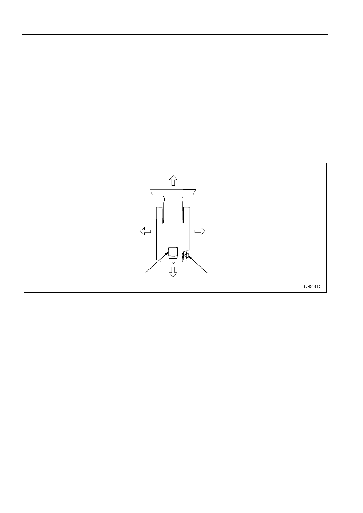
FRONT/REAR, LEFT/RIGHT DIRECTIONS OF MACHINE 1
Front
Left
Operator’s seat
Rear
In this manual, the terms front, rear, left, and right refer to the travel direction as seen from the operator's seat
when the operator's seat is facing the front and the sprocket is at the rear of the machine.
Right
Sprocket
1-8
Page 11
FOREWORD NECESSARY INFORMATION
NECESSARY INFORMATION 1
When requesting service or ordering replacement parts, please inform your Komatsu distributor of the following
items.
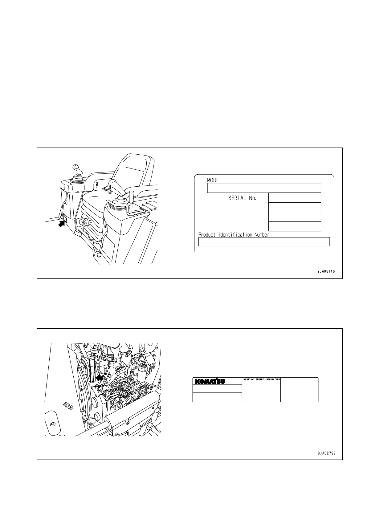
PRODUCT IDENTIFICATION NUMBER (PIN)/MACHINE SERIAL NO. PLATE 1
This is at the front bottom right of the oper ator's seat.
The design of the nameplate differs according to the territory.
ENGINE SERIAL NO. PLATE 1
This is at the front top of the engine on the left side machine.
EPA: Environmental Protection Agency, U.S.A.
1-9
Page 12

NECESSARY INFORMATION FOREWORD
POSITION OF SERVICE METER 1
The service meter is provided at the lower part of the monitor
panel.
TABLE OF ENTER SERIAL NO. AND DISTRIBUTORN 1
Machine serial No.
Engine serial No.
Product Identification Number
Manufacturers name:
Address:
Distributor
Address
Phone
Service personnel for your
machine:
KOMATSU LTD.
3-6 Akasaka
Minato-ku, 101 Tokyo
Japan
1-10
Page 13

FOREWORD NECESSARY INFORMATION
MACHINE SERIAL PLATE.
Model
Seriel Number
Manufacturing year
Weight
Engine power
Product Identification Number
Manufacturer
kg
kW
1-11
Page 14

CONTENTS
CONTENTS
FOREWORD
FOREWORD.........................................................................................................................................................1-2
SAFETY INFORMATION......................................................................................................................................1-3
Noise emission levels (D37EX, D37PX) .....................................................................................................1-5
Vibration levels (D37EX, D37PX) ...............................................................................................................1-5
GUIDE TO REDUCE VIBRATION LEVELS ON MACHINE ..............................................................1-6
INTRODUCTION................................................................................................................................................... 1-8
FRONT/REAR, LEFT/RIGHT DIRECTIONS OF MACHINE.......................................................................1-8
NECESSARY INFORMATION .............................................................................................................................1-9
PRODUCT IDENTIFICATION NUMBER (PIN)/MACHINE SERIAL NO. PLATE........................................ 1-9
ENGINE SERIAL NO. PLATE.....................................................................................................................1-9
POSITION OF SERVICE METER ............................................................................................................ 1-10
TABLE OF ENTER SERIAL NO. AND DISTRIBUTORN..........................................................................1-10
MACHINE SERIAL PLATE. ...................................................................................................................... 1-11
SAFETY
SAFETY................................................................................................................................................................2-2
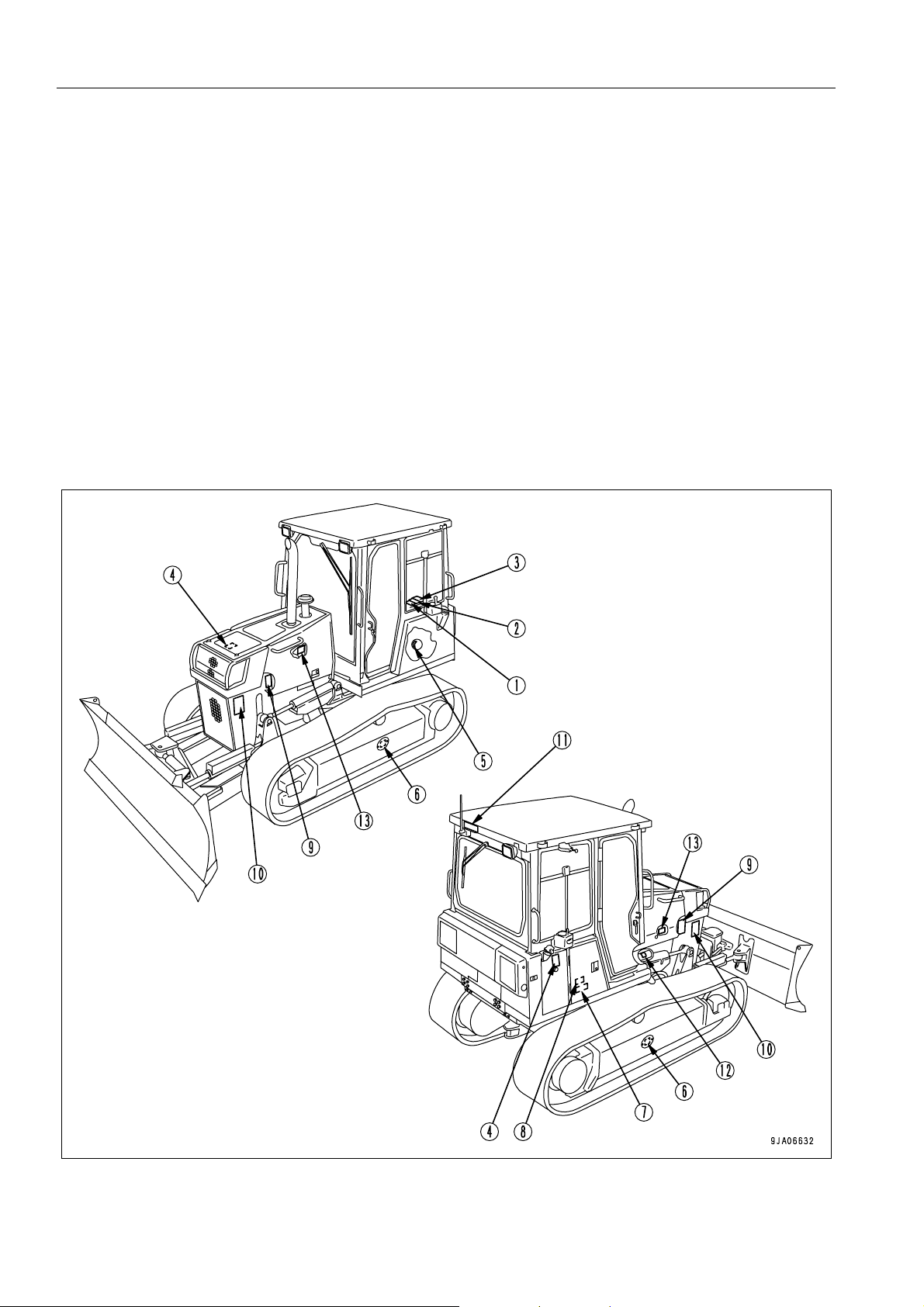
SAFETY LABELS.................................................................................................................................................2-4
POSITIONS OF SAFETY PICTOGRAMS ..................................................................................................2-4
SAFETY LABELS ........ ... ... .... ... ... ... .... ...................................... .... ...................................... ........................2-5
GENERAL PRECAUTIONS ...............................................................................................................................2-10
PRECAUTIONS FOR OPERATION...................................................................................................................2-19
STARTING ENGINE................................................................................................................................. 2-19
OPERATION.............................................................................................................................................2-21
TRANSPORTATION................................................................................................................................. 2-24
BATTERY ................................................................................................................................................. 2-25
TOWING ...................................................................................................................................................2-27
PRECAUTIONS FOR MAINTENANCE.............................................................................................................. 2-28
1-12
Page 15

CONTENTS
OPERATION
GENERAL VIEW .................................................................................................................................................. 3-2
GENERAL VIEW OF MACHINE..................................... ... .... ... ... ... .... ... ... ....................................... ........... 3-2
GENERAL VIEW OF CONTROLS AND GAUGES..................................................................................... 3-3
EXPLANATION OF COMPONENTS.................................................................................................................... 3-5
FRONT PANEL........................................................................................................................................... 3-5
CHECK MONITOR SYSTEM ............................................................................................................3-6
EMERGENCY CAUTION ITEMS ...................................................................................................... 3-7
CAUTION CAUTION ITEMS .............................................................................................................3-9
METER GROUP.... ... ... ... .... ... ... ....................................... ... ... .... ...................................... ... ............. 3-11
LAMPS............................................................................................................................................. 3-20
METHOD OF USING MAINTENANCE MODE................................................................................ 3-21
SWITCHES............................................................................................................................................... 3-30
CONTROL LEVERS AND PEDALS ......................................................................................................... 3-35
FUSE ........................................................................................................................................................ 3-41
ELECTRIC POWER TAKE-OUT ADAPTER ............................................................................................ 3-42
DOOR - OPEN LOCK............................................................................................................................... 3-43
SASH GLASS INTERMEDIATE LOCK..................................................................................................... 3-43
CAP, COVER WITH LOCK....................................................................................................................... 3-44
METHOD OF OPENING AND CLOSING CAP WITH LOCK ............................. .... ... ... ... ... .... ... ... ... 3-44
METHOD OF OPENING AND CLOSING COVER WITH LOCK..................................................... 3-45
DOOR POCKET ....................................................................................................................................... 3-45
ASHTRAY................................................................................................................................................. 3-46
LUNCHBOX HOLDER BELT.................................................................................................................... 3-46
CUP HOLDER .......................................................................................................................................... 3-46
TOOL BOX................................................................................................................................................ 3-47
GREASE PUMP HOLDER........................................................................................................................ 3-47
CAR STEREO, HANDLING...................................................................................................................... 3-48
EXPLANATION OF COMPONENTS............................................................................................... 3-48
METOD OF OPERATION................................................................................................................ 3-53
PRECAUTION WHEN USING......................... ... ... ... .... ...................................... .... ... ... ... ... .... ... ... ... 3-55
AIR CONDITIONER, HANDLING ............................................................................................................. 3-56
EXPLANATION OF PARTS............................................................................................................. 3-56
PREVENTION METHOD OF ENTRY OF DUST............................................................................. 3-58
PRECAUTION WHEN USING AIR CONDITIONER........................................................................ 3-58
INSPECTION DURING OFF-SEASON........................................................................................... 3-58
PROCEDURE FOR REPLACING RECEIVER................................................................................ 3-59
CLEANING AIR FILTER.................................................................................................................. 3-59
ACCUMULATOR, HANDLING.................................................................................................................. 3-60
METHOD OF RELEASING PRESSURE IN OPERATING CIRCUIT ON MACHINE EQUIPPED WITH
ACCUMULATOR............................................................................................................................. 3-60
OPERATION....................................................................................................................................................... 3-61
CHECK BEFORE STARTING ENGINE, ADJUST.................................................................................... 3-61
WALK-AROUND CHECK ................................................................................................................ 3-61
CHECK BEFORE STARTING............................................ ... .... ... ... ... ... .... ... ... ... .... ......................... 3-63
1-13
Page 16

CONTENTS
ADJUSTMENT.................................................................................................................................3-72
OPERATION AND CHECK BEFORE STARTING ENGINE............................................................3-75
STARTING ENGINE................................................................................................................................. 3-77
NORMAL STARTING ...................................... ... .... ... ... ... .... ... ... ....................................... ... ... ......... 3-77
STARTING IN COLD WEATHER....................................................................................................3-79
OPERATIONS AND CHECKS AFTER STARTING ENGINE................................................................... 3-81
BREAKING IN THE NEW MACHINE ..............................................................................................3-81
WARMING UP OPERATIONS ............... ...................................... .... ... ... ... ... .... ... ... ... .... ... ...............3-81
STARTING IN COLD WEATHER....................................................................................................3-82
STOPPING ENGINE . ... ... ... ....................................... ... .... ... ....................................... ... ... ... .... ..................3-84
MACHINE OPERATION ........................................................................................................................... 3-85
MOVING MACHINE................................................................... ... ....................................... ... ......... 3-85
STOPPING MACHINE..................................................................................................................... 3-88
SHIFTING GEARS....................................................................................................................................3-89
SHIFTING BETWEEN FORWARD AND REVERSE ................................................................................3-90
STEERING MACHINE.............................................................................................................................. 3-91
NORMAL TURNING............................................... ... ....................................... ... ... .........................3-91
TURNING WHILE DESCENDING A SLOPE............................. ... .... ... .......................................... .. 3-92
PRECAUTIONS FOR OPERATION ......................................................................................................... 3-93
PAY ATTENTION TO GAUGES......................................................................................................3-93
PERMISSIBLE WATER DEPTH...................................................................................................... 3-93
METHOD OF USING BRAKES .......................................................................................................3-93
PRECAUTIONS WHEN TRAVELING UP OR DOWN HILLS..........................................................3-93
PRECAUTIONS ON SLOPES.........................................................................................................3-94
IT IS PROHIBITED TO KEEP THE DOOR OPEN DURING OPERATIONS................................... 3-94
IT IS PROHIBITED TO MODIFY THE CAB GLASS IN ANY WAY THAT WILL
OBSTRUCT THE VIEW.................................................................................................................. 3-94
PRECAUTIONS FOR BLIND SPOTS CAUSED BY CAB STAY..................................................... 3-94
WORK POSSIBLE USING BULLDOZER .................................................................................................3-95
DOZING........................................................................................................................................... 3-95
SMOOTHING...................................................................................................................................3-95
CUTTING INTO HARD OR FROZEN GROUND OR DITCHING.................................................... 3-96
FELLING TREES, REMOVING STUMPS ....................................................................................... 3-96
SIDE-CUTTING OPERATIONS....................................................................................................... 3-96
PARKING MACHINE ....................................... ... ....................................... ... ............................................ 3-97
CHECK AFTER FINISHING WORK ...................................... ... .... ... ... ... .... ... ... ... ... ................................... 3-98
BEFORE STARTING ENGINE........................................................................................................ 3-98
AFTER STARTING ENGINE...........................................................................................................3-98
LOCKING..................................................................................................................................................3-99
TIPS FOR LONGER UNDERCARRIAGE LIFE ...................................................................................... 3-100
OPERATION METHOD.................................................................................................................3-100
INSPECTION AND ADJUSTMENT...............................................................................................3-100
INSPECTION AND REPAIR.......................................................................................................... 3-101
TRANSPORTATION......................................................................................................................................... 3-103
TRANSPORTATION MEANS.................................................................................................................3-103
PRECAUTIONS WHEN REMOVING WORK EQUIPMENT................................................................... 3-103
REMOVING CAB................... ... ... ... .... ... ... ....................................... ... ... .... ............................................. 3-103
1-14
Page 17

CONTENTS
LOADING, UNLOADING WORK.... ... ....................................... ... ... .... ... ... ... ... .... ... ... ... ........................... 3-104
LIFTING MACHINE................................................................................................................................. 3-108
COLD WEATHER OPERATION...................................................................................................................... 3-109
PRECAUTIONS FOR LOW TEMPERATURE............................. ... .... ... ... ... ... .... ... ... ... .... ... ... ................. 3-109
AFTER COMPLETION OF WORK......................................................................................................... 3-111
AFTER COLD WEATHER...................................................................................................................... 3-111
LONG-TERM STORAGE..................................................................................................................................3-112
BEFORE STORAGE............................................................................................................................... 3-112
DURING STORAGE............................................................................................................................... 3-112
AFTER STORAGE.................................................................................................................................. 3-112
TROUBLESHOOTING...................................................................................................................................... 3-113
AFTER RUNNING OUT OF FUEL.......................................................................................................... 3-113
MACHINE TOWING METHOD............................. .... ... ... ... ....................................... ... .... ... .................... 3-113
WHEN IT IS POSSIBLE TO START ENGINE.............................. ... ... ... .... ... ... ... .... ... ... ... ... .... ... ... . 3-114
WHEN ENGINE DOES NOT START ................................. ... .... ... ... ... ... ........................................ 3-115
IF BATTERY IS DISCHARGED.............................................................................................................. 3-120
REMOVE AND INSTALL BATTERY ............................... ... ... .... ... ... ... ... .... ... ... ... .... ... ... ... ... ........... 3-121
PRECAUTIONS FOR BATTERY CHARGING .............................................................................. 3-121
STARTING ENGINE WITH BOOSTER CABLE ............................................................................ 3-122
WHEN ENGINE DOES NOT STOP........................................................................................................ 3-124
OTHER TROUBLE ................................................................................................................................. 3-125
ELECTRICAL SYSTEM................................................................................................................. 3-125
MONITOR PANEL......................................................................................................................... 3-126
CHASSIS....................................................................................................................................... 3-127
ENGINE......................................................................................................................................... 3-128
MAINTENANCE
GUIDE TO MAINTENANCE................................................................................................................................. 4-2
OUTLINE OF SERVICE........................................................................................................................................ 4-5
OUTLINE OF OIL, FUEL, COOLANT, AND PERFORMING OIL CLINIC .................................................. 4-5
OIL..................................................................................................................................................... 4-5
FUEL.................................................................................................................................................. 4-5
COOLANT ......................................................................................................................................... 4-6
GREASE............................................................................................................................................ 4-6
CARRYING OUT KOWA (KOMATSU OIL WEAR ANALYSIS)......................................................... 4-6
STORING OIL AND FUEL................................................................................................................. 4-7
FILTERS............................................................................................................................................ 4-7
RELATING TO ELECTRIC SYSTEM ......................................................................................................... 4-8
WEAR PARTS LIST............................................................................................................................................. 4-9
WEAR PARTS LIST.................................................................................................................................... 4-9
USE OF FUEL, COOLANT AND LUBRICANTS ACCORDING TO AMBIENT TEMPERATURE .................... 4-11
1-15
Page 18

CONTENTS
PROPER SELECTION OF FUEL, COOLANT AND LUBRICANTS .........................................................4-11
STANDARD TIGHTENING TORQUES FOR BOLTS AND NUTS.....................................................................4-15
TORQUE LIST.......................................................................................................................................... 4-15
PERIODIC REPLACEMENT OF SAFETY CRITICAL PARTS ..........................................................................4-16
SAFETY CRITICAL PARTS................................... ... ... ....................................... ... .... ... ... ... .... ... ...............4-16
MAINTENANCE SCHEDULE CHART ...............................................................................................................4-17
MAINTENANCE SCHEDULE CHART......................................................................................................4-17
WHEN REQUIRED.......................................................................................................................... 4-17
CHECK BEFORE STARTING ......................................................................................................... 4-17
EVERY 50 HOURS SERVICE................... ......................................................................................4-17
EVERY 250 HOURS SERVICE....................................................................................................... 4-17
EVERY 500 HOURS SERVICE....................................................................................................... 4-17
EVERY 1000 HOURS SERVICE.....................................................................................................4-17
EVERY 2000 HOURS SERVICE.....................................................................................................4-18
EVERY 4000 HOURS SERVICE.....................................................................................................4-18
SERVICE PROCEDURE .................................................................................................................................... 4-19
WHEN REQUIRED................ ... ....................................... ... ... ... ....................................... ... .... ..................4-19
CHECK, CLEAN AND REPLACE AIR CLEANER ELEMENT......................................................... 4-19
CLEAN INSIDE OF COOLING SYSTEM ........................................................................................ 4-23
CHECK TRACK SHOE TENSION, ADJUST...................................................................................4-25
CHECK AND TIGHTEN TRACK SHOE BOLTS..............................................................................4-27
CHECK ELECTRICAL INTAKE AIR HEATER ................................................................................ 4-27
REVERSE AND REPLACE END BITS AND CUTTING EDGES..................................................... 4-28
CHECK IDLER OIL LEVEL, ADD OIL ............................................................................................. 4-29
ADJUST IDLER CLEARANCE ............................................... ... ... .... ... ...................................... .... .. 4-29
ADJUST PLAY IN CENTER BALL ..................................................................................................4-30
GREASE DOOR HINGE..................................................................................................................4-30
CHECK DOOR LOCK STRIKER..................................................................................................... 4-31
CHECK, ADJUST AIR CONDITIONER ........................................................................................... 4-31
CHECK WINDOW WASHER FLUID LEVEL, ADD FLUID.............................................................. 4-33
REPLACE WIPER BLADE ........................ ... ....................................... ... ... ... .... ... ... ... .... ... ... ... .........4-33
PROCEDURE FOR BLEEDING AIR IN HYDRAULIC SYSTEM.....................................................4-34
PROCEDURE FOR RELEASING INTERNAL PRESSURE OF HYDRAULIC SYSTEM................. 4-35
CHECK BEFORE STARTING ............... ... ... .... ... ... ... ... .... ... ... ... ....................................... ... .... ... ... ... ......... 4-36
EVERY 50 HOURS SERVICE..................................................................................................................4-37
DRAIN WATER, SEDIMENT FROM FUEL TANK...........................................................................4-37
EVERY 250 HOURS SERVICE................................................................................................................ 4-38
LUBRICATING.................................................................................................................................4-38
CHECK OIL LEVEL IN FINAL DRIVE CASE, ADD OIL ..................................................................4-40
CHECK LEVEL OF BATTERY ELECTROLYTE ............................................................................. 4-41
CHECK BRAKE PERFORMANCE..................................................................................................4-43
CLEAN AIR CONDITIONER AIR FILTER (FRESH/RECIRC FILTER)............................................4-44
EVERY 500 HOURS SERVICE................................................................................................................ 4-45
REPLACE FUEL FILTER CARTRIDGE ....................................... .... ... ... ... ... .... ... ... ... .... ..................4-45
CHANGE OIL IN ENGINE OIL PAN, REPLACE ENGINE OIL FILTER CARTRIDGE....................4-48
1-16
Page 19

CONTENTS
REPLACE CORROSION RESISTOR CARTRIDGE ....................................................................... 4-49
CLEAN, CHECK RADIATOR FINS AND OIL COOLER FINS......................................................... 4-50
EVERY 1000 HOURS SERVICE.............................................................................................................. 4-51
CHANGE OIL IN FINAL DRIVE CASE............................................................................................ 4-51
CHECK FAN BELT TENSION, ADJUST......................................................................................... 4-51
CHECK ALL TIGHTENING PARTS OF TURBOCHARGER........................................................... 4-51
CHECK PLAY OF TURBOCHARGER ROTOR ................. ... .... ... ... ... ... .... ... ... ... .... ......................... 4-52
CHECK FOR LOOSE ROPS MOUNT BOLTS................................................................................ 4-52
EVERY 2000 HOURS SERVICE.............................................................................................................. 4-53
CHANGE OIL IN HYDRAULIC TANK, REPLACE OIL FILTER CARTRIDGE AND CLEAN SUCTION
STRAINER....................................................................................................................................... 4-53
CLEAN, CHECK TURBOCHARGER............................................................................................... 4-55
CHECK VIBRATION DAMPER ................................ .... ...................................... .... ... ... ... ... .... ... ... ... 4-55
CHECK ALTERNATOR, STARTING MOTOR .......................... ......................................... .... ... ... ... 4-55
CHECK ENGINE VALVE CLEARANCE, ADJUST.......................... ... ... .... ... ... ... .... ... ... ... ... .... ... ... ... 4-55
EVERY 4000 HOURS SERVICE.............................................................................................................. 4-56
CHECK WATER PUMP................................... ... ....................................... ... ... ... .... ... ... ... ... .... ... ...... 4-56
SPECIFICATIONS
SPECIFICATIONS................................................................................................................................................ 5-2
ATTACHMENTS, OPTIONS
GENERAL PRECAUTIONS ................................................................................................................................. 6-2
PRECAUTIONS RELATED TO SAFETY ...................................................................................................6-2
HANDLING HYDRAULIC RIPPER....................................................................................................................... 6-3
GENERAL VIEW............................................................. ... .... ... ... ....................................... ........................ 6-3
EXPLANATION OF COMPONENTS.......................................................................................................... 6-4
OPERATION............................................................................................................................................... 6-5
CHECK BEFORE STARTING ENGINE, ADJUST ............................. ... .... ... ... ... .... ... ... ... ... .... ... ... ... .. 6-5
PRECAUTIONS WHEN OPERATING............................................................................................... 6-5
ADUSTING POSTURE OF WORK EQUIPMENT ............................................................................. 6-5
TROUBLESHOOTING................................................................................................................................ 6-6
OTHER TROUBLE...................................... .... ...................................... .... ........................................ 6-6
MAINTENANCE.......................................................................................................................................... 6-6
EVERY 250 HOURS SERVICE.........................................................................................................6-6
DELUXE SEAT..................................................................................................................................................... 6-7
HEADREST .......................................................................................................................................................... 6-9
EQUIPPING FIRE EXTINGUISHER AND FIRST-AID KIT................................................................................. 6-10
1-17
Page 20

CONTENTS
INDEX
COLOPHON
1-18
Page 21

SAFETY
12
WARNING
Please be sure that you fully underst an d this manual an d the
precautions discribed in this manual and the safety labels
on the machine. When operating or servicing the machine,
always follow these precaustions strictly.
Page 22

SAFETY SAFETY
SAFETY 2
SAFETY LABELS................................................................................................................................................ 2-42
POSITION OF SAFETY PICTOGRAMS......................................................................................................2-42
SAFETY LABELS.........................................................................................................................................2-52
GENERAL PRECAUTIONS
Safety rules................................................................................................................................................2-102
If abnormalities are found................................ .... ... ... ... ... .... ... ... ... .... ... .......................................................2-102
Clothing and personal protective items......................................................................................................2-102
Fire extinguisher and first aid kit ................................................................................................................2-102
Safety features...........................................................................................................................................2-112
Keep machine clean................................................................................................................................... 2-112
Inside operator's compertment................................................................................................................... 2-112
Always apply lock when leaving operator's seat........................................................................................ 2-112
Handrails and steps ...................................................................................... ... ... ... ... .... ... ..........................2-122
Mounting and dismounting......................................................................................................................... 2-132
No people on attachment........................................................................................................................... 2-132
Crushing or cutting prevention...................................................................................................................2-132
Prevention of burns....................................................................................................................................2-132
Fire prevention...........................................................................................................................................2-142
Action if fire occurs.....................................................................................................................................2-152
Window washer liquid ................................................................................................................................2-152
Precautions when using ROPS (Roll Over Protective Structure).................................. ... ... ... .... ... ... ... ... .... 2-152
Precautions for attachments ........................................... .... ... ... ... .... ..........................................................2-152
Unauthorized medification..........................................................................................................................2-152
Safety at worksite....................................................................................................................................... 2-162
Working on loose ground........................................................................................................................... 2-162
Do not go close to high-voltage cables ......................................................................................................2-162
Ensure good visibility .................................................................................................................................2-172
Ventilation for enclosed aresa.................................................................................................................... 2-172
Checking signalman's signals and signs.................................................................................................... 2-172
Emergency exit from operator's cab ..........................................................................................................2-172
Be careful about asbestos dust..................................................................................................................2-182
PRECAUTIONS FOR OPERATIONS............................................................................................................... 2-192
STARTING ENGINE..................................................................................................................................2-192
Checks before starting engine ............................................................................................................2-192
Precautions when starting.................. ... ... .... ... ... ... ... .... ... ... ... .... ... .......................................................2-192
Precautions in cold areas.................................................................................................................... 2-202
OPERATION.............................................................................................................................................. 2-212
Checks before operation.....................................................................................................................2-212
Precautions for moving machine forward or in reverse.......................................................................2-212
Precautions when traveling...................... .... ... ... ... ... .... ... ... ... ....................................... ... ....................2-212
Traveling on slopes............................................................................................................................. 2-222
Using brakes............................... .... ... ....................................... ... .......................................................2-222
Operate carefully on snow ..................................................................................................................2-232
Parking machine...... ... ... .... ... ... ... .... ... ... ....................................... ... ... .... ... ... ... .................................... 2-232
TRANSPORTATION..................................................................................................................................2-242
Loading and unloading........................................................................................................................2-242
Shipping.............................................................................................................................................. 2-242
BATTERY...................................................................................................................................................2-252
Battery hazard prevention..................... ... .... ... ... ... ... .... ...................................... .... ... ... ... ....................2-252
Starting with booster cable.................................................................................................................. 2-262
TOWING .................................................................................................................................................... 2-272
When towing ....................................................................................................................................... 2-272
2-2
Page 23

SAFETY SAFETY
PRECAUTIONS FOR MAINTENANCE ............................................................................................................2-282
Warning tag................................................................................................................................................ 2-282
Keep work place clean and tidy............... .... ... ... ... ... .... ... ... ... .... ... ... ... .... ... ... ... ... .... ... ... ... .... ... .................... 2-282
Appoint leader when working with others .................................................................................................. 2-282
Stop engine before carrying out inspection and maintenance................................................................... 2-282
Two workers for maintenance when engine is running.............................................................................. 2-292
Proper tools........................ ...................................... .... ... ... ... ..................................................................... 2-302
No unauthorized personnel into area......................................................................................................... 2-302
Attachments............................................................................................................................................... 2-302
Work under the machine.................................... ....................................... ... ... ... .... ... ... ... .... ....................... 2-312
Noise.......................................................................................................................................................... 2-312
Precautions when using hammer............................................................................................................... 2-312
Repair welding........................................................................................................................................... 2-312
Removing battery terminal.... ... ... .... .......................................... .......................................... ....................... 2-312
Precautions when Using high-pressure grease to adjust track tension ..................................................... 2-322
Do not disassemble recoil spring............................................................................................................... 2-322
Precaution with high-pressure oil............................................................................................................... 2-322
Handling high-pressure hoses ................................................................................................................... 2-332
Waste material........................................................................................................................................... 2-332
Maintenance for air conditioner.................................................................................................................. 2-332
Compressed air.......................................................................................................................................... 2-332
Periodic replacement of safety critical parts .............................................................................................. 2-332
2-3
Page 24
SAFETY LABELS SAFETY
SAFETY LABELS 2
The following warning signes and safety labels are used on this machine.
q Be sure that you fully understand the correct position and content of labels.
q To ensure that the content of labels can be read properly, be sure that they are in the correct place and always
keep them clean. When cleaning them, do not use organic solvents or gasoline. These may cause the labels
to peel off.
q There are also other labels in addition to the warning signes and safety labels. Handle those labels in the
same way.
q If the labels are damaged, lost, or cannot be read properly, replace them with new ones. For details of the p art
numbers for the labels, see this manual or the actual label, and place an order with Komatsu distributor.
POSITIONS OF SAFETY PICTOGRAMS 2
2-4
Page 25
SAFETY SAFETY LABELS
SAFETY LABELS 2
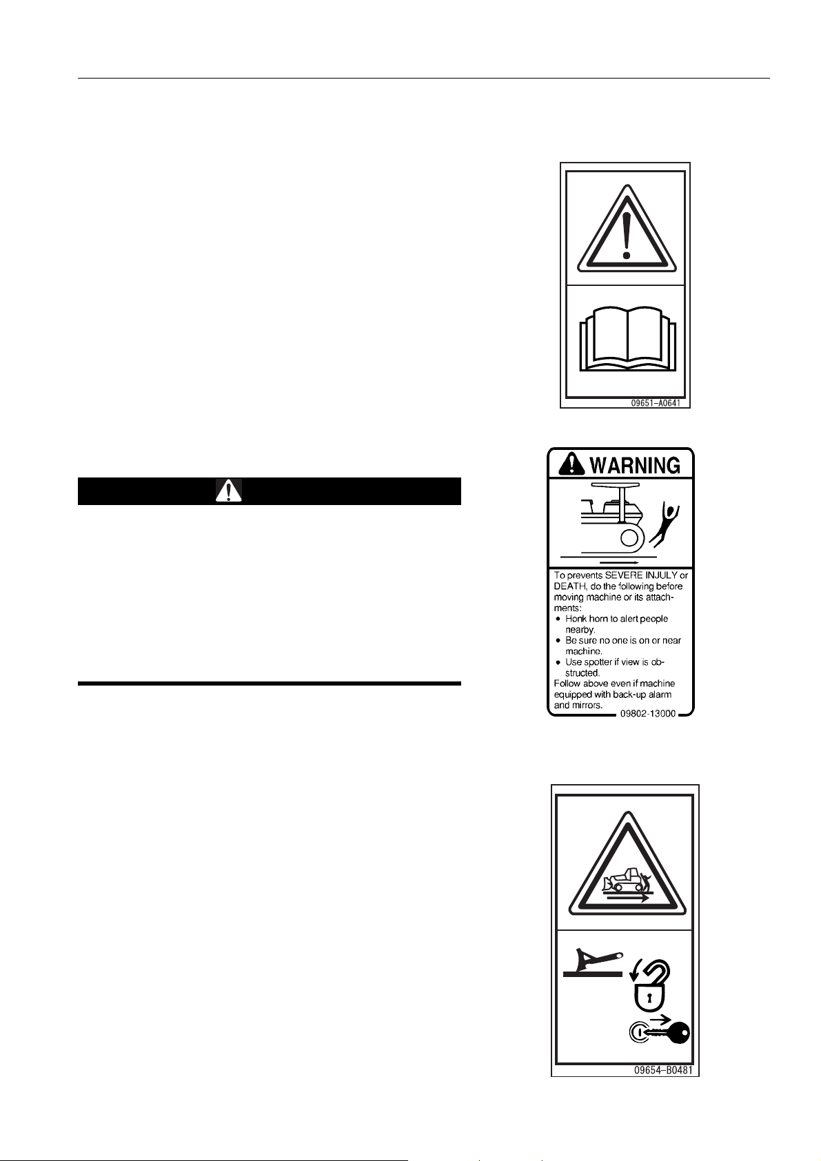
(1) Caution before operating machine (09651-A0481)
q Warning!
q Read manual before operation, maintaince, disassembly,
assembly and transportation.
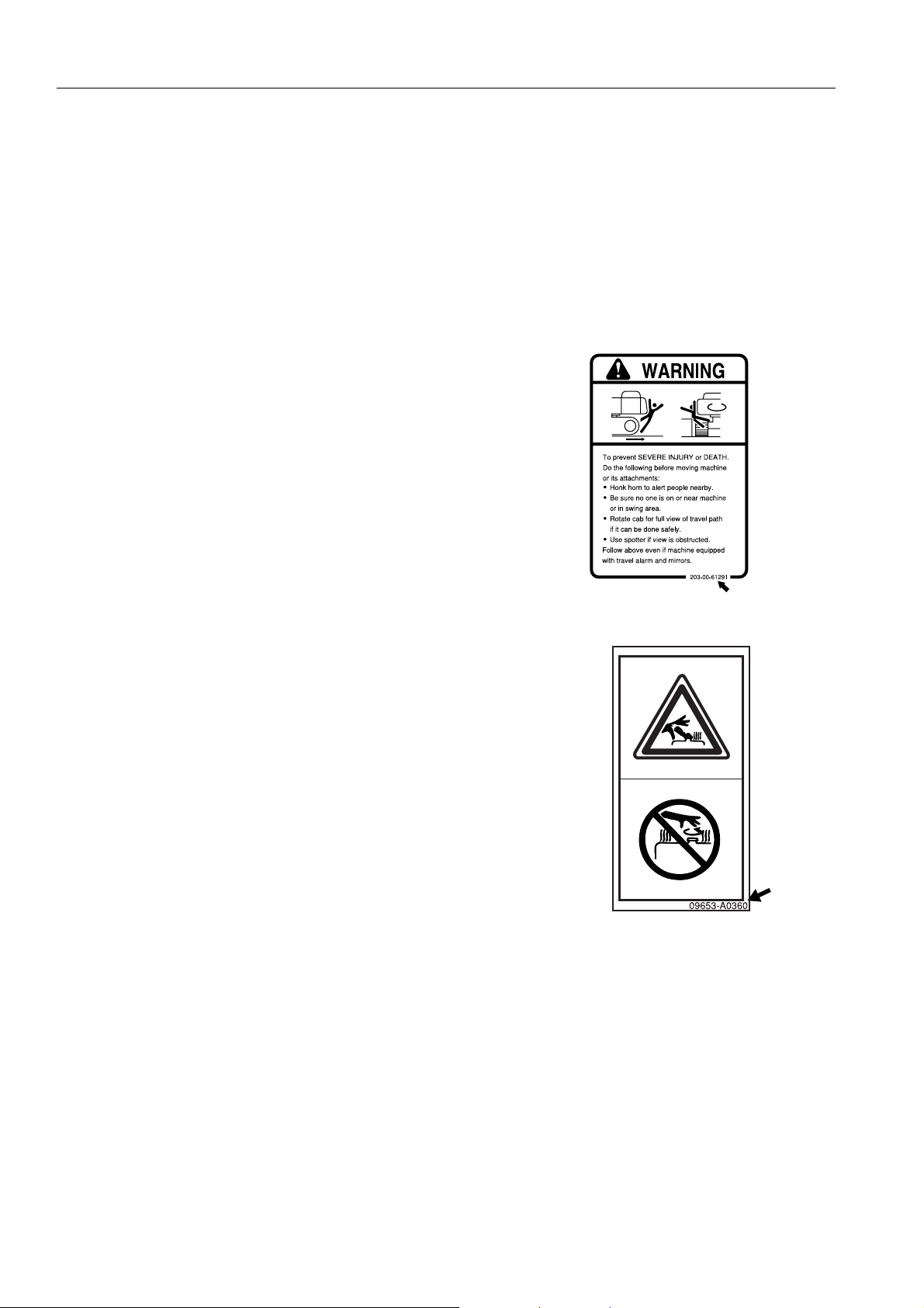
(2) Caution before moving in reverse (09802-13000)
WARNING
To prevents SEVERE INJURY or DEATH, do the following
before moving machine or its attachments:
q Honk horn to alert people nearby.
q Be sure no one is on or near the machine.
q Use spotter if view is obstructed.
Follow above even if the machine is equipped with backup alarm and mirrors.
(3) Caution for leaving operator's seat (09654-B0481)
q Sign indicates a hazard of unexpected m oving of stopped
machine.
q Lower working device to ground, move safety lever to lock
position and take engine key with you before leaving
machine.
2-5
Page 26
SAFETY LABELS SAFETY
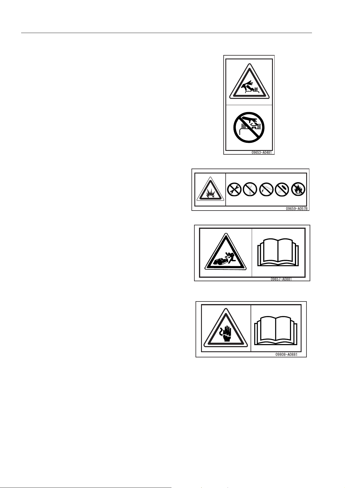
(4) Caution with high-temperature coolant, hydraulic oil
(09653-A0481)
q Never remove the cap when the engine is at operating
(high) temperature. Stream or high temperature oil blowing
up from the radiator or hydraulic tank, will cause personal
injury and or burns.
q Never remove the radiator or hydraulic tank oil filler when
cooling water or hydraulic oil is at high temperatures.
(5) Caution for accumulator (09659-A057B) (If equipped)
q There is the hazard of explotion causing injury.
q Do not disassemble the accumulator, make holes in it, cut
it, hit it roll it or bring it near flame.
(6) Caution for adjusting track tension (09657-A0881)
The safety label is attached to the rear side of the track adjust-
ment window cover.
q Sign indicates a hazard or flining plug from track adjuster
that could cause injury.
q Read the manual and adjusting track for safe and proper
handling.
(7) Caution for battery cable (09808-A0881)
q Sing indicates an electric hazard from handling the cable.
q Read the manual for save and proper hand lin g.
2-6
Page 27
SAFETY SAFETY LABELS
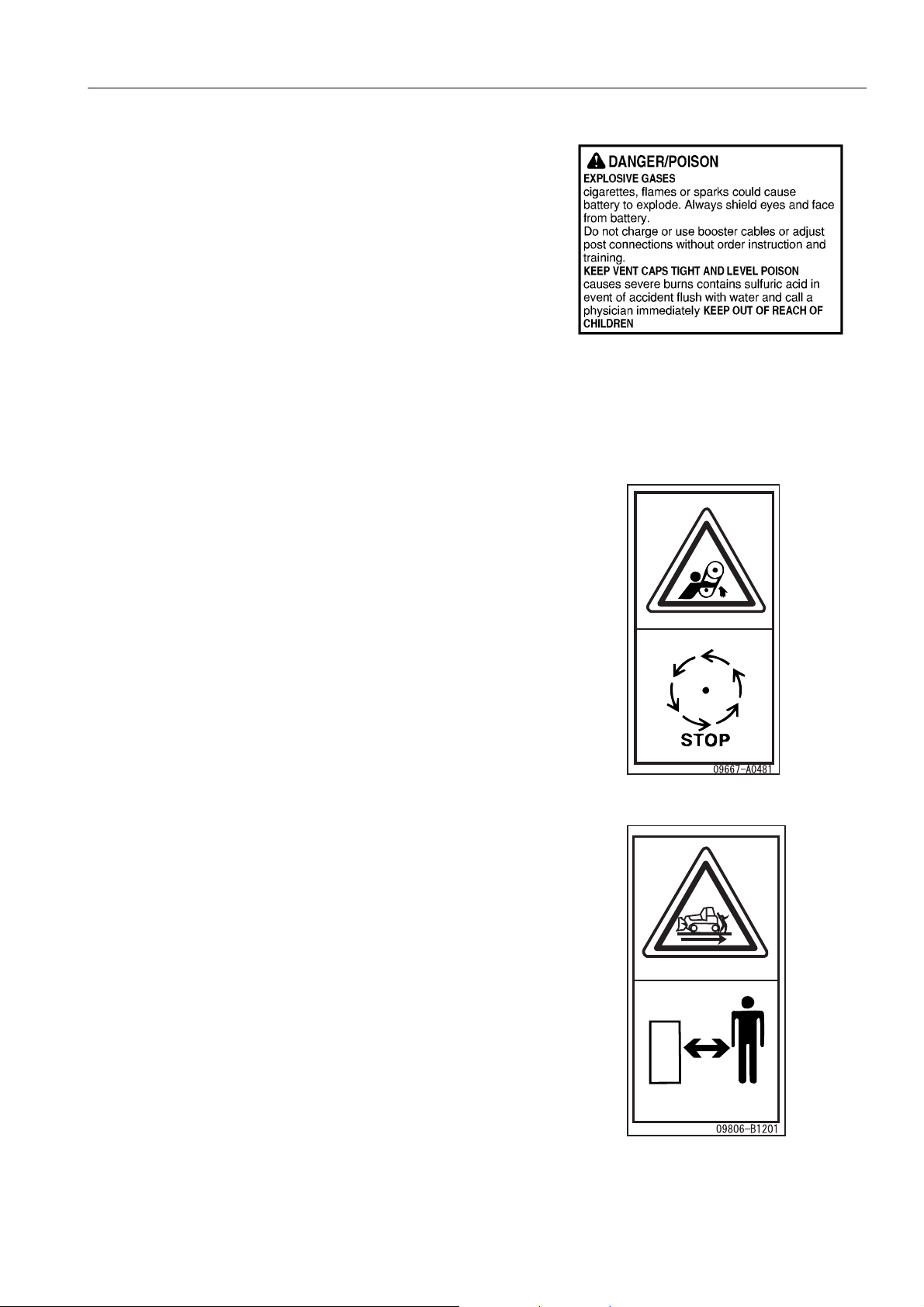
(8) Caution for battery (This plate is stick on the machine by the
battery maker)
DANGER/POISON
EXPLOSIVE GASES
Cigarettes, flames or sparks could cause battery to explode.
Always shield eyes and face from battery.
Do not charge or use booster cables or adjust post connections
without order instruction and training.
KEEP VENT CAPS TIGHT AND LEVEL POISON causes
severe burns contains sulfuric acid in event of accident flush
with water and call a physician immediately.
KEEP OUT OF REACH OF CHILDREN
(9) Caution for engine running (09667-A0481)
q Sign indicates a hazard of rotating parts, such as belt.
q Turn off before inspection and maintenance.
(10) Caution for approach when machine moving
(09806-B1201)
q Sign indicates a hazard of being run over by moving e quip -
ment.
q Keep a safe distance from equipment when it is moving.
2-7
Page 28

SAFETY LABELS SAFETY
(11) Caution for ROPS (09620-A2000)
ROPS/FOBS CERTIFICATION
This protective structure complies with the standard provided
that it is properly equipped on the machine which mass is less
than the specified maximum mass.
MODEL MACHINE MODEL FOPS LEVEL No.
SERIAL No. MAX. MASS (kg)
WARNING
q If some modification is applied to the ROPS or FOPS, it
might not enough strength and might not be complied
with the standard. Consult Komatsu distributor before
altering.
q ROPS or FOBS may provide less protection if it has
been structurally damaged or involved roll-over. Consult Komatsu distributor in that case.
q Always wear seat belt when moving
(12) Prohibition of jump start (09842-A0481)
q Start the engine only after sitting down in the operator’s
seat.
q Do not attempt to start the engine by short-circuiting the
engine starting circuit. Such an act may cause a serious
bodily injury or fire.
2-8
Page 29

SAFETY SAFETY LABELS
(13) Caution with high-temperature parts (09817-A0753)
q Sign indicates a burn hazard from touching heated parts,
such as engine, motor, or muffler during or right after operation.
q Never toch when hot.
2-9
Page 30
GENERAL PRECAUTIONS SAFETY
GENERAL PRECAUTIONS 2
SAFETY RULES
q Only trained and authorized personnel can operate and maintain the machine.
q Follow all safety rules, precautions and instructions when operating or performing maintenance on the
machine.
q If you are under the influence of alcohol or medication, your ability to safely operate or repair your machine
may be severly impaired putting yourself and everyone else on your jobsite in danger.
q When working with another operator or with a person on worksite traffic duty, be sure that all personnel under-
stand all hand signals that are to be used.
IF ABNORMALITIES ARE FOUND
If you find any abnormality in the machine during operation or maintenance (noise, vibration, smell, incorrect
gauges, smoke, oil leakage, etc., or any abnormal display on the warn ing devices or monitor ), re port to the pe rson
in charge and have the necessary action taken. Do not operate the machine until the abnormality has been corrected.
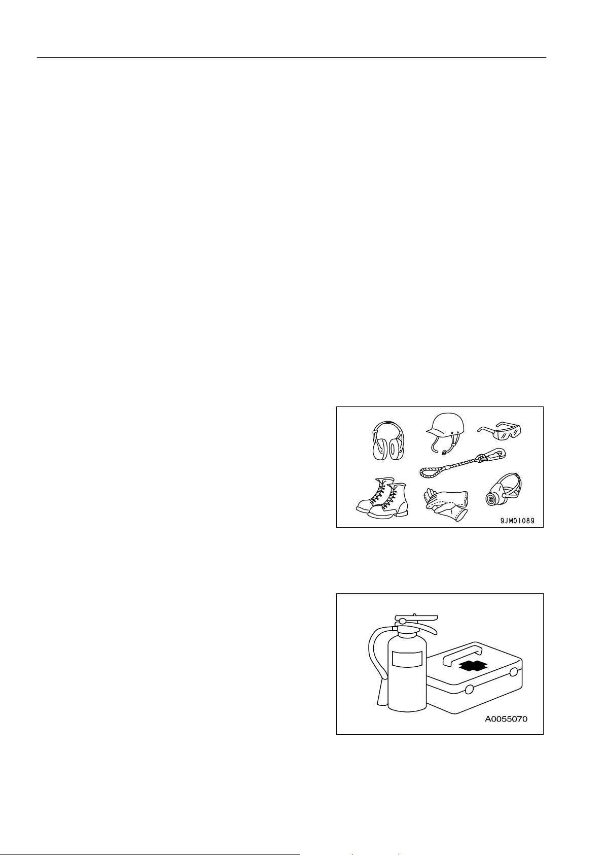
CLOTHING AND PERSONAL PROTECTIVE ITEMS
q Do not wear loose clothing and accessori es. There is a hazard th at they may catch o n control levers or other
protruding parts.
q If you have long hair and it hangs out from your hard hat,
there is a hazard that it may get caught up in the machine,
so tie your hair up and be careful not to let it get caught.
q Always wear a hard hat and safety shoes. If the nature of
the work requires it, wear safety glasses, mask, gloves, ear
plugs, and safety belt when operating or maintaining the
machine.
q Check that all protective equipment functions properly
before using it.
FIRE EXTINGUISHER AND FIRST AID KIT
Always follow the precautions below to prepare for action if any injury or fire should occur.
q Be sure that fire extinguishers have been provided and
read the labels to ensure that you know how to use them in
emergencies.
q Carry out periodic inspection and maintenance to ensure
that the fire extinguisher can always be used.
q Provide a first aid kit at the storage point. Carry out peri-
odic checks and add to the contents if necessary.
2-10
Page 31

SAFETY GENERAL PRECAUTIONS
SAFETY FEATURES
q Be sure that all guards and covers are in their proper position. Have gu ards and cover s rep aired immedi ately if
they are damaged.
q Understand the method of use of safety features and use them properly.
q Never remove any safety features. Always keep them in good operating condition.
KEEP MACHINE CLEAN
q If water gets into the electrical system, there is a hazard
that it will cause malfunctions or misoperation. Do not use
water or steam to wash the electrical system (sensors,
connectors).
q If inspection and maintenance is carried out when the
machine is still dirty with mud or oil, there is a hazard that
you will slip and fall, or that dirt or mud will get into your
eyes. Always keep the machine clean.
INSIDE OPERATOR'S COMPARTMENT
q When entering the operator's compartment, always remove all mud and oil from the soles of your shoes.
If you operate the pedal with mud or oil affixed to your shoes, your fo ot ma y slip an d t his m a y ca us e a ser iou s
accident.
q Do not leave parts or tools lying around the operator's compartment.
q Do not stick suction pads to the window glass. Suction pads act as a lens and may cause fire.
q Do not use cellular telephones inside the operator's compartment when driving or operating the machine.
q Never bring any dangerous objects such as flammable or explosive items into the operator's compartment.
ALWAYS APPLY LOCK WHEN LEAVING OPERATOR'S SEAT
q Before standing up from the operator's seat (such as when
adjusting the operator's seat), lowe r the work equipment
completely to the ground, set safety lock lever (1) and
parking lever (2) securely to the LOCK position, then stop
the engine.
If you accidentally touch the levers when they are not
locked, there is a hazard that the machine may suddenly
move and cause serious injury or property damage.
q When leaving the machine, always lower the work equip-
ment completely to the ground, set safety lock lever (1) and
parking lever (2) securely to the LOCK position, then stop
the engine. Use the key to lock all the equipment. Always
remove the key, take it with you, and keep it in the specified
place.
Free
Lock
Free
Lock
2-11
Page 32

GENERAL PRECAUTIONS SAFETY
HANDRAILS AND STEPS
To prevent personal injury caused by slipping or falling off the machine, always do as follows.
D31PX,D37PX,D39PX,D39EX
q Climb up and down from the operator's cab at the machine
front. Use the handrails and steps marked by arrows in the
diagram on the right when getting on and off the machine.
q Do not climb up and down from the operator's cab at the
machine side or at the rear. A handrail marked by arrow (A)
in the diagram is provided to support yourself when refilling
fuel in the fuel tank. Do not use it for getting on and off the
machine.
D31EX,37EX
q Climb up and down from the operator's cab at the machine
side. Use the handrails and steps marked by arrows in the
diagram on the right when getting on and off the machine.
q Do not climb up and down from the operator's cab at the
machine front or at the rear. A handrail marked by arrow
(A) in the diagram is provided to support yourself when
refilling fuel in the fuel tank. Do not use it for getting on and
off the machine.
2-12
Page 33

SAFETY GENERAL PRECAUTIONS
q To ensure safety, always face the machine and maintain
three-point contact (both feet and one hand, or both hands
and one foot) with the handrails and steps (including the
track shoe) to ensure that you support yourself.
q Do not grip the control levers when getting on or off the
machine.
q Never climb on the engine hood or covers where ther e are
no non-slip pads.
q Before getting on or off the machine, check the handrails
and steps (including the track shoe). If there is any oil,
grease, or mud on the handrails or steps (including the
track shoe), wipe it off immediately. Always keep these
parts clean. Repair any damage and tighten any loose
bolts.
q Do not get on or off the machine while holding tools in your hand.
MOUNTING AND DISMOUNTING
q Never jump on or off the machine. Never get on or off a moving machine.
q If the machine starts to mo ve when there is no operator on the machine , do not jump on to the machine a nd try
to stop it.
NO PEOPLE ON ATTACHMENTS
Never let anyone ride on the work equipment, or other att achments. There is a hazard of falling and suffering serious injury.
CRUSHING OR CUTTING PREVENTION
The clearance around the work equipment will change according to the movement of the link. If you get caught,
this may lead to serious personal injury. Do not allow anyone to approach any rotating or telescoping part.
PREVENTION OF BURNS
Hot coolant
q To prevent burns from hot water or steam spurting out
when checking or draining the coolant, wait for the water to
cool to a temperature where it is pos sib le to to uc h th e ra diator cap by hand before starting the operation. Even when
the coolant has cooled down, loosen the cap slowly to
relieve the pressure inside the radiator before removing the
cap.
Hot oil
q To prevent burns from hot oil spurting out when checking or
draining the oil, wait for the oil to cool to at temperature
where it is possible to touch the cap or plug by hand before
starting the operation. Even when the oil has cooled down,
loosen the cap or plug slowly to relieve the internal pressure before removing the cap or plug.
2-13
Page 34

GENERAL PRECAUTIONS SAFETY
FIRE PREVENTION
q Fire caused by fuel or oil
Fuel, oil, antifreeze, and window washer liquid are particularly flammable and can be hazardous. To prevent fire,
always observe the following:
q Do not smoke or use any flame near fuel or oil.
q Stop the engine be fore refueling.
q Do not leave the machine while adding fuel or oil.
q Tighten all fuel and oil caps securely.
q Do not spill fuel on overheated surfaces or on parts of
the electrical system.
q Use well-ventilated areas for adding or storing oil and
fuel.
q Keep oil and fuel in the determined place and do not
allow unauthorized persons to enter.
q After adding fuel or oil, wipe up any spilled fuel or oil.
q When carrying out grinding or welding work on the
chassis, move any flammable materials to a safe plac e
before starting.
q When washing parts with oil, use a non-flammable oil.
Diesel oil and gasoline may catch fire, so do not use
them.
q Put greasy rags and other flammable materials into a
safe container to maintain safety at the work place.
q Do not weld or use a cutting torch to cut any pipes or
tubes that contain flammable liquids.
q Fire caused by accumulation of flammable material.
Remove any dry leaves, chips, pieces of paper, dust, or any other flammable materials accumulated or affixed
around the engine, exhaust manifold, muffler, or battery, or inside the undercovers.
q Fire coming from electric wiring
Short circuits in the electrical system can cause fire.
q Always keep electric wiring connections clean and securely tightened.
q Check the wiring every day for looseness or damage. Tighten any loose connectors or wiring clamps.
Repair or replace any damaged wiring.
q Fire coming from hydraulic line
Check that all the hose and tube clamps, guards, and cushions are securely fixed in position.
If they are loose, they may vibrate during operation and rub against other parts. This may lead to damage to
the hoses, and cause high-pressure oil to spurt out, leading to fire damage or serious injury.
2-14
Page 35

SAFETY GENERAL PRECAUTIONS
q Explosion caused by lighting equipment
q When checking fuel, oil, battery electrolyte, window washer fluid, or coolant, always use lighting with anti-
explosion specifications. If such lighting equipment is not used, there is danger of explosion that may
cause serious injury.
q When taking the electrical power for the ligh ting fr om the machine it self, follow the instructions in this man-
ual.
ACTION IF FIRE OCCURS
If a fire occurs, escape from the machine as follows.
q Turn the start switch OFF to stop the engine.
q Use the handrails and steps to get off the machine.
WINDOW WASHER LIQUID
Use an ethyl alcohol base washer liquid.
Methyl alcohol base washer liquid may irritate your eyes, so do not use it.
PRECAUTIONS WHEN USING ROPS
Install ROPS when working in places where there is danger of
falling rocks, such as in mines and quarries, or in places where
there is danger of rolling over.
q If ROPS is installed, do not remove it when operating the
machine.
q ROPS is installed to protect the operator when machine
rolls over. When machine rolls over, ROPS supports its
weight and absorbs its impact energy.
q If ROPS is modified, its strength may be reduced. When
modifying, consult your Komatsu distributor.
q If ROPS is damaged or deformed by falling objects or by rolling over, it s strength will be reduced and it will not
be able to fulfill its function properly. In such cases, always Komatsu contact your distributor for advice of the
method of repair.
Even if ROPS is installed, always fasten your seat belt properly when operatin g the machine. If you do not use
your fasten your seat belt properly, it cannot display its effect.
PRECAUTIONS FOR ATTACHMENTS
q When installing optional parts or attachments, there may be problems with safety or legal restrictions. There-
fore contact your Komatsu distributor for advice.
q Any injuries, accidents, or product failures resulting from the use of unauthorized attachments or parts will not
be the responsibility of Komatsu.
q When installing and using optional attachments, read the instruction manual for the attachment, and the gen-
eral information related to attachments in this manual.
UNAUTHORIZED MODIFICATION
Any modification made without authorization from Komatsu can create hazards. Before making a modification,
consult your Komatsu distributor.
q Komatsu will not be responsible for any injuries, accidents, product failures or other property damages result-
ing from modifications made without authorization from Komatsu.
2-15
Page 36

GENERAL PRECAUTIONS SAFETY
SAFETY AT WORKSITE
Before starting operations, thoroughly check the area for any unusual conditions that could be dangerous.
q When carrying out operations near combustible materials such as thatched roofs, dry leaves or dry grass,
there is a hazard of fire, so be careful when operating.
q Check the terrain and condition of the ground at the worksite, and determine the safest method of operation.
Do not carry out operations at places where there is a hazard of landslides or falling rocks.
q If water lines, gas lines, or high-voltage electrical lines may
be buried under the worksite, contact each utility and identify their locations. Be careful not to sever or damage any
of these lines.
q Take action to prevent unauthorized people from approach-
ing the jobsite.
When working on public roads, position flagmen and erect
barriers to ensure the safety of passing traffic and pedestrians.
q When traveling or operating in shallow water or on soft
ground, check the shape and condition of the bedrock, and
the depth and speed of flow of the water before starting
operations.
WORKING ON LOOSE GROUND
q Avoid traveling or operating your machine too close to the edge of cliffs, overhangs, and deep ditches. The
ground may be weak in such areas. If the ground should collapse under the weight or vibra tion of the machine,
there is a hazard that the machine may fall or tip over. Remember that the soil after heavy rain or blasting or
after earthquakes is weak in these areas.
q When working on embankments or near excavated ditches, there is a hazard that the weight and vibration of
the machine will cause the soil to collapse. Before starting operations, take steps to ensure that the ground is
safe and to prevent the machine from rolling over or falling.
DO NOT GO CLOSE TO HIGH-VOLTAGE CABLES
Do not travel or operate the machine near electric cables. There is a hazard of electric shock, which may cause
serious injury or property damage. On jobsites where the machine may go close to electric cables, always do as
follows.
q Before starting work near electric cables, inform the local power company of the work to be performed, and
ask them to take the necessary action.
q Even going close to high-voltage cables can cause electric
shock, which may cause serious burns or even death.
Always maintain a safe distance (see the table on the right)
between the machine and the electric cable. Check with
the local power company about safe operating procedure
before starting operations.
q To prepare for any possible emergencies, wear rubber
shoes and gloves. Lay a rubber sheet on top of the seat,
and be careful not to touch the chassis with any exposed
part of your body.
Voltage of Cables Safety Distance
100 V - 200 V Over 2 m
6,600 V Over 2 m
22,000 V Over 3 m
66,000 V Over 4 m
154,000 V Ove r 5 m
187,000 V Ove r 6 m
275,000 V Ove r 7 m
500,000 V Over 11 m
q Use a signalman to give warning if the machine
approaches too close to the electric cables.
q When carrying out operations near high voltage cables, do
not let anyone come close to the machine.
2-16
Page 37

SAFETY GENERAL PRECAUTIONS
q If the machine should come too close or touch the electric cable , to prevent electric sh ock, the operato r should
not leave the operator's compartment until it has been confirmed that the electricity has been shut off.
Also, do not let anyone come close to the machine.
ENSURE GOOD VISIBILITY
Check for any persons or obstacles in the area around the machine and check the conditions of the jobsite to
ensure that operations and travel can be carried out safely. Always do as follows.
q Position a signalman if there are areas at the rear of the machine where the visibility is not good.
q When working in dark places, turn on the working lamp and front lamps installed to the machine, and set up
additional lighting in the work area if necessary.
q Stop operations if the visibility is poor, such as in mist, snow, rain, or dust.
VENTILATION FOR ENCLOSED AREAS
Exhaust fumes from the engine can kill.
q If it is necessary to start the engine within an enclosed
area, or when handling fuel, flushing oil, or paint, open the
doors and windows to ensure that adequate ventilation is
provided to prevent gas poisoning.
CHECKING SIGNALMAN'S SIGNALS AND SIGNS
q Set up signs to inform of road shoulders and soft ground. If the visibility is not good, position a signalman if
necessary. Operators should pay careful attention to the signs and fo llow the instructions from the signalman.
q Only one signalman should give signals.
q Make sure that all workers understand the meaning of all signals and signs before starting work.
EMERGENCY EXIT FROM OPERATOR'S CAB
Machines equipped with a cab have doors on the left and right sides. If the door on the one side does not open,
escape from the door on the other side.
2-17
Page 38

GENERAL PRECAUTIONS SAFETY
BE CAREFUL ABOUT ASBESTOS DUST
Asbestos dust in the air can cause lung cancer if it is inhaled.
There is danger of inhaling asbestos when working on jobsites
handling demolition work or work handling industrial waste.
Always observe the following.
q Spray water to keep down the dust when cleaning. Do not
use compressed air for cleaning.
q If there is danger that there may be asbestos dust in the
air, always operate the machine from an upwind position.
All workers should use an approved respirator.
q Do not allow other persons to approach durin g the opera-
tion.
q Always observe the rules and re gulations for the work site
and environmental standards.
This machine does not use asbestos, but there is a danger that imitation parts may contain asbestos, so always
use genuine Komatsu parts.
2-18
Page 39

SAFETY PRECAUTIONS FOR OPERATION
PRECAUTIONS FOR OPERATION 2
STARTING ENGINE 2
If there is a warning tag hanging from the work equip men t control lever, do not start the engine or touch the levers .
CHECKS BEFORE STARTING ENGINE
Carry out the following checks before starting the engine at the beginning of the day's work.
q Remove all dirt from the surface of the window glass to ensure a good view.
q Remove all dirt from the surface of the lens of the front lamps and working lamps, and check that they light up
correctly.
q Check the coolant level, fuel level, and oil level in engine oil pan, check for clogging of the air cleaner, and
check for damage to the electric wiring.
q Adjust the operator's seat to a position where it is easy to carry out operations, and check that there is no dam-
age or wear to the seat belt or mounting clamps.
q Check that the gauges work properly, check the angle of the lights and working lamp s, and che ck th at the con-
trol levers are all at the neutral position.
q Adjust the mirror to a position which gives a good view to the rear from the operator's seat.
q Check that there are no persons or obstacles above, below, or in the area around the machine.
PRECAUTIONS WHEN STARTING
q Start and operate the machine only while seated.
q Do not attempt to start the engine by short-circuiting the engine starting circuit. Such an act may cause a seri-
ous bodily injury or fire.
q When starting the engine, sound the horn as a warning.
q Do not allow anyone apart from the operator to ride on the machine.
2-19
Page 40

PRECAUTIONS FOR OPERATION SAFETY
PRECAUTIONS IN COLD AREAS
q Carry out the warming-up operation thoroughly. If the machine is not thoroughly warmed up before the control
levers are operated, the reaction of the machine will be slow, and this may lead to unexpected accidents.
q If the battery electrolyte is frozen, do not charge the battery or start the engine with a different power source.
There is a hazard that this will ignite the battery and cause the battery to explode.
Before charging or starting the engine with a dif ferent powe r source, melt the battery electrolyte and ch eck that
there is no leakage of electrolyte before starting.
2-20
Page 41

SAFETY PRECAUTIONS FOR OPERATION
OPERATION 2
CHECKS BEFORE OPERATION
When carrying out the checks, move the machine to a wide area where there are no obstructions, and operate
slowly. Do not allow anyone near the machine.
q Always fasten your seat belt.
q Check the operation of travel, steering and brake systems,
and work equipment control system.
q Check for any abnormality in the sound of the machine,
vibration, heat, smell, or gauges; check also that there is
no leakage of oil or fuel.
q If any abnormality is found, carry out repairs immediately.
PRECAUTIONS FOR MOVING MACHINE FORWARD OR IN REVERSE
q Before travelling, check again that there is no one in the
surrounding area, and that there are no ob s tacles .
q Before travelling, sound the horn to warn people in the
area.
q Always operate the machine only when seated.
q Do not allow anyone apart from the operator to ride on the
machine.
q Check that the back-up alarm (alarm buzzer when machine
travels in reverse) works properly.
q Fix the operator's compartment doors and windows in posi-
tion securely.
q If there is an area to the rear of the machine which cannot
be seen, position a signal person. Take special care not to
hit other machines or people when turning or swinging the
machine.
Always be sure to carry out the above precautions even when
the machine is equipped with mirrors.
PRECAUTIONS WHEN TRA VELING
q When traveling on level ground, keep the work equipment
at a height of 40 to 50 cm from the ground.
q When traveling on rough ground, travel at low speed and
do not operate the steering suddenly. There is danger that
the machine may turn over. The work equipment may hit
the ground surface and cause the machine to lose its balance, or may damage the machine or structures in the
area.
2-21
Page 42

PRECAUTIONS FOR OPERATION SAFETY
q Avoid traveling over obstacles when possible. If the
machine has to travel over an obstacle, keep t he work
equipment close to the ground and travel at low speed.
Never travel over obstacles which make the machine tilt
strongly to one side.
q When traveling or carrying out operations, always keep a
safe distance from people, structures, or other machines to
avoid coming into contact with them.
q When passing over bridges or structures, check first that
the structure is strong enough to support the weight of the
machine. When traveling on public roads, check first with
the relevant authorities and follow their instructions.
q When operating in tunnels, under bridges, under electric
wires, or other places where the height is limited, operate
slowly and be extremely careful not to let the work equipment hit anything.
q Do not approach the edge of a cliff carelessly. When dropping soil over a cliff for banking or reclamation, leave
soil of one scoop at the edge of the cliff and push it with the next scoop.
q When the machine passes over the to p of a hill or when a load is dumped ov er a cliff, the load is suddenly
reduced, and there is danger that the travel speed rises suddenly. To prevent this, lower the travel speed.
q If the machine moves with only either side of the blade loaded, its tail may swing. Take care.
TRAVELING ON SLOPES
To prevent the machine from tipping over or slipping to the side, always do as follows.
q Keep the work equipment approx. 20 to 30 cm above the
ground. In case of emergency , lower the work equipment to
the ground immediately to help stop the machine.
q When traveling down a slope, always place the transmis-
sion in low speed and travel down the slope slowly.
q Always travel straight up or down a slope. Traveling at an
angle or across the slope is extremely dangerous.
q Do not turn on slopes or travel across slopes. Always go
down to a flat place to change the position of the machine,
then travel on to the slope again.
q Travel on grass, fallen leaves, or wet steel plates with low
speed. Even with slight slopes there is a hazard that the
machine may slip.
USING BRAKES
q Use the deceleration pedal or speed shift switch to adjust the speed. If the brake pedal is suddenly
depressed, the mechanical brake is applied to stop the machine sudde nly, but this is dangerous if the machine
is traveling too fast.
q When traveling downhill, set the travel speed to a low speed and use the engine as a brake.
2-22
Page 43

SAFETY PRECAUTIONS FOR OPERATION
OPERATE CAREFULLY ON SNOW
q Snow-covered or frozen surfaces are slippery, so be extremely careful when traveling or operating the
machine, and do not operate the levers suddenly. Even a slight slope may cause the machine to slip, so be
particularly careful when working on slopes.
q With frozen ground surfaces, the ground becomes soft when the temperature rises, and this may cause the
machine to tip over.
q If the machine enters deep snow, the re is a hazard that it may tip over or be come bu rie d in the sn ow. Be care-
ful not to leave the road shoulder or to get trapped in a snow drift.
q When clearing snow, the road shoulder and objects placed beside the road ar e buried in the snow and cannot
be seen. There is a hazard of the machine tipping over or hitting covered objects, so always carry out operations carefully.
q When operating on slow-covered slopes, never use the brakes to stop the machine suddenly. Reduce the
speed and use the engine as a brake together with operat ing the brake p edal. If ne cessary, lower the blade to
the ground to stop the machine.
PARKING MACHINE
q Park the machine on firm, level ground.
q Select a place where there is no hazard of falling rocks or
landslides, or of flooding if the land is low.
q Lower the work equipment completely to the ground.
q When leaving the machine, set the steering, directional
and gear shift levers in the N (Neutral) position an d set the
blade lever in the HOLD position, then apply safety lock
lever (1) and parking lever (2) and stop the engine.
q Always close the operator's cab door, and use the key to
lock all the equipment in order to prevent any unauthor ized
person from moving the ma chine . Alwa ys rem ove the key,
take it with you, and leave it in the specified place.
q If it is necessary to park the machine on a slope, a lwa ys do
as follows.
q Set the blade on the downhill side, then dig it into the
ground.
Block
Free
Lock
Free
Lock
q Put blocks under the tracks to prevent the machine
from moving.
Dig it
Block
2-23
Page 44

PRECAUTIONS FOR OPERATION SAFETY
TRANSPORTATION 2
LOADING AND UNLOADING
When loading or unloading the machine, mistaken operation
may bring the hazard of the machine tipping over or falling, so
particular care is necessary. Always do as follows.
q Perform loading and unloading on firm, level ground only.
Maintain a safe distance from the edge of the road or cliff.
q Always use ramps of adequate strength. Be sure that the
ramps are wide, long, and thick enough to provide a safe
loading slope. Take suitable steps to prevent the ramps
from moving out of position or coming off.
q Be sure the ramp surface is clean and free of grease, oil,
ice and loose materials. Remove dirt from machine-tr acks.
On a rainy day, in particular, be extremely careful since the
ramp surface is slippery.
q Run the engine at low speed and travel slowly.
q When on the ramps, do not touch any other parts.
Ramp
Distance
between ramps
Max 15°C
Blocks
Block
q Never correct your steering on the ramps. If necess ary, drive off the ramps, correct the direction, then enter
the ramps again.
q The center of gravity of the machine will chenge suddenly at the joint between the ramps and the track or
trailer, and there is danger of the machine losing its balance. Travel slowly over this point.
q When loading or unloading to an emb ankment or platform, make sure th at it has suitable width, streng th, and
grade.
q For machines equipped with a ca b, always lock the door after boarding th e machine. If this is not done, the
door may suddenly open during transportation.
Refer to “TRANSPORTATION (3-103)“.
SHIPPING
When shipping the machine on a trailer, do as follows.
q The weight, transportation height, and overall length of the machine differ according to the work equipment, so
be sure to confirm the dimensions.
q When passing over bridges or structures on private land, check first that the structu re is stron g enough to sup-
port the weight of the machine. When traveling on public roads, check first with the relevant authorities and follow their instructions.
q For details of the shipping procedure, see “TRANSPORTATION (3-103)“ in the OPERA TION section.
2-24
Page 45

SAFETY PRECAUTIONS FOR OPERATION
BATTERY 2
BATTERY HAZARD PREVENTION
Battery electrolyte contains sulphuric acid, and batteries generate flammable hydrogen gas, which may explode.
Mistaken handling can lead to serious injury or fire. For this reason, always observe the following precautions.
q Do not use or charge the battery if the battery electrolyte level is below the LOWER LEVEL line. This may
cause an explosion. Always check the battery electrolyte level periodically and add distilled water to bring the
electrolyte level to the UPPER LEVEL line.
q When working with batteries, always wear safety glasses and rubber gloves.
q Never smoke or use any flame near the battery.
q If you spill acid on your clothes or skin, immediately flush
the area with large amount of water.
q If acid gets into your eyes, flush them immediately with
large amount of water and seek medical attention.
q Before working with batteries, turn the starting switch to the OFF position.
As there is a hazard that sparks will be generated, always do as follows.
q Do not let tools or other metal objects make any contact betw een the batter y terminals. Do not le ave tools or
other metal objects lying around near the battery.
q Always disconnect the negative (-) terminal (ground side) first when removing the battery; when installing the
battery, connect the positive (+) terminal first, and connect the ground last. Tighten the battery terminals
securely.
q Flammable hydrogen gas is generated when the battery is charged, so remove the battery from the chassis,
take it to a well-ventilated place, and remove the battery caps before charging it.
q Tighten the battery caps securely.
q Install the battery securely to the determined place.
2-25
Page 46

PRECAUTIONS FOR OPERATION SAFETY
STARTING WITH BOOSTER CABLE
If any mistake is made in the method of connecting the booster
cables, it may cause the battery to explode, so always do as
follows.
q When starting with a booster cable, carry out the starting
operation with two workers (one worker sitting in the operator's seat and the other working with the battery).
q When starting from another machine, do not al low the two
machines to touch.
q When connecting the booster cables, turn the starting
switch OFF for both the normal machine and problem
machine. There is a hazard that the machine will move
when the power is connected.
q Be sure to connect the positive (+) ca ble first when install-
ing the booster cables. Disconnect the negative (-) cable
(ground side) first when removing them.
q When removing the booster cables, be careful not to let the
booster cable clips touch each other or to let the clips touch
the machine.
q Always wear safety goggles and rubber gloves when start-
ing the engine with booster cables.
q When connecting a normal machine to a problem machine
with booster cables, always use a normal machine with the
same battery voltage as the problem machine.
q For details of the starting procedure when using booster
cables, see “STARTING ENGINE WITH BOOSTER
CABLE (3-122)“ in the OPERATION section.
2-26
Page 47

SAFETY PRECAUTIONS FOR OPERATION
TOWING 2
WHEN TOWING
Serious injury or death could result if a disabled machine is towed incorrectly or if there is a mistake in the selection or inspection of the wire rope.
For towing method, see section “MACHINE TOWING METHOD (3 -113)“.
q Always wear leather gloves when handling wire rope.
q Connect a wire rope to the part indicated with the arrow in
the diagram at right.
q During the towing operation, never stand between the tow-
ing machine and the machine being towed.
q Never tow a machine on a slope.
q Never pull the towing equipment up or insert a pedestal.
q Never use a wire rope which has cut strands (A), reduced
diameter (B), or kinks (C). There is danger that the rope
may break during the towing operation.
q If the engine stops or the oil pressure in the brake circuit lowers because of a trouble in the brake valve sole-
noid, the brake works and the machine cannot move. To move the machine in this case, the oil pressure in the
brake circuit must be heightened to the specified level with a special device. Ask your Komatsu distributor.
2-27
Page 48

PRECAUTIONS FOR MAINTENANCE SAFETY
PRECAUTIONS FOR MAINTENANCE 2
WARNING TAG
q Always attach the “DO NOT OPERATE“ warning tag to the
work equipment control lever in the operator's cab to alert
others that you are performing service or maintenance on
the machine. Attach additional warning tags around the
machine if necessary.
Warning tag Part No. 09963-A1640
Keep this warning tag in the tool box while it is not used. If
there is not the tool box, keep the tag in the operation m anual pocket.
q If others start the engine, or touch or operate the work
equipment control lever while you are performing service
or maintenance, you could suffer serious injury or property
damage.
KEEP WORK PLACE CLEAN AND TIDY
Do not leave hammers or other tools lying around in the work place. Wipe up all grease, oil, or other substances
that will cause you to slip. Always keep the work place clean the tidy to enable you to carry out operations safely.
If the work place is not kept claen and tidy , there is the danger that you will trip, slip, or fall over and injure yourself.
APPOINT LEADER WHEN WORKING WITH OTHERS
When repairing the machine or when removing and installing the work equipment, appoint a leader and follow his
instructions during the operation.
When working with others, misunderstandings between workers can lead to serious accidents.
STOP ENGINE BEFORE CARRYING OUT INSPENTION AND MAINTENANCE
q Stop the machine on firm, level ground.
q Select a place where there is no hazard of falling rocks or
landslides, or of flooding if the land is low.
q Lower the work equipment completely to the ground and
stop the engine.
q Open the engine side cover all the way and ensure that it is
locked open before letting go.
2-28
Page 49

SAFETY PRECAUTIONS FOR MAINTENANCE
q Set safety lock lever (1) and parking lever (2) to the LOCK
position.
Free
Lock
Free
Lock
q Put blocks under the track to prevent the machine from
moving.
Block
TWO WORKERS FOR MAINTENANCE WHEN ENGINE IS RUNNING
To prevent injury , do not carry out maintenance with the engine
running. If maintenance must be carried out with the engine
running, carry out the operation with at least two workers and
do as follows.
q One worker must always sit in the operator's seat and be
ready to stop the engine at any time. All workers must
maintain contact with the other workers.
q Set safety lock lever (1) and parking lever (2) to the LOCK
position.
q When carrying out operations near the fan, fan belt, or
other rotating parts, there is a hazard of being caught in the
Free
parts, so be careful not to come close.
q Do not touch any control levers. If any control lever must
be operated, give a signal to the other worke rs to warn
them to move to a safe place.
q Never drop or insert tools or other ob jects into the fan or
fan belt. Parts may break or be sent flying.
Lock
Free
Lock
2-29
Page 50

PRECAUTIONS FOR MAINTENANCE SAFETY
PROPER TOOLS
Use only tools suited to the task and be sure to use the tools
correctly. Using damaged, low quality, faulty, makeshift tools or
improper use of the tools could cause serious personal injury.
ACCUMULATOR
The accumulator is charged with high-pressure nitrogen gas.
When handling the accumulator, careless procedure may
cause an explosion which could lead to serious injury or property damage. For this reason, always observe the following
precautions.
q Do not disassemble the accumulator.
q Do not bring it near flame or dispose of it in fire.
q Do not make holes in it, weld it, or use a cutting torch.
q Do not hit or roll the accumulator, or subject it to any
impact.
q When disposing of the accumulator, the gas must be
released. Please contact your Komatsu distributor to have
this work performed.
NO UNAUTHORIZED PERSONNEL INTO AREA
Only authorized personnel can service and repair the machine. Do n ot allow unauthorized personnel into the
area. If necessary, employ an observer.
ATTACHMENTS
q Appoint a leader before starting removal or installation
operations for attachments.
q Place attachments that have been removed from the
machine in a stable condition so that they do not fall. And
take steps to prevent unauthorized persons from entering
the storage area.
2-30
Page 51

SAFETY PRECAUTIONS FOR MAINTENANCE
WORK UNDER THE MACHINE
q If it is necessary to go under the work equipment or the
machine to carry out service and maintenance, support the
work equipment and machine securely with blocks and
stands strong enough to support the weight of the work
equipment and machine.
q It is extremely dangerous to work under the machine if the
track shoes are lifted off the ground and the machine is
supported only with the work equipment. If any of the control levers is touched by accident, or there is damage
occurring to the hydraulic piping, the work equipment or th e
machine will suddenly drop. This is extremely dangerous.
Never work under the work equipment or the machine.
NOISE
If the noise from the machine is too loud, it may cause temporary or permanent hearing problems. When carrying
out maintenance of the engine and you are exposed to noise for long pe riods of time, we ar ea r co vers o r ear plugs
while working.
PRECAUTIONS WHEN USING HAMMER
When using a hammer, pins may fly out or metal particles may
be scattered. This may lead to serious injury. Always do as
follows.
q If hard metal parts such as pins, bucket teeth, cutting
edges, or bearings are hit with a hammer, there is a hazard
that pieces might be scattered and cause injury. Always
wear safety goggles and gloves.
q When hitting pins or bucket teeth, there is a hazard that
broken pieces might be sent flying an d injure peop le in the
surrounding area. Always check that there is no one in the
surrounding area.
q There is a hazard that the pin hit with strong force may fly out and injure people in the surrounding area.
REPAIR WELDING
Welding operations must always be carried out by a qualified welder and in a place equipped with prop er equipment. There is a hazard of gas, fire, or electrocution when carrying out welding, so never allow any unqualified
personnel to carry out welding.
REMOVING BATTERY TERMINAL
When repairing the electrical system or when carrying out electrical welding, remove the negative (-) terminal of
the battery to prevent the flow of current.
2-31
Page 52

PRECAUTIONS FOR MAINTENANCE SAFETY
PRECAUTIONS WHEN USING HIGH-PRESSURE GREASE TO ADJUST TRACK TENSION
q Grease is pumped into the track tension adjustment sys-
tem under high pressure.
If the specified procedure for maintenance is not followed
when making adjustment, grease drain plug (1) may fly out
and cause serious injury or property damage.
q When loosening grease drain plug (1) to loosen the track
tension, never loosen it more than one turn. Loosen the
grease drain plug slowly.
q Never put your face, hands, feet, or any other part of your
body close to grease drain plug (1).
DO NOT DISASSEMBLE RECOIL SPRING
Never attempt to disassemble the recoils spring assembly. It contains a spring under high pressure which serves
as a shock absorber for the idler. If it is disassembled by mistake, the spring will fly out and cause serious injury.
When it becomes necessary to disassemble it, ask your Komatsu distributor to do the work.
PRECAUTION WITH HIGH-PRESSURE OIL
The hydraulic system is always under internal pressure. When inspecting or replacing piping or hoses, always
check that the pressure in the hydraulic circuit has been released. If the circuit is still under pressure, it will lead to
serious injury, so always do as follows.
q For the procedure to release internal pressure, see “PROCEDURE FOR RELEASING INTERNAL PRES-
SURE OF HYDRAULIC SYSTEM (4-35)“. Do not inspect or replace any part while internal pressure is
applied.
q If there is any leakage from the piping or hoses, the surrounding area will be wet, so check for cracks in the
piping and hoses and for swelling in the hoses.
When carry out inspection, wear safety glasses and leather gloves.
q There is a hazard that high-pressure oil leaking from small
holes may penetrate your skin or cause blindness if it contacts your eyes directly. If you are hit by a jet of high-pressure oil and suffer injury to your skin or eyes, wash the
place with clean water, and consult a doctor immediately
for medical attention.
2-32
Page 53

SAFETY PRECAUTIONS FOR MAINTENANCE
HANDLING HIGH-PRESSURE HOSES
q If oil or fuel leaks from high-pressure hoses, it may cause fire or defective operation, which may lead to serious
injury. If any loose bolts are found, stop work and tighten to the specified torque. If any damaged hoses are
found, stop operations immediately and contact your Komatsu distributor.
Replace the hose if any of the following problems are found.
q Damaged or leaking hydraulic fitting.
q Frayed or cut covering or exposed reinforcement wire layer.
q Covering swollen in places.
q Twisted or crushed movable portion.
q Foreign material embedded in covering.
WASTE MATERIAL
To prevent pollution, pay careful attention to the method of disposing of waste materials.
q Always put oil drained from your machine in containers.
Never drain oil directly onto the ground or dump into the
sewage system, rivers, the sea, or lakes.
q Obey appropriate laws and regulations when disposing of
harmful objects such as oil, fuel, coolant, solvent, filters,
and batteries.
MAINTENANCE FOR AIR CONDITIONER
If air conditioner refrigerant gets into your eyes, it may cause blindness; if it touches your skin, it may cause frostbite.
Never touch refrigerant.
COMPRESSED AIR
q When carrying out cleaning with compressed air, there is a hazard of serious injury caused by flying particles.
q When using compressed air to clean element s or the radi ator, always wear safety goggles, dust mask, gloves,
and other protective equipment.
PERIODIC REPLACEMENT OF SAFETY CRITICAL PARTS
q In order for the machine to be operated safety for a long time, it is necessary to add oil and to carry out service
and maintenance at periodic intervals. In order to furthe r increase safety, components with a strong relationship to safety, such as hoses and seat belts, must be replaced at periodic intervals.
Replacement of safety critical parts: See “PERIODIC REPLACEMENT OF SAFETY CRITICAL PARTS (4-
16)“.
q The material of these components naturally changes over time, and repeated use causes deterioration, wear,
and fatigue. As a result, there is a hazard that these components may fail and cause serious injury or death.
It is difficult to judge the remaining life of these components from external inspection or the feeling when operating, so always replace them at the specified interval.
q Replace or repair safety-critical parts if any defect is found, even when they have not reached the time speci-
fied interval.
2-33
Page 54

PRECAUTIONS FOR MAINTENANCE SAFETY
2-34
Page 55

OPERATION
13
WARNING
Please read and make sure that you understand the safety
volume before reading this section.
Page 56

GENERAL VIEW OPERATION
GENERAL VIEW 3
GENERAL VIEW OF MACHINE 3
Machine equipped with canopy
Machine equipped with cab
(1) Blade (7) Track frame
(2) Angle cylinder (8) Lift cylinder
(3) Radiator mask (9) Idler
(4) Canopy (10) Frame
(5) Track shoe (11) Cab
(6) Sprocket
3-2
Page 57

OPERATION GENERAL VIEW
GENERAL VIEW OF CONTROLS AND GAUGES 3
(1) Fuel control lever (11 ) Horn switch
Joystick (Steering, directional and gear shift
(2)
lever)
(3) Information switch (13) Brake pedal
(4) Buzzer cancel switch (14) Safety lock lever
(5) Lamp switch (15) Parking lever
(6) Monitor panel (16) Wiper switch (machine equipped with cab)
(7) Reverse travel speed setting switch (17) Room lamp switch (machine equipped with cab)
(8) Shift mode switch
(9) Starting switch
(10) Blade control lever (19) Cigarette lighter (machine equipped with cab)
(12) Decelerator pedal
(18) Wiper motor breaker reset button (machine
equipment with cad)
3-3
Page 58

GENERAL VIEW OPERATION
MONITOR PANEL
Display panel A (Speed range, Set travel speed,
(1)
Shift mode Indicator)
(9) Filter/oil replacement interval lamp
(2) HST oil temperature gauge (10) Warning lamp
(3) Engine coolant temperature gauge (11) Engine coolant temperature caution lamp
(4) Reverse travel speed indicator (12) Maintenance caution lamp
(5) Fuel level gauge (13) Engine preheating pilot lamp
(6) Charge filter clogging caution lamp (14) Engine oil pressure caution lamp
(7) HST charge pressure caution lamp (15) Battery charge circut caution lamp
(8) HST oil temperature caution lamp (16) Display panel B (Multi-information)
3-4
Page 59

OPERATION EXPLANATION OF COMPONENTS
EXPLANATION OF COMPONENTS 3
The following is an explanation of the devices needed for operating the machine.
To perform suitable operations correctly and safely, it is important to completely understand the methods of operat-
ing equipment and meanings of the displays.
FRONT PANEL 3
(A) Emergency caution group (D) Lamp
(B) Caution group (E) Switch
(C) Meter group
3-5
Page 60

EXPLANATION OF COMPONENTS OPERATION
CHECK MONITOR SYSTEM 3
MONITOR SYSTEM
NOTICE
q Stop the machine on level ground and carry out the monitor check.
q Stop the engine, then turn the st arting switch to the ON position and check that the lamps light up for
approx. 2 seconds. If they do not light up, please ask your Komatsu distributor to carry out inspection.
q The monitor check cannot be carried out until at least 5 seconds has passed after the engine was
stopped.
When carrying out the checks before starting, use the monitor system check.
1. Turn the starting switch to the ON position.
2. Check that the monitor liquid-crystal display and the lamps
all light up for 2 seconds, that the alarm buzzer sounds for
2 seconds, and that “KOMATSU SYSTEM CHECK“ is displayed for 3 seconds on display panel B (multi-information)
(1).
q After 2 seconds, the current status of the machine is
displayed on liquid-crystal display (2).
q After 2 seconds, the lamp portion (3) goes out.
q After 3 seconds, the operating mode is displayed on
display panel B (multi-information) (1).
REMARK
The following cases do not indicate any abnormality.
When the replacement interval is reached for the oil and filter,
maintenance caution lamp (4) and filter/oil replacement interval
lamp (5) light up or flash for 30 seconds, and the action code is
displayed on display panel B (multi-information) (1).
3-6
Page 61

OPERATION EXPLANATION OF COMPONENTS
EMERGENCY CAUTION ITEMS 3
CAUTION
If any of the caution lamps begins to flash, s top the en gine or redu ce the engine speed t o low idling immediately and check the trouble spot for necessary actions.
These items must be monitored when the engine is running. If there is any abnormality, the caution lamp for the
location of the abnormality and warn ing la mp ( A) fl ash, and the a larm buzz er so und s inte rmitten tly. Take the necessary action immediately.
(1) Engine oil pressure caution lamp (4) Charge filter clogging caution lamp
(2) Engine coolant temperature caution lamp (5) HST charge pressure caution lamp
(3) HST oil temperature caution lamp
ENGINE OIL PRESSURE CAUTION LAMP
This lamp (1) indicates a low engine oil pressure.
If the monitor lamp flashes, stop the engine and check it imme-
diately.
REMARK
The alarm buzzer sounds, when the starting switch is turned to
ON immediately after the engine oil has been changed. It does
not indicate an abnormality.
3-7
Page 62

EXPLANATION OF COMPONENTS OPERATION
ENGINE COOLANT TEMPERATURE CAUTION LAMP
This lamp (2) indicates a raise in the coolant temperature.
When the monitor lamp flashes, run the engine at low idling
speed until green range of the engine coolant temperature
gauge lights.
HST OIL TEMPERATURE CAUTION LAMP
This lamp (3) warns the operator that the HST oil temperature
has gone up.
If it flashes, run the engine at low idling until the HST oil temperature gauge indicates the green ra ng e .
CHARGE FILTER CLOGGING CAUTION LAMP
This lamp (4) warns the operator that the HST charge filter is
clogged.
If it flashes, stop the m achine, check for t he ca use of clogg ing,
and replace the filter element with a new part.
HST CHARGE PRESSURE CAUTION LAMP
This lamp (5) warns the operator that the HST charge pressure
has dropped.
If it flashes, stop the machine and check for the cause of the
drop in the charge pressure.
3-8
Page 63

OPERATION EXPLANATION OF COMPONENTS
CAUTION CAUTION ITEMS 3
CAUTION
If these caution lamps item flash, check and repair the appropriate location as soon as possible.
These are items which need to be observed when the engine is running. If any abnormality occurs, the item needing immediate repair is displayed. If there is any abnormality, the abnormal location on the caution lamp will flash.
(1) Battery charge circut caution lamp (2) Maintenance caution lamp
BATTERY CHARGE CIRCUIT CAUTION LAMP
This lamp (1) indicates an abnormality in the charging system
while the engine is running.
If the monitor lamp flashes, check the V-belt tension. If any
abnormality is found, see “OTHER TROUBLE (3-125)“.
REMARK
This monitor lamp lights when the ignition switch is turned to
ON immediately after the engine is started or immediately
before the engine is stopped. It does not indicate an abnormality.
3-9
Page 64

EXPLANATION OF COMPONENTS OPERATION
MAINTENANCE CAUTION LAMP
This lamp (2) lights up for approx. 30 seconds after the starting
switch is turned to the ON position if the filter or oil replacement
interval has been reached.
After replacing the indicated filter or oil displayed on display
panel B (multi-information), reset the interval. For details, see
“METHOD OF USING OIL AND FILTER MAINTENANCE
MODE (3-23)“.
The lamp goes out.
REMARK
At the same time, the filter or oil replacement interval lamp also
lights up or flashes.
3-10
Page 65

OPERATION EXPLANATION OF COMPONENTS
METER GROUP 3
(1) Engine coolant temperature gauge (6)
(2) HST oil temperature gauge
(3) Fuel level gauge (7) Display panel B (Multi-information)
(4) Engine preheating pilot lamp (8) Reverse travel speed setting switch
(5) Reverse travel speed indicator (9) Shift mode switch
ENGINE COOLANT TEMPERATURE GAUGE
NOTICE
If the coolant temperature gauge often ent ers red range (C), check the radiator for clogging.
Gauge (1) indicates temperature of the engine coolant.
If the temperature is normal during operation , green range ( B)
will light.
If red range (C) lights during operation, move the fuel control
lever to lower engine speed tp approx. 3/4 of the full speed,
and run until the coolant temperature enters green range (B).
If red range (C) lights up during operation , and th e e ngine coo lant temperature caution lamp flashes and the alarm buzzer
sounds, stop the machine, run the engine at low idle, and wait
for the coolant temperature to return to green range (B).
Display panel A (Speed range, Set travel speed,
Shift mode Indicator)
(A): White range
(B): Green range
(C): Red range
3-11
Page 66

EXPLANATION OF COMPONENTS OPERATION
HST OIL TEMPERATURE GAUGE
NOTICE
If the HST oil temperature gauge frequently enters red range (C), che ck for clogging of the oil cooler.
This meter (2) displays the oil t emper atur e in the p ump suc tion
piping.
Green range (B) should be lighted up durin g normal operations.
If red range (C) lights up during operation, move the fuel control lever to lower engine speed to approx. 3/4 of the full spee d,
reduce the load and run until the oil temperature enters green
range (B).
If red range (C) lights up during operation, and the HST oil temperature caution lamp flashes and the alarm buzzer sounds,
stop the machine, run the engine at low idle, and wait for the oil
temperature to go down to green range (B).
(A): White range
(B): Green range
(C): Red range
FUEL LEVEL GAUGE
Gauge (3) fuel level in the fuel tank.
During normal operation, the green range (B) should be lighted
up.
If red range (A) lights up during operation, add fuel immedi-
ately. If this is not done, the engin e speed will become irrgula r
or an error display will be shown on the monitor.
(A): Red range
(B): Green range
REMARK
The display is not proportional to the amount of fuel remaining.
If only the red range (A) lights up, there is less than 20 liters of
fuel remaining.
ENGINE PREHEATING PILOT LAMP
hen this lamp (4) is lighted up, it indicates that the electric
heater is being used to preheat the engine.
This lamp lights up when the starting switch is at the HEAT
position.
When the starting switch is released, the lamp will go out.
3-12
Page 67

OPERATION EXPLANATION OF COMPONENTS
REVERSE TRA VEL SPEED INDICATOR
This indicator (5) displays the travel speed when traveling in reverse.
It is possible to choose the reverse travel speed in five stages according to the nature of the work with out changing
the forward travel speed. This means that the reverse travel speed can be obtained simply by shifting the directional lever. There is no need to shift gear.
If it is desired to raise the efficiency of dozing work, make the reverse travel spee d fa ste r.
When traveling in reverse on rough ground surfaces or when carrying out pushing-up work, make the reverse
travel speed slower.
q There are five settings (A) - (E) for the reverse travel
speed.
The closer the setting is to (A), the slower the reverse
travel speed is in comparison with the forward travel
speed; the closer the setting is to (E), the faster the reverse
travel speed is in comparison with the forward travel
speed.
q When the starting switch is turned from the OFF position to
the ON position, the travel speed is set by default to position (C).
q Position (B) sets to the same speed a s the forward travel
speed.
q The reverse travel speed is set by turning reverse travel
speed switch (8) to the left or right.
The more it is turned to the right, the faster the set travel
speed becomes.
The more it is turned to the left, the slower the set travel
speed becomes.
3-13
Page 68

EXPLANATION OF COMPONENTS OPERATION
q Examples of the set travel speed compared with the speed range are shown in the table below.
Speed ranges-
Mode
(A)
(B)
(C)
(D)
(E)
0.2123
0.8 km/h
0
0.8 km/h
0
0.8 km/h
0
0.8 km/h
0
0.8 km/h
0
2.7 km/h
-0.7 km/h
3.4 km/h
0
4.1 km/h
+0.7 km/h
4.8 km/h
+1.4 km/h
5.5 km/h
+2.1 km/h
4.7 km/h
-0.9 km/h
5.6 km/h
0
6.5 km/h
+0.9 km/h
7.4 km/h
+1.8 km/h
8.3 km/h
+2.7 km/h
7.6 km/h
-0.9 km/h
8.5 km/h
8.5 km/h
8.5 km/h
8.5 km/h
Upper line: Reverse set travel speed
Lower line: Difference in reverse travel speed compared with forward travel speed
Reverse travel speed setting table
0
0
0
0
Travel speed (km/h)
Speed range
3-14
Page 69

OPERATION EXPLANATION OF COMPONENTS
DISPLAY PANEL A (SPEED RANGE, SET TRAVEL SPEED, SHIFT MODE INDICATOR)
This meter (6) indicates speed range, travel speed, and shift mode.
Use the shift mode switch (9) to select the shift mode.
Position (A): Quick shift mode
Pilot lamp (C) on display panel A lights up.
Position (B): Variable shift mode
Pilot lamp (D) on display panel A lights up.
3-15
Page 70

EXPLANATION OF COMPONENTS OPERATION
QUICK SHIFT MODE
The travel speed is set to the travel speed that matches the general operating load. Operation is easy: each time
the shift switch on the steering, directional, and gearshift lever is pressed, the speed switches 1st ↔ 2nd ↔ 3rd.
q Each time the UP switch on the steering, directional, and
gearshift lever is pressed, the speed switches 1st → 2nd or
2nd → 3rd.
UP
q Each time the DOWN switch on the steering, directional,
and gearshift lever is pressed, the speed switches 3rd →
2nd or 2nd → 1st.
q Direction of travel (E) and speed range (F) are displayed
on the speed range display in the middle.
(E) F: FORWARD
R: REVERSE
N: Neutral
P: Parking lever is at LOCK position
(F) 1: 1st
2: 2nd
3: 3rd
Example: F1 is displayed for FORWARD 1st
q Bar graph (G) around the outside circumference does not light up.
DOWN
q When the starting switch is turned from the OFF position to the ON position, the speed range is set by default
to 1st.
3-16
Page 71

OPERATION EXPLANATION OF COMPONENTS
VARIABLE SHIFT MODE
The travel speed can be set in 20 stages from 0.8 km/h to 8.5 km/h.
In particular, the minimum travel speed is set low so that work such as loading the machine onto a trailer or travel-
ing over rough places on the road surface can be carried out more safely.
Furthermore, it is possible to select the optimum travel speed over a wider range for work such as plowing or
winch operations.
q Each time the UP switch on the steering, directional, and
gearshift lever is pressed, two segments on the bar graph
around the outside circumference light up and the set
travel speed increases by approx. 0.4 km/h.
q If the UP switch on the steering, directional, and gearshift
lever is kept pressed, the segments on the bar graph
around the outside circumference light up in turn. When
the switch is released, the speed range is set at that position.
q To reduce the set speed, press the DOWN switch on the
steering, directional, and gearshift lever in the same way.
UP
DOWN
q Direction of travel is displayed at (E) on the speed range
display in the middle and the set travel speed is displayed
on bar graph (G) around the outside circumference.
Nothing is displayed in (F).
(E) F: FORWARD
R: REVERSE
N: Neutral
P: Parking lever is at LOCK position
q When the starting switch is turned from the OFF position to
the ON position, the speed range is set by default to 1st.
q If the mode is shifted from variable shift mode to quick shift
mode, the speed range is set to the nearest speed range
(1st, 2nd, or 3rd).
3-17
Page 72

EXPLANATION OF COMPONENTS OPERATION
q See the chart below for details of the lighting up of bar gr aph (G) arou nd the out side circumfer ence and the se t
travel speed.
Gauge
No.
1
2
3
4
5
6
7
8
9
10
11
12
13
14
Speed
Set travel
range
0.2 0.8
0.3 1.0
0.5 1.5
0.6 2.0
0.8 2.4
0.9 2.9
1.0 3.4
Speed
Gauge
No.
Speed
range
Set travel
Speed
Gauge
No.
Speed
range
Set travel
Speed
km/h km/h km/h
15
16
17
18
19
20
21
22
23
24
25
26
1.1 3.8
1.3 4.1
1.4 4.5
1.6 4.9
1.8 5.2
2.0 5.6
27
28
29
30
31
32
33
34
35
36
37
38
39
40
2.2 6.0
2.3 6.4
2.4 6.8
2.6 7.3
2.7 7.7
2.9 8.1
3.0 8.5
3-18
Page 73

OPERATION EXPLANATION OF COMPONENTS
DISPLAY PANEL B (multi-information)
The top and bottom lines in display panel B (multi-information) display information related to the condition of the
machine.
The content of the display is divided into “OPERATING MODE“ and “MAINTENANCE MODE“. Use the buzzer
cancel switch to switch between the operating mo de an d ma in ten a nc e mod e.
For details of switching the mode, see“BUZZER CANCEL SWITCH (3-31)“.
OPERATING MODE (default screen)
Use this mode when operating the machine.
REMARK
When the starting switch is turned from the OFF position to the ON position, display panel B (multi-information)
always displays the operating mode.
The following information is displayed by the operating mode.
Top line (A): Action code
If any abnormality occurs on the machine, an action code is
displayed. If an action code appears, take the applicable
action. For details, see “OTHER TROUBLE (3-125)“.
This displays various types of filter or oil replacement intervals
have been reached.
Bottom line (B): Service meter or engine speed
Use the information switch to switch the display between the service meter and engine speed. For details of
switching the display, see “INFORMATION SWITCH (3-31)“.
Service meter
This displays the total number of hours that the machine has been operated. Use the display to determine the
intervals for periodic maintenance.
While the engine is running, the service meter advances, even if the machine is not being operated.
While the engine is running, the hourglass m a rk a t th e s i de of the me te r lig ht up to sho w th a t th e m et er is ad va nc -
ing.
The meter advances 0.1h for every 6 minutes that the engine is running,
Maintenance mode
This displays various types of information related to maintenance of the machine.
For details, see “METHOD OF USING MAINTENANCE MODE
(3-21)“.
3-19
Page 74

EXPLANATION OF COMPONENTS OPERATION
LAMPS 3
(1) Warning lamp (2) Filter/oil replacement interval lamp
WARNING LAMP
(Red)
NOTICE
If alarm buzzer sounds, stop work immediatey and perform
inspection and maintenance of the appropriate point.
This lamp (1) flashes when the caution lamp flashes and when
an action code is displayed on display panel B (multi-information).
When the caution lamp (A) of an emergency warning item
flashes, or when the part of an action code is displayed, the
alarm buzzer sounds continuously at the same time.
FILTER/OIL REPLACEMENT INTERVAL LAMP
(Yellow)
If it is time to replace a filter or change the oil, this lamp (2)
lights up or flashes for approx. 30 seconds after the starting
switch is turned ON.
REMARK
This lamp (2) lights up if there is less than 30 hours remaining
until replacement, and flashes wh en the replacement in terval
has passed.
At the same time, maintenance caution lamp (A) also lights up.
3-20
Page 75

OPERATION EXPLANATION OF COMPONENTS
After replacing the indicated filter or oil displayed o n display panel B (multi-information), reset the time. For details,
see “METHOD OF USING OIL AND FILTER MAINTENANCE MODE (3-23)“.
The lamp goes out or stops flashing.
METHOD OF USING MAINTENANCE MODE 3
To switch from the operation mode to the maintenance mode,
turn the buzzer switch to the position and hold it there for at
least 2.5 seconds. The screen will switch to the maintenance
mode.
On the first screen, the oil and filter maintenance mode is displayed.
EXPLANATION OF MODES AND OPERATION
The maintenance mode has the following 4 sub modes.
Sub mode Function Reference items
Oil/filter maintenance mode
PM clinic auxiliary mode
Fault code display mode
Adjustment mode Adjusts monitor brightness, etc.
Use information switch (1) and buzzer cancel switch (2) to
operate each mode.
Oil or filter replacement time is
displayed
Engine speed or HST oil temperature is displayed
Fault codes for electronic control
related parts are displayed
METHOD OF USING OIL AND FILTER
MAINTENANCE MODE (3-23)
METHOD OF USING PM CLINIC AUXILIARY MODE (3-25)
METHOD OF USING FAULT CODE DISPLAY MODE (3-26)
METHOD OF USING USER ADJUST
MODE (3-27)
3-21
Page 76

EXPLANATION OF COMPONENTS OPERATION
METHOD OF SELECTING EACH MODE
Operating mode
(Hold for 2.5 sec)
Oil/filter maintenance mode
Detailed item display
PM clinic auxiliary mode
Detailed item display
Maintenance
mode
Fault code display mode
Detailed item display
Adjustment mode
Detailed item display
(To oil/filter maintenance mode)
3-22
Page 77

OPERATION EXPLANATION OF COMPONENTS
METHOD OF USING OIL AND FILTER MAINTENANCE MODE
NOTICE
This function is only a guideline. If dirty oil or filters are found during daily maintenance, replace them
immediately.
If the controllers or monitor panel are replaced, the timer for this function will not worl properly. Contact
your Komatsu distributor for replacement.
In the oil and filter maintenance mode, the replacement intervals for oil and filters are displayed on display panel B (multiinformation).
(1) The item is displayed.
(2) The time remaining until replacement is displayed.
(3) The quantity of replacements until now is displayed.
The display items can be displayed in order by operating the
information switch to the left or right (<, >).
Replacement interval
Code Display Item
01 ENG OIL Engine oil 500h 500h
02 ENG FILT Engine oil filter 500h 500h
03 FUEL FILT Fuel filter 500h 500h
04 HYD FILT Hydraulic oil filter 2000h 2000h
05 CORR RES Corrosion resistor (*) - 06 BYPS FILT Bypass filter (*) - 07 DAMP OIL Damper oil (*) - 08 FNL OIL Final drive oil 1000h 1000h
09 HYD OIL Hydraulic oil 2000h 2000h
10 POWL OIL Power train oil (*) - -
11 POWL FILT Power train oil filter (*) - -
12 HST FILT HST charge filter 2000h 2000h
q The timing of the 1st interval cannot be changed. If some special condition makes it desirable to change the
1st interval, use the maintenance mode in the operator mode to change the replacement interval as follows.
First, set so that the system thinks that the 1st maintenance has been completed, then set the 2nd and following times.
q (*) Although the marked item is displayed, it is not used with this machine.
1st time
(cannot be changed)
2nd and following times
(can be changed)
3-23
Page 78

EXPLANATION OF COMPONENTS OPERATION
When the oil or filter has been replaced, select the applicable
item, then operate the buzzer cancel switch to .
The screen will ask if you want to display the replacement history.
Operate the information switch to select YES, then operate the
buzzer cancel switch to . The replacement quantity will
increase by 1, the replacement interval will be reset, and the
oil, filter change interval lamp will go out.
When this is done, if the maintenance caution lamp does not
go out, there is another item close to the replacement time, so
check that item.
REMARK
To return to the maintenance mode, operate the buzzer cancel
switch to .
3-24
Page 79

OPERATION EXPLANATION OF COMPONENTS
METHOD OF USING PM CLINIC AUXILIARY MODE
CAUTION
When moving the work equipment or setting the transmission to the travel position for carrying out measurements, check carefully that the situation is safe.
The PM clinic auxiliary mode displays the engine speed or hydraulic pressure on display panel B (multi-information).
Display panel B (Malti-information) displays the item on the top
line (1) and the measured value on the bottom line (2).
The display items consist of the four items in the table below.
The items can be selected by operating the information switch (<, >).
Display Item Measured value
01-ENG.SPEED Engine speed rpm
02-BATTERY VOLT Battery voltage mV
03-HST TEMP HST oil temperature °C
04-VEHICLE SPEED Vehice speed km/h
REMARK
Items such as the engine speed fluctuate and are difficult to see during the measurement. In such cases, operate
the buzzer cancel switch to . This makes it possible to hold the display of the value.
To cancel this mode, operate the buzzer cancel switch again to .
To return to the maintenance mode, operate the bu zz er canc el switc h to .
When switching the display item of the PM clinic auxiliary mode, set the safety lock lever to the LOCK position. If
the safety lock lever is not at the LOCK position, the display item will not change when the information switch is
operated.
3-25
Page 80

EXPLANATION OF COMPONENTS OPERATION
METHOD OF USING FAULT CODE DISPLAY MODE
NOTICE
The fault items observed by this function are connected with the electron ic contr ol, so ev en if a fault code
is not displayed, there is probably some problem with the machine. If the operator feels any abnormality
with the machine, the machine should be stopped immediately and checked.
When any disconnection or short circuit in any sensor is detected, the location and fault code are displayed by a 6digit code on display panel B (multi-infor matio n). When contacting your Komatsu distributor, inform your distributor
of the code at the same time.
If the failure observation function has not determined the condition of the machine, the display is as shown in the diagram on
the right.
With this function, existing failures can be displayed up to a
maximum of 20 items.
If multiple failures are occurring, the display automatically
changes every 2 seconds, so check the code (1).
The display is shown repeatedly.
REMARK
To return to the maintenance mode, operate the buzzer cancel switch to .
3-26
Page 81

OPERATION EXPLANATION OF COMPONENTS
METHOD OF USING USER ADJUST MODE
With the user adjust mode, the brightness of the panel screen backlighting and the contrast of the liquid crystal
panel can be changed.
1. Adjusting backlighting of liquid crystal display
2. The diagram on the right is the mode for adjusting the
brightness of the backlighting of the liquid crystal panel.
This display will be switched to the screen brightness
adjustment display, if the alarm buzzer cancellation switch
is turned to the position.
3. The brightness can be adjusted by operating the information switch.
The higher the number, the brighter the screen becomes;
the lower the number, the darker the screen becomes.
> position: Number increases
< position: Number decreases
4. The brightness of the backlight for the LCD ga uges may be
held constant by turning the alarm buzzer cancellation
switch to the position.
REMARK
To return to the maintenance mode, operate the bu zz er canc el switc h to .
The brightness of the backlighting of the monitor panel differs according to wheth er the front lamp is lit or not.
Entering this mode when the front lamps are lit makes it possible to adjust the brightness wh en the front lamp s are
lit. In the same way, entering this mode when the front lamps are not lit makes it possible to adjust the brightness
when the front lamps are not lit.
3-27
Page 82

EXPLANATION OF COMPONENTS OPERATION
5. Adjusting backlighting of display panel B (multi-information)
6. The diagram on the right is the mode for adjusting the
brightness of the backlighting of the dis play panel B (mult iinformation).
On the screen, operate the buzzer cancel switch to to
switch to the screen for adjusting the brightness.
7. The brightness can be adjusted by operating the information switch.
The higher the number, the brighter the screen becomes;
the lower the number, the darker the screen becomes.
> position: Number increases
< position: Number decreases
8. When the buzzer cancel switch is operated to , the
brightness of the display panel B (multi-information) backlighting is set.
REMARK
To return to the maintenance mode, operate the buzzer cancel switch to .
The brightness of the backlighting of the monitor panel differs according to whether the front lamp is lit or not.
Entering this mode when the front lamps are lit makes it possible to adjust the brightness when the fro nt lamp s are
lit. In the same way, entering this mode when the front lamps are not lit makes it possible to adjust the brightness
when the front lamps are not lit.
3-28
Page 83

OPERATION EXPLANATION OF COMPONENTS
9. Adjusting contrast of liquid crystal display panel B (multi-information)
10. The diagram on the right is the mode for adjusting the contrast of the liquid crystal display panel B (multi-information).
On this screen, operate the buzzer cancel switch to to
switch to the screen to adjust the contrast.
11. The contrast can be adjusted by operating the information
switch.
The higher the number, the deeper the screen becomes;
the lower the number, the lighter the screen becomes.
> position: Number increases
< position: Number decreases
12. When the buzzer cancel switch is operated to , the contrast of the liquid crystal display panel B (multi-information)
is set.
REMARK
To return to the maintenance mode, operate the bu zz er canc el switc h to .
3-29
Page 84

EXPLANATION OF COMPONENTS OPERATION
SWITCHES 3
(1) Lamp switch (7) Horn switch
(2) Buzzer cancel switch (8) Room lamp switch (machine equipped with cab)
(3) Information switch (9) Wiper switch (machine equipped with cab)
(4) Reverse travel speed setting switch (10)
(5) Shift mode switch
(6) Starting switch (11) Cigarette lighter (machine equipped with cab)
LAMP SWITCH
This switch (1) lights up when the front and rear lamps, and the
panel lamp light up.
Wiper motor breaker reset button
(machine equipment with cab)
O (OFF) position: Lights out
l (ON) position: Lights on
3-30
Page 85

OPERATION EXPLANATION OF COMPONENTS
BUZZER CANCEL SWITCH
This switch (2) is used to operate control panel B (multi-information) or to stop the alarm buzzer.
When the switch is released, it returns automatically to the cen-
ter position.
q
When display panel B (multi-information) is in the
operation mode
q When the alarm buzzer is sounding, turn this switch to
the position to stop the buzzer.
q If the switch is held at the position for at least 2.5
seconds, the display switches to the maintenance
mode.
q
When display panel B (multi-information) is in the maintenance mode
position: Cancel or reset to operation mode
position: Confirms selection or selected item
For details, see “METHOD OF USING MAINTENANCE MODE (3-21)“.
INFORMATION SWITCH
This switch (3) is used to operate display panel B (multi-information).
When the switch is released, it returns automatically to the cen-
ter position.
q
When display panel B (multi-information) is in the
operation mode
turn the switch to < or > to switch the display to service
meter or engine speed.
q
When display panel B (multi-information) is in the
maintenance mode
It is used to move between sub modes, between items, to
move the cursor, or to change values.
For details, see “METHOD OF USING MAINTENANCE
MODE (3-21)“.
REVERSE TRA VEL SPEED SETTING SWITCH
This switch (4) can be used to set the reverse travel speed to a
different setting from the forward travel speed.
For details, see “REVERSE TRAVEL SPEED INDICATOR (3-
13)“.
3-31
Page 86

EXPLANATION OF COMPONENTS OPERATION
SHIFT MODE SWITCH
Use this switch (5) to switch the shift mode.
For details, see“DISPLAY PANEL A (SPEED RANGE, SET
TRAVEL SPEED, SHIFT MODE INDICATOR) (3-15)“.
STARTING SWITCH
The switch (6) is used to start and stop the engine.
OFF position:
At this position, the starting switch key can be inserted and
removed. When the switch is turned to this position, all the
electric circuits are turned off and the engine stops.
ON position:
In this position, electric current flows in the charging and lamp
circuits.
Keep the starting switch key at the ON position while the
engine is running.
START position:
This is the position to start the engine. Hold the key at this position while cranking. Release the key immediately
after the engine has been started. The key will return to ON position when released.
HEAT position:
When starting the engine in cold weather, set the switch to this position. If the key is kept at the HEAT position, the
engine preheating pilot lamp will light up.
Keep it at the HEAT position for the specified preheating time.
For details, see “STARTING IN COLD WEATHER (3-79)“ in OPERATION portion.
HORN SWITCH
The horn sounds when the bu tton (7) at the r ear of the blade
control lever at the right side of the operator's seat is pressed.
3-32
Page 87

OPERATION EXPLANATION OF COMPONENTS
ROOM LAMP SWITCH
(Machines equipped with cab)
This switch (8) is used to lights up the room lamp.
OFF position: Lamps are out
ON position: Lamps light up
ON
OFF
WIPER SWITCH
(Machines equipped with cab)
This (9) activates the wipers.
The wiper switches are as follows.
(A) Front window
(B) Rear window
This is also used as the window washer switch.
The switch is operated as follows.
q Window washer only
Keep the switch pressed to the OFF position to spray out
water.
q Wiper only
If this is switched on, the wiper will start.
ON
OFF
ON
OFF
3-33
Page 88

EXPLANATION OF COMPONENTS OPERATION
q Wiper and window washer
If this is kept pressed to the ON position while the wiper is
ON
working, water will be sprayed out.
OFF
WIPER MOTOR BREAKER RESET BUTTON
(Machines equipped with cab)
This button (10) is the reset button for the rear window wiper.
Use this when the breaker is actuated. When the breaker is
actuated, the button comes out, so push it in to reset.
Position (a): Breaker actuated
Position (b): When normal
REMARK
When the wiper blade is operated, if the blade is held and cannot move for some reason, the breaker is actuated. Remove
the cause of the problem, then press the rese t bu tto n .
CIGARETTE LIGHTER
(Machines equipped with cab)
This (11) is used to light cigarettes.
When the cigarette lighter is pushed in, it will return to its origi-
nal position after a few seconds, so take it out to light your cigarette.
If the cigarette lighter is remov ed, the so cket can be used as a
power source.
NOTICE
This cigarette lighter is 24V. Do not use it as the power
source for 12V equipment. If it is used so, the equipment
may fail.
The capacity of the cigarette lighter is 120W (24V x 5A).
3-34
Page 89

OPERATION EXPLANATION OF COMPONENTS
CONTROL LEVERS AND PEDALS 3
(1) Fuel control lever (5) Blade control lever
Joystick (Steering, directional and gear shift
(2)
lever)
(3) Brake pedal (7) parking lever
(4) Decelerator pedal
FUEL CONTROL LEVER
(6) Safety lock lever (for blade control lever)
WARNING
q Check that the steering and forward-reverse selector lever is in the N (neutral) position, when operat-
ing the fuel control lever to the full stroke, while the machine stands.
q When it is necessary to operate the fuel control lever to the full stroke with the steering and forward-
reverse selector lever kept either in the forward or reverse position, operate the fuel control lever
slowly, while paying a full attention to the surroundings for safety.
This lever (1) is used to control the engine speed and output.
(a) Low idling position: Push the lever forward fully.
(b) High idling position: Pull the lever fully
REMARK
If high-speed travel is not needed and the work consists of
comparatively light loads, return the fuel control lever slightly
from the FULL speed position towards low idling. This
improves the fuel consumption efficiency and also reduces
noise.
For finishing and leveling work or spreading gravel, return the
fuel control lever slightly from the FULL speed position towards
low idling. This reduces shoe slip and increases the service life
of the undercarriage.
3-35
Page 90

EXPLANATION OF COMPONENTS OPERATION
JOYSTICK (STEERING, DIRECTIONAL AND GEAR SHIFT LEVER)
This lever (2) is used to select the direction of travel, to carry
out steering, and to carry out counterrotation turns.
q
Forward-reverse shifting
Position (a): FORWARD
Position (b): REVERSE
Position N: Neutral
Move to the front to drive forward; move to t he rear to drive in
reverse.
q
Steering
Lever guide
Position (c): LEFT TURN
Position (d): RIGHT TURN
If the lever is at the FORWARD or REVERSE position and it is
operated to the left or right, the machine will turn in the direction that the lever is operated.
If the lever is operated to the left or right to a position where it
becomes heavy, the turning radius will become smaller.
REMARK
When you are steering, if you release the lever, it will return to the center position and the machine will travel in a
straight line.
When you are steering, support your hand with the lever guide to make it easier to carry out the turning operation.
q Counterrotation turn
When steering the machine, if the lever is operated further from the position where it becomes heavy, the left and
right tracks will rotate in opposite directions and the machine will carry out a counterrotation turn.
q
Gear shifting
Press the shift switch of the knob of the steering, directional,
UP
and gearshift lever to carry out the gearshifting operation.
Press the UP switch to shift up.
Press the DOWN switch to shift down.
When the starting switch is turned to the ON position, the
speed range is set by default to 1st.
For details of the method of selecting the shift mode, monitor
display , and set tr avel speed, see “DISPLAY P ANEL A (SPEED
RANGE, SET TRAVEL SPEED, SHIFT MODE INDICATOR)
(3-15)“.
3-36
DOWN
Page 91

OPERATION EXPLANATION OF COMPONENTS
If the operating load increases, the travel speed will slowly decrease and the transmission will shift down. When
the load becomes lighter again, the transmission will shift up to the set travel speed.
When the transmission automatically shifts down, the speed range display does not change.
BRAKE PEDAL
WARNING
Do not place your foot on this pedal unnecessarily.
This pedal (3) is used for making emergency stops; do not use
it except in emergencies.
When the pedal is depressed, the parking brake is applied and
the machine stops suddenly.
When traveling on flat ground, use the decelerator pedal to
stop the machine.
DECELERATOR PEDAL
WARNING
q Do not place your foot on this pedal unnecessarily.
q When passing over the top of a hill or when a load is dumped over a cliff, the load is suddenly
reduced, so there is danger that the travel speed will also increase suddenly. To prevent this, depress
the decelerator pedal to reduce the travel speed.
q When traveling on flat ground, the decelerator pedal can be used to stop the machine. However, this
does not mean that the brake is applied. On slopes, even if the decelerator pedal is depressed and the
engine speed is reduced, the machine may move, so be particularly careful.
q When climbing down a slope, select a gear speed which actuates the engine brake and press the
brake pedal, when necessary.
This pedal (4) is used to lower the engine speed or reduce the
travel speed.
Depress this pedal to reduce the speed when shifting between
forward and reverse or when stopping the machine.
3-37
Page 92

EXPLANATION OF COMPONENTS OPERATION
BLADE CONTROL LEVER
This lever (5) is used to lift, tilt or angle the blade.
After the engine is stopped, the blade will not move even if the blade control lever is operated.
LIFTING CONTROL
(a) RAISE:
(b) HOLD: Blade is stopped and held in this position.
(c) LOWER:
(d) FLOAT: Blade will move freely according to external force.
REMARK
When released from FLOA T position, this lever will not return to
HOLD position, so it must be moved back by hand.
Before starting the engine, check that the blade control lever is
at the HOLD position.
In cold weather, it will take time for the lever to be held at the
HOLD position, so hold the lever by hand at the HOLD position
for at least 1 second.
Raise
TILTING CONTROL
(b) HOLD: Blade is stopped and held in this position.
(e) LEFT TILT
(f) RIGHT TILT
Machine
model
Narrow blade Wide blade
Amount of tilt
mm
D31EX - 330
D31PX 395 435
D37EX - 375
D37PX 395 445
D39EX - 395
D39PX 430 480
Lower
Right tilt
Left tilt
3-38
Page 93

OPERATION EXPLANATION OF COMPONENTS
ANGLING CONTROL
Turn the knob to the right or left to angle the blade.
(g) LEFT ANGLE
(h) HOLD: Blade is stopped and held in this position.
(i) RIGHT ANGLE
REMARK
When performing only angling operation, be sure to set the
lever in the neutral (HOLD) position and turn the knob to the
right or left.
If the angling operation is performed while the lever is not in the
neutral (HOLD) position (while either or both of lifting and tilting
operations are performed), all of those operations can be continued, but the moving speed of the blade is lowered. Select
the operations according to the type of the work.
If the lifting or tilting operation is performed while angling operation is performed, the machine moves similarly to the above.
Left angle Right angle
SAFETY LOCK LEVER
(for work equipment control lever)
WARNING
q When leaving the operator's compartment, set the safety lock lever securely to the LOCK position. If
the safety lock lever is not at the LOCK position and the control levers are touched by mistake, it may
lead to serious personal injury.
q If the safety lock lever is not set s ecurely to the LOCK position, the work equipment may move and
cause serious injury. Check that it is in the position shown in the diagram.
q When parking the machine or when carr ying out maint enance, always lower t he work equip ment to the
ground, then set the safety lever to the LOCK position.
This lever (6) is a device to lock the work equipment control
lever.
When it is set to the LOCK position, the movement of the work
equipment is locked.
q The blade control lever can move even when the lever is at
the LOCK position, but the control oil pressure of the blade
control is locked, so the blade does not move.
Free
If the blade control lever is at the FLOAT position and the
safety lever is set to the LOCK position, the blade control lever
is automatically returned to the HOLD position.
REMARK
After the engine is stopped, even if the blade control lever is
operated, the blade will not move. Always lower the blade to
the ground and set the safety lock lever to the LOCK position
before stopping the engine.
Lock
3-39
Page 94

EXPLANATION OF COMPONENTS OPERATION
PARKING LEVER
WARNING
q When parking the machine, always set the parking lever in the LOCK position.
q If the parking lever is operated, the brake is applied, even when the machine is traveling.
The machine will suddenly stop, so this is dangerous. For this reason, do not operate the parking
lever when the machine is moving, except in emergencies.
This lever (7) is the control lever for the parking brake.
REMARK
If the parking lever is not at the LOCK position when the engine
is started, the limit switch is actuated and the engine will not
start.
Free
Lock
3-40
Page 95

OPERATION EXPLANATION OF COMPONENTS
FUSE 3
NOTICE
Before replacing a fuse, be sure to turn ignition switch to the OFF position.
The fuses protect the electrical equipment and wiring from burning out.
If the fuse becomes corroded, or white powder can be seen, or the fuse is loose in the fuse holder, replace the
fuse.
Replace the fuse with another of the same capacity.
q Chassis
Fuse boxes (1) and (2) are installed inside the engine side
cover on the left side.
q Cab (machines equipped with cab)
Fuse box (3) is installed to the rear right of the ceiling.
FUSE CAPACITY AND CIRCUIT NAME
q Chassis
Fuse box (1)
NO.
(A) 20A Head lamp, Rear lamp
(B) 10A Chassis power source, monitor panel
(C) 10A Controller
(D) 10A Horn
(E) 15A Stop solenoid
Fuse
capacity
Name of circuit
3-41
Page 96

EXPLANATION OF COMPONENTS OPERATION
Fuse box (2)
NO.
(A) 10A Cab power source
(B) 10A (spare)
(C) 15A Canopy heater
(D) 20A Power port
(E) 30A Chassis power source
q Cab (machines equipped with cab)
Fuse box (3) (Machine equipped with cab)
No.
(A) 10A Radio memory
(B) 20A Radio, lamp, cigarette lighter
(C) 10A Rear wiper
(D) 30A Air conditioner
(E) 10A Front wiper
Fuse
capacity
Fuse
capacity
Name of circuit
Name of circuit
ELECTRIC POWER TAKE-OUT ADAPTER 3
NOTICE
q Do not use as a power supply for 12V equipment.
This will cause failure of the equipment.
q When using as a power supply pickup, do not install equipment which exceeds 120W (24V x 5A).
(Machines equipped with cab)
It is possible to remove the cigarette lighter and use the socket as a power supply.
Capacity of cigarette lighter: 120W (24V x 5A)
(Machine not equipment with cab)
1. Open the engine side cover on the right side of the
machine.
2. There is a connector for the power takeoff.
The connector is held securely in position with clamps.
Capacity of each connector:
(1) CN17: 480W (24Vx20A) (Use when the starting switch
is ON)
3-42
Page 97

OPERATION EXPLANATION OF COMPONENTS
REMARK
Ground the negative wire to the body work or ROPS. Do not ground it to the rubber mounted engine or valves.
This will cause failures.
If the wire is grounded to a point where there is still paint, the electricity will not flow smoothly, so remove the paint.
DOOR - OPEN LOCK 3
(Machines equipped with cab)
Use this when your want to keep the door held open.
1. Push the door against the door catch (1). The door will be
held by the door catch.
2. To release the door , pull lever (2 ) of the door ca tch toward s
the rear of the machine. This will release the catch.
NOTICE
q When keeping the door open, fix it securely to the
catch.
q Always close the door when traveling or carrying out
operations. Leaving the door open will cause the door
to break.
q Keep the door locked open securely. The door may
swing closed because of the vibration.
SASH GLASS INTERMEDIATE LOCK 3
(Machines equipped with cab)
When working with the cab sash glass open, use this lock to
prevent the glass from chattering.
q When the lever is in the FREE position, the glass can be
opened or closed.
q When the lever is moved to the LOCK position, the glass is
fixed in position.
NOTICE
Always close the window when traveling or carrying out
operations. Leaving the window open will cause the window to break.
Free
Lock
3-43
Page 98

EXPLANATION OF COMPONENTS OPERATION
CAP, COVER WITH LOCK 3
Use the starting switch key to open and close the caps and
covers.
For their locations , see “LOCKING (3-99)“.
Insert the key as far as it will go to the shoulder. If the key is
turned before it is inserted all the way, it may break.
Shoulder
METHOD OF OPENING AND CLOSING CAP WITH LOCK 3
TO OPEN THE CAP
1. Insert the key into the key slot.
2. Turn the key in the OPEN direction, align the key slot with
the counter mark on the cap, then open the cap.
Match mark
TO LOCK THE CAP
1. Turn the cap until tight, then insert the key into the key slot.
2. Turn the key in the LOCK direction and take out the key.
LOCK
OPEN
Match mark
on the cap
OPEN
LOCK
3-44
Page 99

OPERATION EXPLANATION OF COMPONENTS
METHOD OF OPENING AND CLOSING COVER WITH LOCK 3
TO OPEN THE COVER (LOCKED COVER)
1. Insert the key into the key slot.
2. Turn the key counterclockwise and open the cover by pulling the cover grip.
TO LOCK THE COVER
1. Close the cover and insert the key into the key slot.
2. Turn the key clockwise and take the key out.
OPEN
LOCK
DOOR POCKET 3
There is a pocket on the back of the operator's seat.
Keep the Operation & Maintenance manual in this pocket so
that the operator can read it whenever necessary.
(Machines equipped with cab)
These are on the inside of the left and right doors, and can be
used for keeping things or Operation & Maintenance manual.
However, do not put tools or other heavy objects in the pocket.
If the pocket becomes dirty, open the door, lock it in position,
then wash with water. There is a hole to drain the water at the
bottom of the pocket.
3-45
Page 100

EXPLANATION OF COMPONENTS OPERATION
ASHTRAY 3
(Machines equipped with cab)
This is on the left side of the operator's seat.
Always make sure that you extinguish the cigarette before clos-
ing the lid.
LUNCHBOX HOLDER BELT 3
(If equipped)
This is the place to put your lunchbox.
Hold it in position with the belt.
It can also be used for things other than lunchboxes.
CUP HOLDER 3
(If equipped)
This is the place to put cans or cups.
If drinks are put in places other than the cup holder, the can or
cup will fall over and make the surrounding area or equipment
dirty.
Please make full use of the cup holder.
3-46
 Loading...