

Page 1

EEAM025000
Operation &
Maintenance Manual
D155AX
BULLDOZER
SERIAL NUMBER
D155AX - 80001
and up
-6
WARNING
Unsafe use of this machine may cause serious injury or
death. Operators and maintenance personnel must read
this manual before operating or maintaining this
machine. This manual should be kept inside the cab for
reference and periodically reviewed by all personnel who
will come into contact with the machine.
Page 2

Page 3

FOREWORD
11
Page 4
FOREWORD FOREWORD
FOREWORD 1
This manual provides rules and guidelines which will help you use this machine safely and effectively. The precautions in this manual must be followed at all times when performing operation and maintenance. Most acciden ts
are caused by the failure to follow fundamental safety rules for the operation and maintenance of machi nes. Accidents can be prevented by knowing beforehand conditio ns that may cause a haz ard when performing op eration
and maintenance.
WARNING
Operators and maintenance personnel must always do as follows before beginning opera tion or maintenance.
Always be sure to read and understand this manual thoroughly before performing operation and maintenance.
Read the safety messages given in this manual and the safety labels affixed to the machine thoroughly
and be sure that you understand them fully.
Keep this manual in the storage location f or the opera tion and ma intenance ma nual given below, and have
all personnel read it periodically.
If this manual has been lost or has become dirty and cannot be read, request a replacement manua l immediately from Komatsu or your Komatsu distributor.
If you sell the machine, be sure to give this manual to the new owners together with the machine.
Komatsu delivers machines that comply with all applicable regulations and standards of the country to
which it has been shipped. If this machine has been purchased in another country or purchased from
someone in another country, it may lack certain safety devices and specifications that are necessary for
use in your country. If there is any question about whether your product complies with the applicable
standards and regulations of your count ry, consult Komatsu or your Komatsu distributor before operating
the machine.
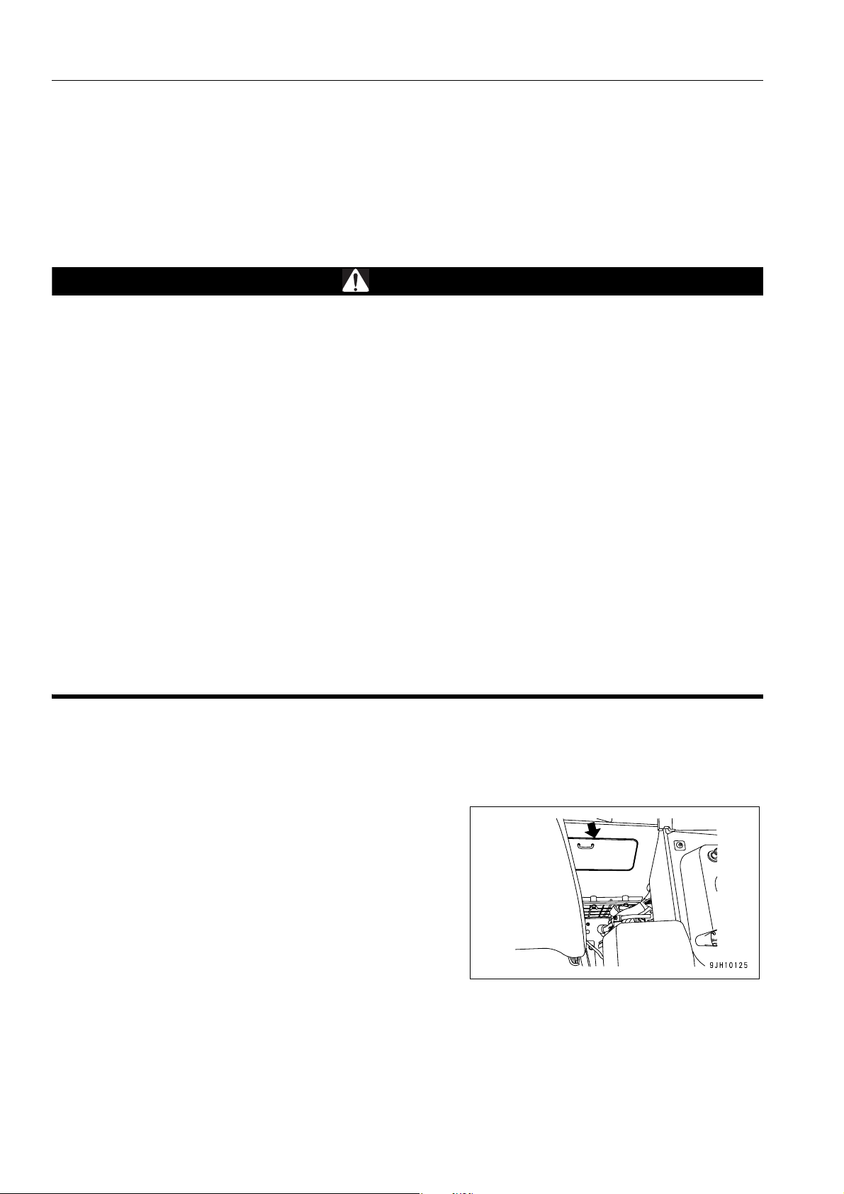
Location to Keep Operation & Maintenance Manual
Operation and Maintenance Manual pocket at the rear of the
operator's seat
1-2
Page 5

FOREWORD SAFETY INFORMATION
SAFETY INFORMATION 1
To enable you to use this machine safely, safety precautions and labels are given in this manual and affixed to the
machine to give explanations of situations involving potential hazards and of the methods of avoiding such situations.
Signal words
The following signal words are used to inform you that there is a potential hazardous situation that may lead to personal injury or damage.
In this manual and on machine labels, the following signal words are used to express the potential level of hazard.
DANGER
WARNING
CAUTION
Example of safety message using signal word
Indicates an imminently hazardous situation which, if not avoided, will result in death or
serious injury.
Indicates a potentially hazardous situation which, if not avoided, could result in death or
serious injury.
Indicates a potentially hazardous situation which, if not avoided, may result in minor or
moderate injury. This word is used also to alert against unsafe practices that may
cause property damage.
WARNING
When standing up from the operator's seat, always place
the lock lever in the LOCK position.
If you accidentally touch the control lev ers when they are
not locked, this may cause a serious injury or death.
Other signal words
In addition to the above, the following signal words are used to indicate precaution s that shou ld be followed to protect the machine or to give information that is useful to know.
NOTICE
REMARKS
This word is used for precautions that must be taken to avoid actions which could shorten
the life of the machine.
This word is used for information that is useful to know.
1-3
Page 6
SAFETY INFORMATION FOREWORD
q Safety labels
Safety labels are affixed to the machine to inform the operator or maintenance worker on the spot when carrying
out operation or maintenance of the machine that may involve hazard.
This machine uses “Safety labels using words“ and “Safety labels using pictograms“ to indicate safety pr ocedur es.
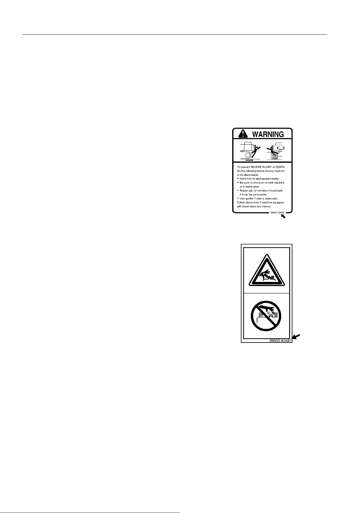
Example of safety label using words
Safety labels using pictogram
Part No.
Safety pictograms use a picture to expre ss a level of hazardous condition equivalent to the signal word. These safety pictograms use pictures in order to let the operator or maintenance
worker understand the level and type of h azardous condition at
all times. Safety pictograms show the type of hazardous condition at the top or left side, and the me thod of avoiding the hazardous condition at the bottom or right side. In addition, the
type of hazardous condition is displayed inside a triangle and
the method of avoiding the hazardous condition is shown
inside a circle.
Part No.
Komatsu cannot predict every circumstance that might involve a potential hazard in operation and maintena nce.
Therefore, the safety messages in this manual and on the machine may not include all po ssible safety precautions.
If any procedures or actions not specifically recommended or allowed in this manual are used, it is your responsibility to take the necessary steps to ensure safety.
In no event should you engage in prohibited uses or actions described in this manual.
The explanations, values, and illustrations in this manual were prepared based on the latest information available
at that time. Continuing improvements in the design of this machine can lead to changes in detail which may not
be reflected in this manual. Consult Komatsu or your Komatsu distributor for the latest available information of
your machine or for questions regarding information in this manual.
The numbers in circles in the illustrations corres pond to the numbers in ( ) in the text. (For example: 1 -> (1))
1-4
Page 7
FOREWORD SAFETY INFORMATION
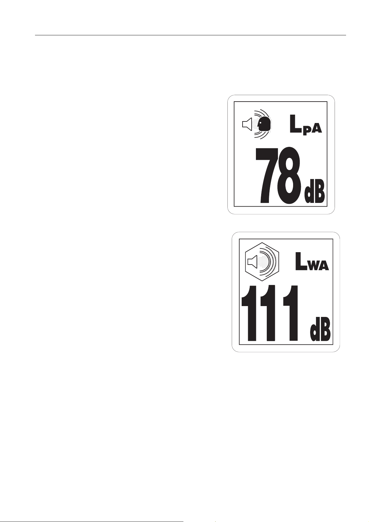
Noise emission levels 1
Two labels ind icating the machine noise level a re affixed on the
machine.
q Sound pressure level at the operator’s station, measured
according to ISO6396 (Dynamic test method, simulated
working cycle).
q Sound power level emitted by the machine, measured
according to ISO 6395 (Dynamic test method, simulated
working cycle). This is the guaranteed value as specified
in European directive 2000/14/EC.
Vibration levels 1
When used for its intended purpose, levels of vibration for the earth-moving machine transmitted from the operator’s seat are lower than or equal to the tested vibrations for the relative machinery class in compliance with ISO
7096.
q If equipped with air suspension seat
The actual acceleration value for the hands and arms is less than or equal to 2.5 m/s². The actual acceleratio n
value for the body is less than or equal to 0.5 m/s².
q If equipped with mechanical suspension seat
The actual acceleration value for the hands and arms is less than or equal to 2.5 m/s².
The actual acceleration value for the body is 0.52 m/s².
1-5
Page 8

SAFETY INFORMATION FOREWORD
These values were determined using a representative machine and measured during the typical operating condition indicated below according to the measurement procedures that are defined in the standards ISO 2631/1 and
ISO 5349.
Operating condition:
(TRACTOR DOZER:) Dozing and spreading material through
forward/reversing motion
Guide to Reduce Vibration Levels on Machine 1
The following guides can help an operator of this machine to
reduce the whole body vibration levels:
1. Use the correct equipment and attachments.
2. Maintain the machine according to this manual
q Tire pressures (for wheeled machines), tension of
crawler (for crawler machines)
q Brake and steering systems
q Controls, hydraulic system and linkages
3. Keep the terrain where the machine is working and traveling in good condition
q Remove any large rocks or obstacles
q Fill any ditches and holes
q Site manager should provide machine operators with
machine and schedule time to maintain terrain conditions
4. Use a seat that meets ISO 7096 and keep the seat maintained and adjusted
q Adjust the seat and suspension for the weight and size
of the operator
q Wear seat belt
q Inspect and maintain the seat suspension and adjust-
ment mechanisms
5. Steer, brake, accelerate, shift gears (for wheeled
machines), and move the attachment levers and pedals
slowly so that the machine moves smoothly
1-6
Page 9

FOREWORD SAFETY INFORMATION
6. Adjust the machine speed and travel path to minimize the
vibration level
q When pushing with bucket or blade, avoid sudden
loading; load gradually
q Drive around obstacles and rough terrain conditions
q Slow down when it is necessary to go over roug h ter-
rain
q Make the curve radius of traveling path as large as
possible
q Travel at low speed when traveling around sharp
curves
7. Minimize vibrations for long work cycle or long distance
traveling
q Reduce speed to prevent bounce
q Transport machines long distances between worksites
8. The following guidelines can be effective to m inimize risks
of low back pain
q Operate the machine only when you are in good
health.
q Provide breaks to reduce long periods of sitting in the
same posture
q Do not jump down from the cab or machine
q Do not repeatedly handle and lift loads
1-7
Page 10
INTRODUCTION FOREWORD
INTRODUCTION 1
This Komatsu machine is designed to be used mainly for the following work:
q Dozing
q Cutting into hard or frozen ground or ditching
q Felling trees, removing stumps
q Pushing
q Ripping
For further details, see “WORK POSSIBLE USING BULLDOZER (3-127)“ and “RIPPER OPERATION (3-120)“.
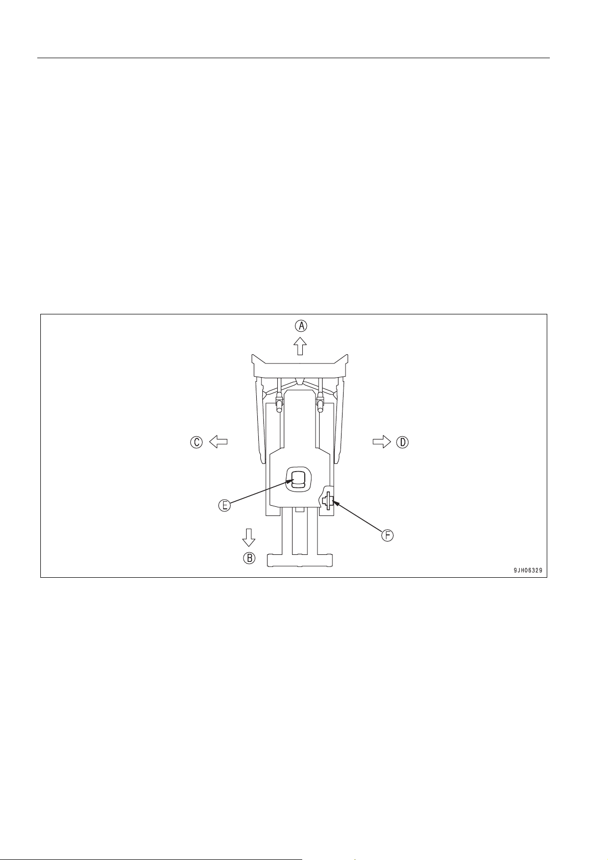
FRONT/REAR, LEFT/RIGHT DIRECTIONS OF MACHINE 1
(A) Front (E) Operator's seat
(B) Rear (F) Sprocket
(C) Left
(D) Right
In this manual, the terms front, rear, left, and right refer to the travel direction as seen from the operator's seat
when the operator's seat is facing the front and the sprocket is at the rear of the machine.
1-8
Page 11
FOREWORD INTRODUCTION
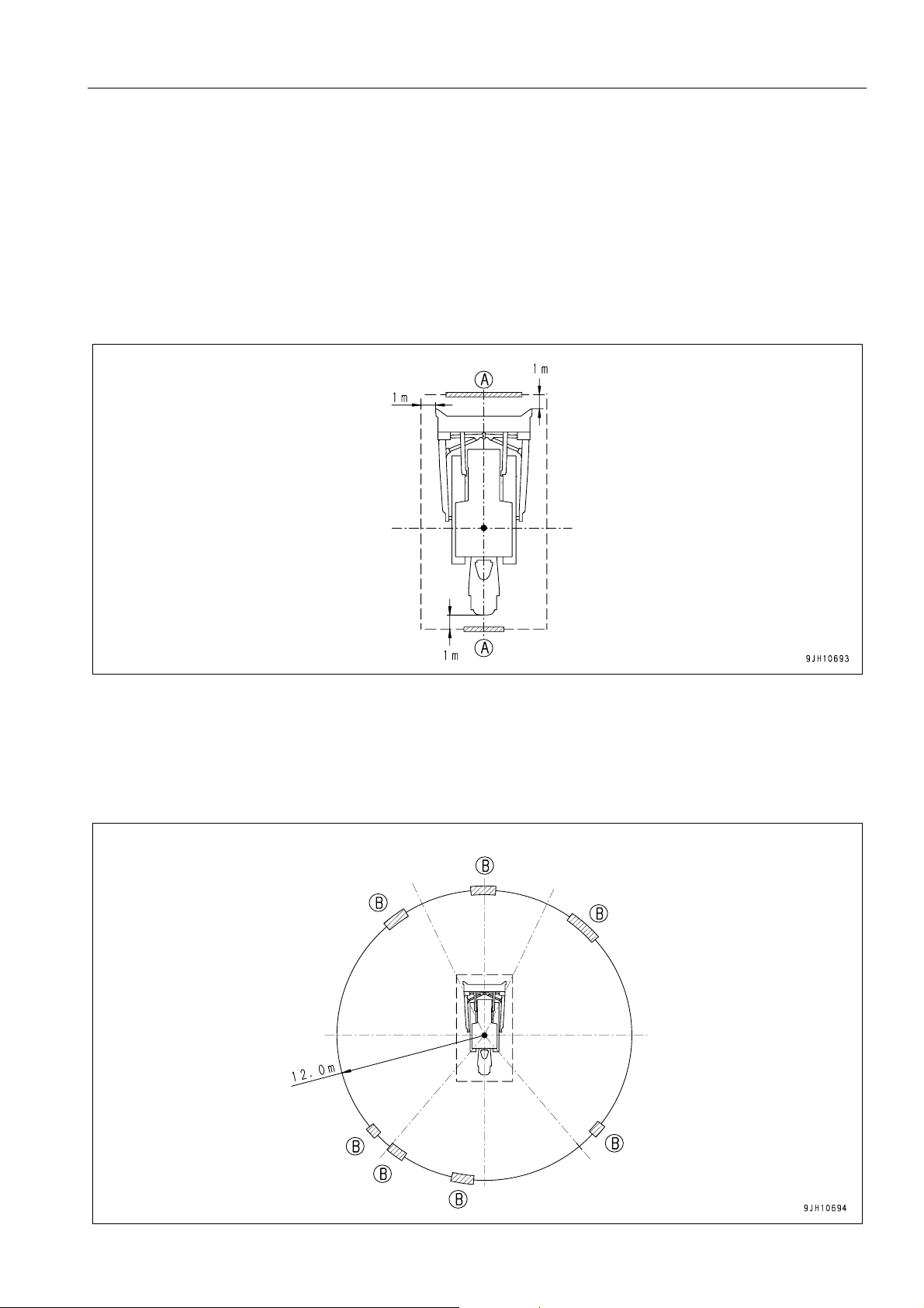
VISIBILITY FROM OPERATOR'S SEAT 1
The visibility standards (ISO 5006) for this machine require a view shown in the diagram below.
PROXIMITY VISIBILITY 1
The visibility of this machine in the area 1 m from the outside surface of the machine at a height of 1.5 m is shown
in the diagram below. The hatched area (A) shows the area where the view is blocked by part of the machine when
mirrors or other aids to visibility are installed as standard. Please be fully aware that there are places that cannot
be seen when operating the machine.
12M CIRCUMFERENCE VISIBILITY 1
The visibility at a radius of 12 m from the machine is as shown in the diagram below. The hatched areas (B) show
the areas where the view is blocked when mirrors or other aids to visibility are installed as standard. Please be
fully aware that there are places that cannot be seen when operating the machine.
1-9
Page 12

INTRODUCTION FOREWORD
BREAKING IN THE MACHINE 1
NOTICE
Your Komatsu machine has been thoroughly adjusted and tested before shipment from the factory. However, ope rating the machine under full load before bre aking the machine in can adverse ly affect the perf ormance and shorten the machine life.
Be sure to break in the machine for the initial 100 hours (as indicated on the service meter).
Make sure that you fully understand the content of this manual, and pay careful attention to the following points
when breaking in the machine.
q Run the engine at idle for 15 seconds after star ting it. During this time, do not oper ate the control levers or fuel
control dial.
q Idle the engine for 5 minutes after starting it up.
q Avoid operation with heavy loads or at high speeds.
q Immediately after starting the engine, avoid sudden starts, sudden acceleration, unnecessary sudden stops,
and sudden changes in direction.
1-10
Page 13
FOREWORD NECESSARY INFORMATION
NECESSARY INFORMATION 1
When requesting service or ordering replacement parts, please inform your Komatsu distributor of the following
items.
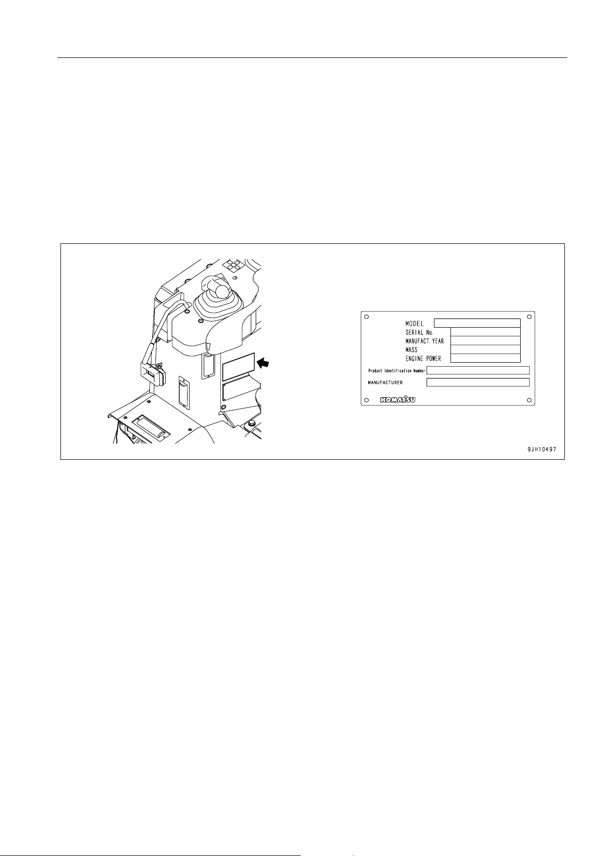
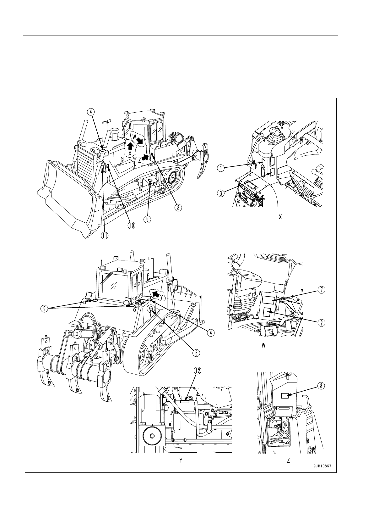
PRODUCT IDENTIFICATION NUMBER (PIN), MACHINE SERIAL NO. PLATE 1
Under the front of the console box on the right side of the operator's seat.
The design of the nameplate differs according to the territory.
1-11
Page 14
NECESSARY INFORMATION FOREWORD
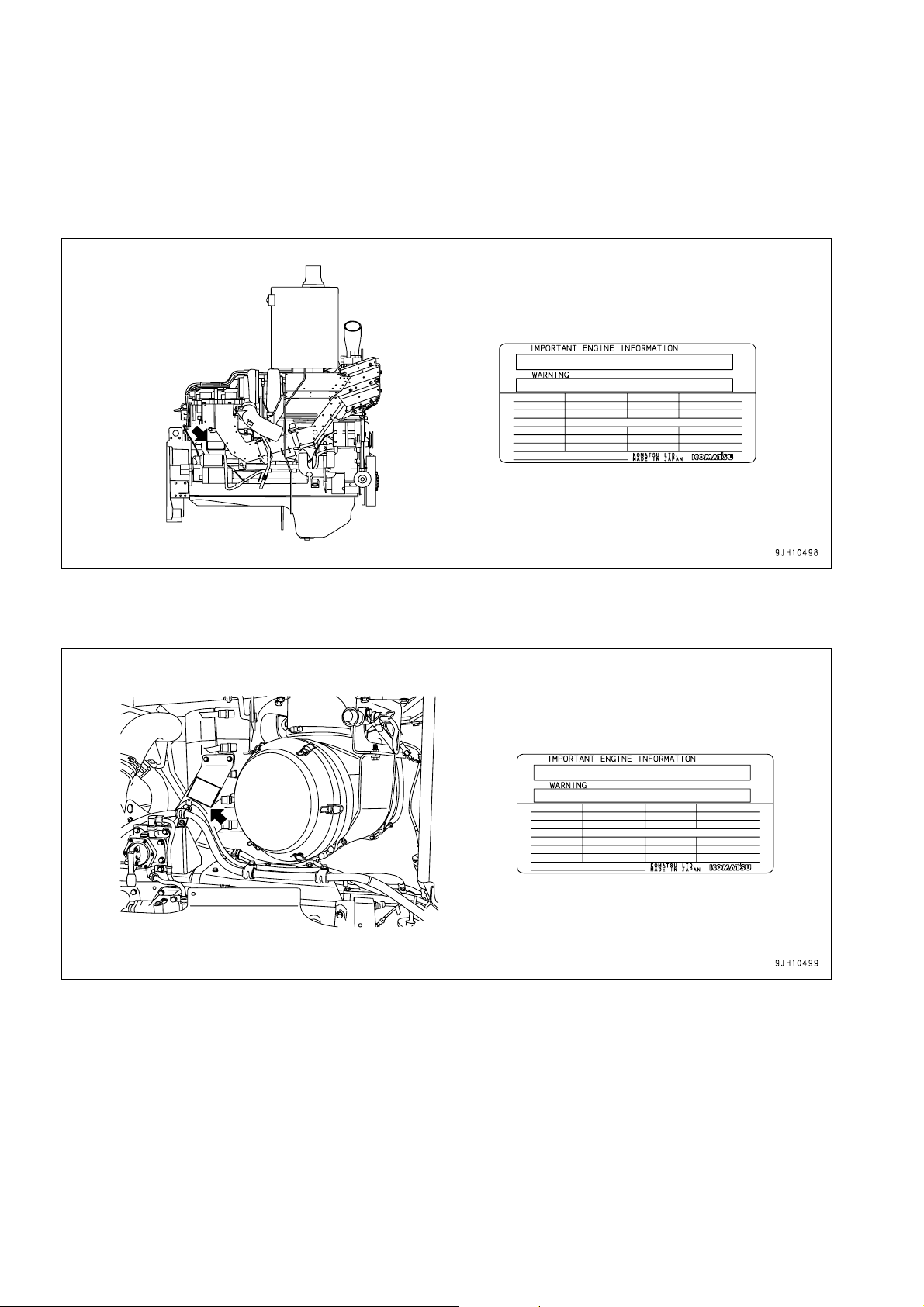
EPA REGULATIONS, EN GINE NUMBER PLATE 1
q On the upper of the engine starting motor on the right side of the machine.
q This also acts as the EPA plate.
q This is on the top surface of the muffler mounting bracket on the left side of the machine.
q This also acts as the EPA plate.
EPA: Environmental Protection Agency, U.S.A.
1-12
Page 15
FOREWORD NECESSARY INFORMATION
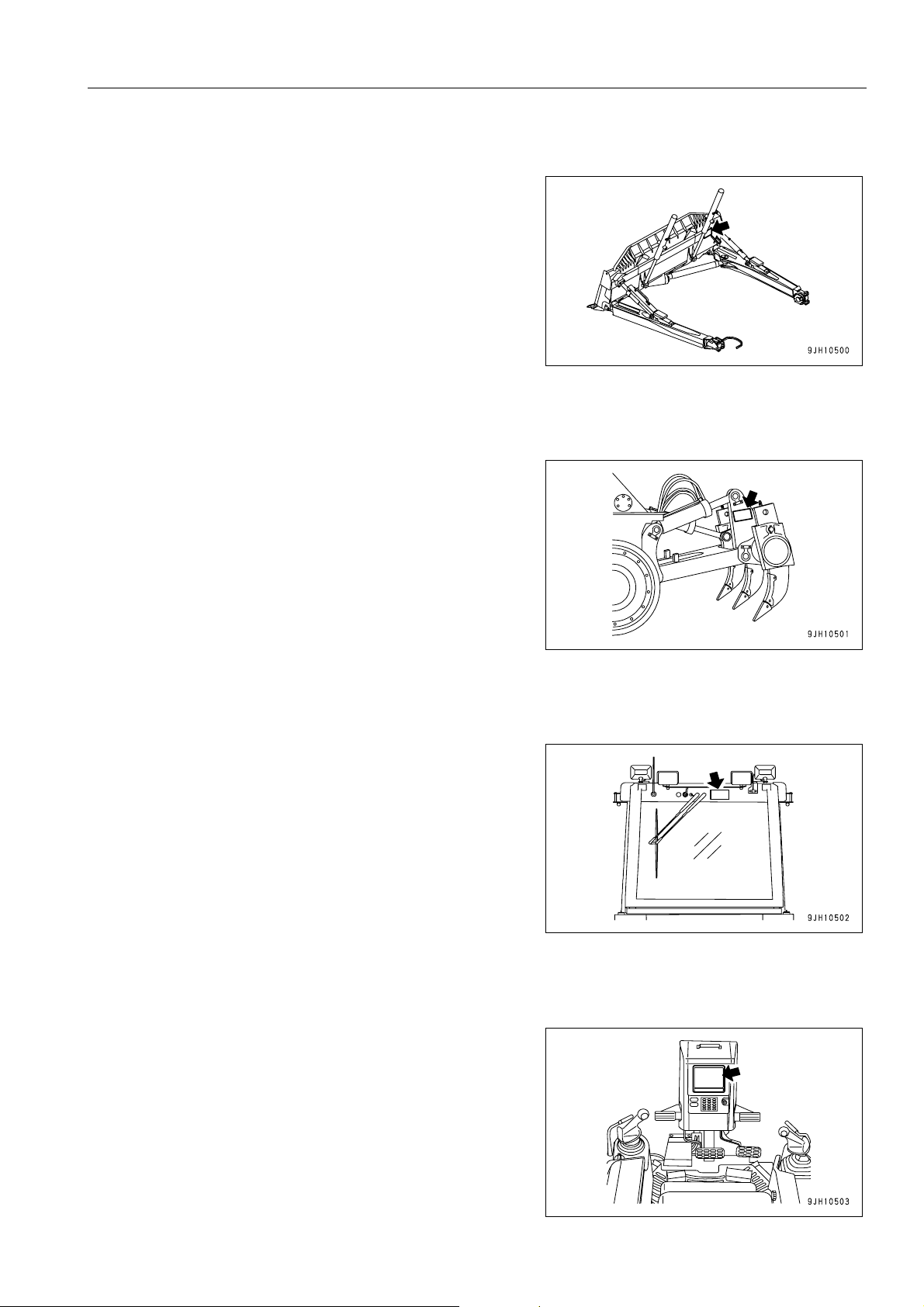
BLADE SERIAL NO. PLATE POSITION 1
This is located on the upper right of blade back surface.
RIPPER SERIAL NO. PLATE POSITION 1
This is located on the left side surface of ripper beam.
ROPS, FOPS NO. PLATE POSITION 1
This is at the top rear of the cab.
POSITION OF SERVICE METER 1
On top of the machine monitor
1-13
Page 16

NECESSARY INFORMATION FOREWORD
TABLE TO ENTER SERIAL NO. AND DISTRIBUTOR 1
Machine serial No.
Engine serial No.
Product Identification Number
Manufacturers name:
Address:
Distributor
Address
Phone
Service personnel for your
machine:
KOMATSU LTD.
3-6 Akasaka
Minato-ku, 101 Tokyo
Japan
1-14
Page 17
FOREWORD NECESSARY INFORMATION
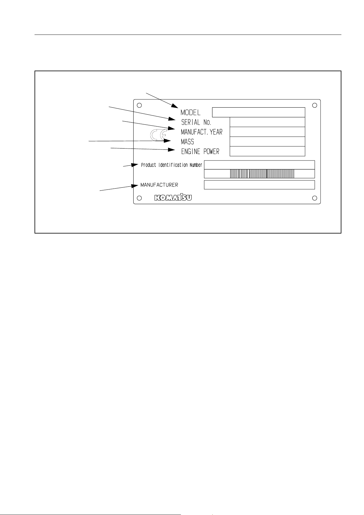
MACHINE SERIAL NUMBER PLATE
Model
Seriel Number
Manufacturing year
Weight
Engine power
Product Identification Number
Manuafacturer
1-15
Page 18

NECESSARY INFORMATION FOREWORD
1-16
Page 19

CONTENTS
CONTENTS
FOREWORD
FOREWORD......................................................................................................................................................... 1-2
SAFETY INFORMATION...................................................................................................................................... 1-3
Noise emission levels ................................................................................................................................. 1-5
Vibration levels................................ ... ... .... ... ... ....................................... ... ... ... .... ... ... ... ............................... 1-5
Guide to Reduce Vibration Levels on Machine.................................................................................. 1-6
INTRODUCTION................................................................................................................................................... 1-8
FRONT/REAR, LEFT/RIGHT DIRECTIONS OF MACHINE........... .... ... .......................................... ... ... ... .. 1-8
VISIBILITY FROM OPERATOR'S SEAT.................................................................................................... 1-9
PROXIMITY VISIBILITY.................................................................................................................... 1-9
12M CIRCUMFERENCE VISIBILITY .......... .... .......................................... ... ... ... .... ... ... ... ... .... ... ........ 1-9
BREAKING IN THE MACHINE.................................................................................................................1-10
NECESSARY INFORMATION ........................................................................................................................... 1-11
PRODUCT IDENTIFICATION NUMBER (PIN), MACHINE SERIAL NO. PLATE .................................... 1-11
EPA REGULATIONS, ENGINE NUMBER PLATE................................................................................... 1-12
BLADE SERIAL NO. PLATE POSITION .............. .... ... ... ... .... ... ... ... .... ... ... ... .......................................... ... 1-13
RIPPER SERIAL NO. PLATE POSITION................................................................................................. 1-13
ROPS, FOPS NO. PLATE POSITION...................................................................................................... 1-13
POSITION OF SERVICE METER ............................................................................................................ 1-13
TABLE TO ENTER SERIAL NO. AND DISTRIBUTOR ............................................................................ 1-14
MACHINE SERIAL NUMBER PLATE....................................................................................................... 1-15
SAFETY
SAFETY................................................................................................................................................................ 2-2
SAFETY LABELS................................................................................................................................................. 2-4
POSITIONS OF SAFETY PICTOGRAMS ....................................................................... ... ... ... ... .... ... ... ... ..2-4
SAFETY LABELS ....................................................................................................................................... 2-5
GENERAL PRECAUTIONS ................................................................................................................................. 2-9
PRECAUTIONS FOR OPERATION................................................................................................................... 2-18
BEFORE STARTING ENGINE ................................................................................................................. 2-18
OPERATION............................................................................................................................................. 2-19
TRANSPORTATION................................................................................................................................. 2-23
BATTERY ................................................................................................................................................. 2-24
TOWING................................................................................................................................................... 2-26
PRECAUTIONS FOR MAINTENANCE.............................................................................................................. 2-27
1-17
Page 20

CONTENTS
OPERATION
GENERAL VIEW .................................................................................................................................................. 3-2
GENERAL VIEW OF MACHINE................................................................................................................. 3-2
GENERAL VIEW OF CONTROLS AND GAUGES..................................................................................... 3-3
EXPLANATION OF COMPONENTS....................................................................................................................3-5
MACHINE MONITOR .................................................................................................................................3-5
BASIC OPERATION OF MACHINE MONITOR ................................................................................ 3-6
BASIC CHECK MONITORS..............................................................................................................3-9
CAUTION MONITORS ................. ... ... .... ... ... ... ....................................... ... ... .... ... ... ... .... ... ...............3-10
EMERGENCY MONITORS .......... ... ... ....................................... ... .... ... ... ... ...................................... 3-12
METER DISPLAY PORTION...........................................................................................................3-14
MONITOR SWITCHES PORTION ............................ ... ... .......................................... .... ... ... ............3-21
HANDLING FUNCTION SWITCHES......................... ... ... .... ... ... ... .... ... ... ... ... .... ... ... ... .... ..................3-26
SPEED RANGE DISPLAY............................................................................................................... 3-48
SWITCHES............................................................................................................................................... 3-49
CONTROL LEVERS, PEDALS.................................................................................................................3-53
DUST INDICATOR ................................................................................................................................... 3-61
FUSE BOX................................................................................................................................................3-61
CIRCUIT BREAKER........................................................................................................................3-63
CIRCUIT BREAKER FOR MAIN POWER SUPPLY........................................................................ 3-63
FUSE CAPACITY AND NAME OF CIRCUIT................................................................................... 3-64
DOOR POCKET .......................................................................................................................................3-65
ASHTRAY................................................................................................................................................. 3-65
HANDLING AIR CONDITIONER .............................................................................................................. 3-66
GENERAL LOCATIONS OF CONTROL PANEL ............................................................................ 3-66
METHOD OF OPERATION............................................. .... ... ... ... .... ... ...................................... .... ..3-70
PRECAUTIONS WHEN USING AIR CONDITIONER ..................................................................... 3-76
INSPECTION AND MAINTENANCE OF AIR CONDITIONER EQUIPPED MACHINE................... 3-77
OPERATION.......................................................................................................................................................3-78
CHECK BEFORE STARTING ENGINE, ADJUST................................. .... ... ... ... ... .... ... ... ... .... ... ... ... ... .... .. 3-78
WALK-AROUND CHECK ................................................................................................................3-78
CHECK BEFORE STARTING .........................................................................................................3-79
ADJUSTMENT.................................................................................................................................3-89
OPERATIONS AND CHECKS BEFORE STARTING ENGINE....................................................... 3-93
STARTING ENGINE................................................................................................................................. 3-95
NORMAL STARTING ................ ...................................... .... ... ... ... ....................................... ... ......... 3-95
STARTING IN COLD WEATHER.................................................................................................... 3-97
OPERATIONS AND CHECKS AFTER STARTING ENGINE.................................................................3-100
WARMING UP OPERATIONS .................................. ... ... .... ... ... ... .... ... .......................................... 3-100
IN COLD AREAS.......................................................... ... .... ... ... ... .... ... ... ... ... .................................3-101
STOPPING ENGINE . ... ... ... ....................................... ... .... ... ... ....................................... ... ... .... ................3-102
MOVING MACHINE................................................................................................................................ 3-103
STOPPING MACHINE. ....................................... ... ... ... .... ... ....................................... ... ... ... .... ................ 3-105
SHIFTING GEAR.................................................................................................................................... 3-106
SHIFTING BETWEEN FORWARD AND REVERSE ..............................................................................3-112
1-18
Page 21

CONTENTS
STEERING MACHINE............................................................................................................................ 3-114
NORMAL TURNING...................................................................................................................... 3-114
TURNING WHILE DESCENDING A SLOPE................................................................................. 3-115
PRECAUTIONS FOR OPERATION.................................. .... ... ... ... .... ... ... ... ... .... ... ... .............................. 3-116
PAY ATTENTION TO GAUGES.................................................................................................... 3-116
PERMISSIBLE WATER DEPTH...................... ... ... ... .... ... ... ... .... ... ... ... ... .... ... ... ... ........................... 3-116
PRECAUTIONS WHEN TRAVELING UP OR DOWN HILLS........................................................ 3-116
PRECAUTIONS ON SLOPE ......................................................................................................... 3-116
METHOD OF USING BRAKES ..................................................................................................... 3-117
PROHIBITED TO KEEP THE DOOR OPEN DURING OPERATIONS......................................... 3-117
IT IS PROHIBITED TO MODIFY THE CAB GLASS IN ANY WAY THAT WILL OBSTRUCT THE VIEW
3-117
PARKING MACHINE.............................................................................................................................. 3-118
CHECK AFTER STOPPING ENGINE .................................................................................................... 3-119
CHECK AFTER FINISHING WORK ....................................................................................................... 3-120
LOCKING................................................................................................................................................ 3-120
RIPPER OPERATION ............................................................................................................................ 3-120
EFFECTIVE METHOD OF USE.................................................................................................... 3-120
DIGGING UP BOULDERS OR ROCKBED ................................................................................... 3-121
OPERATING ON SLOPES............................................................................................................ 3-121
METHOD OF OPERATING PIN PULLER..................................................................................... 3-122
OPERATING METHOD FOR RIPPING OPERATIONS ........................... ... ... .... ... ... ... .... ... ... ... ... .... ... ... . 3-123
BASIC OPERATING METHOD....................................... ... ... .... ... ... ... ... .... ... ... ... .... ... ... ... ... .... ....... 3-123
RIPPING BY CLIFFS................................... .... ... ... ... ..................................................................... 3-124
RIPPING BY SLOPE FACES........................................................................................................ 3-124
DIGGING UP BOULDERS .... ... ... .... ... ... ... ... .... ... ....................................... ... ... ... .... ... ... ... ... ........... 3-125
PRECAUTIONS WHEN RIPPING................................................................................................. 3-126
WORK POSSIBLE USING BULLDOZER............................................................................................... 3-127
DOZING......................................................................................................................................... 3-127
SMOOTHING................................................................................................................................. 3-128
CUTTING INTO HARD OR FROZEN GROUND OR DITCHING.................................................. 3-128
FELLING TREES, REMOVING STUMPS..................................................................................... 3-128
PUSHER OPERATIONS.......................................... .... ...................................... .... ... ... ... ... .... ... .... 3-129
ADJUSTING POSTURE OF WORK EQUIPMENT................................................................................. 3-129
BLADE ADJUSTMENT.................................................................................................................. 3-129
METHOD OF ANGLING BLADE................................................................................................... 3-131
ADJUSTING TILT AMOUNT . ... ... ....................................... ... .... ... ... ... ....................................... ... . 3-132
ADJUSTING RIPPER...................................................................... ... ... .... ... ... .............................. 3-134
ADJUST ANGLE OF BLADE EDGE.............................................................................................. 3-135
TIPS FOR LONGER UNDERCARRIAGE LIFE........................................................................ ... .... ... ... . 3-136
OPERATION METHOD................................................................................................................. 3-136
INSPECTION AND ADJUSTING................................................................................................... 3-137
INSPECTION AND REPAIR ..........................................................................................................
3-137
TRANSPORTATION......................................................................................................................................... 3-139
LOADING, UNLOADING WORK.................................... ... .... ... ... ... .... ... ... ... ... .... .................................... 3-139
LOADING....................................................................................................................................... 3-139
SECURING MACHINE..................................................................................................................3-140
1-19
Page 22

CONTENTS
UNLOADING .................................................................................................................................3-141
METHOD OF LIFTING MACHINE..........................................................................................................3-142
PRECAUTIONS FOR TRANSPORTATION ...........................................................................................3-144
TRAVELING ON ROADS .......................................................................................................................3-144
REMOVAL OF CAB................................................................................................................................ 3-145
COLD WEATHER OPERATION ......................................................................................................................3-147
PRECAUTIONS FOR LOW TEMPERATURE ........................................................................................ 3-147
FUEL AND LUBRICANTS ............... ... .... ... ... ... ... ....................................... ... .... ... ... .......................3-147
COOLANT .....................................................................................................................................3-147
BATTERY ...................................................................................................................................... 3-148
AFTER COMPLETION OF WORK ........... ... .... ... ... ... ... .... ... ... ... ....................................... ... .... ... ... ... ... .... 3-149
AFTER COLD WEATHER ..................... ... ... .... ... ....................................... ... ... ... ... .... ... ... ... ....................3-149
LONG-TERM STORAGE..................................................................................................................................3-150
BEFORE STORAGE . ... ... ... .... ...................................... .... ... ... ... ....................................... ... .... ................3-150
DURING STORAGE ................. ... ... .... ... ... ... .... ...................................... .... ... ... ... .................................... 3-150
AFTER STORAGE.... ... ... ... .... ... ....................................... ... ... ... .... ... ... ... .... ............................................. 3-150
TROUBLESHOOTING...................................................................................................................................... 3-151
AFTER RUNNING OUT OF FUEL.......................................................................................................... 3-151
PROCEDURE FOR BLEEDING AIR.............................................................................................3-151
METHOD OF TOWING MACHINE.........................................................................................................3-153
IF BATTERY IS DISCHARGED.............................................................................................................. 3-154
REMOVAL AND INSTALLATION OF BATTERY .......................................................................... 3-154
PRECAUTIONS WHEN CHARGING BATTERY...........................................................................3-155
STARTING ENGINE WITH BOOSTER CABLE ............................................................................ 3-155
OTHER TROUBLE ................................... ... .... ... ....................................... ... ... ... ... .... .............................3-158
ELECTRICAL SYSTEM.................................................................................................................3-158
ELECTRONIC CONTROL SYSTEM ...... ... ... ... ... .... ... ... ... .... ... ... ... .................................................3-159
CHASSIS.......................................................................................................................................3-160
ENGINE......................................................................................................................................... 3-161
POINT OF CONTACT TO TELEPHONE WHEN ERROR OCCURS............................................ 3-162
MAINTENANCE
GUIDES TO MAINTENANCE...............................................................................................................................4-2
OUTLINES OF SERVICE .....................................................................................................................................4-5
HANDLING OIL, FUEL, COOLANT, AND PERFORMING OIL CLINIC......................................................4-5
OIL.....................................................................................................................................................4-5
FUEL..................................................................................................................................................4-6
COOLANT AND WATER FOR DILUTION.........................................................................................4-6
GREASE............................................................................................................................................ 4-7
CARRYING OUT KOWA (Komatsu Oil Wear Analysis) .................................................................... 4-7
STORING OIL AND FUEL..... .... ... ....................................... ... ... ... .... ...................................... ... ........ 4-8
FILTERS............................................................................................................................................4-8
OUTLINE OF ELECTRIC SYSTEM............................................................................................................ 4-8
1-20
Page 23

CONTENTS
WEAR PARTS LIST........................................................................................................................................... 4-10
WEAR PARTS LIST.................................................................................................................................. 4-10
RECOMMENDED FUEL, COOLANT, AND LUBRICANT ................................................................................. 4-12
RECOMMENDED BRANDS, RECOMMENDED QUALITY FOR PRODUCTS OTHER THAN KOMATSU
GENUINE OIL........................................................................................................................................... 4-14
STANDARD TIGHTENING TORQUES FOR BOLTS AND NUTS..................................................................... 4-15
TORQUE LIST.......................................................................................................................................... 4-15
PERIODIC REPLACEMENT OF SAFETY CRITICAL PARTS .......................................................................... 4-16
SAFETY CRITICAL PARTS...................................................................................................................... 4-16
MAINTENANCE SCHEDULE CHART ............................................................................................................... 4-18
MAINTENANCE SCHEDULE CHART......................................................................................................4-18
INITIAL 250 HOURS SERVICE (ONLY AFTER THE FIRST 250 HOURS) .................................... 4-18
WHEN REQUIRED.......................... ...................................... .... ... ... ... ............................................. 4-18
CHECK BEFORE STARTING......................................... ... ... .... ... ... ... ... .... ...................................... 4-18
EVERY 250 HOURS SERVICE....................................................................................................... 4-18
EVERY 500 HOURS SERVICE....................................................................................................... 4-18
EVERY 1000 HOURS SERVICE..................................................................................................... 4-19
EVERY 2000 HOURS SERVICE..................................................................................................... 4-19
EVERY 4000 HOURS SERVICE..................................................................................................... 4-19
EVERY 8000 HOURS SERVICE..................................................................................................... 4-19
SERVICE PROCEDURE .................................................................................................................................... 4-20
INITIAL 250 HOURS SERVICE (ONLY AFTER THE FIRST 250 HOURS) ............................................. 4-20
WHEN REQUIRED................................................................................................................................... 4-20
CHECK BEFORE STARTING .................................................................................................................. 4-39
EVERY 250 HOURS SERVICE................................................................................................................4-40
EVERY 500 HOURS SERVICE................................................................................................................4-48
EVERY 1000 HOURS SERVICE.............................................................................................................. 4-55
EVERY 2000 HOURS SERVICE.............................................................................................................. 4-65
EVERY 4000 HOURS SERVICE.............................................................................................................. 4-72
EVERY 8000 HOURS SERVICE.............................................................................................................. 4-76
SPECIFICATIONS
SPECIFICATIONS................................................................................................................................................ 5-2
ATTACHMENTS, OPTIONS
GENERAL PRECAUTIONS ................................................................................................................................. 6-2
PRECAUTIONS RELATED TO SAFETY ...................................................................................................6-2
INTRODUCTION OF ATTACHMENTS AND OPTIONS ...................................................................................... 6-3
INTRODUCTION OF ATTACHMENTS AND OPTIONS............................................................................. 6-3
1-21
Page 24

CONTENTS
HEADREST, HANDLING .....................................................................................................................................6-4
CAP WITH LOCK, HANDLING ............................................................................................................................ 6-5
METHOD OF OPENING AND CLOSING CAP WITH LOCK................................. .... ... ... ... .... ... ... ... ... .... ... . 6-5
PROCEDURE FOR SELECTING RIPPER POINT...............................................................................................6-6
PROCEDURE FOR SELECTING RIPPER POINT..................................................................................... 6-6
HANDLING MACHINES EQUIPPED WITH KOMTRAX......................................................................................6-7
BASIC PRECAUTIONS .................. .... ... ... ....................................... ... ... .... ... ... ... ... .... ................................. 6-7
INDEX
COLOPHON
1-22
Page 25

SAFETY
12
WARNING
Please be sure that you fully underst an d this manual an d the
precautions discribed in this manual and the safety labels
on the machine. When operating or servicing the machine,
always follow these precaustions strictly.
Page 26

SAFETY SAFETY
SAFETY 2
Safety Labels .. .... ... ... ... .... ...................................... .... ... ... ... ... .... ... ... ...................................................................2-42
Positions of Safety Pictograms ....................................................................................................................2-42
Safety Labels ...............................................................................................................................................2-52
General Precautions
Safety Rules................................................................................................................................................. 2-92
If Abnormalities are Found...........................................................................................................................2-92
Clothing and Personal Protective Items.......................................................................................................2-92
Fire Extinguisher and First Aid Kit................................................................................................................2-92
Safety Features.......................................................................................................................................... 2-102
Keep Machine Clean..................................................................................................................................2-102
Inside Operator's Compartment.................................................................................................................2-102
Always Apply Lock when Leaving Operator's Seat............................. ... ... .... ... ... ... ... .... ... ... ... .... ... ... ... .......2-102
Handrails and Steps..................................... ... .... ... ... ... ... .... ... ....................................... ... ..........................2-112
Mounting and Dismounting ........................................................................................................................ 2-122
No People on Attachments ........................................................................................................................ 2-122
Prevention of Burns.................................................................................................................................... 2-122
Fire Prevention...........................................................................................................................................2-122
Action if Fire Occurs .. ... ... ... ... .... ... ....................................... ... ... ... .... ... ... ... .... ............................................. 2-132
Window Washer Liquid .............................................................................................................................. 2-132
Precautions when Using ROPS ................................................................................................................. 2-142
Precautions for Attachments........ ... ... .... ... ... ... .... ... ... ... .......................................... ... .... ... ..........................2-142
Unauthorized Modification..........................................................................................................................2-142
Safety at Worksite...................................................................................................................................... 2-152
Working on Loose Ground........................................................ .......................................... ... ....................2-152
Do not Go Close to High-Voltage Cables...................................................................................................2-152
Ensure Good Visibility................................................................................................................................2-162
Ventilation for Enclosed Areas...................................................................................................................2-162
Checking Signalman's Signals and Signs.................................................................................................. 2-162
Be Careful About Asbestos Dust................................................................................................................2-172
Precautions for Operation ................................................................................................................................. 2-182
Before Starting Engine...............................................................................................................................2-182
Checks Before Starting Engine...........................................................................................................2-182
Precautions when Starting................................................................. .... ... ... ... ... .... ... ... ... ....................2-182
Precautions in Cold Areas ..................................................................................................................2-192
Operation ...................................................................................................................................................2-192
Checks Before Operation....................................................................................................................2-192
Precautions for Moving Machine Forward or in Reverse....................................................................2-202
Precautions when Traveling.................. ... .... ... ... ... ... .... ... ... ... .... ... .......................................................2-202
Traveling on Slopes ............................................................................................................................2-212
Prohibited Operations .........................................................................................................................2-212
Using Brakes...................... ... ....................................... ... ... ... .... ... ... ... .... ............................................. 2-212
Operate Carefully on Snow.................................................................................................................2-222
Parking Machine.......................................... ... ... ... ....................................... ... ... .... ... ... .......................2-222
Transportation............................................................................................................................................ 2-232
Shipping.............................................................................................................................................. 2-232
Battery........................................................................................................................................................ 2-242
Battery Hazard Prevention.............................. ... ... ... .... ... ... ... .... ..........................................................2-242
Starting with Booster Cable ................................................................................................................ 2-252
Towing........................................................................................................................................................2-262
When Towing...................................................................................................................................... 2-262
2-2
Page 27

SAFETY SAFETY
Precautions for Maintenance ....................... ... .... ... ... ... ... .... ... ... ... .......................................... ........................... 2-272
Warning Tag .............................................................................................................................................. 2-272
Keep Work Place Clean and Tidy... ... ... ... .... ... .......................................... ... ... ........................................... 2-272
Appoint Leader when Working with Others.................. ... ... ... .... ... ... ... .... ... ................................................. 2-272
Stop Engine Before Carrying Out Inspection and Maintenance ................................................................2-282
Two Workers for Maintenance when Engine is Running ........................................................................... 2-282
Proper Tools ............ ... ... .... ... ... ....................................... ... ... .... ... .............................................................. 2-292
Handling Accumulator................................................................................................................................ 2-292
Personnel...................................................................................................................................................2-292
Attachments............................................................................................................................................... 2-302
Work Under the Machine ........................................................................................................................... 2-302
Noise.......................................................................................................................................................... 2-302
Precautions when Using Hammer ............................................................................................................. 2-302
Repair Welding .......................................................................................................................................... 2-302
Removing Battery Terminal ........ .... ... ... ... .... ... ... ... ... .... ... ... ... .... .......................................... ... .................... 2-312
Precautions when Using High-Pressure Grease to Adjust Track Tension................................................. 2-312
Do not Disassemble Recoil Spring ............................................................................................................ 2-312
Precaution with High-Pressure Oil............................................................................................................. 2-312
Precaution for High Fuel Pressure............................... ... ... ... .... ... ... ... .... .................................................... 2-322
Handing High-Pressure Hoses .................................................................................................................. 2-322
Precaution for High Voltage...................................................................... ... ... ... .... ... ... .............................. 2-322
Waste Material........................................................................................................................................... 2-332
Maintenance for Air Conditioner ................................................................................................................ 2-332
Compressed Air......................................................................................................................................... 2-332
Periodic Replacement of Safety Critical Parts ........................................................................................... 2-332
2-3
Page 28
SAFETY LABELS SAFETY
SAFETY LABELS 2
POSITIONS OF SAFETY PICTOGRAMS 2
2-4
Page 29
SAFETY SAFETY LABELS
SAFETY LABELS 2
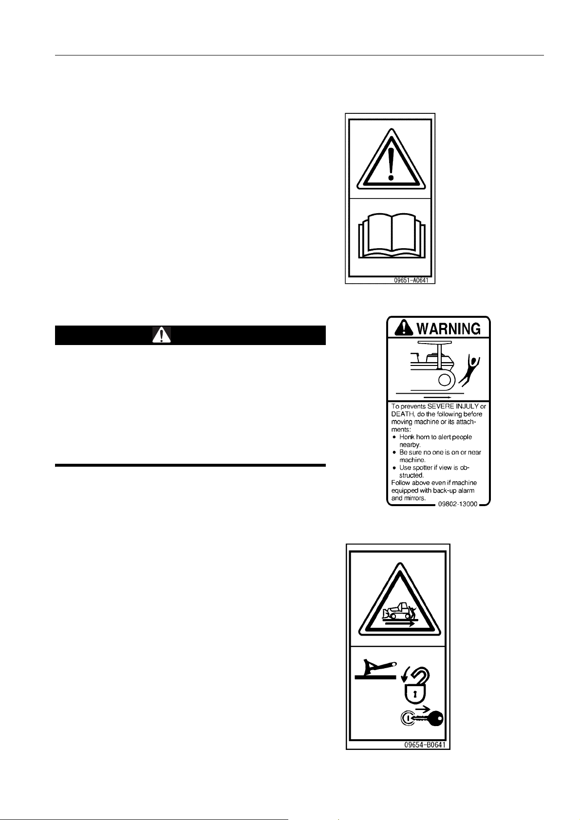
(1) Caution for operation, inspection, and maintenance
(09651-A0641)
q Warning!
q Read manual before operation, maintaince, disassembly,
assembly and transportation.
(2) Caution when traveling in reverse (09802-13000)
WARNING
To prevent SEVERE INJURY or DEATH, do the following
before moving machine or its attachments:
q Honk horn to alert people nearby.
q Be sure no one is on or near the machine.
q Use spotter if view is obstructed.
Follow above even if the machine is equipped with backup alarm and mirrors.
(3) Warning for leaving operator's seat (09654-B0641)
q Sign indicates a hazard of unexpected m oving of stopped
machine.
q Lower working device to ground, move safety lever to lock
position and take engine key with you before leaving
machine.
2-5
Page 30
SAFETY LABELS SAFETY
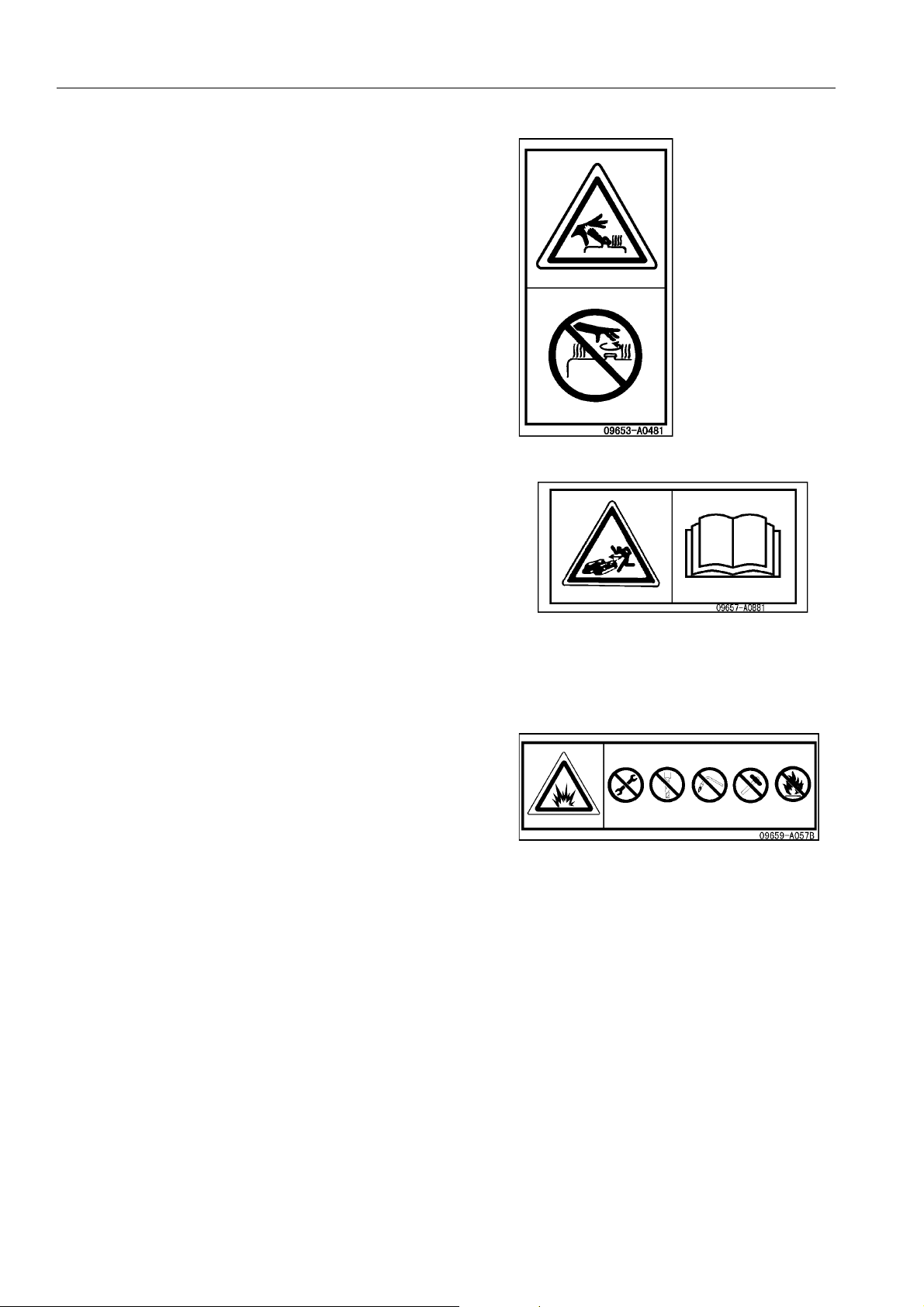
(4) Warning for hot water hazard (09653-A0481)
q Never remove the cap when the engine is at operating
(High) temperature. S t re am or h igh temp er ature oil blowin g
up from the radiator or hydraulic tank, will cause personal
injury and / or burns.
q Never remove the radiator or hydraulic tank oil filler when
cooling water or hydraulic oil is at high temperatures.
(5) Caution when adjusting track tension (09657-A0881)
Safety label is attached to the back side of the inspection cover
of the track frame.
q Sign indicates a hazzard of flying plug from track adjuster
that could cause injury.
q Read the manual and adjusting track for safe and proper
handling.
(6) Caution for handling accumulator (09659-A057B)
q There is the hazard of explotion causing injury.
q Do not disassemble the accumulator, make holes in it, weld
it, cut it, hit it, roll it or bring it near flame.
2-6
Page 31

SAFETY SAFETY LABELS
(7) Caution for use of seat belt (195-98-12940)
q ALWAYS USE SEAT BELT WHEN OPERATING
MACHINE.
q ALWAYS CHECK CONDITION OF THE SEAT BELT, THE
CONNECTING BRACKETS AND THE TIGHTENING
BOLTS.
q ADJUST SEA T TO ALLOW FULL BREAK PEDAL TRAVEL
WITH OPERATOR’S BACK AGAINST SEAT BACK.
q AFTER ADJUSTING THE HEIGHT, FORE AND AFT
POSITION OF THE SEAT, TIGHTEN THE TETHER BELT
BEFORE SITTING IN THE SEAT.
(8) Caution when handling cable (09808-A0881)
q There is the hazard to electric shock when handling electri c
wires.
q Read the operation and maintenance manual and carrying
out the correct method when handling.
(9) Caution against falling (09805-C0881)
q Sign indicates a hazard of falling.
q Do not stand on this place here.
2-7
Page 32

SAFETY LABELS SAFETY
(10) Caution to stop engine when carrying out inspection and
maintenance (09667-A0481)
q Sign indicates a hazard of rotating parts, such as belt.
q Turn off before inspection and maintenance.
(11) Caution about going close when machine is moving
(09806-B1683)
q Sign indicates a hazard of being run over by moving equip-
ment.
q Keep a safe distance from equipment when it is moving.
(12) Prohibition of jump start (09842-A0481)
q Start the engine only after sitting down in the operator’s
seat.
q Do not attempt to start the engine by short-circuiting the
engine starting circuit. Such an act may cause a serious
bodily injury or fire.
2-8
Page 33

SAFETY GENERAL PRECAUTIONS
GENERAL PRECAUTIONS 2
SAFETY RULES
q Only trained and authorized personnel can operate and maintain the machine.
q Follow all safety rules, precautions and instructions when operating or performing maintenance on the
machine.
q If you are under the influence of alcohol or medication, your ability to safely operate or repair your machine
may be severly impaired putting yourself and everyone else on your jobsite in danger.
q When working with another operator or with a person on worksite traffic duty, b e sure tha t all per sonn el u nder-
stand all hand signals that are to be used.
IF ABNORMALITIES ARE FOUND
If you find any problems in the machine during operation o r mainten ance (noise, vibration, smell, in correct gauges,
smoke, oil leakage, etc., or any abnormal display on the warning devices or monitor), report to the person in
charge and have the necessary action taken. Do not operate the machine until the problem has been corrected.
CLOTHING AND PERSONAL PROTECTIVE ITEMS
q Do not wear loose clothing and accessories. There is a hazard that they may catch on control levers or other
protruding parts.
q If you have long hair and it hangs out from your hard hat,
there is a hazard that it may get caught up in the machine,
so tie your hair up and be careful not to let it get caught.
q Always wear a hard hat and safety sh oes. If the nature of
the work requires it, wear safety glasses, mask, gloves, ear
plugs, and safety belt when operating or maintaining the
machine.
q Check that all protective equipment functions properly
before using it.
FIRE EXTINGUISHER AND FIRST AID KIT
Always follow the precautions below to prepare for action if any injury or fire should occur.
q Be sure that fire extinguishers have been provided and
read the labels to ensure that you know how to use th em in
emergencies.
q Carry out periodic inspection and maintenance to ensure
that the fire extinguisher can always be used.
q Provide a first aid kit in the storage po int. Carry out peri-
odic checks and add to the contents if necessary.
2-9
Page 34

GENERAL PRECAUTIONS SAFETY
SAFETY FEATURES
q Be sure that all guards and covers are in their pro per position. Have g uards and covers rep aired immedia tely if
they are damaged.
q Understand the method of use of safety features and use them properly.
q Never remove any safety features. Always keep them in good operating condition.
KEEP MACHINE CLEAN
q If water gets into the electrical system, there is a hazard that it will cause malfunctions or misoperation. Do not
use water or steam to wash the electrical system (sensors, connectors).
q If inspection and maintenance is carried out when the
machine is still dirty with mud or oil, there is a hazard that
you will slip and fall, or that dirt or mud will get into your
eyes. Always keep the machine clean.
INSIDE OPERATOR'S COMPARTMENT
q When entering the operator's compartment, always remove all mud and oil from the soles of your shoes.
If you operate the pedal with mud or oil affixed to your shoes, your foot may slip and this may cause a serious
accident.
q Do not leave parts or tools lying around the operator's compartment.
q Do not stick suction pads to the window glass. Suction pads act as a lens and may cause fire.
q Do not use cellular telephones inside the operator's compar tment when driving or operating the machine.
q Never bring any dangerous objects such as flammable or explosive items into the operator 's compartment.
ALWAYS APPLY LOCK WHEN LEAVING OPERATOR'S SEAT
q Before standing up from the operator's seat, such as when
carrying out adjustment of the operator's seat, always
lower the work equipment to the ground, set the work
equipment lock lever and parking brake lever to the LOCK
position, then stop the engine.
If you accidentally touch the levers when they are not
locked, there is a hazard that the machine may suddenly
move and cause serious injury or property da m ag e .
REMARK
The work equipment lock lever and parking brake lever can
both be operated from the side or front of the operator.
2-10
Page 35

SAFETY GENERAL PRECAUTIONS
q When leaving the machine, always lower the work equip-
ment completely to the ground, set work equipment lock
lever and parking lever securely to the LOCK position, then
stop the engine. Use the key to lock all the equipment.
Always remove the key, take it with you, and keep it in the
specified place.
HANDRAILS AND STEPS
To prevent personal injury caused by slipping or falling off the machine, always do as follows.
q Use the parts marked by arrow A in the diagrams when
getting on or off the machine.
Never use the parts marked by arrow B when getting on or
off the machine. Use them only when moving along the top
of the track or when checking or carrying out maintenance
inside the side cover, or when filling the tank with oil.
q Never jump on or off the machine. In particular, never get
on or off a moving machine. This may cause serious injury.
q To ensure safety, always face the machine and maintain
three-point contact (both feet and one hand, or both hands
and one foot) with the handrails and steps (including the
track shoe) to ensure that you support yourself.
q Do not grip the control levers, or work equipment lock lever
when getting on or off the machine.
q Never climb on the engine hood or covers where there are
no non-slip pads.
q Before getting on or off the machine, check the handrails
and steps (including the track shoe). If there is any oil,
grease, or mud on the handrails or steps (including the
track shoe), wipe it off immediately. Always keep these
parts clean. Repair any damage and tighten any loose
bolts.
q Do not get on or off the machine while holding tools in your hand.
2-11
Page 36

GENERAL PRECAUTIONS SAFETY
MOUNTING AND DISMOUNTING
q Never jump on or off the machine. Never get on or off a moving machine.
q If the machine starts to move when ther e is no operator on the machine, d o not jump on to the machine and tr y
to stop it.
NO PEOPLE ON ATTACHMENTS
Never let anyone ride on the work equipment, or other attachments. There is a hazard of falling and suffering serious injury.
PREVENTION OF BURNS
Hot coolant
q To prevent burns from hot water or steam spurting out
when checking or draining the coolant, wait for the water to
cool to a temperature where it is possible to touch the radiator cap by hand before starting the operation. Even when
the coolant has cooled down, loosen the cap slowly to
relieve the pressure inside the radiator before removing the
cap.
Hot oil
q To prevent burns from hot oil spurting out when checking or
draining the oil, wait for the oil to cool to a temperature
where it is possible to touch the cap or plug by hand befor e
starting the operation. Even when the oil has cooled down,
loosen the cap or plug slowly to relieve the internal pressure before removing the cap or plug.
FIRE PREVENTION
q Fire caused by fuel or oil
Fuel, oil, antifreeze, and window washer liquid are particularly flammable and can be hazardous. To prevent fire,
always observe the following:
q Do not smoke or use any flame near fuel or oil.
q Stop the engine be fore refueling.
q Do not leave the machine while adding fuel or oil.
q Tighten all fuel and oil caps securely.
q Do not spill fuel on overheated surfaces or on parts of
the electrical system.
q Use well-ventilated areas for adding or storing oil and
fuel.
q Keep oil and fuel in the determined place and do not
allow unauthorized persons to enter.
q After adding fuel or oil, wipe up any spilled fuel or oil.
2-12
Page 37

SAFETY GENERAL PRECAUTIONS
q When carrying out grinding or welding work on the chassis, move any flamma ble materi als to a sa fe place
before starting.
q When washing parts with oil, use a non-flammable oil. Diesel oil and gasoline may catch fir e, so do not
use them.
q Put greasy rags and other flammable materials into a safe container to maintain safety at the work place.
q Do not weld or use a cutting torch to cut any pipes or tubes that contain flammable liquids.
q Fire coming from accumulated flammable materials
Remove any flammable materials such as dry leaves, chips, pieces of paper, or coal dust accumulated near
the engine exhaust manifold, muffler, or battery.
q Prevention of fire spreading
To prevent fires spreading from sparks or burning particles from other fires, remove any flammable materials
such as dry leaves, chips, or coal dust accumulated around the cooling system (radiator, oil cooler) or inside
the undercover.
q Fire coming from electric wiring
Short circuits in the electrical system can cause fire.
q Always keep electric wiring connections clean and securely tightened.
q Check the wiring every day for looseness or damage. Tighten any loose connectors or wiring clamps.
Repair or replace any damaged wiring.
q Fire coming from hydraulic line
Check that all the hose and tube clamps, guards, and cushions are securely fixed in position.
If they are loose, they may vibrate during operation and rub against other parts. This may lead to damage to
the hoses, and cause high-pressure oil to spurt out, leading to fire damage or serious injury.
q Explosion caused by lighting equipment
q When checking fuel, oil, battery electrolyte, window washer fluid, or coolant, always use lighting with anti-
explosion specifications. If such lighting equipment is not used, there is danger of explosion that may
cause serious injury.
q When taking the electrical power for the ligh ting fr om the machine it self, follow the instructions in this man-
ual.
ACTION IF FIRE OCCURS
If a fire occurs, escape from the machine as follows.
q Turn the start switch OFF to stop the engine.
q Use the handrails and steps to get off the machine.
WINDOW WASHER LIQUID
Use an ethyl alcohol base washer liquid.
Methyl alcohol base washer liquid may irritate your eyes, so do not use it.
2-13
Page 38

GENERAL PRECAUTIONS SAFETY
PRECAUTIONS WHEN USING ROPS (Roll Over Protective Structure)
This machine has an operator cab that is equipped with ROPS
function.
(a): Conventional ROPS
(b): Operator's cab with a ROPS function
q If the machine is equipped with the ROPS (operator's cab),
do not remove the ROPS when operating the machine.
q ROPS (operator's cab) is designed to protect the operator
if the machine should roll over. It supports the load when
the machine rolls over and also acts to absorb the impact
energy.
q If the ROPS (operator's cab) is welded, holes are drilled in
it, or any other modification is made, the strength may
drop. Always consult your Komatsu distributor before carrying out any modification.
q If the ROPS (operator's cab) has been deformed by falling
objects or by rolling over, the strength will drop and it will
not be able to provide the expected performance. In such
cases, always consult your Komatsu distributor about the
method of carrying out repairs.
Even if ROPS (operator's cab) is installed, always fasten your
seatbelt securely. If you do not fasten your seatbelt, the ROPS
cannot display its effect. Always wear the seatbelt when operating.
PRECAUTIONS FOR ATTACHMENTS
q When installing optional parts or attachments, there may be problems with safety or legal restrictions. There-
fore contact your Komatsu distributor for advice.
q Any injuries, accidents, or product failures resulting from the use of unauthorized attachments or parts will not
be the responsibility of Komatsu.
q When installing and using optional attachments, read the instruction manual for the attachment, and the gen-
eral information related to attachments in this manual.
UNAUTHORIZED MODIFICATION
If this machine is modified without permission from Komatsu, there is danger that problems may occur with safety
and that this may lead to serious personal injury. Modifications may have an adverse effect on items such as
machine strength and visibility. Before making any modifications, please consult your Komatsu distributor.
Komatsu cannot take any responsibility for accidents, failures, or damage caused by modifications not authorized
by Komatsu.
2-14
Page 39

SAFETY GENERAL PRECAUTIONS
SAFETY AT WORKSITE
Before starting operations, thoroughly check the area for any unusual conditions that could be dangerous.
q When carrying out operations near combustible materials such as thatched roofs, dry leaves or dry grass,
there is a hazard of fire, so be careful when operating.
q Check the terrain and condition of the ground at the worksite, and determine th e safest method of op eration.
Do not operate where there is a hazard of landslides or falling rocks.
q If water lines, gas lines, or high-voltage electrical lines may
be buried under the worksite, contact each utility and identify their locations. Be careful not to sever or damage any
of these lines.
q Take necessary measures to prevent any unauthorized
person from entering the operating ar ea .
q In particular, if you need to operate on a road, protect
pedestrian and cars by designating a person for worksite
traffic duty or by installing fences around the worksite.
q When traveling or operating in shallow water or on soft
ground, check the shape and condition of the bedrock, and
the depth and speed of flow of the water before starting
operations.
WORKING ON LOOSE GROUND
q Avoid traveling or operating your machine too close to the edge of cliffs, overhangs, and deep ditches. The
ground may be weak in such areas. If the ground should collap se under the weight or vibrat ion of the machine,
there is a hazard that the machine may fall or tip over. Remember that the soil after heavy rain or blasting or
after earthquakes is weak in these areas.
q When working on embankments or near excavated ditches, there is a hazard that the weight and vibration of
the machine will cause the soil to collapse. Before starting operations, take steps to ensure that the ground is
safe and to prevent the machine from rolling over or falling.
DO NOT GO CLOSE TO HIGH-VOLTAGE CABLES
Do not travel or operate the machine near electric cables. There is a ha zard of electric shock, which may caus e
serious injury or property damage. On jobsites where the machine may go close to electric cables, always do as
follows.
q Before starting work near electric cables, inform the local power company of the work to be performed, and
ask them to take the necessary action.
q Even going close to high-voltage cables can cause electric
shock, which may cause serious burns or even death.
Always maintain a safe distance (see the t able o n the right)
between the machine and the electric cable. Check with
the local power company about safe operating procedure
before starting operations.
q To prepare for any possible emergencies, wear rubber
shoes and gloves. Lay a rubber sheet on top of the seat,
and be careful not to touch the chassis with any exposed
part of your body.
q Use a signalman to give warning if the machine
approaches too close to the electric cables.
Voltage of Cables Safety Distance
100 V - 200 V Over 2 m
6,600 V Over 2 m
22,000 V Over 3 m
66,000 V Over 4 m
154,000 V Over 5 m
187,000 V Over 6 m
275,000 V Over 7 m
500,000 V Over 11 m
q When carrying out operations near high voltage cables , do
not let anyone near the machine.
2-15
Page 40

GENERAL PRECAUTIONS SAFETY
q If the machine should come too close or touch the electric cable, to prevent electric sh ock, the oper ator should
not leave the operator's compartment until it has been confirmed that the electricity has been shut off.
Also, do not let anyone near the machine.
ENSURE GOOD VISIBILITY
This machine is equipped with mirrors to improve the visibility, but even with mirrors , there are places, which cannot be seen from the operator's seat, so always be careful when operating.
When operating or traveling in places with poor visibility, if it is impossible to confirm the condition of the job side or
obstacle is in the area around the machine, there is danger that the machine may suffer damage or the operator
may suffer serious personal injury. When operating or traveling in places with po or visibility, always observe the
following items strictly.
q If the visibility cannot be sufficiently assured, position a flagman if necessary. The operator should pay careful
attention to the signs and follow the instructions of the flagman.
q The signals should be given only by one flagman.
q When working in dark places, turn on the working lamps and front lamps of the machine, and if necessary, set
up additional lighting in the area.
q Stop operations if there is poor visibility, such as in fog, snow, rain, or sand storms.
q Check the mirrors on the machine before starting operations every day. Clean off any dirt and adjust the view
to ensure good visibility.
VENTILATION FOR ENCLOSED AREAS
Exhaust fumes from the engine can kill.
q If it is necessary to start the engine within an enclosed
area, or when handling fuel, flushing oil, or paint, open the
doors and windows to ensure that adequate ventilation is
provided to prevent gas poisoning.
CHECKING SIGNALMAN'S SIGNALS AND SIGNS
q Set up signs to inform of road shoulders and soft ground. If the visibility is not good, position a signalman if
necessary. Operators should pay careful attention to the signs and follow the instructions from the signalman.
q Only one signalman should give signals.
q Make sure that all workers understand the meaning of all signals and signs before starting work.
2-16
Page 41

SAFETY GENERAL PRECAUTIONS
BE CAREFUL ABOUT ASBESTOS DUST
Asbestos dust in the air can cause lung cancer if it is inhaled.
There is danger of inhaling asbestos when working on jobsites
handling demolition work or work handling industrial waste.
Always observe the following.
q Spray water to keep down the dust when cleaning. Do not
use compressed air for cleaning.
q If there is danger that there may be asbestos dust in the
air, always operate the machine from an upwind position.
All workers should use an approved respirator.
q Do not allow other persons to approach during the operation.
q Always observe the rules and regulations for the work site and environmental standards.
This machine does not use asbestos, but there is a danger that imitation parts may contain asbestos, so always
use genuine Komatsu parts.
2-17
Page 42

PRECAUTIONS FOR OPERATION SAFETY
PRECAUTIONS FOR OPERATION 2
BEFORE STARTING ENGINE 2
If there is a warning tag hanging from the work equipment control lever, do not start the engine or touch the levers .
CHECKS BEFORE STARTING ENGINE
Carry out the following checks before starting the engine at the beginning of the day's work.
q Completely remove all flammable materials accumulated around the engine and battery, and remove any dirt
from the windows, mirrors, handrails and steps.
q Check the coolant level, fuel level, and oil level in engine oil pan, check for clogging of the air cleaner, and
check for damage to the electric wiring.
q Adjust the operator's seat to a position where it is easy to carry out operations, and check that there is no dam-
age or wear to the seat belt or mounting clamps.
q Check the operation of the instruments and gauges, check the angle of the mirror, and ch eck that the contro l
levers are all at the Neutral position.
q Adjust the mirrors so that you can get a good rear-view from the operator's seat.
For the details of adjustment, see “ADJUST MIRROR (3-91)“.
q Check that there are no persons or obstacles above, below, or in the area around the machine.
PRECAUTIONS WHEN STARTING
q When starting the engine, sound the horn as a warning.
q Start and operate the machine only while seated.
q Do not allow anyone apart from the operator to ride on the machine.
q Do not short circuit the starting motor circuit to start the engine. Short circuit can cause fire.
2-18
Page 43

SAFETY PRECAUTIONS FOR OPERATION
PRECAUTIONS IN COLD AREAS
q Carry out the warming-up operation thoroughly. If the machine is not thoroughly warmed up before the control
levers are operated, the reaction of the machine will be slow, and this may lead to unexpected accidents.
q If the battery electrolyte is frozen, do not charge the battery or start the engine with a different power source.
There is a hazard that this will ignite the battery and cause the battery to explode.
Before charging or starting the engine with a dif ferent p ower source, melt the battery el ectrolyte and check that
there is no leakage of electrolyte before starting.
OPERATION 2
CHECKS BEFORE OPERATION
When carrying out the checks, move the machine to a wide area where there are no obstructions, and operate
slowly. Do not allow anyone near the machine.
q Always fasten your seat belt.
q Check the operation of travel, steering and brake systems,
and work equipment control system.
q Check for any problem in the sound of the mac hine, vibra-
tion, heat, smell, or gauges; check also that there is no
leakage of oil or fuel.
q If any problem is found, carry out repairs immediately.
2-19
Page 44

PRECAUTIONS FOR OPERATION SAFETY
PRECAUTIONS FOR MOVING MACHINE FORWARD OR IN REVERSE
q Before travelling, check again that there is no one in the surrounding area, and that there are no obstacles.
q Before travelling, sound the horn to warn people in the area.
q Always operate the machine only when seated.
q Do not allow anyone apart from the operator to ride on the machine.
q Check that the backup alarm (alarm buzzer when machine travels in reverse) works properly.
q Fix the operator's compartment doors and windows in position securely.
Always be sure to carry out the above precautions even when
the machine is equipped with mirrors.
PRECAUTIONS WHEN TRAVELING
q Never turn the starting switch to the OFF position when traveling. It is dangerous if the engine stops when the
machine is traveling. When the engine is of f, it is impo ssible to oper ate the steering. App ly the br akes and stop
the machine immediately, if the engine stops.
q When traveling on flat ground, keep the work equipment 40 to 50 cm high above the ground.
q When traveling on rough ground, travel at low speed and
do not operate the steering suddenly. There is danger that
the machine may turn over. The work equipment may hit
the ground surface and cause the machine to lose its balance, or may damage the machine or structures in the
area.
q Avoid traveling over obstacles when possible. If the
machine has to travel over an obstacle, keep t he work
equipment close to the ground and travel at low speed.
Never travel over obstacles which make the machine tilt
strongly to one side.
q When traveling or carrying out operations, always keep a
safe distance from people, structures, or other machines to
avoid coming into contact with them.
q When passing over bridges or structures, check first that
the structure is strong enough to support the weight of the
machine. When traveling on public roads, check first with
the relevant authorities and follow their instructions.
q When operating in tunnels, under bridges, under electric wires, or other places where the height is limited,
operate slowly and be extremely careful not to let the work equipment hit anything.
2-20
Page 45

SAFETY PRECAUTIONS FOR OPERATION
q Do not approach the edge of a cliff carelessly. When dropping soil over a cliff for banking or reclamation, leave
soil of one scoop at the edge of the cliff and push it with the next scoop.
q When the machine passes over the top of a hill or when a load is dumped over a cliff, the load is suddenly
reduced, and there is danger that the travel speed rises suddenly. To prevent this, lower the travel speed.
q If the machine moves with only either side of the blade loaded, its tail may swing. Take care.
TRAVELING ON SLOPES
To prevent the machine from tipping over or slipping to the side, always do as follows.
q When traveling on slops, keep the blade approxmately 20
to 30 cm above the ground. In case of emergency, quickly
lower the blade to the ground to help the machine to stop.
Apply the brake and use the engine as a brake, if necessary.
q Always travel straight up or down a slope. Traveling at an
angle or across the slope is extremely dangerous.
q Do not turn on slopes or travel across slopes. Always go
down to a flat place to change the position of the machine,
then travel on to the slope again.
q Travel on grass, fallen leaves, or wet steel plates with low
speed. Even with slight slopes there is a hazard that the
machine may slip.
q Do not shift the gear while traveling downhill or travel
downhill with the transmission in neutral. If this is
neglected, the engine does not work as a brake, and that is
dangerous. Be sure to set the transmission in one of the
lower gear speeds. In addition, apply the brake and use th e
engine as a brake, if necessary.
q When turning on a downhill ground, lower the travel speed.
PROHIBITED OPERATIONS
q To make it easier to escape if there is an y problem, set the tracks at right angles to the road shoulde r or cliff
with the sprocket at the rear when carrying out operations.
q When operating the machine, take care that it will not exceed its performance values such as stability, maxi-
mum using load, etc. to prevent rolling of the machine caused by an overload and disasters caused by breakage of the work equipment.
USING BRAKES
q When the machine is traveling, do not rest your foot on the brake pedal. If you travel with your foot resting on
the pedal, the brake will always be applied, and this will cause the brakes to overheat and fail.
q Do not depress the brake pedal repeatedly if not necessary. If this is neglected, the brake will be overheated
and will not work when required.
q When traveling downhill, use the braking force of the engine.
2-21
Page 46

PRECAUTIONS FOR OPERATION SAFETY
OPERATE CAREFULLY ON SNOW
q Snow-covered or frozen surfaces are slippery, so be extremely careful when traveling or operating the
machine, and do not operate the levers suddenly. Even a slight slope may cause the machine to slip, so be
particularly careful when working on slopes.
q With frozen ground surfaces, the ground becomes soft when the temperat ure rises, and this may cause the
machine to tip over .
q If the machine enters deep snow, there is a hazard that it may tip over or become buried in the snow. Be care-
ful not to leave the road shoulder or to get trapped in a snow drift.
q When clearing snow, the road shoulder and objects placed beside the road are buried in the snow and cannot
be seen. There is a hazard of the machine tipping over or hitting covered objects, so always carry out operations carefully.
q When traveling on snow-covered slopes, never apply the brakes suddenly. Reduce the speed and use the
engine as a brake while appling the foot brake intermittently (depress the brake in te rmittently several times). If
necessary, lower the blade to the ground to stop the machine.
PARKING MACHINE
q Park the machine on level ground where there is no danger
of falling rocks or landslides, or of flooding if the land is low,
and lower the work equipment to the ground.
q If it is necessary to park the machine on a slope, set the
blocks under the tracks to prevent the machine from moving, then dig the work equipment into the grou nd .
q To release the remaining pressure in the hydraulic circuit,
turn the starting switch key to the ON position again, move
the work equipment lock lever to the FREE position, and
repeat the raise and lowering operation of the right work
Block
Thrust the edge
Thrust the edge
equipment control lever 2 to 3 times.
q When parking the machine on a road, put up flags, fences, lighting, or warning signs to enable passing vehi-
cles to recognize the machine clearly. At the same time, make sure that these do not cause obstruction to the
passing vehicles.
Procedure for parking: See “PARKING MACHINE (3-118)“.
q When leaving the machine, set the work equipm ent lock lever and parking brake lever to the LOCK position,
stop the engine, and use the key to lock all the equipment. Always remove the key and take it with you.
Work equipment posture: See “PARKING MACHINE (3-118)“.
Locks: See “LOCKING (3-120)“
q Always close the door of the operator's compartment.
2-22
Page 47

SAFETY PRECAUTIONS FOR OPERATION
TRANSPORTATION 2
The machine can be divided into parts for transportation, so when transportating the machine, please contact your
Komatsu distributor to have the work carried out.
SHIPPING
When shipping the machine on a trailer, do as follows.
q The weight, transportation height, and overa ll length of the machine differ according to the work equipment, so
be sure to confirm the dimensions.
q When passing over bridges or structures on pr ivate land , check first that the structure is strong enough to sup-
port the weight of the machine. When traveling on public roads, check first with the relevant auth orities and follow their instructions.
q For details of the shipping procedure, see “TRANSPORTATION (3-139)“ in the OPERATION section.
2-23
Page 48

PRECAUTIONS FOR OPERATION SAFETY
BATTERY 2
BATTERY HAZARD PREVENTION
Battery electrolyte contains sulphuric acid, and batteries generate flammable hydrogen gas, which may explode.
Mistaken handling can lead to serious injury or fire. For this reason, always observe the following precautions.
q When working with batteries, always wear safety glasses and rubber gloves.
q Never smoke or use any flame near the batter y.
q If you spill acid on your clothes or skin, immediately flush
the area with large amount of water.
q If acid gets into your eyes, flush them immediately with
large amount of water and seek medical attention.
q Before working with batteries, turn the starting switch to the OFF position.
As there is a hazard that sparks will be generated, always do as follows.
q Do not let tools or other metal objects make any contact between the battery terminals. Do not leave tools or
other metal objects lying around near th e battery.
q Always disconnect the negative (-) terminal (ground side) first when removing the battery; when installing the
battery, connect the positive (+) terminal first, and connect the grou nd last. Tighten the battery terminals
securely.
q Tighten the battery terminals securely.
q Flammable hydrogen gas is generated when the battery is charged, so remove the battery from the chassis,
take it to a well-ventilated place, and remove the battery caps before char gin g it.
q Tighten the battery caps securely.
q Install the battery securely to the determined place.
2-24
Page 49

SAFETY PRECAUTIONS FOR OPERATION
STARTING WITH BOOSTER CABLE
If any mistake is made in the method of connecting the booster
cables, it may cause the battery to explode, so always do as
follows.
q When starting with a booster cable, carry out the starting
operation with two workers (one worker sitting in the operator's seat and the other working with the battery).
q When starting from another machine, do not allow the two
machines to touch.
q When connecting the booster cables, turn the starting
switch OFF position for both the normal machine and problem machine. There is a hazard that the machine will move
when the power is connected.
q Be sure to connect the positive (+) cable first when install-
ing the booster cables. Disconnect the negative (-) cable
(ground side) first when removing them.
q When removing the booster cables, be careful not to let the
booster cable clips touch each other or to let the clips touch
the machine.
q Always wear safety glasses and rubber gloves when start-
ing the engine with booster cables.
q When connecting a normal machine to a problem machine
with booster cables, always use a normal machine with the
same battery voltage as the problem machine.
q For details of the procedure when st arting the machine using a booster ca ble, see “ STARTING ENGINE WITH
BOOSTER CABLE (3-155)“.
2-25
Page 50

PRECAUTIONS FOR OPERATION SAFETY
TOWING 2
WHEN TOWING
Serious injury or death could result if a disabled machine is towed incorrectly or if there is a mistake in the selection or inspection of the wire rope.
For towing, see “METHOD OF TOWING MACHINE (3-153)“.
q Always check that the wire rope used for towing has ample strength for the weight of the machine being
towed.
q Never use a wire rope which has cut strands (A), reduced
diameter (B), or kinks (C). There is danger that the rope
may break during the towing operation.
q Always wear leather gloves when handling wire rope.
q Never tow a machine on a slope.
q During the towing operation, never stand between the towing machine and the machine being towed.
q Operate the machine slowly and be careful not to apply any sudden load to the wire rope.
2-26
Page 51

SAFETY PRECAUTIONS FOR MAINTENANCE
PRECAUTIONS FOR MAINTENANCE 2
WARNING TAG
q When carrying out inspection or maintenance, ALWAYS
attach the “DO NOT OPERATE“ warning tag to the blade
control lever in the operator's cab to alert others that you
are working on the machine. Attach additional warning t ags
around the machine in necessary.
Warning tag Part No. 09963-A1640
This tag is placed in the same case as is this o peration an d
maintenace manual.
q If others start the engine, or touch or operate the work
equipment control lever while you are performing service
or maintenance, you could suffer serio us injury or pr operty
damage.
KEEP WORK PLACE CLEAN AND TIDY
q Do not leave hammers or other tools lying around in the work place. Wipe up all grease, oil, or other sub-
stances that will cause you to slip. Always keep the work place clean and tidy to enable you to carry out operations safely.
If the work place is not kept claen and tidy , there is the danger that you will trip, slip, or fall over and injure yourself.
APPOINT LEADER WHEN WORKING WITH OTHERS
q When repairing the machine or when removing and installing the work equipment, appoint a leader and follow
his instructions during the operation.
2-27
Page 52

PRECAUTIONS FOR MAINTENANCE SAFETY
STOP ENGINE BEFORE CARRYING OUT INSPECTION AND MAINTENANCE
q Stop the machine on firm, level ground.
q Select a place where there is no hazard of falling rocks or
landslides, or of flooding if the land is low.
q Lower the work equipment completely to the ground and
stop the engine.
q After turning the starting switch ON, operate the work
equipment control lever 2-3 times repeatedly in the RAISE
and LOWER directions to release the remaining pressure
from the hydraulic circuit, then set the parking brake lever
and work equipment lock lever to the LOCK position.
q Put blocks under the track to prevent the machine from
moving.
TWO WORKERS FOR MAINTENANCE WHEN ENGINE IS RUNNING
To prevent injury, do not carry out maintenance with the engine
running. If maintenance must be carried out with the engine
running, carry out the operation with at least two workers and
do as follows.
q One worker must always sit in the operator's seat and be
ready to stop the engine at any time. All workers must
maintain contact with the other workers.
Block
2-28
Page 53

SAFETY PRECAUTIONS FOR MAINTENANCE
q Place the parking brake lever and work equipment lock
lever at the LOCK position to prevent the work equipment
from moving.
q When carrying out operations near the fan, fan belt, or
other rotating parts, there is a hazard of being caught in the
parts, so be careful not to come close.
q Do not touch any control levers. If any control lever must
be operated, give a signal to the other worke rs to warn
them to move to a safe place.
q Never drop or insert tools or other ob jects into the fan or
fan belt. Parts may break or be sent flying.
PROPER TOOLS
Use only tools suited to the task and be sure to use the to ols
correctly . Using damaged, low quality, faulty, makeshift tools or
improper use of the tools could cause serious personal injury.
HANDLING ACCUMULATOR
The accumulator is charged with high-pressure nitrogen gas.
When handling the accumulator, careless procedure may
cause an explosion which could lead to serious injury or property damage. For this reason, always observe the following
precautions.
q Do not disassemble the accumulator.
q Do not bring it near flame or dispose of it in fire.
q Do not make holes in it, weld it, or use a cutting torch.
q Do not hit or roll the accumulator, or subject it to any
impact.
q When disposing of the accumulator, the gas must be
released. Please contact your Komatsu distributor to have
this work performed.
q The remaining pressure in the hydraulic circuit cannot be
released fully. Therefore, do not try to remove the hydraulic
equipment, standing in the position where hydraulic oil
spurts out. Furthermore, loosen the bolts slowly.
PERSONNEL
Only authorized personnel can service and repair the machine. Do not allow unauthorized personnel into the
area. If necessary, employ an observer.
2-29
Page 54

PRECAUTIONS FOR MAINTENANCE SAFETY
ATTACHMENTS
q Appoint a leader before starting removal or installation
operations for attachments.
q Place attachments that have been removed from the
machine in a stable condition so that they do not fall. And
take steps to prevent unauthorized persons from entering
the storage area.
WORK UNDER THE MACHINE
q If it is necessary to go under the work equipment or the
machine to carry out service and maintenance, support the
work equipment and machine securely with blocks and
stands strong enough to support the weight of the work
equipment and machine.
q It is extremely dangerous to work under the machine if the
track shoes are lifted off the ground and the machine is
supported only with the work equipment. If any of the control levers is touched by accident, or there is damage
occurring to the hydraulic piping, the work equipment or the
machine will suddenly drop. This is extremely dangerous.
Never work under the work equipment or the mac hine.
NOISE
When carrying out maintenance of the engine and you are expo sed to noise for long peri ods of time, wear ear covers or ear plugs while working.
If the noise from the machine is too loud, it may cause temporary or permanent hearing problems.
PRECAUTIONS WHEN USING HAMMER
When using a hammer, pins may fly out or metal particles may
be scattered. This may lead to serious injury. Always do as
follows.
q If hard metal parts such as pins, bucket teeth, cutting
edges, or bearings are hit with a hammer, there is a hazard
that pieces might be scattered and cause injury. Always
wear safety glasses and gloves.
q When hitting pins or bucket teeth, there is a hazard that
broken pieces might be sent flying and injure people in the
surrounding area. Always check that there is no one in the
surrounding area.
q There is a hazard that the pin hit with strong force may fly out and injure people in the surrounding area.
REPAIR WELDING
Welding operations must always be carried out by a qualified welder and in a place equipped with proper equipment. There is a hazard of gas, fire, or el ectrocution when carrying out welding, so never allow any unqualified
personnel to carry out welding.
2-30
Page 55

SAFETY PRECAUTIONS FOR MAINTENANCE
REMOVING BATTERY TERMINAL
When repairing the electrical system or when carrying out electrical welding, remove the negative (-) terminal of
the battery to prevent the flow of current.
PRECAUTIONS WHEN USING HIGH-PRESSURE GREASE TO ADJUST TRACK TENSION
q Grease is pumped into the track tens ion adjustment sys-
tem under high pressure. If the specified procedure for
maintenance is not followed when making adjustment,
grease drain valve (1) may fly out and cause serio us injury
or damage.
q When loosening grease drain valv e (1) to loose n tr ack te n-
sion, never loosen it more than one turn. In doing so,
loosen the valve slowly.
q Never put your face, hands, feet, or any other part of your
body directly in front of grease drain valve (1).
DO NOT DISASSEMBLE RECOIL SPRING
Never attempt to disassemble the recoils spring assembly. It contains a spring under high pressure which serves
as a shock absorber for the idler. If it is disassembled by mistake, the spring will fly out and cause serious injury.
When it becomes necessary to disassemble it, ask your Komatsu distributor to do the work.
PRECAUTION WITH HIGH-PRESSURE OIL
The hydraulic system is always under internal pressure. When inspecting or replacing piping or hoses, always
check that the pressure in the hydraulic circuit has been released. If the circuit is still under pressure, it will lead to
serious injury, so always do as follows.
q Release the pressure in the hydraulic circuit. For details, see “METHOD OF RELEASING PRESSURE IN
HYDRAULIC CIRCUIT (4-71)“. Do not carry out inspection or replacement when the circuit is still under pressure.
q If there is any leakage from the piping or hoses, the surrounding area will be wet, so check for cracks in the
piping and hoses and for swelling in the hoses.
When carry out inspection, wear safety glasses and leather gloves.
2-31
Page 56

PRECAUTIONS FOR MAINTENANCE SAFETY
q There is a hazard that high-pressure oil leaking from small
holes may penetrate your skin or cause blindness if it contacts your eyes directly. If you are hit by a jet of high-pressure oil and suffer injury to your skin or eyes, wash the
place with clean water, and consult a doctor immediately
for medical attention.
PRECAUTION FOR HIGH FUEL PRESSURE
High pressure is generated inside the engine fuel piping when the engine is running. When carrying out inspection
or maintenance of the fuel piping system, wait for at least 30 seconds after stopping the engine to let the internal
pressure go down before starting inspection or maintenance.
HANDLING HIGH-PRESSURE HOSES
q If oil or fuel leaks from high-pressure hoses, it may cause fire or defective operation, which may lead to serious
injury. If any loose bolts are found, stop work and tighten to the specified torque. If any damaged hoses are
found, stop operations immediately and contact your Komatsu distributor.
Replace the hose if any of the following problems are found.
q Damaged or leaking hydraulic fitting.
q Frayed or cut covering or exposed reinforcement wire layer.
q Covering swollen in places.
q Twisted or crushed movable portion.
q Foreign material embedded in covering.
PRECAUTION FOR HIGH VOLTAGE
When the engine is running or immediately af ter it h as stopped,
high voltage is generated at the injector terminal and inside the
engine controller, so there is danger of electrocution. Never
touch the injector terminal or the inside of the engine controller.
If it is necessary to touch the injector terminal or the inside of
the engine controller, please contact your Komatsu distributor.
2-32
Page 57

SAFETY PRECAUTIONS FOR MAINTENANCE
WASTE MATERIAL
To prevent pollution, pay careful attention to the method of disposing of waste materials.
q Always put oil drained from your machine in containers.
Never drain oil directly onto the ground or dump into the
sewage system, rivers, the sea, or lakes.
q Obey appropriate laws and regulations when disposing of
harmful objects such as oil, fuel, coolant, solvent, filters,
and batteries.
MAINTENANCE FOR AIR CONDITIONER
If air conditioner refrigerant gets into your eyes, it may cause blindness; if it touches your skin, it may cause frostbite.
Never touch refrigerant.
COMPRESSED AIR
q When carrying out cleaning with compressed air, there is a hazard of serious injury caused by flying particles.
q When using compressed air to clean elements or the radiator, always wear safety glasses, dust mask, gloves,
and other protective equipment.
PERIODIC REPLACEMENT OF SAFETY CRITICAL PARTS
q For using the machine safely for an extended period of time, replace safety-critical parts like hoses and seat
belts periodically.
Replacement of safety-critical parts: See “PERIODIC REPLACEMENT OF SAFETY CRITICAL PARTS (4-
16)“.
q The material of these components naturally changes over time, and repeated use causes deterioration, wear,
and fatigue. As a result, there is a hazard that these components may fail and cause serious injury or death.
It is difficult to judge the remaining life of these components from external inspection or the feeling when operating, so always replace them at the specified interval.
q Replace or repair safety-critical parts if any defect is found, even when they have not reached the time speci-
fied interval.
2-33
Page 58

PRECAUTIONS FOR MAINTENANCE SAFETY
2-34
Page 59

OPERATION
13
WARNING
Please read and make sure that you understand the SAFETY
section before reading this section.
Page 60

GENERAL VIEW OPERATION
GENERAL VIEW 3
GENERAL VIEW OF MACHINE 3
(1)Blade (7)Multi ripper
(2) Blade tilt cylinder (8) Ripper lift cylinder
(3) Blade lift cylinder (9) Sprocket
(4) Cab (10) Track frame
(5) Track shoe (11) Frame
(6) Ripper tilt cylinder (12) Idler
3-2
Page 61

OPERATION GENERAL VIEW
GENERAL VIEW OF CONTROLS AND GAUGES 3
(1) Parking brake lever (9) Starting switch
(2) Work equipment lock lever (10) Brake pedal
(3) Cigarette lighter (11) Deceleration pedal
(4) Fuel control dial (12) Blade control lever
(5) Joystick (steering, directional and gear shift lever) (13) Horn switch
(6) Multi monitor (14) Ripper control lever
(7) Front lamp switch (15) Pin puller control switch (if equipped)
3-3
Page 62

GENERAL VIEW OPERATION
AA: Screen with all lamps lighted up
BB: Screen for standard
CC: Maintenance time warning screen
(1) Air conditioner switch (16) Dual tilt mode monitor
(2) Float mode switch (17) Float mode monitor
(3) Buzzer cancel switch (18) Blade slow down monitor
(4) Operating mode selector switch (19) Blade fine control mode monitor
(5) Function switch (20) Reverse slow mode monitor
(6) Radiator coolant level monitor (21) ECO indicator
(7) Charge level monitor (22) Fuel gauge
(8) Engine oil pressure monitor (23) Powe train oil temperature,
(9) Maintenance interval monitor hydraulic oil temperture monitor
(10) Message monitor (24) Speed range display
(11) Operation mode monitor (25) Multi-gauge
(12) Air conditioner monitor (26) Engine coolant temperature monitor
(13) Engine pre-heating monitor (27) Engine coolant temperature gauge
(14) Fan reverse monitor (28) Castomize memory switch
(15) Service meter, clock (29) Castomize switch
(30) Gear shift mode selector switch
3-4
Page 63

OPERATION EXPLANATION OF COMPONENTS
EXPLANATION OF COMPONENTS 3
The following is an explanation of devices needed for operating the machine.
To perform suitable operations correctly and safely, it is important to completely understand methods of operating
the equipment, and the meanings of the displays.
MACHINE MONITOR 3
AA: Screen with all lamps lighted up
BB: Screen for standard
CC: Maintenance time warning screen
A: Basic check monitors D: Meter display portion
B: Caution monitors E: Monitor switches
C: Emergency monitors F: Speed range display
REMARK
One of the features of liquid crystal display panels is that there may be black spots (spots that do not light up) or
white spots (spots that stay lighted up) on the screen. If there are fewer than 10 black or white spots, this is not a
failure or a defect.
3-5
Page 64

EXPLANATION OF COMPONENTS OPERATION
BASIC OPERATION OF MACHINE MONITOR 3
STARTING ENG INE WHEN SITUATION IS NORMAL
q When the starting switch is turned to the ON position, the opening screen GG is displayed.
q After the opening screen GG is displayed for 2 seconds, the screen switches to the check before starting
screen DD.
q After the check before starting screen DD is displayed for 2 seconds, the screen switches to the mode display
screen.
q After the mode display screen HH is displayed for 2 seconds, the screen switches to standard display screen
BB.
REMARK
When the engine is started, the battery voltage may suddenly drop depending on the temperature and the battery
condition. If this happens, the display on the machine monitor may momentarily go out, but this does not indicate
any abnormality.
3-6
Page 65

OPERATION EXPLANATION OF COMPONENTS
STOPPING ENGINE WHEN SITUATION IS NORMAL
q When the starting switch is turned to the ON position, ending screen JJ is disp layed for 5 seconds, then on the
display goes out.
IF THERE IS ABNORMALITY WHEN STARTING ENGINE
q If there is any abnormality when starting the engine, the check before st arting screen DD chang es to the main-
tenance interval warning screen CC, warning screen FF, or error screen EE.
3-7
Page 66

EXPLANATION OF COMPONENTS OPERATION
q After displaying the check before starting screen DD for 2 seconds, the screen changes to the maintenance
interval warning screen CC.
q After displaying the maintenance interval warning screen CC for 30 seconds, the screen returns to the stan-
dard screen BB.
q After displaying the check before star ting screen DD for 2 seconds, the screen changes to the warning screen
FF or error screen EE.
IF ANY ABNORMALITY OCCURS DURING OPERATION
q If any abnormality occurs during operation, the standard screen BB changes to warning screen FF-(1) or the
error screen EE.
q After displaying warning screen FF-(1) fo r 2 se conds, the screen auto matically changes to warn ing screen FF-
(2).
3-8
Page 67

OPERATION EXPLANATION OF COMPONENTS
BASIC CHECK MONITORS 3
CAUTION
These monitors DO NOT ensure that the machine is in good condition. When performing checks before
starting (daily checks), do not simply rely on the monitors. Always dismount the machine and check each
item directly.
Displays basic items among the check before starting items that must be checked before starting the engine. If
there is any abnormality, monitor for the location of abnormality will light up.
A(1) Radiator coolant level monitor A(2) Maintenance interval monitor
RADIATOR COOLANT LEVEL MONITOR
Monitor (1) warns the operator that there has been a drop in
the radiator coolant level.
If the radiator coolant is low, the lamp lights up red, so check
coolant level in the radiator and subtank, and add coolant.
3-9
Page 68

EXPLANATION OF COMPONENTS OPERATION
MAINTENANCE INTERVAL MONITOR
This monitor (2) lights up red to warn the operator that the set
time has passed since the previous maintenance was carried
out.
This monitor screen goes out after 30 seconds and the screen
returns to the standard working screen.
q For details of the method of checking the maintenance
interval, see “MAINTENANCE MODE SELECTOR
SWITCH (3-27)“.
If it is desired to change the maintenance interval settings,
have your Komatsu distributor change the interval settings.
CAUTION MONITORS 3
CAUTION
If the warning monitor lights up red, stop operations as soon as possible and perform inspection and
maintenance of the applicable location. If the warning is ignored, it may lead to failure.
NOTICE
Stop the machine on level ground and check the monitor.
These are items that should be observed while the engine is running. If any abnormality occurs, the screen displays the item that needs immediate action.
If there is an abnormality, the monitor for the abnormal location lights up red.
B(1) Charge level monitor
3-10
Page 69

OPERATION EXPLANATION OF COMPONENTS
CHARGE LEVEL MONITOR
Monitor (1) warns the operator of an abnormality in the charging system while the engine is running.
If the battery is not being charged properly while the engine is
running, monitor (1) lights up red.
If the monitor lights up red, check for looseness of the V -belt. If
any problem is found, see “OTHER TROUBLE (3-158)“.
REMARK
When the starting switch is turned to the ON position, this lamp lights up, and it goes out after the engine starts.
3-11
Page 70

EXPLANATION OF COMPONENTS OPERATION
EMERGENCY MONITORS 3
CAUTION
If the monitor lights up red, stop the engine immediately or run at low id le, check applicable location, then
perform necessary actions.
These items should be observed while the en gine is running. If there is a p roblem, the monitor fo r the abnormal
location lights up red and buzzer sounds, perform action immediately.
C(1) Engine coolant temperature monitor C(3) Engine oil pressure monitor
C(2) Power train oil temperature monitor
ENGINE COOLANT TEMPERATURE MONITOR
Monitor (1) warns operator that the engine coolant temp er ature
has risen.
If the engine coolant temperature becomes ab normally high,
the monitor shows abnormal display. The overheat prevention
system is automatically actuated and the engine speed drops.
Stop operations and run the engine at low idling until monitor
shows normal display.
3-12
Page 71

OPERATION EXPLANATION OF COMPONENTS
POWER TRAIN OIL TEMPERATURE MONITOR, HYDRAULIC OIL TEMPERATUREMONITOR
This monitor (2) warns the operator that the power train oil temperature or hydraulic oil temperature ha s rise n .
If the hydraulic oil temperature becomes abnormally high,
abnormal display is displayed.
Stop operations and run the engine at low idling or stop the
engine until the monitor returns to normal display.
With this monitor (2), the display can be switched as desired.
For details of the method of operation for switching the display,
see “MULTI-GAUGE (3-34)“.
(The display can also be switched by pressing the “F2“ key.)
ENGINE OIL PRESSURE MONITOR
Monitor (3) lights up red if the engine lubrication oil pressure
goes below normal level. If monitor lights up red, stop the
engine immediately, check the lubrication system and level of
oil in the engine oil pan.
3-13
Page 72

EXPLANATION OF COMPONENTS OPERATION
METER DISPLAY PORTION 3
D(1) Engine pre-heating monitor D(9) Fuel gauge
D(2) Operation mode monitor D(10) Multi-gauge
D(3) Dual tilt mode monitor (if equipped) D(11) Service meter, clock
D(4) Float mode monitor D(12) Air conditioner monitor
D(5) Blade slow down monitor D(13)
D(6) Blade fine control mode monitor
D(7) Reverse slow mode monitor D(14) ECO indicator
D(8) Engine coolant temperature gauge D(15) Fan reverse monitor (if equipped)
Message monitor (only machines equipped with
KOMTRAX)
PILOT DISPLAY 3
q The pilot display at the top of the screen consists of the pilot lamps to confirm the actuation of each function.
q When the starting switch is turned ON, the pilot lamp lights up when the display items are functioning.
ENGINE PRE-HEA TING MONITOR
This monitor (1) displays the preheating time needed when
starting the engine in temperatures below 0°C.
When the temperature is low (in cold areas) and the pr eheating
function is automatically actuated, the preheating monitor light s
up. When the preheating is completed, it goes out.
Automatic preheating is for a maximum of approx. 30 seconds.
3-14
Page 73

OPERATION EXPLANATION OF COMPONENTS
OPERATION MODE MONITOR
This monitor (2) displays the operation mode.
P: Lights up when mode is set to power mode
E: Lights up when mode is set to economy mode
The mode switches every time the operation mode switch is
pressed.
DUAL TILT MODE MONITOR
(Dual tilt specification machines only)
This monitor (3) lights up when the dual tilt mode is selected.
When this mode is not selected, the system is set to single tilt.
Use the F1 key to select the mode.
FLOAT MODE MONITOR
This monitor (4) lights up when the FLOAT mode is selected.
Each time the FLOAT m ode switch is pressed, the FLOAT
mode is switched.
Method of selecting FLOAT mode: 1. Press the FLOAT mode switch to select the FLOAT mode.
2. Keep the button at the top of the work equipment pressed and operate the lever fully to the LOWER position.
Method of canceling FLOAT mode: Press the FLOAT mode switch to ca ncel the FLOAT mode or operate the blade
lever to the RAISE position. Or, move the lever from the NEUTRAL to LOWER position, releasing the button on
top of the work equipment knob.
3-15
Page 74

EXPLANATION OF COMPONENTS OPERATION
BLADE SLOW DOWN MONITOR
When this monitor (5) is lighted up, the work equipment moves
down at a speed proportional to the amount of th e lever is operated. When the monitor is out, the lowering speed becomes
faster after the lever is operated beyond a certain point.
This mode is selected in the customize mode.
BLADE FINE CONTROL MODE MONITOR
When this monitor (6) is lighted up, the movement of the work
equipment at the start of the RAISE and LOWER operation is
slower.
This mode is selected in the customize mode.
REVERSE SLOW MODE MONITOR
When this monitor (7) is lighted up, it is possible to throttle
down the engine speed and make the reverse speed slower
when traveling in reverse.
This mode is selected in the customize mode.
3-16
Page 75

OPERATION EXPLANATION OF COMPONENTS
GAUGES AND METER 3
ENGINE COOLANT TEMPERATURE GAUGE
This meter (8) shows the engine coolant temperature.
During normal operations, the indicator should be in the green
range. If the indicator enters the red range during operations,
the overheat prevention system is actuated.
q (A) - (B): Red range
q (A) - (C): Green range
q (C) - (D): White range
The overheat prevention system is actuated as follows.
Red range (A) position: Engine coolant temperature monitor (1) shows abnormality display
Red range (B) position: Engine speed changes to low id ling, eng ine coola nt temper atur e monitor ( 1) shows a bnor-
mality display, alarm buzzer sounds at same time
The overheat prevention system continues to work until the indicator enters the green range.
When the engine is started, if the indicator is in the (C) - (D) range, engine coolant temperature monitor (1) shows
the low-temperature display.
If this happens, carry out the warming-up operation. For details, see “OPERATIONS AND CHECKS AFTER
STARTING ENGINE (3-100)“.
FUEL GAUGE
This monitor (9) shows the amount of fuel remaining in the fuel
tank.
The indicator should be in the green range during operations.
If the indicator enters the red range (A) during operation, carry
out inspection and add fuel.
q (A) - (B): Indicates red range
q (A) - (C): Indicates green range
The correct fuel level may not be displayed for a short time
when the starting switch is turned ON, but this is not an abnormality.
3-17
Page 76

EXPLANATION OF COMPONENTS OPERATION
MULTI-GAUGE
This gauge (10) displays a variety of items, but the following explanation describes the actuation for the power
train oil temperature gauge and hydraulic oil temperature ga uge.
The indicator should be in the green range during operations.
If the indicator enters the red range (A) during operation, it means that the oil temperature is too high. If this hap-
pens, turn the fuel control dial down to approx. 3/4 of the maximum speed, reduce the load, and wait for the oil
temperature to go down to the green range.
If the indicator enters the red range during operations and the alarm buzzer sounds, run the engine at low idling
and wait for the oil temperature to go down.
q (A) - (B): Red range
q (A) - (C): Green range
q (C) - (D): White range
POWER TRAIN OIL TEMPERATURE GAUGE
NOTICE
If the power train oil temperature gauge tends to enter red
range (A), shift down one speed range to reduce the load
on the power train during operations.
HYDRAULIC OIL TEMPERATURE GAUGE
3-18
Page 77

OPERATION EXPLANATION OF COMPONENTS
SERVICE METER, CLOCK
This meter (11) shows the total hours of operation of the
machine or the present time.
When the engine is running, the service meter advances even
if the machine is not moving. The service meter advances 1 for
every hour that the machine is working, regardless of the
engine speed.
q When the standard screen is being displayed, if function
switch F4 is pressed, it is possible to switch between the
clock display and the service meter display.
q Clock display (12-hour or 24-hour displays are available)
To set or correct the time, press function switch F6 (user
mode switch).
3-19
Page 78

EXPLANATION OF COMPONENTS OPERATION
AIR CONDITIONER MONITOR
This monitor (12) displays the working status of the air conditioner.
Monitor lighted up: Air conditioner ON
Monitor off: Air conditioner OFF
MESSAGE MONITOR (ONLY MACHINES EQUIPPED WITH KOMTRAX)
This monitor (13) lights up when there is a message from
Komatsu.
Press function switch F6 on the user menu to display the m essage.
Lighted up green: There is unread message
Lighted up blue: There is no unread message
OFF: There are no messages
ECO INDICATOR
This gauge (14) shows the working load status.
When the gauge is in green range A, the work load is light to
medium. When the gauge is in orange range B, the load is
heavy.
q When the gauge enters the orange range, there is no
abnormality on the machine, but to protect the environment, reduce the engine output to a point where there is no
adverse effect on the operation. Generally, carry out
energy-saving operations in the green range. Reducing
the frequency of travel also helps to save energy. Consider
the best way of saving energy.
FAN REVERSE MONITOR
This monitor (15) shows that the fan is rotating in reverse.
For details of operating the fan in reverse, see “HYDRAULIC
DRIVE FAN REVERSE MODE (3-47)“.
3-20
Page 79

OPERATION EXPLANATION OF COMPONENTS
MONITOR SWITCHES PORTION 3
E(1) Operating mode switch E(5) Float mode switch
E(2) Gear shift mode selector switch E(6) Buzzer cancel switch
E(3) Customize switch E(7) Function switches
E(4) Customize memory switch E(8) Air conditioner switch
OPERATING MODE SELECTOR SWITCH
This switch (1) is used to switch th e operating mode of the
engine.
Normally, it is possible to carry out all operations in E mode,
and this mode reduces fuel consumption. Compared with E
mode, P mode has more power, but the fuel consumption
increases. The default mode when the starting switch is turned
on is E mode. The selected mode is displayed at the top of the
screen.
GEAR SHIFT MODE SELECTOR SWITCH
This switch (2) switches the gear shift mode to automatic shift
mode and manual shift mode. In the automatic shift mode, the
transmission shifts up automatically to the maximum set speed
range, and shifts down according to the load.
In the manual shift mode, the transmission shifts down according to the load, but shifting up is carried out manually.
For precautions and details of the gear shift modes, see
“SHIFTING GEAR (3-106)“.
3-21
Page 80

EXPLANATION OF COMPONENTS OPERATION
CUSTOMIZE SWITCH
CAUTION
To ensure safety, always stop the machine before changing the mode.
When this switch (3) is pressed, the system switches to the
customize mode.
1. Press function key F3 or F4 to set the yellow cursor to the
item to be changed.
2. In this condition, use function keys F1 and F2 to switch ON
and OFF, use F6 to select, and set each mode to the
desired setting.
3. The display returns to a normal screen by pressing the “F6“
enter key.
4. If it is desired to reset all items, press function key F2 to
turn OFF, then press function key F6.
REMARK
The items set on the screen can be saved for up to 5 people,
and it is possible to recall the settings the next time the
machine is used. This is called the customize memory function.
3-22
Page 81

OPERATION EXPLANATION OF COMPONENTS
CUSTOMIZE MEMORY SWITCH
CAUTION
To ensure safety, always stop the machine before c hanging the mode.
With this switch (4) the items set for up to 5 people using the customize function can be saved, and it is possible to
recall the settings the next time the machine is used.
1. Memory store
If customize memory switch (4) is pressed on mode selection screen (A), the screen switches to memory store
screen (B). The selected condition can be saved to memory as M1 - M5.
(Use function switches F3 and F4 to select the number for storing the setting, then save it with F6.)
2. To call up items already set in memory, press the customize memory switch on the standard screen. The screen on
the right is displayed, so use function switches F3 and F4
to, then confirm the selection with F6.
3-23
Page 82

EXPLANATION OF COMPONENTS OPERATION
FLOAT MODE SWITCH
This switch (5) is used to select the FLOAT mode for the work
equipment.
When this mode is selected, the mark is displayed at the top of
the screen.
BUZZER CANCEL SWITCH
When this switch (6) is pressed, the warning buzzer for the
abnormal warning item stops.
3-24
Page 83

OPERATION EXPLANATION OF COMPONENTS
FUNCTION SWITCHES
Function switches (7) consist of 6 switches (F1 to F6). The
function of each switch differs according to the content of each
screen.
When the monitor display shows the standard screen, the functions are displayed as follows.
F1: Dual tilt mode switch (if equipped)
F2: Multi-gauge display selector switch
F4: Service meter/time display selector switch
F5: Maintenance mode selector switch
F6: User mode selector switch
Switches F1 and F2 are auxiliary switches used when expand-
ing the function.
For explanation of each switch, see “HANDLING FUNCTION
SWITCHES (3-26)“.
AIR CONDITIONER SWITCH
The air conditioner switches (8) consist of 9 switches.
For explanation of each switch, see “HANDLING AIR CONDITIONER (3-66)“.
3-25
Page 84

EXPLANATION OF COMPONENTS OPERATION
HANDLING FUNCTION SWITCHES 3
q The function switches (A) at the bottom of the monitor dis-
play consist of 6 switches (F1 - F6). The function of e ach
switch differs according to the content of each screen.
q The function of switches (A) on each scree n can be con-
firmed by guidance icons (B) displayed on top of each
switch.
q If there is no display in guidance icon (B), even if switch (A)
is pressed, it will not function.
q Even if guidance icon (B) is pressed, it will not function.
Press switch (A) immediately below the guidance icon display to operate the function.
DUAL TILT MODE SWITCH
(Only machines equipped with dual tilt)
Press function switch F1 to switch to dual tilt mode. Press F1
again to return to single tilt.
MULTI-GAUGE DISPLAY SELECTOR SWITCH
Multi-gauge display items can be switched by pressing the
function switch “F2“. For the items, “MULTI-GAUGE (3-34)“
see.
3-26
Page 85

OPERATION EXPLANATION OF COMPONENTS
SERVICE METER/CLOCK DISPLAY SELECTOR SWITCH
On the standard screen, it is possible to press switch F4 to
switch the service meter and clock display at the top of the
monitor display.
q When the time is being displayed, press switch F4 to
switch to the service meter display.
When the service meter is being displayed, press switch
F4 to switch to the time display.
MAINTENANCE MODE SELECTOR SWITCH
When switch F5 is pressed on the standard screen, the monitor
display screen switches to the maintenance mo d e scree n .
3-27
Page 86

EXPLANATION OF COMPONENTS OPERATION
The items on the maintenance display are as follows.
ab
Change engine oil 500 (*)
Replace engine oil filter 500 (*)
Replace fuel main filter 1000
Replace fuel pre-filter 500
Replace hydraulic oil filter 2000
Replace corrosion resistor
(option)
1000
Check damper case oil level, add oil 2000
Change final drive case oil 1000
Change hydraulic oil 2000
P/L oil 1000
P/L oil filter 500
a: Maintenance items
b: Default maintenance interval settings (h)
c: Time remaining until maintenance (h)
(*) For details about engine oil interval, refer to section, RECOMMENDED FUEL, COOLANT, AND LUBRICANT
(4-12)
3-28
Page 87

OPERATION EXPLANATION OF COMPONENTS
OPERATIONS ON MAINTENANCE LIST SCREEN
On the maintenance list screen, it is possible to carry out the
following operations with switches F1 to F6.
F1: Displays next page. When on the last page, it displays the
first page.
F2: Displays previous page. When on the first page, it displays
the last page.
F3: Moves to next item (1 line down). When on the last line, it
moves to the first line on the next page.
F4: Moves to previous item (1 line up). When on the first line, it
moves to the last line on the previous page.
F5: Returns to standard screen.
F6: Resets remaining time for selected item (item highlighted in
yellow) and returns to default setting screen.
q If no switch is operated for 30 seconds on the maintenance
list screen, the screen automatically returns to the standard
screen.
q On the maintenance list screen, if the time remaining until
maintenance for any item is less than 30 hours, the
remaining time display is highlighted in yellow. If the time
remaining until maintenance becomes 0 hours, the remaining time display is highlighted in red.
q If you want to change the setting for the maintenance inter-
val, please consult your Komatsu distributor.
3-29
Page 88

EXPLANATION OF COMPONENTS OPERATION
OPERATIONS ON MAINTENANCE INTERVAL RESET SCREEN
On the maintenance interval reset screen, it is possible to carry
out the following operations.
F5: Cancels reset, returns to maintenance list screen
F6: Resets remaining time, returns to standard screen
q If no switch is operated for 30 seconds on the maintenance
interval reset screen, the screen automatically returns to
the standard screen.
3-30
Page 89

OPERATION EXPLANATION OF COMPONENTS
USER MODE SELECTOR SWITCH
When the switch F6 is pressed, the monitor display screen
switches to the setting mode screen for the machine.
q On the User Menu screen, it is possible to carry out the fol-
lowing operations with switches F3 to F6.
F3: Moves to next item (1 line down). When on the last line, it
moves to the first line on the next page.
F4: Moves to previous item (1 line up). When on the first line, it
moves to the last line on the previous page.
F5: Returns to standard screen.
F6: Switches to setting screen for selected item.
q If no switch is operated for 30 seconds on the us er menu
screen, the screen automatically returns to the previous
screen.
3-31
Page 90

EXPLANATION OF COMPONENTS OPERATION
q The following items can be set.
a: Utility Screen
b: Multi-gauge
c: Screen Adjustment
d: Time Adjustment
e: Language Setting
f: Message display
g: Fan Reverse
3-32
Page 91

OPERATION EXPLANATION OF COMPONENTS
The operation to set a - g is as follows.
UTILITY SCREEN
When the utility graph is selected with switch F6, it becomes
possible to select the Standard Display, Load Display, or Body
Pitch Display.
Use switches F3 or F4 to select the item, then press switch F6
to confirm.
3-33
Page 92

EXPLANATION OF COMPONENTS OPERATION
STANDARD DISPLAY
This selects the standard screen.
LOAD DISPLAY
The horizontal axis shows the time and the vertical axis shows
the rim pull.
In the same way as with the ECO gauge, we recommend that
you use it in the green range.
The graph on the screen is updated every few seconds and
scrolls to the left.
BODY PITCH DISPLAY
The horizontal axis shows the time and the vertical axis shows
the pitch angle of the machine.
The graph on the screen is updated every few seconds and
scrolls to the left.
MULTI-GAUGE
With this monitor, it is possible to select the gauge that is displayed in the center.
Use switches F3 or F4 to select the item, then press switch F6
to confirm.
NO. Multi-gauge selection item Remarks
1 P/L oil Temperature There is a caution lamp
2 HYD oil Temperature There is a caution lamp
3 Vehicle Speed 4 HYD Pressure 5 ENG Oil Pressure There is a caution lamp
6 Battery Voltage 7 ENG Speed 8Traction 9Time -
10 ENG Temperature Utility Screen
11 Fuel Utility Screen
3-34
Page 93

OPERATION EXPLANATION OF COMPONENTS
When “*1 Utility Screen“ is selected, the engine water temperature gauge and fuel gauge are added on the screen.
An approximate value indicated by the gauge is as follows.
Engine oil pressure
(1) 0.0Mpa
(2) 0.2Mpa
(3) 0.3Mpa
(4) 0.4Mpa
(5) 0.5Mpa
(6) 0.7Mpa
Engine speed
(1) 500rpm
(2) 1,000rpm
(3) 1,500rpm
(4) 2,000rpm
(5) 2,500rpm
(6) 3,000rpm
3-35
Page 94

EXPLANATION OF COMPONENTS OPERATION
Battery voltage
(1) 0V
(2) 17V
(3) 20V
(4) 25V
(5) 30V
(6) 31V
Machine speed
(1) 0km/h
(2) 5km/h
(3) 10km/h
(4) 15km/h
Drawbar pull
(1) 0W
(2) 0.2W
(3) 0.4W
(4) 0.6W
(5) 0.8W
(6) 1.0W
Hydraulic pressure
(1) 0Mpa
(2) 10Mpa
(3) 20Mpa
(4) 30Mpa
(5) 40Mpa
(6) 50Mpa
3-36
Page 95

OPERATION EXPLANATION OF COMPONENTS
ADJUSTING SCREEN
Use this screen adjustment menu to adjust the brightness, contrast, and back light of the screen.
1. On the standard screen, press switch F6.
2. Select screen adjustment on the user menu, then press
switch F6. The screen switches to the selection menu
screen for screen adjustment.
q On machines equipped with cameras, it is possible to
adjust the brightness, contrast, and back light of the
cameras screen on this menu.
3-37
Page 96

EXPLANATION OF COMPONENTS OPERATION
3. Select item to be adjusted (a) or (b) from the selection
menu screen for screen adjustment, then press switch F6.
The screen switches to the setting screen for the selected
item.
(a): Standard screen adjustment
(b): Camera screen adjustment (only machines equipped
with camera)
q On the mode selection screen shown on the right, it is
possible to carry out the following operations with
switches F3 to F6.
F3: Moves to next item (1 line down).
F4: Moves to previous item (1 line up).
F5: Returns to user menu screen.
F6: Switches to setting screen for selected item.
4. Us e switches F2 to F6 to ad just the brightness, contrast,
and back light of the selected screen.
1) Adjustment screen for standard screen
q If the light switch is at night mode ON, and the stan-
dard screen is adjusted, it is possible to adjust the
brightness of the monitor screen (night mode).
q If the light switch is at day mode ON or OFF, and the
standard screen is adjusted, it is possible to adjust the
brightness of the monitor screen (day mod e ).
2) Adjusting camera screen
q The background when adjusting the camera image is
the image for the No. 1 camera.
q When displaying the camera screen, the screen may
become dark if the image is on snow. In such cases,
we recommend adjustment of the screen.
3-38
Page 97

OPERATION EXPLANATION OF COMPONENTS
On the screen for Items 1) and 2), it is possible to carry out the
following operations with switches F2 to F6.
F2: Resets all adjusted values to default value
F3: Indicator of selected item moves 1 segment to left.
F4: Indicator of selected item moves 1 segment to right.
F5: Returns to user menu.
F6: Accepts change and switches to next item setting.
CLOCK ADJUSTMENT
On this clock adjustment menu, it is possible to change the setting of the clock displayed on the pilot monitor of the standard
display.
3-39
Page 98

EXPLANATION OF COMPONENTS OPERATION
1. On the standard screen, press switch F6.
2. Select “Clock Adjustment“ on the user menu, then press
switch F6. The screen switches to the time adjustment
selection menu screen.
q The following three items can be changed.
(a) Clock setting
(b) 12/24 hour display mode
(c) Daylight saving time
3. On the clock adjustment selection screen, it is possible to
carry out the following operations with switches F3 to F6.
3-40
Page 99

OPERATION EXPLANATION OF COMPONENTS
q Time
Adjust the hour setting.
1) If “Time“ (a) is not highlighted in yellow, press switch F6 to
highlight “Time“ (a) in yellow. When this is done, hour display (b) changes to orange.
Adjust hour display (b) with the switches as follows. If it is
not necessary to change the hour setting, press switch F6.
F3: Time advances 1 hour.
F4: Time goes back 1 hour.
F5: Cancels change and returns to user menu.
F6: Accepts change and goes to setting for minutes.
2) When minute display (c) is highlig hted in oran ge, operate
the switches as follows to adjust minute display (c).
If it is not necessary to change the minute setting, press
switch F6. If the time has been changed, always press
switch F6.
F3: Time advances 1 minute.
F4: Time goes back 1 minute.
F5: Cancels change and returns to user menu.
F6: Accepts change and goes to setting for 12/24 hour dis-
play mode.
3-41
Page 100

EXPLANATION OF COMPONENTS OPERATION
q 12h/24h Mode
Choose either a 12-hour displa y (am/pm ) or a 24 -hour dis play.
(b): 24-hour display
(c): 12-hour display (am/pm)
1) If “12h/24h Mode“ (a) is not highlighted in yellow, press
switch F6 to highlight “12h/24h Mode“ (a) in yellow.
2) Change the “12h/24h mode“ with the switches as follows.
The selected display mode (b) or (c) is highlighted in green.
F3: Moves 1 item to left.
F4: Moves 1 item to right.
F5: Cancels change and returns to user menu.
F6: Accepts change and goes to setting for “Daylight Saving
Time“.
If the setting has been changed, always press switch F6.
3-42
 Loading...