

Page 1
SEBM016205
1
-
MACHINE MODEL SERIAL NUMBER
D155AX-5 70001 and up
This shop manual may contain attachments and optional equipment that are not available in your
•
area. Please consult your local Komatsu distributor for those items you may require.
Materials and specifications are subject to change without notice.
D155AX-5 mounts the SA6D140E-2 or SA6D140E-3 engine.
•
For details of the engine, see the 6D140-2 or 140-3 Series Engine Shop Manual.
C 2001 1
All Rights Reserved
Printed in Japan 04-01(03)
00-1D155AX-5
5
Page 2

CONTENTS
No. of page
01 GENERAL ..............................................................................01-1
10 STRUCTURE AND FUNCTION ............................................10-1
20 TESTING AND ADJUSTING................................................20-1
30 DISASSEMBLY AND ASSEMBLY .......................................30-1
40 MAINTENANCE STANDARD...............................................40-1
90 OTHERS ................................................................................90-1
00-2 D155AX-5
1
Page 3
The affected pages are indicated by the use of the
following marks. It is requested that necessary actions
must be taken to these pages according to the list
below.
LIST OF REVISED PAGES
Mark Indication Action required
fi Page to be newly added Add
‡ Page to be replaced Replace
( ) Page to be deleted Discard
Pages having no marks are not revised at this time.
Mark Pages
Revision
number
‡ 00- 1 5
00- 2 1
‡ 00- 2-1 5
‡ 00- 2-2 5
‡ 00- 2-3 5
‡ 00- 2-4 5
‡ 00- 2-5 5
00- 3
00- 4
00- 5
00- 6
00- 7
00- 8
00- 9
00-10
00-11
00-12
00-13
00-14
00-15
00-16
00-17
00-18
00-19
00-20
00-21
01- 1
01- 2
01- 3
01- 4 3
01- 5 3
01- 6 3
01- 7 3
01- 8 3
01- 9 3
01-10 3
01-11 3
01-12 3
10- 1
10- 2 3
10- 3 3
10- 4 3
Mark Pages
10- 5 3
10- 6 3
10- 7
10- 8 3
10- 9 3
10-10 3
10-11
10-12
10-13
10-14
10-15
10-16 3
10-17
10-19
10-20
10-21
10-22
10-24
10-25
10-26
10-27
10-28
10-29
10-30
10-31
10-32
10-34
10-35
10-36
10-37
10-38
10-39
10-40
10-41
10-42
10-43
10-44
10-46
10-47
10-48
10-49
10-50 3
Revision
number
Mark Pages
10-52
10-53
10-54 3
10-56
10-57
10-58 3
10-59
10-60 3
10-61
10-62
10-63
10-64
10-65
10-66 3
10-67
10-68
10-69 3
10-70
10-71 3
10-72
10-73
10-74
10-75
10-76
10-77
10-78
10-79
10-80
10-81
10-82
10-83
10-84
10-85 3
10-86
10-87
10-88
10-89
10-91
10-92
10-93 3
10-94
10-95
Revision
number
Mark Pages
10- 96
10- 97
10- 98
10- 99
10-100
10-101
10-102
10-103
10-104
10-105 3
10-106 3
10-107
10-108
10-109
10-110
10-111
10-112
10-113
10-114
10-116
10-117
10-118
10-119
10-120
10-121 3
10-122
10-124
10-125
10-126
10-127
10-128
10-129
10-130
10-131
10-132
10-133
10-134
10-135
10-136
10-137
10-138
10-139
Revision
number
Mark Pages
10-140
10-141
10-142
10-143
10-144
10-145
10-146
10-147
10-148
10-149
10-150
10-151
10-152
10-153
10-154
10-156
10-157
10-158
10-159
10-160
10-161
10-162
10-163
10-164
10-165
10-166
10-167
10-168
10-169
10-170
10-171
10-172
10-173
10-174
10-175
10-176
10-177
10-178
10-179
10-180
10-181
10-182
Revision
number
00-3D155AX-5
00-2-1
5
Page 4

Mark Pages
10-183
10-184
10-185
10-186 3
10-187
10-188
10-189
10-189-1 3
10-189-2 3
10-189-3 3
10-189-4 3
10-190
10-191
10-192
10-193 3
10-193-1 3
10-194 3
10-195 3
10-196 3
10-196-1 3
10-196-2 3
10-196-3 3
10-197
10-198
10-199
10-200
10-201 3
10-202
10-203 3
10-203-1 3
10-204 3
10-205 3
10-205-1 3
10-205-2 3
10-206
10-207
10-208
10-209
10-210 3
10-211 3
10-211-1 3
10-212 3
10-213 3
10-214 3
10-215 3
10-215-1 3
10-216
10-217
20- 1
20- 2 4
20- 2-1 4
20- 3 4
20- 4
20- 5
20- 6
20- 7
20- 8 4
Revision
number
Mark Pages
20- 9
20- 10
20- 11
20- 12
20- 13
20- 14
20- 15
20- 16 4
20- 17 4
20- 18 4
20- 19 4
20- 20 4
20- 21 4
20- 22 4
20-101 4
20-102 4
20-103 4
20-103-1 4
20-103-2 4
20-104 4
20-104-1 4
20-105 4
20-105-1 4
20-106 4
20-107 4
20-107-1 4
20-108 4
20-109 4
20-109-1 4
20-110 4
20-110-1 4
20-111 4
20-111-1 4
20-111-2 4
20-111-3 4
20-111-4 4
20-111-5 4
20-111-6 4
20-112 4
20-112-1 4
20-112-2 4
20-113
20-113-1 4
20-114 4
20-115 4
20-116 4
20-117 4
20-117-1 4
20-118 4
20-118-1 4
20-119
20-120
20-121
20-122
20-123
20-124
20-125
Revision
number
Mark Pages
20-126
20-127
20-128
20-129
20-130
20-131
20-132
20-133
20-134
20-135 4
20-136 4
20-137
20-138
20-138-1 4
20-138-2 4
20-138-3 4
20-139 4
20-140
20-140-1 4
20-140-2 4
20-140-3 4
20-140-4 4
20-141
20-142
20-143
20-144
20-145
20-146 4
20-147
20-148
20-149
20-150
20-151
20-152
20-153
20-154
20-155
20-156
20-157
20-201 4
20-202
20-203
20-204
20-205
20-206
20-207
20-208
20-209
20-210
20-211
20-212
20-214 4
20-215
20-216
20-217
20-218
20-219
Revision
number
Mark Pages
20-219-1 4
20-219-2 4
20-219-3 4
20-219-4 4
20-219-5 4
20-219-6 4
20-220
20-221
20-222
20-223
20-224
20-225
20-226
20-227
20-228
20-229
20-229-1 4
20-229-2 4
20-229-3 4
20-229-4 4
20-229-5 4
20-229-6 4
20-229-7 4
20-229-8 4
20-229-9 4
20-230 4
20-231
20-231-1 4
20-231-2 4
20-232 4
20-233
20-234
20-235
20-235-1 4
20-235-2 4
20-235-3 4
20-235-4 4
20-235-5 4
20-235-6 4
20-235-7 4
20-235-8 4
20-235-9 4
20-235-10 4
20-235-11 4
20-235-12 4
20-236
20-238 4
20-239 4
20-240 4
20-241
20-251 4
20-252 4
20-253 4
20-254 4
20-255 4
20-256 4
20-257 4
Revision
number
Mark Pages
20-258 4
20-259 4
20-260 4
20-261 4
20-262 4
20-301 4
20-302
20-303
20-304
20-305
20-306
20-307
20-308
20-309
20-310
20-311
20-312
20-313
20-314
20-315
20-316
20-317
20-318
20-319
20-320
20-321
20-322
20-401 4
20-402
20-403
20-404
20-405
20-406
20-407
20-408
20-409
20-410
20-411
20-412
20-413
20-414
20-415
20-416
20-417
20-418
20-419
20-420
20-421
20-422
20-423
20-424
20-425
20-426
20-427
20-428
20-429
20-430
Revision
number
00-4 D155AX-5
00-2-2
5
Page 5

Mark Pages
20-431
20-432
20-433
20-434
20-435
20-436
20-437
20-438
20-439
20-440
20-441
20-442
20-443
20-444
20-445
20-446
20-447
20-448
20-501
20-502
20-503
20-504
20-505
20-506
20-507
20-508
20-509
20-510
20-511
20-512
20-513
20-514
20-515
20-516
20-517
20-518
20-519
20-520
20-601 4
20-602
20-603
20-604
20-605
20-606
20-607
20-608
20-609
20-610
20-611
20-612
20-613
20-614
20-615
20-616
20-617
20-618
20-619
Revision
number
Mark Pages
20-620
20-621
20-622
20-623
20-624
20-625
20-626
20-627
20-628
20-629
20-630
20-632
20-633
20-634
20-635
20-636
20-701 4
20-702 4
20-703 4
20-704 4
20-705 4
20-706 4
20-707 4
20-708 4
20-709 4
20-710 4
20-711 4
20-712 4
20-713 4
20-714 4
20-715 4
20-716 4
20-717 4
20-718 4
20-719 4
20-720 4
20-721 4
20-722 4
20-723 4
20-724 4
20-725 4
20-726 4
20-727 4
20-728 4
20-729 4
20-730 4
20-731 4
20-732 4
20-733 4
20-734 4
20-735 4
20-736 4
20-737 4
20-738 4
20-739 4
20-740 4
20-741 4
Revision
number
Mark Pages
20-742 4
20-743 4
20-744 4
20-745 4
20-746 4
20-801 4
20-802 4
20-803 4
20-804 4
20-805 4
20-806 4
20-807 4
20-808 4
20-809 4
20-810 4
20-811 4
20-812 4
20-813 4
20-814 4
20-815 4
20-816 4
20-817 4
20-818 4
20-819 4
20-820 4
20-821 4
20-822 4
20-823 4
20-824 4
20-825 4
20-826 4
20-827 4
20-828 4
20-829 4
20-830 4
20-831 4
20-832 4
20-833 4
20-834 4
20-835 4
20-836 4
20-837 4
20-838 4
20-839 4
20-840 4
20-841 4
20-842 4
20-843 4
20-844 4
20-845 4
20-846 4
20-847 4
20-848 4
20-849 4
20-850 4
20-851 4
20-901 4
Revision
number
Mark Pages
20-902 4
20-903 4
20-904 4
20-905 4
20-906 4
20-907 4
20-908 4
20-909 4
20-910 4
20-911 4
20-912 4
20-913 4
20-914 4
20-915 4
20-916 4
20-917 4
20-918 4
20-919 4
20-920 4
20-921 4
20-922 4
20-923 4
20-924 4
20-925 4
20-926 4
20-927 4
20-928 4
20-929 4
20-930 4
20-931 4
20-932 4
20-933 4
20-934 4
20-935 4
20-936 4
20-937 4
20-938 4
20-939 4
20-940 4
20-941 4
20-942 4
20-943 4
20-944 4
20-945 4
20-946 4
20-947 4
20-948 4
20-949 4
20-950 4
20-951 4
‡ 30- 1 5
30- 2 1
30- 3 1
30- 4 1
30- 5 1
30- 6 1
30- 7 1
Revision
number
Mark Pages
30- 8 1
30- 9 1
30- 10 1
30- 11 1
30- 12 2
30- 13 2
30- 14 2
30- 15 2
30- 16 2
30- 17 1
30- 18 1
30- 19 1
30- 20 1
30- 21 1
30- 22 1
30- 23 1
30- 24 1
30- 25 1
Revision
number
‡ 30- 26 5
‡ 30- 27 5
‡ 30- 28 5
‡ 30- 29 5
‡ 30- 30 5
‡ 30- 31 5
‡ 30- 32 5
fi 30- 32-1 5
‡ 30- 33 5
fi 30- 33-1 5
fi 30- 33-2 5
fi 30- 33-3 5
30- 34 1
30- 35 1
30- 36 1
30- 37 1
30- 38 1
30- 39 1
30- 40 1
30- 41 1
‡ 30- 42 5
30- 43 1
30- 44 1
30- 45 1
30- 46 1
‡ 30- 47 5
30- 48 1
30- 49 1
‡ 30- 50 5
30- 51 1
30- 52 1
30- 53 1
30- 54 1
30- 55 1
30- 56 1
30- 57 1
30- 58 1
30- 59 1
30- 60 1
00-5D155AX-5
00-2-3
5
Page 6

Mark Pages
30- 61 1
30- 62 1
Revision
number
‡ 30- 63 5
30- 64 1
fi 30- 64-1 5
fi 30- 64-2 5
30- 65 1
30- 66 1
30- 67 1
30- 68 1
30- 69 1
30- 70 1
30- 71 1
30- 72 1
30- 73 1
30- 74 1
‡ 30- 75 5
30- 76 1
30- 77 1
30- 78 1
‡ 30- 79 5
30- 80 1
30- 81 1
30- 82 1
30- 83 1
30- 84 1
30- 85 1
30- 86 1
30- 87 1
30- 88 1
30- 89 1
30- 90 1
30- 91 1
30- 92 1
30- 93 1
30- 94 1
30- 95 1
30- 96 1
30- 97 1
30- 98 1
30- 99 1
30-100 1
30-101 1
30-102 1
30-103 1
30-104 1
30-105 1
30-106 1
30-107 1
30-108 1
30-109 1
30-110 1
30-111 1
30-112 1
30-113 1
30-114 1
30-115 1
Mark Pages
Revision
number
30-116 1
30-117 1
30-118 1
30-119 1
30-120 1
30-121 1
‡ 30-122 5
‡ 30-123 5
30-124 1
30-125 1
30-126 1
30-127 1
30-128 1
30-129 1
30-130 1
30-131 1
30-132 1
30-133 1
30-134 1
‡ 30-135 5
30-136 1
30-137 1
30-138 1
30-139 1
30-140 1
30-141 1
‡ 30-142 5
‡ 30-143 5
‡ 30-144 5
‡ 30-145 5
‡ 30-146 5
30-146-1 2
30-146-2 2
30-146-3 2
30-146-4 2
30-146-5 2
30-146-6 2
30-146-7 2
30-146-8 2
30-146-9 2
30-146-10 2
30-146-11 2
30-146-12 2
30-146-13 2
30-146-14 2
30-146-15 2
30-146-16 2
30-146-17 2
30-147 1
30-148 1
30-149 1
30-150 1
‡ 30-151 5
‡ 30-152 5
‡ 30-153 5
30-154 1
30-155 1
Mark Pages
30-156 1
30-157 1
30-158 1
30-159 1
30-160 1
30-161 1
30-162 1
30-163 1
30-164 1
30-165 1
30-166 1
30-167 1
30-168 1
30-169 1
30-170 1
30-171 1
30-172 1
30-173 1
30-174 1
30-175 1
30-176 1
30-177 1
30-178 1
30-179 1
30-180 1
30-181 1
30-182 1
30-183 1
30-184 1
30-185 1
30-186 1
30-187 1
30-188 1
30-189 1
30-190 1
30-191 1
30-192 1
30-193 1
30-194 1
30-195 1
30-196 1
30-197 1
30-198 1
30-199 1
30-200 1
30-201 1
30-202 1
30-203 1
30-204 1
30-205 1
30-207 1
30-208 1
30-209 1
30-210 1
30-211 1
30-212 1
30-213 1
Revision
number
Mark Pages
Revision
number
30-214 1
30-215 1
30-216 1
30-217 1
30-218 1
30-219 1
30-220 1
30-221 1
30-222 1
30-223 1
30-224 1
30-225 1
30-226 1
30-227 1
30-228 1
30-229 1
30-230 1
30-231 1
30-232 1
30-233 1
30-234 1
30-235 1
30-236 1
30-237 1
30-238 1
30-239 1
30-240 1
30-241 1
30-242 1
30-243 1
30-244 1
30-245 1
30-246 1
30-247 1
30-248 1
30-249 1
30-250 1
30-251 1
30-252 1
30-253 1
30-254 1
30-255 1
30-256 1
30-257 1
30-258 1
30-259 1
30-260 1
30-261 1
30-262 1
30-263 1
30-264 1
30-265 1
30-266 1
30-267 1
30-268 1
30-269 1
‡ 30-270 5
Mark Pages
30-271 1
30-272 1
30-273 1
30-274 1
30-275 1
30-276 1
30-277 1
30-278 1
30-279 1
30-280 1
30-281 1
30-282 1
30-283 1
30-284 1
30-285 1
30-286 1
30-287 1
30-288 1
30-289 1
30-290 1
30-291 1
30-292 1
30-293 1
30-294 1
30-295 1
30-296 1
Revision
number
‡ 30-297 5
30-298 1
‡ 30-299 5
30-300 1
30-301 1
30-302 1
30-303 1
‡ 30-304 5
‡ 30-305 5
‡ 30-306 5
‡ 30-307 5
‡ 30-308 5
fi 30-309 5
40- 1 3
40- 2
40- 3
40- 4
40- 6
40- 7
40- 8
40- 10
40- 11
40- 12
40- 13
40- 14
40- 16 3
40- 17
40- 18
40- 19
40- 20
40- 21
00-2-4
00-6 D155AX-5
5
Page 7

Mark Pages
40-22
40-24
40-25
40-26
40-28 3
40-29 3
40-29-1 3
40-29-2 3
40-30
40-31
40-32
40-33
40-34
40-35
40-36
40-37
40-38 3
40-39
40-40 3
40-42 3
40-43
40-44 3
40-46 3
40-47
40-48 3
40-49
40-50
40-51
40-52
40-53
40-54
40-56
40-57
40-58
40-59
40-60
40-61
40-62
40-63
40-64
40-66
40-67
40-68
40-69
40-70
40-71
40-72
40-73 3
40-74
40-75 3
40-76
40-78
40-79
90- 1 3
90- 3
90- 5
90- 7 3
Revision
number
Mark Pages
90- 9 3
90-11 3
90-13 3
90-15 3
90-17 3
90-19 3
Revision
number
Mark Pages
Revision
number
Mark Pages
Revision
number
Mark Pages
Revision
number
00-2-5
00-7D155AX-5
5
Page 8

00-8 D155AX-5
00-2-6
4
(Blank page)
Page 9

30
DISASSEMBLY AND ASSEMBLY
Method of using manual ............................ 30- 3
Precautions when carring out operation ... 30- 5
Special tool list............................................. 30- 7
Special tool sketch ....................................... 30-17
STARTING MOTOR
Removal and Installation ...................... 30-26
ALTERNATOR
Removal and Installation ...................... 30-27
ENGINE OIL COOLER CORE
Removal and Installation ...................... 30-28
FUEL INJECTION PUMP
Removal .................................................. 30-29
Installation .............................................. 30-30
WATER PUMP
Removal and Installation ...................... 30-31
TURBOCHARGER
Removal and Installation ...................... 30-32
NOZZLE HOLDER
Removal and Installation ...................... 30-33
FUEL INJECTOR
Removal and Installation ................... 30-33-1
ENGINE FRONT SEAL
Removal .................................................. 30-34
Installation .............................................. 30-35
ENGINE REAR SEAL
Removal .................................................. 30-37
Installation .............................................. 30-38
CYLINDER HEAD
Removal .................................................. 30-42
Installation .............................................. 30-47
THERMOSTAT
Removal and Installation ...................... 30-49
AIR CONDITIONER COMPRESSOR
Removal .................................................. 30-50
Installation .............................................. 30-51
AIR CONDITIONER CONDENSER
Removal and Installation ...................... 30-52
FUEL TANK
Removal and Installation ...................... 30-53
RADIATOR
Removal .................................................. 30-54
Installation .............................................. 30-56
RADIATOR, OIL COOLER, GUARD
Removal .................................................. 30-57
Installation .............................................. 30-59
FAN DRIVE
Removal .................................................. 30-60
Installation .............................................. 30-61
HYDRAULIC COOLER
Removal and Installation ...................... 30-62
ENGINE
Removal .................................................. 30-63
Installation .............................................. 30-65
DAMPER
Removal .................................................. 30-66
Installation .............................................. 30-67
Disassembly ........................................... 30-68
Assembly ................................................ 30-71
POWER TRAIN UNIT
Removal .................................................. 30-75
Installation .............................................. 30-79
Separation .............................................. 30-80
Connection ............................................. 30-84
PTO
Disassembly ........................................... 30-85
Assembly ................................................ 30-89
TORQUE CONVERTER
Disassembly ........................................... 30-94
Assembly ................................................ 30-97
TORQFLOW TRANSMISSION
Disassembly ......................................... 30-100
Assembly .............................................. 30-109
HSS CASE
Disassembly ......................................... 30-120
Assembly .............................................. 30-129
HYDRAULIC PUMP
Removal ................................................ 30-142
Installation ............................................ 30-146
HSS PUMP
Disassembly ...................................... 30-146-1
Assembly ........................................... 30-146-8
HSS MOTOR
Removal and Installation .................... 30-147
POWER TRAIN MAIN RELIEF VALVE
Removal and Installation .................... 30-148
Disassembly and Assembly ............... 30-149
HSS, PPC CHARGE VALVE
Removal and Installation .................... 30-150
HSS, PCC CHARGEING VALVE
Disassembly ......................................... 30-151
Assembly .............................................. 30-152
TRANSMISSION CONTROL VALVE
Removal ................................................ 30-153
Installation ............................................ 30-154
Disassembly and Assembly ............... 30-155
30-1D155AX-5
5
Page 10

BRAKE VALVE
Removal and Installation .................... 30-157
Disassembly and Assembly ............... 30-158
FINAL DRIVE
Removal ................................................ 30-160
Installation ............................................ 30-162
Disassembly ......................................... 30-163
Assembly .............................................. 30-168
TRACK FRAME
Removal ................................................ 30-174
Installation ............................................ 30-176
IDLER ASSEMBLY
Removal ................................................ 30-177
Installation ............................................ 30-178
Disassembly ......................................... 30-179
Assembly .............................................. 30-181
RECOIL SPRING
Removal and Installation .................... 30-184
Disassembly ......................................... 30-185
Assembly .............................................. 30-190
TRACK ROLLER
Removal ................................................ 30-194
Installation ............................................ 30-195
Disassembly ......................................... 30-196
Assembly .............................................. 30-199
BOGIE
Removal ................................................ 30-202
Installation ............................................ 30-204
Disassembly ......................................... 30-205
Assembly .............................................. 30-209
CARRIER ROLLER
Removal and Installation ................... 30-213
Disassembly ......................................... 30-214
Assembly .............................................. 30-216
TRACK SHOE
Checking before removal ................... 30-219
Removal (normal) ................................ 30-219
Removal (when there is abnorma-
lity inside track frame) ................. 30-220
Installation ............................................ 30-221
Overall disassembly ............................ 30-222
Overall assembly ................................. 30-227
Press-fitting jig dimention table for
link press .............................................. 30-241
ONE LINK
Disassembly ......................................... 30-242
Assembly .............................................. 30-244
MASTER LINK
Disassembly ......................................... 30-246
Assembly .............................................. 30-248
PIVOT SHAFT
Removal and Installation .................... 30-251
EQUALIZER BAR
Removal ................................................ 30-252
Installation ............................................ 30-253
EQUALIZER BAR SIDE BUSHING
Removal and Installation .................... 30-254
SEGMENT TEETH
Removal and Installation .................... 30-255
HYDRAULIC TANK
Removal and Installation .................... 30-256
MAIN CONTROL VALVE
Removal ................................................ 30-257
Installation ............................................ 30-258
Disassembly ......................................... 30-259
Assembly .............................................. 30-262
HSS OIL COOLER BYPASS VALVE
Removal and Installation .................... 30-266
Disassembly, assembly of HMT
oil cooler bypass valve ....................... 30-267
BLADE PPC VALVE
Removal ................................................ 30-268
Installation ............................................ 30-269
RIPPER PPC VALVE
Removal ................................................ 30-270
Installation ............................................ 30-271
BLADE PPC VALVE
Disassembly ......................................... 30-272
Assembly .............................................. 30-273
BLADE LIFT CYLINDER
Removal and Installation .................... 30-275
BLADE TILT CYLINDER
Removal and Installation .................... 30-276
RIPPER LIFT CYLINDER
Removal and Installation .................... 30-277
RIPPER TILT CYLINDER
Removal and Installation .................... 30-278
HYDRAULIC CYLINDER
Disassembly ......................................... 30-279
Assembly .............................................. 30-282
BLADE
Removal ................................................ 30-286
Installation ............................................ 30-287
Disassembly ......................................... 30-288
Assembly .............................................. 30-290
MULTI-SHANK RIPPER
Disassembly ......................................... 30-292
Assembly .............................................. 30-294
ROPS GUARD
Removal and Installation .................... 30-296
OPERATOR CAB
Removal and Installation .................... 30-297
HOOD
Removal and Installation .................... 30-298
FLOOR FRAME
Removal ................................................ 30-299
Installation ............................................ 30-304
DASHBOARD
Removal ................................................ 30-305
Installation ............................................ 30-306
MONITOR
Removal and Installation .................... 30-307
HSS CONTROLLER
Removal and Installation .................... 30-308
30-2
1
D155AX-5
Page 11

DISASSEMBLY AND ASSEMBLY
P Sleeve
SPECIAL TOOL SKETCH
02
01
SYM.
30°
3
+0.4
+0.2
ø190.7
ø180±0.2
ø175
C0.5
STKM16A 1
PLATE
PART NAME MATERIAL
S400P
80
30°
R1
60
1 2.7
QTY/SET
17.7
MASS
(kg)
465.5±0.2
ø190 x t10TUBE
t22
REMARKES
)2
)1
C2
C2
+0.4
ø178
+0.2
ø210
C1
8
HEAT TREATMENT
PART NAME QTY
20
DDD00866
MATERIAL
- - -
SLEEVE 1
SEE DWG
7 9 1 T - 6 5 0 - 2 1 1 0
P Plate
C1
22
C1
2-20 D R I L L S
200
102
HEAT TREATMENT
- - -
PART NAME QTY
PLATE 1
7 9 1 T - 6 5 0 - 2 1 2 0
DDD00867
MATERIAL
SS400P
D155AX-5
30-25
1
Page 12
DISASSEMBLY AND ASSEMBLY
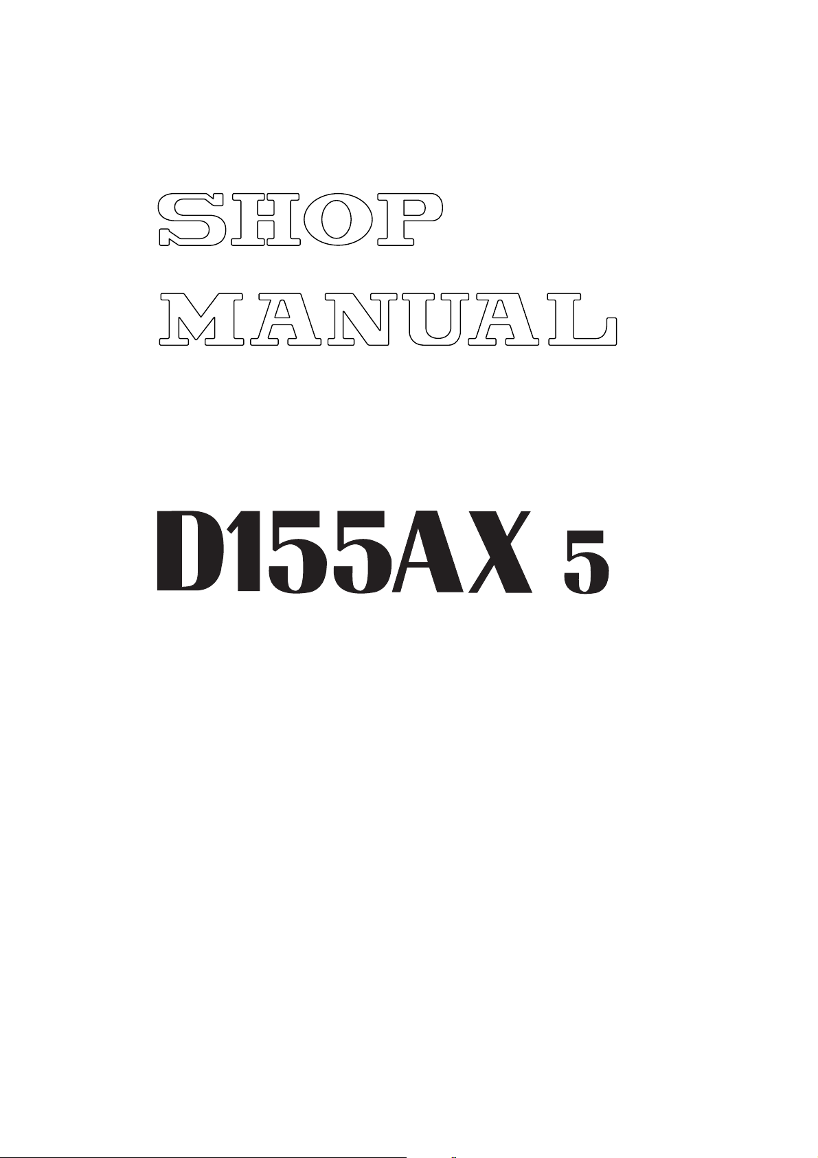
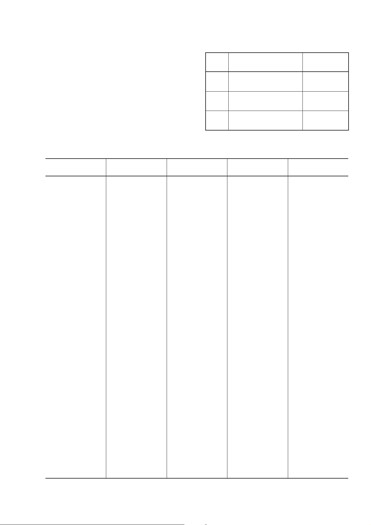
STARTING MOTOR
REMOVAL OF STARTING
MOTOR ASSEMBLY
Disconnect the cable from the negative (–) ter-
minal of the battery.
1. Open engine right side cover (top) and remove
cover (bottom).
2. Disconnect 3 starting motor wires (1) and 1 wiring connector (2).
3. Remove 3 bolts, then remove starting motor
assembly (3).
INSTALLATION OF STARTING
MOTOR ASSEMBLY
• Carry out installation in the reverse order to
removal.
Serial 70001 – 75000
2
1
DED00001
Serial No. 75001 and up
1
3
DED00002
30-26
5
D155AX-5
Page 13
DISASSEMBLY AND ASSEMBLY
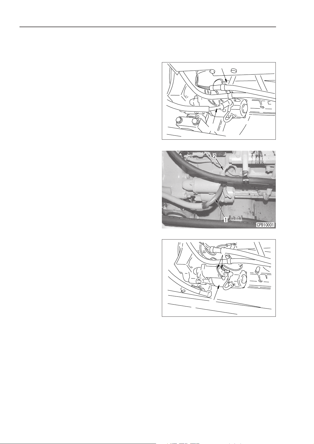
REMOVAL OF ALTERNATOR
ASSEMBLY
Disconnect the cable from the negative (–) ter-
minal of the battery.
1. Open engine right side cover (top) and remove
cover (bottom).
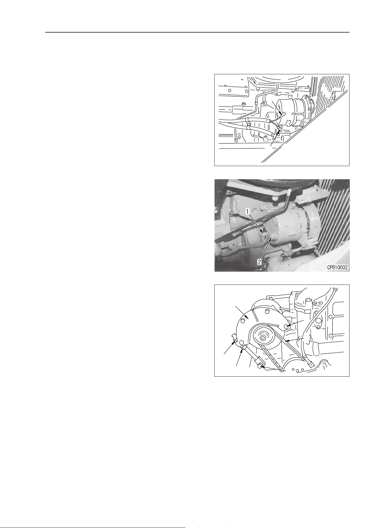
2. Disconnect alternator wiring (1) and (2).
3. Loosen locknut (3), then turn adjustment nut (4)
to loosen tension of V-belt (5).
4. Remove bolts (6) and (7), then remove alternator assembly (8) together with belt cover. 1
e Remove the V-belt from the pulley when re-
moving the alternator assembly.
ALTERNATOR
Serial No. 70001-75000
1
2
DED00003
Serial No. 75001 and up
INSTALLATION OF
ALTERNATOR ASSEMBLY
• Carry out installation in the reverse order to
removal.
1
e After installing the alternator, adjust the belt
tension. For details, see TESTING AND ADJUSTING, TESTING AND ADJUSTING ALTERNATOR BELT TENSION.
8
6
5
3
4
7
DED00004
D155AX-5
30-27
5
5
Page 14

DISASSEMBLY AND ASSEMBLY
REMOVAL OF ENGINE OIL
COOLER CORE ASSEMBLY
e Drain coolant.
ENGINE OIL COOLER
Serial No. 70001 – 75000
6
1. Remove wiring clamp (1).
2. Remove muffler water drain tube (2).
3. Remove adiabatic plate (3).
4. Disconnect turbocharger lubrication tube (4) at
turbocharger end, then move it towards rear.
5. Disconnect connector (5).
6. Remove oil cooler assembly (6).
7. Remove core assembly (8) from cover (7).
1
4
2
Serial No. 75001 and up
3
1
5
DED00005
INSTALLATION OF ENGINE OIL
COOLER CORE ASSEMBLY
• Carry out installation in the reverse order to
removal.
• Refilling with water
Add water through water filler to the specified
level.
e Run the engine to circulate the water through
the system. Then check the water level again.
78
DDD00006
30-28
5
D155AX-5
Page 15
DISASSEMBLY AND ASSEMBLY
DED00009
9
10
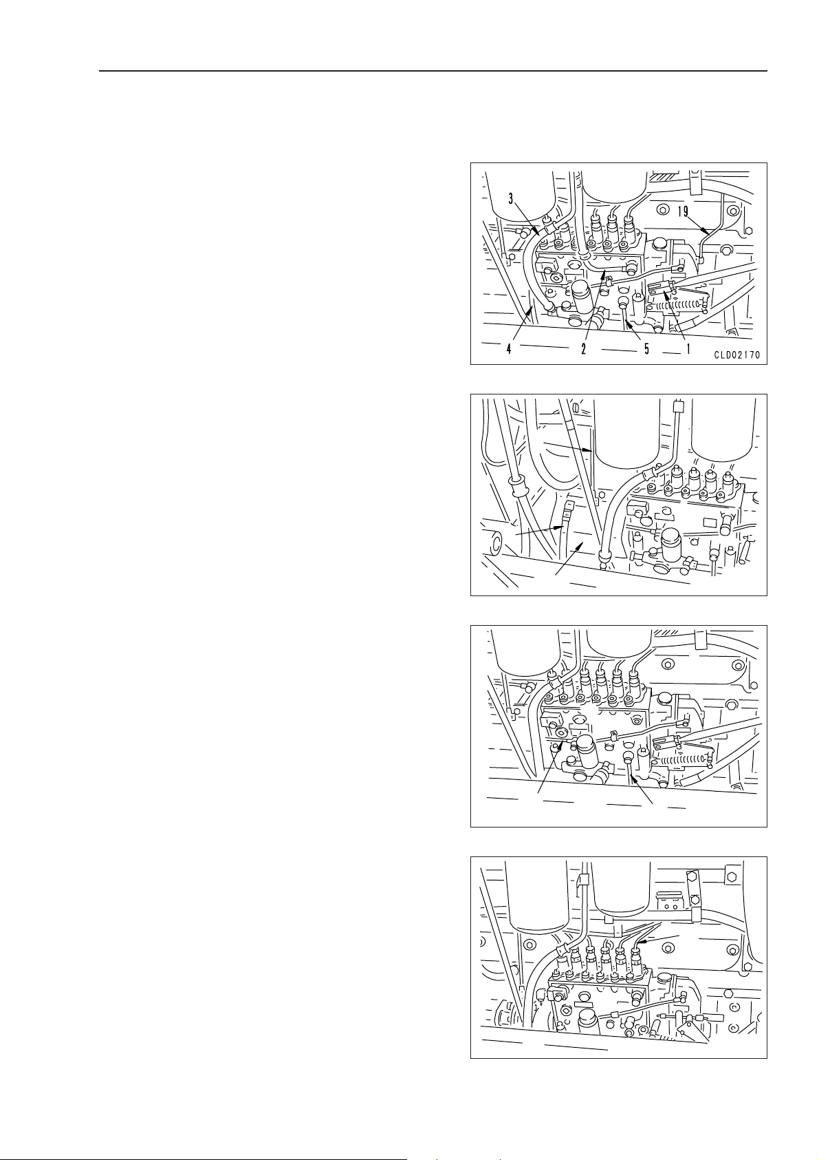
REMOVAL OF FUEL INJECTION
PUMP ASSEMBLY
Serial No. 70001 – 75000
1. Close valve of fuel supply piping.
2. Rotate crankshaft in normal direction and align
match mark of fuel injection pump.
fl This makes it easier to check the compres-
sion top dead center position of the No. 1
cylinder when installing the fuel injection
pump.
3. Open engine left side cover (top) and remove
cover (bottom).
4. Disconnect fuel control rod (1), and fuel hoses
(2), (3), (4), and (5). 1
FUEL INJECTION PUMP
7
5. Remove boost compensator tube (19).
6. Disconnect fuel hose (6) and tube (7).
7. Remove coupling cover (8).
8. Remove lubrication tubes (9) and (10).
9. Disconnect 6 delivery tubes (11). 2
6
8
DED00008
D155AX-5
11
DED00010
30-29
5
5
Page 16
DISASSEMBLY AND ASSEMBLY
10. Loosen tightening bolt (12) at drive shaft end,
and remove 4 pump mounting bolts (13).
11. Remove fuel injection pump assembly (14) to-
gether with coupling. 3
FUEL INJECTION PUMP
12
13
DED00011
14
INSTALLATION OF FUEL
INJECTION PUMP ASSEMBLY
Serial No. 70001 – 75000
• Carry out installation in the reverse order to
removal.
1
e Adjust the linkage. For details, see TEST-
ING AND ADJUSTING, ADJUSTING FUEL
CONTROL LINKAGE.
2
3 Sleeve nut: 123.5 ± 1.0 Nm {2.4 ± 0.1 kgm}
3
e Install the fuel injection pump as follows.
1) After installing pump assembly, align
damper (I,J) marks (15) and pointer (16)
correctly.
2) Loosen bolt of coupling (18) to align
match mark (17) of injection pump.
13
18
17
13
DED00012
16
15
DED00013
30-30
5
DED00014
D155AX-5
Page 17
DISASSEMBLY AND ASSEMBLY
3
4
5
DED00016
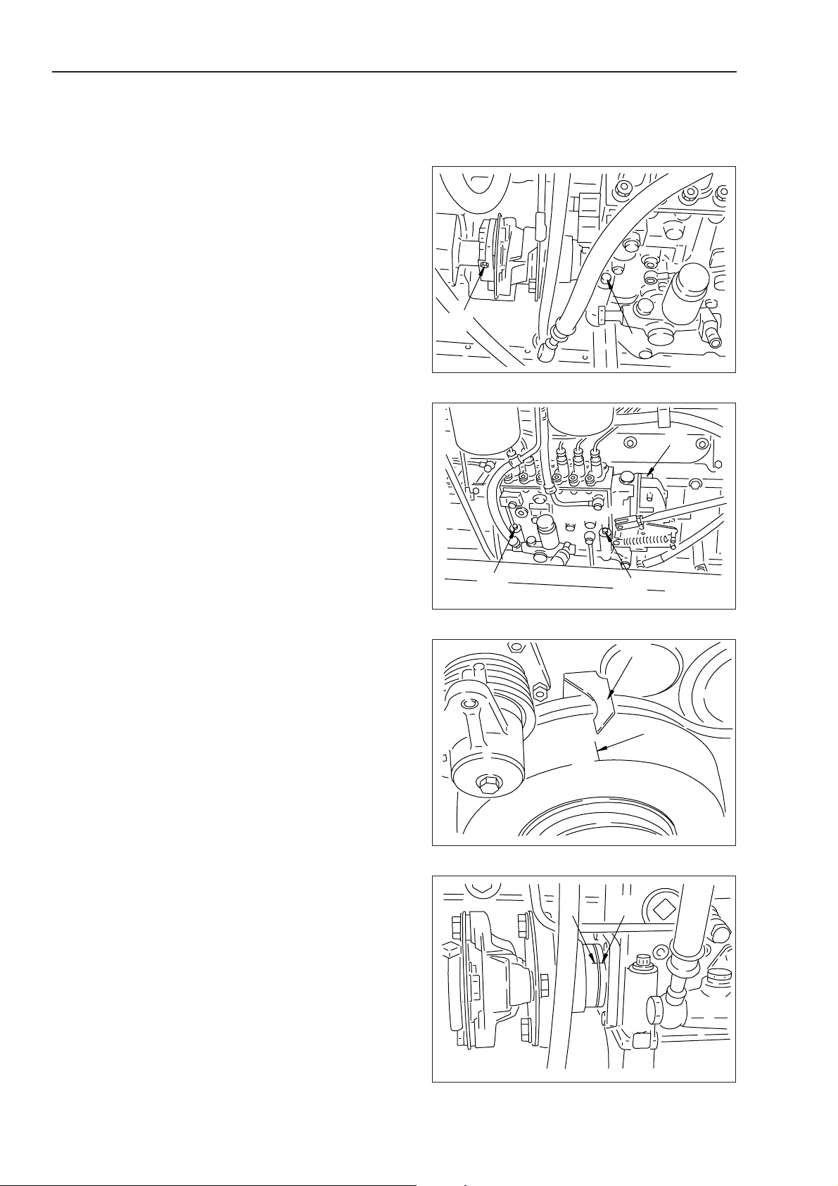
REMOVAL OF WATER PUMP
ASSEMBLY
1. Drain coolant.
2. Using an adjustable wrench, push tension pul-
ley (2) of fan belt (1), and remove fan belt.
3. Loosen locknut (3), then loosen adjustment nut
(4), and remove V-belt (5). 1
WATER PUMP
1
4. Remove connectors (6) and (7).
5. Remove pulley (8).
6. Remove water pump assembly (9).
INSTALLATION OF WATER
PUMP ASSEMBLY
• Carry out installation in the reverse order to
removal.
2
DED00015
Serial No. 70001 – 75000
Serial No. 75001 and up
1
e After installing the V-belt, adjust the belt ten-
sion. For details, see TESTING AND ADJUSTING, TESTING AND ADJUSTING ALTERNATOR BELT TENSION.
• Refilling with water
Add water through water filler to the specified
level.
e Run the engine to circulate the water through
the system. Then check the water level again.
8
D155AX-5
DED00018
30-31
1
5
Page 18
DISASSEMBLY AND ASSEMBLY
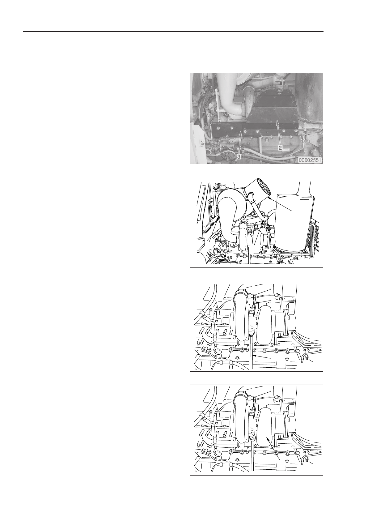
REMOVAL OF
TURBOCHARGER ASSEMBLY
Serial No. 70001 - 75000
1. Remove hood assembly.
For details, see REMOVAL OF HOOD ASSEMBLY.
2. Remove adiabatic covers (2) and (3).
3. Disconnect tube (4) and hose (5), then lift off air
cleaner assembly (6).
4 Air cleaner assembly: 35 kg
4. Disconnect lubrication hose (7) and drain tube
(8). 1
5. Remove turbocharger assembly (9). 2
TURBOCHARGER
INSTALLATION OF
TURBOCHARGER ASSEMBLY
Serial No. 70001 – 75000
• Carry out installation in the reverse order to
removal.
1
3 Hose mounting bolt:
66.2 ± 7.4 Nm {6.75 ± 0.75 kgm}
2
3 Turbocharger mounting bolt:
49.0 ± 9.8 Nm {5 ± 1 kgm}
6
5
4
DBD00026
7
8
DED00021
30-32
5
9
DED00020
D155AX-5
Page 19

DISASSEMBLY AND ASSEMBLY
REMOVAL OF
TURBOCHARGER ASSEMBLY
Serial No. 75001 and up
1. Remove hood assembly.
For details, see REMOVAL OF HOOD ASSEMBLY.
2. Remove adiabatic covers (1) and (2).
3. Disconnect tube (3) and hose (4), then lift off air
cleaner assembly (5).
4 Air cleaner assembly: 35 kg
4. Disconnect lubrication hose (6) and drain tube
(7). 1
5. Remove turbocharger assembly (8). 2
TURBOCHARGER
INSTALLATION OF
TURBOCHARGER ASSEMBLY
Serial No. 75001 and up
• Carry out installation in the reverse order to
removal.
1
3 Hose mounting bolt:
66.2 ± 7.4 Nm {6.75 ± 0.75 kgm}
2
3 Turbocharger mounting bolt:
49.0 ± 9.8 Nm {5 ± 1 kgm}
D155AX-5
30-32-1
5
Page 20

30-32-2 (Blank Page)
D155AX-5
Page 21
DISASSEMBLY AND ASSEMBLY
1
2
DBD00413
3
4
5
DBD00414
3
4
5
6
DBD00415
REMOVAL OF NOZZLE
HOLDER ASSEMBLY
Serial No. 70001 – 75000
1. Remove hood assembly.
For details, see REMOVAL OF HOOD ASSEMBLY.
2. Remove cylinder head cover (1). 1
e For No. 4 and 5 cylinders, remove the air
cleaner assembly and air supply connector.
3. Disconnect delivery tube (2). 2
4. Loosen locknut (3), and remove connector (4).
3
5. Remove holder (5). 4
6. Using tool A, remove nozzle holder assembly
(6). 5
NOZZLE HOLDER
INSTALLATION OF NOZZLE
HOLDER ASSEMBLY
Serial No. 70001 – 75000
• Carry out installation in the reverse order to
removal.
1
3 Cylinder head cover mounting bolt:
24.5 ± 4.9 Nm {2.5 ± 0.5 kgm}
2
3 Delivery tube sleeve nut:
23.5 ± 0.98 Nm {2.4 ± 0.1 kgm}
3
3 Connector:
31.9 ± 2.5 Nm {3.25 ± 0.25 kgm}
3 Locknut: 39.2 ± 4.9 Nm {4.0 ± 0.5 kgm}
4
3 Holder mounting bolt:
66.2 ± 7.4 Nm {6.75 ± 0.75 kgm}
5
e When assembling the nozzle holder, clean
the nozzle holder mount and check that there
is no dirt or dust inside the sleeve before
assembling.
Tighten the mounting bolts uniformly in turn
to prevent excessive tightening on one side.
A
6
DBD00416
D155AX-5
30-33
5
5
Page 22

DISASSEMBLY AND ASSEMBLY
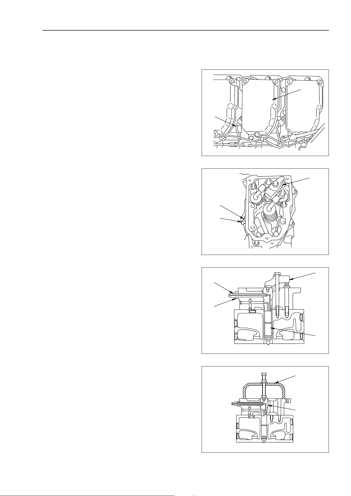
REMOVAL OF FUEL INJECTOR
ASSEMBLY
Serial No. 75001 and up
1. Remove hood assembly. For details, see RE-
MOVAL OF HOOD ASSEMBLY.
2. Remove common rail high-pressure pipe (1).
1
3. Disconnect wiring connector (2).
fl Insert a flat-head screwdriver in the slit of
the connector to press the stopper and disconnect the connector.
FUEL INJECTOR
4. Remove cylinder head cover (3). 2
fl For Nos. 4 and 5, remove the air cleaner
assembly and air intake connector.
5. Remove mounting bolts and rocker arm (4).
fl Loosen locknut (5) and then loosen adjust-
ment screw (6) by 2 - 3 turns so that an
excessive force will not be applied to the
push rod when the rocker arm is installed.
3
6. Remove 2 nuts (7) of solenoid valve above fuel
injector. 4
7. Pull out spring clamp (8) and disconnect clamp
(9).
8. Remove mounting bolts (12) of holder (11) of
connector (having an O-ring) (10) and to remove
holder, then insert connector (10) to remove it.
4
30-33-1
5
D155AX-5
Page 23

DISASSEMBLY AND ASSEMBLY
9. Remove holder (13) of fuel injector, then remove
injector assembly (14). 5
fl Do not hold the solenoid of the injector with
priers, etc. to remove the injector.
INSTALLATION OF FUEL
INJECTOR ASSEMBLY
Serial No. 75001 and up
• Carry out installation in the reverse order to
removal.
FUEL INJECTOR
1
3 High-pressure pipe sleeve nut:
39.2 ± 7.4 Nm {4.0 ± 5.0 kgm}
fl If there is any slit "b" or pit "c" on the taper
sealing part (Part "a": The part of 2 mm from
the end) of the high-pressure pipe joint or if
part "d" (Tape seal end: Part of 2 mm from
the end) has level difference that is felt with
a nail (or if part "d" is fatigued) and the fuel
may leak, replace the high-pressure pipe.
2
3 Cylinder head mounting bolt:
29.4 ± 34.3 Nm {3.0 ± 3.5 kgm}
3
fl When tightening the mounting bolts, check
that the ball of the adjustment screw is fitted to the socket of the push rod.
3 Rock arm mounting bolt:
93 ± 103 Nm {9.5 ± 10.5 kgm}
fl Adjust the valve clearance. For details, see
ADJUSTING VALVE CLEARANCE.
D155AX-5
30-33-2
5
Page 24

DISASSEMBLY AND ASSEMBLY
4
fl Method of installing wiring harness.
1) Fit O-ring (15).
2) Install cap (16).
3) Tighten nut (14).
4) Secure clamp with bolt (18).
3 Terminal nut:
1.8 ± 2.2 Nm {0.18 ± 0.22 kgm}
fl Eliminate the slack of the wiring harness and
press it against the injector body.
5
fl Method of installing fuel injector.
1) Install fuel injector assembly (14) and holder
(13) to the cylinder head temporarily.
2) Tighten mounting bolt (19) of holder (13)
temporarily.
3) Tighten sleeve (20) temporarily.
4) Tighten holder mounting bolt (19) se
curely.
5) Tighten sleeve (20) securely.
fl Apply engine oil to the spherical part of the
spherical washer.
ENGINE REAR SEAL
3 Holder mounting bolt:
58.8 ± 73.5 Nm {6.0 ± 7.5 kgm}
30-33-3
5
D155AX-5
Page 25

DISASSEMBLY AND ASSEMBLY
DAD00046
Make mark with punch
fl After installing the flywheel, use tool 1 to
measure the face runout and radial runout.
fl Face runout: Max. 0.30 mm
fl Radial runout: Max. 0.30 mm
ENGINE REAR SEAL
D155AX-5
30-41
1
Page 26

DISASSEMBLY AND ASSEMBLY
REMOVAL OF CYLINDER HEAD
ASSEMBLY
Serial No. 70001 – 75000
Disconnect the cable from the negative (-) ter-
minal of the battery.
1. Drain coolant.
2. Close fuel supply valve.
3. Remove hood assembly.
For details, see REMOVAL OF HOOD ASSEMBLY.
4. Remove engine side covers (left, right).
5. Remove adiabatic covers (2) and (3).
6. Disconnect tube (4) and hose (5), and lift off air
cleaner assembly (6).
4 Air cleaner assembly : 35 kg
CYLINDER HEAD
6
7. Remove tube (7), then lift off muffler assembly
(8).
4 Muffler assembly : 45 kg
8. Remove bracket (9).
9. Disconnect turbocharger lubrication hose (10)
and return tube (11). 1
5
10
4
DBD00026
8
7
DBD00027
9
30-42
5
11
DBD00028
D155AX-5
Page 27

DISASSEMBLY AND ASSEMBLY
DBD00041
i !8 !9o r!4 !5t !0 @2 @3!1
u!7 @0w q!3 !6y e@1 @4!2
DAD00042
@2 !8 !4 !0 y w e
u
!1
!5 !9 @3
@1 !7 !3 o t q r i !2 !6 @0 @4
INSTALLATION OF CYLINDER
HEAD ASSEMBLY
Serial No. 70001 – 75000
• Carry out installation in the reverse order to
removal.
1
3 Mounting bolt : 66.2 ± 7.4 Nm
{6.75 ± 0.75 kgm}
2
fl Tighten the bolts in the order 1 - 3 as
shown in the diagram on the right, then
tighten in the order 4 - N.
3 Exhaust manifold mounting bolt :
1st step : 29.4 ± 4.9 Nm
{3.0 ± 0.5 kgm}
2nd step : 66.2 ± 7.4 Nm
{6.75 ± 0.75 kgm}
3
3 Joint bolt : 29.4 ± 4.9 Nm
{1.15 ± 0.15 kgm)
4
fl Install the hoses without twisting or interfer-
ence.
3 Joint bolt : 29.4 ± 4.9 Nm
{3.0 ± 0.5 kgm}
5
fl Tighten the bolts in the order of 1 - N as
shown in the diagram on the right.
3 Intake manifold mounting bolt :
1st step : 29.4 ± 4.9 Nm
{3.0 ± 0.5 kgm}
2nd step : 66.2 ± 7.4 Nm
{6.75 ± 0.75 kgm}
6
3 Intake connector mounting bolt :
49.0 ± 9.8 Nm {5 ± 1 kgm}
7
3 Joint bolt : 8.8 ± 1.0 Nm
{0.9 ± 0.1 kgm}
8
3 Delivery tube sleeve nut :
23.5 ± 1.0 Nm {2.4 ± 0.1 kgm}
9
3 Head cover mounting bolt :
24.5 ± 9.8 Nm {2.5 ± 1.0 kgm}
0
fl Clean the mounting bolt oil holes before in-
stalling.
fl Check that the ball of the adjustment screw
is fitted properly into the socket of the push
CYLINDER HEAD
rod.
fl Adjust the valve clearance.
For details, see TESTING AND ADJUSTING, ADJUSTING VALVE CLEARANCE.
3 Rocker arm assembly :
98 ± 4.9 Nm {10 ± 0.5 kgm}
3 Locknut :
48.0 ± 2.9 Nm {4.9 ± 0.3 kgm}
A
fl Adjust the crosshead as follows.
1) Loosen locknut, then turn adjustment
screw back.
2) Press top of crosshead lightly and
tighten adjustment screw.
3) When adjustment screw contacts
valve stem, screw in a further 20°.
4) Tighten locknut to hold in position.
3 Locknut : 58.8 ± 5.9 Nm
{6.0 ± 0.6 kgm}
B
3 Locknut : 39.2 ± 4.9 Nm
{4.0 ± 0.5 kgm}
D155AX-5
30-47
5
Page 28

DISASSEMBLY AND ASSEMBLY
C
3 Connector : 31.9 ± 2.5 Nm
{3.25 ± 0.25 kgm}
D
3 Holder mounting bolt : 66.2 ± 7.4 Nm
{6.75 ± 0.75 kgm}
CYLINDER HEAD
2
3
6
E
fl Check that there is no dirt or dust on the
cylinder head mounting surface or inside the
cylinder.
fl When installing the gasket, check that the
grommet does not come out.
fl Coat the bolt thread and seat face completely
with molybdenum disulphide (LM-P).
fl Tighten the cylinder head mounting bolts in
the order given in the diagram.
2 Cylinder head mounting bolt :
Anti-friction compound (LM-P)
3 Cylinder head mounting bolt :
1st step : Tighten to 147 ± 9.8 Nm
{15 ± 1 kgm}
2nd step : Tighten to 215.6 ± 4.9 Nm
{22 ± 0.5 kgm}
3rd step : 1) When using tool B
• Using an angle tightening
wrench, tighten bolt 90° .
2) When not using tool B
• Make marks on bolt and flywheel with a felt pen, then
tighten bolt 90°.
+30°
0
5
1
Make marks on
cylinder head and bolt
4
7
DAD00043
B
DBD00044
+30
90°
0
fl Tighten bolt 7 to 66.2 ± 7.4 Nm {6.75 ± 0.75
kgm} one time.
fl After tightening, make one punch mark on
the bolt head to indicate the number of times
it has been tightened.
• If any bolt already has five punch marks,
do not reuse it. Replace it with a new
bolt.
• Refilling with water
• Add water through water filler to the speci-
fied level.
fl Run the engine to circulate the water through
the system. Then check the water level
again.
30-48
1
DAD00045
Make mark with punch
DAD00046
D155AX-5
Page 29

DISASSEMBLY AND ASSEMBLY
1
2
3
DBD00421
REMOVAL OF THERMOSTAT
ASSEMBLY
1. Drain coolant.
2. Remove alternator assembly.
For details, see REMOVAL OF ALTERNATOR ASSEMBLY.
3. Disconnect radiator inlet hose (1).
4. Disconnect bypass tube (2).
5. Remove cover (3).
6. Remove 2 thermostats (4).
THERMOSTAT
INSTALLATION OF
THERMOSTAT ASSEMBLY
• Carry out installation in the reverse order to
removal.
• Refilling with water
Add water through water filler to the specified
level.
fl Run the engine to circulate the water through
the system. Then check the water level
again.
4
4
DBD00422
D155AX-5
30-49
1
Page 30

DISASSEMBLY AND ASSEMBLY
REMOVAL OF AIR
CONDITIONER COMPRESSOR
ASSEMBLY
AIR CONDITIONER COMPRESSOR
Serial No. 70001 – 75000
Using tool X, collect freon gas (R134a).
1. Open engine left side cover (top) and remove
cover (bottom).
2. Remove wiring connector (1).
3. Disconnect hoses (2) and (3). 1
fl Fit blind plugs to prevent dirt or water from
entering the hoses.
4. Loosen 4 mounting bolts (4).
5. Remove V-belt cover (5).
6. Loosen adjustment bolt (6) and remove.
7. Remove mounting bolts (4), remove V-belt (7)
from pulley, then remove compressor assembly
(8). 2
123
4
DBD00423
Serial No. 70001 – 75000
6
5
Serial No. 70001 – 75000
4
7
Serial No. 75001 and up
DBD00424
8
DBD00425
30-50
5
D155AX-5
Page 31

DISASSEMBLY AND ASSEMBLY
3
DED00438
4
5
DED00439
REMOVAL OF ENGINE
ASSEMBLY
Serial No. 70001 – 75000
Disconnect the cable from the negative (–) ter-
minal of the battery.
fl Close the supply valve of the fuel tank.
1. Remove radiator, oil cooler, guard assembly.
For details, see REMOVAL OF RADIATOR, OIL
COOLER, GUARD ASSEMBLY.
2. Disconnect starting motor wiring (1).
3. Disconnect engine speed sensor connectors (2)
(CN009, CN010).
ENGINE
1
DED00436
4. Disconnect wiring connector (3) (CN101).
5. Disconnect 2 air conditioner hoses (4). 1
fl Loosen the sleeve nut slightly, and release
the air conditioner gas (R134a) completely
before disconnecting the hose.
fl Fit blind plugs to prevent dirt or water from
entering the hoses.
fl Disconnect at the air conditioner end, then
remove all the clamps from the floor frame
and move towards the engine.
6. Disconnect 2 heater hoses (5).
fl Disconnect at the air conditioner end, then
move towards the engine.
2
DED00437
D155AX-5
30-63
5
Page 32

DISASSEMBLY AND ASSEMBLY
DED00441
10
7. Disconnect fuel supply hose (6).
8. Disconnect fuel return hose (7).
ENGINE
9. Disconnect fuel control rod (8).
10. Disconnect ground wiring (9).
11. Disconnect universal joint (10) at damper end.
12. Remove front mount bolts (11) and rear mount
bolts (12). 2
11
8
9
7
6
DED00440
12
13. Move engine assembly (13) towards front of
machine, and lift off gradually.
fl Be careful not to damage the wiring or hoses
when removing the engine assembly.
4 Engine assembly : 1,750 kg
30-64
1
DDD00442
13
DED00443
D155AX-5
Page 33

DISASSEMBLY AND ASSEMBLY
Serial No. 75001 and up
¤ Disconnect the cable from the negative (-) ter-
minal of the battery.
fl Close the fuel feed valve.
1. Remove radiator and oil cooler and guard assembly. For details, see REMOVAL OF RADIATOR AND OIL COOLER AND GUARD ASSEMBLY.
2. Disconnect starting motor wiring (1).
3. Disconnect wiring connector (2).
ENGINE
4. Disconnect 2 air conditioner house (3). 1
fl Loosen the sleeve nut of each hose a little to
discharge the all air conditioner refrigerant
(R134a), then disconnect the hose.
fl Plug the hoses to prevent dirt, water, etc.
from entering them.
fl Remove the all clamps on the floor frame
and move the hoses toward the engine.
5. Disconnect 2 heater hoese (4).
6. Disconnect air conditioner wiring connector (5).
7. Disconnect fuel hoses (6), (7), and (8).
D155AX-5
30-64-1
5
Page 34

DISASSEMBLY AND ASSEMBLY
8. Disconnect ground wire (9).
9. Disconnect universal joint (10) from damper.
ENGINE
10. Remove front mounting bolts (11) and rear
mounting bolts (12). 2
11. Moving engine assembly (13) to front of machine body, lift it off gradually.
fl After removing the engine assembly, take
care not to damage the wires, hoses, etc.
4 Engine assembly : 1,750 kg
30-64-2
5
D155AX-5
Page 35

DISASSEMBLY AND ASSEMBLY
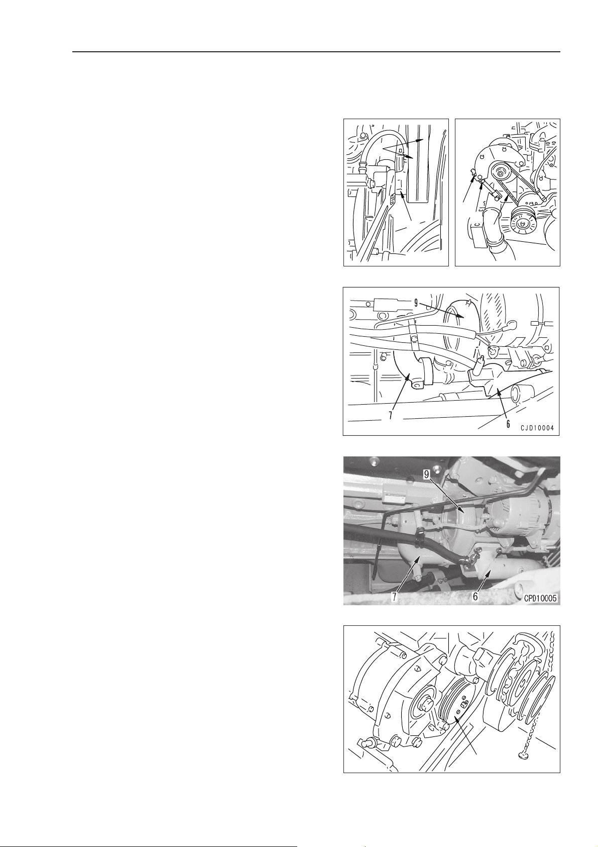
REMOVAL OF POWER TRAIN
UNIT ASSEMBLY
Serial No. 70001 – 75000
¤ Park the machine on level ground, lower the
work equipment completely to the ground, then
disconnect the cable from the negative (-) terminal of the battery.
1. Drain oil
6 Hydraulic tank : Approx. 97 ¬
6 Power train case: Approx. 60 ¬
2. Remove floor frame assembly.
For details, see REMOVAL OF FLOOR FRAME
ASSEMBLY.
POWER TRAIN UNIT
3. Open bottom plate at bottom of power train
unit.
4. Remove cover (1) at bottom of fuel tank.
5. Close lever (2) of fuel valve.
6. Disconnect hose (3) leading to priming pump.
7. Disconnect fuel return hoses (4) and (5).
8. Disconnect fuel level sensor wiring connector
(6) (CN422).
9. Lift off fuel tank assembly (7).
fl Sling at three points and use a lever block at
the center to keep the tank horizontal.
fl Move the tank to the rear, and when it clears
the floor frame, raise the rear of the tank
slightly with the lever block. (Do this to
avoid interference with the ripper hoses.)
4 Fuel tank assembly (when full) : 760 kg
10. Disconnect engine speed sensor wiring connec-
tor (8).
11. Disconnect suction tube (9) of 3-spool pump
(HSS lubrication, torque converter, transmission
charge).
fl Remove the cover at the top of the pump.
D155AX-5
30-75
5
Page 36

DISASSEMBLY AND ASSEMBLY
12. Remove suspension rod (10).
13. Remove top cover of centralized pressure detec-
tion port, then remove centralized pressure detection block (11) from frame.
POWER TRAIN UNIT
14. Disconnect hose (12) between hydraulic pump
and control valve.
15. Disconnect wiring connector (13) (HHP).
16. Remove suction tube (14).
fl Be careful not to damage the gasket of the
joint.
17. Disconnect hose (15) between cooler bypass
valve and hydraulic tank.
18. Disconnect hose (16) between charge relief valve
and hydraulic tank.
19. Remove power train oil supply pipe (17).
20. Disconnect power train dipstick tube (18) from
case, and move towards right side of chassis.
30-76
1
D155AX-5
Page 37

DISASSEMBLY AND ASSEMBLY
33. Lift off power train unit assembly (34). 5
fl Check that the wiring and piping has all been
removed, then lift off the power train unit
assembly.
4 Power train unit assembly : 2800 kg
INSTALLATION OF POWER
TRAIN UNIT ASSEMBLY
POWER TRAIN UNIT
Serial No. 70001 – 75000
• Carry out installation in the reverse order to
removal.
1
3 Universal joint mounting bolt :
110.3 ± 22.1 Nm {11.3 ± 2.3 kgm}
2
3 Mount cap mounting bolt :
277.5 ± 32.4 Nm {28.3 ± 3.3 kgm}
3
fl Clamp the protruding portion of the cou-
pling seal, then assemble the clamp thread
so that it is parallel to the cap mount seat
surface.
4
3 Front mount mounting bolt :
926.8 ± 103.0 Nm {94.5 ± 10.5 kgm}
5
fl When assembling the power train assem-
bly, be extremely careful not to damage seal
(32).
• Refilling with oil (Hydraulic tank. power train
case.)
Add engine oil through oil filler to the specified
level.
fl Run the engine to circulate the oil through
the system. Then check the oil level again.
5 Hydraulic tank : Approx. 97 ¬
5 Power train case : Approx. 60 ¬
D155AX-5
30-79
5
1
Page 38

DISASSEMBLY AND ASSEMBLY
SEPARATION OF POWER
TRAIN UNIT ASSEMBLY
• Drain oil
Before setting the power train unit assembly on
the block, drain the oil from the PTO case.
1. Raise power train unit assembly (1) and set on
block 1.
4 Power train unit assembly : 2800 kg
2. Disconnect 3 hoses (2) connected to cooler by-
pass valve.
3. Disconnect HSS pump connecting hose (3).
4. Remove cooler bypass valve assembly (4) to-
gether with bracket.
POWER TRAIN UNIT
5. Disconnect 5 charge relief valve connecting
hoses (5).
6. Disconnect wiring connector (6) (CN406).
7. Remove charge relief valve (7).
8. Disconnect pressure detection hoses (8) and (9),
and remove reducing pressure valve hose (10).
1
fl Disconnect the transmission modulation
pressure detection hose.
10
8
9
DBD00927
30-80
1
D155AX-5
Page 39

DISASSEMBLY AND ASSEMBLY
DLD01003
18
19
DLD01005
21
22
108
4) Remove brake drum (12) together with disc
and plate.
HSS CASE
12
DKD01001
5) Remove plate (13), disc (15), spring (16), and
plate (14) from brake drum.
6) Remove mounting bolts, then remove car-
rier assembly (19) from hub (18).
7) Remove gear assembly (20) from hub as-
sembly (18).
14
16
18
13
15
DKD01002
20
8) Remove ring (21), then remove ring gear
(22) from gear (108).
9) Remove snap ring (23), and pull out shaft
(24).
D155AX-5
23
DLD01004
24
DLD01006
30-121
1
5
Page 40

DISASSEMBLY AND ASSEMBLY
E2
DLD01010
39
10) Remove planetary gear (25), bearing (26),
thrust washer (27), shaft (24), and ball (28).
HSS CASE
25
11) Remove snap ring (31), then remove stopper (32) from hub (18).
26
27
32
31
24
28
DLD01007
18
DKD01008
2. Bevel pinion assembly
1) Using guide bolts 3 and forcing screws remove bevel pinion assembly (33) and shim
(34).
fl Check the number and thickness of the
shims, and keep in a safe place.
2) Disassembly of bevel pinion assembly
i) Remove bolts (35), (36) and pin (37).
Serial No. 75001 –
ii) Hold with press to prevent pinion from
moving, then use tool E2 to remove
locknut (39).
iii) Using push tool 5, remove bevel pinion
(40) from cage (41).
34
r
41
e
33
DLD01009
t
40
30-122
5
DKD01011
D155AX-5
Page 41

DISASSEMBLY AND ASSEMBLY
iv) Remove bearing (42).
v) Remove outer races (43) and (107) from
cage (41).
42
DLD01012
43
HSS CASE
107
41
DLD01013
vi) Remove bearing (109) from bevel pinion
(40).
3. Sun gear
Remove sun gear (45).
fl Remove the sun gear on the opposite side
in the same way.
4. Gear
1) Remove snap ring (47), then remove spacer
(48).
40
45
109
DLD01014
47
48
2) Using gear puller 6, remove gear (49).
D155AX-5
y
DLD01015
DLD01016
49
DLD01017
30-123
5
Page 42

DISASSEMBLY AND ASSEMBLY
DLD01021
57
58
HSS CASE
fl Only inner race (50) of bearing (55) will re-
main.
fl Remove the gear on the opposite side in the
same way.
5. Valve seat
1) Pull out 2 brake circuit tubes (51) and 3 lubrication tubes (52), then remove.
2) Remove valve seat (53).
51
52
49
55
51
50
DKD01018
52
53
51
DKD01019
6. Lubrication tubes, dipstick tube, suction tube
1) Remove lubrication tubes (52) and (56).
2) Remove lubrication tubes (57) and (58).
3) Remove dipstick tube (59) and suction tube
(60).
52
56
DLD01020
59
30-124
5
1
60
DLD01022
D155AX-5
Page 43

DISASSEMBLY AND ASSEMBLY
• Serial No. 75001 –
vi) Turn the nut unit the phase of any one
of the pin insertion holes of the nut (8
places) is matched to that of any one of
the pin insertion holes of the pinion shaft
(5 places). (Returning angle: 0 - 9°)
vii) Insert pin (37) in the above holes. Fit
plate (36) and tighten bolts (35).
2 Bolt : Thread tightener (LT-2)
3 Bolt : 11.8 - 14.7 Nm
{1.2 - 1.5 kgm}
2) Using guide bolt 3, assemble shim (34) and
install bevel pinion assembly (33).
fl There are three types of shim:
0.1, 0.2, 0.5 mm
HSS CASE
y
6. Adjusting tooth contact, backlash
1) Adjusting backlash
Put the probe of dial gauge 6 at right angles in contact with the tip of the bevel gear
teeth. Hold the bevel pinion in position, and
read the measurement when the bevel gear
is moved forward and backward.
fl Standard value for backlash :
fl Measure at least three points on oppo-
site sides.
• If the result of the inspection shows that
the correct backlash is not being obtained, adjust as follows.
fl Adjust the shim thickness at the left cage.
• If backlash is too small
Loosen mounting bolt of cage and remove shim.
• If backlash is too large
Loosen mounting bolt of cage and add
shim.
DBD00156
0.25 - 0.33 mm
Front
A
DAD00157
D155AX-5
Front
B
DAD00158
30-135
1
5
Page 44

DISASSEMBLY AND ASSEMBLY
HSS CASE
2) Adjusting tooth contact
Testing
i) Coat the tooth face of the bevel pinion lightly
with red lead (minium). Rotate the bevel
gear forward and backward and inspect the
pattern left on the teeth.
ii) Tooth contact should be checked as follows
(from tip of teeth of bevel pinion).
a) Center of tooth contact: 20 - 40 % of
tooth width (from small end)
b) Width of tooth contact: 30 - 50 % of tooth
width
c) Center of tooth contact: 35 - 65 % of
tooth height (from root of tooth)
d) Width of tooth contact: 60 - 80 % of tooth
height
In addition, there should be no strong contact at the addendum or dedendum (tip or
root of the gear teeth) or at the big and
small ends.
fl If the gears are adjusted to this pattern,
the tooth contact will be correct when
load is applied.
Big
end
Root of tooth
Big end
Tip of tooth
Small end
DBD00159
b
a
c
d
Small
end
Adjustment
If the result of the inspection shows that the
correct tooth contact is not being obtained, adjust again as follows.
i) If bevel pinion is too far from center line of
bevel gear.
Contact is at the small end of the convex
tooth face of the bevel gear and at the big
end of the concave tooth face.
• Correct the tooth contact as follows.
Adjust the thickness of the shims at the bevel
pinion to move the bevel pinion in direction
A.
Move the bevel gear in direction B, then
check the tooth contact pattern and backlash again.
ii) If bevel pinion is too close to center line of
bevel gear.
Contact is at the big end of the convex tooth
face of the bevel gear and the small end of
the concave tooth face.
• Correct the tooth contact as follows.
Adjust the thickness of the shims at the bevel
pinion to move the bevel pinion in direction
B.
Move the bevel gear in direction A, then
check the tooth contact pattern and backlash again.
DBD00160
B
A
DBD00161
B
A
DBD00162
30-136
1
D155AX-5
Page 45

DISASSEMBLY AND ASSEMBLY
4
DKD01083
107
108
109
DAD02453
iii) Using eyebolts 1, align bolt hole with
hub and brake drum, then install brake
cover assembly (5).
fl Tighten the mounting bolts tempo-
rarily.
fl The force of the spring is applied, so
tighten the hexagon socket head
bolts uniformly.
iv) Using push tool, press fit inner race (4).
v) Install plate (3) and flange (2).
3 Flange: 58.8 - 73.6 Nm
{6 - 7.5 kgm}
vi) Fully tighten bolts temporarily tightened
in Step iii).
3 Mounting bolt: 98.1 - 122.6 Nm
{10 ± 12.5 kgm}
HSS CASE
q
5
DLD00999
23
• Installation of brake, carrier assembly
1) Angle steering case assembly approx. 15°
so that tool E1 is perpendicular to ground
surface.
2) Using tool E1, install brake, carrier assembly
(1).
3 Mounting bolt: 98.1 - 122.6 Nm
{10 - 12.5 kgm}
fl Assemble the brake, carrier assembly on
the opposite side in the same way.
fl When cover (109) of the rear surface on
HSS case (107) has been removed, install new gasket (108).
2 Gasket (apply to both surfaces):
Gasket sealant (LG-1)
DLD01255
E1
1
DLD00997
D155AX-5
30-141
1
Page 46

DISASSEMBLY AND ASSEMBLY
REMOVAL OF HYDRAULIC
PUMP ASSEMBLY
¤ Park the machine on level ground, lower the
work equipment completely to the ground, then
disconnect the cable from the negative (–) terminal of the battery.
1. Drain hydraulic oil and power train oil.
6 Hydraulic oil : Approx. 97 ¬
6 Power train case : Approx. 60 ¬
2. Remove cab.
For details, see REMOVAL OF CAB ASSEMBLY.
3. Lift off operator’s seat assembly (1).
4 Operator’s seat : 54 kg
HYDRAULIC PUMP
Serial No. 70001 – 75000
4. Remove floor frame left and right side covers
(2).
5. Remove floor mat, then remove cover (3).
Serial No. 75001 and up
30-142
1
5
D155AX-5
Page 47

DISASSEMBLY AND ASSEMBLY
6. Disconnect acceleration rod (4) from yoke.
7. Disconnect deceleration rod (5) from yoke.
8. Disconnect brake rod (6).
fl Loosen locknut (7), and turn joint (8) to dis-
connect.
Joint (8) has a reverse thread.
9. Remove floor assembly (9).
HYDRAULIC PUMP
4 Floor assembly: 26 kg
A. Removal of hydraulic pump assembly
1) Disconnect hose (1) leading to work equipment control valve.
2) Disconnect wiring connector (2) (HHP).
3) Disconnect suction tube joints (3) and (4).
4) Remove 4 mounting bolts (5), then remove
tube (6).
5) Remove mounting bolts, then remove hydraulic pump assembly (7).
4 Hydraulic pump assembly : 19 kg
D155AX-5
30-143
1
5
Page 48

DISASSEMBLY AND ASSEMBLY
B. Removal of 3-spool pump assembly (HSS lubri-
cation + torque converter, transmission charge
+ torque converter charge pump)
1) Remove cover (1).
2) Disconnect HSS motor and brake lubrication
tube (2).
3) Disconnect suction tube (3) from power train
case.
4) Disconnect transmission filter hose (4).
HYDRAULIC PUMP
5) Disconnect filter bypass valve hose (5).
fl It is difficult to disconnect the hose at
the pump end.
6) Remove mounting bolts, then lift off 3-spool
pump assembly (6).
fl Remove together with hose (5).
4 3-spool pump assembly : 24 kg
30-144
1
5
D155AX-5
Page 49

DISASSEMBLY AND ASSEMBLY
C. Removal of HSS pump assembly
1) Disconnect HSS and PPC charge valve hose
(1).
2) Disconnect cooler bypass valve hose (2).
3) Disconnect charge filter hose (3).
4) Disconnect solenoid wiring connector (4)
(PUP.A).
5) Disconnect cooler bypass valve hose (5).
6) Disconnect HSS motor hoses (6) and (7).
7) Disconnect charge relief valve hose (8).
HYDRAULIC PUMP
8) Disconnect engine speed sensor wiring con-
nector (9) (CN010).
9) Disconnect solenoid wiring connector (10)
(PUP.B).
10) Remove mounting bolts, then lift off HSS
pump assembly (10).
4 HSS pump assembly : 116 kg
D155AX-5
30-145
1
5
Page 50

DISASSEMBLY AND ASSEMBLY
D. Removal of charge + scavenging pump assembly
1) Disconnect charge filter hose (1).
fl It is difficult to disconnect the hose at
the pump end.
2) Disconnect power train case suction tube (2).
3) Disconnect suction hydraulic tank tube (3).
HYDRAULIC PUMP
4) Lift off charge + scavenging pump assembly
(4).
fl Raise, then move slowly towards the en-
gine, and lower gradually from clearance.
4 Charge + scavenging pump assembly :
30 kg
INSTALLATION OF HYDRAULIC
PUMP ASSEMBLY
• Carry out installation in the reverse order to
removal.
• Refilling oil
5 Hydraulic oil : Approx. 97 ¬
5 Power train case : Approx. 60 ¬
• Bleeding air
Bleed the air from the pumps and power train.
For details, see TESTING AND ADJUSTING,
Bleeding air.
30-146
1
5
D155AX-5
Page 51

DISASSEMBLY AND ASSEMBLY
HSS, PPC CHARGING VALVE
DISASSEMBLY OF HSS, PPC CHARGING VALVE ASSEMBLY
12
13
20
16
15
19
5
21
18
22
17
14
1
3
4
11
7
10
9
8
6
2
23
DKD01197
1. Remove plug (1), then remove springs (3) and
(4) from valve body (2).
2. Remove plug (5), then remove spool assembly
(6).
3. Remove valve (8), spring (9), valve (10), and
shim (11) from spool (7).
4. Remove plug (12), then remove spring (13).
5. Remove plug (14), then remove spool assembly
(15).
6. Remove valve (17), spring (18), and valve (19)
from spool (16).
7. Remove plug (20), then remove spring (21) and
valve (22).
8. Remove plug (23).
D155AX-5
30-151
1
5
Page 52

DISASSEMBLY AND ASSEMBLY
HSS, PPC CHARGING VALVE
ASSEMBLY OF HSS, PPC CHARGING VALVE ASSEMBLY
12
13
20
16
15
19
14
21
22
1
17
18
11
7
10
9
8
6
5
2
23
4
3
DKD01197
fl Clean all parts, and check for dirt or dam-
age. Coat the sliding surfaces of all parts
with engine oil before installing.
1. Tighten plug (23).
2. Assemble valve (22) and spring (21) to valve
body (2), and tighten plug (20).
3. Assemble valve (19), spring (18), and valve
(17) to spool (16).
4. Assemble spool assembly (15) to valve body
(2), and tighten plug (14).
3 Plug : 63.7 ± 14.7 Nm {6.5 ± 1.5 kgm}
5. Assemble spring (13) and tighten plug (12).
3 Plug : 68.6 ± 9.8 Nm {7 ± 1 kgm}
6. Assemble valve (10), spring (9), valve (8),
and shim (11) to spool (7).
fl Check the number and thickness of the
shims, then assemble.
Shim thickness: 0.5 mm
No. of shims: 4
7. Assemble spool assembly (6) to valve body
(2) and tighten plug (5).
3 Plug : 68.6 ± 9.8 Nm {7 ± 1 kgm}
8. Assemble springs (4) and (3), and tighten
plug (1).
3 Plug : 68.6 ± 9.8 Nm {7 ± 1 kgm}
30-152
1
5
5
D155AX-5
Page 53

DISASSEMBLY AND ASSEMBLY
REMOVAL OF TRANSMISSION
CONTROL VALVE ASSEMBLY
¤ Park the machine on level ground, lower the
work equipment completely to the ground, then
disconnect the cable from the negative (–) terminal of the battery.
1. Remove operator’s seat and floor plate.
For details, see REMOVAL OF HYDRAULIC PUMP
ASSEMBLY.
2. Disconnect hose brackets (1) and (2) from transmission case cover.
3. Disconnect speed control cable (3), and remove
bracket from case cover.
fl Do not disconnect the cable from the bracket.
TRANSMISSION CONTROL VALVE
4. Disconnect directional control cable (4), and re-
move bracket from case cover.
fl Do not disconnect the cable from the bracket.
5. Disconnect transmission modulation pressure
detection hose (5).
6. Disconnect wiring connector of gear speed detection limit switch (5-1).
• Serial No. Only 75001 and up
7. Disconnect backup alarm limit switch wiring connector (6) (CN251), and remove limit switch (7).
8. Using forcing screws, remove transmission cover
(8). 1
9. Disconnect hose (9) coming from charge pump,
and remove plate (10).
10. Remove sleeve (11), then remove block (12).
D155AX-5
30-153
1
5
Page 54

DISASSEMBLY AND ASSEMBLY
10. Remove sleeves (13) and (14). 2
11. Remove block (15), then remove sleeve (16).
3
12. Remove mounting bolts, then remove transmis-
sion control valve assembly (17). 4
INSTALLATION OF
TRANSMISSION CONTROL
VALVE ASSEMBLY
• Carry out installation in the reverse order to
removal.
TRANSMISSION CONTROL VALVE
1
fl Look through the inspection window in the
cover to check that the lever and yoke are
meshed, then tighten the mounting bolts.
fl When installing the cover, tap with a plastic
hammer. If the dowel pin portion is not
inserted, remove the cover, correct the meshing of the lever and yoke, then install again.
23
2 Sleeve : Grease (G2-LI)
4
3 Transmission control valve mounting bolt :
49.0 ± 4.9 Nm {5.0 ± 0.5 kgm}
30-154
1
D155AX-5
Page 55

DISASSEMBLY AND ASSEMBLY
INSTALLATION OF BLADE PPC
VALVE ASSEMBLY
• Carry out installation in the reverse order to
removal.
1 2 3
e The connection position for the pump hose,
drain hose, and PPC hose are distinguished
by color bands at the caulking portion for
the hoses, so check the colors when connecting.
4
e Set the PPC valve in the mounting direction
shown in the diagram on the right when
installing.
(The diagram on the right shows the PPC
valve as seen from the top of the panel.)
Front of
machine
P4
BLADE PPC VALVE
T
P2
(View of valve from above)
P1
P
P3
DAD00788
• Refilling with oil (hydraulic tank)
Add engine oil through oil filler to the specified
level.
e Run the engine to circulate the oil through
the system. Then check the oil level again.
D155AX-5
30-269
1
1
Page 56

DISASSEMBLY AND ASSEMBLY
REMOVAL OF RIPPER PPC
VALVE ASSEMBLY
Fully lower work equipment to the ground. Re-
lease the remaining pressure in the circuit. For
details, see TESTING AND ADJUSTING, RELEASING REMAINING PRESSURE IN HYDRAULIC CIRCUIT. Then loosen the oil filler cap slowly to
release the pressure inside the hydraulic tank.
1. Remove operator’ seat, remove 1 cover on inside right, then remove side cover on right side
of chassis.
4 Operator’s seat: 50 kg
2. Remove cover (1).
e Disconnect the horn switch connector
(CN262) at the same time.
RIPPER PPC VALVE
3. Loosen lock bolt of lever (2), and pull out lever
(2) together with boot.
4. Remove lever guide.
Serial No. Only 75001 and up
5. Disconnect pump hose (4). 1
6. Disconnect drain hose (5). 2
7. Disconnect PPC hose (6). 3
7. Remove ripper PPC valve assembly (7). 4
4
5
6
6
DBD00791
30-270
1
5
D155AX-5
Page 57

DISASSEMBLY AND ASSEMBLY
5
5
6
DED01133
6
DED01134
7
8
9
REMOVAL OF OPERATOR CAB
ASSEMBLY
OPERATOR CAB
Serial No. 70001 – 75000
Disconnect the cable from the negative (–) ter-
minal of the battery.
1. Remove ROPS guard.
For details, see REMOVAL OF ROPS GUARD.
2. Open left side cover.
3. Disconnect connectors (1) (CN360), (2) (CN-
CAB1), and (3) (CN-CAB2).
4. Disconnect 4 washer hoses (4). 1
5. Remove step (5), then remove cover (6).
6. Remove garnishes (7), (8), and (9).
7. Remove 19 mounting bolts, then lift off opera-
tor cab assembly (10).
4 Operator cab assembly: 290 kg
2
3
4
1
DED01132
INSTALLATION OF OPERATOR
CAB ASSEMBLY
Serial No. 70001 – 75000
• Carry out installation in the reverse order to
removal.
1
e Match the color bands and connect the
washer hoses.
10
DED01135
30-297
1
5
D155AX-5
Page 58

DISASSEMBLY AND ASSEMBLY
REMOVAL OF HOOD
ASSEMBLY
HOOD
1. Remove exhaust pipe (1).
2. Remove partition (2), then remove rubber seal.
3. Loosen clamp (3) and disconnect connector (4)
from hood end.
4. Lift off hood assembly (5).
4 Hood assembly: 90 kg
INSTALLATION OF HOOD
ASSEMBLY
• Carry out installation in the reverse order to
removal.
1
DED00795
2
DED00796
3
4
DED00797
5
DED00798
30-298
1
D155AX-5
Page 59

DISASSEMBLY AND ASSEMBLY
REMOVAL OF FLOOR FRAME
ASSEMBLY
Serial No. 70001 – 75000
¤ Park the machine on level ground, lower the
work equipment completely to the ground, then
disconnect the cable from the negative (-) terminal of the battery.
1. Remove operator cab assembly.
For details, see REMOVAL OF OPERATOR CAB
ASSEMBLY.
2. Lift off operator’s seat (1).
4 Operator’s seat : 54 kg
3. Remove floor plate (2).
FLOOR FRAME
4. Disconnect deceleration rod (3).
5. Remove left armrest (4) and right armrest (5).
6. Remove right side covers (6) and (7).
7. Remove left side covers (8) and (9).
8. Disconnect engine wiring connector (10) (CN101).
9. Disconnect monitor wiring connector (11)
(CN214).
10. Disconnect panel lighting wiring connector (12)
(CN215).
D155AX-5
30-299
1
5
Page 60

DISASSEMBLY AND ASSEMBLY
11. Disconnect air conditioner hoses (13). 1
fl Using tool X, collect new freon gas (R134a).
12. Remove bracket (14), and move receiver tank
(15) towards outside.
13. Disconnect 2 heater hoses (16).
fl Close the heater hose valve at the engine
end.
fl Fit blind plugs after disconnecting.
14. Loosen bellows hose clamp (17), and disconnect bellows hose from engine hood.
15. Remove 2 covers (18).
FLOOR FRAME
16. Open cover (19), remove cleaner cover (20) and
filter, then remove cover (19).
17. Remove covers (21) and (22), and install eyebolts.
30-300
1
D155AX-5
Page 61

DISASSEMBLY AND ASSEMBLY
35. Disconnect speed control cable (48), and remove
bracket (49) from transmission case.
36. Disconnect directional selector control cable (50),
and remove bracket (51) from transmission case.
37. Disconnect parking brake cable (52) from brake
valve, and remove bracket (53) from HSS case.
38. Disconnect brake control rod (54) from brake
valve.
fl After disconnecting the cable and rod, tie
them to the floor frame.
FLOOR FRAME
39. Remove 8 front mount bolts (55).
40. Remove 8 suspension mounting bolts (56).
D155AX-5
30-303
1
Page 62

DISASSEMBLY AND ASSEMBLY
41. Lift off floor frame assembly (57).
4 Floor frame assembly : 230 kg
fl Control with a lever block to avoid interfer-
ence when removing.
INSTALLATION OF FLOOR
FRAME ASSEMBLY
Serial No. 70001 – 75000
• Carry out installation in the reverse order to
removal.
1
fl Install the hoses without twisting or interfer-
ence.
fl Install the air conditioner circuit hoses care-
fully to prevent dirt, dust, or water from getting inside the hoses.
fl Check that there are O-rings at the piping
connection of the air conditioner hoses, and
coat the O-rings thoroughly with compressor oil before connecting.
FLOOR FRAME
2
fl The positions for connecting the PPC hoses
are distinguished by color bands at the quick
coupler, so check the colors when installing.
30-304
1
5
D155AX-5
Page 63

DISASSEMBLY AND ASSEMBLY
REMOVAL OF DASHBOARD
ASSEMBLY
Serial No. 70001 – 75000
¤ Park the machine on level ground, lower the
work equipment completely to the ground, then
disconnect the cable from the negative (–) terminal of the battery.
1. Remove operator’s cab assembly.
For details, see REMOVAL OF OPERATOR’S CAB
ASSEMBLY.
2. Disconnect engine wiring connector (1) (CN101).
3. Disconnect monitor wiring connector (2) (CN214).
4. Disconnect panel lighting wiring connector (3)
(CN215).
5. Disconnect air conditioner hoses (4). 1
fl Using tool X, collect freon gas (R134a).
6. Remove bracket (5), and move receiver tank towards outside.
7. Disconnect 2 heater hoses (6).
fl Close the heater hose valve at the engine
end.
fl After disconnecting, fit with blind plugs.
8. Loosen bellows hose clamp (7), and disconnect
bellows hose from engine hood.
DASHBOARD
9. Remove 2 covers (8).
10. Open cover (9), remove cleaner cover (10) and
filter, then remove cover (9).
88
DED01138
9
10
D155AX-5
DED01139
30-305
1
5
Page 64

DISASSEMBLY AND ASSEMBLY
11. Remove covers (11) and (12), and install eyebolts.
12. Remove mounting bolts, then lift off dashboard
assembly (13).
DASHBOARD
11
12
DED01140
4 Dashboard assembly : 85 kg
INSTALLATION OF
DASHBOARD ASSEMBLY
Serial No. 70001 – 75000
• Carry out installation in the reverse order to
removal.
1
fl Install the hoses without twisting or interfer-
ence.
fl Install the air conditioner circuit hoses care-
fully to prevent dirt, dust, or water from getting inside the hoses.
fl Check that there are O-rings at the piping
connection of the air conditioner hoses, and
coat the O-rings thoroughly with compressor oil before connecting.
• Charging with air conditioner gas
Using tool X, charge air conditioner circuit with
new freon gas (R134a).
13
DED01141
30-306
1
5
D155AX-5
Page 65

DISASSEMBLY AND ASSEMBLY
1
DED01117
1
2
DED01118
REMOVAL OF MONITOR
ASSEMBLY
Disconnect the cable from the negative (–) ter-
minal of the battery.
1. Remove mounting bolts and open monitor assembly (1).
2. Disconnect connectors (2) (CN-P1 and CN-P2),
and remove monitor assembly (1).
• Serial No. 70001 – 75000
3. Disconnect connectors (T01, CN4, CN1, CN2),
and remove monitor assembly (1).
• Serial No. 75001 –
MONITOR
Serial No. 70001 – 75000
Serial No. 70001 – 75000
INSTALLATION OF MONITOR
ASSEMBLY
• Carry out installation in the reverse order to
removal.
Serial No. 75001 and up
D155AX-5
30-307
1
5
Page 66

DISASSEMBLY AND ASSEMBLY
REMOVAL OF HSS
CONTROLLER ASSEMBLY
Serial No. 70001 – 75000
¤ Disconnect the cable from the negative (–) ter-
minal of the battery.
1. Remove cover (1) at rear of operator’s seat.
2. Disconnect steering neutral adjustment switch
wiring connector (2) (CN-CSW).
3. Disconnect HSS controller wiring connectors (3)
(CN-1), (4) (CN-2H1), and (5) (CN-2H2).
4. Remove mounting bolts, then remove HSS controller assembly (6).
HSS CONTROLLER
INSTALLATION OF HSS
CONTROLLER ASSEMBLY
Serial No. 70001 – 75000
• Carry out installation in the reverse order to
removal.
30-308
1
5
D155AX-5
Page 67

DISASSEMBLY AND ASSEMBLY
REMOVAL OF HSS
CONTROLLER ASSEMBLY
Serial No. 75001 and up
¤ Disconnect the cable from the negative (–) ter-
minal of the battery
1. Remove cover (1) from rear of operator's seat.
2. Disconnect HSS controller wiring connector (2)
(CN-ST1), (3) (CN-ST2), and (4) (CN-ST3.)
3. Remove mounting bolts and HSS controller assembly (5).
INSTALLATION OF HSS
CONTROLLER ASSEMBLY
HSS CONTROLLER
Serial No. 75001 and up
• Carry out installation in the reverse order to re-
moval.
D155AX-5
30-309
5
5
 Loading...