

Page 1
FLYWHEEL HORSEPOWER
225 kW
302 HP @ 1900 rpm
OPERATING WEIGHT
38700 kg
85,320 lb
Photo may include optional equipment
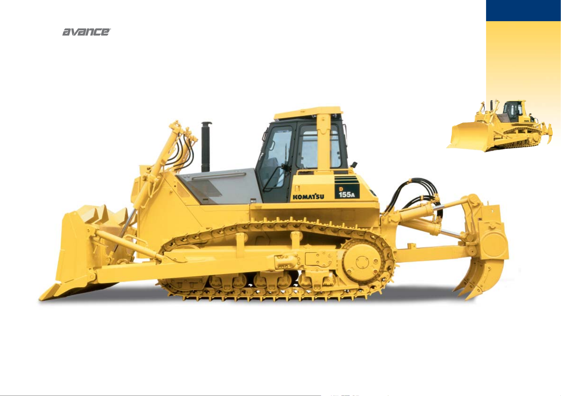
CRAWLER DOZER
D155A-5
D
155A
www.Komatsu.com Printed in Japan 200803 IP. AD (05)
CEN00003-02 Materials and specifications are subject to change without notice
is a trademark of Komatsu Ltd. Japan
Page 2
2 3
FLYWHEEL HORSEPOWER
225 kW 302 HP @ 1900 rpm
OPERATING WEIGHT
38700 kg 85,320 lb
BLADE CAPACITY
Semi-U: 8.8 m311.5 yd
3
Full-U: 11.8 m315.4 yd
3
The entirely new Komatsu D155A-5
carries on the tradition
of excellence established by the highly
regarded D155A-3.
A Komatsu-designed
resilient equalized
undercarriage (REU). Unique X-type bogies
provide tremendous traction on uneven ground.
Improves traction component durability and
operator comfort. See page 6.
Wet type multiple-disc
steering clutches/brakes
eliminate both clutch and brake
adjustment for facilitating maintenance.
See page 5.
Modular power train for increased
serviceability and durability. Forward
mounted pivot shafts isolate final drives
from blade loads. See page 8.
D155A-5 Crawler Dozer
Blade tilt lines
completely protected.
Komatsu Torqflow transmission offers
single lever control of speed (3 forward
and 3 reverse) and directional changes. See page 4.
Easy to learn and easy to operate
left hand joystick
controls all tractor motion, while right hand joystick
controls all blade functions for accurate grading and high
productivity. See pages 4 and 5.
W
ALK
-A
ROUND
W
ALK
-A
ROUND
D155A-5
CRAWLER DOZER
Komatsu torque converter
reduces shocks for
smooth operation. See page 9.
Reduced maintenance with
hydraulic reservoir sight gauge
and spin-off filters housed in
compartment. Gull wing engine side
doors for easy and safer engine servicing. (See
other reduced maintenance features on page 8.)
Photos may include optional equipment
Page 3

5
All steering, direction, and speed changes
can be made with a single joystick control.
When the operator wants to move the machine forward and to the left, he simply moves the
joystick forward and to the left. When he desires a gear change, he merely twists his wrist.
The machine responds to the movement of the lever, providing the operator with feeling of
natural control with Komatsu joystick.
Low-Noise Design
The engine, power train components, and
control valves are rubber-mounted to the
frame. A low-noise engine used and a
radiator mask which diverts the engine noise.
Engine side covers provide more than style
by damping engine noise.
Easy-to-Operate Work Equipment
Control Lever
● A PPC valve is used with the right joystick
blade control. This improves operator com-
fort because of reduced operating effort
and stroke.
● With the Closed-Center Load Sensing
(CLSS) hydraulic system, blade lever
stroke is directly proportional with blade
speed, regardless of the load and travel
speed. This results in superb, fine controll-
ability.
Hexagonal Pressurized Cab
(Optional)
Air filters and a higher internal air pressure
combine to prevent external dust from enter-
ing the cab. The cab’s hexagonal design pro-
vides excellent front, side, and rear visibility.
The REU and the oil damper mount cab
soften shock for operator comfort and extend
components life.
Operator’s Compartment
4
D155A-5
CRAWLER DOZER
Electronic Monitor Panel
An electronic monitoring system prevents minor problems from developing into major ones.
All meters and gauges are controlled by a microcomputer, which provides a wide indication
range for easier, more precise reading.
● Electrical Charge Lamp
● Engine Air Intake Pre-heat Lamp
● Engine Coolant Temperature Caution Lamp
● Engine Coolant Temperature Gauge
● Engine Oil Pressure Caution Lamp
● Fuel Gauge
● Service Meter
● Monitor Caution Cancel Switch
● Monitor Caution Lamp
● Transmission Oil Temperature Gauge
Steering Functions
Forward and
reverse
Right and left
steering
First, to second,
to third shifting
Left Hand Right Hand
Ripper Functions
Forward
and rearward
Raise and
lower
Blade Functions
Lifting and
lowering
Tilting
O
PERATOR
’
S
C
OMPARTMENT
O
PERATOR
’
S
C
OMPARTMENT
Photo may include optional equipment
Wet type multiple-disc steering
clutches/brakes
Wet type multiple-disc type steering clutches are controlled by left hand single-lever joystick.
Steering clutches are spring loaded and hydraulically released, eliminating clutch adjustment
for maintenance-free operation. Wet multiple-disc steering brakes are spring loaded and
hydraulically released, and interconnected with steering clutches for steep turn. Steering
brakes also function as service brakes with pedal operation.
Photo may include optional equipment
Photo may include optional equipment
Page 4

6
Undercarriage
Advanced Resilient Equalized
Undercarriage (REU)
The Komatsu X-type bogie resilient
equalized undercarriage (REU) performs
independent see-saw movements. Tremen-
dous traction can be achieved even on
uneven ground, because the shoe always
follows the contour of the ground.
Arubber shock absorber is mounted on the
X-type bogie and decreases vibration and
shock. This X-bogie and rubber cushion
provide different absorption characteristics,
depending on the ground surface. When the
machine travels on flat ground, the REU
functions as a conventional rigid under-
carriage. When the machine travels on
uneven ground, the REU maximizes the
suspension effect. The Komatsu REU
system improves traction, component
durability, and operator comfort.
Conventional Undercarriage
There is minimal shoe slippage with the
conventional low drive type undercarriage.
The shoe slip limit has been substantially
raised due to long tracks and large ground
contact area. The large traction force thus
obtained, in combination with high engine
power, results in superb drawbar pull. With
the low center of gravity, dynamic stability
is excellent.
D155A-5
CRAWLER DOZER
Flexibility
Flexibly grasps ground surface due to Komatsu’s unique track-
roller design for more and better ground contact.
● Independent X-bogies and rubber pads (cushions) are
incorporated into the track rollers.
Powerful Drawbar Pull for All Kinds of Terrain
The X-bogie and rubber pad provide different suspension
characteristics depending on the ground surface. On flat
ground, REU functions as a conventional rigid undercarriage.
On uneven terrain, the REU maximizes the suspension effect
the shoes always follow the contour of the ground, ensuring
a greater actual ground contact for greatly-improved
drawbar pull.
Frame
Flat Bottom Frame
The pivot shafts and monocoque frames prevent mud build-
up. The design facilitates good maneuverability in muddy
conditions and reduces the chance of hanging up on stumps
or boulders.
On flat ground
On uneven ground
Ensures almost the same traction force as
a conventional rigid undercarriage.
Functions as a conventional rigid
undercarriage.
Track frame
Compared with a rigid type, the actual ground contact
area increases and powerful drawbar pull is ensured
because the track shoes follow the contour of the
ground. Large deformation of the rubber pads
contributes to greater suspension effect.
Seesaw movement is performed
corresponding to ground surface.
Comfortable Ride on Uneven Ground Minimum Shock in Riding Over Obstacles
On uneven ground, the rubber pad provides four times the
suspension effect.
When riding over obstacles, the height of the machine fall is low.
Flat ground travel
Suspension effect
Rough terrain travel
1
4
Obstacle height B
Fall height A
Conventional
rigid type
REU
A
B
7
U
NDERCARRIAGE
AND
F
RAME
U
NDERCARRIAGE
AND
F
RAME
Outer
bogie
Center
Shaft:
Fixed to track
frame
Track
roller
Rubber
pad
Inner
bogie
Page 5

STEERING
Joystick controls for all directional movements. Simply tilt the joystick
to the left to make a left turn. Tilt it to the right for a right turn.
Pushing the lever forward results in the machine forwarding, while
pulling it toward the operator reverses the machine. Gear shifting
also possible with the single-steering lever.
Wet, multiple-disc steering are spring-loaded hydraulically released.
Wet, multiple-disc, pedal-controlled service brakes are springactuated and hydraulically released. Gearshift lock lever also applies
service brakes.
Minimum turning radius. . . . . . . . . . . . . . . . . . . . . . . . . . 3.7 m 12'2"
(As measured by track marks on ground.)
UNDERCARRIAGE
Suspension. . . . . . . . . . . . . . . . . . Oscillation-type with equalizer bar
and forward mounted pivot shafts
Tr ack roller frame. . . . . . . . . . . . . . . . . . . . Monocoque, high-tensile-
strength steel construction
Lubricated track rollers are resiliently mounted to roller frame
through a series of exclusive X-type bogies whose oscillating
motion is cushioned by rubber pads.
Number of track rollers (each side) . . . . . . . . . . . . . . . . . . . . . . . . . 6
Number of carrier rollers (each side) . . . . . . . . . . . . . . . . . . . . . . . . 2
Lubricated tracks. Unique dust seals for preventing entry of foreign
abrasives into pin-to-bushing clearance for extended service. Track
tension easily adjusted with grease gun.
Number of shoes (each side) . . . . . . . . . . . . . . . . . . . . . . . . . . . . 41
Grouser height . . . . . . . . . . . . . . . . . . . . . . . . . . . . . . . . 80 mm 3.1"
Shoe width (standard/maximum) . . . . . . . . 560 mm 22"/710 mm 28"
Ground contact area . . . . . . . . . . . . . . . . . . . . . 35950 cm25,572 in
2
Ground pressure (tractor only) . . . . . . 76.5 kPa 0.78 kg/cm211.1psi
Gauge. . . . . . . . . . . . . . . . . . . . . . . . . . . . . . . . . . . . 2100 mm 6'11"
COOLANT AND LUBRICANT
CAPACITY (
REFILLING)
Coolant. . . . . . . . . . . . . . . . . . . . . . . . . . . . . . . 99 ltr 26.2 U.S. gal
Fuel tank . . . . . . . . . . . . . . . . . . . . . . . . . . . . 500 ltr 132.1 U.S. gal
Engine oil . . . . . . . . . . . . . . . . . . . . . . . . . . . . .
37 ltr 9.8 U.S. gal
Damper . . . . . . . . . . . . . . . . . . . . . . . . . . . . . .
1.5 ltr 0.4 U.S. gal
Tr ansmission, bevel gear
and steering system . . . . . . . . . . . . . . . . . . .
60 ltr 15.9 U.S. gal
Final drive (each side). . . . . . . . . . . . . . . . . . . .
58 ltr 15.3 U.S. gal
OPERATING WEIGHT (APPROXIMATE)
Tractor weight:
Including rated capacity of lubricant, coolant, full fuel tank, operator
and standard equipment . . . . . . . . . . . . . . . . . . .
27900 kg 61,510 lb
Above equipment plus optional side covers, air conditioner and 560 mm
22" extreme service shoes . . . . . . . . . . . . . . . . .
28600 kg 63,050 lb
Operating weight: Including Semi-U tiltdozer, multi-shank ripper,
steel cab, ROPS, operator, standard equipment, rated lubricant,
coolant full fuel tank, optional engine side covers, air conditioner and
560 mm 22” extreme service shoes . . . . . . . . . . 38700 kg 85,320 lb
Ground pressure . . . . . . . . . . . . . . . 105.9 kPa 1.08 kg/cm215.4 psi
Fuel Efficient Engine
The field-proven, rugged reliable Komatsu
225 kW 302 HP SA6D140E-2 provides high
torque for efficient dozing power and high
reliability and low fuel consumption.
Automatic Preheating Mechanism
The best preheating times is set
automatically by sensing ambient temp-
erature. This simplifies the preheating
operation.
Modular Power Train Components
Modular design has facilitated removal/
installation of power train components,
shortening machine downtime.
Wet, Multiple-Disc Brakes
Eliminate brake adjustments for
maintenance-free operation.
Various Features for
Easy Maintenance
● Radiator reserve tank
● Gull-wing engine side doors
● Centralized oil pressure test ports
● Centralized filter arrangement
Engine
9
D155A-5
CRAWLER DOZER
8
FINAL DRIVE
Double-reduction, spur and planetary final drives increase tractive
effort. Segmented sprockets are bolt-on for easy in-the-field
replacement.
D155A-5
Power Shift
DRAWBAR PULL VS. SPEED.
MAXIMUM USABLE PULL
DEPENDS ON TRACTION AND
WEIGHT OF TRACTOR INCLUDING
MOUNTED EQUIPMENT.
Travel speed Forward Reverse
1st 0–3.7 km/h 0–2.3 mph 0–5.0 km/h 0–3.1 mph
2nd 0–6.7 km/h 0–4.2 mph 0–8.2 km/h 0–5.1 mph
3rd 0–11.0 km/h 0–6.8 mph 0–13.9 km/h 0–8.6 mph
S
PECIFICATIONS
S
PECIFICATIONS
E
NGINE AND
T
ORQUE
C
ONVERTER
E
NGINE AND
T
ORQUE
C
ONVERTER
ENGINE
Komatsu SA6D140E-2, water-cooled, 4-cycle, turbocharged and
aftercooled, diesel engine, 6 cylinders with 140 mm 5.51" bore x
165 mm 6.50" stroke and 15.24 ltr 930 in3piston displacement.
Flywheel horsepower*:
SAE J1349. . . . . . . . . . . . . . . . . . . . 225 kW 302 HP at 1900 rpm
DIN 6270 . . . . . . . . . . . . . . . . . . . . . 225 kW 305 PS at 1900 rpm
Maximum torque. . . . . . . . . . . . . . 160 kg•m 1,157 lb/ft @ 1250 rpm
* Net flywheel horsepower output for standard engine (SAE J1349)
including air cleaner, alternator (not charging), water pump, lubricating
oil pump, fuel pump, muffler, and fan.
Direct-injection fuel system. All-speed mechanical governor.
Forced lubrication driven by gear pump. Full-flow filter for lube
oil purification. Dual element, dry-type air filters with automatic
dust ejector and dust indicator. 24 V/11 kW electrical starting
motor. 24 V/35A alternator. 2 x 12 V/170 Ah batteries.
TORQFLOW TRANSMISSION
Komatsu’s TORQFLOW transmission consists of a water-cooled,
3-element, 1-stage, 1-phase torque converter and a planetary gear,
multiple-disc clutch transmission which is hydraulically actuated
and force-lubricated for optimum heat dissipation. Joystick control
of gears (3 forward and 3 reverse) and directional steering changes.
Gearshift lock lever and neutral safety switch prevent machine from
accidental starts.
Photo may include optional equipment
1000 kgf
1000 lb
160
70
140
60
120
50
100
40
80
DRAWBAR PULL
30
60
20
40
10
20
0
0
F1
F2
F3
20 4681012 14 km/h
kN
600
500
400
300
200
100
MPH20 4 68
TRAVEL SPEED
Page 6

11
D155A-5
CRAWLER DOZER
10
Overall length Blade Blade Maximum lift Maximum drop Maximum tilt Additional
with dozer capacity* length x height above ground below ground adjustment weight
Semi-U 6300 mm 8.8 m
3
3955 mm x 1720 mm 1250 mm 590 mm 1000 mm 4900 kg
Tilt Dozer 20'8" 11.5 yd
3
13' x 5'8" 4'1" 1'11" 3'3" 10,800 lb
Full-U 6695 mm 11.8 m34265 mm x 1760 mm 1250 mm 590 mm 1080 mm 5600 kg
Tilt Dozer 22' 15.4 yd
3
14' x 5'9" 4'1" 1'11" 3'7" 12,350 lb
Angle 6502 mm 4.9 m
3
4850 mm x 1205 mm 1295 mm 745 mm 520 mm 5140 kg
Tilt Dozer 21'4" 6.4 yd
3
15'11" x 3'11" 4'3" 2'5" 1'8" 11,330 lb
Number of cylinders Bore
Blade Lift 2 120 mm 4.72"
Blade Tilt 1 180 mm 7.09"
Ripper Lift 2 160 mm 6.30"
Ripper Tilt 2 160 mm 6.30"
DOZER EQUIPMENT
HYDRAULIC SYSTEM
Closed-center load sensing system (CLSS) designed for precise and
responsive control, and for efficient simultaneous operation.
Hydraulic control unit:
All spool control valves externally mounted beside the hydraulic tank.
Gear-type hydraulic pump with capacity (discharge flow) of 255 ltr
67.4 U.S. gal/min at rated engine rpm.
Relief valve setting. . . . . . . . . . . . . . 20.6 MPa 210 kg/cm22,990 psi
Control valves:
Spool control valve for Semi-U tilt dozer and Full-U tilt dozer.
Positions:
Blade lift. . . . . . . . . . . . . . . . . . . . . . . Raise, hold, lower, and float
Blade tilt . . . . . . . . . . . . . . . . . . . . . . . . . . . . . Right, hold, and left
Additional control valve required for variable digging angle
multi-shank ripper and giant ripper.
Positions:
Ripper lift . . . . . . . . . . . . . . . . . . . . . . . . . . Raise, hold, and lower
Ripper tilt . . . . . . . . . . . . . . . . . . . . . Increase, hold, and decrease
Hydraulic cylinders . . . . . . . . . . . . . . . . . . . . Double-acting, piston
Hydraulic oil capacity (refilling):
Semi-U tilt dozer . . . . . . . . . . . . . . . . . . . . . . . . 97 ltr 25.6 U.S. gal
U-tilt dozer . . . . . . . . . . . . . . . . . . . . . . . . . . . . 97 ltr 25.6 U.S. gal
Multi-shank ripper (additional volume). . . . . . . . 35 ltr 9.2 U.S. gal
Giant ripper (additional volume) . . . . . . . . . . . . 35 ltr 9.2 U.S. gal
Use of high-tensile-strength steel in moldboard for strengthened blade construction. Blade tilt hose piping is mounted inside the dozer
push arm to protect from damage.
DIMENSIONS (SEMI-U TILT DOZER)
STANDARD EQUIPMENT
A 3955 mm 13'0"
B 2080 mm 6'10"
C 2260 mm 7'5"
D 2695 mm 8'10"
E 3500 mm 11'6"
F 925 mm 3'0"
G 870 mm 2'10"
H 2510 mm 8'3"
I 3210 mm 10'6"
J 8155 mm 26'9"
K 4975 mm 16'4"
OPTIONAL EQUIPMENT
ROPS CANOPY
● Additional weight 505 kg 1,110 lb
● Meets ISO 3471, SAE J1040 APR88, and ISO 3449
FOPS standards.
● Roof dimensions:
—Length: 1275 mm 4'2"
—Width: 1500 mm 4'11"
—Height from operator compartment floor: 1757 mm 5'9"
STEEL CAB
● Additional weight: 285 kg 630 lb
● All-weather, enclosed pressurized cab.
● Roof dimensions:
—Length: 1765 mm 5'9"
—Width: 1720 mm 5'8"
—Height from floor to ceiling: 1515 mm 5'
VARIABLE MULTI-SHANK RIPPER
● Additional weight (including hydraulic control unit):
3710 kg 8,180 lb
● Beam length: 2260 mm 7'5"
● Hydraulically-controlled parallelogram-type ripper with
three shanks. Digging angle steplessly adjustable
● Maximum digging depth: 870 mm 2'10"
● Maximum lift above ground: 925 mm 3'
● Standard digging angle*: 49°
VARIABLE GIANT RIPPER
● Additional weight (including hydraulic control unit):
2760 kg 6,080 lb
● Beam length: 1535 mm 5'
● Hydraulically-controlled parallelogram-type ripper with one shank.
Digging angle steplessly adjustable
● Maximum digging depth: 1220 mm 4'
● Maximum lift above ground: 925 mm 3'
● Standard digging angle*: 49°
* Measured with ripper point on ground and shank is vertical
SHOES
OTHER
● Air conditioner
● Backup alarm
● Cab heater and defroster
● Engine side cover
● Locks, filler caps and covers
● Hinged, strengthened radiator mask
● Reversible fan
● Rigid drawbar
● Seat belt
● Tool kit and ordinary spare parts
Shoes (optional) Additional weight Ground contact area
560 mm 22" single
grouser shoes 0 kg 0 lb 35950 cm25,572 in
2
610 mm 24" single
grouser shoes +210 kg +460 lb 39160 cm26,070 in
2
660 mm 26" single
grouser shoes +400 kg +880 lb 42370 cm26,567 in
2
710 mm 28" single
grouser shoes +620 kg +1,370 lb 45580 cm27,056 in
2
560 mm 22" extreme
service shoes +460 kg +1,010 lb 35950 cm25,572 in
2
610 mm 24" extreme
service shoes +700 kg +1,540 lb 39160 cm26,070 in
2
660 mm 26" extreme
service shoes +940 kg +2,070 lb 42370 cm26,567 in
2
● Air cleaner, double element with
dust indicator
● Alternator, 35 ampere
● Batteries, 2 x 12V/170 Ah
● Blower cooling fan
● Bogie roller guards
● Decelerator pedal
● Electronic instrument monitor panel
● Fenders
● Horn, warning
● Hydraulics for dozer
● Lighting system, (includes 2 front, 1 rear)
● Mono-lever steering control
● Muffler with rain cap
● Radiator reserve tank
● Rear cover
● ROPS mounting brackets
● Suspension seat
● Starting motor, 11 kW/24V
● Tr ack roller guard, end sections
● Tr ack shoe assembly
—Sealed and lubricated track
● 560 mm 22" single grouser shoe
● Underguards, oil pan and transmission
*Blade capacity is based on the SAE recommended practice J1265
Ground Clearance:
485 mm 1'7"
 Loading...