

Kollmorgen Seidel 6SM 45M-3000, 6SM45 Series, 6SM 45L-3000, 6SM 56S-3000, 6SM 56M-3000 Technical Description
...Page 1
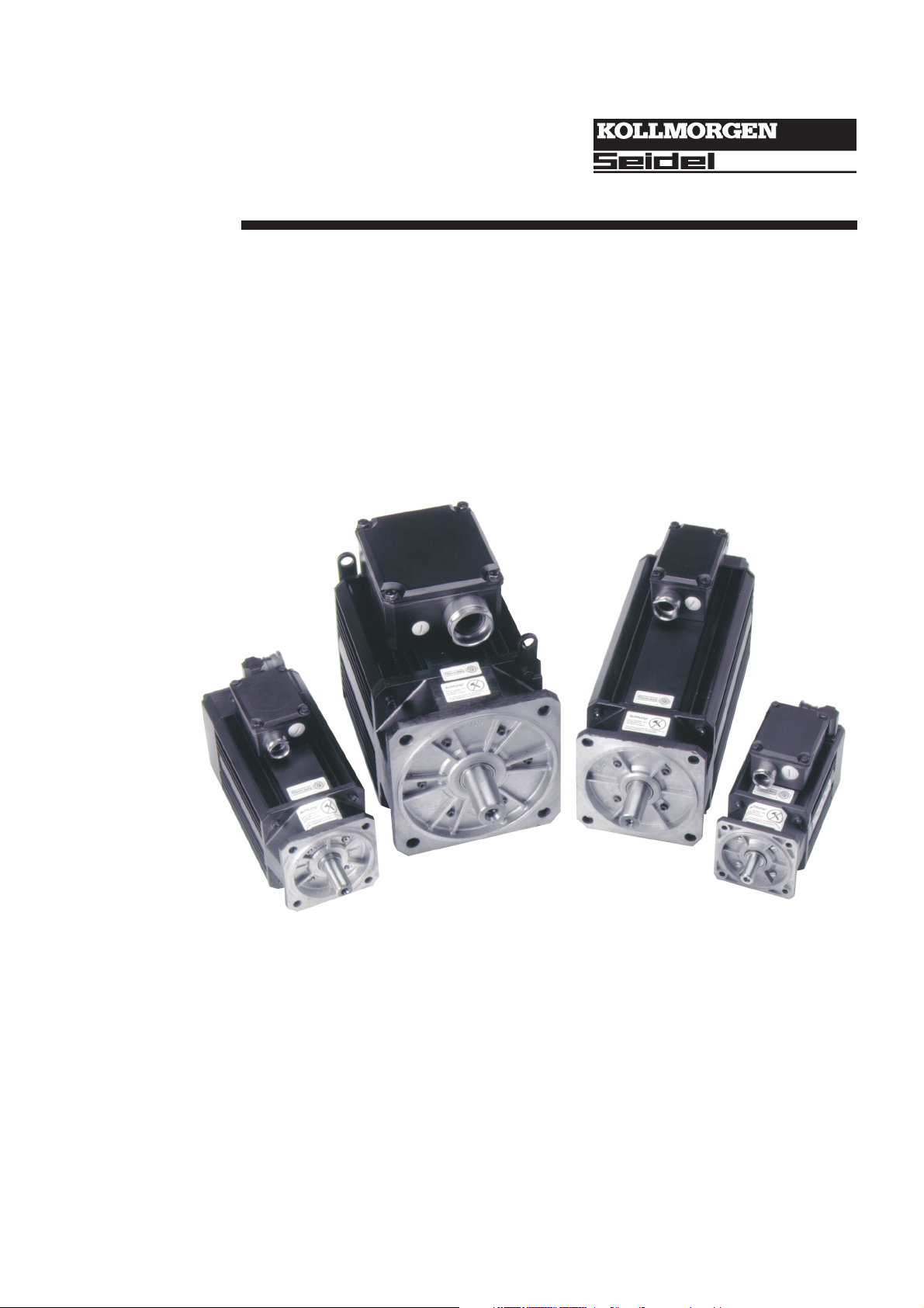
Synchronous Servomotors
Series 6SM45..100
Technical description, Installation, Commissioning
Edition 05/2000
Page 2
Already published editions
Edition Comment
07 / 93 First edition
10 / 94 Adaptation to modified technical design, layout and page numbering changed
05 / 96 New motors 6SM27 / 6SM37 / 6SM100
05 / 97 New motors 6SMx7, 6SM109, several corrections
03 / 98 6SM27..77/109 removed
05 / 2000 Enhanced torque characteristics, new layout, corrections
Technical changes to improve the performance of the equipment
may be made without prior notice!
Printed in the Federal Republic of Germany 05/2000
Mat.No.: 79797
All rights reserved. No part of this work may be reproduced in any form (by printing, photocopying,
microfilm or any other method) or stored, processed, copied or distributed by electronic means
without the written permission of Seidel Corporation.
Page 3

Kollmorgen 05.2000 Contents
Contents Drawing Page
Contents...............................................................................3
Safety Notes...........................................................................5
Important Notes.......................................................................6
Manufacturer Declaration ............................................................7
I General
I.1 About this manual ........................................................................9
I.2 Prescribed usage ........................................................................9
I.3 Design of the motors.....................................................................10
I.4 General technical data ...................................................................10
I.5 Standard features .......................................................................11
I.5.1 Style ............................................................................11
I.5.2 Shaft end, A-side ..................................................................11
I.5.3 Flange ...........................................................................11
I.5.4 Protection class....................................................................11
I.5.5 Protective device...................................................................11
I.5.6 Insulation material class .............................................................12
I.5.7 Vibration class.....................................................................12
I.5.8 Connection method.................................................................12
I.5.9 Resolver .........................................................................12
I.5.10 Holding brake .....................................................................12
I.6 Selection criteria ........................................................................12
I.7 Options ...............................................................................13
I.8 Nameplate.............................................................................13
I.9 Technical data..........................................................................14
I.9.1 Definitions ........................................................................14
I.9.2 Technical data 6SM45..100 ..........................................................15
I.9.3 Technical data 6SM56..100-BV .......................................................16
II Installation / Commissioning
II.1 Important notes .........................................................................17
II.2 Assembly / Wiring .......................................................................18
II.2.1 Connection methods ................................................................20
II.3 Commissioning .........................................................................21
- E.4.929.4/09
- A.4.031.1/35
Motor series 6SM45..100 3
Page 4

Contents 05.2000 Kollmorgen
III Drawings
III.1 Non-ventilated motors....................................................................23
III.1.1 Dimensions 6SM45..100.............................................................23
III.1.2 Radial-/axial force at the shaft end .....................................................23
III.1.3 Wiring diagram 6SM45..100 ..........................................................24- A.4.017.4/10
III.1.4 Torque characteristics 6SM45S-3000...................................................25
III.1.5 Torque characteristics 6SM45M-3000 ..................................................25
III.1.6 Torque characteristics 6SM45L-3000 ...................................................26
III.1.7 Torque characteristics 6SM56S-3000...................................................26
III.1.8 Torque characteristics 6SM56M-3000 ..................................................27
III.1.9 Torque characteristics 6SM56L-3000 ...................................................27
III.1.10 Torque characteristics 6SM71K-3000...................................................28
III.1.11 Torque characteristics 6SM71S-3000...................................................28
III.1.12 Torque characteristics 6SM71M-3000 ..................................................29
III.1.13 Torque characteristics 6SM100K-3000..................................................29
III.1.14 Torque characteristics 6SM100S-3000..................................................30
III.1.15 Torque characteristics 6SM100M-3000 .................................................30
III.1.16 Torque characteristics 6SM100L-3000 ..................................................31- A.4.036.3/17
III.2 Ventilated motors .......................................................................32
III.2.1 Dimensions 6SM56..100-BV..........................................................32
III.2.2 Radial-/axial force at the shaft end .....................................................32
III.2.3 Wiring diagram 6SM56..100-BV .......................................................33- A.4.017.4/11
III.2.4 Fan connection ....................................................................34.- A.4.029.4/07
III.2.5 Torque characteristics 6SM56S-3000-BV................................................35
III.2.6 Torque characteristics 6SM56M-3000-BV ...............................................35
III.2.7 Torque characteristics 6SM56L-3000-BV ................................................36
III.2.8 Torque characteristics 6SM71K-3000-BV................................................36
III.2.9 Torque characteristics 6SM71S-3000-BV................................................37
III.2.10 Torque characteristics 6SM71M-3000-BV ...............................................37
III.2.11 Torque characteristics 6SM100K-3000-BV...............................................38
III.2.12 Torque characteristics 6SM100S-3000-BV...............................................38
III.2.13 Torque characteristics 6SM100M-3000-BV ..............................................39
III.2.14 Torque characteristics 6SM100L-3000-BV ...............................................39
IV Appendix
IV.1 Delivery package, transport, storage, maintenance, disposal......................................41
IV.2 Fault-finding ...........................................................................42
IV.3 Index .................................................................................43
- A.4.017.3/04, 4/20
- A.4.036.3/13, 21
- A.4.036.3/14, 22
- A.4.036.3/51, 52
- A.4.036.3/15, 53
- A.4.036.3/16, 50
- A.4.036.3/18, 19
. .A.4.017.3/09, 4/21
- A.4.036.3/51, 54
- A.4.036.3/56, 57
- A.4.036.3/58, 59
- A.4.036.3/60, 61
- A.4.036.3/62, 63
4 Motor series 6SM45..100
Page 5
Kollmorgen 05.2000 Safety notes
Safety Notes
l
Only properly qualified personnel are permitted to perform such tasks as transport,
assembly, commissioning and maintenance. Properly qualified personnel are
persons who are familiar with the transport, assembly, installation, commissioning
and operation of motors, and who have the appropriate qualifications for their jobs.
The qualified personnel must know and observe the following standards and
regulations:
IEC 364 resp. CENELEC HD 384 or DIN VDE 0100
IEC-report 664 or DIN VDE 0110
national regulations for safety and accident prevention or BGV A2
l
l
l
l
l
Read the available documentation before assembly and commissioning. Incorrect
handling of the motors can result in injury and damage to persons and machinery.
Keep strictly to the technical data and the information on the connection
requirements (nameplate and documentation).
It is vital that you ensure that the motor housing is safely earthed to the PE
(protective earth) busbar in the switch cabinet. Electrical safety is impossible
without a low-resistance earth connection.
Never open the motor terminal box during operation. Do not unplug any
connectors during operation. This creates the danger of death, severe injury, or
extensive material damage.
Power connections may be live even when the motor is not rotating. Never
disconnect the power connections of the motor while the equipment is energised.
This can cause flashovers with resulting injuries to persons and damage to the
contacts.
After disconnecting the servo-amplifier from the supply voltage, wait at least five
minutes before touching any components which are normally live (e.g. contacts,
screw connections) or opening any connections.
The capacitors in the servo-amplifier can still carry a dangerous voltage up to five
minutes after switching off the supply voltages. To be quite safe, measure the
DC-link voltage and wait until the voltage has fallen below 40V.
l
The surfaces of the motors can be very hot in operation, according to their
protection category. The surface temperature can reach 100°C. Measure the
temperature, and wait until the motor has cooled down below 40°C before touching
it.
Warning signs used in this manual:
Danger to personnel from electricity
and its effects
see chapter (cross reference)
Þ
General warning
general instruction
mechanical hazard
special emphasis
●
Motor series 6SM45..100 5
Page 6
Important notes 05.2000 Kollmorgen
Important Notes
l
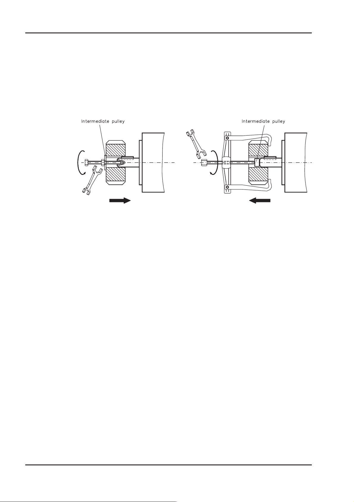
l
Servomotors are precision equipment. The flange and shaft are especially
vulnerable during storage and assembly — so avoid brute force. Precision requires
delicacy. It is important to use the locking thread which is provided to tighten up
couplings, gear wheels or pulley wheels and warm up the drive components, where
possible. Blows or the use of force will lead to damage to the bearings and the
shaft.
Wherever possible, use only backlash-free, frictionally-locking collets or couplings,
e.g. from the manufacturers Baumann & Cie, Gerwah, Jacob, KTR or Ringspann.
Ensure correct alignment of the couplings. A displacement will cause unacceptable
vibration and the destruction of the bearings and the coupling.
l
l
l
l
l
For toothed belts, it is vital to observe the permissible radial forces. An excessive
radial load on the shaft will significantly shorten the life of the motor.
Avoid axial loads on the motor shaft, as far as possible. Axial loading significantly
shortens the life of the motor.
In all cases, do not create a mechanically constrained motor shaft mounting by
using a rigid coupling with additional external bearings (e.g. in a gearbox).
For mounting style V3 (shaft end upwards), make sure that no liquid can enter the
upper bearing.
Take note of the no. of motor poles and the no. of resolver poles, and ensure that
the correct setting is made in the servo-amplifier which is used. An incorrect
setting can lead to the destruction of the motor, especially with small motors.
6 Motor series 6SM45..100
Page 7

Kollmorgen 05.2000 Manufacturer Declaration
Manufacturer declaration
According to the EG-Machine-guideline 89/392/EWG, appendix II B
We, the company
Kollmorgen Seidel GmbH & Co. KG
Wacholderstraße 40-42
40489 Düsseldorf
declare, that the product
Motor series 6SM
(types 6SM45, 6SM56, 6SM71, 6SM100)
is intended exclusively, in its standard version, for installation in another machine and that its
commissioning is forbidden until it has been established that the machine into which this product is
to be installed conforms to the provisions of the EC Directive in its version 89/392/EEC.
We confirm that the above-mentioned product conforms to the following standards:
73/23/EWG Low voltage directive
VDE 0530 / DIN 57530 Provisions for rotating machinery
DIN 42950 Design
DIN 748 Cylindrical shaft ends
DIN 42955 True running, coaxiality and concentricity
DIN ISO 2373 Vibration class
Issued by: Management
Lawrence D. Kingsley
This Declaration does not contain any assurance of properties. The notes on safety and protection
in the operating instructions must always be observed.
Motor series 6SM45..100 7
Page 8

05.2000 Kollmorgen
This page has been deliberately left blank
8 Motor series 6SM45..100
Page 9
Kollmorgen 05.2000 General
I General
I.1 About this manual
This manual describes the 6SM45..100 series of synchronous servomotors (standard
version). Among other things, you find information about:
Description of the Motors, Technical Data Chapter I
l
l
Installation, Commissioning of the motors Chapter II
Dimensions, wiring and characteristics Chapter III
l
Notes on Transport, Storage, Maintenance, Disposal Chapter IV
l
This Manual is intended for the use of qualified staff with professional knowledge
of electrical and mechanical engineering.
The motors are operated in drive systems together with servo-amplifiers digifas® or
SERVOSTAR™. Please observe the entire system documentation, consisting of:
— Installation and commissioning instructions for the servo-amplifier
— Installation and commissioning instructions for any CONNECT module or expansion
— card which is connected
— Operating manual for the Operator Software of the servo-amplifier
— Technical description of the 6SM45..100 series of motors
I.2 Prescribed usage
The 6SM45..100 series of synchronous servomotors is designed especially for drives for
industrial robots, machine tools, textile and packing machinery and similar with high
requirements for dynamics.
The user is only permitted to operate the motors under the ambient conditions which are
defined in this documentation.
The 6SM45..100 series of motors is exclusively intended to be driven by servo-amplifi
ers from the digifas® or SERVOSTAR™ series under speed and / or torque control.
The mains supply voltage of the used servo amplifier must not exceed 400V at 50..60Hz,
TN-system or TT-system with earthed neutral point.
The motors are installed as components in electrical apparatus or machines and can only
be commissioned and put into operation as integral components of such apparatus or
machines.
The motors must never be connected directly to the mains supply.
The thermal contact which is integrated in the motor windings must be observed and
evaluated.
The conformity of the servo-system to the standards mentioned in the manufacturers
declaration on page 7 is only guaranteed when the components (servo-amplifier, motor,
cables etc.) that are used have been supplied by us.
-
Motor series 6SM45..100 9
Page 10

General 05.2000 Kollmorgen
I.3 Design of the motors
Synchronous servomotors in the 6SM45..100 series are brushless DC motors for
demanding servo applications. When combined with our digital servo-amplifiers they are
especially suited for positioning tasks in industrial robots, machine tools, transfer lines
etc. With high requirements for dynamics and stability.
The servomotors have permanent magnets in the rotor. The rare earth neodymium
-iron-boron magnetic material is an important factor in making it possible to drive these
motors in a highly dynamic fashion. A three-phase winding which is driven by the
servo-amplifier is integrated into the stator. The motor does not have any brushes since
commutation is performed electronically by the servo-amplifier.
For these motors, forced ventilation is usually not necessary, because of the optimised
heat transfer through the strongly ribbed motor housing. However, in order to increase
M
, the motors in the series 6SM56..100 can be delivered with a separately driven fan
0
(motor plus option -BV-). The fan can also be retrofitted.
The temperature of the winding is monitored by temperature sensors in the stator wind
ings and is signalled via an electrically isolated contact (normally closed).
A resolver is built into the motors as feedback element. The servo-amplifiers in the
digifas® or SERVOSTAR™ series evaluate the resolver (hence rotor) position and supply
sinusoidal currents to the motors.
The motors can be delivered with or without a built-in holding brake.
The motors are enamelled in matt black (RAL 9005). This finish is not resistant against
solvents (e.g. trichlorethylene, nitro-thinners, or similar).
I.4 General technical data
Climate category 3K3 to EN 50178
Ambient temperature 5...+40°C for site altitude up to 1000m amsl
(at rated values) It is vital to consult our applications department
Permissible humidity (at rated values) 85% rel. humidity, no condensation
Power derating 1% / K in range 40°C...50°C up to 1000m amsl
(currents and torques) for site altitude above 1000m amsl and 40°C
-
for ambient temperatures above 40°C and
encapsulated mounting of the motors.
6% up to 2000m amsl
17% up to 3000m amsl
30% up to 4000m amsl
55% up to 5000m amsl
No derating for site altitudes above 1000m amsl
with temperature reduction of 10K / 1000m
Max. permissible flange temperature 65°C ± 10% at rated values
Ball-bearing life ³ 20.000 operating hours
Technical data ÞI.9
Storage data ÞIV.1
10 Motor series 6SM45..100
Page 11
Kollmorgen 05.2000 - E.4.929.4/09 General
I.5 Standard features
I.5.1 Style
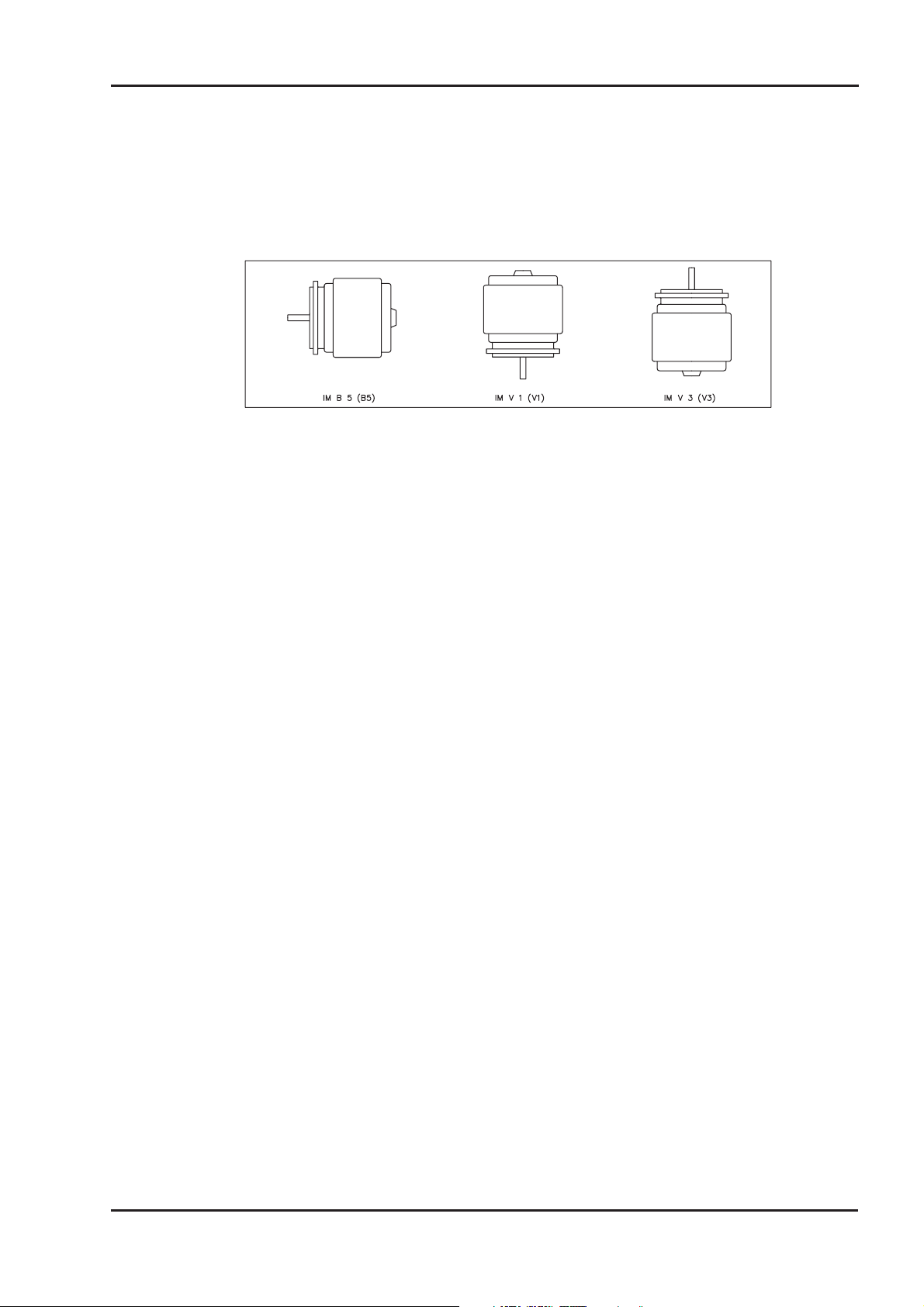
The basic style for the 6SM45..100 synchronous motors is style IM B5 according to
DIN42950. The permitted mounting positions may be read from the technical data of the
motor series.
I.5.2 Shaft end, A-side
Power transmission is made through the cylindrical shaft end A (fit k6) to DIN 748, with a
locking thread but without a fitted-keyway.
If the motors drive via pinions or toothed belts, then high radial forces will occur. The per
missible values at the end of the shaft may be read from the diagram in chapter III.1.2.
The maximum values at rated speed you will find at the technical data. Power take-off
from the middle of the free end of the shaft allows a 10% increase in F
The curves are based on a bearing life of 20.000 operating hours.
The axial force F
Double-coned collets have proved to be ideal zero-backlash coupling devices, combined,
if required, with metal bellows couplings.
I.5.3 Flange
Flange dimensions to IEC standard, fit j6, accuracy according to DIN 42955.
Tolerance class: N (R available as option -65-)
I.5.4 Protection class
Standard version IP65
Motors with separate fan (Option -BV-) IP54
Standard shaft bushing IP64
Shaft bushing with shaft-sealing ring (Option -J-) IP65
I.5.5 Protective device
must not exceed FR/3.
A
-
.
R
The standard version of each motor is fitted with a thermostat (electrically isolated,
normally closed). You will find the switching point at the technical data. The thermostat
does not provide any protection against short, heavy overloading. Provided that our pre
assembled resolver cable is used, the thermostat contact is integrated into the monitoring
system of the digital servo-amplifier digifas® or SERVOSTAR™.
The flange temperature must not exceed 65°C in rated operation.
-
Motor series 6SM45..100 11
Page 12
General 05.2000 - A.4.031.1/35 Kollmorgen
I.5.6 Insulation material class
The motors come up to insulation material class F according to DIN 57530.
I.5.7 Vibration class
The motors are made to vibration class N according to DIN ISO 2373.
I.5.8 Connection method
The motors are fitted with rectangular connectors for resolver signals and terminal boxes
for the power supply. The mating connectors are not part of the delivery package.
We can supply preassembled resolver and power cables (Þ II.2.1).
I.5.9 Resolver
The motors are equipped with two-pole hollow-shaft resolvers.
I.5.10 Holding brake
The motors are optionally available with a holding brake.
Type designation: 6SMxxx-xxxx-G
A permanent magnet brake (24V DC) is integrated into the G-motors. When this brake is
de-energized it blocks the rotor. The holding brakes are designed as standstill brakes
and are not suited for repeated operational braking. If the brake is released then the rotor
can be moved without a remanent torque, the operation is free from backlash!
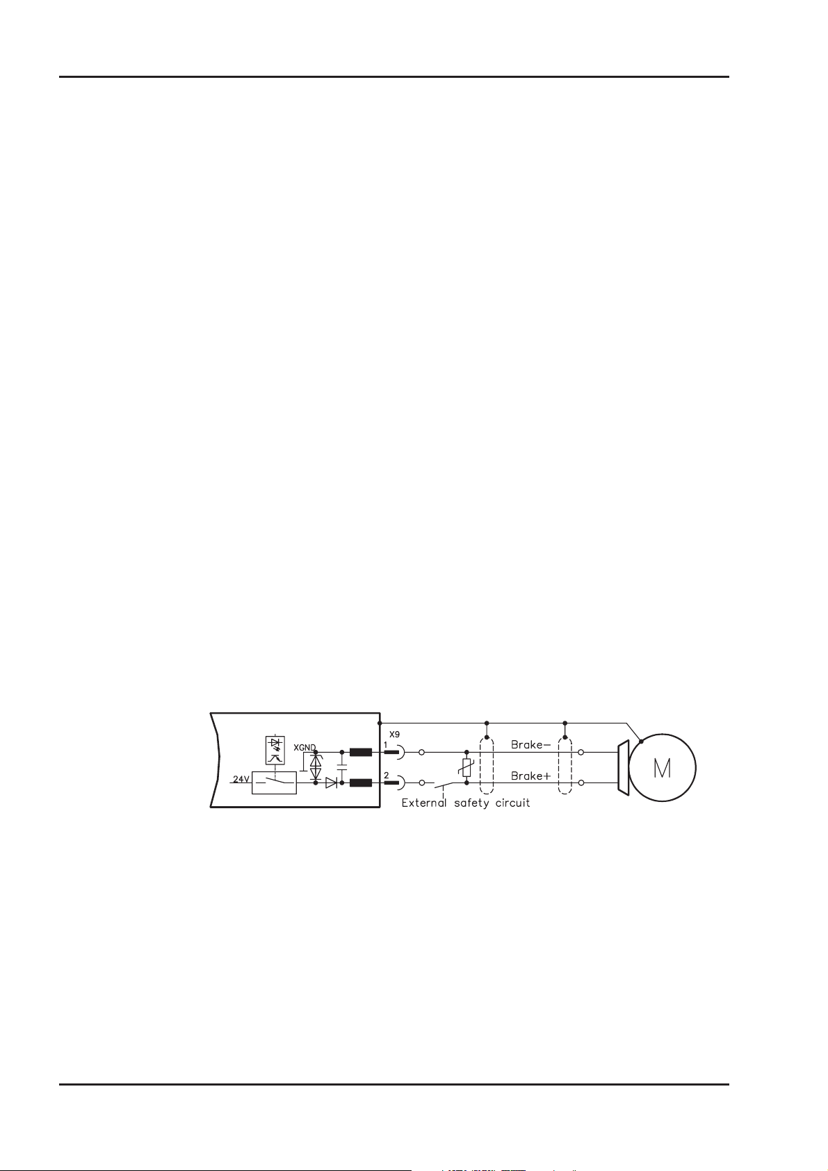
The holding brake can be controlled directly by digifas® or SERVOSTAR™-servo-ampli
fier (no personal safety !), the winding is suppressed in the servo-amplifier — additional
circuitry is not required.
If the holding brake is not controlled directly by the servo-amplifier, an additional wiring
(e.g. varistor) is required. Consult our applications department beforehand.
A personal safe operation of the holding brake requires an additional contact (normally
opened) in the braking circuit and an anti-surge-device (e.g. Varistor) for the brake.
-
Wiring example for SERVOSTAR™ 600:
SERVOSTAR™ 600
I.6 Selection criteria
The three-phase servomotors are designed to operate with digifas® or SERVOSTAR™
servo-amplifiers. Together, both units form a closed speed or torque control loop.
The most important selection criteria are:
— Standstill torque M
— Rated speed n
— Moment of inertia of motor and load J [kgcm²]
— Effective torque (calculated) M
When calculating the motors and servo-amplifiers which are required, take account of the
static load and the dynamic load (acceleration/braking). Collected formula and examples
of the calculations are available from our applications department.
n
0
rms
[Nm]
[min-1]
[Nm]
12 Motor series 6SM45..100
Page 13
Kollmorgen 05.2000 General
I.7 Options
-09- Special flanges and shafts are possible, we invite inquiries.
-G- Built-in holding brake.
-J- Radial shaft-sealing rings:
A radial shaft-sealing ring can be supplied at extra charge to seal against oil mist
and oil spray. This increases the protection rating of the shaft bushing to IP65. The
sealing ring is not suitable for dry running. When a holding brake is built in, the
motor length increases by option -J- for 10mm.
-65- Low tolerance for flange and shaft dimensions and increased concentricity and
angularity according to DIN 42955
-67- Shaft end precisely ground for oil tight seal,
tolerance field k5
-92- Tropical insulation
-BV- The rated torque in the series 6SM56..100 can be increased by fitting a separately
driven fan. The fan has the intake on the B-side, cools the motor surface and
exhausts to the A-side. For motors of the 6SM100 series, the fan is also obtainable
with a shortened bonnet.The electrical connection of the fan is carried out via a
connector. The mating connector is included in the delivery package of the option.
The protection rating of the motor with a fan is IP54.
-K- Mounting flange for Stöber bevel gear
-2K- Special varnish with 2-component enamel.
-426- Encoder adaptor for ROD426/ROQ425 with coupling and eccentric washers.
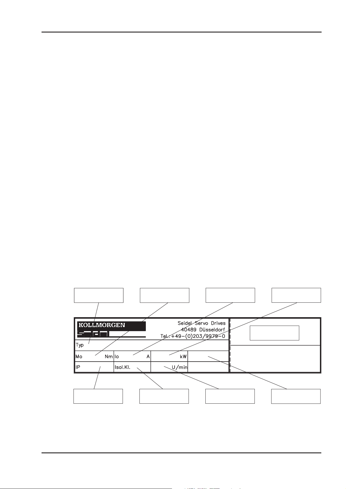
I.8 Nameplate
The nameplate depicted below is attached to the side of the servomotor. The information
described below is printed in the individual fields.
Servomotor-Type
and options
Standstill torque
Rated powerStandstill current
Serial number
Protection class
Insulation material
class
Rated speed Operating mode
Motor series 6SM45..100 13
Page 14

General 05.2000 Kollmorgen
I.9 Technical data
I.9.1 Definitions
Standstill torque M0[Nm]
The standstill torque can be maintained indefinitely at a speed n=0 min
ambient conditions.
-1
and rated
Rated torque M
[Nm]
n
The rated torque is produced when the motor is drawing the rated current at the rated
speed. The rated torque can be produced indefinitely at the rated speed in continuous
operation (S1).
Standstill current I
0rms
[A]
The standstill current is the effective sinusoidal current which the motor draws during
standstill to produce the standstill torque.
Rated current I
nrms
[A]
The rated current is the effective sinusoidal current which the motor draws at the rated
speed in order to produce the rated torque.
Peak current (pulse current) I
0max
[A]
The peak current (effective sinusoidal value) should not exceed 4-times the rated current.
The actual value is determined by the peak current of the servo-amplifier which is used.
Torque constant K
Trms
[Nm/A]
The torque constant defines how much torque in Nm is produced by the motor with 1A
r.m.s. current. The relationship is M=I x K
T
Voltage constant KE[V/1000min-1]
The voltage constant defines the induced motor EMF, as a sinusoidal peak value
between two terminals, per 1000 rpm
Rotor moment of inertia J [kgcm²]
The constant J is a measure of the acceleration capability of the motor. For instance, at I
the acceleration time tbfrom 0 to 3000 rpm is given as:
2
m
´´
ts
[]=
b
3000 2
Ms cm
´´ ´
0
p
60 10
J
42
´
with M
in Nm and J in kgcm²
0
0
Thermal time constant t
The constant t
defines the time for the cold motor, under a load of I0, to heat up to an
th
th
[min]
overtemperature of 0.63 x 10⁵ Kelvin. This temperature rise happens in a much shorter
time when the motor is loaded with the rated current.
Release delay time t
[ms] / Application delay time t
BRH
[ms] of the brake
BRL
These constants define the response times of the holding brake when operated with the
rated voltage from the digifas® or SERVOSTAR™ servo-amplifier.
14 Motor series 6SM45..100
Page 15
Kollmorgen 05.2000 General
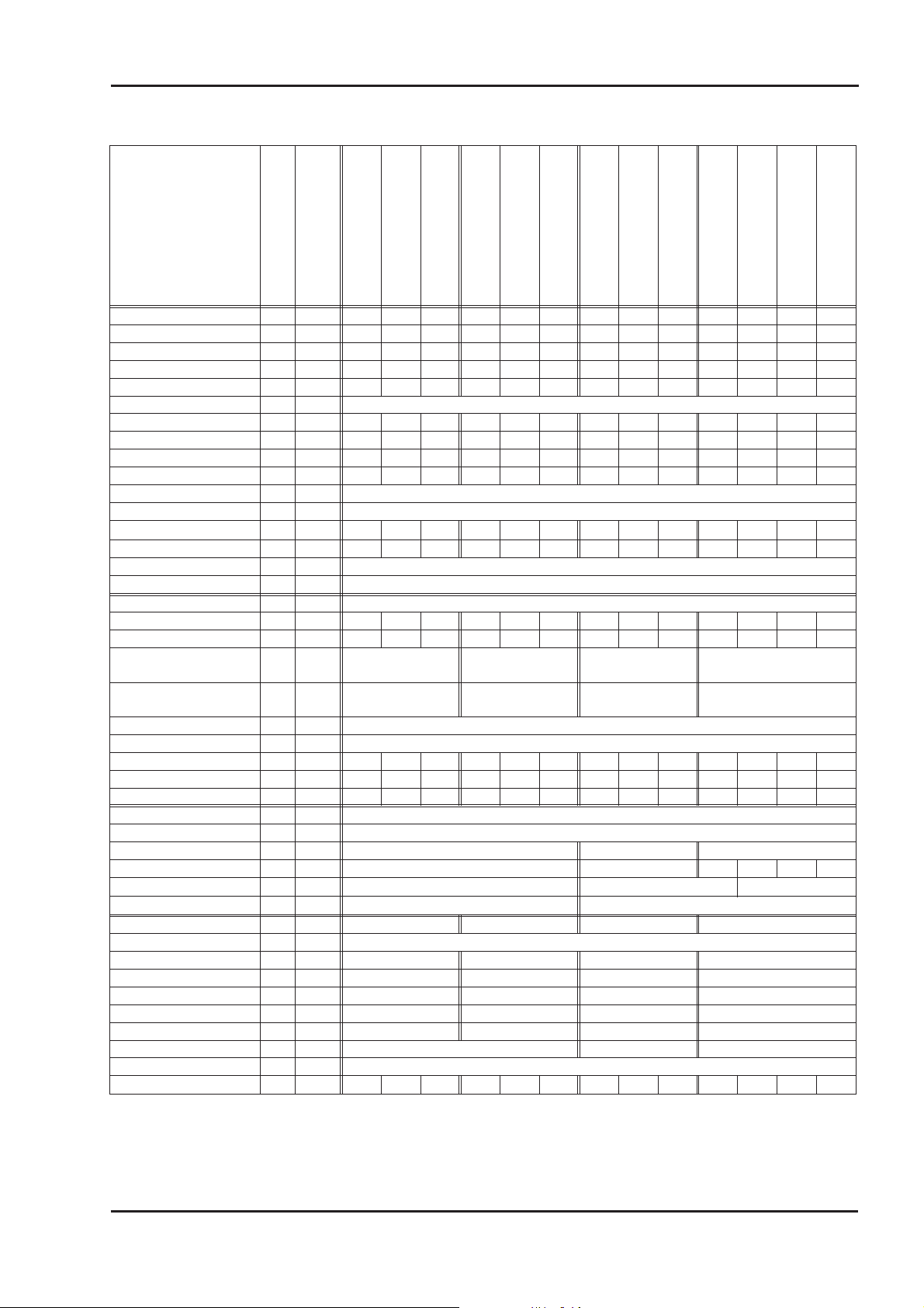
I.9.2 Technical data 6SM45..100
Data Sym Dim
6SM 45S-3000
6SM 45M-3000
6SM 45L-3000
6SM 56S-3000
6SM 56M-3000
6SM 56L-3000
6SM 71K-3000
6SM 71S-3000
6SM 71M-3000
6SM 100K-3000
6SM 100S-3000
6SM 100M-3000
Standstill torque M0Nm 0,85 1,7 3,2 3,8 7,0 10,0 10,5 16,5 22,0 25,0 36,0 46,0 57,0
Standstill current I
Rated speed n
Torque constant K
Voltage constant K
Mains supply voltage U
Rated torque at n
n
Rated current I
Rated power P
Peak current I
Motor pole no. p
Resolver pole no. p
Winding resistance Ph-Ph
A 1,3 1,3 2,4 2,8 4,8 7,6 8,0 12,3 15,6 18,8 26,7 35,0 42,0
0rms
min-13000 3000 3000 3000 3000 3000 3000 3000 3000 3000 3000 3000 3000
n
Nm/A 0,68 1,36 1,36 1,33 1,45 1,32 1,31 1,35 1,41 1,33 1,35 1,32 1,35
Trms
mVmin 58 116 116 114 124 113 112 115 121 114 116 113 115
E
V 400
n
MnNm 0,8 1,6 2,9 3,6 6,4 8,4 9,5 13,4 16,3 19,9 24,6 27,1 28,0
A 1,4 1,3 2,3 2,9 4,7 6,7 7,6 10,5 12,2 15,7 19,2 21,8 22,5
n
kW 0,25 0,5 0,91 1,13 2,0 2,6 3,0 4,2 5,1 6,2 7,7 8,5 8,8
n
A 4,7 5,6 9,6 12,4 19,6 28,3 32,0 44,0 51,0 72,0 113,0 150,0 180,0
0max
-6
Mot
-2
Res
R
20 W 25,4 34,0 11,9 9,4 4,0 1,8 1,65 0,8 0,57 0,46 0,22 0,16 0,12
Winding inductance Ph-Ph L mH 54,0 99,0 47,0 54,0 30,0 15,8 19,6 12,0 9,0 10,5 7,0 5,0 4,0
Insulation class - - F, DIN 57530
Switch point therm contact - °C 145 ± 5
Design - - IM B5 (V1, V3), DIN 42950
Rotor moment of inertia J kgcm² 1,5 2,1 3,4 5,2 10,0 15,0 20,0 31,0 42,0 74,0 108,0 141,0 175,0
Static friction torque M
Radial load permitted at
shaft end with n
n
Axial load permitted at
shaft end with n
n
Nm 0,127 0,131 0,14 0,154 0,18 0,208 0,23 0,28 0,334 0,4 0,49 0,58 0,67
R
F
R N 370 530 700 1050
F
A N 120 170 230 350
Tolerance class flange - - N, DIN42955
Vibration class - - N, DIN ISO 2373
Thermal time constant t
min 15 20 20 20 20 20 25 30 35 32 40 41 46
TH
Weight standard G kg 4,5 5,5 6,5 6,1 8,0 10,3 11,7 15,8 20,0 26,0 33,0 40,0 49,0
Order number standard - - 81681 81684 81752 81682 81683 81753 81679 81754 81680 84855 84856 84876 84874
EMV-RES connector - - 12 poles, round
RES cable, shielded - mm² 4x2x0,25
Power connection - stud M4 M6 M8
Motor cable, shielded - mm² 4x1 or 4x1,5 4x2,5 4x4 4x6 4x10 4x16
max. Æ of motor cable
-mm 15 20 28
max. Æ of braking cable - mm 8 12,5
Holding torque M
Operating voltage U
electrical power P
Moment of inertia J
Release delay time t
Application delay time t
Weight of the brake G
Nm 6,5 12 20 60
BR
V= 24 +6/-10%
BR
W161822 50
BR
kgcm² 1,06 3,6 9,5 57,5
BR
ms 10-30 30-60 20-60 70-160
BRH
ms 5-15 10-20 10-35 30-60
BRL
kg 0,6 1,1 1,9 5,4
BR
Motor cable with brake - mm² 4x1 + 2x0,75 or 4x1,5 + 2x0,75 4x2,5 + 2x1 Separate braking cable - mm² 4x1,5 or 4x2,5
Order number with -G- - - 81870 81869 81871 81868 81867 81866 81865 81864 81863 84699 84857 84877 84875
6SM 100L-3000
Motor series 6SM45..100 15
Page 16
General 05.2000 Kollmorgen
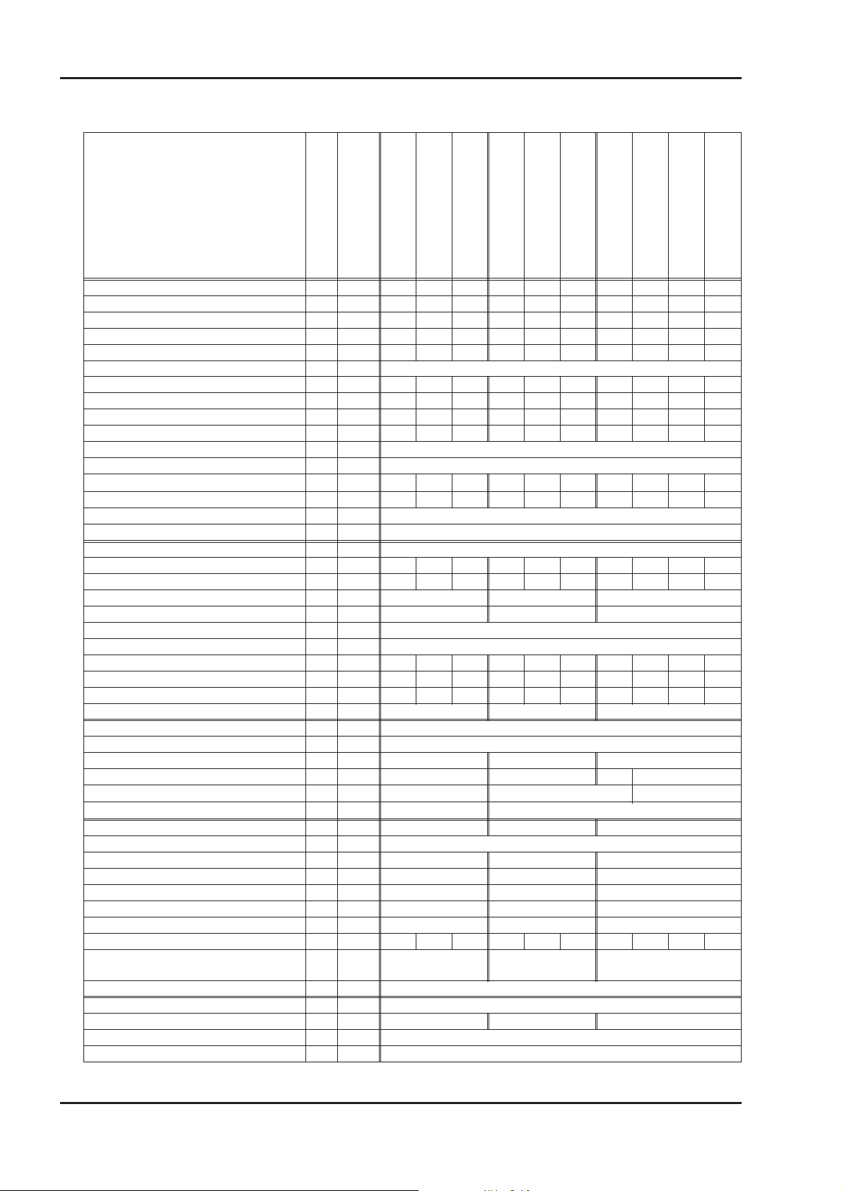
I.9.3 Technical data 6SM56..100-BV
Data Sym Dim
Standstill torque M
Standstill current I
Rated speed n
Torque constant K
Voltage constant K
Mains supply voltage U
Rated torque at n
n
Rated current I
Rated power P
Peak current I
Motor pole no. p
Resolver pole no. p
Winding resistance Phase-Phase
Nm 4,8 9,2 13,2 14,0 23,0 31,0 36,0 53,0 69,0 84,0
0BV
0BV
min-13000 3000 3000 3000 3000 3000 3000 3000 3000 3000
n
Nm/A 1,33 1,45 1,32 1,31 1,35 1,41 1,33 1,35 1,32 1,35
Trms
mVmin 114 124 113 112 115 121 114 116 113 115
E
n
M
Nm 4,8 9,0 12,5 13,7 21,9 28,6 35,1 50,1 63,1 75,0
nBV
n
kW 1,5 2,8 3,9 4,3 6,9 9,0 11,0 15,7 19,8 23,6
n
0max
Mot
Res
R
20 W 9,4 4,0 1,8 1,65 0,8 0,57 0,46 0,22 0,16 0,12
A 3,6 6,3 10,0 10,7 17,1 22,0 27,1 39,3 52,2 62,2
V 400
A 3,8 6,5 9,8 10,8 16,8 21,0 27,1 38,1 49,1 57,2
A 12,4 19,6 28,3 32,0 44,0 51,0 72,0 113,0 150,0 180,0
-6
-2
6SM 56S-3000-BV
6SM 56M-3000-BV
6SM 56L-3000-BV
6SM 71K-3000-BV
6SM 71S-3000-BV
6SM 71M-3000-BV
6SM 100K-3000-BV
6SM 100S-3000-BV
6SM 100M-3000-BV
6SM 100L-3000-BV
Winding inductance Phase-Phase L mH 54,0 30,0 15,8 19,6 12,0 9,0 10,5 7,0 5,0 4,0
Insulation class - - F, DIN 57530
Switch point thermal contact - °C 145 ± 5
Design - - IM B5 (V1, V3), DIN 42950
Rotor moment of inertia J kgcm² 5,2 10,0 15,0 20,0 31,0 42,0 74,0 108,0 141,0 175,0
Static friction torque M
Radial load permitted at shaft end with n
Axial load permitted at shaft end with n
n
n
Nm 0,154 0,18 0,208 0,23 0,28 0,334 0,4 0,49 0,58 0,67
R
F
N 530 700 1050
R
F
N 170 230 350
A
Tolerance class flange - - N, DIN42955
Vibration class - - N, DIN ISO 2373
Thermal time constant t
min 15 15 15 15 20 20 20 20 25 25
TH
Weight incl. ventilator G kg 7,8 9,7 12,0 14,2 18,2 22,5 29,5 36,5 43,5 52,5
Order number motor - - 81682 81683 81753 81679 81754 81680 84855 84856 84876 84874
Order number -BV- - - 65079 65078 65080
EMV-RES connector - - 12 poles, round
RES cable, shielded - mm² 4x2x0,25
Power connection - stud M4 M6 M8
Motor cable, shielded - mm² 4x1,5 4x4 4x6 4x16
max. Æ of motor cable
-mm 15 20 28
max. Æ of braking cable - mm 8 12,5
Holding torque M
Operating voltage U
electrical power P
Moment of inertia J
Release delay time t
Application delay time t
Weight of the brake G
Nm 12 20 60
BR
V= 24 +6/-10%
BR
W18 22 50
BR
kgcm² 3,6 9,5 57,5
BR
ms 30-60 20-60 70-160
BRH
ms 10-20 10-35 30-60
BRL
kg 1,1 1,9 5,4
BR
Order number with -G- - - 81868 81867 81866 81865 81864 81863 84699 84857 84877 84875
Motor cable with brake, shielded - mm²
4x1 + 2x0,75 or
4x1,5 + 2x0,75
4x2,5 + 2x1 -
Separate braking cable - mm² 4x1,5 or 4x2,5
Operating voltage ventilator U
Rated current ventilator I
V 230 (50-60 Hz)
BV
A 0,12 0,25 0,25
BV
Connector - - 4 poles
Protection class with ventilator -- IP54
16 Motor series 6SM45..100
Page 17
Kollmorgen 05.2000 Installation / Commissioning
II Installation / Commissioning
II.1 Important notes
Check that the servo-amplifier and motor match each other. Compare the rated
l
voltage and rated current of the unit. Carry out the wiring according to the wiring
diagram in the Installation and Commissioning Instructions for the servo-amplifier.
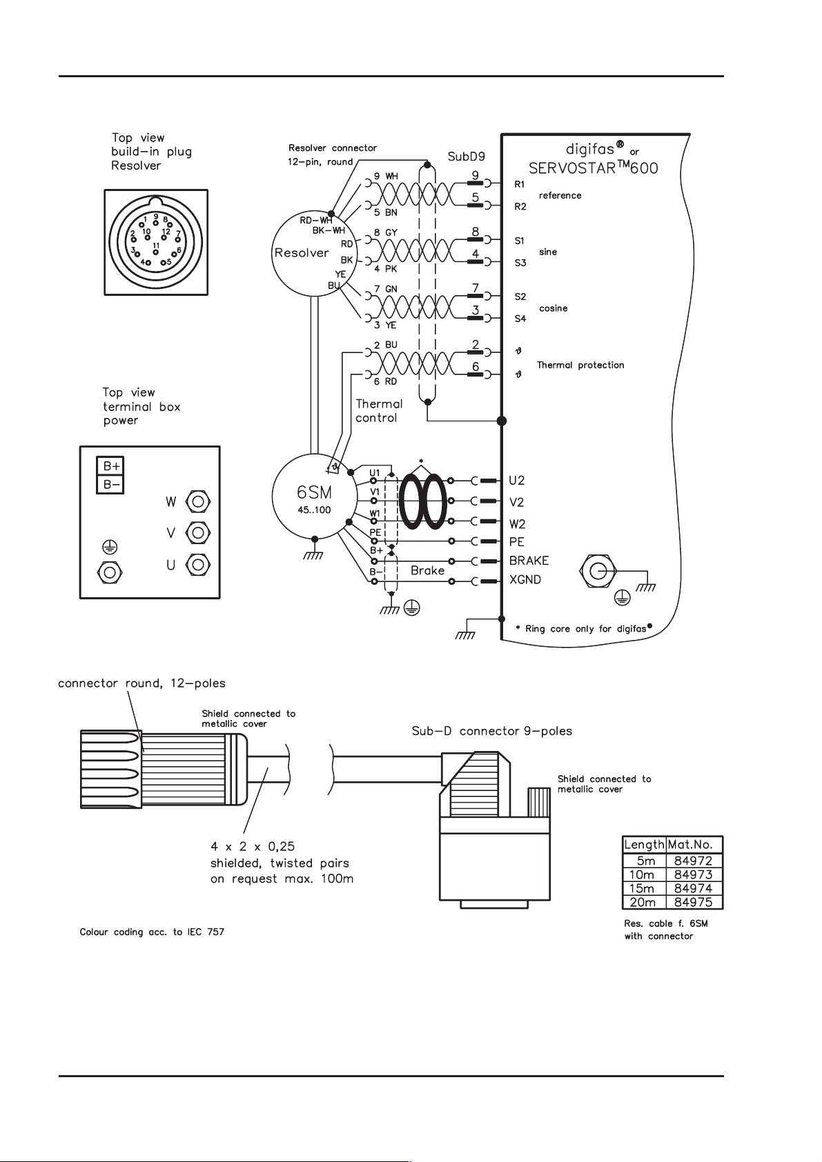
The connections to the motor are shown on pages 24 and 33.
Notes on the connection methods can be found on page 20.
Ensure that there is proper earthing of the servo-amplifier and the motor.
l
Route the power and control cables as separately as possible from one another
l
(separation > 20 cm). This will improve the immunity of the system to electromag
netic interference.
If a motor power cable is used which includes integral brake control leads, then
these brake control leads must be shielded. The shielding must be connected at
both ends (see under Installation Instructions for the servo-amplifier).
Install all cables carrying a heavy current with an adequate cross-section, as per
l
EN 60204. The recommended cross-section can be found in the Technical data.
Caution!
If a servo-amplifier of the series digifas® or SERVOSTAR™ is used and the
motor cable exceeds 25m, a boxed choke (type 3YL-xx, manufactured by
Seidel) and motor leads with the following diameters must be used:
-
Servo-amplifier choke box Max. cable diameter
digifas® 7201...7206 3YL-06 4x1mm²
SERVOSTAR™ 601...606 3YL-20 4x1mm²
SERVOSTAR™ 610 3YL-20 4x1,5mm²
SERVOSTAR™ 620 3YL-20 4x2,5 mm²
Connect up all shielding via a wide surface-area contact (low impedance) and
l
metallized connector housings or EMC-PG glands.
Check the compliance to the permitted radial and axial forces F
l
and FA.
R
When you use a toothed belt drive, the minimal permitted diameter of the pinion
M
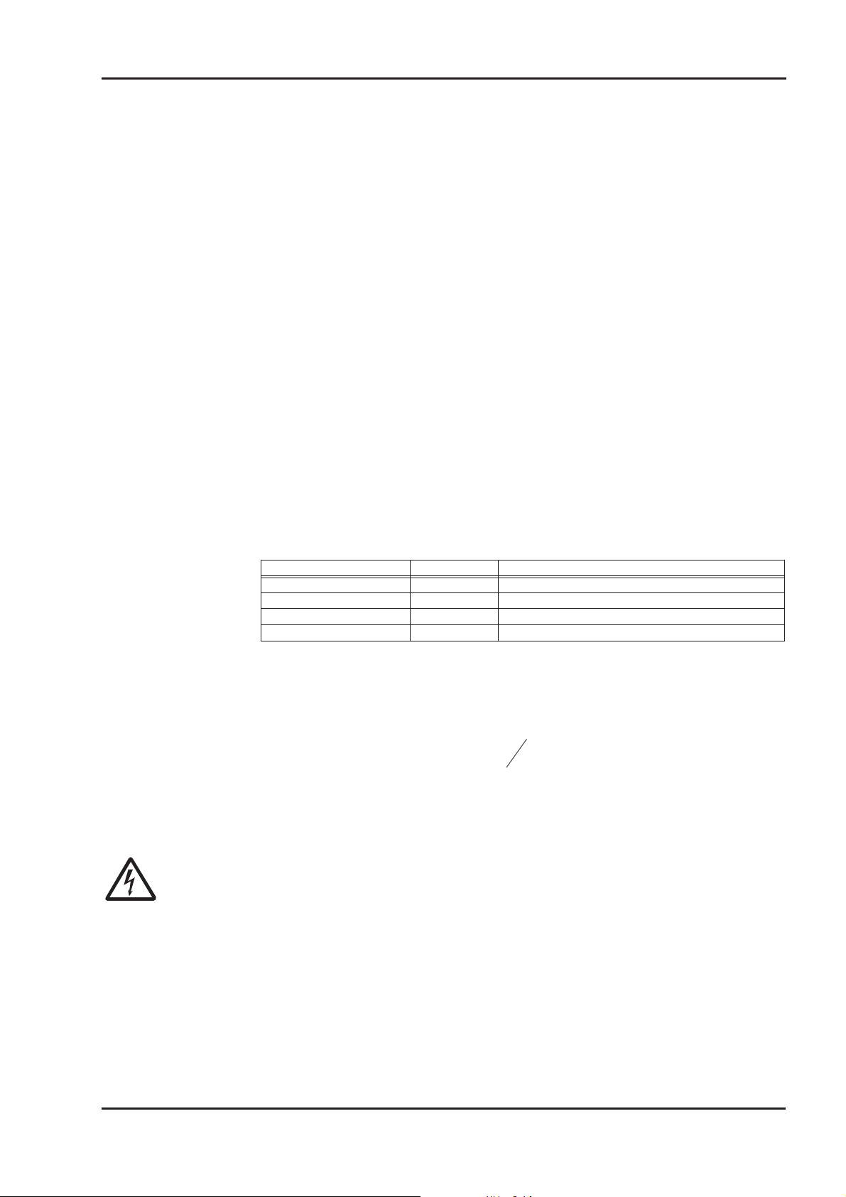
e.g. follows from the equation:
Ensure that there is adequate heat transfer in the surroundings and the motor
l
d
min
0
³´
F
.
2
R
flange, so that the maximum permissible flange temperature is not exceeded in S1
operation.
Caution!
Never undo the electrical connections to the motor while it is energised. A
dangerous voltage, resulting from residual charge, can be still present on the
capacitors up to 300 seconds after switch-off of the mains supply.
Measure the DC-link voltage and wait until it has fallen below 40V.
Even when the motor is not rotating, control and power leads may be live.
Motor series 6SM45..100 17
Page 18
Installation / Commissioning 05.2000 Kollmorgen
II.2 Assembly / Wiring
Only qualified staff with knowledge of mechanical engineering are permitted to
assemble the motor.
Only staff qualified and trained in electrical engineering are allowed to wire up the
motor.
The procedure is described as an example. A different method may be appropriate or
necessary, depending on the application of the equipment.
Warning!
Protect the motor from unacceptable stresses.
Take care, especially during transport and handling, that components are not bent
and that insulation clearances are not altered.
Always make sure that the motors are de-energized during assembly and wiring,
i.e. No voltage may be switched on for any piece of equipment which is to be
connected.
Ensure that the switch cabinet remains turned off (barrier, warning signs etc.).
The individual voltages will only be turned on again during commissioning
Note!
The ground symbol
you must provide an electrical connection, with as large a surface area as possible,
between the unit indicated and the mounting plate in the switch cabinet. This con
nection is to suppress HF interference and must not be confused with the PE
(protective earth) symbol
To wire up the motor, use the wiring diagrams in the Installation and Commis
sioning Instructions of the servo-amplifier which is used.
X, which you will find in the wiring diagrams, indicates that
-
W (protective measure to EN 60204).
-
18 Motor series 6SM45..100
Page 19
Kollmorgen 05.2000 Installation / Commissioning
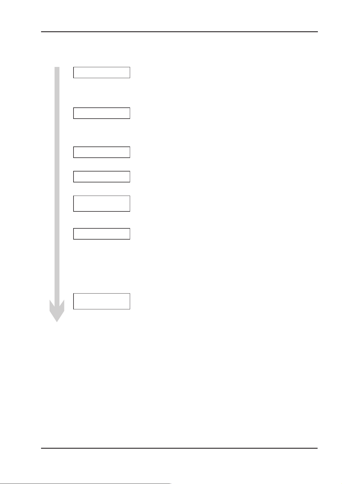
The following notes should help you to carry out the assembly and wiring in an appropriate se
quence, without overlooking anything.
Site
Ventilation
Assembly
Cable selection
Earthing
Shielding
The site must be free of conductive and aggressive material.
For V3-mounting (shaft end upwards), make sure that no liquids can
enter the bearings. If an encapsulated assembly is required, please
consult our applications department beforehand.
Ensure an unhindered ventilation of the motors and observe the
permissible ambient and flange temperatures.
For ambient temperatures above 40°C please consult our applications
department beforehand.
During assembly, take care that the motor is not overstressed when it
is fixed in place.
Select cables according to EN 60204
See the table in chapter II.1 when cable length exceeds 25m.
Use correct earthing and EMC-shielding according to the Installation
Instructions for the servo-amplifier which is used. Earth the mounting
plate and motor casing. For connection methods see chapter II.2.1
-
Wiring
Check
— Route power cables as separately as possible from control cables
— Connect up the resolver
— Connect the motor leads, install ring cores or motor chokes close to
— the servo-amplifier, connect shields to shielding terminals or EMC
— connectors at both ends
— Connect the holding brake, if used, Connect shielding at both ends.
— Connect the separate fan, if used.
Final check of the installed wiring, according to the wiring diagram
which was used
Motor series 6SM45..100 19
Page 20
Installation / Commissioning 05.2000 Kollmorgen
II.2.1 Connection methods
Carry out the wiring in accordance with the valid standards and regulations.
l
Only use our preassembled shielded cables for the resolver connections.
l
Connect up the shielding according to the wiring diagrams in the Installation
l
Instructions for the servo-amplifier.
l
Incorrectly installed shielding inevitably leads to EMC interference.
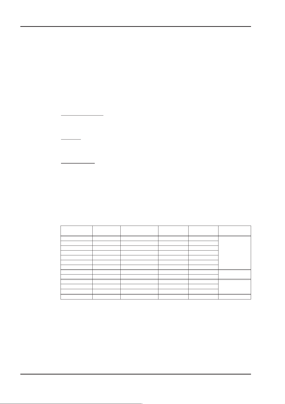
In the table below you find all cables supplied by us. They are cUL approved. Further
information referring to chemical, mechanical and electrical qualities can be received from
our applications department.
Insulating material
Sheathing - PUR (Polyurethane, identification 11Y)
core insulation - PETP (Polyesteraphtalate, identification 12Y)
Capacity
Motor cable - less than 150 pF/m
Resolver cable - less than 120 pF/m
Technical Data
— All cables are suitable for trailing.
— Technical data refer to mobile usage of cables.
Life time : 1 Million bending cycles
— The temperature range refers to the operation temperature.
— Identification: N = numbered cores
F = cores with colour code according to DIN 47100
B = cores with letter identification
( ) = shielding
Cores
[mm²]
(4x1,0) F -30 / +80 10,5 105
(4x1,5) B -30 / +80 11,3 115
(4x2,5) N -5 / +70 12,7 125
(4x4) N -5 / +70 12,8 130
(4x6) N -5 / +70 16,1 160
(4x10) N -5 / +70 19,0 190
(4x16) N -5 / +70 23,3 235
(4x1,5) F -30 / +80 11,3 115
(4x2,5) B -5 / +70 12,7 125
(4x1,0+(2x0,75)) F -30 / +80 12 120 Motor cable with
(4x1,5+(2x0,75)) B -10 / +80 12,5 125
(4x2,5+(2x1)) B -30 / +80 13,8 140
(4x2x0,25) F -30 / +80 6,9 60 Resolver cable
Identification Temperature range
[°C]
Cable diameter
[mm]
Bending radius
[mm]
Remarks
Motor cable
Braking cable
integral brake
control leads
20 Motor series 6SM45..100
Page 21
Kollmorgen 05.2000 Installation / Commissioning
II.3 Commissioning
The procedure for commissioning is described as an example. A different method may be
appropriate or necessary, depending on the application of the equipment.
Only specialist personnel with extensive knowledge in the areas of electrical engineering /
drive technology are allowed to commission the drive unit of servo-amplifier and motor.
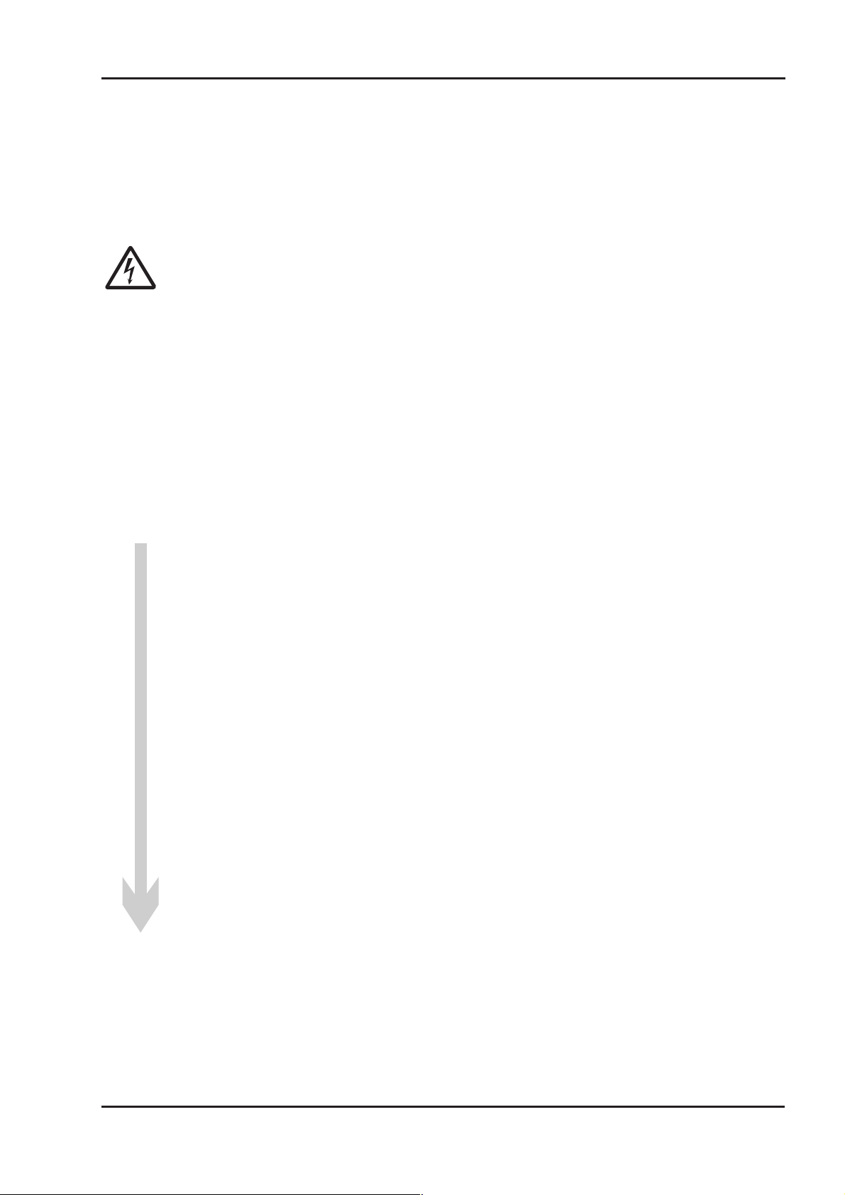
Caution!
Check that all live connection points (terminal boxes) are safe against accidental
contact. Deadly voltages can occur, up to 900V.
Never undo the electrical connections to the motor when it is live. The residual
charge in the capacitors of the servo-amplifier can produce dangerous voltages up
to 300 seconds after the mains supply has been switched off.
The surface temperature of the motor can reach 100°C in operation.
Check (measure) the temperature of the motor. Wait until the motor has cooled
down below 40°C before touching it.
Make sure that, even if the drive starts to move unintentionally, no danger can
result for personnel or machinery.
Check the assembly and orientation of the motor.
l
Check the drive components (clutch, gear unit, belt pulley) for the correct seating
l
and setting (observe the permissible radial and axial forces).
Check the wiring and connections to the motor and the servo-amplifier.
l
Check that the earthing is correct.
Test the function of the holding brake, if used.
l
(apply 24V, the brake must be released).
Check whether the rotor of the motor revolves freely
l
(release the brake, if necessary). Listen out for grinding noises.
Check that all the required measures against accidental contact with live and
l
moving parts have been carried out.
Carry out any further tests which are specifically required for your system.
l
Now commission the drive according to the commissioning instructions for the
l
servo amplifier.
In multi-axis systems, individually commission each drive unit
l
(servo-amplifier and motor).
Motor series 6SM45..100 21
Page 22

Installation / Commissioning 05.2000 Kollmorgen
This page has been deliberately left blank.
22 Motor series 6SM45..100
Page 23
Kollmorgen 05.2000 - A.4.017.3/04, 4/20 Drawings
III Drawings
III.1 Non-ventilated motors
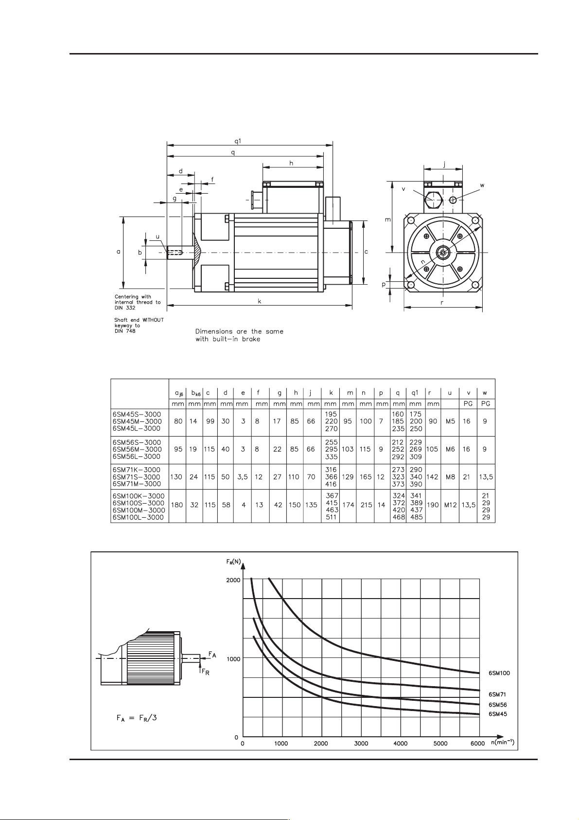
III.1.1 Dimensions 6SM45..100
III.1.2 Radial-/axial force at the shaft end
Motor series 6SM45..100 23
Page 24
Drawings 05.2000 - A.4.017.4/10 Kollmorgen
III.1.3 Wiring diagram 6SM45..100
24 Motor series 6SM45..100
Page 25
Kollmorgen 05.2000 - A.4.036.3/13, 21 Drawings
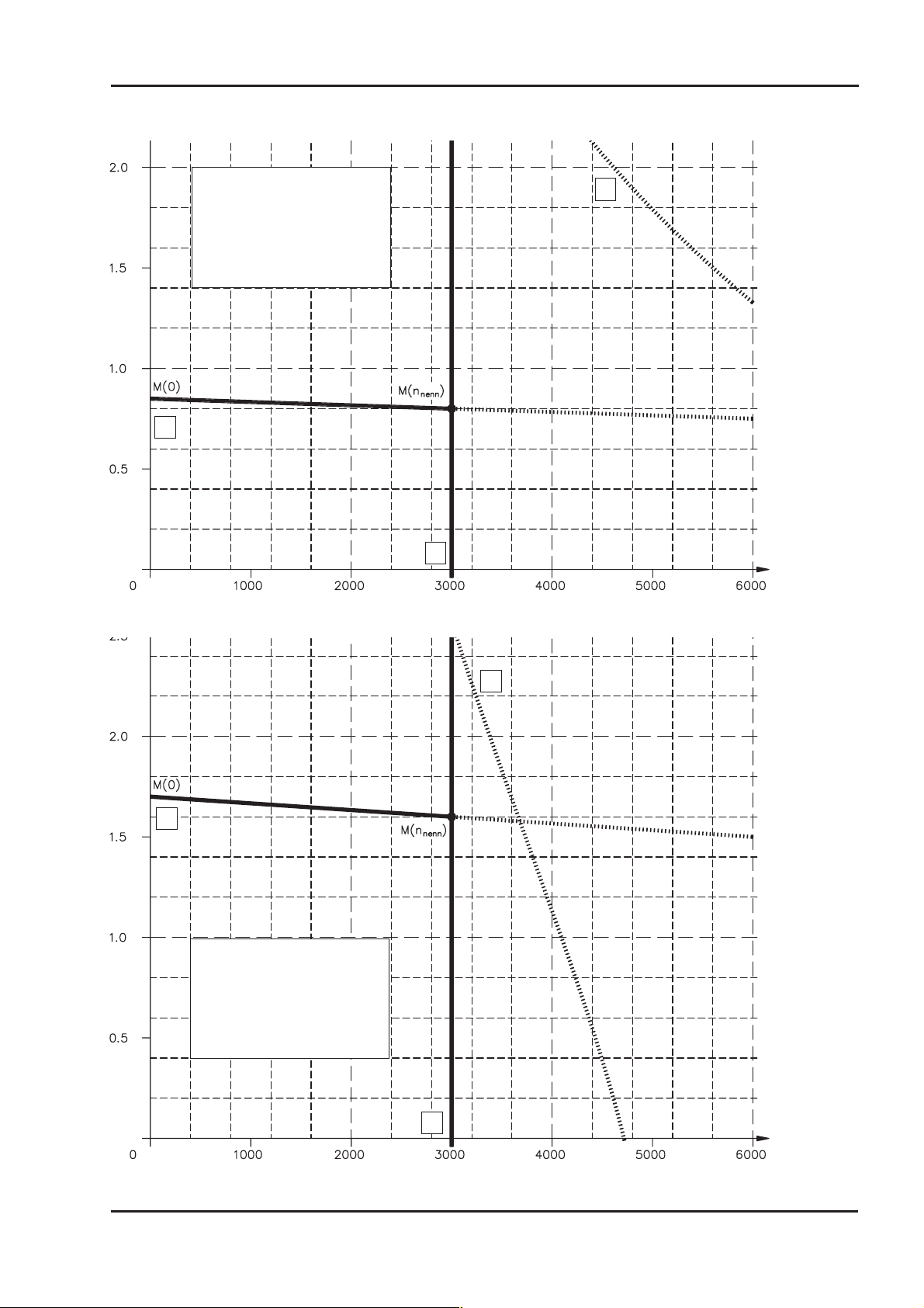
III.1.4 Torque characteristics 6SM45S-3000
Legend:
-1
X-axis : speed [min
]
Y-Axis : torque [Nm]
1 : Performance curve
2 : cut-off characteristic M(n)
3 : rated speed n
1
n
3
III.1.5 Torque characteristics 6SM45M-3000
2
1
Legend:
X-Axis : Speed [min
Y-Axis : Torque [Nm]
1 : Performance curve
2 : Cut-off characteristic M(n)
3 : Rated speed n
2
-1
]
n
3
Motor series 6SM45..100 25
Page 26
Drawings 05.2000 - A.4.036.3/14, 22 Kollmorgen
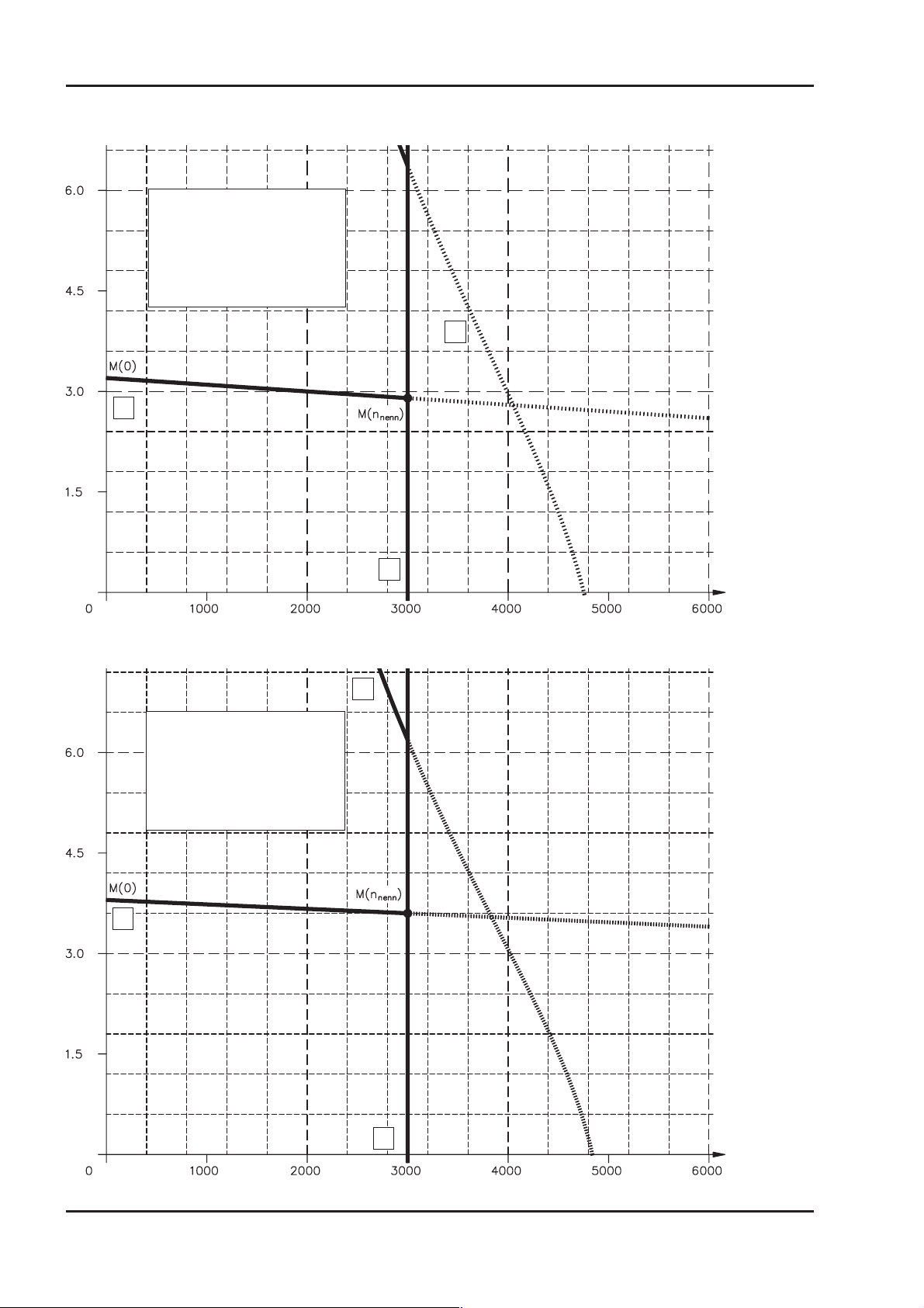
III.1.6 Torque characteristics 6SM45L-3000
Legend:
-1
X-Axis : Speed [min
Y-Axis : Torque [Nm]
1 : Performance curve
2 : Cut-off characteristic M(n)
3 : Rated speed n
1
]
n
2
3
III.1.7 Torque characteristics 6SM56S-3000
2
Legend:
-1
X-Axis : Speed [min
Y-Axis : Torque [Nm]
1 : Performance curve
2 : Cut-off characteristic M(n)
3 : Rated speed n
1
]
n
3
26 Motor series 6SM45..100
Page 27
Kollmorgen 05.2000 - A.4.036.3/51, 52 Drawings
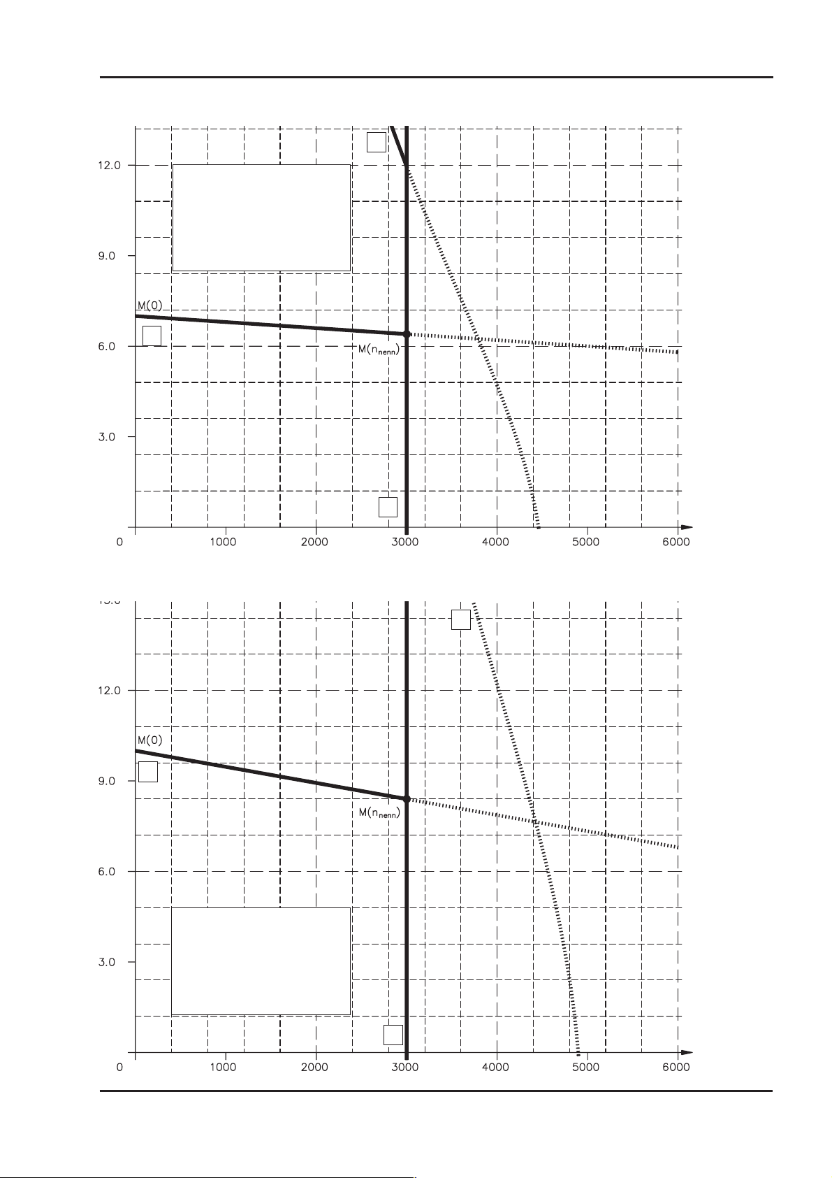
III.1.8 Torque characteristics 6SM56M-3000
2
Legend:
-1
X-Axis : Speed [min
Y-Axis : Torque [Nm]
1 : Performance curve
2 : Cut-off characteristic M(n)
3 : Rated speed n
1
]
n
3
III.1.9 Torque characteristics 6SM56L-3000
2
1
Legend:
-1
X-Axis : Speed [min
]
Y-Axis : Torque [Nm]
1 : Performance curve
2 : Cut-off characteristic M(n)
3 : Rated speed n
n
3
Motor series 6SM45..100 27
Page 28
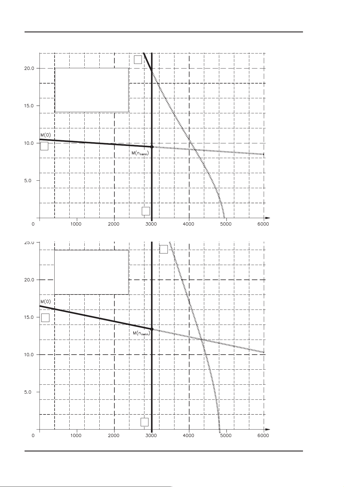
Drawings 05.2000 - A.4.036.3/15, 53 Kollmorgen
III.1.10 Torque characteristics 6SM71K-3000
2
Legend:
-1
X-Axis : Speed [min
Y-Axis : Torque [Nm]
1 : Performance curve
2 : Cut-off characteristic M(n)
3 : Rated speed n
1
]
n
3
III.1.11 Torque characteristics 6SM71S-3000
2
Legend:
-1
X-Axis : Speed [min
Y-Axis : Torque [Nm]
1 : Performance curve
2 : Cut-off characteristic M(n)
3 : Rated speed n
1
]
n
3
28 Motor series 6SM45..100
Page 29
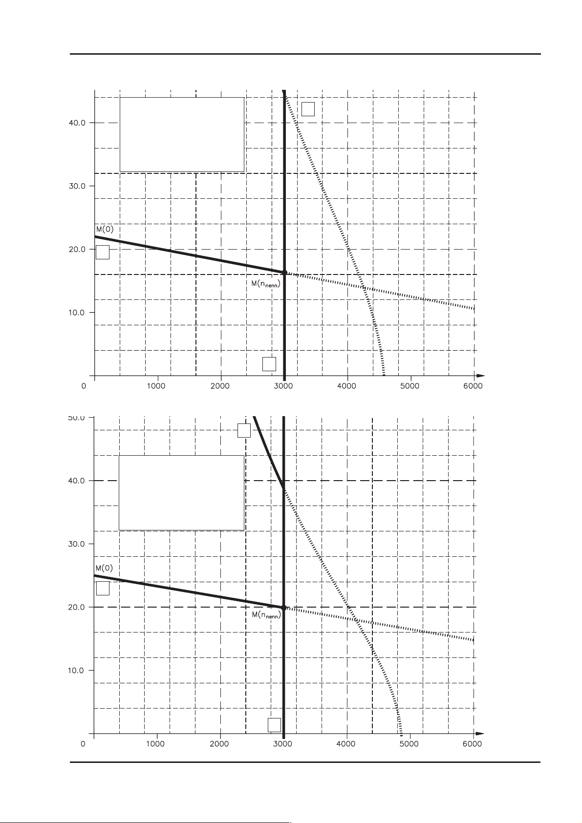
Kollmorgen 05.2000 - A.4.036.3/16, 50 Drawings
III.1.12 Torque characteristics 6SM71M-3000
Legend:
X-Axis : Speed [min
Y-Axis : Torque [Nm]
1 : Performance curve
2 : Cut-off characteristic M(n)
3 : Rated speed n
1
-1
]
n
3
2
III.1.13 Torque characteristics 6SM100K-3000
2
Legend:
-1
X-Axis : Speed [min
Y-Axis : Torque [Nm]
1 : Performance curve
2 : Cut-off characteristic M(n)
3 : Rated speed n
1
]
n
3
Motor series 6SM45..100 29
Page 30
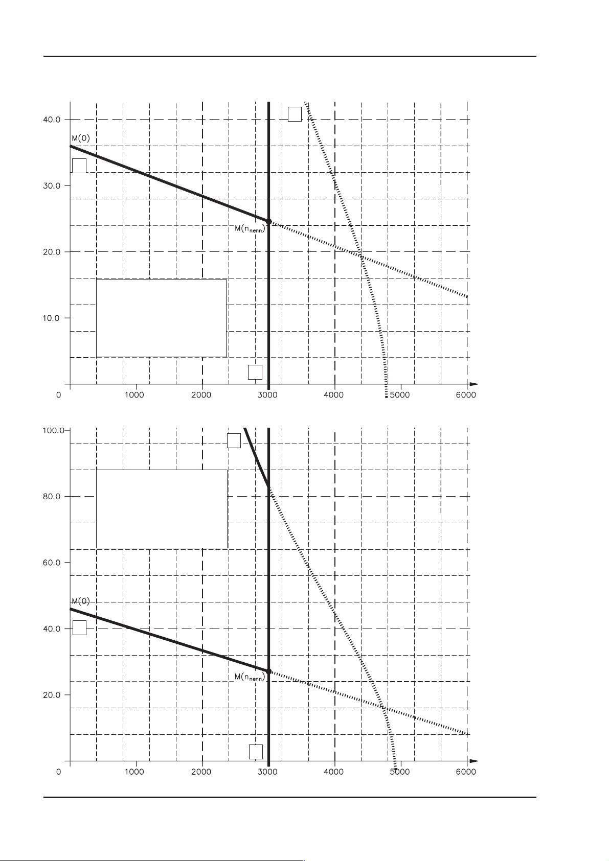
Drawings 05.2000 - A.4.036.3/18, 19 Kollmorgen
III.1.14 Torque characteristics 6SM100S-3000
2
1
Legend:
-1
X-Axis : Speed [min
Y-Axis : Torque [Nm]
1 : Performance curve
2 : Cut-off characteristic M(n)
3 : Rated speed n
]
n
3
III.1.15 Torque characteristics 6SM100M-3000
2
Legend:
-1
X-Axis : Speed [min
Y-Axis : Torque [Nm]
1 : Performance curve
2 : Cut-off characteristic M(n)
3 : Rated speed n
1
]
n
3
30 Motor series 6SM45..100
Page 31
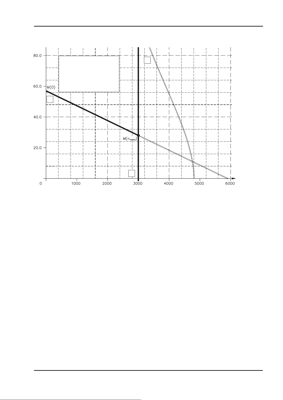
Kollmorgen 05.2000 - A.4.036.3/17 Drawings
III.1.16 Torque characteristics 6SM100L-3000
Legend:
X-Axis : Speed [min
Y-Axis : Torque [Nm]
1 : Performance curve
2 : Cut-off characteristic M(n)
3 : Rated speed n
1
2
-1
]
n
3
Motor series 6SM45..100 31
Page 32

Drawings 05.2000. .A.4.017.3/09, 4/21 Kollmorgen
III.2 Ventilated motors
III.2.1 Dimensions 6SM56..100-BV
III.2.2 Radial-/axial force at the shaft end
32 Motor series 6SM45..100
Page 33
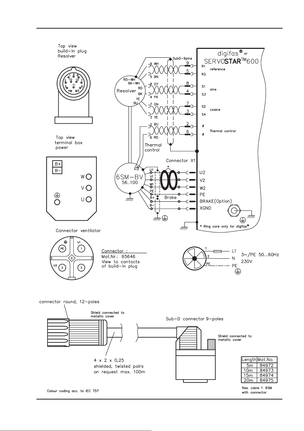
Kollmorgen 05.2000 - A.4.017.4/11 Drawings
III.2.3 Wiring diagram 6SM56..100-BV
Motor series 6SM45..100 33
Page 34
Drawings 05.2000 .- A.4.029.4/07 Kollmorgen
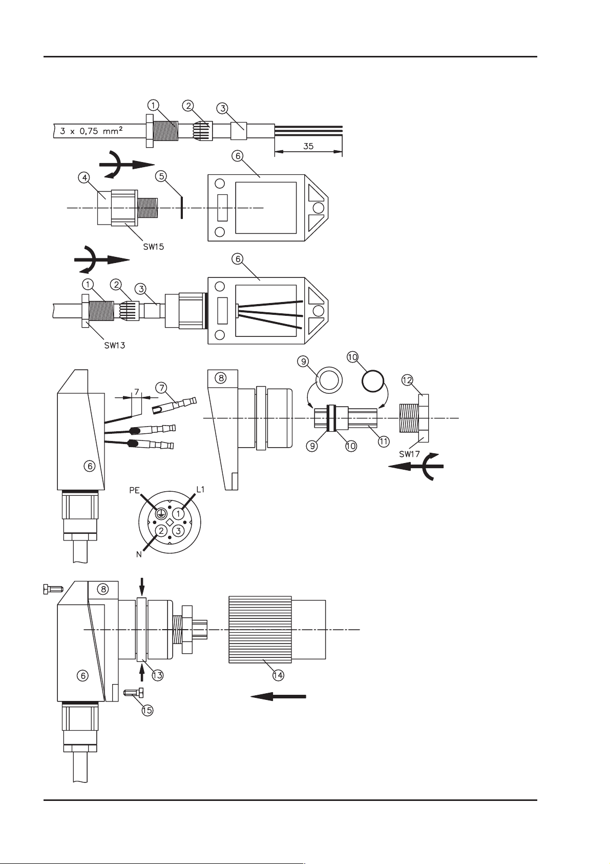
III.2.4 Fan connection
Strip off the outer insulation of the cable
over a length of 35mm. Push the parts
1, 2‚ and 3 of the PG7 connection onto
the cable.
Push the O-Ring 5 onto the thread of
part 4 of the PG7 connection and screw
part 4 into the plug housing 6, using an
open-ended spanner (15 a/f).
Push the rubber ring 3 into the strain
relief 2. Push the cable so far through
the hole into the plug housing 6 that
about 1mm is visible. Screw up the PG
with an open-ended spanner (13 a/f).
Strip off the ends of the cores over a length of 7mm and solder them to
the contact inserts 7. Push the rubber seal 9 and the O-ring 10 onto
the insert 11. Push the insert 11 into the plug housing 8. Screw part
12 right up to the stop with an open-ended spanner (17 a/f). Push the
contact inserts from the left into the insert, observing the correct core
colour (use appropriate pliers), until they snap into position
Fit parts 6 und 8 together and screw
them together with the three screws 15.
Compress the spring ring 13 lightly and
push on the knurled sleeve 14, until it
snaps into position.
34 Motor series 6SM45..100
Page 35
Kollmorgen 05.2000 - A.4.036.3/51, 54 Drawings
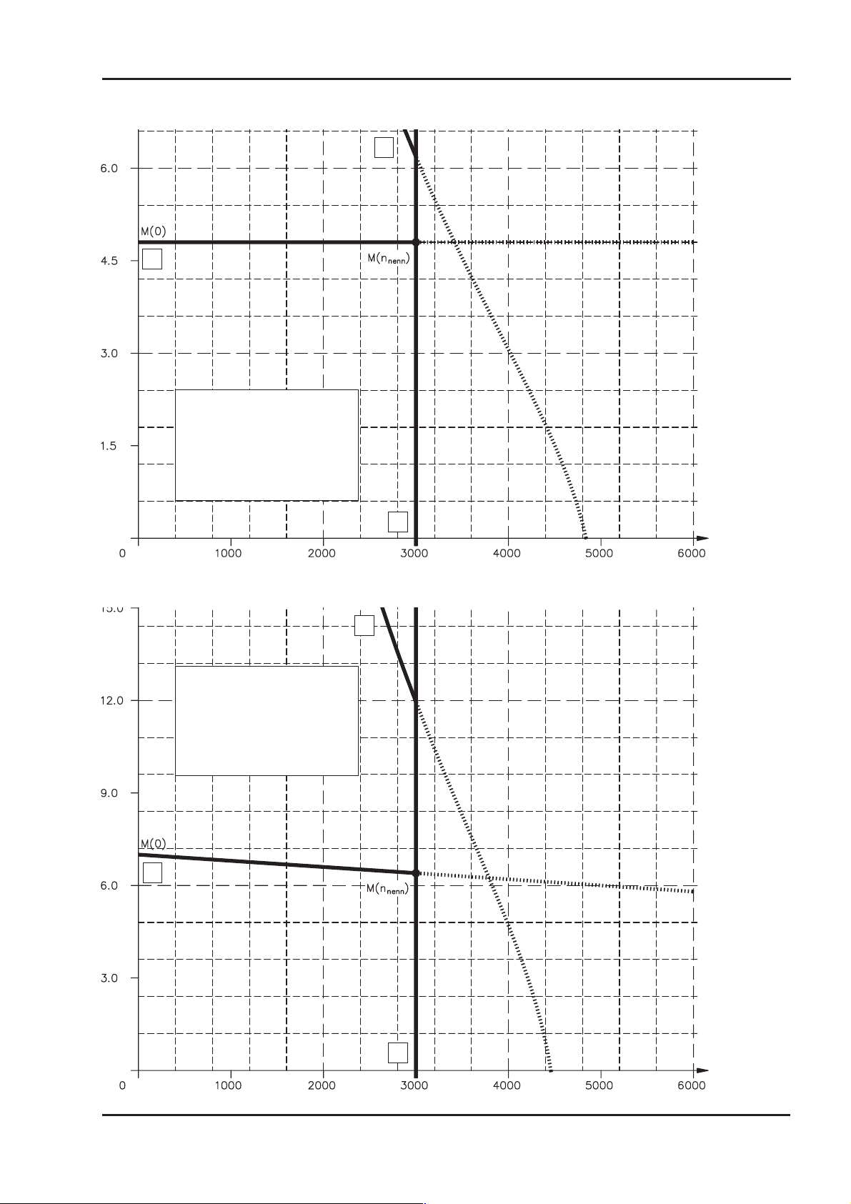
III.2.5 Torque characteristics 6SM56S-3000-BV
2
1
Legend:
-1
X-Axis : Speed [min
Y-Axis : Torque [Nm]
1 : Performance curve
2 : Cut-off characteristic M(n)
3 : Rated speed n
]
n
3
III.2.6 Torque characteristics 6SM56M-3000-BV
2
Legend:
-1
X-Axis : Speed [min
Y-Axis : Torque [Nm]
1 : Performance curve
2 : Cut-off characteristic M(n)
3 : Rated speed n
1
]
n
3
Motor series 6SM45..100 35
Page 36
Drawings 05.2000 - A.4.036.3/56, 57 Kollmorgen
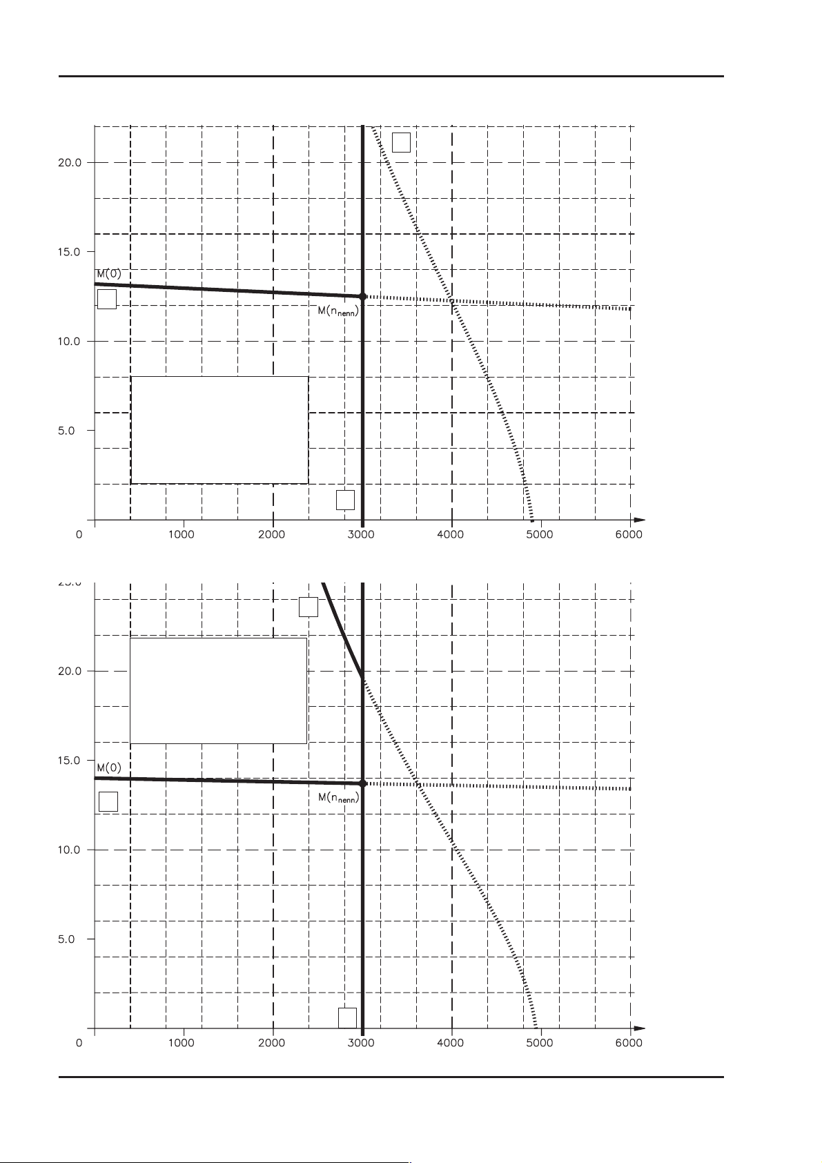
III.2.7 Torque characteristics 6SM56L-3000-BV
2
1
Legend:
-1
X-Axis : Speed [min
Y-Axis : Torque [Nm]
1 : Performance curve
2 : Cut-off characteristic M(n)
3 : Rated speed n
]
n
3
III.2.8 Torque characteristics 6SM71K-3000-BV
2
Legend:
-1
X-Axis : Speed [min
Y-Axis : Torque [Nm]
1 : Performance curve
2 : Cut-off characteristic M(n)
3 : Rated speed n
1
]
n
3
36 Motor series 6SM45..100
Page 37
Kollmorgen 05.2000 - A.4.036.3/58, 59 Drawings
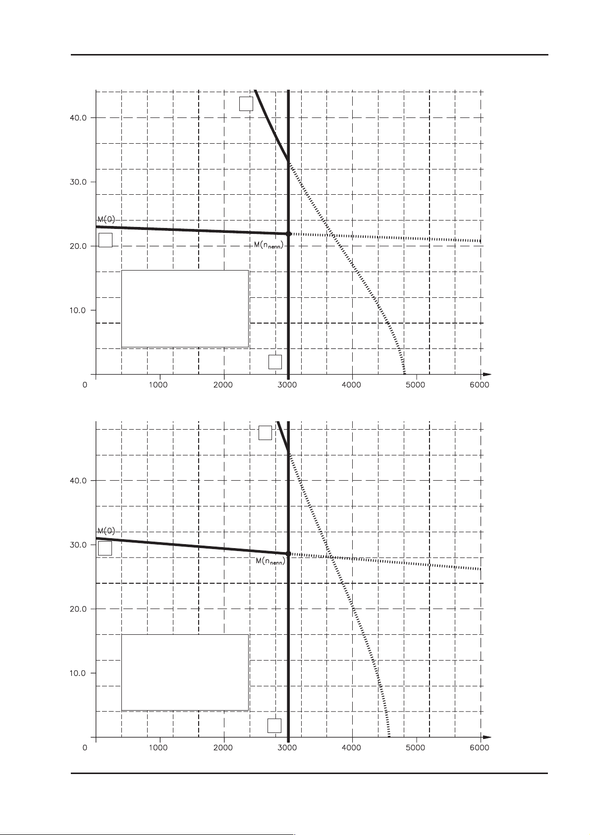
III.2.9 Torque characteristics 6SM71S-3000-BV
2
1
Legend:
-1
X-Axis : Speed [min
Y-Axis : Torque [Nm]
1 : Performance curve
2 : Cut-off characteristic M(n)
3 : Rated speed n
]
n
3
III.2.10 Torque characteristics 6SM71M-3000-BV
2
1
Legend:
-1
X-Axis : Speed [min
Y-Axis : Torque [Nm]
1 : Performance curve
2 : Cut-off characteristic M(n)
3 : Rated speed n
]
n
3
Motor series 6SM45..100 37
Page 38
Drawings 05.2000 - A.4.036.3/60, 61 Kollmorgen
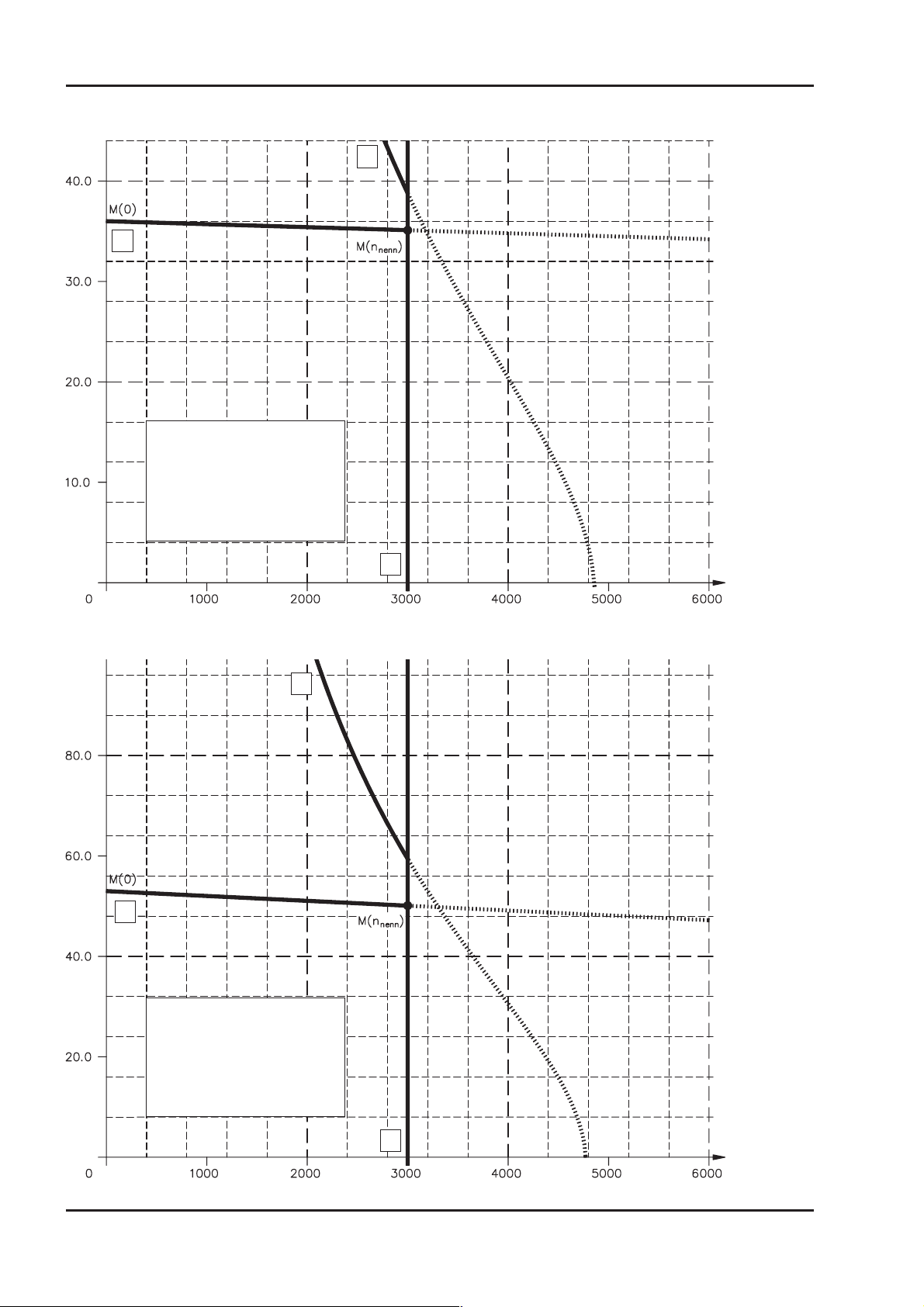
III.2.11 Torque characteristics 6SM100K-3000-BV
2
1
Legend:
-1
X-Axis : Speed [min
Y-Axis : Torque [Nm]
1 : Performance curve
2 : Cut-off characteristic M(n)
3 : Rated speed n
]
n
3
III.2.12 Torque characteristics 6SM100S-3000-BV
2
1
Legend:
-1
X-Axis : Speed [min
Y-Axis : Torque [Nm]
1 : Performance curve
2 : Cut-off characteristic M(n)
3 : Rated speed n
]
n
3
38 Motor series 6SM45..100
Page 39
Kollmorgen 05.2000 - A.4.036.3/62, 63 Drawings
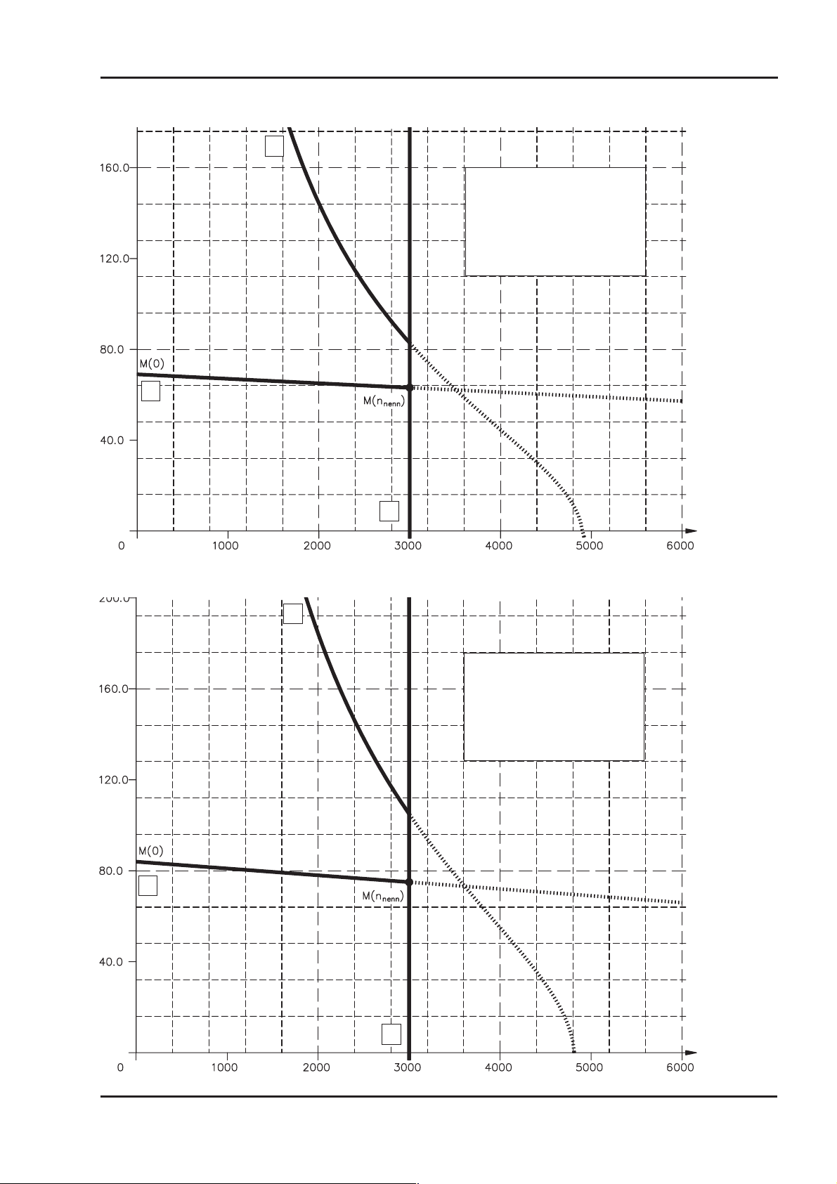
III.2.13 Torque characteristics 6SM100M-3000-BV
2
Legend:
-1
X-Axis : Speed [min
Y-Axis : Torque [Nm]
1 : Performance curve
2 : Cut-off characteristic M(n)
3 : Rated speed n
1
]
n
3
III.2.14 Torque characteristics 6SM100L-3000-BV
2
Legend:
X-Axis : Speed [min
Y-Axis : Torque [Nm]
1 : Performance curve
2 : Cut-off characteristic M(n)
3 : Rated speed n
1
-1
]
n
3
Motor series 6SM45..100 39
Page 40

Drawings 05.2000 Kollmorgen
This page has been deliberately left blank
40 Motor series 6SM45..100
Page 41
Kollmorgen 05.2000 Appendix
IV Appendix
IV.1 Delivery package, transport, storage, maintenance, disposal
Delivery package:— Motor from the 6SM45..100 series
— Technical description (documentation), 1 copy per delivery
— Motor package leaflet (short info)
Transport: — Climate category 2K3 to EN 50178
— Transport temperature—25...+70°C, max. 20K/hr change
— Transport humidity rel. humidity 5% - 95% , no condensation
— only by qualified personnel
— only in the manufacturer’s original recyclable packaging
— avoid shocks
— if the packaging is damaged, check the motor for visible damage.
— Inform the carrier and, if appropriate, the manufacturer.
Packaging:
Motor type Carton Pallet or skeleton box Max. stacking height
6SM45 X 6
6SM56 X 6
6SM71K/71S X 5
6SM71M X 1
6SM100 X 1
Storage: — Climate category 1K4 to EN 50178
— Storage temperature —25...+55°C, max. variation 20K/hr. — Humidity rel. humidity 5% - 95%, no condensation
— only in the manufacturer’s original recyclable packaging
— max. stacking height see table under Packaging
— Storage time unlimited
Maintenance: — Only by qualified personnel
— The ball bearings have a grease packing which is adequate for
— 20,000 hours of operation under normal conditions. The bearings
— should be replaced after 20,000 hours of operation under rated
— conditions.
— Check the motor for bearing noise every 2500 operating hours,
— respectively each year. If any noises are heard, then the operation
— of the motor must stop, the bearings must be replaced.
— Opening the motor invalidates the warranty.
Cleaning: — If the housing is dirty: clean with Isopropanol or similar.
do not immerse or spray
— If a separate fan is fitted: check the fan mesh for dirt twice a year.
— If necessary, clean the mesh with a brush.
Disposal: — The disposal should be carried out by a certified disposal company.
— Ask us for addresses.
Motor series 6SM45..100 41
Page 42
Appendix 05.2000 Kollmorgen
IV.2 Fault-finding
The following table is to be seen as a “First Aid” box. There can be a large number of dif
ferent reasons for a fault, depending on the particular conditions in your system. The fault
causes described below are mostly those which directly influence the motor. Peculiarities
which show up in the control loop behaviour can usually be traced back to an error in the
parameterization of the servo-amplifier. The documentation for the servo-amplifier and
the operator software provides information on these matters.
For multi-axis systems there may be further hidden reasons for faults.
Our applications department can give you further help with your problems.
Fault Possible cause
— Servo-amplifier not enabled
Motor doesn’t
rotate
Motor runs away
Motor oscillates
Error message:
brake
Error message:
output stage fault
Error message:
resolver
Error message:
motor temperature
Brake does not
grip
— Break in setpoint lead
— Motor phases in wrong sequence
— Brake not released
— Drive is mechanically blocked
— Motor phases in wrong sequence
— ROD cable faulty or not properly plugged in
(for option -IL- )
— Break in the shielding of the resolver cable
— amplifier gain to high
— Short-circuit in the supply voltage lead to
the motor holding brake
— Faulty motor holding brake
— Motor cable has short-circuit or earth short
— Motor has short-circuit or earth short
— Resolver connector is not properly plugged in
— Break in res. cable, cable crushed or similar
— Motor thermostat has switched
— Loose resolver connector or break in
resolver cable
— Required holding torque too high
— Brake faulty
— Motor shaft axially overloaded
Measures to remove the cause of
the fault
— Supply ENABLE signal
— Check setpoint lead
— Correct the phase sequence
— Check brake controls
— Check mechanism
— Correct the phase sequence
— Check ROD/SSI cable
— Replace resolver cable
— use motor default values
— Remove the short-circuit
— Replace motor
— Replace cable
— Replace motor
— Check connector
— Check cables
— Wait until the motor has cooled
down. Then investigate why the
motor becomes so hot.
— Check connector, replace resolver
cable if necessary
— Check the dimensioning
— Replace motor
— Check the axial load, reduce it.
Replace motor, since the bearings
have been damaged
-
42 Motor series 6SM45..100
Page 43

Kollmorgen 05.2000 Appendix
IV.3 Index
Text Page Text Page
A Ambient temperature ...........10
Assembly .................19
Axial force ................11
Axial force, diagram ...........23
B Break response times ..........14
C Commissioning..............21
Connection method ...........12
Contents ..................3
Coupling .................11
D Delivery package .............41
Dimensions................23
Disposal .................41
E Earthing .................19
F Fan connection ..............34
Feedback unit ..............12
Flange temperature ...........10
H Holding brake ..............12
I Insulation material class .........12
M Maintenance ...............41
Manufacturer declaration .........7
Motor lead ................20
N Nameplate ................13
O Options ..................13
P Peak current ...............14
Power derating ..............10
Protection class .............11
Protective device .............11
R Radial force ...............11
Radial force, diagram ..........23
Rated current ...............14
Rated torque ...............14
Resolver .................12
Resolver lead...............20
Rotor moment of inertia .........14
S Safety notes ................5
Separate fan ...............13
Servo amplifier ..............10
Shielding .................19
Site ....................19
Standstill current .............14
Standstill torque .............14
Storage ..................41
Storage humidity .............41
Storage temperature ...........41
Storage time ...............41
Style ...................11
T Technical data ..............15
Thermal time constant ..........14
Thermostat ................11
Torque constant .............14
Transport .................41
V Ventilation ................19
Vibration class ..............12
Voltage constant .............14
W Wiring ..................19
Wiring diagram ..............24
Motor series 6SM45..100 43
Page 44
Vertrieb und Service / Sales and Service / Agence et Services
Bundesrepublik Deutschland/
Germany/Allemagne
Kollmorgen Seidel GmbH & Co. KG
Verkaufsniederlassung Nord
Heinrich-Albertz- Str. 40
29221 Celle
Tel.: +49(0)5141 - 98 10 40
Fax: +49(0)5141 - 98 10 41
Kollmorgen Seidel GmbH & Co. KG
Verkaufsniederlassung West
Lilienstraße 3
42719 Solingen
Tel.: +49(0)212-2307799
Fax: +49(0)212-2307797
Kollmorgen Seidel GmbH & Co. KG
Verkaufsniederlassung Süd-West
Lessingstr. 41
75015 Bretten
Tel.: +49(0)7252 - 97 39 040
Fax: +49(0)7252 - 97 39 055
Kollmorgen Seidel GmbH & Co. KG
Verkaufsniederlassung Süd-Ost
Landsbergerstr. 17
86947 Weil
Tel.: +49(0)8195 - 99 92-50
Fax: +49(0)8195 - 99 92-33
Servo-Dyn
Technik GmbH
Münzgasse 10
01067 Dresden
Tel.: +49(0)351 - 49 05 793
Fax: +49(0)351 - 49 05 794
Dänemark/Denmark/Danemark
DIGIMATIC A/S
"Laerkenfeldt"
Aalkaergaardvej 20
8700 Horsens Nord
Tel.:+45-75656666
Fax: +45 - 75 65 68 33
Finnland/Finland/Finlande
Drivematic OY
Hevosenkenkä 4
28430 Pori
Tel.:+358-2-61003311
Fax: +358-2-61003350
Frankreich/France/France
Kollmorgen Seidel GmbH & Co. KG
Parc technologique St.Jacques
2 rue Pierre et Marie Curie
54320 Maxéville
Tel.: +33(0)3 83 95 44 80
Fax: +33(0)3 83 95 44 81
Kollmorgen Seidel GmbH & Co. KG
216 Lotissement Les Peiffendes
Le Sonnant d'Uriage
38410 Uriage
Tel.: +33(0)4 76 59 22 30
Fax: +33(0)4 76 59 22 31
Großbritannien/
Great Britain/Royaume-Uni
Kollmorgen
PO Box 147, KEIGHLEY
West Yorkshire, BD21 3XE
Tel.: +44(0)15 35 - 60 76 88
Fax: +44(0)15 35 - 68 05 20
Heason Technologies Group
Claremont Lodge
Fontwell Avenue
Eastergate Chichester PO20 6RY
Tel.: +44(0)12 43 - 54 54 00
Fax: +44(0)12 43 - 54 45 90
Italien/Italy/Italie
M.C.A. s.r.l.
Via f. Turati 21
20016 Pero (Mi)
Tel.: +39(0)02 - 33 91 04 50
Fax: +39(0)02 - 33 90 85 8
Niederlande/
Netherlands/Pays-Bas
Dynamic Drives
Jan van der Heydenstraat 24a
2665 JA Bleiswijk
Tel.: +31(0)10 - 52 15 490
Fax: +31(0)10 - 52 18 994
Schweden/Sweden/Suéde
SDT AB
25467 Helsingborg
Tel.: +46(0)42 - 380 800
Fax: +46(0)42 - 380 813
Stockholm
12030 Stockholm
Tel.: +46(0)8 - 640 77 30
Fax: +46(0)8 - 641 09 15
Göteborg
42671 Västra Frölunda
Tel.: +46(0)31 - 69 62 60
Fax: +46(0)31 - 69 62 69
Schweiz/Switzerland/Suisse
Kollmorgen Seidel GmbH & Co. KG
Buhnrain 30
8052 Zürich
Tel.: +41(0)1 - 300 29 65
Fax: +41(0)1 - 300 29 66
Spanien/Spain/Espagne
BROTOMATIC S.L.
C/San Miguel de Acha, 2 Pab.3
01010 Vitoria (ALAVA)
Tel.: +34 945 - 24 94 11
Fax: +34 945 - 22 78 32
Ungarn/Hungary/Hongrie
Q-TECH Mérnöki Szolgáltató Kft.
1161 Budapest
Batthyány u. 8.
Tel.: +36 (1) 405 - 33 38
Fax: +36 (1) 405 - 91 34
Systempartner / System partners / Partenaires du systéme
Bundesrepublik Deutschland/
Germany/Allemagne
Werner P. Hermes
Ingenieurbüro
Turmstr. 23
40750 Langenfeld
Tel.: +49(0)212 - 65 10 55
Fax :+49(0)212 - 65 10 57
EAT GmbH
Elektronische Antriebstechnik
Hanferstraße 23
79108 Freiburg
Tel: +49(0)761 - 13 03 50
Fax:+49(0)761 - 13 03 555
IBK Ingenieurbüro Keßler GmbH
Dachtmisser Str. 10
21394 Kirchgellersen
Tel: +49(0)4135 - 12 88
Fax:+49(0)4135 - 14 33
MACCON GmbH
Kühlbachstr. 9
81543 München
Tel: +49(0)89 - 65 12 20-0
Fax:+49(0)89 - 65 52 17
Kollmorgen Seidel GmbH & Co. KG Kollmorgen
Hausanschrift Postanschrift Motion Technologies Group
Wacholderstr. 40-42 Postfach 34 01 61 201 Rock Road
D - 40489 Düsseldorf D-40440 Düsseldorf Radford, VA 24141, USA
Tel.: +49(0)203 - 99 79 - 0 Tel.: +1 540 - 639 - 24 95
Fax: +49(0)203 - 99 79 - 155 Fax: +1 540 - 731 - 08 47
Internet : http://www.kollmorgen-seidel.de Internet : http://www.kollmorgen.com
Großbritannien/
Great Britain/Royaume-Uni
Motor Technology Ltd.
Unit 1
Chadkirk Industrial Estate
Otterspool Road
Romiley, Stockport
Cheshire SK6 3LE
Tel.: +44(0)161 - 42 73 641
Fax : +44(0)161 - 42 71 306
Niederlande/
Netherlands/Pays-Bas
Kiwiet
Ingenieurbüro
Helenaveenseweg 35
5985 NK Panningen (Grashoek)
Tel.: +31(0)77 - 30 76 661
Fax: +31(0)77 - 30 76 646
Schweiz/Switzerland/Suisse
Bobry Servo Electronic AG
Zentralstr. 6
6030 Ebikon
Tel.: +41(0)41- 440 - 77 22
Fax : +41(0)41 - 440 - 69 43
Italien/Italy/Italie
Servo Tecnica
Viale Lombardia 20
20095 Cusano Milanino (MI)
Tel.: +39 (0)02 - 66 42 01
Fax: +39 (0)02 - 66 40 10 20
Türkei / Turkey / Turquie
Robotek Otomasyon Teknolojileri
Ali Nihat Tarlan CAD.
Kartal Sk. No: 16/7
Üstbostancý ÝSTANBUL
Tel: +90 216 464 50 64 pbx
Fax: +90 216 464 50 72
Griechenland/Greece/Grèce
Alpha Motion
5 - 7 Alkamenoys Str.
104.39 Athens
Tel.: +30 1 82 27 470
Fax: +30 1 82 53 787
Australien/Australia/Australie
Motion Technologies PTY. Ltd.
1/65 Alexander Avenue
Taren Point NSW 2229
Sydney
Tel.: +61 (0)295 24 47 82
Fax: +61 (0)295 25 38 78
 Loading...