

Kollmorgen SERVOSTAR 300, SERVOSTAR 400, SERVOSTAR 601...620, SERVOSTAR 640...670 User Manual
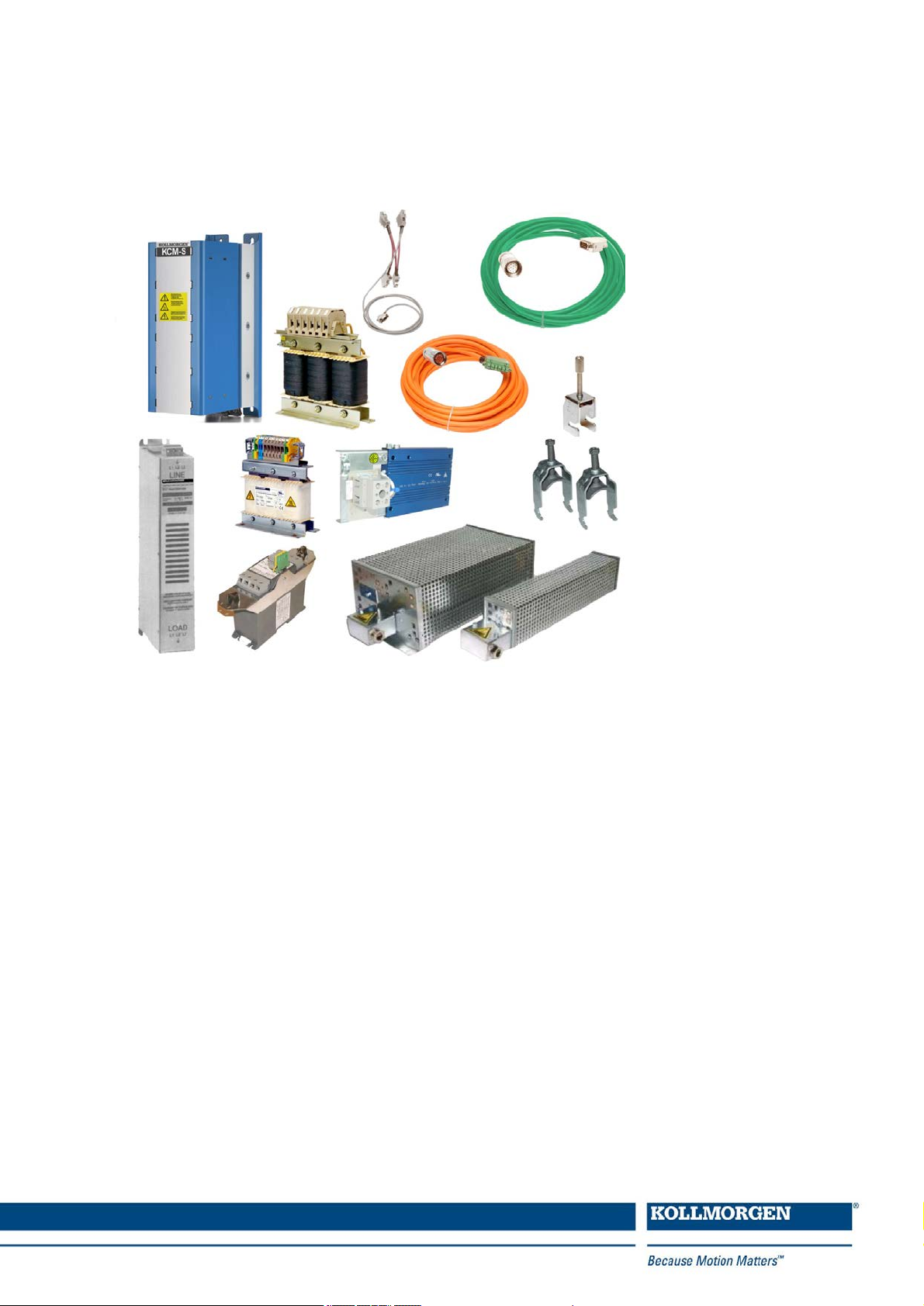
Accessories for digital drive systems
Manual
Edition: December 2014
Translation of the original document
European Version (CE region)
Keep all manuals as a product component during the life span of the product.
Pass all manuals to future users and owners of theproduct.
Record of Document Revisions
Edition Comments
04/2007 First edition
07/2007 System S700 updated.
11/2007 Several corrections, connectors added.
Motor cable 1mm² for S700 added, Symbols acc. to ANSI Z535, Y-Connector X0/X8 for S700
03/2008
04/2010
added, configuration of cables, 3YL20->3YL24.
Weight 3YL-24, Product brand, 3YL20 with UL, 3YLN new, S748/772, AKD, Resolver table,
S200 accessories removed.
Order codes brake resistors, Comcoder wire colors, feedback cable color, order codes motor
12/2010
cables, mains filter new types, mains chokes new types, transport tool for AKM8, mounting
clamps for S700, accessories S640/670 removed, 3YL20 removed, company name.
10/2011 Motor cables, cable data, EU order codes mating connectors AKD, AKD Hiperface.
Order codes motor cables S748/772 updated, cable data, combined cables for AKD with SFD,
03/2012
stainless steel connectors for Washdown motors.
SFD cable fotos, all SFD cables to one section, dimensions mains chokes corrected, capacitor
08/2012
modules new, formal improvements
Photos SFD cables, dimensions mains chokes updated, KCM modules new, manufacturing
hints for Kollmorgen cables removed, configured cable tables with photos, typo corrections, fan
05/2013
kit AKM7, mains filter 1NF-20 replaced by 1NF-20B, mounting clamps S700 removed, 24V
mains supply removed, hybrid cables new
11/2013
03/2014
05/2014
Heat sink AKD-N new, Hybrid cables AKD-C/N new, Hybrid cables SFD3/DSL, new Ethernet
cables
New Layout, AKMH mounting kit, KCM updated, AKM7 Fan-Kit updated, hybrid cables
SFD3/DSL added
Length definition of hybrid cables for decentralized systems changed, S700 X8Y set with
X4Amini
08/2014 Brake resistor AKD-x01206 changed, length definitions for decentral hybrid cables updated
12/2014 S640/670 added, AKD-x04807 accessories added
Technical changes which improve the performance of the device may be made without prior notice!
Printed in the United States of America
This document is the intellectual property of Kollmorgen. All rights reserved. No part of this work may be reproduced in any form (by photocopying, microfilm or any other method) or stored, processed, copied or distributed
by electronic means without the written permission of Kollmorgen.
2 Kollmorgen | December 2014

Accessories Europe | Table of Contents
1 Table of Contents
1 Table of Contents 3
2 General 7
2.1 About this manual 7
2.2 Hints for the online edition (PDF format) 7
2.3 Safety Notes 8
2.3.1 Symbols Used 8
2.3.2 You should pay attention to this 9
3 Digital Drive Systems 10
3.1 Drive System with S300 10
3.2 Drive System with S400 11
3.3 Drive System with S601...620 12
3.4 Drive System with S640...670 13
3.5 Drive System with S701...724 14
3.6 Drive System with S748/772 15
3.7 Drive System with AKD-x00306...02406 16
3.8 Drive System with AKD-x00307...02407 17
3.9 Drive System with AKD-x04807 18
3.10 Decentralized Drive System with AKD-C and AKD-N 19
4 Mechanical Accessories 20
4.1 Mounting Kit for AKMH Motors 20
4.2 Suspension Unit for AKM motors 20
4.3 Fan Kit for AKM7 motors 21
4.4 Mechanical accessories for AKD-N and AKD-C 22
4.4.1 Heat Sink forAKD-N 22
4.4.2 Mounting clamps forAKD-N 22
4.4.3 Sealing plugs for AKD-N connectors 23
4.4.4 Connector Kit forAKD-C 23
4.4.5 Cabinet connector coupling for AKD-C/N 23
5 Shield clamps 24
5.1 Auxiliary terminals on the servo amplifier 24
5.2 External shielding busbar 25
6 Mains chokes 26
6.1 General 26
6.2 Important notes 26
6.3 Type assignment and order codes 26
6.4 Mains choke 3L 27
7 Mains filters 28
7.1 General 28
7.2 Important notes 28
7.3 Type assignment and order codes 28
7.4 Mains filters 1NF-10...12 29
7.5 Mains filters 1NF-20B, 1NF-25 30
Kollmorgen | December 2014 3

Accessories Europe | Table of Contents
7.6 Mains filters 3NF-07...30 31
7.7 Mains filters 3EF-42...130 32
8 Brake resistors 33
8.1 General 33
8.2 Important notes 33
8.3 Type assignment and order codes 34
8.4 External brake resistor BAFP(U) 35
8.5 External brake resistor BAR(U) 36
8.6 External brake resistor BAS(U) 37
9 Capacitor Modules 38
9.1 General 38
9.2 Important notes 38
9.3 Type assignment and order codes 39
9.4 Example installation with AKD-P, KCM-P and KCM-E 39
9.5 KCM Module 40
10 Motor chokes 41
10.1 General 41
10.2 Important notes 42
10.3 Type assignment and order codes 42
10.4 Motor choke 3YL-24 43
10.5 Motor choke 3YLN-xx 44
11 Cables 45
11.1 Technical data for cables 45
11.2 Tools 45
11.3 PC connection 46
11.3.1 AKD 46
11.3.2 S300, S400, S600, S700 46
11.4 Power Voltage Supply, external brake resistor, DC bus link 48
11.4.1 Mating connector (part of delivery) 48
11.4.2 Mating connector (optional) 48
11.4.3 Recommended cable type 49
11.4.4 Preparingcables for AKD/S300/S400/S601...620/S700 49
11.4.5 Preparingcables for S640/670 and S748/772 51
11.5 24V auxiliary voltage supply 52
11.5.1 Mating connector (part of delivery) 52
11.5.2 Recommended cable type 52
11.5.3 Preparingcables 53
11.6 Digital/analog Inputs/Outputs 54
11.6.1 Digital In/Outputs for AKD-C 54
11.6.2 Digital In/Outputs for AKD-N 54
11.6.3 Digital/analog I/O for S300/S400/S600/S700 and AKD-B/P/T/M 55
11.6.4 Preparingcables 56
11.7 Encoder Emulation, Stepper motor control, Master-Slave 57
11.7.1 Mating connector, cable type 57
11.7.2 Connection 57
4 Kollmorgen | December 2014

Accessories Europe | Table of Contents
11.7.3 Termination resistors 57
11.7.4 Preparingcables 58
11.8 Ethernet cable 59
11.8.1 Order codes Ethernet cable, configured 59
11.9 CAN bus cable 60
11.9.1 CAN bus cable AKD 60
11.9.2 Can bus cable for S300/S400/S600/S700 60
11.10 Hybrid cables 62
11.10.1 AKD to AKM1 Motor (i-tec connector) 62
11.10.2 AKD to AKM2-6 (IP65 connector) 63
11.10.3 AKD-C to AKD-N in the decentralizeddrive system 65
11.10.4 AKD-N to AKD-N in the decentralizeddrive system 65
11.11 Motor cables 66
11.11.1 General 66
11.11.2 Motor cables, configured 66
11.11.2.1 Order codes motor cables for S300 67
11.11.2.2 Order codes motor cables for S400 67
11.11.2.3 Order codes motor cables for S601...620 68
11.11.2.4 Order codes motor cables for S701-712 69
11.11.2.5 Order codes motor cables for S724 70
11.11.2.6 Order codes motor cables for S748, S640/670 70
11.11.2.7 Order codes motor cables for AKD-B/P/T/M 72
11.11.2.8 Order codes motor cables for AKD-N 74
11.11.3 Preparing motorcables (motorend) 75
11.11.3.1 Motor series AKM2...8, 6SMx7, DBL2...6, DBK 75
11.11.3.2 Motor series AKM8, DBL7/8 75
11.11.4 Preparing motorcables (servo amplifier end) 77
11.11.4.1 Preparing cables for S300/S400 77
11.11.4.2 Preparing cables for S601...620 78
11.11.4.3 Preparing cables for S701...724 79
11.11.4.4 Preparing cables for AKD-x00306/x00606 79
11.11.4.5 Preparing cables for AKD-x01206/X02406/X0xx07 80
11.11.4.6 Preparing cables for S640/670 and S748/772 80
11.12 Feedback cables 82
11.12.1 Resolver cables 82
11.12.1.1 Resolver cables for S300/S400/S600/S700 82
11.12.1.2 Resolver cable for AKD 83
11.12.2 SFD cables for AKD 83
11.12.3 Encoder cables 84
11.12.3.1 Encoder cables for S300/S400/S600/S700 84
11.12.3.2 Encoder cables for AKD 85
11.12.4 ComCoder cables 86
11.12.4.1 ComCoder cables for S300/S400/S600/S700 86
11.12.4.2 Comcoder cables for AKD 87
Kollmorgen | December 2014 5

Accessories Europe | Table of Contents
This page intentionally left blank.
6 Kollmorgen | December 2014
2 General
2.1 About this manual
This manual describes accessories for Kollmorgen digital servo amplifiers. It contains essential technical data. The manual is only valid in conjunction with the instructions manual for
the servo amplifier and servo motor you are using in your application.
You will find copies of theinstructions manual for Kollmorgenservo amplifiers and servo
motors on the CD ROM included in the scope of supply and on our Internet site. The documents are available in Acrobat Reader format in multiple languages (system requirements:
WINDOWS, Internet browser, Acrobat Reader).
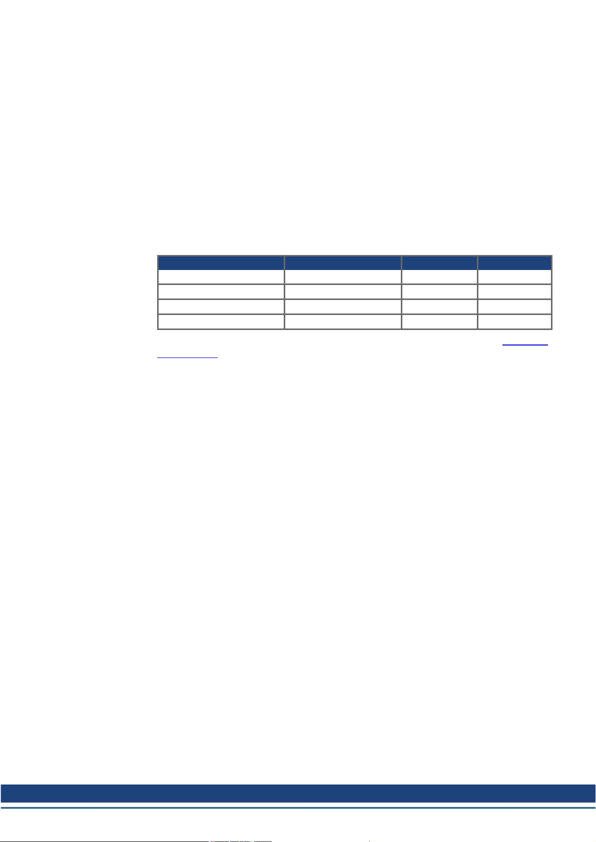
Servo amplifier product family names appear in abbreviated format:
Servo amplifier Abbreviation Servo amplifier Abbreviation
SERVOSTAR 300 S300 S701...724 S701...724
SERVOSTAR 400 S400 S748/772 S748/772
SERVOSTAR 601...620 S601...620 AKD-xyyyzz AKD
SERVOSTAR 640...670 S640...670
Accessories Europe | 2 General
More detail information can be found in the "European Product WIKI" available at www.wiki-
kollmorgen.eu.
2.2 Hints for the online edition (PDF format)
Bookmark:
Table of contents and index are active bookmarks.
Table of contents and index in the text:
The lines are active cross references. Click on the desired line and the appropriate page is
indicated.
Page/chapter numbers in the text:
Page/chapter numbers with cross references are active. Click at the page/chapter numberto
reach the indicated target.
Kollmorgen | December 2014 7
Accessories Europe | 2 General
2.3 Safety Notes
This section helps you to recognize and avoid dangers to people and objects.
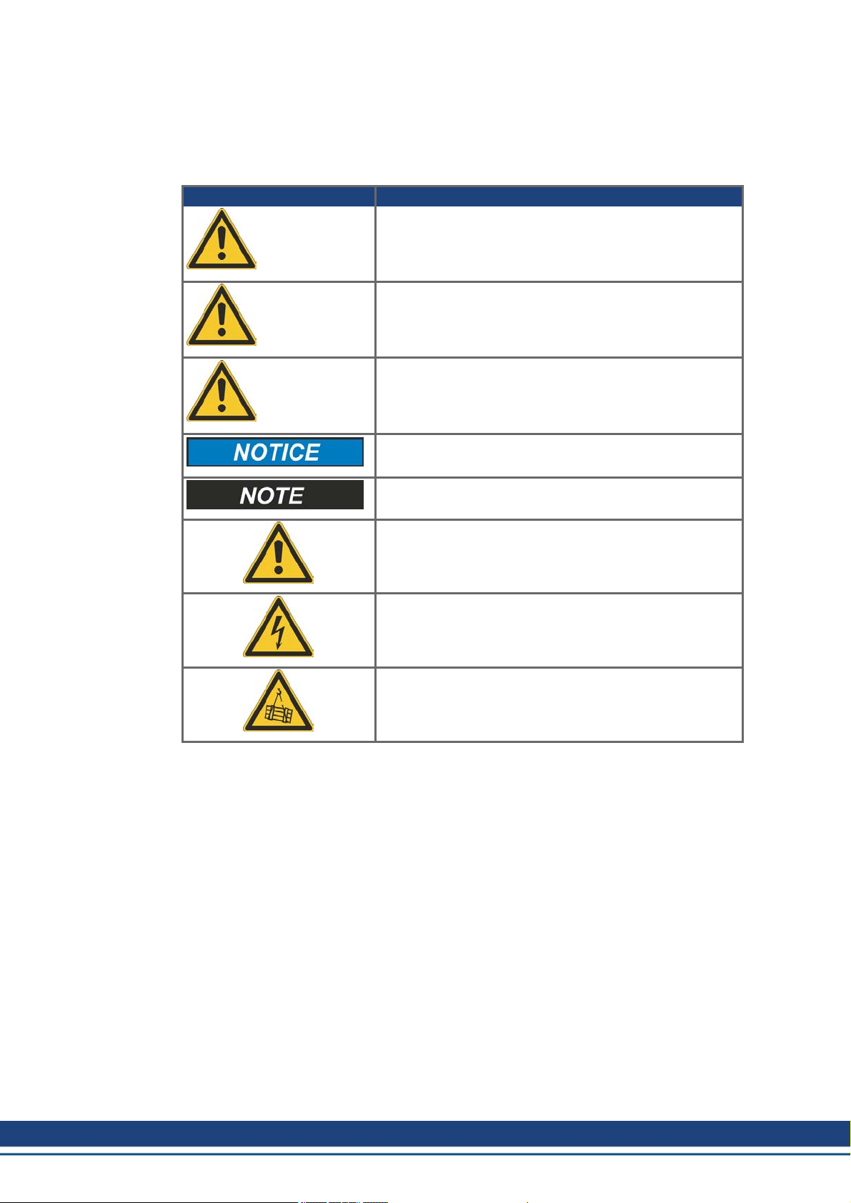
2.3.1 Symbols Used
Symbol Indication
Indicates a hazardous situation which, if not avoided, will
result in death or serious injury.
DANGER
Indicates a hazardous situation which, if not avoided, could
result in death or serious injury.
WARNING
Indicates a hazardous situation which, if not avoided, could
result in minor or moderate injury.
CAUTION
Indicates situations which, if not avoided, could result in
property damage.
This symbol indicates important notes.
Warning of a danger(general). The type of danger is specified by the text next to the symbol.
Warning of dangerfrom electricity and its effects.
Warning of suspended loads.
8 Kollmorgen | December 2014
2.3.2 You should pay attention to this
Read the documentation!
Read the available documentation before installation and commissioning. Improper handling
of the devices can cause harm to people or damage to property. The operator must therefore
ensure that all persons entrusted to work on the devices have read and understood the
manual and that the safety notices in this manual are observed.
Always observe the whole drive system built with servo amplifier, cables, motor, accessories (filters, chokes, etc.). This means, that all documentation which exist for the components, must be available, must be read and must be understood.
Pay attention to the technical data!
Adhere to the technical data and the specifications on connection conditions (ratingplate and
documentation). If permissible voltage values or current values are exceeded, the devices
can be damaged, e.g. through overheating.
Specialist staff required!
Only properly qualifiedpersonnel are permitted to perform such tasks as transport,
assembly, setup and maintenance. Qualified specialist staff are persons who are familiar
with the transport, installation, assembly, commissioning and operation of power electronics
andwho bringtheir relevant minimum qualifications to bear on their duties. The qualified personnel must know and observe IEC 60364 / IEC 60664 and national accident prevention regulations.
Additional requirements on specialist staff may also result from the risk assessment.
Hot surface!
Some devices can reach temperatures of up to 250°C during operation. Touching them can
result in burns. Observe the permissible mounting position and ensure that a sufficient distance is maintained from neighboring assemblies.
Accessories Europe | 2 General
Earthing!
It is vital that you ensure that the device housing is safely earthed to the PE (protective
earth) busbar in the switch cabinet. Without low-resistance earthing no personal protection
can be guaranteed and there is a risk of death from electric shock.
High voltages!
Keep the switching cabinet closed when the equipment is in operation. Not having optical displays does not guarantee an absence of voltage. Power connections may carry voltage even
if the motor is not turning.
Do not unplug any connectors during operation. There is a risk of death or severe injury from
touching exposed contacts. Power connections may be live even when the motor is not rotating. This can cause flashovers with resultinginjuries to persons and damage to the contacts.
DC Bus link connections can carry dangerous voltage levels over an hour after the line
voltage has been switched off (self-discharge time). Danger of death from electric shock.
Beforecommencing work on the modules’ power terminals, check the voltage at the connection terminals is de-energized to ground and to each other.
.
Kollmorgen | December 2014 9
Accessories Europe | 3 Digital Drive Systems
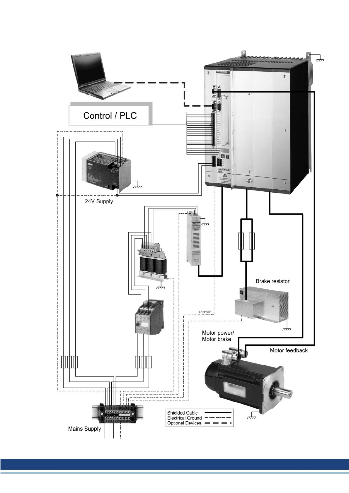
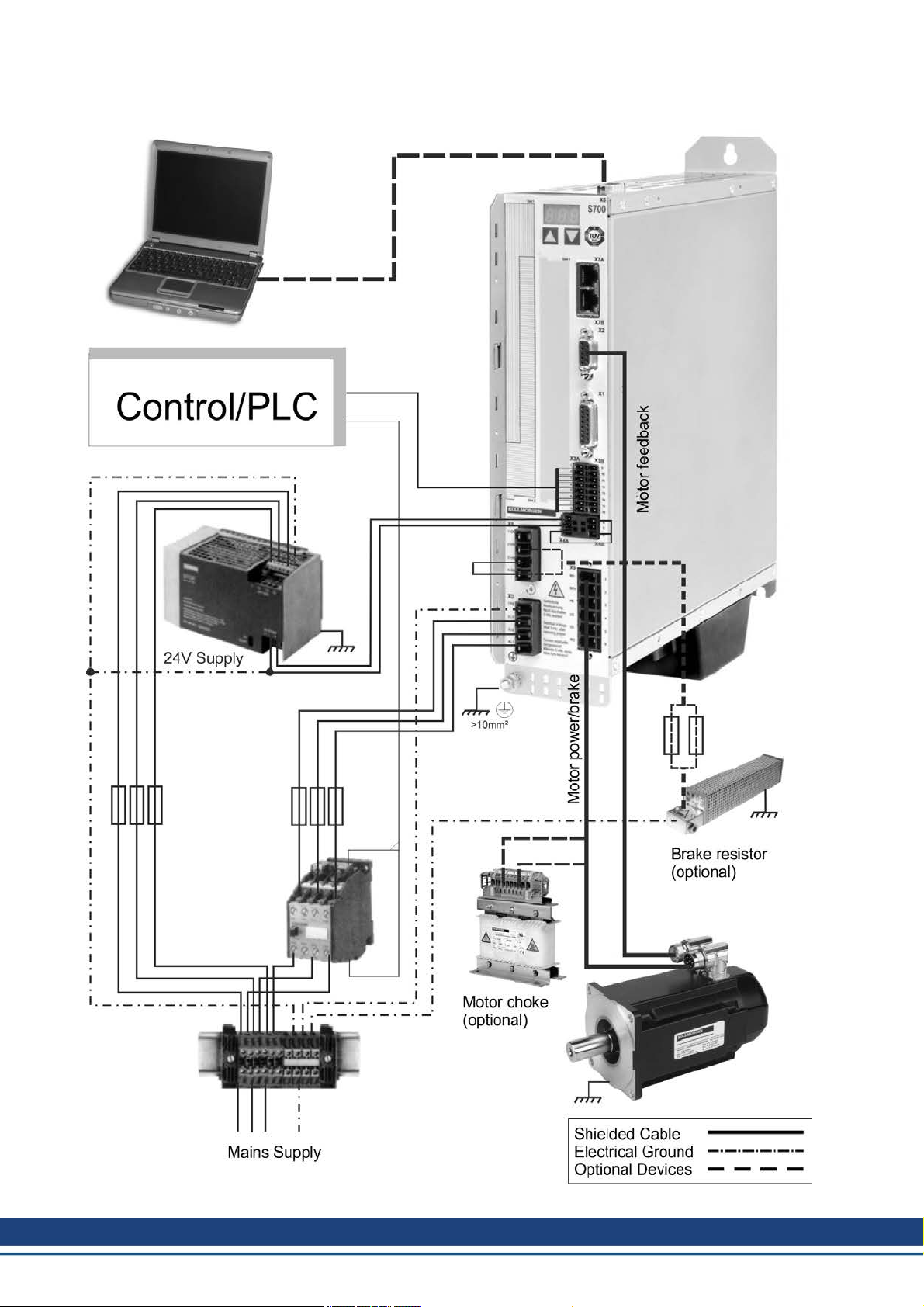
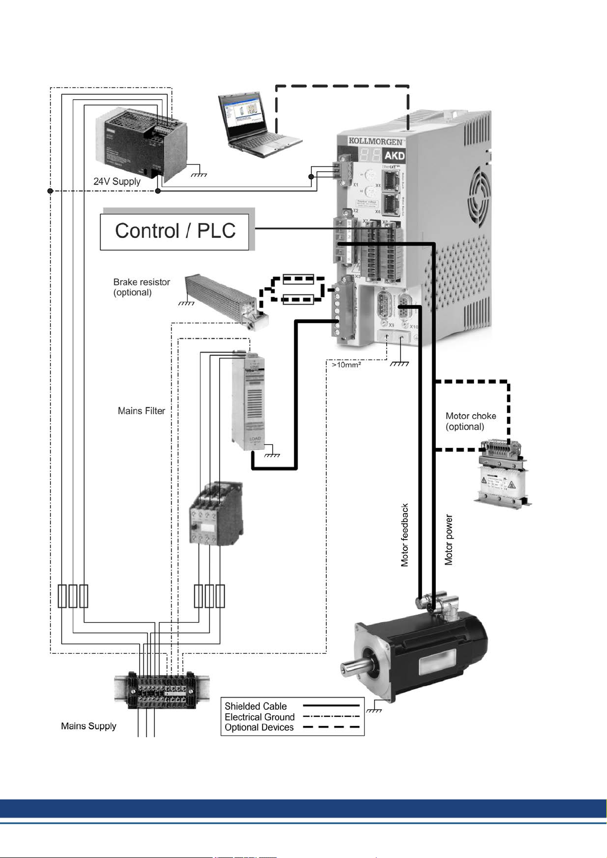
3 Digital Drive Systems
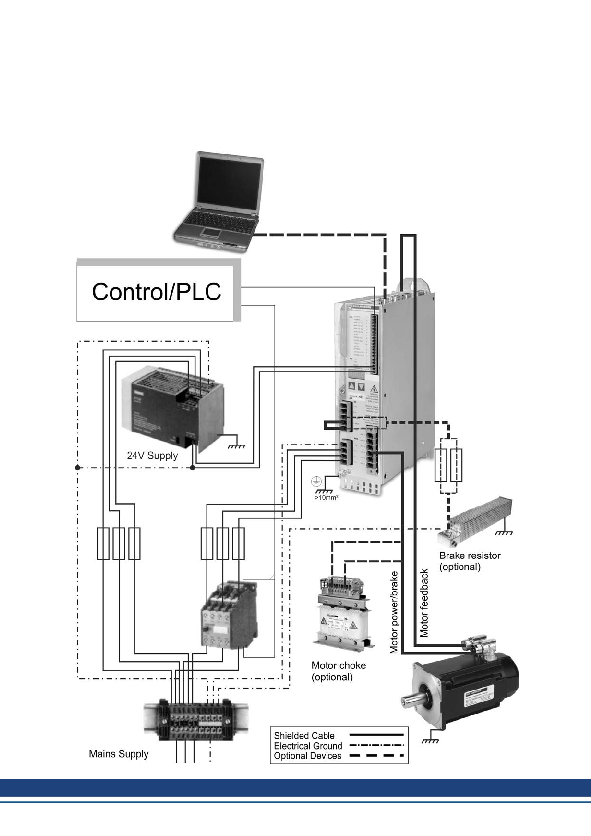
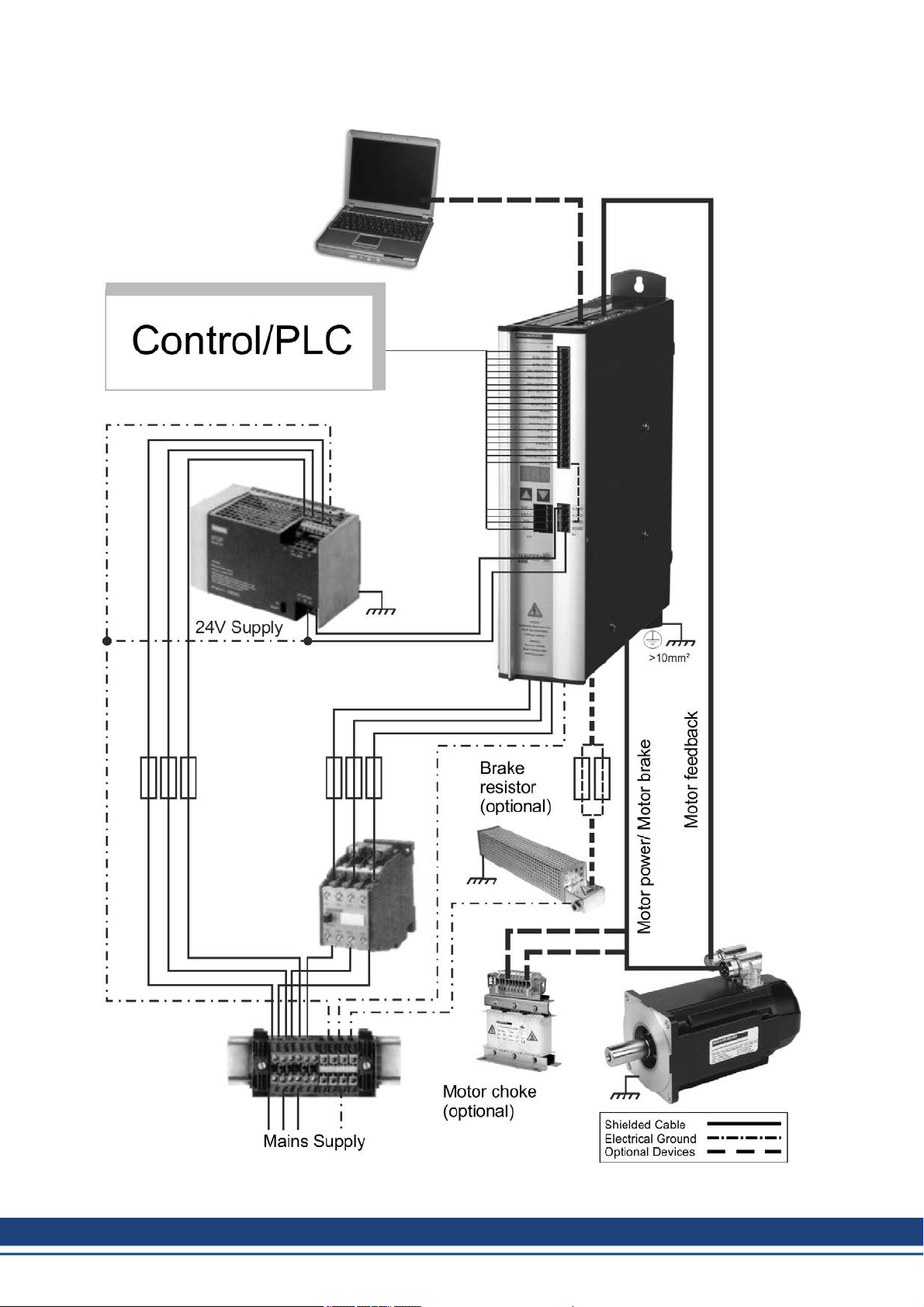
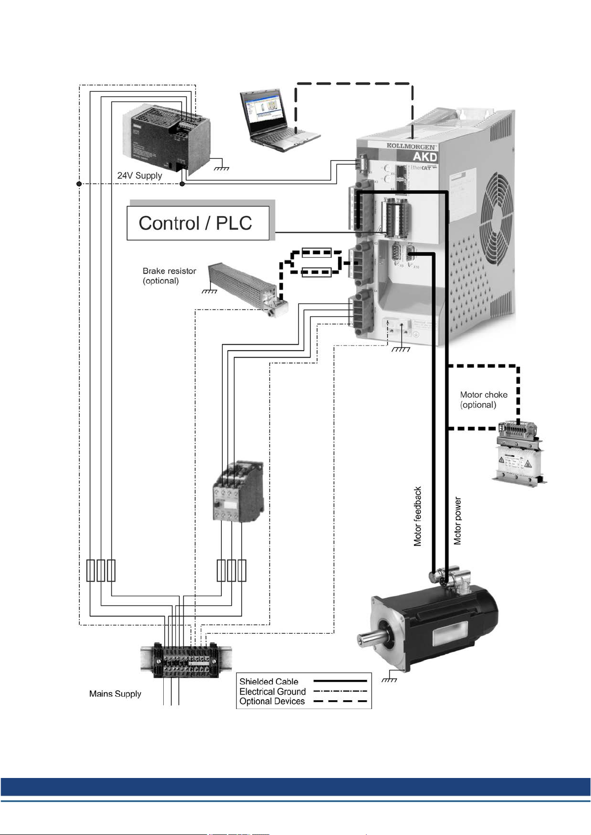
The systems shown are simply a possible scenario for setting up a digital drive system with
relevant servo amplifier components.
3.1 Drive System with S300
10 Kollmorgen | December 2014
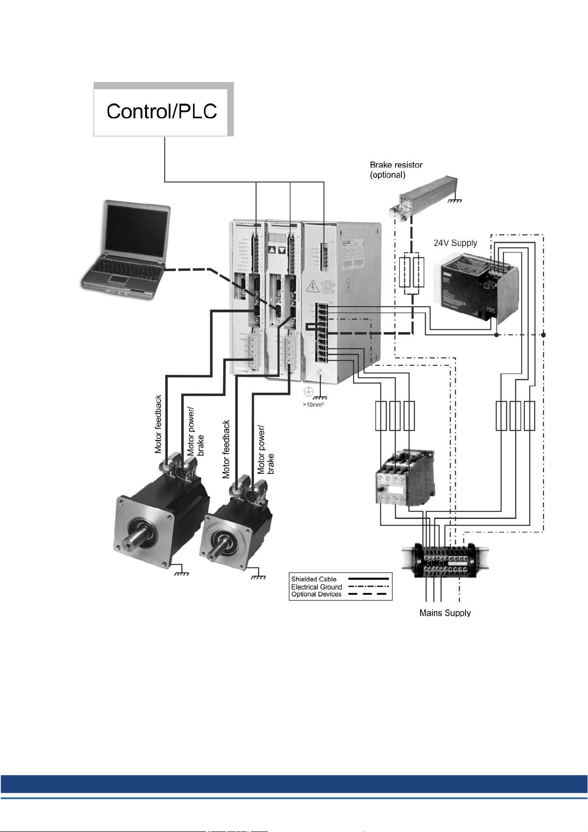
3.2 Drive System with S400
Accessories Europe | 3 Digital Drive Systems
Kollmorgen | December 2014 11
Accessories Europe | 3 Digital Drive Systems
3.3 Drive System with S601...620
12 Kollmorgen | December 2014
3.4 Drive System with S640...670
Accessories Europe | 3 Digital Drive Systems
Kollmorgen | December 2014 13
Accessories Europe | 3 Digital Drive Systems
3.5 Drive System with S701...724
14 Kollmorgen | December 2014
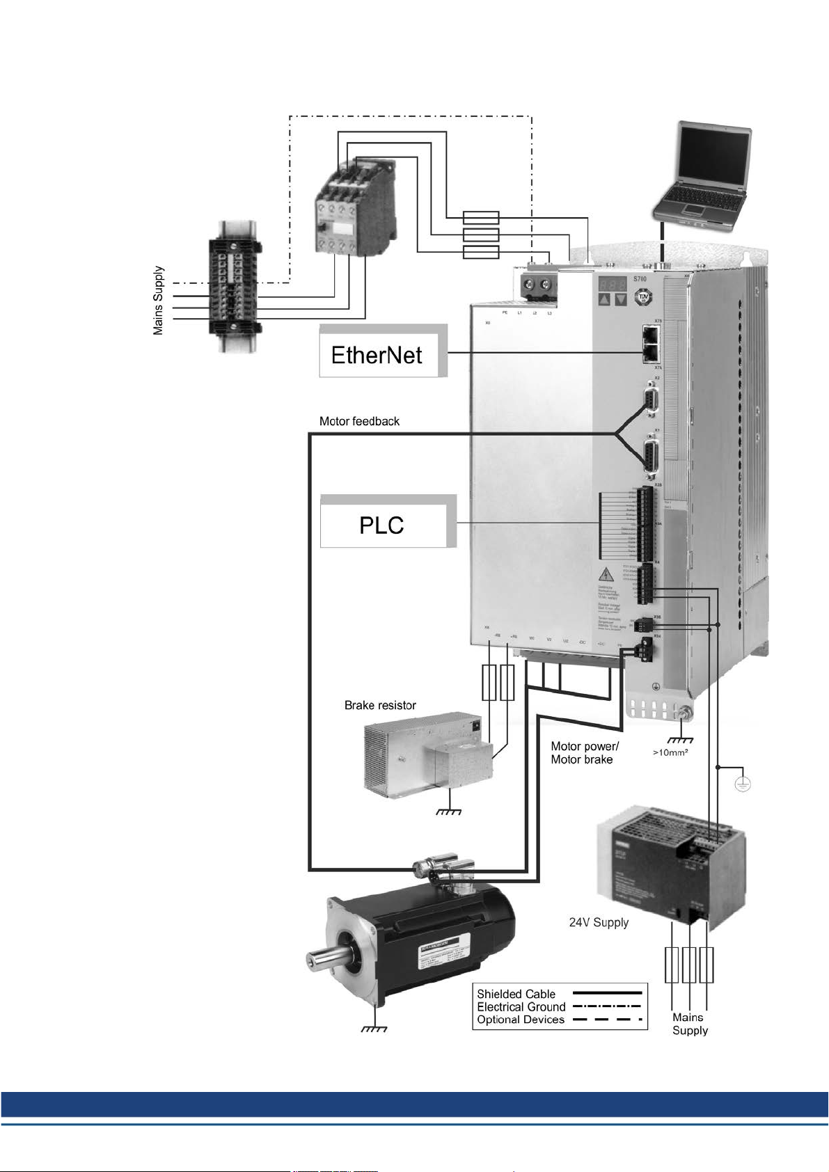
3.6 Drive System with S748/772
Accessories Europe | 3 Digital Drive Systems
Kollmorgen | December 2014 15
Accessories Europe | 3 Digital Drive Systems
3.7 Drive System with AKD-x00306...02406
16 Kollmorgen | December 2014
3.8 Drive System with AKD-x00307...02407
Accessories Europe | 3 Digital Drive Systems
Kollmorgen | December 2014 17

Accessories Europe | 3 Digital Drive Systems
3.9 Drive System with AKD-x04807
18 Kollmorgen | December 2014
Accessories Europe | 3 Digital Drive Systems
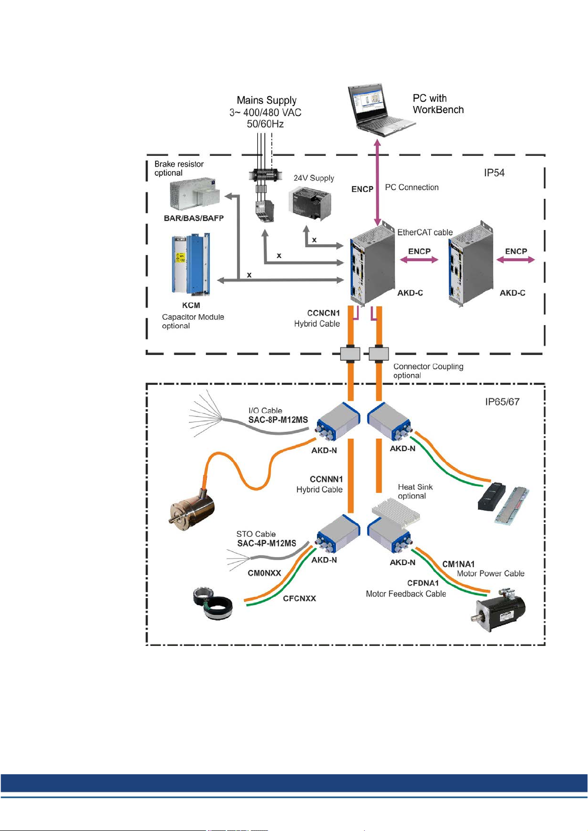
3.10 Decentralized Drive System with AKD-C and AKD-N
All components inside the borders aresuppliedby Kollmorgen with the exception of cables
signedwith "x". These cables are not suppliedby Kollmorgen, you should use cables or
wires according to EN 60204.
Kollmorgen | December 2014 19
Accessories Europe | 4 Mechanical Accessories
4 Mechanical Accessories
4.1 Mounting Kit for AKMH Motors
IEC mounting kits with 1 shaft center screw and 4 flangescrews. Hygienic mounting is possible only with these screws.
Description Order Code
Mounting Hardware AKMH2, Ax flange / Cx front mounting MTG-KIT-AKMH2-IEC
Mounting Hardware AKMH3, Ax flange / Cx front mounting MTG-KIT-AKMH3-IEC
Mounting Hardware AKMH4, Ax flange / Cx front mounting MTG-KIT-AKMH4-IEC
Mounting Hardware AKMH5, Ax flange / Cx front mounting MTG-KIT-AKMH5-IEC
Mounting Hardware AKMH6, Ax flange / Cx front mounting MTG-KIT-AKMH6-IEC
NEMA mounting kits are described in the US selection guide, available from the Kollmorgen
website www.kollmorgen.com).
4.2 Suspension Unit for AKM motors
DANGER
Suspended load. Risk of death if load falls. Never step under the load,
while the motor is raised!
You must read the instructions manual for the suspension unit ZPMZ 120/292. Observe the
"safety instructions" and "use as directed" hints before starting transportation work.
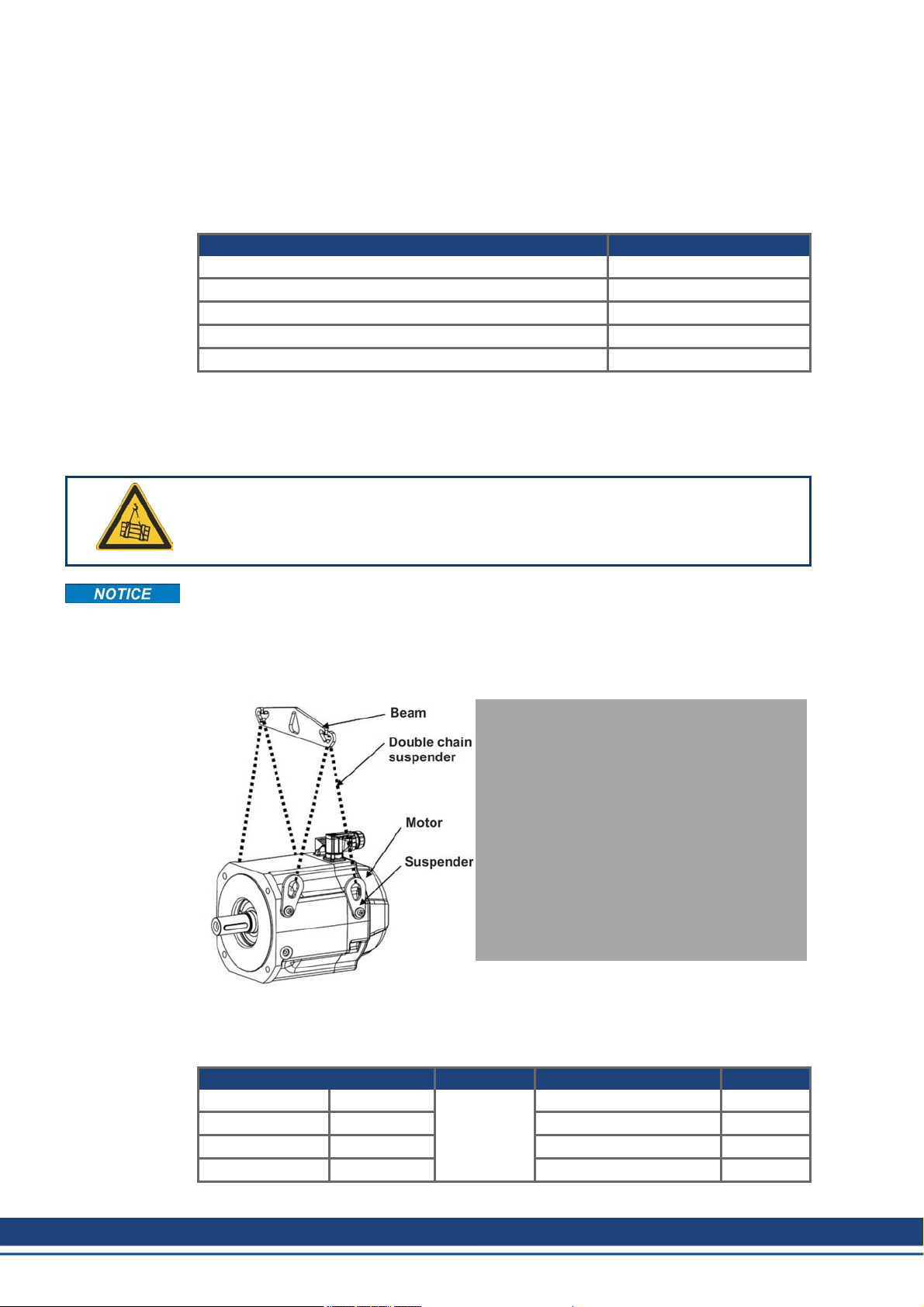
The Suspension Unit ZPMZ 120/292 is designed for suspended handlingexclusively of
motors (i.e., without attached units such as gearboxes, clutches, etc.) with a maximum
weight of 120 kg and maximum nominal span of the extreme suspension hooks of 292 mm.
The suspended unit consists of a Beam, suspended off the crane hook and two double-run
chain suspenders. The motormay be borne on two or four runs of thechain suspender.
The suspenders (number depends on the motor type) are delivered with the motor.
Technical Data
Lifting capacity 120kg Weight 0,83 kg
Nominal span 292 mm Number of cycles a year 20.000
Lugwidth 44,7 mm Average load 60 %
Lugheight 51 mm Order code FA00092
20 Kollmorgen | December 2014

4.3 Fan Kit for AKM7 motors
Observe the mounting instructions delivered with the fankit. The fan housing can be mounted either with both the supplied brackets andspacers or with the brackets only. The choice
of mounting method depends on the application. If strong vibrations are expected, you should
use both brackets and spacers. Motors with integrated brakes require the longs spacers.
Mounting the fan kit enlarges the motor by approximately 65 mm. The detailed final dimensions of AKM7 motors with mounted fan kit can be found in the instructions manual of the
AKM motor series. Ventilation of AKM7 motors allow increased current of the motors. This
higher current usually requires larger wiring cross section compared to not ventilated motors.
The necessary data for current and wiring cross section can be found in the technical data
section of the AKM instructions manual.
Technical Data
Supply voltage 24 VDC
Supply current 270mA
Electrical power 6.5 W
Surface Coated with polyester powder coating in matt black, not resistant
Protection class IP 20
Connection Cable gland 10 mm, cable diameter 4 mm to 6 mm, recommended cable
Terminals 0.33 mm² to 4 mm²
Weight 2.52 kg
Order code AKM7-FAN
Accessories Europe | 4 Mechanical Accessories
against solvents
3x0.75 mm² (not part of delivery)
Kollmorgen | December 2014 21
Accessories Europe | 4 Mechanical Accessories
4.4 Mechanical accessories for AKD-N and AKD-C
You must read the AKD-N/AKD-C installation manuals. Observe the safety instructions
given there before commencing mounting/installation work.
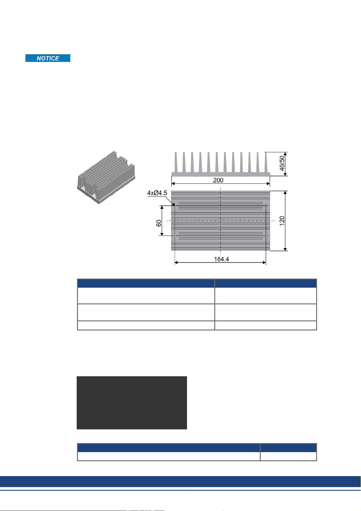
4.4.1 Heat Sink for AKD-N
When mounting AKD-N to themachinery, temperature management is important to ensure
maximum performance of the drive system. In case of medium or bad cooling situation (as
described in the AKD-N Installation Manual), youcan mount a heat sink to the AKD-N.
Heat flow is optimized by a heat conducting film, which must be placed between heat sink
andAKD-N.
Mounting holes in the heat sink and winding holes in the AKD-N are prepared for M4x16
hexagon socket screws to ISO 4762. Use a 3 mm T-handle Allen key for mounting.
Order Codes
Article Order codes
Heat sink Kit 40 mm with Heat conducting film and
4 screws M4x16
Heat sink Kit 50 mm with Heat conducting film and
4 screws M4x16
Heat conducting film 849-373000-04
4.4.2 Mounting clamps for AKD-N
The AKD-N servo amplifier is mounted to the machine with special mounting clamps. The
delivery package contains 4 clamps. In case of lost or damaged clamps, you can ordera set
of four clamps.
Order Codes
Article Order codes
AKD-N Mounting Clamps Set, 4 clamps AKD-N-M/C-Set
AKD-N 3,6 HEATSINK KIT 40MM
AKD-N 3,6 HEATSINK KIT 50MM
22 Kollmorgen | December 2014
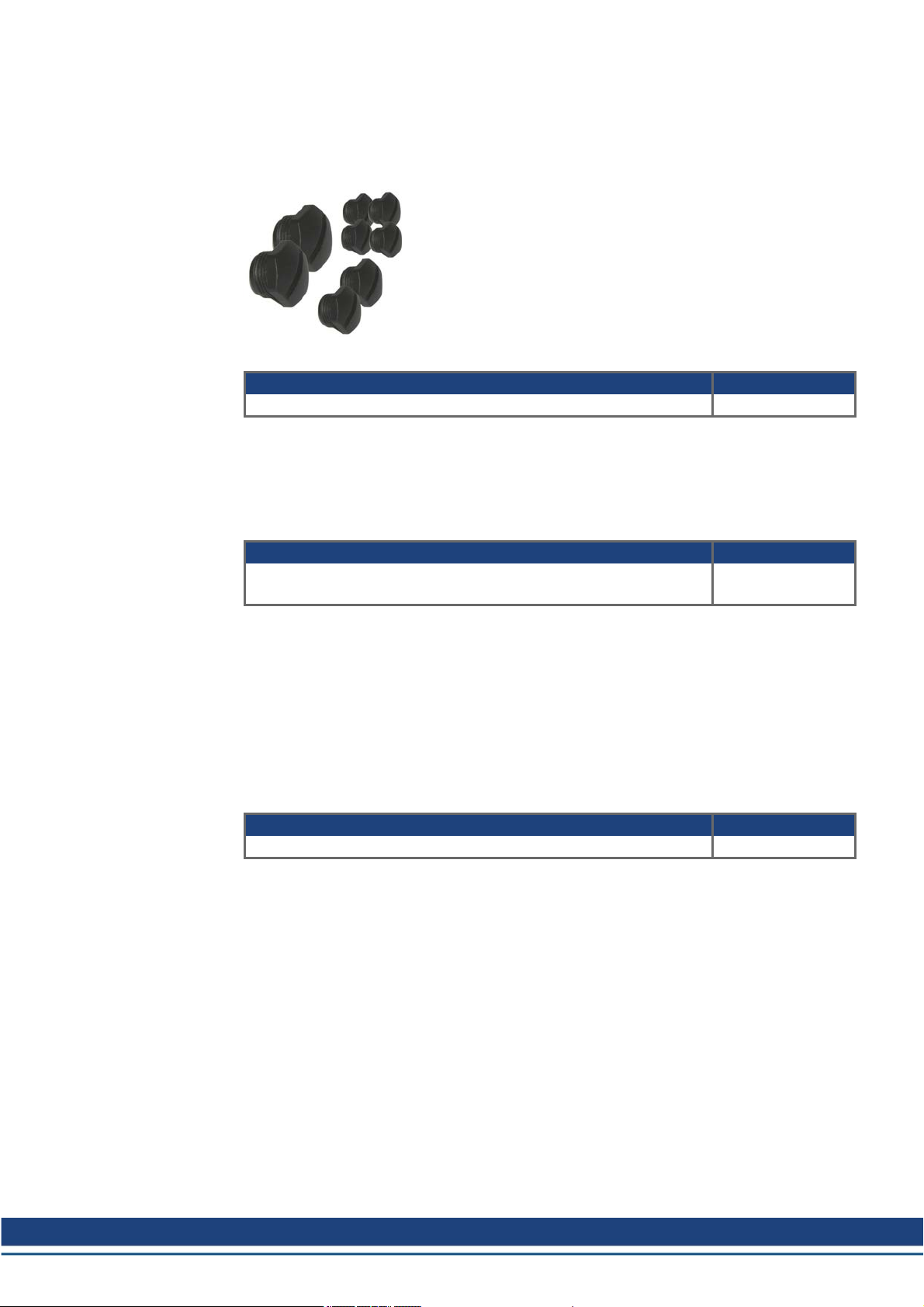
4.4.3 Sealing plugs for AKD-N connectors
The sealing plugs in the delivery package are screwed to unused AKD-N connectors to
ensure the IP class for the machine environment. In case of lost plugs, you can order a set
with 3 different plug sizes.
Order Code
Article Order Codes
AKD-N Sealing Plug Set, 4xM12, 2xM23, 2xM17 AKD-N-S/P-Set
4.4.4 Connector Kit for AKD-C
Mating connectors X12, X13, X14, X15, and X17 are part of delivery. If a mating connector is
lost or damaged, you can order the AKD-C Connector Kit.
Order Code
Accessories Europe | 4 Mechanical Accessories
Article Order Codes
AKD-N Connector Kit, included matingconnectors X12, X13, X14,
X15, and X17
4.4.5 Cabinet connector coupling for AKD-C/N
The connector couplingmust be built into the outer wall of a cabinet. The connector coupling
connects powerand signal lines as well as shielding of the hybrid cables and ensures the
long-term sealed transition between cabinet environment (IP54) and machine environment
(IP65/67).
Inside the cabinet the CCNCN1 cable (➜ p. 65) to AKD-C can be plugged in, outside the
cabinet the CCNNN1 cable (➜ p. 65) to AKD-N can be plugged in.
Order Codes
Article Order Codes
Hybrid Connector Coupling AKD-C/AKD-N AKD-CN-Coupling*
*in process
AKD-C-CONKIT
Kollmorgen | December 2014 23
Accessories Europe | 5 Shield clamps
5 Shield clamps
You must read the instructions manuals for the servo amplifier/servo motor you areusing in
your application. Observe the safety instructions they contain before commencing mounting/installation work.
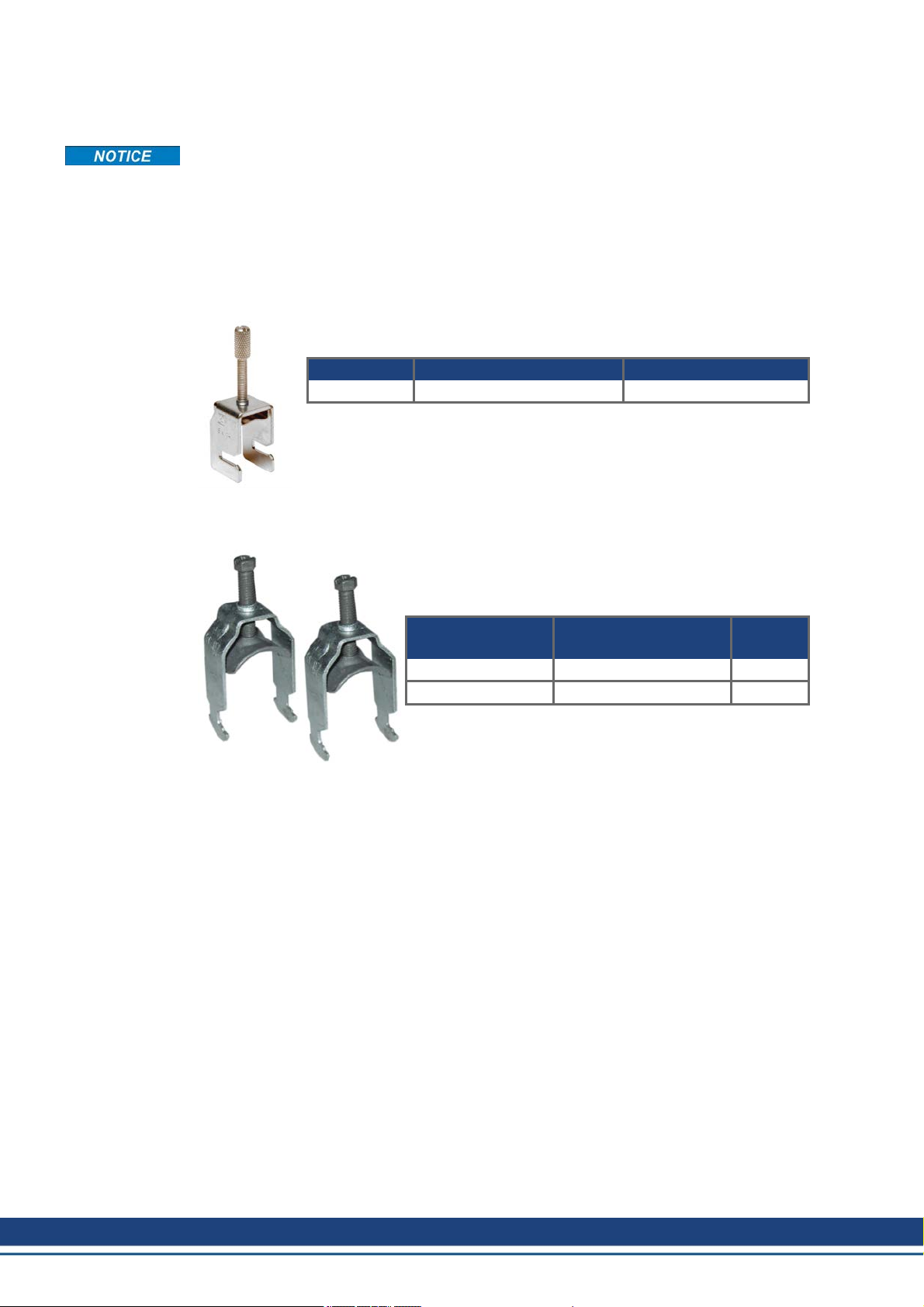
5.1 Auxiliary terminals on the servo amplifier
S300, S701...724 and AKD
These servo amplifiers feature slots on the front panel for the connection of
additional shield clamps.
Article Tension range Order Codes
SK14 6-13mm DE-108248
S640/670, S748/772
The shroud supplied with these servo amplifiers features
slots for the connection of additional shield clamps.
We recommend using the following shield clamp:
Manufacturer Article Tension
range
OBO (Bettermann) BBS-Schelle Typ 2056 16-22mm
OBO (Bettermann) BBS-Schelle Typ 2056 28-34mm
The clamps are part of delivery of the servo amplifier.
24 Kollmorgen | December 2014
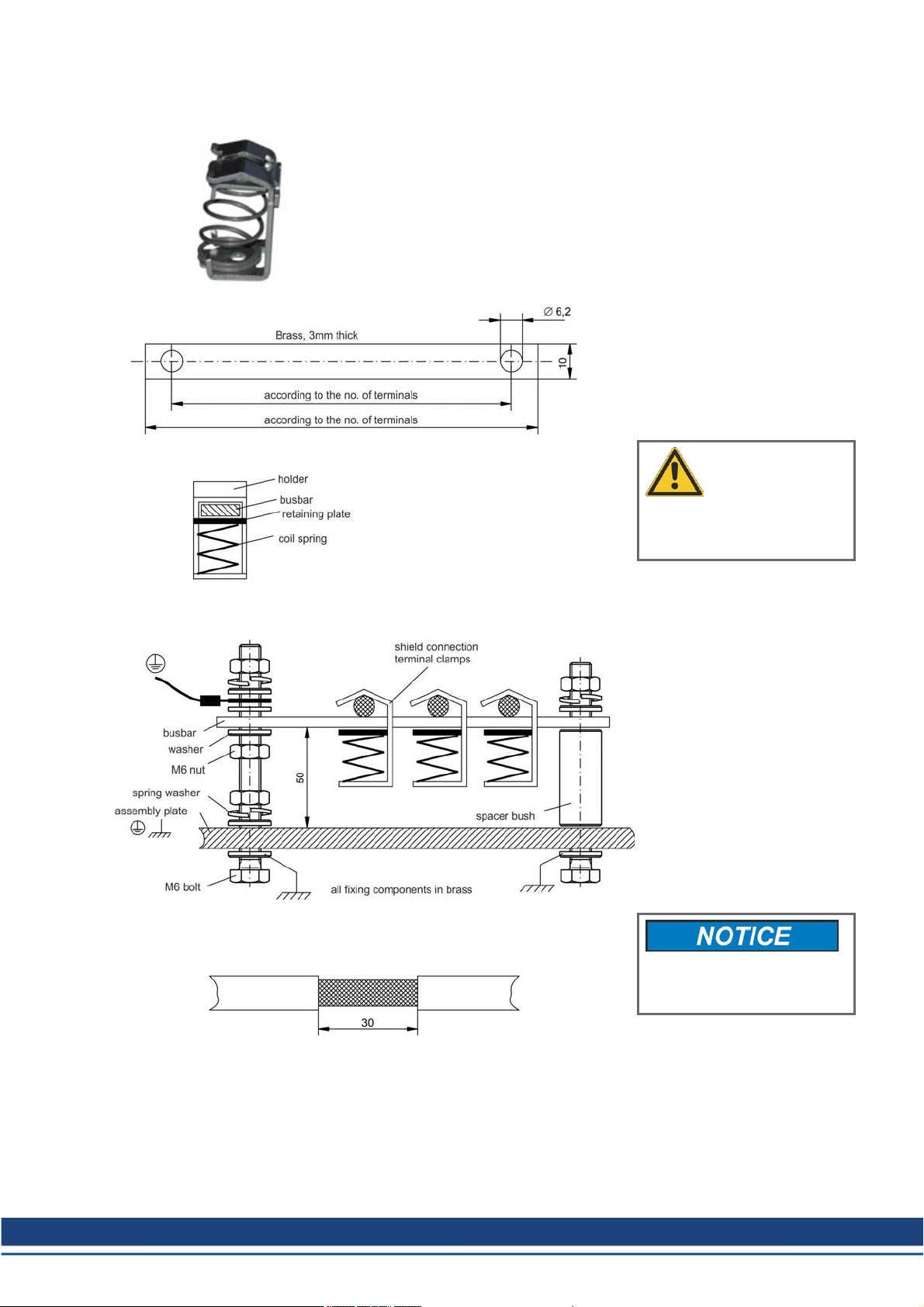
5.2 External shielding busbar
Accessories Europe | 5 Shield clamps
The power cable shields (line in, motor cable, external regen resistor)
can be routed to an additional busbar via shield clamps.
Kollmorgen recommends using Weidmüller KLBÜ shield clamps.
A possible scenario for setting up a busbar for the above shield
clamps is described below.
1. Cut a busbar of the required
length from a brass rail (cross-section 10 x 3 mm) and drill holes in it
as indicated. All shield clamps
required must fit between the drill
holes.
CAUTION
Risk of injury due to the spring
force of the coil spring. Use pincers.
2. Squeeze together the coil
spring and the supporting plate
and push the busbar through the
opening in the holder.
3. Mount the busbar with the
shield clamps fitted on the
assembly plate. Use either metal
spacer bushes or screws with nuts
and accessories to maintain a spacing of 50 mm. Earth the busbar
using a single conductor with a
cross-section of at least 2.5mm².
4. Strip the external cable sheath
to a length of approximately 30
mm, taking care not to damage
the braided shield. Push the
shield clamp up and route the
cable to it via the busbar.
Make sure there is good contact between the shield clamp
and the braided shield.
Kollmorgen | December 2014 25
Accessories Europe | 6 Mains chokes
6 Mains chokes
You must read the instructions manuals for the servo amplifier and servo motoryou are using
in your application. Observe the safety instructions given there.
6.1 General
A 3L mains choke must be used on S640/670 servo amplifiers in order to reduce mains harmonics.
In special cases, if mains voltage is more than3% asymmetrical, then the S748/772 must be
used with a mains choke. In unfavorable combination of mains impedance and DC bus capacitance the unloaded DC bus may reach voltage up to 800V without choke. For EMC reasons
the chokes should be mounted isolatedto the cabinet. Single conductors can be used for wiring, shielded cables are not required. More information seeWIKI "Mains Choke".
Purpose of mains choke:
l Prevents impermissible loading of semiconductors in the event of rapid current rise during
commutation.
l Prevents voltage dips in the mains voltage causedby commutation.
l Reduces current ripple in the DC link, thereby increasing the service life of the DC link
capacitors.
6.2 Important notes
DANGER
Power terminals are capable of conducting hazardous voltage up to
10minutes after the mains voltage has been disconnected. Risk of electric shock. Before starting work on power terminals, check that the phaseto-earth and phase-to-phase voltages have de-energised.
Due to the high earth leakage currents induced by the system, you should observe the
requirements of EN 61800-5-1 (e.g. fixed installation, ≥ 10 mm² or double protective earth)
when carrying out mounting and installationwork. You must read the instructions manual for
the servo amplifier/servo motor you are using in your application and observe the safety
instructions they contain before commencing mounting/installation work.
Mounting: 50mm free space required above and below the device.
Connection diagram: see servo amplifier instructions manual.
6.3 Type assignment and order codes
Servo amplifier Mains choke
S640/670 (with asymmetrical mains >3% only) 4% uk
S748/772 (with asymmetrical mains >3% only) 2% uk
AKD, S300, S400, S601...620, S701...724 not required
Order Codes
Article uk Order codes
Mains choke 3L0,5-63-4 (0.47mH, 63A) 4% DE-92201
Mains choke 3L0,4-80-4 (0.37mH, 80A) 4% DE-92100
Mains choke 3L0,2-160-4 (0.19mH, 160A) 4% DE-92099
Mains choke 3L0,24-50-2 (0.24mH, 50A) 2% DE-201476
Mains choke 3L0,2-75-2 (0.20mH, 75A) 2% DE-201477
26 Kollmorgen | December 2014

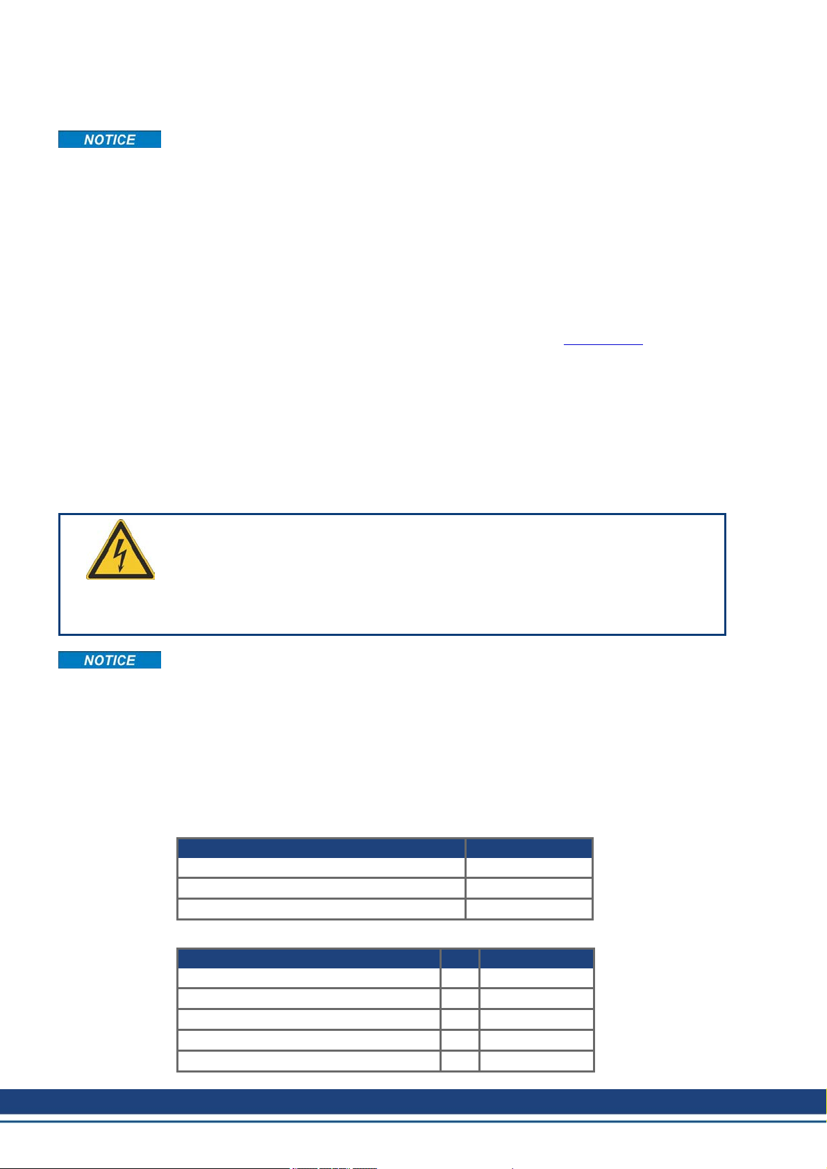
6.4 Mains choke 3L
A number of servo amplifiers can be connected to one and the same mains choke; the rated
current of the mains choke must be greater than or at least equal to the total current of the
connected servo amplifiers.
Accessories Europe | 6 Mains chokes
Photo: 3L0,2-160-4, all models
are similar
Technical Data
Inducti-
Type [mH] [A] [%] [mm] [mm] [mm] [mm] [mm] [mm] [mm²] [kg]
3L 0,5-63-4 0.47 63 4 185 170 77 122 215 8x12 16 9.65
3L 0,4-80-4 0.37 80 4 210 175 85 125 240 8x12 16 12.5
3L 0,2-160-4 0.19 160 4 291 273 116.5 148.5 310 10x18 95 27
3L 0,24-50-2 0.24 50 2 152.5 114.3 88.9 114.3 163 6.5 10 5.9
3L 0,2-75-2 0.20 75 2 185 170 77 122 220 8x12 35 9.9
vity
Nominal
Current
uk A B C D E F Termi-
nals
Weight
Kollmorgen | December 2014 27
 Loading...