

Kollmorgen SERVOSTAR 300, SERVOSTAR 400, SERVOSTAR 601, SERVOSTAR 640, SERVOSTAR 620 User Manual
...Page 1
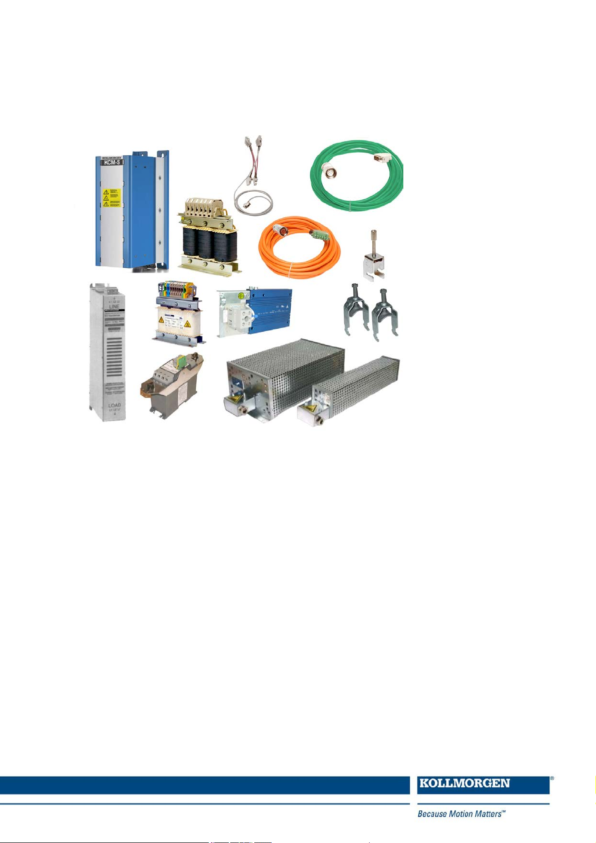
Accessories for digital drive systems
Manual
Edition: December 2014
Translation of the original document
European Version (CE region)
Keep all manuals as a product component during the life span of the product.
Pass all manuals to future users and owners of theproduct.
Page 2
Record of Document Revisions
Edition Comments
04/2007 First edition
07/2007 System S700 updated.
11/2007 Several corrections, connectors added.
Motor cable 1mm² for S700 added, Symbols acc. to ANSI Z535, Y-Connector X0/X8 for S700
03/2008
04/2010
added, configuration of cables, 3YL20->3YL24.
Weight 3YL-24, Product brand, 3YL20 with UL, 3YLN new, S748/772, AKD, Resolver table,
S200 accessories removed.
Order codes brake resistors, Comcoder wire colors, feedback cable color, order codes motor
12/2010
cables, mains filter new types, mains chokes new types, transport tool for AKM8, mounting
clamps for S700, accessories S640/670 removed, 3YL20 removed, company name.
10/2011 Motor cables, cable data, EU order codes mating connectors AKD, AKD Hiperface.
Order codes motor cables S748/772 updated, cable data, combined cables for AKD with SFD,
03/2012
stainless steel connectors for Washdown motors.
SFD cable fotos, all SFD cables to one section, dimensions mains chokes corrected, capacitor
08/2012
modules new, formal improvements
Photos SFD cables, dimensions mains chokes updated, KCM modules new, manufacturing
hints for Kollmorgen cables removed, configured cable tables with photos, typo corrections, fan
05/2013
kit AKM7, mains filter 1NF-20 replaced by 1NF-20B, mounting clamps S700 removed, 24V
mains supply removed, hybrid cables new
11/2013
03/2014
05/2014
Heat sink AKD-N new, Hybrid cables AKD-C/N new, Hybrid cables SFD3/DSL, new Ethernet
cables
New Layout, AKMH mounting kit, KCM updated, AKM7 Fan-Kit updated, hybrid cables
SFD3/DSL added
Length definition of hybrid cables for decentralized systems changed, S700 X8Y set with
X4Amini
08/2014 Brake resistor AKD-x01206 changed, length definitions for decentral hybrid cables updated
12/2014 S640/670 added, AKD-x04807 accessories added
Technical changes which improve the performance of the device may be made without prior notice!
Printed in the United States of America
This document is the intellectual property of Kollmorgen. All rights reserved. No part of this work may be reproduced in any form (by photocopying, microfilm or any other method) or stored, processed, copied or distributed
by electronic means without the written permission of Kollmorgen.
2 Kollmorgen | December 2014
Page 3

Accessories Europe | Table of Contents
1 Table of Contents
1 Table of Contents 3
2 General 7
2.1 About this manual 7
2.2 Hints for the online edition (PDF format) 7
2.3 Safety Notes 8
2.3.1 Symbols Used 8
2.3.2 You should pay attention to this 9
3 Digital Drive Systems 10
3.1 Drive System with S300 10
3.2 Drive System with S400 11
3.3 Drive System with S601...620 12
3.4 Drive System with S640...670 13
3.5 Drive System with S701...724 14
3.6 Drive System with S748/772 15
3.7 Drive System with AKD-x00306...02406 16
3.8 Drive System with AKD-x00307...02407 17
3.9 Drive System with AKD-x04807 18
3.10 Decentralized Drive System with AKD-C and AKD-N 19
4 Mechanical Accessories 20
4.1 Mounting Kit for AKMH Motors 20
4.2 Suspension Unit for AKM motors 20
4.3 Fan Kit for AKM7 motors 21
4.4 Mechanical accessories for AKD-N and AKD-C 22
4.4.1 Heat Sink forAKD-N 22
4.4.2 Mounting clamps forAKD-N 22
4.4.3 Sealing plugs for AKD-N connectors 23
4.4.4 Connector Kit forAKD-C 23
4.4.5 Cabinet connector coupling for AKD-C/N 23
5 Shield clamps 24
5.1 Auxiliary terminals on the servo amplifier 24
5.2 External shielding busbar 25
6 Mains chokes 26
6.1 General 26
6.2 Important notes 26
6.3 Type assignment and order codes 26
6.4 Mains choke 3L 27
7 Mains filters 28
7.1 General 28
7.2 Important notes 28
7.3 Type assignment and order codes 28
7.4 Mains filters 1NF-10...12 29
7.5 Mains filters 1NF-20B, 1NF-25 30
Kollmorgen | December 2014 3
Page 4

Accessories Europe | Table of Contents
7.6 Mains filters 3NF-07...30 31
7.7 Mains filters 3EF-42...130 32
8 Brake resistors 33
8.1 General 33
8.2 Important notes 33
8.3 Type assignment and order codes 34
8.4 External brake resistor BAFP(U) 35
8.5 External brake resistor BAR(U) 36
8.6 External brake resistor BAS(U) 37
9 Capacitor Modules 38
9.1 General 38
9.2 Important notes 38
9.3 Type assignment and order codes 39
9.4 Example installation with AKD-P, KCM-P and KCM-E 39
9.5 KCM Module 40
10 Motor chokes 41
10.1 General 41
10.2 Important notes 42
10.3 Type assignment and order codes 42
10.4 Motor choke 3YL-24 43
10.5 Motor choke 3YLN-xx 44
11 Cables 45
11.1 Technical data for cables 45
11.2 Tools 45
11.3 PC connection 46
11.3.1 AKD 46
11.3.2 S300, S400, S600, S700 46
11.4 Power Voltage Supply, external brake resistor, DC bus link 48
11.4.1 Mating connector (part of delivery) 48
11.4.2 Mating connector (optional) 48
11.4.3 Recommended cable type 49
11.4.4 Preparingcables for AKD/S300/S400/S601...620/S700 49
11.4.5 Preparingcables for S640/670 and S748/772 51
11.5 24V auxiliary voltage supply 52
11.5.1 Mating connector (part of delivery) 52
11.5.2 Recommended cable type 52
11.5.3 Preparingcables 53
11.6 Digital/analog Inputs/Outputs 54
11.6.1 Digital In/Outputs for AKD-C 54
11.6.2 Digital In/Outputs for AKD-N 54
11.6.3 Digital/analog I/O for S300/S400/S600/S700 and AKD-B/P/T/M 55
11.6.4 Preparingcables 56
11.7 Encoder Emulation, Stepper motor control, Master-Slave 57
11.7.1 Mating connector, cable type 57
11.7.2 Connection 57
4 Kollmorgen | December 2014
Page 5

Accessories Europe | Table of Contents
11.7.3 Termination resistors 57
11.7.4 Preparingcables 58
11.8 Ethernet cable 59
11.8.1 Order codes Ethernet cable, configured 59
11.9 CAN bus cable 60
11.9.1 CAN bus cable AKD 60
11.9.2 Can bus cable for S300/S400/S600/S700 60
11.10 Hybrid cables 62
11.10.1 AKD to AKM1 Motor (i-tec connector) 62
11.10.2 AKD to AKM2-6 (IP65 connector) 63
11.10.3 AKD-C to AKD-N in the decentralizeddrive system 65
11.10.4 AKD-N to AKD-N in the decentralizeddrive system 65
11.11 Motor cables 66
11.11.1 General 66
11.11.2 Motor cables, configured 66
11.11.2.1 Order codes motor cables for S300 67
11.11.2.2 Order codes motor cables for S400 67
11.11.2.3 Order codes motor cables for S601...620 68
11.11.2.4 Order codes motor cables for S701-712 69
11.11.2.5 Order codes motor cables for S724 70
11.11.2.6 Order codes motor cables for S748, S640/670 70
11.11.2.7 Order codes motor cables for AKD-B/P/T/M 72
11.11.2.8 Order codes motor cables for AKD-N 74
11.11.3 Preparing motorcables (motorend) 75
11.11.3.1 Motor series AKM2...8, 6SMx7, DBL2...6, DBK 75
11.11.3.2 Motor series AKM8, DBL7/8 75
11.11.4 Preparing motorcables (servo amplifier end) 77
11.11.4.1 Preparing cables for S300/S400 77
11.11.4.2 Preparing cables for S601...620 78
11.11.4.3 Preparing cables for S701...724 79
11.11.4.4 Preparing cables for AKD-x00306/x00606 79
11.11.4.5 Preparing cables for AKD-x01206/X02406/X0xx07 80
11.11.4.6 Preparing cables for S640/670 and S748/772 80
11.12 Feedback cables 82
11.12.1 Resolver cables 82
11.12.1.1 Resolver cables for S300/S400/S600/S700 82
11.12.1.2 Resolver cable for AKD 83
11.12.2 SFD cables for AKD 83
11.12.3 Encoder cables 84
11.12.3.1 Encoder cables for S300/S400/S600/S700 84
11.12.3.2 Encoder cables for AKD 85
11.12.4 ComCoder cables 86
11.12.4.1 ComCoder cables for S300/S400/S600/S700 86
11.12.4.2 Comcoder cables for AKD 87
Kollmorgen | December 2014 5
Page 6

Accessories Europe | Table of Contents
This page intentionally left blank.
6 Kollmorgen | December 2014
Page 7
2 General
2.1 About this manual
This manual describes accessories for Kollmorgen digital servo amplifiers. It contains essential technical data. The manual is only valid in conjunction with the instructions manual for
the servo amplifier and servo motor you are using in your application.
You will find copies of theinstructions manual for Kollmorgenservo amplifiers and servo
motors on the CD ROM included in the scope of supply and on our Internet site. The documents are available in Acrobat Reader format in multiple languages (system requirements:
WINDOWS, Internet browser, Acrobat Reader).
Servo amplifier product family names appear in abbreviated format:
Servo amplifier Abbreviation Servo amplifier Abbreviation
SERVOSTAR 300 S300 S701...724 S701...724
SERVOSTAR 400 S400 S748/772 S748/772
SERVOSTAR 601...620 S601...620 AKD-xyyyzz AKD
SERVOSTAR 640...670 S640...670
Accessories Europe | 2 General
More detail information can be found in the "European Product WIKI" available at www.wiki-
kollmorgen.eu.
2.2 Hints for the online edition (PDF format)
Bookmark:
Table of contents and index are active bookmarks.
Table of contents and index in the text:
The lines are active cross references. Click on the desired line and the appropriate page is
indicated.
Page/chapter numbers in the text:
Page/chapter numbers with cross references are active. Click at the page/chapter numberto
reach the indicated target.
Kollmorgen | December 2014 7
Page 8
Accessories Europe | 2 General
2.3 Safety Notes
This section helps you to recognize and avoid dangers to people and objects.
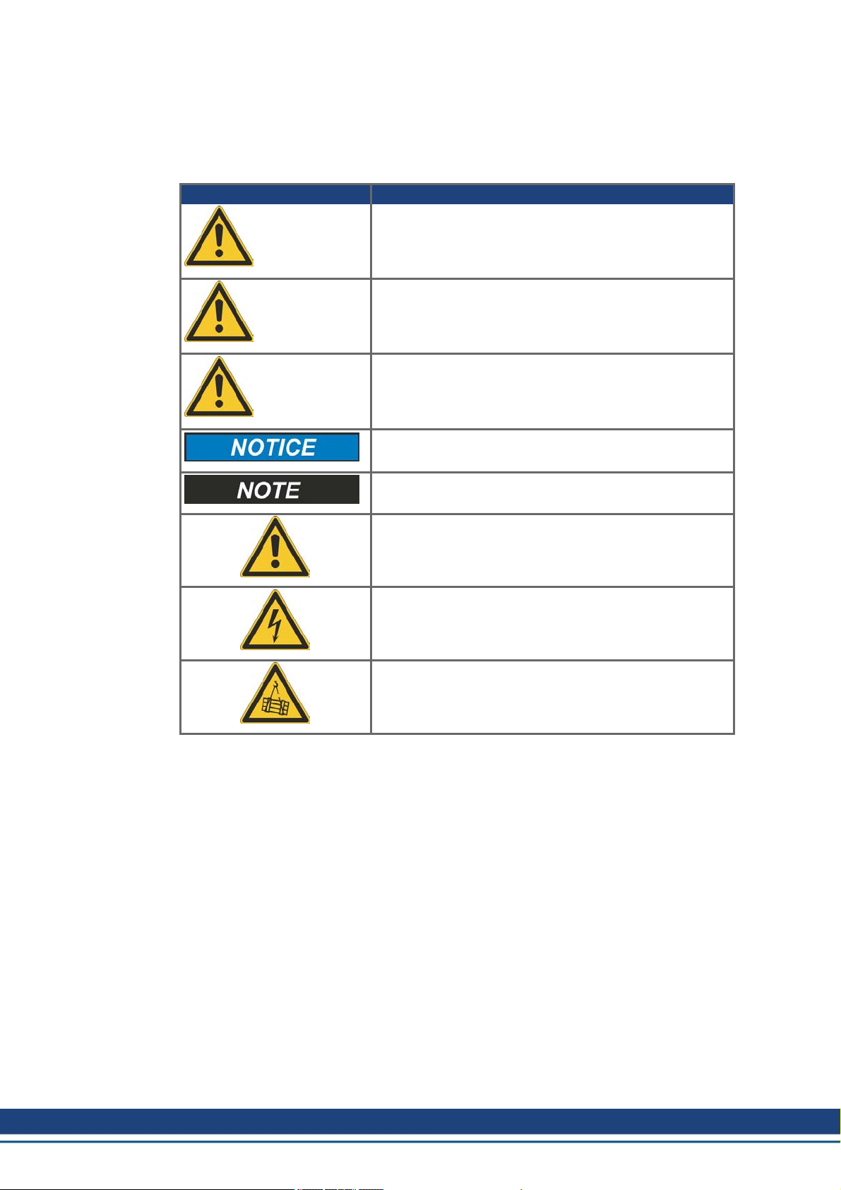
2.3.1 Symbols Used
Symbol Indication
Indicates a hazardous situation which, if not avoided, will
result in death or serious injury.
DANGER
Indicates a hazardous situation which, if not avoided, could
result in death or serious injury.
WARNING
Indicates a hazardous situation which, if not avoided, could
result in minor or moderate injury.
CAUTION
Indicates situations which, if not avoided, could result in
property damage.
This symbol indicates important notes.
Warning of a danger(general). The type of danger is specified by the text next to the symbol.
Warning of dangerfrom electricity and its effects.
Warning of suspended loads.
8 Kollmorgen | December 2014
Page 9
2.3.2 You should pay attention to this
Read the documentation!
Read the available documentation before installation and commissioning. Improper handling
of the devices can cause harm to people or damage to property. The operator must therefore
ensure that all persons entrusted to work on the devices have read and understood the
manual and that the safety notices in this manual are observed.
Always observe the whole drive system built with servo amplifier, cables, motor, accessories (filters, chokes, etc.). This means, that all documentation which exist for the components, must be available, must be read and must be understood.
Pay attention to the technical data!
Adhere to the technical data and the specifications on connection conditions (ratingplate and
documentation). If permissible voltage values or current values are exceeded, the devices
can be damaged, e.g. through overheating.
Specialist staff required!
Only properly qualifiedpersonnel are permitted to perform such tasks as transport,
assembly, setup and maintenance. Qualified specialist staff are persons who are familiar
with the transport, installation, assembly, commissioning and operation of power electronics
andwho bringtheir relevant minimum qualifications to bear on their duties. The qualified personnel must know and observe IEC 60364 / IEC 60664 and national accident prevention regulations.
Additional requirements on specialist staff may also result from the risk assessment.
Hot surface!
Some devices can reach temperatures of up to 250°C during operation. Touching them can
result in burns. Observe the permissible mounting position and ensure that a sufficient distance is maintained from neighboring assemblies.
Accessories Europe | 2 General
Earthing!
It is vital that you ensure that the device housing is safely earthed to the PE (protective
earth) busbar in the switch cabinet. Without low-resistance earthing no personal protection
can be guaranteed and there is a risk of death from electric shock.
High voltages!
Keep the switching cabinet closed when the equipment is in operation. Not having optical displays does not guarantee an absence of voltage. Power connections may carry voltage even
if the motor is not turning.
Do not unplug any connectors during operation. There is a risk of death or severe injury from
touching exposed contacts. Power connections may be live even when the motor is not rotating. This can cause flashovers with resultinginjuries to persons and damage to the contacts.
DC Bus link connections can carry dangerous voltage levels over an hour after the line
voltage has been switched off (self-discharge time). Danger of death from electric shock.
Beforecommencing work on the modules’ power terminals, check the voltage at the connection terminals is de-energized to ground and to each other.
.
Kollmorgen | December 2014 9
Page 10
Accessories Europe | 3 Digital Drive Systems
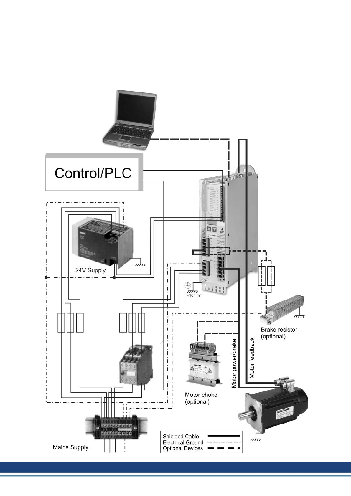
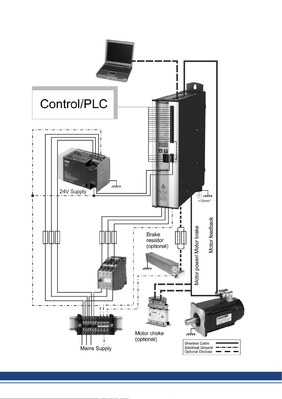
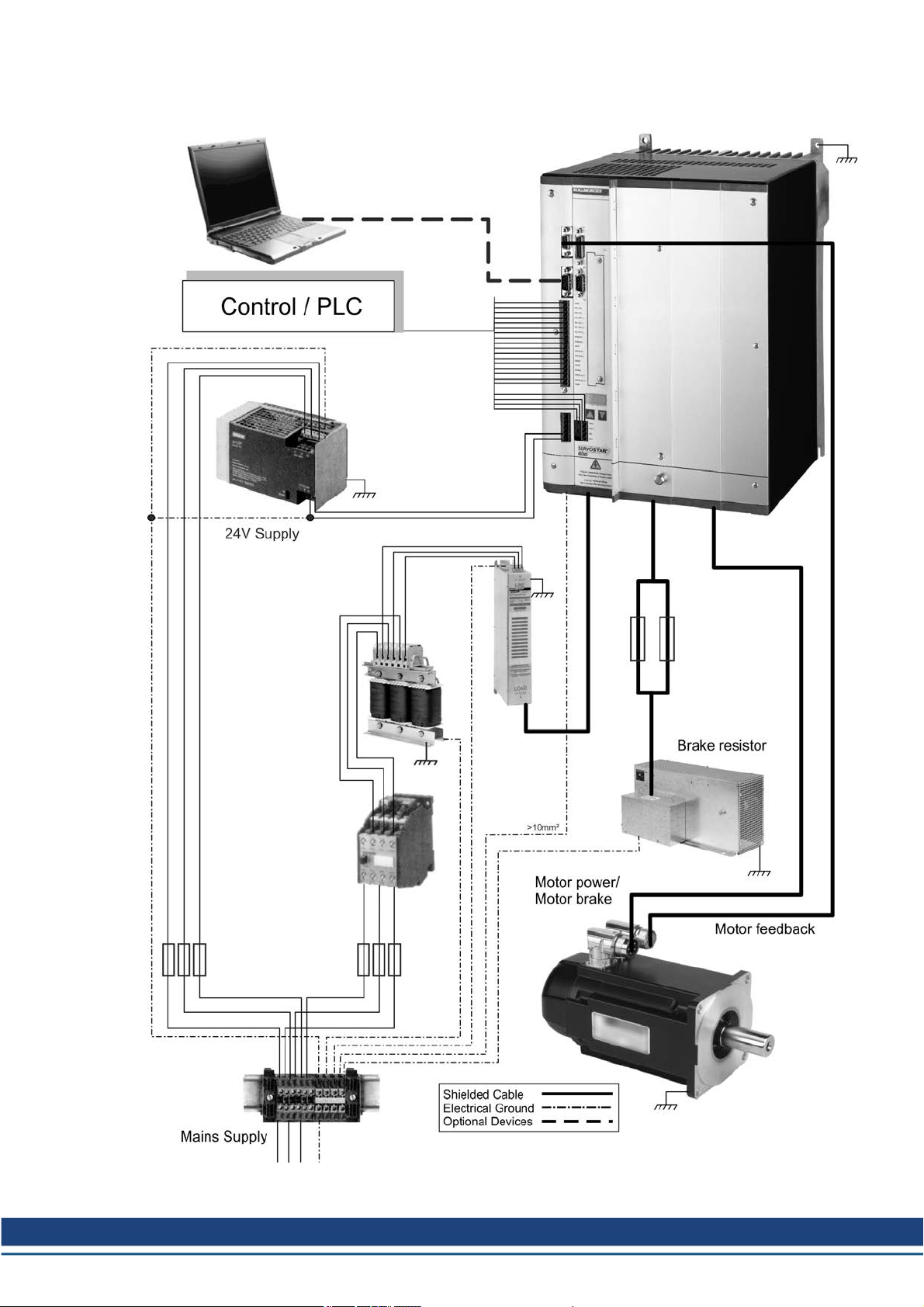
3 Digital Drive Systems
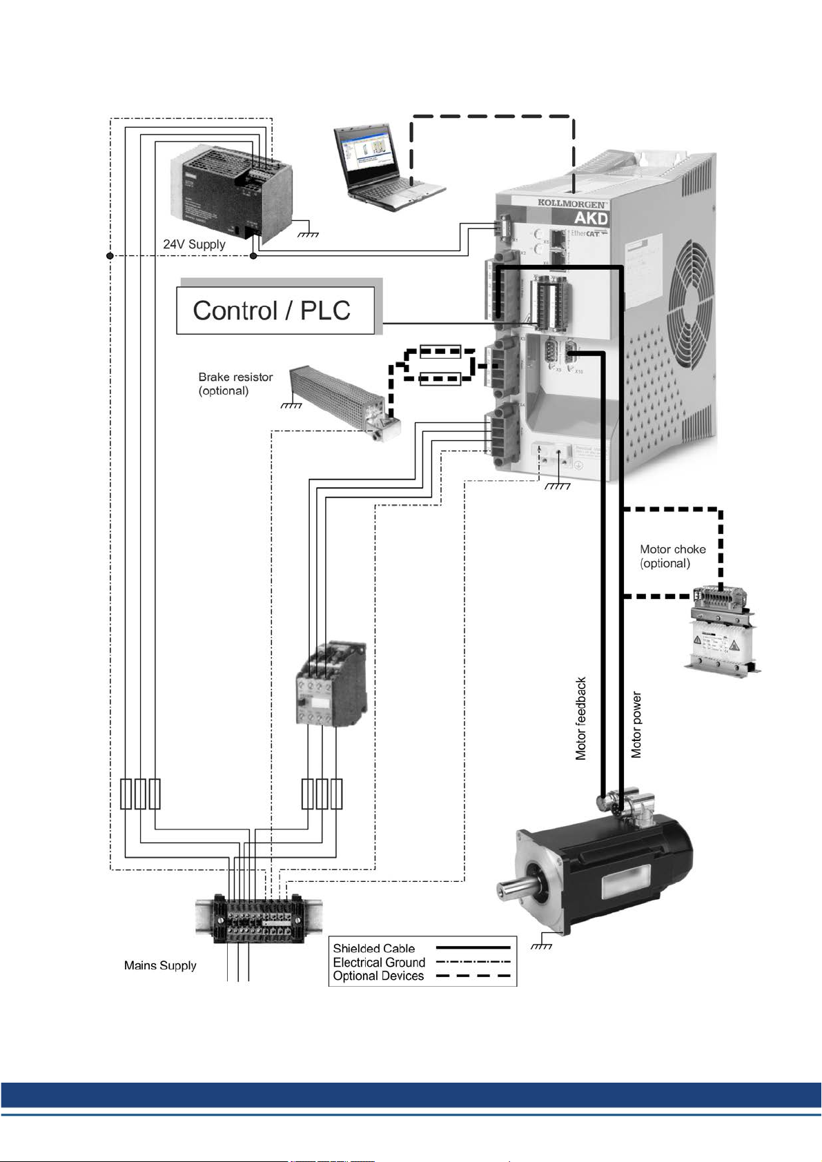
The systems shown are simply a possible scenario for setting up a digital drive system with
relevant servo amplifier components.
3.1 Drive System with S300
10 Kollmorgen | December 2014
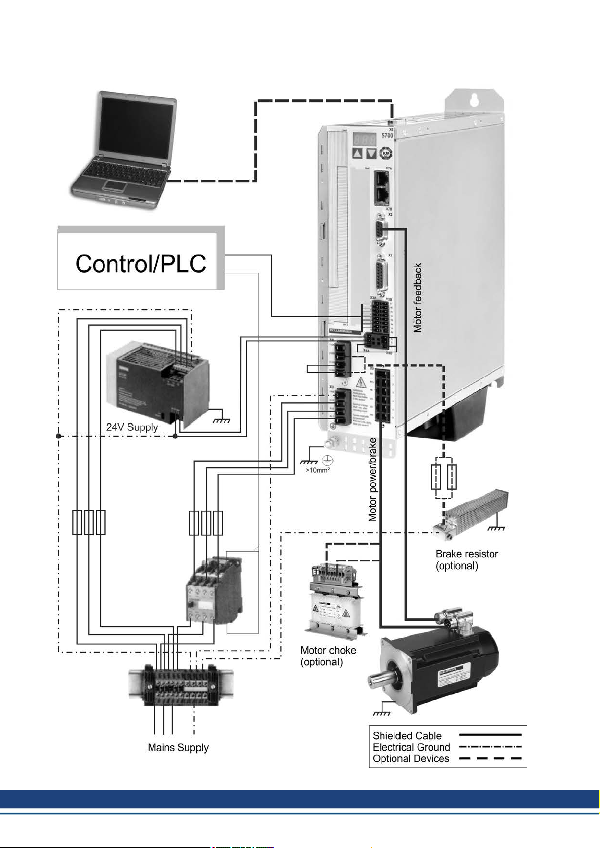
Page 11
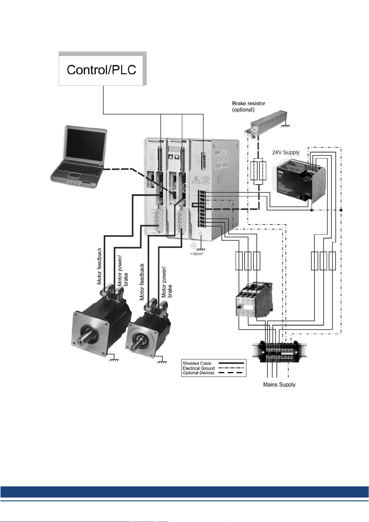
3.2 Drive System with S400
Accessories Europe | 3 Digital Drive Systems
Kollmorgen | December 2014 11
Page 12
Accessories Europe | 3 Digital Drive Systems
3.3 Drive System with S601...620
12 Kollmorgen | December 2014
Page 13
3.4 Drive System with S640...670
Accessories Europe | 3 Digital Drive Systems
Kollmorgen | December 2014 13
Page 14
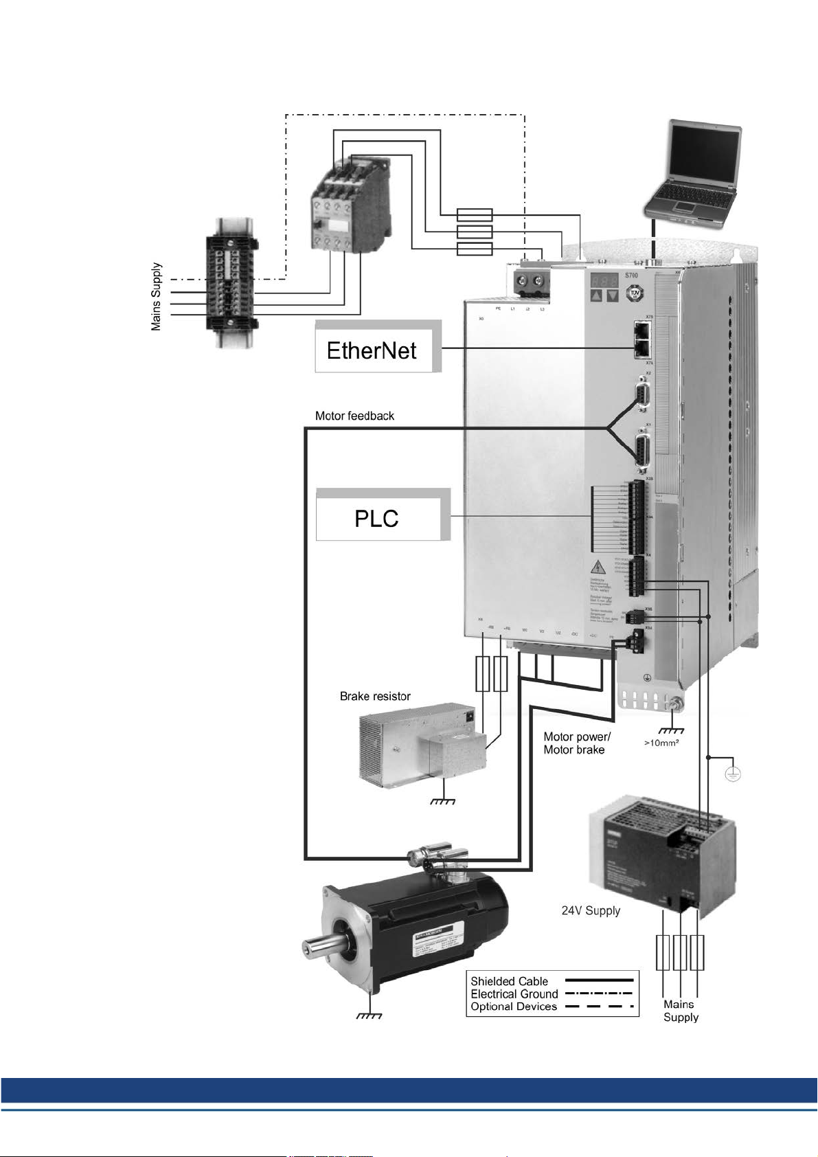
Accessories Europe | 3 Digital Drive Systems
3.5 Drive System with S701...724
14 Kollmorgen | December 2014
Page 15
3.6 Drive System with S748/772
Accessories Europe | 3 Digital Drive Systems
Kollmorgen | December 2014 15
Page 16
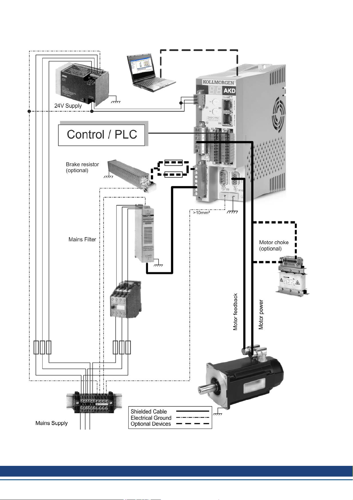
Accessories Europe | 3 Digital Drive Systems
3.7 Drive System with AKD-x00306...02406
16 Kollmorgen | December 2014
Page 17
3.8 Drive System with AKD-x00307...02407
Accessories Europe | 3 Digital Drive Systems
Kollmorgen | December 2014 17
Page 18

Accessories Europe | 3 Digital Drive Systems
3.9 Drive System with AKD-x04807
18 Kollmorgen | December 2014
Page 19
Accessories Europe | 3 Digital Drive Systems
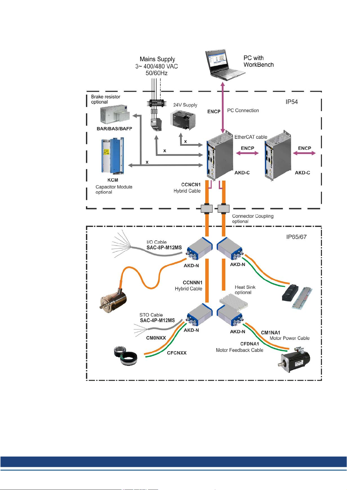
3.10 Decentralized Drive System with AKD-C and AKD-N
All components inside the borders aresuppliedby Kollmorgen with the exception of cables
signedwith "x". These cables are not suppliedby Kollmorgen, you should use cables or
wires according to EN 60204.
Kollmorgen | December 2014 19
Page 20
Accessories Europe | 4 Mechanical Accessories
4 Mechanical Accessories
4.1 Mounting Kit for AKMH Motors
IEC mounting kits with 1 shaft center screw and 4 flangescrews. Hygienic mounting is possible only with these screws.
Description Order Code
Mounting Hardware AKMH2, Ax flange / Cx front mounting MTG-KIT-AKMH2-IEC
Mounting Hardware AKMH3, Ax flange / Cx front mounting MTG-KIT-AKMH3-IEC
Mounting Hardware AKMH4, Ax flange / Cx front mounting MTG-KIT-AKMH4-IEC
Mounting Hardware AKMH5, Ax flange / Cx front mounting MTG-KIT-AKMH5-IEC
Mounting Hardware AKMH6, Ax flange / Cx front mounting MTG-KIT-AKMH6-IEC
NEMA mounting kits are described in the US selection guide, available from the Kollmorgen
website www.kollmorgen.com).
4.2 Suspension Unit for AKM motors
DANGER
Suspended load. Risk of death if load falls. Never step under the load,
while the motor is raised!
You must read the instructions manual for the suspension unit ZPMZ 120/292. Observe the
"safety instructions" and "use as directed" hints before starting transportation work.
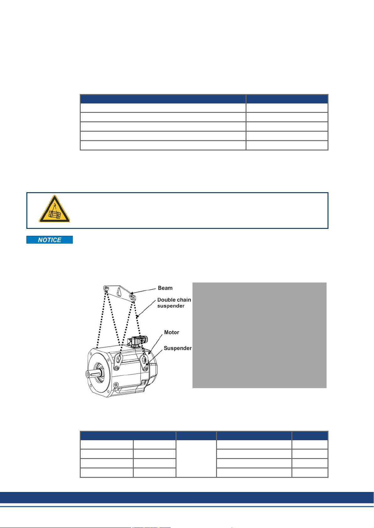
The Suspension Unit ZPMZ 120/292 is designed for suspended handlingexclusively of
motors (i.e., without attached units such as gearboxes, clutches, etc.) with a maximum
weight of 120 kg and maximum nominal span of the extreme suspension hooks of 292 mm.
The suspended unit consists of a Beam, suspended off the crane hook and two double-run
chain suspenders. The motormay be borne on two or four runs of thechain suspender.
The suspenders (number depends on the motor type) are delivered with the motor.
Technical Data
Lifting capacity 120kg Weight 0,83 kg
Nominal span 292 mm Number of cycles a year 20.000
Lugwidth 44,7 mm Average load 60 %
Lugheight 51 mm Order code FA00092
20 Kollmorgen | December 2014
Page 21

4.3 Fan Kit for AKM7 motors
Observe the mounting instructions delivered with the fankit. The fan housing can be mounted either with both the supplied brackets andspacers or with the brackets only. The choice
of mounting method depends on the application. If strong vibrations are expected, you should
use both brackets and spacers. Motors with integrated brakes require the longs spacers.
Mounting the fan kit enlarges the motor by approximately 65 mm. The detailed final dimensions of AKM7 motors with mounted fan kit can be found in the instructions manual of the
AKM motor series. Ventilation of AKM7 motors allow increased current of the motors. This
higher current usually requires larger wiring cross section compared to not ventilated motors.
The necessary data for current and wiring cross section can be found in the technical data
section of the AKM instructions manual.
Technical Data
Supply voltage 24 VDC
Supply current 270mA
Electrical power 6.5 W
Surface Coated with polyester powder coating in matt black, not resistant
Protection class IP 20
Connection Cable gland 10 mm, cable diameter 4 mm to 6 mm, recommended cable
Terminals 0.33 mm² to 4 mm²
Weight 2.52 kg
Order code AKM7-FAN
Accessories Europe | 4 Mechanical Accessories
against solvents
3x0.75 mm² (not part of delivery)
Kollmorgen | December 2014 21
Page 22
Accessories Europe | 4 Mechanical Accessories
4.4 Mechanical accessories for AKD-N and AKD-C
You must read the AKD-N/AKD-C installation manuals. Observe the safety instructions
given there before commencing mounting/installation work.
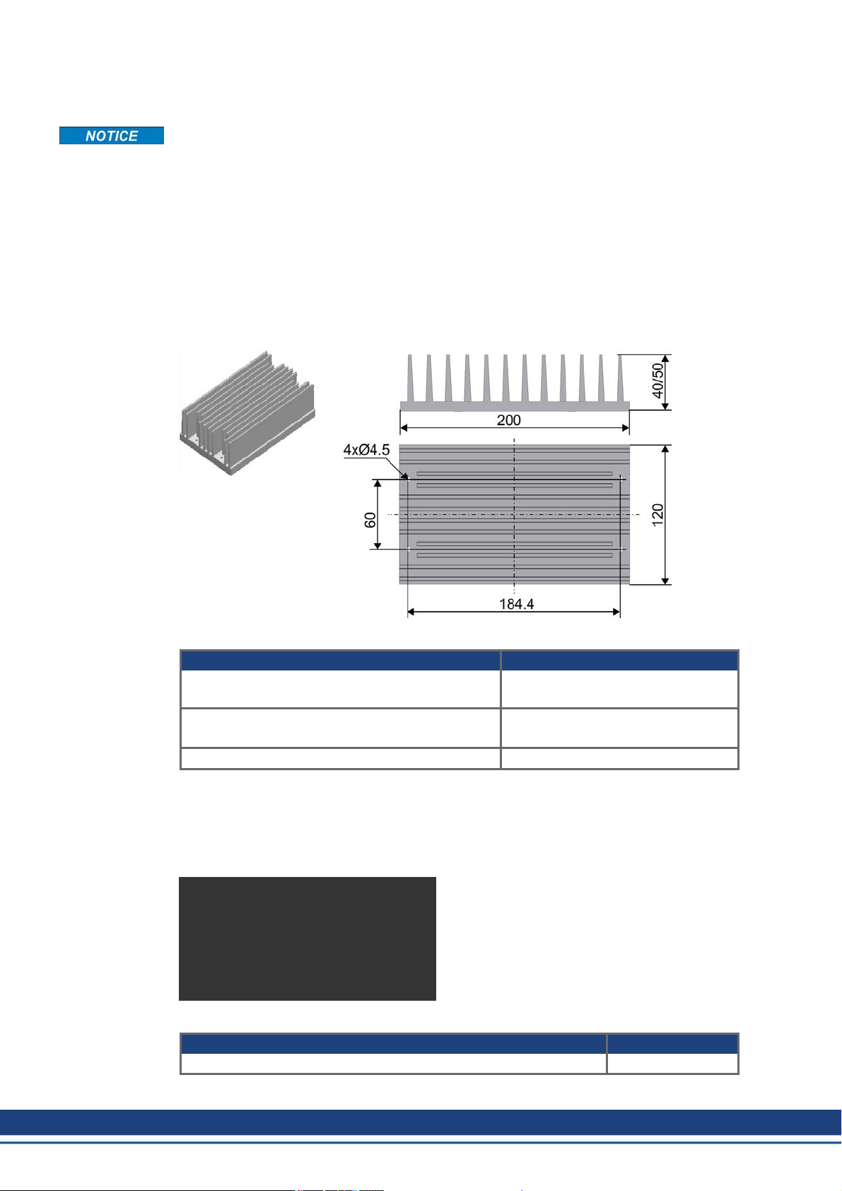
4.4.1 Heat Sink for AKD-N
When mounting AKD-N to themachinery, temperature management is important to ensure
maximum performance of the drive system. In case of medium or bad cooling situation (as
described in the AKD-N Installation Manual), youcan mount a heat sink to the AKD-N.
Heat flow is optimized by a heat conducting film, which must be placed between heat sink
andAKD-N.
Mounting holes in the heat sink and winding holes in the AKD-N are prepared for M4x16
hexagon socket screws to ISO 4762. Use a 3 mm T-handle Allen key for mounting.
Order Codes
Article Order codes
Heat sink Kit 40 mm with Heat conducting film and
4 screws M4x16
Heat sink Kit 50 mm with Heat conducting film and
4 screws M4x16
Heat conducting film 849-373000-04
4.4.2 Mounting clamps for AKD-N
The AKD-N servo amplifier is mounted to the machine with special mounting clamps. The
delivery package contains 4 clamps. In case of lost or damaged clamps, you can ordera set
of four clamps.
Order Codes
Article Order codes
AKD-N Mounting Clamps Set, 4 clamps AKD-N-M/C-Set
AKD-N 3,6 HEATSINK KIT 40MM
AKD-N 3,6 HEATSINK KIT 50MM
22 Kollmorgen | December 2014
Page 23
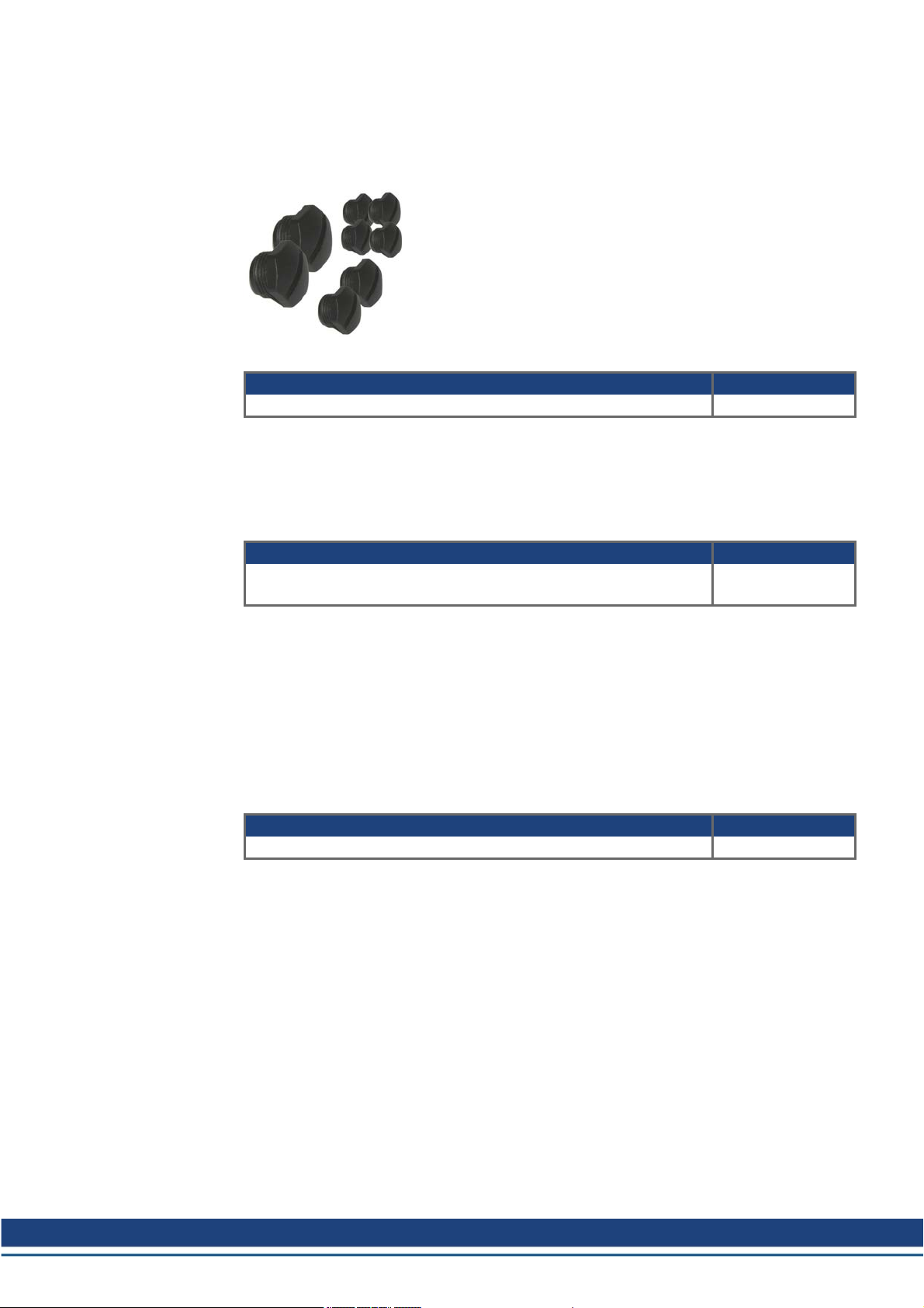
4.4.3 Sealing plugs for AKD-N connectors
The sealing plugs in the delivery package are screwed to unused AKD-N connectors to
ensure the IP class for the machine environment. In case of lost plugs, you can order a set
with 3 different plug sizes.
Order Code
Article Order Codes
AKD-N Sealing Plug Set, 4xM12, 2xM23, 2xM17 AKD-N-S/P-Set
4.4.4 Connector Kit for AKD-C
Mating connectors X12, X13, X14, X15, and X17 are part of delivery. If a mating connector is
lost or damaged, you can order the AKD-C Connector Kit.
Order Code
Accessories Europe | 4 Mechanical Accessories
Article Order Codes
AKD-N Connector Kit, included matingconnectors X12, X13, X14,
X15, and X17
4.4.5 Cabinet connector coupling for AKD-C/N
The connector couplingmust be built into the outer wall of a cabinet. The connector coupling
connects powerand signal lines as well as shielding of the hybrid cables and ensures the
long-term sealed transition between cabinet environment (IP54) and machine environment
(IP65/67).
Inside the cabinet the CCNCN1 cable (➜ p. 65) to AKD-C can be plugged in, outside the
cabinet the CCNNN1 cable (➜ p. 65) to AKD-N can be plugged in.
Order Codes
Article Order Codes
Hybrid Connector Coupling AKD-C/AKD-N AKD-CN-Coupling*
*in process
AKD-C-CONKIT
Kollmorgen | December 2014 23
Page 24
Accessories Europe | 5 Shield clamps
5 Shield clamps
You must read the instructions manuals for the servo amplifier/servo motor you areusing in
your application. Observe the safety instructions they contain before commencing mounting/installation work.
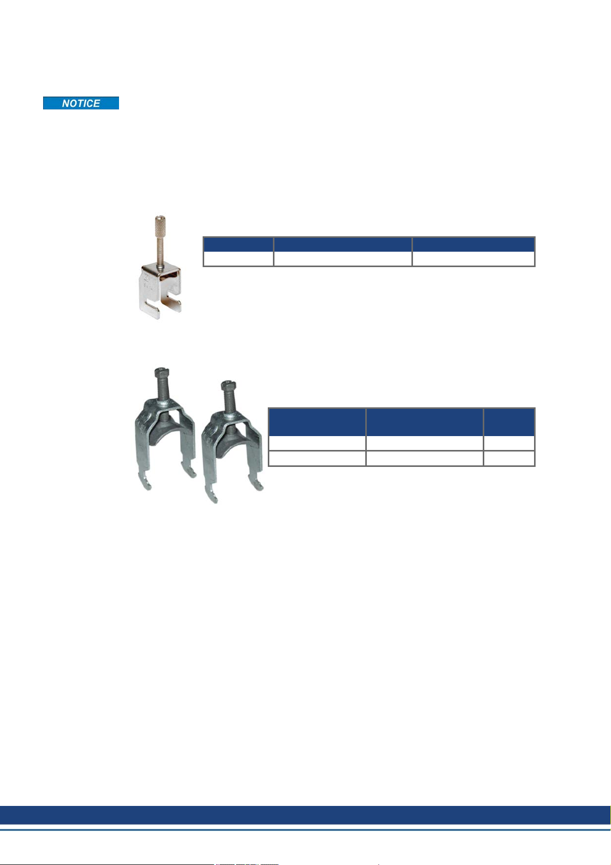
5.1 Auxiliary terminals on the servo amplifier
S300, S701...724 and AKD
These servo amplifiers feature slots on the front panel for the connection of
additional shield clamps.
Article Tension range Order Codes
SK14 6-13mm DE-108248
S640/670, S748/772
The shroud supplied with these servo amplifiers features
slots for the connection of additional shield clamps.
We recommend using the following shield clamp:
Manufacturer Article Tension
range
OBO (Bettermann) BBS-Schelle Typ 2056 16-22mm
OBO (Bettermann) BBS-Schelle Typ 2056 28-34mm
The clamps are part of delivery of the servo amplifier.
24 Kollmorgen | December 2014
Page 25
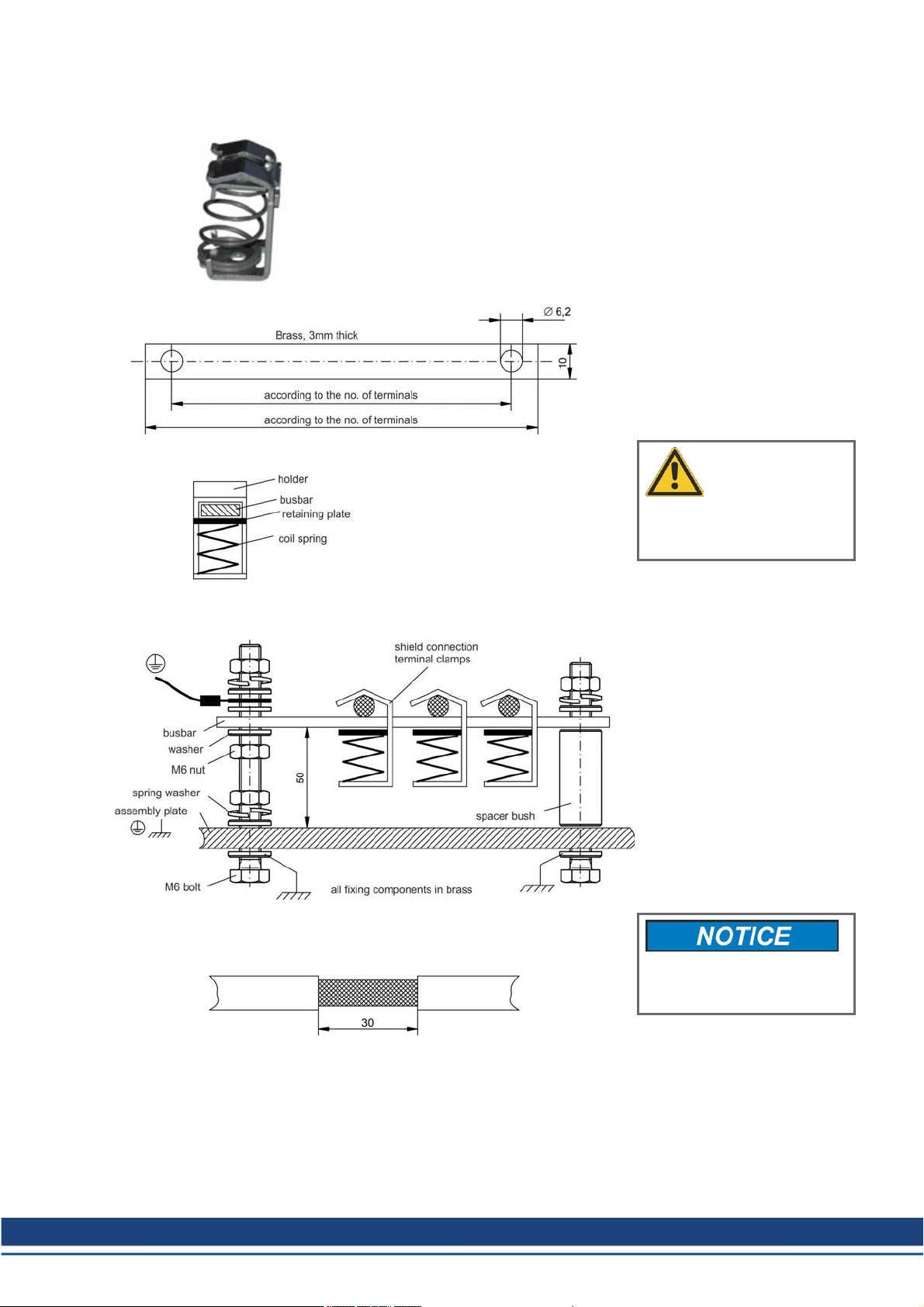
5.2 External shielding busbar
Accessories Europe | 5 Shield clamps
The power cable shields (line in, motor cable, external regen resistor)
can be routed to an additional busbar via shield clamps.
Kollmorgen recommends using Weidmüller KLBÜ shield clamps.
A possible scenario for setting up a busbar for the above shield
clamps is described below.
1. Cut a busbar of the required
length from a brass rail (cross-section 10 x 3 mm) and drill holes in it
as indicated. All shield clamps
required must fit between the drill
holes.
CAUTION
Risk of injury due to the spring
force of the coil spring. Use pincers.
2. Squeeze together the coil
spring and the supporting plate
and push the busbar through the
opening in the holder.
3. Mount the busbar with the
shield clamps fitted on the
assembly plate. Use either metal
spacer bushes or screws with nuts
and accessories to maintain a spacing of 50 mm. Earth the busbar
using a single conductor with a
cross-section of at least 2.5mm².
4. Strip the external cable sheath
to a length of approximately 30
mm, taking care not to damage
the braided shield. Push the
shield clamp up and route the
cable to it via the busbar.
Make sure there is good contact between the shield clamp
and the braided shield.
Kollmorgen | December 2014 25
Page 26
Accessories Europe | 6 Mains chokes
6 Mains chokes
You must read the instructions manuals for the servo amplifier and servo motoryou are using
in your application. Observe the safety instructions given there.
6.1 General
A 3L mains choke must be used on S640/670 servo amplifiers in order to reduce mains harmonics.
In special cases, if mains voltage is more than3% asymmetrical, then the S748/772 must be
used with a mains choke. In unfavorable combination of mains impedance and DC bus capacitance the unloaded DC bus may reach voltage up to 800V without choke. For EMC reasons
the chokes should be mounted isolatedto the cabinet. Single conductors can be used for wiring, shielded cables are not required. More information seeWIKI "Mains Choke".
Purpose of mains choke:
l Prevents impermissible loading of semiconductors in the event of rapid current rise during
commutation.
l Prevents voltage dips in the mains voltage causedby commutation.
l Reduces current ripple in the DC link, thereby increasing the service life of the DC link
capacitors.
6.2 Important notes
DANGER
Power terminals are capable of conducting hazardous voltage up to
10minutes after the mains voltage has been disconnected. Risk of electric shock. Before starting work on power terminals, check that the phaseto-earth and phase-to-phase voltages have de-energised.
Due to the high earth leakage currents induced by the system, you should observe the
requirements of EN 61800-5-1 (e.g. fixed installation, ≥ 10 mm² or double protective earth)
when carrying out mounting and installationwork. You must read the instructions manual for
the servo amplifier/servo motor you are using in your application and observe the safety
instructions they contain before commencing mounting/installation work.
Mounting: 50mm free space required above and below the device.
Connection diagram: see servo amplifier instructions manual.
6.3 Type assignment and order codes
Servo amplifier Mains choke
S640/670 (with asymmetrical mains >3% only) 4% uk
S748/772 (with asymmetrical mains >3% only) 2% uk
AKD, S300, S400, S601...620, S701...724 not required
Order Codes
Article uk Order codes
Mains choke 3L0,5-63-4 (0.47mH, 63A) 4% DE-92201
Mains choke 3L0,4-80-4 (0.37mH, 80A) 4% DE-92100
Mains choke 3L0,2-160-4 (0.19mH, 160A) 4% DE-92099
Mains choke 3L0,24-50-2 (0.24mH, 50A) 2% DE-201476
Mains choke 3L0,2-75-2 (0.20mH, 75A) 2% DE-201477
26 Kollmorgen | December 2014
Page 27

6.4 Mains choke 3L
A number of servo amplifiers can be connected to one and the same mains choke; the rated
current of the mains choke must be greater than or at least equal to the total current of the
connected servo amplifiers.
Accessories Europe | 6 Mains chokes
Photo: 3L0,2-160-4, all models
are similar
Technical Data
Inducti-
Type [mH] [A] [%] [mm] [mm] [mm] [mm] [mm] [mm] [mm²] [kg]
3L 0,5-63-4 0.47 63 4 185 170 77 122 215 8x12 16 9.65
3L 0,4-80-4 0.37 80 4 210 175 85 125 240 8x12 16 12.5
3L 0,2-160-4 0.19 160 4 291 273 116.5 148.5 310 10x18 95 27
3L 0,24-50-2 0.24 50 2 152.5 114.3 88.9 114.3 163 6.5 10 5.9
3L 0,2-75-2 0.20 75 2 185 170 77 122 220 8x12 35 9.9
vity
Nominal
Current
uk A B C D E F Termi-
nals
Weight
Kollmorgen | December 2014 27
Page 28

Accessories Europe | 7 Mains filters
7 Mains filters
7.1 General
AKD-x00306 to AKD-x02406 and S640/670 servo amplifiers require an external mains filter.
All other servo amplifiers feature built-in mains filters (see the relevant instructions manual).
The filtering effect of the mains filters can only be assured if the permissible throughput rating
of the mains filters is not exceeded even on peak loading of the servo amplifiers with Ipeak.
The max. available throughput rating of the mains filter must be higher than themax. power
consumption of the servo amplifiers and higherthan the maximum power consumption of the
motors. More information can be found on the WIKI page "Mains Filter".
7.2 Important notes
DANGER
Power terminals are capable of conducting hazardous voltage up to 10
minutes after the mains voltage has been disconnected. Risk of electric
shock. Before starting work on power terminals, check that the phase-toearth and phase-to-phase voltages have de-energized.
Due to the high earth leakage currents induced by the system, you should observe the
requirements of EN 61800-5-1 (e.g. fixed installation, ≥10 mm² or double protective earth)
when carrying out mounting and installationwork. You must read the instructions manuals for
the used components and observe the safety instructions they contain before commencing
mounting/installation work.See servo amplifier instructions manual for connection diagrams.
7.3 Type assignment and order codes
Servo amplifier Mains filter
S300, S400, S601...620, S700, AKD-x00307...04807 (240 to 480V) not required
S640/670 3EF
AKD-B/P/T/M 00306...02406 (120 to 240V) 1NF, 3NF
Article Order code Remarks
Mains filter 1NF-10 (230 VAC, 10A) DE-201565 1~, 230V AC, CE*, UL
Mains filter 1NF-12 (230 VAC, 12A) DE-201566 1~, 230V AC, CE*, UL
Mains filter 1NF-20B (125V/230 VAC, 20A) DE-201865 1~, IEC 230V AC, UL 125 V AC, CE*
Mains filter 1NF-25 (230 VAC, 25A) DE-201568 1~, 230V AC, CE*, UL
Mains filter 3NF-07 (480 VAC, 07A) DE-201569 3~, 480V AC, CE*, UL
Mains filter 3NF-16 (480 VAC, 16A) DE-201570 3~, 480V AC, CE*, UL
Mains filter 3NF-30 (480 VAC, 30A) DE-201571 3~, 480V AC, CE*, UL
Mains filter 3EF-42 (480 VAC, 42A) DE-92102 3~, 480V AC, CE*, UL
Mains filter 3EF-75 (480 VAC, 42A) DE-92103 3~, 480V AC, CE*, UL
Mains filter 3EF-100 (480 VAC, 42A) DE-92104 3~, 480V AC, CE*, UL
Mains filter 3EF-130 (480 VAC, 42A) DE-92105 3~, 480V AC, CE*, UL
* No EC directive matches mains filters actually. You can use the filters in Europe, they are manufactured according to harmonized standards concerning creeping and voltage distances.
28 Kollmorgen | December 2014
Page 29

7.4 Mains filters 1NF-10...12
Accessories Europe | 7 Mains filters
Observe the safety instructions ➜ p. 28.
For single-phase operation only.
Technical Data
Nominal
Type
1NF-10 10 230 85 49 40.3 54 75 5.3 6.3 87 0.29 Fast-on
1NF-12 12 230 156 57.5 45.4 130.5 143 5.3 6 156 0.73 Fast-on
* at 40°C environment temperature
Current
[A]*
Nominal
Voltage
[V]
A
[mm]B[mm]C[mm]D[mm]F[mm]M[mm]N[mm]P[mm]
Kollmorgen | December 2014 29
Weight
[kg]
Connec-
tion
Page 30

Accessories Europe | 7 Mains filters
7.5 Mains filters 1NF-20B, 1NF-25
Observe the safety instructions ➜ p. 28.
For single-phase operation only.
Technical Data
Type Nominal
Current [A]*
1NF-20B 20 230V 125V 0.93
1NF-25 25 230V 230V 0.7
* at 50°C environment temperature
30 Kollmorgen | December 2014
Nominal Voltage
IEC UL/CSA Weight
[kg]
Connection Phase
Terminals
Wires up to 4mm²
Torque 0.6 to 0.8 Nm
Wires up to 10mm²
Torque 1.5 to1.8 Nm
Connection PE
Bolt M 6
Torque 3.5 to 4 Nm
Page 31

7.6 Mains filters 3NF-07...30
Accessories Europe | 7 Mains filters
Observe the safety instructions ➜ p. 28.
Technical Data
Type Nom.
Current*A[mm]B[mm]C[mm]D[mm]F[mm]G[mm]M[mm]P[mm]
3NF-07 7 A 190 40 70 160 180 20 4.5 180 0.5 4mm²,
3NF-16 16 A 250 45 70 220 235 25 5.4 240 0.8
3NF-30 30 A 270 50 85 240 255 30 5.4 260 1.2
* at 50°C environment temperature
Kollmorgen | December 2014 31
Weight
[kg]
Terminals PE
0.7..0.8Nm
10mm²,
1.9..2.2Nm
Bolt
M5,
2.2Nm
Page 32

Accessories Europe | 7 Mains filters
7.7 Mains filters 3EF-42...130
Observe the safety instructions ➜ p. 28.
Technical Data
Type Nom.
Current*L1[mm]L2[mm]L3[mm]L4[mm]B1[mm]B2[mm]B3[mm]H1[mm]
3EF-42 42 A 305 335 320 355 35 60 7 150 10 5
3EF-72 75 A 300 330 314 380 55 80 7 185 25 6
3EF-100 100 A 300 330 314 380 55 80 7 220 25 8
3EF-130 130 A 350 380 364 440 65 90 7 220 50 10
32 Kollmorgen | December 2014
Terminals
[mm²]PEBolt
[mm]
Page 33

8 Brake resistors
8.1 General
Duringbraking with the aid of the motor, energy is fed back into the servo amplifier. This
regenerative energy is dissipated as heat in the brake resistor. The brake resistor is switched
on by the brake circuit. Different resistance values have to be used depending on the servo
amplifier. All resistors meet the requirements of CE directives and are UL-registered.
Hints for calculation of the brake power can be found in our Product WIKI on page "Cal-
culation of brake power", more information to the resistors are given on WIKI page "Brake
Resistors".
8.2 Important notes
WARNING
The brake resistor surface temperature can exceed 250°C. Risk of burns!
Measure the temperature and wait until temperature dropped down below
40°C, before touching the resistor housing.
Accessories Europe | 8 Brake resistors
Inadequate levels of cooling air or incorrect installation can lead to overheating and destruction of the resistor and surrounding components.
l May only be installed in switchgear cabinets, comply with the permissible installation
types and clearances (see dimensional drawing).
l Ensure there is unobstructed convection for cooling purposes.
l Use temperature-resistant materials in the vicinity of the resistor.
l The connection terminals must never be located within the flow range of the heated waste
air.
The following requirements must be met to ensure the brake resistors work properly:
l Compliance with required installation clearances
l Compliance with permissible installation type
l Unhindered access of cooling air
l Unhindered diverting of warmed up air
l Rated data with maximum ambient temperature 40°C, in case of ambient temperature
higher than 40°C, power must be reduced by 4% per 10K temperature rise
You must read the instructions manual for the servo amplifier/servo motor youare using in
your application and observe the safety instructions they contain before commencing mounting/installation work.
A connection diagram appears in the servo amplifier's instructions manual.
Kollmorgen | December 2014 33
Page 34

Accessories Europe | 8 Brake resistors
8.3 Type assignment and order codes
Servo amplifier Brake resistor
S300 (S3xx61) BAR(U) 66 optional
S300 (S3xx01) BAR(U) 91 optional
S400, S601...620, S701-712 BAR(U) 33 optional
S640, S748 BAS(U) 15 usually required
S670, S772 BAS(U) 10 usually required
S724 BAR(U)/BAS(U) 23 optional
AKD-x00306* BAFP(U)/BAR(U)/BAS(U) 33 usually required
AKD-x00606* BAFP(U)/BAR(U)/BAS(U) 33 usually required
AKD-x01206* BAR(U)/BAS(U) 15 optional
AKD-x02406* BAR(U)/BAS(U) 15 optional
AKD-x00307* BAR(U)/BAS(U) 33 optional
AKD-x00607* BAR(U)/BAS(U) 33 optional
AKD-x01207* BAR(U)/BAS(U) 33 optional
AKD-x02407* BAR(U)/BAS(U) 23 optional
AKD-x04807* BAS(U) 10 optional
AKD-C01007 BAR(U)/BAS(U) 33 optional
Resistance/Ω
Remarks
Order codes
Article Amplifier Resis-
tance
Brake resistor BAS(U) 2000-10 S670,S772,
Brake resistor BAS(U) 3000-10 10 3000 4800 DE-103875
Brake resistor BAS(U) 6000-10 10 6000 9600 DE-103876
Brake resistor BAR(U) 500-15 AKD-x01206 & x02406,
Brake resistor BAR(U) 1000-15 15 1000 1600 DE-201440
Brake resistor BAS(U) 2000-15 15 2000 3200 DE-103871
Brake resistor BAS(U) 3000-15 15 3000 4800 DE-103872
Brake resistor BAS(U) 6000-15 15 6000 9600 DE-103873
Brake resistor BAR(U) 600-23 AKD-x02407, S724 23 600 960 DE-200613
Brake resistor BAR(U) 1000-23 23 1000 1600 DE-200614
Brake resistor BAS(U) 2000-23 23 2000 3200 DE-200615
Brake resistor BAS(U) 3000-23 23 3000 4800 DE-200616
Brake resistor BAS(U) 4000-23 23 4000 6400 DE-200617
Brake resistor BAFP(U) 100-33 AKD-x00306 to -x00606
Brake resistor BAFP(U) 200-33 33 200 320 DE-201438
Brake resistor BAR(U) 250-33 33 250 400 DE-106254
Brake resistor BAR(U) 500-33 33 500 800 DE-106255
Brake resistor BAR(U) 1500-33 33 1500 2400 DE-106258
Brake resistor BAS(U) 3000-33 33 3000 4800 DE-201407
Brake resistor BAR(U) 300-66 S300 (S3xx61) 66 300 480 DE-107161
Brake resistor BAR(U) 600-66 66 600 960 DE-107162
Brake resistor BAR(U) 1000-66 66 1000 1600 DE-107163
Brake resistor BAR(U) 300-91 S300 (S3xx01) 91 300 480 DE-107164
Brake resistor BAR(U) 600-91 91 600 960 DE-107165
Brake resistor BAR(U) 1000-91 91 1000 1600 DE-107166
*= AKD-x means AKD variants -B, -P, -T and -M
AKD-x04807
S640, S748
AKD-x00307 to -x01207,
AKD-C01007, S400,
S601...620, S701-712
Rated
Power
[Ω]
10 2000 3200 DE-103874
15 500 800 DE-201439
33 100 160 DE-201437
[W]
Max.
Power
[W]
Order code
34 Kollmorgen | December 2014
Page 35

8.4 External brake resistor BAFP(U)
Accessories Europe | 8 Brake resistors
Protection class: IP40
WARNING
The surface temperature can exceed 250°C.
Risk of burns and fire! Measure the temperature before touching.
Kollmorgen | December 2014 35
Page 36

Accessories Europe | 8 Brake resistors
8.5 External brake resistor BAR(U)
Protection class: IP20
WARNING
The surface temperature can exceed 250°C.
Risk of burns and fire! Measure the temperature
before touching.
36 Kollmorgen | December 2014
Page 37

8.6 External brake resistor BAS(U)
Accessories Europe | 8 Brake resistors
Protection class: IP20
WARNING
The surface temperature can exceed 250°C.
Risk of burns and fire! Measure the temperature
before touching.
Kollmorgen | December 2014 37
Page 38

Accessories Europe | 9 Capacitor Modules
9 Capacitor Modules
9.1 General
KCM modules (KOLLMORGEN Capacitor Modules) absorb energy generated by the motor
when it is operating in generator mode. Normally, this energy is dissipated as waste via
brake resistors. KCM modules, however, feed the energy they have stored back into the DC
Bus link as and when it is required.
KCM-S Saves energy: The energy stored in the capacitor module during generative brak-
ing is available the next time accelerationhappens. The module’s inception
voltage is calculated automatically during the first load cycles.
KCM-P Power in spite of power failure: If the power supply fails, the module provides the
servo amplifier with the stored energy that is required to bringthe drive to a standstill in a controlled manner (this only applies to the power supply voltage; batteryback the 24 V supply separately).
KCM-E Expansion module forboth applications. Expansion modules are available in two
capacitance classes.
9.2 Important notes
DANGER
DC Bus link terminals in servo systems carry high DC voltage of up to
900 V. Touching the terminals while they are carrying voltage is
extremely dangerous. Switch off (disconnect) the line voltage. You must
only work on the connections when the system is disconnected.
It can take over an hour for the modules to self-discharge. Check the state
of charge with a measuring device that is suitable for a DC voltage of up
to 1,000 V. When measuring a voltage of over 60 V between the
DC+/DC- terminals or to ground, discharge the modules as described in
the KCM Instructions Manual.
You must read the instructions manual for the servo amplifier/servomotor you are using in
your application and observe the safety instructions they contain before commencing mounting/installation work.
Wiring diagram and more important notes concerning wiring can be found in the KCM instructions manual and in the instructions manual of the used servo amplifier.
38 Kollmorgen | December 2014
Page 39

9.3 Type assignment and order codes
Servo amplifier KCM Module Servo amplifier KCM Module
S300 all Modules S640, S670 not allowed
S400 all Modules S748, S772 not allowed
S601 to S620 all Modules AKD-x00306...02406* not allowed
S701 to S724 all Modules AKD-x04807 not allowed
AKD-x00307...02407* all Modules AKD-C01007 all Modules
*= x means variants -B, -P, -T and -M
Order codes
Type/Order Code Remarks
KCM-S200-0000 Energy Saving Module, 1.6 kWs
KCM-P200-0000 Power Module, 2 kWs
KCM-E200-0000 Expansion Module 2 kWs
KCM-E400-0000 Expansion Module 4 kWs
Accessories Europe | 9 Capacitor Modules
9.4 Example installation with AKD-P, KCM-P and KCM-E
Maximum cable length between AKD and KCM: 500 mm. The DC+ and DC- lines should
always be twisted, maximum cross section is 6 mm².
RS422 interface X4 allows data exchange controlled by a terminal software of your choice.
Interface setting: 115200 Baud, 8 Data Bits, 1 Stop Bit, No Parity&Flow Control. The X4 mating connector is in the package. The ready signal reports the ready to operate (high level).
More information is given in the KCM Instructions Manual.
Kollmorgen | December 2014 39
Page 40

Accessories Europe | 9 Capacitor Modules
9.5 KCM Module
Observe the safety instructions ➜ p. 38 and in the instruction manual
of the servo amplifier.
Permissible assembly type: Vertical, ground connections at the bottom.
Otherassembly positions are not permitted. Observe the required free space
to next device. Ensure there is unobstructed convection for cooling purposes.
Technical Data
Storage
Type
KCM-S200 1600
KCM-P200 2000 470 VDC 6.9
KCM-E200 2000 - 4.1
KCM-E400 4000 - 6.2
40 Kollmorgen | December 2014
Capacity
[Ws]
Rated supply
voltage
[V=]
max 850 VDC
Peak supply
voltage
[V=]
max 950VDC
(30s in 6min)
Power
Protection
[kW]
18 IP20
Class
Inception
voltage
[V=]
calculated 6.9
Weight
[kg]
Page 41

10 Motor chokes
10.1 General
Shielded motor cables
For reasons of electromagnetic compatibility, the motor must be supplied with power via a
shielded cable. The structure of a cable with 100% shielding and the capacity equivalent circuit diagram (to earth) are shown below.
Why use motor chokes?
l To compensate high capacitive charge/dischargecurrents typical of shieldedmotor
cables approximately 25 m and longer.
l To reduce current alternation noise in the motor.
l To reduce current ripple in themotor.
Accessories Europe | 10 Motor chokes
The digital servo amplifiers’ high switchingfrequencies andsteep switchingedges give rise
to the transfer of capacitive currents to the shield by the three phases (U, V, W). These currents flow from the shield to earth. Dependingon the cable length and cable capacity (determined by design), this can lead to the generation of shield currents with peak values of up to
20A.
These shield currents place a loadon the servo amplifiers and motor and, on large systems,
lead to shifts in potential which can damage other components.
This effect is evident in particular on systems with multiple amplifiers operating in parallel on
the same mains filter.
The motor chokes slow down the rate of rise of the motor current (reduce edge steepness),
thereby reducing thecurrent transferred to the shield.
Why is the cross-section of the motor cable important?
Motor cables longer than 50 m with a small cross-section (e.g. 4 x 1.0 mm²) and therefore a
higher equivalent resistance are able to reduce the oscillation tendency of the LCR oscillating circuit (amplifier/choke/cable/motor). This cross-section can also be advantageous for
cable lengths shorter than 50 m if the cable capacity and motorinductance are very high.
However, the current loading of the cable must always be within thelimits specified by
EN60204.
Kollmorgen | December 2014 41
Page 42

Accessories Europe | 10 Motor chokes
10.2 Important notes
CAUTION
The choke can become hot during operation (rising to temperatures in
excess of 80° C). Risk of light burns and fire! Therefore, you should make
sure that the choke is mounted a sufficient distance away from neighbored components. Provide the requisite conditions for unobstructed convection to cool the choke.
You must read the instructions manual for the servo amplifier/servo motor youare using in
your application and observe the safety instructions they contain before commencing mounting/installation work. This manual is only valid in conjunction with the instructions manual for
the servo amplifier and servo motor you are using in your application.
Mount the motor choke 3YLN on a conductive earthed assembly plate in the switchgear cabinet. The choke box 3YL-24can be mounted to DIN rails as well.
The motor choke is wired into the cable close to the amplifier. When laying the motor cable,
allow about 400 mm for the connection to the choke.
Connection diagram see the servo amplifierinstructions manual.
10.3 Type assignment and order codes
Servo amplifier Motor choke Condition
S300 3YL-24, 3YLN-xx Motor cable ≥ 25m
S400 3YL-24, 3YLN-xx Motor cable ≥ 25m
S601...620 3YL-24, 3YLN-xx Motor cable ≥ 25m
S640/670 not required
S701...724 3YL-24, 3YLN-xx Motor cable ≥ 25m
S748/772 usually not required, in case of cable length ≥ 25m
AKD-x003 to AKD-x006* 3YLN-06 Motor cable ≥ 25m
AKD-x012* 3YLN-14 Motor cable ≥ 25m
AKD-x024* 3YLN-24 Motor cable ≥ 25m
*= x means variants -B, -P, -T and -M
Order codes
Article Nominal Current Approvals Order code
Motor choke box 3YL-24 24 A CE DE-90074
Motor choke 3YLN-06 6 A CE, UL DE-107929
Motor choke 3YLN-10 10 A CE, UL DE-107930
Motor choke 3YLN-14 14 A CE, UL DE-107931
Motor choke 3YLN-20 20 A CE, UL DE-107932
Motor choke 3YLN-24 24 A CE, UL DE-201447
andunusual conditions, ask our customer support
42 Kollmorgen | December 2014
Page 43

10.4 Motor choke 3YL-24
Accessories Europe | 10 Motor chokes
Technical data:
Rated data Sym Unit 3 YL-24
Rated Current I0rms A Max.3x 24
Frequency fmax kHz 8.3
Inductivity L µH 120
Resistance R mOhm 2.6
Weight G kg 1.4
Cable diameter (Shield clamp) - mm 4 to 13.5
Wire cross section U-V-W max. (terminals) - mm² 4
Wire cross section BR+/- max. (terminals) - mm² 2.5
Kollmorgen | December 2014 43
Page 44

Accessories Europe | 10 Motor chokes
10.5 Motor choke 3YLN-xx
Technical Data:
Rated Data Sym DIM 3YLN-06 3YLN-10 3YLN-14 3YLN-20 3YLN-24
Rated current I0rms A 6 10 14 20 24
Rated voltage Unom V 480
Rated frequency fnom Hz 0 to 150
Max. frequency fmax kHz 8
Inductivity L µH 900 900 900 450 450
Power loss P W 12 14.5 19.4 22.3 23.2
Protection class - - IP00
Temperature class - - F
Operation class - - S1
Weight G kg 4.5 5.5 10 10 10
Cable diameter
(Shield clamp)
Wiring cross section max.
(Terminals)
Width A mm 155 155 190 190 190
Depth B mm 90 105 125 125 125
Height C mm 195 195 230 230 230
Mounting hole distance D mm 130 130 170 170 170
Mounting hole distance E mm 56.5 71.5 78 78 78
Mounting screws F - 4xM6 4xM6 4xM6 4xM6 4xM6
- mm 4 to 13.5
- mm² 10 10 16 16 16
44 Kollmorgen | December 2014
Page 45

11 Cables
Kollmorgen assumes no liability for errors or damage to equipment caused by cables manufactured by customers.
11.1 Technical data for cables
Information on the chemical, mechanical and electrical characteristics of the cables can be
found in our Technical WIKI (Cables).
Insulation material
Sheathing: PUR (polyurethane, code 11Y)
Core insulation: PETP (polyesteraphthalate, code 12Y)
Capacitance (phase to shield)
Motor cable: less than 180 pF/m (cross sections >6mm² have larger capacitance)
Feedback cable: less than 120 pF/m
Hybrid Cable: special requirements
Accessories Europe | 11 Cables
11.2 Tools
Technical data
l The brackets in the core definition indicate the shielding
l All cables are suitable for use as trailing cables
l The technical data refer to use as moveable cables
l Operating life : 10 millionbending cycles
l All cables are UL recognized
Only work with the special tools that are required for the used connectors. You can obtain
these special tools from the manufacturer of the connectors or contacts.
Kollmorgen | December 2014 45
Page 46

Accessories Europe | 11 Cables
11.3 PC connection
11.3.1 AKD
The AKD is connected by a standards net cable with RJ45 connectors to the PC or to a
Switch/Hub.
Article Order Code
Ethernet Cable PC-AKD ➜ p. 59
11.3.2 S300, S400, S600, S700
Kollmorgen digital "Sx" type servo amplifiers are equipped with a serial RS232interface to
facilitate communication with a standardpersonal computer (PC). Various types of interface
can be used on the PC. Appropriate cables and in some cases specific accessories will be
required to establish the connection between servo amplifier and PC.
Article Order Code
Cable PC-S300/S400/S600/S700 3m, 9poles DE-90067
Setup Kit S300/S400/S600/S700 USB DE-107666
Y-Adapter for splitting CAN/RS232 and Multilink ➜ p. 47
Setup Kit S300, S400, S600, S700 USB
PC cable for S300, S400, S600, S700
An interface converter is required to use the USB
interface on a PC. Our "USB" setup kits contain a
USB serial converterand a serial PC cable suitable for the amplifier type.
For the purpose of parameterisation and for firmware upgrades, the servo amplifiers can be connected to the serial RS232 interface on a PC. The
connecting cable must be shielded. The braided
shield on the RS232 connecting cable is conductively connected to the front panel of the servo
amplifier via the connector housing on the Sub-D
male connector.
46 Kollmorgen | December 2014
Page 47

Accessories Europe | 11 Cables
Y Adapter (Splitter) for S300/S600/S700
The signals for the serial link to the PC and the CAN interface are routed via the same connector on the servo amplifier (X6). Our Y adapters can be used for simultaneous access to
both interfaces. In this case, the interface signals arerouted via separate connectors.
Article Order Code
Y-Programming-Adapter 1 Axis DE-108211
Y-Adapter -SR6Y- 4 Axes (Multilink Cable) DE-90060
Y-Adapter -SR6Y6- 6 Axes (Multilink Cable) DE-92042
The multi-axis Y adapters support the simultaneous setup (multi-link) of a number of
S300/S600/S700 in a single setupsession.
Y-adapter for 1 Axis Y-adapter for 4 axes Y-adapter for 6 axes
Kollmorgen | December 2014 47
Page 48

Accessories Europe | 11 Cables
11.4 Power Voltage Supply, external brake resistor, DC bus link
The connectors used (40 A andhigher fixed terminals) are included in the scope of supply of
the servo amplifier. If necessary, the connectors are coded and printed with the corresponding terminal designation. The table indicates the type of cable required for each intendedpurpose.
We do not deliver configured cables for this interface.
You must always observe the specifications in respect of cable cross-sections contained in
the instructions manual for the servo amplifieryou are using in your application. Fit suitable
wire endferrules or plug connectors to stripped conductors. A connection diagram appears in
the servo amplifier instructions manual.
11.4.1 Mating connector (part of delivery)
Mains supply 1 Mains supply 2 DC-link bus Brake resistor
Amplifier # Order Code # Order Code # Order Code # Order Code
S300-230V X0 DE-105856 - - X8 DE-107556 X8 DE-107556
S300-400V X0 DE-107557 - - X8 DE-107558 X8 DE-107558
S400 X0 DE-102583 - - X0 DE-102583 X0 DE-102583
S601...620 X0A DE-92258 X0B DE-92259 X7 DE-90064 X8 DE-90065
S701...724 X0 DE-200451 - - X8 DE-200452 X8 DE-200452
AKD-
x00306/00606*
AKD-x01206* X3 CON-
AKDx02406/0xx07*
AKD-C01007 X12 Connector Kit
X3 CON-
AKDX3A-SL
AKDX3B-SL
X4 CON-
AKDX4-SL
➜ p. 23
- - X3 CONAKDX3A-SL
- - X3 CONAKDX3B-SL
- - X3 CONAKDX3C-SL
- - X14 Connector Kit
➜ p. 23
X3 CON-
AKDX3A-SL
X3 CON-
AKDX3B-SL
X3 CON-
AKDX3C-SL
X14 Connector Kit
➜ p. 23
*= x means variants -B, -P, -T and -M
11.4.2 Mating connector (optional)
Amplifier # Order Code # Order Code
S701...724 X0Y DE-200851 X8Y&X4Amini DE-201942
S701...724 XOF DE-200955 X8F DE-200956
AKD-x02406/0xx07 X3Y CON-AKDX3C-SL-Y
With Y-connectors you can daisy-chain supply voltage or DC-bus link to several amplifiers.
For details seeinstructions manual of the servo amplifier. The F-connectors are for fast wiring (no screws).
X0F X0Y X8F X8Y (&X4Amini) X3Y
Mains supply DC-link bus / Brake resistor
S700 AKD
48 Kollmorgen | December 2014
Page 49

11.4.3 Recommended cable type
Accessories Europe | 11 Cables
max.
Purpose In=1.5...10A In=14...24A In=40...70A
length
recommended cable @ amplifier rated output current
AC-supply* - H07V-K 1.5 H07V-K 4 H07VVC4-K 3G 25
DC-bus link* 0.5 m H07V-K 1.5 H07V-K 4 H07V-K 25
2m H07VVC4-K 2X 1.5 H07VVC4-K 2X 4 H07VVC4-K 2X 25
Ext. brake resistor* 5m H07VVC4-K 2G 1.5 H07VVC4-K 2G 25
* valid only for single-axis systems. For multi-axis systems, please consult our customer support.
11.4.4 Preparing cables for AKD/S300/S400/S601...620/S700
The connections are located on the bottom or front of the servo amplifier. Terminal connectors are used, which are included in the delivery package for the servo amplifier. The connectors are coded and have the appropriate connection designation printed on them. They
must never be mixed up.
Follow the pin assignment in the instructions manual. When connecting an external brake resistor, please note that the link cable must first be removed.
Preparing unshielded cables
If shielding is not necessary, then we recommend using single cores for the wiring inside the
switchgear cabinet.
Strip off about 10 mm of the insulation at the ends of the
cores. Take care to avoid damage to the copper strands
while doing this. Depending on the cross-section of the
core and the type of bootlace ferrule that is used, the
length that has to be stripped may vary by several millimeters.
Apply bootlace ferrules to the conductors. As an alternative, you can also use terminal pins.
Connector example S600:
Push the ends of the conductors into the connector as far
as they will go. Follow the pin assignment in the servo
amplifier's instructions manual. Tighten the screws of the
terminals. Take care that the insulation is not trapped in
the terminals.
Kollmorgen | December 2014 49
Page 50

Accessories Europe | 11 Cables
Preparing shielded cables
First, remove the outer covering of the cable and the
shielding braid over a length
of about 70 mm. Then
remove just the outer covering for about another
50mm, without damaging
the shielding braid.
Strip off about 10 mm of the
insulation from the ends of
the cores. Take care to
avoid damage to the copper
strands while doing this.
Depending on the cross-section of the core and the type
of bootlace ferrule that is
used, the length that has to
be stripped may vary by several millimeters.
Apply bootlace ferrules to
the conductors. As an alternative, you can also use terminal pins instead of
bootlace ferrules.
Connector example S600:
Push the ends of the con-
ductors into the connector
as far as they will go. Follow
the pin assignment in the
instructions manual. Tighten
the screws of the terminals.
Take care that the insulation
is not trapped in the terminals.
50 Kollmorgen | December 2014
Page 51

11.4.5 Preparing cables for S640/670 and S748/772
The connections for the power supply, the ballast resistor and the DC-link are made through
terminals on the bottom of the servo amplifier. These terminals can accept core cross-sections from 10 to 50 mm².
The AC supply connection is used as an example for preparing a cable.
Accessories Europe | 11 Cables
Remove the outer covering
of the cable over a length of
about 250 mm, without damaging the shielding braid.
Shorten the shielding to a
length of about 70 mm.
Shorten the three cores for
the supply phases to
200mm. Strip off all cores
for a length of about 25mm.
This length depends on the
core cross-section and the
bootlace ferrules that are
used.
Apply bootlace ferrules to
the conductors.
Connect up the cable
according to the wiring diagram in the instructions
manual for the servo amplifier and take care that no
insulation is trapped in the
terminals.
Kollmorgen | December 2014 51
Page 52

Accessories Europe | 11 Cables
11.5 24V auxiliary voltage supply
Connectors are used, that are included in the delivery package of the servo amplifiers. If
necessary, the connectors are coded and printed with the corresponding terminal designation.
We do not deliver configured cables for this interface.
You must always observe the specifications in respect of cable cross-sections contained in
the instructions manual for the servo amplifieryou are using in your application. Fit suitable
wire endferrules or plug connectors to stripped conductors. A connection diagram appears in
the servo amplifier instructions manual.
11.5.1 Mating connector (part of delivery)
Amplifier Connector Order Code
S300 X4 DE-107555
S400 X0 DE-102583
S601...620 X4 DE-90062
S640/670 X4 DE-92143
S701...724 X4A DE-200449
S701...724 X4B DE-200450
S748/772 X4 DE-201241
S748/772 X9B DE-201193
AKD-B/P/T/M X1 CON-AKDX1-SL
AKD-C X13 Connector Kit ➜ p. 23
11.5.2 Recommended cable type
Purpose recommended cable
24V Aux. Voltage
Observe voltage drop!
H07V-K 1.5 or H07V-K 2.5
52 Kollmorgen | December 2014
Page 53

11.5.3 Preparing cables
The connection is on the front panel of the servo amplifier. A Combicon connector is used,
which is included in the delivery package of the servo amplifiers.
Accessories Europe | 11 Cables
Strip off about 10 mm of the insulation at the ends of the
cores. Take care to avoid damage to the copper strands
while doing this. Depending on the cross-section of the
core and the type of bootlace ferrule that is used, the
length that has to be stripped may vary by several millimeters.
Apply bootlace ferrules to the conductors. As an alternative, you can also use terminal pins.
Connector example S601...620:
Push the ends of the conductors into the connector as far
as they will go. Follow the pin assignment in the instructions manual. Tighten the screws of the terminals. Take
care that the insulation is not trapped in the terminals.
Kollmorgen | December 2014 53
Page 54

Accessories Europe | 11 Cables
11.6 Digital/analog Inputs/Outputs
11.6.1 Digital In/Outputs for AKD-C
The digital control signals are connected to X15 and X16 with single lines.
We do not deliver configured cables for this interface.
Mating connector (part of delivery)
Amplifier # Order Code # Order Code
AKD-C X15 Connector Kit ➜ p. 23 X16 Connector Kit ➜ p. 23
Recommended cable type
Purpose max. length Recommended cable
Digital I/O, STO 30m H07VK 0.5
11.6.2 Digital In/Outputs for AKD-N
All AKD-N servo amplifiers have one 8 poles M12 connector to connect digital control signals.
Maximum cable length 5m.
Digital Signals STO Signals
AKD-N-DS servo amplifiers (devices with local STO input) have an
additional 4 poles M12 connectors to connect the local STO signals.
Maximum cable length 5m.
Kollmorgen recommends pre-configuredPhoenix SAC cables.
Order codes for I/O cables, one end configured
Amplifier Order Code No. of wires Description
AKD-N all types SAC-8P-M12MS 8 poles 5m, M12 mating connector,
unconfigured wires
AKD-N-DS SAC-4P-M12MS 4 poles 5m, M12 mating connector,
unconfigured wires
Otherlength can be ordered from Phoenix Contact Deutschland GmbH.
54 Kollmorgen | December 2014
Page 55

Accessories Europe | 11 Cables
11.6.3 Digital/analog I/O for S300/S400/S600/S700 and AKD-B/P/T/M
The cables for analog signals must be twisted pairs, and shielded. The digital signals can be
connected by single wires.
We do not deliver configured cables for this interface.
Mating connector (part of delivery)
Digital / analog signals STO Signals
Amplifier # Order Code # Order Code # Order Code
S300 X3 DE-107554 - - X4 DE-107555
S400 X3 DE-102585 X1 DE-102584 - -
S601...620 X3 DE-90061 - - X10 DE-101696
S640/670 X3 DE-101695 - - X10 DE-101696
S701...724 X3A DE-200447 X3B DE-200448 X4B DE-200450
S748/772 X3A DE-200447 X3B DE-200448 X4 DE-201241
AKD-B/P/T X7 CON-AKDX7-SL X8 CON-AKDX8-SL X1 CON-AKDX1-SL
AKD-T-IC X7 CON-AKDX7-SL X8 CON-AKDX8-SL X1 CON-AKDX1-SL
X21 CON-AKDX21-SL X22 CON-AKDX22-SL - X23 CON-AKDX23-SL X24 CON-AKDX24-SL - -
AKD-M X7 CON-AKDX7-SL X8 CON-AKDX8-SL X1 CON-AKDX1-SL
X35 CON-AKDX35-SL X36 CON-AKDX36-SL - -
Recommended cable type
Purpose max. length recommended cable
Digital I/O 10m H07VK 0,5
BTB 10m
Digital GND 10m
Analog Setpoint 25m LiYCY (TP) 4x2x0.25
Analog GND 25m
Color code for shielded cable
Signal Color* Cable
AGND GY
analog in 1+ WH
analog in 1- BN
analog in 2+ GN
analog in 2- YE
analog out 1 PK
analog out 2 BU
AGND RD
* according to IEC 60757
LiYCY (TP) 4x2x0.25
Kollmorgen | December 2014 55
Page 56

Accessories Europe | 11 Cables
11.6.4 Preparing cables
For simplicity, the instructions for preparation only show the section with the cores that have
to be shielded and twisted pairs.
Remove the outer covering and the shielding
braid over a length of
about 100 mm.
Remove another section of the outer covering, about 30mm
long, without damaging
the shielding braid.
Secure the cores where
they emerge, with a
cable tie. Strip off the
insulation from the
cores for a length of
about 5 mm, without
damaging the copper
strands. This length can
vary, according to the
type of bootlace ferrule
that is used.
Fit appropriate bootlace
ferrules or terminal pins
to the bared ends of the
cores.
Wire up the screw terminals of the connector according to the wiring diagram (see also the
instructions manual for the servo amplifier). Tighten the screws andtake care that the insulation is not trapped in the terminals.
56 Kollmorgen | December 2014
Page 57

Accessories Europe | 11 Cables
11.7 Encoder Emulation, Stepper motor control, Master-Slave
This interface can be used for several applications (see the amplifiers instructions manual).
The material requirements are always the same.
We do not deliver configured cables for this interface.
11.7.1 Mating connector, cable type
Article Description Order Code
Cable 4x2x0.25 (per meter) DE-92186
Sub-D connector kit Socket 9-pole, housing and screws DE-81784
Connector kit, amplifier
endAKD-B/P/T/M, X9/X10
11.7.2 Connection
The cable used must be shielded, with twisted pairs to (suggestion according to DIN 47100).
Since it is important which signal pairs are twisted together, the following table shows the colors of the individual cores (to IEC 60757).
X10 male connector 15 pin high density, X9
female connector 9 pin, 2 housings, screws
AKD-X9+X10-Kit
SubD9 SubD9, X9 Core color @ 5x2x0.25
S300...S700 AKD-B/P/T/M ROD SSI, Stepper motor control, Master-Slave
1 3 WH WH
2 7 GN n.c.
3 8 YE n.c.
4 1 GY GN
5 2 PK YE
6 4 BU GY
7 5 RD PK
8 n.c. 6 BK BK
9 n.c. 9 BN n.c.
The connector assignment is determinedby the use of the interface; see the servo amplifier
instructions manual.
11.7.3 Termination resistors
Depending on servo amplifier type (see instructions manual for the servo amplifier) and
application, the cable must be terminated by termination resistors at the amplifier end or the
control end. The resistance values depend on the characteristic impedance of the cable
material.
Pin Amplifier Controller Amplifier Controller Amplifier Controller Master Slave
1 - - - - - - - 2 3 - - - - - - 4 5 - - - 6 7 - - - 8 - - - - - - - 9 - - - - - - - -
Interface function (S300/S400/S600/S700)
ROD SSI Stepper control Master-Slave
R ~ 150Ω
R ~ 150Ω R ~ 150Ω
R ~ 150Ω
- - - - - -
-
-
R ~ 150Ω R ~ 150Ω
R ~ 150Ω
- -
- -
R ~ 150Ω
R ~ 150Ω
Kollmorgen | December 2014 57
Page 58

Accessories Europe | 11 Cables
11.7.4 Preparing cables
Remove the outer covering of the
cable over a length of about
25mm, without damaging the
shielding braid.
Push the shielding braid back over
the outer covering of the cable,
and strip off the ends of the cores
over a length of about 5 mm,
without damaging the copper
strands.
Push a suitable piece of heatshrink
tubing over the outer cover, and
heat it up. Leave about 7mm free
at the end.
Solder the ends of the cores (with
the resistors where required) into
the solder buckets of the SubD connector. Insulate the connections
and the resistors so that there can
be no accidental contact between
them or with the connector housing.
Use the strain relief to fix the cable
to the bottom half of the housing.
Do not overtighten the screws, or
the cable will be crushed. Place
the SubD connector, with the wider
side below, in the bottom half of
the housing.
Check the connections before closing the housing, since it cannot be
opened again afterwards without
damage. Place the fixing screw in
position in the housing, and then
press the two halves of the housing firmly together. Take care that
the fixing screw and the SubD connector insert are properly located.
58 Kollmorgen | December 2014
Page 59

11.8 Ethernet cable
Connection to an Ethernet network is possible via two RJ45 connectors in the servo amplifiers.
These cables can be used forall fieldbus connections with standard RJ45 connectors like
EtherCAT, PROFINET, SynqNet and also for the EtherNet TCP/IP Service Port connection
of an AKDservo amplifier.
11.8.1 Order codes Ethernet cable, configured
Article Length Order code
Ethernet cable 0.17 m ENCP-0017-000
Ethernet cable 0.26 m ENCP-0026-000
Ethernet cable 0.30 m ENCP-0030-000
Ethernet cable 0.50 m ENCP-0050-000
Ethernet cable 1.00 m ENCP-0100-000
Ethernet cable 2.00 m ENCP-0200-000
Ethernet cable 3.00 m ENCP-0300-000
Ethernet cable 4.00 m ENCP-0400-000
Ethernet cable 5.00 m ENCP-0500-000
Ethernet cable 10.00 m ENCP-1000-000
Accessories Europe | 11 Cables
Kollmorgen | December 2014 59
Page 60

Accessories Europe | 11 Cables
11.9 CAN bus cable
Accordingto ISO 11898 you should use a bus cable with a characteristic impedance of
120Ω. The usable cable length depends on the transmission rate. The values that we have
measured can be taken as a guide, but they should not be interpreted as limits:
Cable data
l
Characteristic impedance: 100-120 Ω
l Cable capacitance: max. 60 nF/km
l
Conductor (loop) resistance:159.8 Ω/km
Cable length, depending on the transmission rate:
Transmission rate / kbps 1000 500 250
max. cable length / m 20 70 115
The table refers to the total cable length betweenthe ends of the bus. Longer transmission
distances can be achieved with a lower cable capacitance (max. 30nF/km) and lower loop
resistance (115 Ω/km).
11.9.1 CAN bus cable AKD
We deliver configured CAN bus cables for
AKD-xyyyzz-xxCN and AKD-xyyyzz-xxCC.
The CAN Termination connector is required for bus termination of the last AKDconnected to
the CAN bus. For connecting an AKD to a CAN device with SubD9 connector the CAN
RJ12-SubD9 Adapter can be used.
Article Order code
CAN Termination connector AKD-CAN-Termination
CAN RJ12->SubD9 adapter AKD-CAN-RJ12-SubD9
11.9.2 Can bus cable for S300/S400/S600/S700
We do not deliver configured cables for S300/S400/S600/S700.
Usage of the materials in the table below ensure that all the requirements are met.
Part Designation Order code
Cable Li2YCY (TP) 2x2x0.25mm² DE-86834 (cut to length)
SubD kit 9-pin SubD connector (socket) DE-90650
Article Length AKD Order code
CAN Bus cable 0.15 m CBP000-002-m15-00
CAN Bus cable 0.30 m CBP000-002-m30-00
CAN Bus cable 1.00 m CBP000-002-001-00
CAN Bus cable 3.00 m CBP000-002-003-00
If your cable has more connectors than you need, any of them can be left free.
For EMC reasons, the SubD connector housings must fulfil the following conditions:
l metal or metallic-coated housing
l provision for connecting the cable shielding to the housing, large-area connection
60 Kollmorgen | December 2014
Page 61

Wiring diagram
Preparing cables
Accessories Europe | 11 Cables
Remove the outer covering of the
cable over a length of about 60mm,
without damaging the shielding
braid.
Push the shielding braid back over
the outer covering of the cable, and
strip off the ends of the cores over a
length of about 7 mm, without damaging the copper strands. The
length can vary according to the
type of bootlace ferrule that is used.
Push a suitable piece of heat-shrink
tubing over the outer cover, and
heat it up. Leave about 7mm free at
the end. Fit appropriate bootlace ferrules to the cores. Depending on
which type of connector you are preparing, use diagram A (inner bus
connector), or B (outer bus connector). Use ferrules for twin wires if
you have to connect two cores, or
one core and a termination resistor
to a single connection.
Use the strain relief to fix the cable
to the bottom half of the housing. Do
not overtighten the screws, or the
cable will be crushed. Wire up the
terminals according to the wiring
diagram, and place the connector
PCB with the terminals underneath
in the lower half of the housing.
Put the two knurled screws in place,
and press the two halves of the
housing together until the four lugs
snap into position.
Take care that the connector PCB
and the knurled screws are properly
located.
Kollmorgen | December 2014 61
Page 62

Accessories Europe | 11 Cables
11.10 Hybrid cables
11.10.1 AKD to AKM1 Motor (i-tec connector)
You should use the configured Kollmorgen cables.
For AKD-B/P/T/M, with shield clamp, i-tec motor connector
AKD-B/P/T/M series servo amplifiers have a 15 pole highdensity SubD female connector to
connect the feedback and a terminal connector for power wiring.
For SFD3 connection to AKD-B/P/T/M, the feedback connector on the servo amplifier end
contains electronics.
Usable for AKM1 (connector option D, feedback options C- and CA). Define therequired
length in clear text (steps of 1 m). Maximum cable length 25 m.
Servo
amplifier
AKD-B/P/T/M SFD AKD-x00306 & x00606* and AKM1
AKD-B/P/T/M SFD3 &
*= x means variants -B, -P, -T and -M
For AKD-N, i-tec motor connector
AKD-N series servo amplifiers have an 8 pole round connector to connect both motorpower
andfeedback.
Usable for AKM1 (connector option D, feedback option CA).
Maximum cable length 5 m. Length definition: xx=meters, yy=centimeters.
0.2, 0.3, ... , 1.0 (steps 0.1m up to 1m)
1.25, 1.5, ... , 2.0 (steps 0.25m up to 2m).
(4x1+(2x0.34)
+(2x0.75))
Brake
Usable to connect Order code
CCS1A3-010-vvv-00
(connector D, feedback C-)
AKD-x & x* and AKM1 (connector
D, feedback CA)
CCJ1A3-010-vvv-00
Servo
amplifier
AKD-N SFD3 &
62 Kollmorgen | December 2014
(4x1+(2x0.34)
+(2x0.75))
Brake
Usable to connect Order code
AKD-N and AKM1 (connector D,
feedback CA)
CCJNA3-010-xxmyy-00
Page 63

11.10.2 AKD to AKM2-6 (IP65 connector)
You should use the configured Kollmorgen cables.
With shield clamp for AKD-B/P/T/M, motor connector size 1 (up to 22A)
AKD-B/P/T/M series servo amplifiers have a 15 pole highdensity SubD female connector to
connect the feedback and a terminal connector for power wiring. The hybrid cable is splitted
to power and feedback cables on the servo amplifier end. The cable shield can be connected
to the servo amplifier front with the attached shield clamp.
For DSL and SFD3 connection to AKD-B/P/T/M, the feedback connector on the servo amplifier endcontains electronics.
Usable for AKM2 to AKM6 (connector option D, feedback option C-, CA, GE and GF). Define
the required length in clear text (steps of 1 m). Maximum cable length 25 m.
Accessories Europe | 11 Cables
Servo
amplifier
AKD-B/P/T/M SFD AKD-x00306 & x00606* and AKM2-
(4x1+(2x0.34)
+(2x0.75))
Usable to connect Order code
CCS1A1-010-vvv-00
6 (connector D, feedback C-)
AKD-B/P/T/M SFD3/DSL &
Brake
AKDx00306,x00606,x00307,x00607*
CCJ1A1-015-vvv-00
andAKM2-6 (connector D, feedback CA, GE, GF)
*= x means variants -B, -P, -T and -M
For AKD-N, motor connector size 1 (up to 22A)
AKD-N series servo amplifiers have an 8 pole round connector to connect both motorpower
andfeedback.
Usable for AKM2 to AKM6 (connector option D, feedback option CA, GE and GF).
Maximum cable length 5 m.Length definition: xx=meters, yy=centimeters.
0.2, 0.3, ... , 1.0 (steps 0.1m up to 1m)
1.25, 1.5, ... , 2.0 (steps 0.25m up to 2m).
Servo
amplifier
(4x1+(2x0.34)
+(2x0.75))
AKD-N SFD3/DSL &
Brake
Usable to connect Order code
AKD-N and AKM2-6 (connector
CCJNA1-015-xxmyy-00
D, feedback CA, GE, GF)
Kollmorgen | December 2014 63
Page 64

Accessories Europe | 11 Cables
With shield plate for AKD-B/P/T/M, motor connector size 1 (up to 22A)
AKD-B/P/T/M series servo amplifiers have a 15 pole highdensity SubD female connector to
connect the feedback and a terminal connector for power wiring. The hybrid cable is splitted
to power and feedback cables on the servo amplifier end. The cable shield is automatically
connected to the servo amplifier front with themounted shield plate.
For DSL and SFD3 connection to AKD-B/P/T/M, the feedback connector on the servo amplifier endcontains electronics.
Usable for AKM2 to AKM6 (connector option D, feedback option C-, CA, GE and GF). Define
the required length in clear text (steps of 1 m). Maximum cable length 25 m.
Servo
amplifier
(4x1.5+
(2x0.34)
Usable to connect Order code
+(2x0.75))
AKD-B/P/T/M SFD AKD-x01206* and AKM2-6 (con-
nector D, feedback C-)
AKD-B/P/T/M SFD3 & Brake AKD-x01206 & x00307...x01207*
andAKM2-6 (connector D, feedback CA)
AKD-B/P/T/M DSL & Brake AKD-x01206 & x00307...x01207*
andAKM2-6 (connector D, feedback GE/GF)
*= x means variants -B, -P, -T and -M
CCS2A1-015-vvv-00
CCJ2A1-015-vvv-00
CCJ2A1-015-vvv-00
64 Kollmorgen | December 2014
Page 65

11.10.3 AKD-C to AKD-N in the decentralized drive system
Length definition: xx=meters, yy=centimeters.
Define cable lengths: 3 m, 6 m, 12 m, 24 m, 36 m, 40 m
Maximum cable length 40 m.
You should use the configured Kollmorgen cables.
(3x2.5+(2x0.25)+(2x0.25)) Usable to connect Order code
Hybrid Cable Central power supply AKD-C to AKD-N CCNCN1-025-
For replacement issues you can order a connector kit for X20A or X21A with order code
CON-AKD-CX20/21A-SL with one connector andone metal shroud.
Accessories Europe | 11 Cables
xxmyy-00
11.10.4 AKD-N to AKD-N in the decentralized drive system
Length definition: xx=meters, yy=centimeters.
Steps:
l 0.25 m steps from 0.25 m to 2 m,
l 0.5 m steps from 2.5 m bis 25 m
l Maximum cable length 25 m.
You should use the configured Kollmorgen cables.
(3x2.5+(2x0.25)+(2x0.25)) Usable to connect Order code
Hybrid Cable AKD-N to AKD-N CCNNN1-025-xxmyy-00
Kollmorgen | December 2014 65
Page 66

Accessories Europe | 11 Cables
11.11 Motor cables
11.11.1 General
Standard versions of Kollmorgen motors have either one connector or one terminal box for
the power connection. Optional connection types are described in therelevant motor manual.
Motor series Power Connection Motor series Power Connection
AKM1...8 =< 22A Connector size 1 Cartridge DDR =< 22A Connector size 1
AKM7...8 > 22A Connector size 1.5 Cartridge DDR > 22A Connector size 1.5
AKM8 Terminal box DBL1...6 / DBK1...4 Connector size 1
AKMH2...6 Connector size 1 DBL7...8 Terminal box
VLM2...6 Connector size 1
Depending on their power ratings, Kollmorgen servo amplifiers are equipped with connectors
or fixed screw terminals.
Technical data of the used cable material can be found our Technical WIKI (Cables).
11.11.2 Motor cables, configured
The cables differ in respect of how they are connected to the amplifier. There are majordifferences in connection method due to the varying requirements in respect of minimum code
distances, different shielding concepts depending on rated voltage and current load. Our preassembled ready-to-use cables meet the requirements of relevant CE and UL directives.
Different conductor cross-sections are required fordifferent motors, and that for motors with
a holding brake the brake signals are also attached through this connector.
Connections standard motor connectors
The view is as seen from the contact side of the mating connector.
Standard (size 1). wire max 4mm² Option H (size 1.5). wire max. 10mm²
Pin Signal Pin Signal Pin Signal Pin Signal
1 U2 A + Br U U2 + + Br
4 V2 B - Br V V2 - - Br
Option
3 W2 C n.c. W W2 1
PE (2) PE D n.c. PE PE 2
J only
Option
J only
Material list
Part Designation Order Code
Cable Overview (➜ p. 45)
Connector kit (motor end) Size 1.0 EMC Connector 8 poles, size 1.0 DE-92175
Washdown connector kit (motor end)
Size 1.0
Connector kit (motor end) Size 1.5 EMC Connector 6 poles, size 1.5 DE-201601
EMC Connector 8 poles, size 1.0.
stainless steel
DE-201810
66 Kollmorgen | December 2014
Page 67

11.11.2.1 Order codes motor cables for S300
Column Max. Current: accordingto EN60204, table 6, installation type B2.
230V
Article Cable Type Max. Current Order Code
Motor cable (230V) 5m (4x1) 10.1 DE-107485
Motor cable (230V) 10m (4x1) 10.1 DE-107486
Motor cable (230V) 15m (4x1) 10.1 DE-107487
Motor cable (230V) 20m (4x1) 10.1 DE-107488
Motor cable (230V) 25m (4x1) 10.1 DE-107489
Motor cable (230V) 5m (4x1+(2x0.75)) 10.1 / 8.5 DE-107491
Motor cable (230V) 10m (4x1+(2x0.75)) 10.1 / 8.5 DE-107492
Motor cable (230V) 15m (4x1+(2x0.75)) 10.1 / 8.5 DE-107493
Motor cable (230V) 20m (4x1+(2x0.75)) 10.1 / 8.5 DE-107494
Motor cable (230V) 25m (4x1+(2x0.75)) 10.1 / 8.5 DE-107495
400V, with shield clamp
Accessories Europe | 11 Cables
Article Cable Type Max. Current Order Code
Motor cable (400V) 5m (4x1) 10.1 DE-107473
Motor cable (400V) 10m (4x1) 10.1 DE-107474
Motor cable (400V) 15m (4x1) 10.1 DE-107475
Motor cable (400V) 20m (4x1) 10.1 DE-107476
Motor cable (400V) 25m (4x1) 10.1 DE-107477
Motor cable (400V) 5m (4x1+(2x0.75)) 10.1 / 8.5 DE-107479
Motor cable (400V) 10m (4x1+(2x0.75)) 10.1 / 8.5 DE-107480
Motor cable (400V) 15m (4x1+(2x0.75)) 10.1 / 8.5 DE-107481
Motor cable (400V) 20m (4x1+(2x0.75)) 10.1 / 8.5 DE-107482
Motor cable (400V) 25m (4x1+(2x0.75)) 10.1 / 8.5 DE-107483
11.11.2.2 Order codes motor cables for S400
Column Max. Current: accordingto EN60204, table 6, installation type B2.
Article Cable Type Max. Current Order Code
Motor cable 5m (4x1) 10.1 DE-102575
Motor cable 10m (4x1) 10.1 DE-102576
Motor cable 15m (4x1) 10.1 DE-102806
Motor cable 20m (4x1) 10.1 DE-102807
Motor cable 25m (4x1) 10.1 DE-102808
Motor cable 5m (4x1+(2x0.75)) 10.1 / 8.5 DE-102579
Motor cable 10m (4x1+(2x0.75)) 10.1 / 8.5 DE-102580
Motor cable 15m (4x1+(2x0.75)) 10.1 / 8.5 DE-102809
Motor cable 20m (4x1+(2x0.75)) 10.1 / 8.5 DE-102810
Motor cable 25m (4x1+(2x0.75)) 10.1 / 8.5 DE-102811
Kollmorgen | December 2014 67
Page 68

Accessories Europe | 11 Cables
11.11.2.3 Order codes motor cables for S601...620
Column Max. Current: accordingto EN60204, table 6, installation type B2.
Article Cable Type Max. Current Order Code
Motor cable 5m (4x1) 10.1 DE-90083
Motor cable 10m (4x1) 10.1 DE-90084
Motor cable 15m (4x1) 10.1 DE-90085
Motor cable 20m (4x1) 10.1 DE-90086
Motor cable 25m (4x1) 10.1 DE-90087
Motor cable 5m (4x1+(2x0.75)) 10.1 / 8.5 DE-90088
Motor cable 10m (4x1+(2x0.75)) 10.1 / 8.5 DE-90089
Motor cable 15m (4x1+(2x0.75)) 10.1 / 8.5 DE-90090
Motor cable 20m (4x1+(2x0.75)) 10.1 / 8.5 DE-90091
Motor cable 25m (4x1+(2x0.75)) 10.1 / 8.5 DE-90092
Motor cable 5m (4x1.5) 13.1 DE-89918
Motor cable 10m (4x1.5) 13.1 DE-89952
Motor cable 15m (4x1.5) 13.1 DE-89953
Motor cable 20m (4x1.5) 13.1 DE-89954
Motor cable 25m (4x1.5) 13.1 DE-89956
Motor cable 5m (4x1.5+(2x0.75)) 13.1 / 8.5 DE-89957
Motor cable 10m (4x1.5+(2x0.75)) 13.1 / 8.5 DE-89961
Motor cable 15m (4x1.5+(2x0.75)) 13.1 / 8.5 DE-89963
Motor cable 20m (4x1.5+(2x0.75)) 13.1 / 8.5 DE-89965
Motor cable 25m (4x1.5+(2x0.75)) 13.1 / 8.5 DE-89967
Motor cable 5m (4x2.5) 17.4 DE-89959
Motor cable 10m (4x2.5) 17.4 DE-89960
Motor cable 15m (4x2.5) 17.4 DE-89962
Motor cable 20m (4x2.5) 17.4 DE-89964
Motor cable 25m (4x2.5) 17.4 DE-89966
Motor cable 5m (4x2.5+(2x1)) 17.4 / 10.1 DE-89968
Motor cable 10m (4x2.5+(2x1)) 17.4 / 10.1 DE-89970
Motor cable 15m (4x2.5+(2x1)) 17.4 / 10.1 DE-89971
Motor cable 20m (4x2.5+(2x1)) 17.4 / 10.1 DE-89972
Motor cable 25m (4x2.5+(2x1)) 17.4 / 10.1 DE-89969
68 Kollmorgen | December 2014
Page 69

11.11.2.4 Order codes motor cables for S701-712
Column Max. Current: accordingto EN60204, table 6, installation type B2.
With shield clamp for amplifier's end, motor connector size 1, 6 poles, up to 22A
Article Cable Type Max. Current Order Code
Motor cable 5m (4x1) 10.1 DE-107473
Motor cable 10m (4x1) 10.1 DE-107474
Motor cable 15m (4x1) 10.1 DE-107475
Motor cable 20m (4x1) 10.1 DE-107476
Motor cable 25m (4x1) 10.1 DE-107477
Motor cable 5m (4x1+(2x0.75)) 10.1 / 8.5 DE-107479
Motor cable 10m (4x1+(2x0.75)) 10.1 / 8.5 DE-107480
Motor cable 15m (4x1+(2x0.75)) 10.1 / 8.5 DE-107481
Motor cable 20m (4x1+(2x0.75)) 10.1 / 8.5 DE-107482
Motor cable 25m (4x1+(2x0.75)) 10.1 / 8.5 DE-107483
Accessories Europe | 11 Cables
With shield plate at amplifier's end, motor connector size 1, 6 poles, up to 22A
Article Cable Type Max. Current Order Code
Motor cable 5m (4x1.5) 13.1 DE-200456
Motor cable 10m (4x1.5) 13.1 DE-200457
Motor cable 15m (4x1.5) 13.1 DE-200458
Motor cable 20m (4x1.5) 13.1 DE-200459
Motor cable 25m (4x1.5) 13.1 DE-200460
Motor cable 5m (4x1.5+(2x0.75)) 13.1 / 8.5 DE-200462
Motor cable 10m (4x1.5+(2x0.75)) 13.1 / 8.5 DE-200463
Motor cable 15m (4x1.5+(2x0.75)) 13.1 / 8.5 DE-200464
Motor cable 20m (4x1.5+(2x0.75)) 13.1 / 8.5 DE-200465
Motor cable 25m (4x1.5+(2x0.75)) 13.1 / 8.5 DE-200466
Motor cable 5m (4x2.5) 17.4 DE-200468
Motor cable 10m (4x2.5) 17.4 DE-200469
Motor cable 15m (4x2.5) 17.4 DE-200470
Motor cable 20m (4x2.5) 17.4 DE-200471
Motor cable 25m (4x2.5) 17.4 DE-200472
Motor cable 5m (4x2.5+(2x1)) 17.4 / 10.1 DE-200474
Motor cable 10m (4x2.5+(2x1)) 17.4 / 10.1 DE-200475
Motor cable 15m (4x2.5+(2x1)) 17.4 / 10.1 DE-200476
Motor cable 20m (4x2.5+(2x1)) 17.4 / 10.1 DE-200477
Motor cable 25m (4x2.5+(2x1)) 17.4 / 10.1 DE-200478
Motor cable 5m (4x4) 23 DE-200618
Motor cable 10m (4x4) 23 DE-200619
Motor cable 15m (4x4) 23 DE-200620
Motor cable 20m (4x4) 23 DE-200621
Motor cable 25m (4x4) 23 DE-200622
Motor cable 5m (4x4+(2x1)) 23 / 10.1 DE-200623
Motor cable 10m (4x4+(2x1)) 23 / 10.1 DE-200624
Motor cable 15m (4x4+(2x1)) 23 / 10.1 DE-200625
Motor cable 20m (4x4+(2x1)) 23 / 10.1 DE-200626
Motor cable 25m (4x4+(2x1)) 23 / 10.1 DE-200627
Kollmorgen | December 2014 69
Page 70

Accessories Europe | 11 Cables
11.11.2.5 Order codes motor cables for S724
Column Max. Current: accordingto EN60204, table 6, installation type B2.
With shield plate at amplifier's end, motor connector size 1.5, 6 poles
Article Cable Type Max. Current Order Code
Motor cable 5m (4x6) 30 DE-201678
Motor cable 10m (4x6) 30 DE-201679
Motor cable 15m (4x6) 30 DE-201680
Motor cable 20m (4x6) 30 DE-201681
Motor cable 25m (4x6) 30 DE-201682
Motor cable 5m (4x6+(2x1)) 30 / 10.1 DE-201683
Motor cable 10m (4x6+(2x1)) 30 / 10.1 DE-201684
Motor cable 15m (4x6+(2x1)) 30 / 10.1 DE-201685
Motor cable 20m (4x6+(2x1)) 30 / 10.1 DE-201686
Motor cable 25m (4x6+(2x1)) 30 / 10.1 DE-201687
11.11.2.6 Order codes motor cables for S748, S640/670
Column Max. Current: accordingto EN60204, table 6, installation type B2.
Wire end ferrules at amplifier's end, motor connector size 1.5, 6 poles
Article Cable Type Max. Current Order Code
Motor cable 5m (4x10) 40 DE-201589
Motor cable 10m (4x10) 40 DE-201590
Motor cable 15m (4x10) 40 DE-201591
Motor cable 20m (4x10) 40 DE-201592
Motor cable 25m (4x10) 40 DE-201593
Motor cable 5m (4x10+(2x1.5)) 40 / 13.1 DE-201594
Motor cable 10m (4x10+(2x1.5)) 40 / 13.1 DE-201595
Motor cable 15m (4x10+(2x1.5)) 40 / 13.1 DE-201596
Motor cable 20m (4x10+(2x1.5)) 40 / 13.1 DE-201597
Motor cable 25m (4x10+(2x1.5)) 40 / 13.1 DE-201598
Motor cable 5m (4x16) 54 DE-201688
Motor cable 10m (4x16) 54 DE-201689
Motor cable 15m (4x16) 54 DE-201690
Motor cable 20m (4x16) 54 DE-201691
Motor cable 25m (4x16) 54 DE-201692
Motor cable 5m (4x16+(2x1.5)) 54 / 13.1 DE-201693
Motor cable 10m (4x16+(2x1.5)) 54 / 13.1 DE-201694
Motor cable 15m (4x16+(2x1.5)) 54 / 13.1 DE-201695
Motor cable 20m (4x16+(2x1.5)) 54 / 13.1 DE-201696
Motor cable 25m (4x16+(2x1.5)) 54 / 13.1 DE-201697
70 Kollmorgen | December 2014
Page 71

Accessories Europe | 11 Cables
Wire end ferrules on amplifier's end, motor end cut off for motors with terminal box
Article Cable type Max. Current Order Code
Motor cable 5m (4x10) 40 DE-201698
Motor cable 10m (4x10) 40 DE-201699
Motor cable 15m (4x10) 40 DE-201700
Motor cable 20m (4x10) 40 DE-201701
Motor cable 25m (4x10) 40 DE-201702
Motor cable 5m (4x10+(2x1.5)) 40 / 13.1 DE-201713
Motor cable 10m (4x10+(2x1.5)) 40 / 13.1 DE-201714
Motor cable 15m (4x10+(2x1.5)) 40 / 13.1 DE-201715
Motor cable 20m (4x10+(2x1.5)) 40 / 13.1 DE-201774
Motor cable 25m (4x10+(2x1.5)) 40 / 13.1 DE-201775
Motor cable 5m (4x16) 54 DE-201703
Motor cable 10m (4x16) 54 DE-201704
Motor cable 15m (4x16) 54 DE-201705
Motor cable 20m (4x16) 54 DE-201706
Motor cable 25m (4x16) 54 DE-201707
Motor cable 5m (4x16+(2x1.5)) 54 / 13.1 DE-201776
Motor cable 10m (4x16+(2x1.5)) 54 / 13.1 DE-201745
Motor cable 15m (4x16+(2x1.5)) 54 / 13.1 DE-201746
Motor cable 20m (4x16+(2x1.5)) 54 / 13.1 DE-201747
Motor cable 25m (4x16+(2x1.5)) 54 / 13.1 DE-201748
Motor cable 5m (4x25) 70 DE-201708
Motor cable 10m (4x25) 70 DE-201709
Motor cable 15m (4x25) 70 DE-201710
Motor cable 20m (4x25) 70 DE-201711
Motor cable 25m (4x25) 70 DE-201712
Motor cable 5m (4x25+(2x1.5)) 70 / 13.1 DE-201749
Motor cable 10m (4x25+(2x1.5)) 70 / 13.1 DE-201750
Motor cable 15m (4x25+(2x1.5)) 70 / 13.1 DE-201751
Motor cable 20m (4x25+(2x1.5)) 70 / 13.1 DE-201752
Motor cable 25m (4x25+(2x1.5)) 70 / 13.1 DE-201753
Kollmorgen | December 2014 71
Page 72

Accessories Europe | 11 Cables
11.11.2.7 Order codes motor cables for AKD-B/P/T/M
Hybrid cables for motors with one-cable connection ➜ p. 62
Define the required length in clear text (steps of 1m). Length definition vvv=meters. Max-
imum cable length 50 m, in case of cable length ≥ 25 m a motor choke (➜ p. 41)should be
used.
AKD-B/P/T/M, AKM1 motor connector y-tec
Usable to connect AKD-x00306* and AKM1 (connector options 1, Y).
Cable is delivered with shield clamp.
Article Order code
Motor cable (4x1) CM01A3-010-vvv-00
Motor cable (4x1+(2x1)) CM11A3-010-vvv-00
*= x means variants -B, -P, -T and -M
AKD-B/P/T/M, AKM1 motor connector y-tec
Usable to connect AKD-x00307* and AKM1 (connector options 1, Y).
Drive connector with mounted shield plate.
Article Order code
Motor cable (4x1) CM02A3-010-vvv-00
Motor cable (4x1+(2x1)) CM12A3-010-vvv-00
*= x means variants -B, -P, -T and -M
72 Kollmorgen | December 2014
Page 73

Accessories Europe | 11 Cables
With shield clamp for AKD-B/P/T/M, motor connector size 1 (up to 22A)
Usable to connect AKD-x00306* & x00606* and AKM1 to AKM7 (connector options 1, 7, B,
C, G)
Article Order code
Motor cable (4x1) CM01A1-010-vvv-00
Motor cable (4x1+(2x1)) CM11A1-010-vvv-00
*= x means variants -B, -P, -T and -M
With shield plate for AKD-B/P/T/M, motor connector size 1 (up to 22A)
Usable to connect AKD-x01206* & 02406*, AKD-x00307...x02407* and AKM1 to AKM7 (connector options 1, 7, B, C, G).
Article Order code
Motor cable (4x1.5) CM02A1-015-vvv-00
Motor cable (4x1.5+(2x1)) CM12A1-015-vvv-00
Motor cable (4x2.5) CM02A1-025-vvv-00
Motor cable (4x2.5+(2x1)) CM12A1-025-vvv-00
Motor cable (4x4) CM02A1-040-vvv-00
Motor cable (4x4+(2x1.5)) CM12A1-040-vvv-00
*= x means variants -B, -P, -T and -M
With shield plate for AKD-B/P/T/M. motor connector size 1.5 (> 22A)
Usable to connect AKD-x02406* & x02407* and AKM74Q / AKM82T (connector options 1,
H)
Article Order code
Motor cable (4x6) CM02A4-060-vvv-00
Motor cable (4x6+(2x1.5)) CM12A4-060-vvv-00
*= x means variants -B, -P, -T and -M
Kollmorgen | December 2014 73
Page 74

Accessories Europe | 11 Cables
11.11.2.8 Order codes motor cables for AKD-N
Define the required length in clear text.
Length definition: xx=meters, yy=centimeters. Steps:
l 0.1 m steps from 0.2 m to 1 m.
l 0.25 m steps from 1.25 m to 5 m
Maximum cable length 5 m.
Round connector for AKD-N, AKM1 motor connector y-tec
Usable to connect AKD-N and AKM1 (connector options 1, Y).
Article Order code
Motor cable (4x1) CM0NA3-010-xxmyy-00
Motor cable (4x1+(2x1)) CM1NA3-010-xxmyy-00
Round connector for AKD-N, motor connector size 1 (up to 22A)
Usable to connect AKD-N and AKM1 to AKM5 (connector options 1, 7, B, C, G)
Article Order code
Motor cable (4x1) CM0NA1-010-xxmyy-00
Motor cable (4x1+(2x1)) CM1NA1-010-xxmyy-00
74 Kollmorgen | December 2014
Page 75

11.11.3 Preparing motor cables (motor end)
11.11.3.1 Motor series AKM2...8, 6SMx7, DBL2...6, DBK
Motors with connectors should be connected with our pre-assembled cables.
11.11.3.2 Motor series AKM8, DBL7/8
These motors are fitted with terminal boxes, in which there are bolts or terminals for connections. The terminal boxes have 2 screw glands, so that the power and brake cables can
be routed separately. If a motor cable with integral brake is used, the unused screw gland
must be replaced by a blanking plug. Please refer to the instructions manual for the motor
series.
Preparing cables for terminal box, separate cables (DBL7/8)
Screw the threadedsleeve (9) or (10) into the terminal box (11, example: AKM8 Motor). Push
the cores of the cables and the clamping rings (2) or (6) through the threaded sleeve and
screw theunion nut (1) or (5) tightly onto the threadedsleeve. Then fit bootlace ferrules or terminal pins to the ends of the cores for the brake connections, and ring terminals to the power
connections and the PE.
Accessories Europe | 11 Cables
Remove the outer covering
over length B, without damaging the shielding braid.
Shorten the shielding braid
to length A.
Push the union nut (1) and
the clamping ring (2) onto
the cable and push the
shielding braid back over
the clamping ring. The
shielding braid must cover
the sealing ring (3), but must
not stick out over the sealing
edge (4). Cut off the cores to
lengths C and D.
Remove the outer covering
over length F, without damaging the shielding braid.
Shorten the shielding braid
to length E.
Push the union nut (5) and
the clamping ring (6) onto
the cable and push the
shielding braid back over
the clamping ring. The
shielding braid must cover
the sealing ring (7), but must
not stick out over the sealing
edge (8). Cut off the cores to
lengths E/G/H. Remove the
insulation from core 3 and
lay it over the shielding
braid.
Motor A B C D E F G H Connection
DBL7/8 20 140 110 140 20 140 130 140 Terminals (similar to drawing)
Kollmorgen | December 2014 75
Page 76

Accessories Europe | 11 Cables
Preparing cables for terminal box, combined cables (AKM8, DBL7/8)
Remove the outer covering
over length B, without damaging the shielding braid.
Shorten the shielding braid
to length A.
Push the union nut (1) and
the clamping ring (2) onto
the cable and push the
shielding braid back over
the clamping ring. The
shielding braid must cover
the sealing ring (3), but must
not stick out over the sealing
edge (4). Cut off the cores to
lengths C/D/E. Shorten the
shielding braid for the brake
cores to length A.
Push the shielding braid for
the brake cores back over
the clamping ring. The braid
must cover the sealing ring
(3) but must not stick out
over the sealing edge (4).
Screw the threadedsleeve (5) into theterminal box (6, example: AKM8 Motor). Push the
cores of the cable and the clamping ring(2) through the threaded sleeve and screw the union
nut (1) tightly onto the threaded sleeve.
Then fit, depending on the motor type, bootlace ferrules or ringterminals to the ends of the
cores.
Motor A B C D E Connection
DBL7/8 20 140 110 130 140 Terminals
AKM8 20 140 110 130 140 Terminals
76 Kollmorgen | December 2014
Page 77

11.11.4 Preparing motor cables (servo amplifier end)
Material list
Part Description Order code
Cable Overview (➜ p. 45)
Connector kit amplifier end S300, 230V Power Combicon X9 DE-107631
Connector kit amplifier end S300, 400V Power Combicon X9 DE-107467
Connector kit amplifier end S400 Power Combicon X6 DE-107466
Connector kit amplifier end S601...620 Power Combicon X9 DE-90066
Connector kit amplifier end S701-712,S724 Power Combicon X9 DE-200453
Connector kit amplifier end
AKD-x00306/x00606*, SK14
Connector kit amplifier end
AKD-x01206/x02406/x0xx07*
*= X means variants -B, -P, -T and -M
Connection scheme
Pin assignment is described in the instructions manual forthe servo amplifier.
Accessories Europe | 11 Cables
Power Combicon X2 AKD-X2+SK14-Kit
Power Combicon X2 AKD-X2+Shield-Kit
11.11.4.1 Preparing cables for S300/S400
The motor is connected to S300 or S400 by a Power Combicon connector (➜ p. 77).Please
take note that the connector can accept a maximum conductor cross-section of 4 mm².
Strip the external cable sheath to a length of
approximately 120 mm, taking care not to
damage the braided shield. Push the braided
shield (1) back over the cable and secure
with a rubber sleeve (2) or shrink sleeve.
Shorten all the wires apart from the protective
earth (PE) wire (green/yellow) by about 20
mm so that the PE wire is now the longest
wire. Strip all wires and fit wire end ferrules.
Wire the connector as shown in the connection diagram in the instructions manual.
Plug in the connector to the socket on the
front of the servo amplifier. Screw the connector in place.
Use a shielding clamp (➜ p. 24) to ensure an
optimum shield connection to the servo amplifier.
Alternatively you can use the shield shroud of
the servo amplifier. Use cable ties to attach
the cable to the side shroud of the amplifier,
securing the braided shield of the cable to
the shroud with a cable tie.
This ensures that there is conductive contact
over a large surface area between the
braided shield and the front panel.
Kollmorgen | December 2014 77
Page 78

Accessories Europe | 11 Cables
11.11.4.2 Preparing cables for S601...620
The motor is connected to the S601...620 by a Power Combicon connector (➜ p. 77). You
can order the connector kit from Kollmorgen(connector, housing, shield plate, rubber bushes,
installation material) with the ordercode DE-90066.
Please take note that the connector canaccept a maximum conductor cross-section of
4mm².
First push the rubber sleeve
onto the cable, and then strip
off about 70 mm of the outer
covering, without damaging
the shielding.
Carefully separate the shielding braid from the cores.
Twist the shielding braid into a
pigtail and tie it to the sleeve
with the wire. Shorten the
brake cores to 55 mm and the
power cores to 45 mm.
Fold back the overhanging
length of the shielding pigtail
to face forwards. Strip off the
ends of the cores for about 10
mm. This length can vary,
depending on the type of bootlace ferrule that is used.
Apply bootlace ferrules to the
conductors. Place the shield
plate in the bottom half of the
connector housing. Place the
cable in the strain relief, so
that the folded shielding pigtail lies on the shield plate, but
the tie-wire is not clamped
inside.
Tighten up the screws, without
crushing the cable.
Place the connector in the
housing. Take care that the
tongue of the shield plate sits
in the PE clamp. Wire up the
connector according to the wiring diagram in the instructions
manual, and tighten up the
clamping screws. Take care
that the insulation is not
trapped underneath. Close
the housing.
78 Kollmorgen | December 2014
Page 79

11.11.4.3 Preparing cables for S701...724
The motor is connected to the S701...724 by a Power Combicon connector (➜ p. 77). You
can order the connector kit from Kollmorgen(connector, housing, shield plate, rubber
bushes, installation material) with the order code DE-200453. Please take note that the connector can accept a maximum conductor cross-section of 6 mm².
Accessories Europe | 11 Cables
Strip the external cable sheath to a length of approx.
120 mm, taking care not to damage the braided
shield. Push the braided shield (1) back over the
cable and secure with a rubber sleeve (2) or shrink
sleeve.
Shorten all the wires apart from the protective earth
(PE) wire (green/yellow) by about 20 mm so that the
PE wire is now the longest wire. Strip all wires and fit
wire end ferrules.
Secure the braided shield of the cable to the shroud
with a cable tie or a hose clamp (3) and use a
second tie (4) to fasten the cable.
11.11.4.4 Preparing cables for AKD-x00306/x00606
The motor is connected to the AKD-x00306/x00606 with a connector (➜ p. 77). Please take
note that theconnector canaccept a maximum conductor cross-section of 4mm².
Use a shielding clamp (➜ p. 24) to ensure an optimum shield connection to the servo amplifier.
Wire the connector as shown in the connection diagram in the installation manual. Plug in the
connector to the socket on the front of theservo amplifier. Screw the connector in place.
Wire the connector as shown in the connection diagram. Plug in the connector to the socket on the front
of the S701...724.
Screw the connector in place. This ensures that
there is conductive contact over a large surface area
between the braided shield and the front panel.
Kollmorgen | December 2014 79
Page 80

Accessories Europe | 11 Cables
11.11.4.5 Preparing cables for AKD-x01206/X02406/X0xx07
The motor is connected to the AKD-x01206/x02406/x0xx07 by a Power Combicon connector
(➜ p. 77). You can obtain the connector kit from us (with connector, housing, shield plate,
rubber bushes, installation material).
Strip the external cable sheath to a length of approx.
120 mm, taking care not to damage the braided
shield. Push the braided shield (1) back over the
cable and secure with a rubber sleeve (2) or shrink
sleeve.
Shorten all the wires apart from the protective earth
(PE) wire (green/yellow) by about 20 mm so that the
PE wire is now the longest wire. Strip all wires and fit
wire end ferrules.
Secure the braided shield of the cable to the shroud
with a cable tie or a hose clamp (3) and use a
second tie (4) to fasten the cable.
Wire the connector as shown in the connection diagram. Plug in the connector to the socket on the front
of the AKD.
11.11.4.6 Preparing cables for S640/670 and S748/772
Motor Power Cable
The motor is connected to the S640/670 or S748/772 by terminals. The cable material
depends on the motor that is used. Please refer to the instructions manual for the corresponding motor series.
Screw the connector in place. This ensures that
there is conductive contact over a large surface area
between the braided shield and the front panel.
Please take note that the terminals can
accept a core cross-sections of 10 to
50mm².
Remove the outer covering over a
length of 250 mm, without damaging
the shielding braid.
Shorten the shielding braid to a length
of 70 mm.
Shorten the cores for the power connections to 200 mm. Strip off about
25mm of the insulation from all cores.
The length varies with the conductor
cross-section and the type of bootlace
ferrule that is used.
80 Kollmorgen | December 2014
Apply bootlace ferrules to the conductors. Do not use terminal pins,
because their cross-section is too
small.
Page 81

Accessories Europe | 11 Cables
Holding Brake Cable
S640/670
The electric holding brake of the motor is connected via connector X4. It is thereforenecessary to wirethe power and brake cables separately.
S748/772
The electric holding brake of the motor is connected via connector X9A. It is therefore necessary to wirethe power and brake cables separately. The 24V power supply forthe holding
brake is connected via connector X9B (➜ p. 52).
Remove the outer covering of the
cable and the shielding braid over a
length of about 50 mm. Then remove
the outer covering without damaging
the shielding braid.
Shorten the redundant lines of the
cable as far as possible. Strip off about
10 mm of the insulation from the ends
of the cores. Take care to avoid damage to the copper strands while doing
this. Depending on the cross-section
of the core and the type of bootlace ferrule that is used, the length that has to
be stripped may vary by several millimeters.
Protect the redundant lines by pushing
a 30 mm long heat shrink sleeve half
over the outside cover and heat it up.
Apply bootlace ferrules to the conductors. As an alternative, you can
also use terminal pins instead of bootlace ferrules.
Connector example S748/772:
Push the ends of the conductors into
the connector as far as they will go. Follow the pin assignment in the instructions manual. Tighten the screws of
the terminals. Take care that the insulation is not trapped in the terminals.
Kollmorgen | December 2014 81
Page 82

Accessories Europe | 11 Cables
11.12 Feedback cables
11.12.1 Resolver cables
11.12.1.1 Resolver cables for S300/S400/S600/S700
All standard motors in our range feature the same 12-pin connector
for the resolver connection. This connector is also used for the connections from the motor’s thermal protection contact to the servo
amplifier. The servo amplifiers have a Sub-D female connector for
the connection of a resolver and the thermal protection contact.
The cable shield is connected to the servo amplifier via the connector housing.
The motor feedback should be connected with pre-assembled
cables from Kollmorgen.
Order Codes Resolver cable, configured
Article Cable Type Cable Length Order Code
Resolver cable (4x(2x0.25)) 5 m DE-84972
Resolver cable (4x(2x0.25)) 10 m DE-84973
Resolver cable (4x(2x0.25)) 15 m DE-84974
Resolver cable (4x(2x0.25)) 20 m DE-84975
Resolver cable (4x(2x0.25)) 30 m DE-84976
Pinout and components
For cable lengths up to 100 m use a shielded and sheathed cable, with cores as twisted pairs
(suggestion acc. to DIN 47100). Please consult ourcustomer support for cables longer than
100m.
Amplifier
end
Pin Pin
- - - 1 n.c.
2 4 BU 2 Thermal Sensor+
3 2 YE 3 S4 Cosine4 3 PK 4 S3 Sine5 1 BN 5 R2 Reference6 4 RD 6 Thermal Sensor7 2 GN 7 S2 Cosine+
8 3 GY 8 S1 Sine+
9 1 WH 9 R1 Reference+
Pair
No.
Core color
acc. to
IEC 60757
Motor
end
Function
6SM, DBL/DBK,
AKM, VLM
Material list
Part Designation Order code
Cable (cut to length) LiYCY (TP) 4x2x0.25 DE-92186
Connector kit, motor end EMC Connector 12 pole DE-90210
Washdown connector kit, motor end EMC Connector 12 pole, stainless steel DE-201811
Connector kit, amplifier end Socket 9-poles, housing and screws DE-81784
Technical data of the used cable material can be found on ➜ p. 45
82 Kollmorgen | December 2014
Page 83

11.12.1.2 Resolver cable for AKD
All our standard motors feature the same 12-pin connector (IP65) for the resolver connection.
This connector is also used forthe connections from the motor’s thermal protection contact
to the servo amplifier. The AKM1 motor optionally supports a y-tec connctor.
Order codes for resolver cables, pre-assembled
Accessories Europe | 11 Cables
The AKD-B/P/T/M series servo amplifiers
have a 15 pole high density Sub-D female connector forthe connection of a resolver and the
thermal protection contact. On the mo tor end
two connectors are available: standard Kollmorgen IP65 or y-tec connector for AKM1.
Length definition: vvv=meters.
Maximum cable length 100 m.
The cable shield is connected to the AKD-
B/P/T/M via the connector housing.
The motor feedback should be connected with
pre-assembled cables from Kollmorgen.
Amplifier (4x(2x0.25)) Order code Length
AKD-B/P/T/M ResolverCable IP65 CFR0A1-002-vvv-00 Steps of 1m up to 100m
AKD-B/P/T/M ResolverCable y-tec CFR0A3-002-vvv-00 Steps of 1m up to 100m
Define the required length in clear text.
11.12.2 SFD cables for AKD
The motor feedback should be connected with pre-assembledcables from Kollmorgen.
Order codes for SFD cables, pre-assembled
The AKD-B/P/T/M series servo amplifiers
have a 15 pole high density Sub-D female
connector for the connection of an SFD feedback. Length definition: vvv=meters. Maximum cable length 50 m.
The cable shield is connected to the AKDB/P/T/M via the connector housing.
The AKD-N series servo amplifiers have a
round connector to connect an SFD feedback. On the motor end two connectors are
available: standard Kollmorgen IP65 or y-tec
connector for AKM1. Length definition:
xx=meters, yy=centimeters. Maximum cable
length 5 m.
The cable shield is connected to the AKD-N
via the connector housing.
Amplifier (2x(2x0.25)) Order code Length
AKD-B/P/T/M SFD Cable IP65 CFS0A1-002-vvv-00 Steps of 1 m up to 50 m
AKD-B/P/T/M SFD Cable y-tec CFS0A3-002-vvv-00 Steps of 1 m up to 50 m
AKD-N-DF/DS SFD Cable IP65 CFSNA1-002-xxmyy-00 0.1m steps from 0.2m to 1m,
0.25m steps from 1.25m to 5mAKD-N-DF/DS SFD Cable y-tec CFSNA3-002-xxmyy-00
Define the required length in clear text.
Kollmorgen | December 2014 83
Page 84

Accessories Europe | 11 Cables
11.12.3 Encoder cables
11.12.3.1 Encoder cables for S300/S400/S600/S700
All thestandard motors in our range feature the same 17-pin connector forthe encoder connection (EnDat, HIPERFACE, BiSS etc.).
This connector is also used forthe connections from the motor’s
thermal protection contact to the servo amplifier. The servo amplifiers have a Sub-D female connector for the connection of the
encoder and the thermal protection contact. The cable shield is connected to the servo amplifier via the connector housing. The motor
feedback should be connected with pre-assembled cables from Kollmorgen.
Order Codes Encoder cables, configured
Article Cable Type Cable Length Order Code all encoders
Encoder cable (7x(2x0.25)) 5 m DE-90287
Encoder cable (7x(2x0.25)) 10 m DE-91019
Encoder cable (7x(2x0.25)) 15 m DE-91811
Encoder cable (7x(2x0.25)) 20 m DE-91807
Encoder cable (7x(2x0.25)) 25 m DE-92205
Pinout and components
Up to a cable length of 50 m, use a shielded and sheathed cable with cores in twisted pairs
(suggestion acc. to DIN 47100). Consult our customer support for cables longer than 50 m.
The following table shows the correlationbetween the individual types of encoderand the
cable connections that are required:
Pin amplifier end Pair # Core color* Pin motor end
1 1 WH 1
2 6 RD/BU 2
3 2 GN 3
4 6 GY/PK 4
5 3 GY 5
6 - - 7 7 BN/GN 7
8 4 BU 8
9 1 BN 9
10 5 VT 10
11 2 YE 11
12 5 BK 12
13 3 PK 13
14 7 WH/GN 14
15 4 RD 15
* to IEC 60757
Material list
Part Description Order code
Cable (cut to length) LiYCY (TP) 7x2x0.25mm² DE-100904
Connector kit, motor end EMC Connector, 17 poles DE-85267
Washdown connector kit, motor end EMC Connector 17 poles, stainless steel DE-201820
Connector kit, amplifier end Socket 15 poles, housing and screws DE-103440
84 Kollmorgen | December 2014
Page 85

11.12.3.2 Encoder cables for AKD
All thestandard motors in our range feature the same 17-pin connector forthe encoder connection (EnDat, HIPERFACE, BiSS etc.). This connector is also used for the connections
from the motor’s thermal protection contact to the servo amplifier. The AKM1 motor optionally supports a 12 pin y-tec connctor for Hiperface encoder only.
The motor feedback should be connected with pre-assembledcables from Kollmorgen.
Order Codes Encoder cables, configured
Accessories Europe | 11 Cables
The AKD-B/P/T/M series servo amplifiers have a 15
pole high density Sub-D female connector for the
connection of an encoder and the thermal protection
contact. On the mo tor end two connectors are available: standard Kollmorgen IP65 or y-tec connector
for AKM1. Maximum cable length 50m.
Length definition:vvv=meters.
The cable shield is connected to the AKD-B/P/T/M
via the connector housing.
The AKD-N series servo amplifiers have a round connector to connect an encoderfeedback and the
thermal protection contact. On the mo tor end two
connectors are available: standard Kollmorgen IP65
or y-tec connector for AKM1. Maximum cable length
5m.
Length definition: xx=meters, yy=centimeters.
The cable shield is connected to the AKD-N via the
connector housing.
Amplifier (7x(2x0.25))
AKD-B/P/T/M Encoder
cable IP65
AKD-B/P/T/M Encoder
cable y-tec
AKD-N Encoder
cable IP65
AKD-N Encoder
cable y-tec
EnDat 2.2,
BiSS C
CFD0A1-002-
vvv-00
- - CFH0A3-002-
CFDNA1-002-
xxmyy-00
- - CFHNA3-002-
Define the required length in clear text.
Order codes
EnDat 2.1,
BiSS B
CFE0A1-002-
vvv-00
CFENA1-002-
xxmyy-00
Hiperface
CFH0A1-002-
vvv-00
vvv-00
CFHNA1-002-
xxmyy-00
xxmyy-00
Length, Remarks
Steps of 1 m up to 50
m
Steps of 1 m up to 50
m
0.1 m steps from
0.2 m to 1 m,
0.25 m steps from
1.25 m to 5 m.
Kollmorgen | December 2014 85
Page 86

Accessories Europe | 11 Cables
11.12.4 ComCoder cables
11.12.4.1 ComCoder cables for S300/S400/S600/S700
All standard motors in our range feature the same 17-pin connector
for the ComCoder connection. This connector is also used for the
connections from the motor’s thermal protection contact to the servo
amplifier. The servo amplifiers have a Sub-D female connector for
the connection of the ComCoder and the thermal protection contact.
The cable shield is connected to the servo amplifier via the connector housing. The motor feedback should be connected with preassembled cables from Kollmorgen.
Order Codes Comcoder cables, configured
Article Cable Type Cable Length Order Code
ComCoder cable (8x(2x0.25)) 5 m DE-107915
ComCoder cable (8x(2x0.25)) 10 m DE-107916
ComCoder cable (8x(2x0.25)) 15 m DE-107917
ComCoder cable (8x(2x0.25)) 20 m DE-107918
ComCoder cable (8x(2x0.25)) 25 m DE-107919
Pinout and components
Up to a cable length of 25 m, use a shielded and sheathed cable with cores in twisted pairs
(suggestion accordingto DIN 47100). Please consult ourcustomer support for cables longer
than 25 m.
Connection scheme
Pin amplifier end Pair Core color* Pin motor end
1 1 WH 1
2 6 RD/BU 7
3 2 GN 3
4 6 GY/PK 10
5 3 GY 5
6 4 RD 15
7 7 BN/GN 8
8 4 BU 16
9 1 BN 2
10 5 VT 7
11 2 YE 4
12 5 BK 10
13 3 PK 6
14 7 WH/GN 9
15 8 WH/YE 17
* to IEC 60757
Material list
Part Description Order code
Cable (cut to length) LiYCY (TP) 8x2x0.25mm² DE-108012
Connector kit, motor end EMC Connector, 17 poles DE-85267
Washdown connector kit, motor end EMC Connector 17 poles, stainless steel DE-201820
Connector kit, amplifier end Socket 15-poles, housing and screws DE-103440
86 Kollmorgen | December 2014
Page 87

11.12.4.2 Comcoder cables for AKD
All thestandard motors in our range feature the same 17-pin connector forthe comcoderconnection (incremental encoderwith Hall sensors). This connector is also used for the connections from the motor’s thermal protection contact to the servo amplifier.
The motorfeedback should be connected with pre-assembled cables from Kollmorgen.
Order Codes ComCoder cables, configured
Accessories Europe | 11 Cables
The AKD-B/P/T/M series servo amplifiers have a 15 pole high density Sub-D female connector for the connection of a ComCoder and
the thermal protection contact. Length definition: vvv=meters. Maximum cable length 25 m.
The cable shield is connected to the AKD-B/P/T/M via the connector
housing.
The AKD-N series servo amplifiers have a round connector to connect a ComCoder and thermal protection contact. On the motor end
oneconnector is available: standard Kollmorgen IP65 connector.
Length definition: xx=meters, yy=centimeters. Maximum cable
length 5 m.
The cable shield is connected to the AKD-N via theconnector housing.
Amplifier (8x(2x0.25)) Order code Length
AKD-B/P/T/M Comcodercable IP65 CFC0A1-002-vvv-00 Steps of 1 m up to 25 m
AKD-N Comcodercable IP65 CFCNA1-002-xxmyy-00 0.1 m steps from 0.2 m to
1m,
0.25 m steps from 1.25 m
to 5 m
Define the required length in clear text.
Kollmorgen | December 2014 87
Page 88

About KOLLMORGEN
Kollmorgen is a leading provider of motion systems and components for machine builders. Through worldclass knowledge in motion, industry-leading quality and deep expertise in linking andintegrating standardand
custom products, Kollmorgen delivers breakthrough solutions that are unmatched in performance, reliability
andease-of-use, giving machine builders an irrefutable marketplace advantage.
For assistance with your application needs, visit www.kollmorgen.com or contact us at:
North America
KOLLMORGEN
203A West Rock Road
Radford, VA 24141 USA
Web: www.kollmorgen.com
Mail: support@kollmorgen.com
Tel.: +1 - 540 - 633 - 3545
Fax: +1 - 540 - 639- 4162
Europe
KOLLMORGEN Europe GmbH
Pempelfurtstraße 1
40880 Ratingen, Germany
Web: www.kollmorgen.com
Mail: technik@kollmorgen.com
Tel.: +49 - 2102 - 9394 - 0
Fax: +49 - 2102 - 9394 - 3155
Asia
KOLLMORGEN
Rm 2205, Scitech Tower, China
22 Jianguomen Wai Street
Web: www.kollmorgen.com
Mail: sales.asia@kollmorgen.com
Tel.: +86 - 400 666 1802
Fax: +86 - 10 6515 0263
 Loading...