

Page 1

SERVOSTAR 300
Digital Servo Amplifier S300
Instructions Manual
Edition: May 2020
Translation of the original instructions.
Valid for Hardware Revision 04.20
For safe and proper use, follow
these instructions.
Keep them for future reference.
Page 2

Record of Document Revisions:
Revision Rermarks
... Table with life cycle information of this document see (➜ # 141)
04/2018 X1 connector (male->female), HR table updated, Wiki links migrated to KDN, ventilation corrected
11/2018 Layout of the warning notes updated, user expertise updated, new readers note on cover page
05/2020 Layout updated, chapter "Used Standards" removed, motor temperatur sensor generalized, chapter
normal operation added, RoHS,REACH, EAC, PROFINET expansion card
Hardware Revision (HR)
Hardware Rev. Firmware Rev. Export Clas-
sification
02.01
02.10 (03.01) 3.75 - 4.99 AL-3A225 AS->STO, new approval
04.00 5.18 - 5.99 AL-3A225 New CPU, front label S300
04.10 5.18_ND0 - 5.99_ND0 - New data structure
04.20 ≥ 6.00_ND0 - SFD3/DSL support
2.18 - 3.74 AL-3A225
Remarks
Start HR
Trademarks
WINDOWS is a registered trademark of Microsoft Corp.
HIPERFACE is a registered trademark of Max Stegmann GmbH
SERCOS s a registered trademark of sercos® international e.V.
PROFIBUS and PROFINET are registered trademarks of PROFIBUS and PROFINET International (PI).
EnDat is a registered trademark of Dr. Johannes Heidenhain GmbH
EtherCAT is a registered trademark and patented technology, licensed by Beckhoff Automation GmbH.
Technical changes which improve the performance of the device may be made without prior notice!
This document is the intellectual property of Kollmorgen. All rights reserved. No part of this work may be reproduced
in any form (by photocopying, microfilm or any other method) or stored, processed, copied or distributed by electronic
means without the written permission of Kollmorgen.
2 Kollmorgen | kdn.kollmorgen.com | May 2020
Page 3

S300 Instructions Manual | Table of Contents
1 Table of Contents
1 Table of Contents 3
2 General 9
2.1 General 9
2.2 Using the PDF Format 9
2.3 SymbolsUsed 10
2.4 Abbreviations Used 11
3 Safety 12
3.1 You should payattention to this 12
3.2 Warning notes placed on the product 14
3.3 Use asDirected 15
3.4 Prohibited Use 15
4 Product life cycle handling 16
4.1 Transport 16
4.2 Packaging 16
4.3 Storage 16
4.4 Installation, setup and normal operation 16
4.5 Decommissioning 17
4.6 Maintenance and cleaning 17
4.7 Disassembly 17
4.8 System Repair 18
4.9 Disposal 18
5 Approvals 19
5.1 Conformance with UL/cUL 19
5.2 Conformance with CE 20
5.2.1 European Directivesand Standards for the machine builder 20
5.2.2 Functional Safety Conformance (STO) according to EC Machinery Directive 21
5.2.3 Conformance with RoHS 21
5.2.4 Conformance with REACH 21
5.3 Conformance with EAC 21
6 Package 22
6.1 Package Supplied 22
6.2 Nameplate 22
6.3 Part Number Scheme 23
7 Technical description 24
7.1 The SERVOSTAR 300 familyof digital servo amplifiers 24
7.2 Technical Data 26
7.2.1 TechnicalData 110 / 230 V (Types S3_ _6_) 26
7.2.2 TechnicalData 230V ... 480 V (types S3_ _0_) 27
7.2.3 Inputs / outputs, Auxiliary voltage 28
7.2.4 Connectors 28
7.2.5 Recommended Tightening Torques 28
7.2.6 Fusing 28
7.2.7 Ambient Conditions, Ventilation and Mounting Position 29
7.2.8 Conductor cross-sections 29
7.3 Motor holding brake 30
7.4 LED display 31
7.5 Grounding system 31
7.6 Dynamic braking (brake circuit) 31
7.7 Switch-on and switch-off behavior 33
7.7.1 Behavior in standard operation 34
Kollmorgen | kdn.kollmorgen.com | May 2020 3
Page 4

S300 Instructions Manual | Table of Contents
7.7.2 Behavior in the event of an error (with standard setting) 35
7.8 Stop-, Emergency Stop-, Emergency Off Function to IEC 60204 36
7.8.1 Stop 36
7.8.2 Emergency Stop 37
7.8.3 Emergency Off 37
7.9 Safe Torque Off ( STO) 38
7.9.1 Safety characteristic data 38
7.9.2 Safety Notes 39
7.9.3 Use as directed 40
7.9.4 Prohibited Use STO 40
7.9.5 Technicaldata and pinning 40
7.9.6 Enclosure 40
7.9.7 Wiring 40
7.9.8 Functional description 41
7.9.8.1 Safe operation sequence 41
7.9.8.2 Control circuit 42
7.9.8.3 Functional test 43
7.9.8.4 Mains supply circuit 43
7.10 Shock-hazard Protection 44
7.10.1 Leakage current 44
7.10.2 Residual current protective device (RCD) 44
7.10.3 Isolating transformers 44
8 Mechanical Installation 45
8.1 Important Notes 45
8.2 Guide to MechanicalInstallation 45
8.3 Mounting 46
8.4 Dimensions 47
9 Electrical Installation 48
9.1 Important Notes 48
9.2 Guide to electricalinstallation 49
9.3 Wiring 50
9.3.1 Shielding connection to the front panel 51
9.3.2 Technicaldata for cables 52
9.4 Components of a servo system 53
9.5 Blockdiagram 54
9.6 Connector assignment 55
9.7 Connection overview 56
9.8 Voltage supply 58
9.8.1 Connection to various mainssupply networks 58
9.8.2 24V auxiliary supply (X4) 59
9.8.3 Mainssupply connection ( X0), three phase 59
9.8.4 Mainssupply connection ( X0), two phase without neutr al 59
9.8.5 Mainssupply connection ( X0), single phase with neutral 60
9.9 DC bus link (X8) 61
9.9.1 External brake resistor (X8) 61
9.9.2 Capacitor Module KCM (X8) 62
9.10 Motor power and motor holding brake connection (X9) 64
9.11 Feedback systems 65
9.12 Primary and secondary feedback types 66
9.12.1 SFD3 (X1), single cable connection 67
9.12.2 HIPERFACE DSL (X1), single cable connection 68
9.12.3 Resolver (X2) 69
9.12.4 Sine Encoder with BiSS analog (X1) 70
9.12.5 Encoder with BiSS digital(X1) 71
4 Kollmorgen | kdn.kollmorgen.com | May 2020
Page 5

S300 Instructions Manual | Table of Contents
9.12.6 Sine Encoder with EnDat 2.1 (X1) 72
9.12.7 Encoder with EnDat 2.2 (X1) 73
9.12.8 Sine Encoder with HIPERFACE (X1) 74
9.12.9 Sine Encoder with SSI (X5, X1) 75
9.12.10 Sine Encoder without data channel(X1) 76
9.12.11 Sine Encoder with Hall (X1) 77
9.12.12 ROD (AquadB) 5V, 1.5MHz (X1) 78
9.12.13 ROD (AquadB) 5V, 350kHz(X1) 79
9.12.14 ROD (AquadB) 5V, 350kHzwith Hall (X1) 80
9.12.15 ROD (AquadB) 5V (X5, X1) 81
9.12.16 ROD (AquadB) 5V with Hall (X5, X1) 82
9.12.17 ROD (AquadB) 24V (X3) 83
9.12.18 ROD (AquadB) 24V with Hall (X3, X1) 84
9.12.19 SSI Encoder (X5, X1) 85
9.12.20 Hall sensors (X1) 86
9.13 ElectronicGearing, Master-Slave operation 87
9.13.1 Encoder control types 87
9.13.2 Connection to stepper motor controllers (step and direction) 88
9.13.2.1 Step / Direction with 5 V signal level ( X1) 88
9.13.2.2 Step / Direction with 24 V signal level (X3) 88
9.13.2.3 Step / Direction with 5 V signal level ( X5) 89
9.13.3 Anschlussfür Master-Slave Betrieb 89
9.13.3.1 Master-Slave 5V (X1) 89
9.13.3.2 Master-Slave 5V (X5) 89
9.14 Encoder Emulation, position output 90
9.14.1 Incremental encoder output (AquadB) (X5) 90
9.14.2 SSI encoder output (X5) 91
9.15 Digital and analog inputs and outputs 92
9.15.1 Analog Inputs (X3) 92
9.15.2 DigitalInputs (X3/X4) 93
9.15.3 DigitalOutputs ( X3) 94
9.16 RS232 interface, PC connection (X6) 95
9.17 CAN-bus interface (X6) 96
10 Setup 97
10.1 Important Notes 97
10.2 Setup software 98
10.2.1 Use as directed 98
10.2.2 Software description 98
10.2.3 Hardware requirements, operating systems 99
10.2.4 Installation under WINDOWS 99
10.3 Quickstart, initial drive test 100
10.3.1 Preparation 100
10.3.2 Connect 102
10.3.3 Important Screen Elements 103
10.3.4 Setup Wizard 104
10.3.4.1 BasicSetup 104
10.3.4.2 Units/Mechanical 105
10.3.4.3 Motor (r otary) and Feedback 106
10.3.4.4 Motor (linear) / Feedback(Encoder) 106
10.3.4.5 Save Parameters and Restart 107
10.3.5 Motion Service(Jog Mode) 107
10.3.6 More Setup Screens 108
10.4 Multi axis system 109
10.5 Keypad operation and LED display 109
Kollmorgen | kdn.kollmorgen.com | May 2020 5
Page 6

S300 Instructions Manual | Table of Contents
10.5.1 Operation 110
10.5.2 Status display 110
10.5.3 Standard menu structure 110
10.5.4 Advanced menu structure 111
10.6 Error messages 112
10.7 Warning messages 113
10.8 Trouble shooting 114
11 Expansions 115
11.1 Guide to installation of expansion cards 115
11.2 Expansion card -I/O-14/08- 116
11.2.1 Technicaldata 116
11.2.2 LEDs 116
11.2.3 Entering a motion blocknumber (example) 116
11.2.4 Connector assignments 117
11.2.5 Connection diagram (default) 118
11.3 Expansion card -PROFIBUS- 119
11.3.1 Connection technology 119
11.3.2 Connection diagram 119
11.4 Expansion card -SERCOS- 120
11.4.1 LEDs 120
11.4.2 Connection technology 120
11.4.3 Connection diagram 121
11.4.4 Setup 121
11.5 Expansion card - DEVICENET - 122
11.5.1 Connection technology 122
11.5.2 Connection diagram 122
11.5.3 Combined module status and network status LED 123
11.5.4 Setup 123
11.5.5 Bus cable 124
11.6 Expansion card -SYNQNET- 125
11.6.1 NODE ID Switch 125
11.6.2 NODE LED table 125
11.6.3 SynqNet Connection, Connector X21B / X21C (RJ-45) 125
11.6.4 Digitalinputs and outputs, connector X21A (SubD 15-pin, socket) 126
11.6.5 Connection diagram digital inputs and outputs, connector X21A 126
11.7 Expansion card - F B-2to1 - 127
11.7.1 Pinout 127
11.7.2 Wiring example with BiSS digital (primary) and SinCos (secondary) 128
11.8 Expansion card -PROFINET- 129
11.8.1 Device master file 129
11.8.2 LED 129
11.8.3 Connection technology 129
11.8.4 Connection examples 130
11.9 Expansion module -2CAN- 131
11.9.1 Installation 131
11.9.2 Connection technology 131
11.9.3 Connector assignments 132
11.9.4 Setup of Station Address and Baud Rate 132
11.10 Option"EtherCAT" 133
11.10.1 NODE LED table 133
11.10.2 Connection diagram 133
11.11 Option "FAN", ventilator control 134
12 Appendix 135
12.1 Glossary 135
6 Kollmorgen | kdn.kollmorgen.com | May 2020
Page 7

S300 Instructions Manual | Table of Contents
12.2 Order codes 137
13 Index 139
14 Record of document revisions 141
Kollmorgen | kdn.kollmorgen.com | May 2020 7
Page 8

S300 Instructions Manual |
--- / ---
8 Kollmorgen | kdn.kollmorgen.com | May 2020
Page 9

2 General
2.1 General
S300 Instructions Manual | 2 General
This manual describes the digital servo amplifiers of the SERVOSTAR 300 (S300, standard
version, 1.5 to 10 A nominal current).
A more detailed description of the expansion cards that are currently available and the digital
connection to automation systems can be found, together with our application notes, in
Acrobat-Reader format on the accompanying CD-ROM (system requirements:
WINDOWS, Internet Browser, Acrobat Reader) in different languages.
Technical data and dimensional drawings of accessories such as cables, brake resistors,
mains supplies, etc., can be found in the accessories manual.
This documentation (PDF) can be printed out on any standard commercial printer.
More background information can be found in our "Kollmorgen Developer Network" kdn.koll-
morgen.com.
2.2 Using the PDF Format
This document includes several features for ease of navigation
Cross References Table of contents and index include active cross references.
Table of contents and
index
Page/chapter numbers
in the text
Lines are active cross references. Click on the line and the appropriate page is accessed.
Page/chapter numbers with cross references are active links.
Kollmorgen | kdn.kollmorgen.com | May 2020 9
Page 10
S300 Instructions Manual | 2 General
2.3 Symbols Used
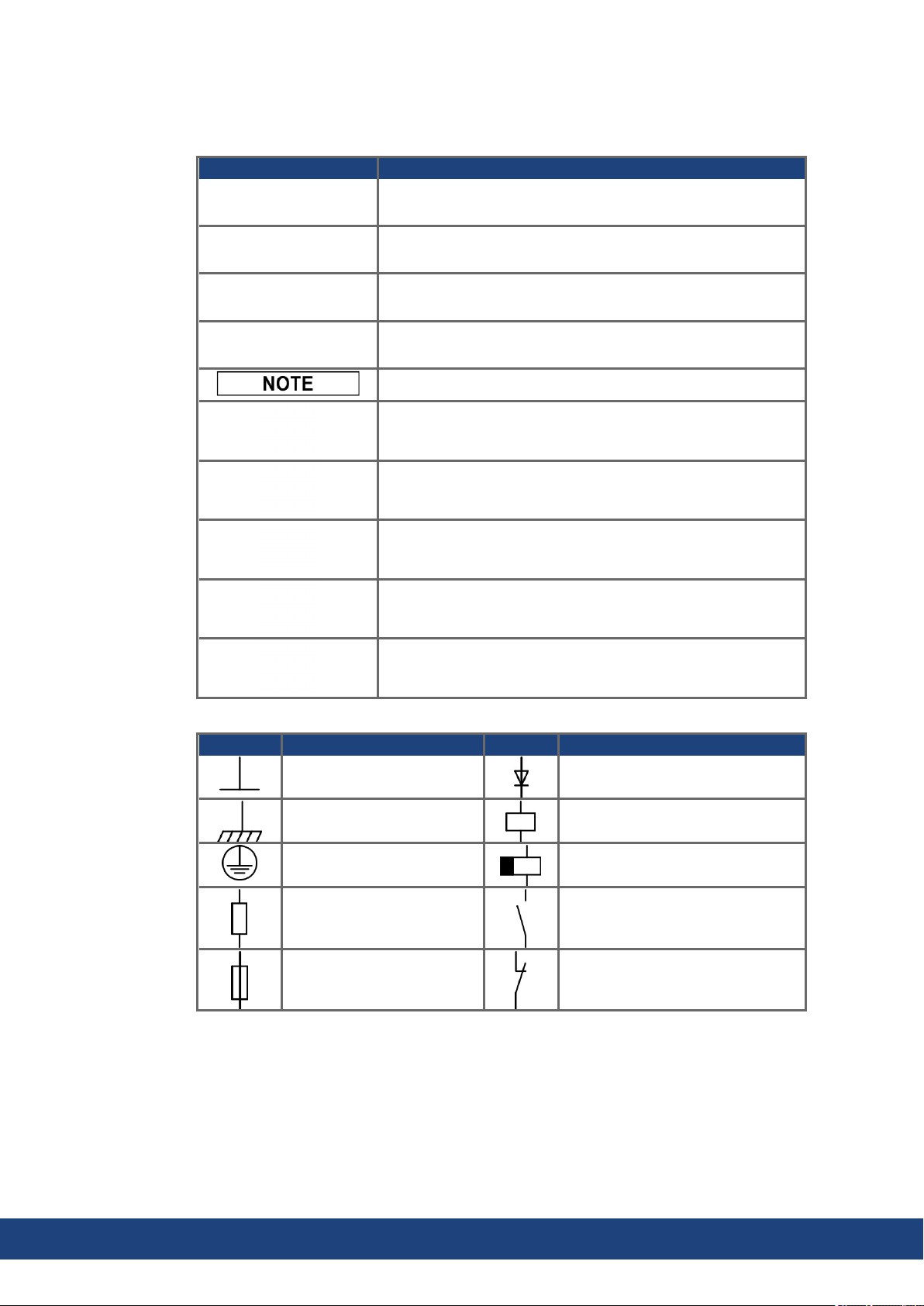
Warning Symbols
Symbol Indication
Indicates a hazardous situation which, if not avoided, will result
in death or serious injury.
Indicates a hazardous situation which, if not avoided, could result in death or serious injury.
Indicates a hazardous situation which, if not avoided, could result in minor or moderate injury.
Indicates situations which, if not avoided, could result in property damage.
This symbol indicates important notes.
Warning of a danger (general). The type of danger is specified
by the text next to the symbol.
Warning of danger from electricity and its effects.
Warning of danger from hot surface.
Warning of danger from suspended loads.
Warning of danger from automatic start.
Drawing symbols
Symbol Description Symbol Description
Signal ground Diode
Chassis ground Relay
Protective earth Relay switch off delayed
Resistor Normally open contact
Fuse Normally closed contact
10 Kollmorgen | kdn.kollmorgen.com | May 2020
Page 11

2.4 Abbreviations Used
Abbrev. Meaning
(➜ # xx) See page xx. Example (➜ # 53): see page 53.
AGND Analog ground
BTB/RTO Ready to operate
CAN Fieldbus (CANopen)
CLK Clock signal
COM Serial interface for a PC-AT
DGND Digital ground
Disk Magnetic storage (diskette, hard disk)
EEPROM Electrically erasable programmable memory
EMC Electromagnetic compatibility
EMI Electromagnetic interference
ESD Electrostatic discharge
F-SMA Fiber Optic Cable connector according to IEC 60874-2
INC Incremental Interface
LED Light-emitting diode
MB Megabyte
NI Zero pulse
PC Personal computer
PELV Protected low voltage
PL Performance Level
PLC Programmable logic controller
PWM Pulse width modultation
RAM Volatile memory
RB Brake (regen) resistor
RBext External brake resistor
RBint Internal brake resistor
RES Resolver
ROD A quad B encoder
SIL Safety Integrity Level
SIL CL Safety Integrity Level Claim Limit
SRAM Static RAM
SSI Synchronous serial interface
STO Safe Torque Off
V AC AC voltage
V DC DC voltage
S300 Instructions Manual | 2 General
Kollmorgen | kdn.kollmorgen.com | May 2020 11
Page 12

S300 Instructions Manual | 3 Safety
3 Safety
This section helps you to recognize and avoid dangers to people and objects.
3.1 You should pay attention to this
Specialist staff required!
Only properly qualified personnel are permitted to perform such tasks as transport, installation and setup. Qualified specialist staff are persons with expertise in transport, installation,
assembly, commissioning and operation of electrotechnical equipment.
Transport, storage, unpacking: only by personnel with knowledge of handling electrostatically sensitive components.
Mechanical installation: only by personnel with mechanical expertise.
Electrical installation: only by personnel with expertise in electrical engineering.
Basic tests / setup: only by personnel with expertise in electrical engineering and drive
technology.
The qualified personnel must know and observe ISO 12100 / IEC 60364 / IEC 60664 and
national accident prevention regulations.
Read the documentation!
Read the available documentation before installation and commissioning. Improper handling
of the devices can cause harm to people or damage to property. The operator of systems
using the drive system must ensure that all personnel who work with the drive read and understand the manual before using the drive.
Check Hardware Revision!
Check the Hardware Revision Number of the product (see product label). This number is the
link between your product and the manual. The product Hardware Revision Number must
match the Hardware Revision Number on the cover page of the manual.
Pay attention to the technical data!
Adhere to the technical data and the specifications on connection conditions. If permissible
voltage values or current values are exceeded, the devices can be damaged. Unsuitable
motor or wrong wiring will damage the system components. Check the combination of drive
and motor. Compare the rated voltage and current of the units.
Observe electrostatically sensitive components!
The devices contain electrostatically sensitive components which may be damaged by incorrect handling. Electrostatically discharge your body before touching the device. Avoid contact with highly insulating materials (artificial fabrics, plastic film etc.). Place the device on a
conductive surface.
Perform a risk assessment!
The manufacturer of the machine must generate a risk assessment for the machine, and take
appropriate measures to ensure that unforeseen movements cannot cause injury or damage
to any person or property. Additional requirements on specialist staff may also result from the
risk assessment.
12 Kollmorgen | kdn.kollmorgen.com | May 2020
Page 13

S300 Instructions Manual | 3 Safety
Automatic Restart!
The drive might restart automatically after power on, voltage dip or interruption of the supply
voltage, depending on the parameter setting. Risk of death or serious injury for humans working in the machine. If the parameter AENA is set to 1, then place a warning sign to the
machine (Warning: Automatic Restart at Power On) and ensure, that power on is not possible, while humans are in a dangerous zone of the machine. In case of using an undervoltage protection device, you must observe EN 60204-1.
Hot surface!
Drives may have hot surfaces during operation. The housing can reach temperatures above
80°C. Risk of minor burns! Measure the temperature, and wait until the housing has cooled
down below 40 °C before touching it.
Earthing!
It is vital that you ensure that the drive is safely earthed to the PE (protective earth) busbar in
the switch cabinet. Risk of electric shock. Without low-resistance earthing no personal protection can be guaranteed.
Leakage Current!
Since the leakage current to PE is more than 3.5 mA, in compliance with IEC61800-5-1 the
PE connection must either be doubled or a connecting cable with a cross-section >10 mm²
must be used. Deviating measures according to regional standards might be possible.
High voltages!
The equipment produces high electric voltages up to 900V. Do not open or touch the equipment during operation. Keep all covers closed.
During operation, S300 may have uncovered live sections, according to their level of enclosure protection.
Lethal danger exists at live parts of the device. Built-in protection measures such as insulation or shielding may not be removed. Work on the electrical installation may only be performed by trained and qualified personnel, in compliance with the regulations for safety at
work, and only with switched off mains supply, and secured against restart.
Never undo any electrical connections to the S300 while it is live. There is a danger of electrical arcing with damage to contacts and personal injury. Wait at least 5 minutes after disconnecting the product from the supply voltages (mains supply and 24V supply) before
touching potentially live sections of the equipment (such as contacts) or removing any connections.
Always measure the voltage in the DC bus link and wait until the voltage is below 50 V
before handling components.
Functional Safety
The STO safety implementation on the S300 is certified. The assessment of the safety functions according to EN13849 or EN 62061 must finally be done by the user.
Reinforced Insulation
Thermal sensors, motor holding brakes and feedback systems built into the connected motor
must have reinforced insulation (according to IEC61800-5-1) against system components
with power voltage, according to the required application test voltage. All Kollmorgen components meet these requirements.
Never modify the drive!
It is not allowed to modify the drive hardware without permission by the manufacturer. Opening the housing causes loss of warranty.
Kollmorgen | kdn.kollmorgen.com | May 2020 13
Page 14

S300 Instructions Manual | 3 Safety
3.2 Warning notes placed on the product
Residual Voltage.
Wait 5 minutes
after removing power.
If these signs are damaged, they must be replaced immediately.
14 Kollmorgen | kdn.kollmorgen.com | May 2020
Page 15

3.3 Use as Directed
The servo amplifiers are components which are built into electrical equipment or
machines, and can only be used as integral components of such equipment.
If the servo amplifiers are used in residential areas, or in business or commercial
premises, then additional filter measures must be implemented by the user.
Cabinet and Wiring
The servo amplifiers may only be operated in a closed switchgear cabinet, taking into
account the ambient conditions (➜ # 29) and the dimensions (➜ # 47). Ventilation or cooling may be necessary to prevent enclosure ambient from exceeding 40°C (104°F).
Use only copper wire. Wire size may be determined from EN 60204 (or table 310-16 of the
NEC 60°C or 75°C column for AWG size).
Power supply
The SERVOSTAR 300 family of servo amplifiers (overvoltage category III acc. to EN
61800-5-1) can be connected directly to symmetrically earthed (grounded) three-phase
industrial mains supply networks [TN-system, TT-system with earthed (grounded) neutral
point, not more than 42,000 rms symmetrical amperes,110V
ctively 208V
see (➜ # 58).
Periodic overvoltages between outer conductor (L1, L2, L3) and housing of the servo amplifier may not exceed 1000V (peak value). Transient overvoltages (< 50µs) between the
outer conductors may not exceed 1000V. Transient overvoltages (< 50µs) between outer
conductors and housing may not exceed 2000V.
-10%
...480V
S300 Instructions Manual | 3 Safety
...230V
+10%
maximum]. Connection to different mains supply networks
-10%
+10%
resped-
Motors
The SERVOSTAR 300 family of servo amplifiers is only intended to drive specific brushless synchronous servomotors, with closed-loop control of torque, speed and/or position.
The rated voltage of the motors must be at least as high as the DC bus link voltage of the
servo amplifier.
Functional Safety
Consider the specific "use as directed" information (➜ # 38) when you use the safety
function STO.
3.4 Prohibited Use
Other use than that described in chapter “Use as directed” is not intended and can lead to personnel injuries and equipment damage. The servo amplifier may not be used with a machine
that does not comply with appropriate national directives or standards. The use of the servo
amplifier in the following environments is also prohibited:
potentially explosive areas
environments with corrosive and/or electrically conductive acids, alkaline solutions, oils,
vapors, dusts
ships or offshore applications
The control of holding brakes by the S300 alone may not be used in applications, where functional safety is to be ensured with the brake.
Kollmorgen | kdn.kollmorgen.com | May 2020 15
Page 16

S300 Instructions Manual | 4 Product life cycle handling
4 Product life cycle handling
4.1 Transport
Transport the SERVOSTAR 300 in accordance with IEC 61800-2 as follows:
Only by qualified personnel in the manufacturer’s original recyclable packaging
Avoid shocks
Temperature: –25 to +70°C, max. 20K/hr rate of change,
class 2K3 acc. to EN61800-2, EN 60721-3-1
Humidity: max. 95% relative humidity, no condensation,
class 2K3 acc. to EN61800-2, EN 60721-3-1
If the packaging is damaged, check the unit for visible damage. In this case, inform the
shipper and the manufacturer.
The servo amplifiers contain electrostatically sensitive components which can be damaged
by incorrect handling. Discharge yourself before touching the servo amplifier. Avoid contact
with highly insulating materials (artificial fabrics, plastic films etc.). Place the servo amplifier
on a conductive surface.
4.2 Packaging
The S300 packaging consists of recyclable cardboard with inserts.
Dimensions (HxWxD): 115x365x275mm
Labeling : nameplate outside at the box
4.3 Storage
Store the S300 in accordance with IEC 61800-2 as follows:
Storage only in the manufacturer’s original recyclable packaging
Max. stacking height 8 cartons
Storage temperature: -25 to +55°C, max. rate of change 20°C / hour
class 1K4 acc. to EN61800-2, EN 60721-3-1
Storage humidity: 5 ... 95% relative humidity, no condensation
class 1K3 acc. to EN61800-2, EN 60721-3-1
Storage duration: Less than 1 year without restriction.
More than 1 year: capacitors must be re-formed before setting up and operating the servo
amplifier. To do this, remove all electrical connections and apply single-phase 230V AC
for about 30 minutes to the terminals L1 / L2.
4.4 Installation, setup and normal operation
In normal operation, the cabinet door must be closed and the device must not be touched.
Installation and setup information are given in
Chapter Mechanical installation (➜ # 45)
Chapter Electrical installation (➜ # 48)
Chapter Setup (➜ # 97)
Normal operation tested for environmental class 3K3 according to IEC 61800-2 (➜ # 29).
The manufacturer of the machine defines the necessary end user expertise based on the risk
assessment for the machine and describes the requirements for normal operation based on
the application.
16 Kollmorgen | kdn.kollmorgen.com | May 2020
Page 17

4.5 Decommissioning
Only professional staff who are qualified in electrical engineering are allowed to decommission parts of the system.
DANGER: Lethal Voltages!
There is a danger of serious personal injury or death by electrical shock or electrical arcing.
Switch off the main switch of the switchgear cabinet.
Secure the system against restarting.
Block the main switch.
Wait at least 5 minutes after disconnecting.
4.6 Maintenance and cleaning
The device does not require maintenance. Opening the device voids the warranty. The inside
of the unit can only be cleaned by the manufacturer.
Do not immerse or spray the device. Avoid that liquid enters the device.
To clean the device exterior:
1. Decommission the device (see chapter 4.5 "Decommissioning").
2. Casing: Clean with isopropanol or similar cleaning solution.
Caution : Highly Flammable! Risk of injury by explosion and fire.
Observe the safety notes given on the cleaning liquid package.
Wait at least 30 minutes after cleaning before putting the device back into operation.
3. Protective grill on fan: Clean with a dry brush.
S300 Instructions Manual | 4 Product life cycle handling
4.7 Disassembly
Only professional staff who are qualified in electrical engineering are allowed to disassemble
parts of the system.
1. Decommission the device (see chapter 4.5 "Decommissioning").
2. Check temperature.
3. Remove the connectors. Disconnect the potential earth connection last.
4. Demount: loosen the fastening screws. Remove the device.
CAUTION: High Temperature! Risk of minor burns. During operation, the heat sink of
the drive may reach temperatures above 80°C (176°F). Before touching the device,
check the temperature and wait until it has cooled below 40°C (104°F).
Kollmorgen | kdn.kollmorgen.com | May 2020 17
Page 18

S300 Instructions Manual | 4 Product life cycle handling
4.8 System Repair
Only professional staff who are qualified in electrical engineering are allowed to exchange
parts of the drive system.
CAUTION: Automatic Start! During replacement work a combination of hazards and mul-
tiple episodes may occur.
Work on the electrical installation may only be performed by trained and qualified personnel, in compliance with the regulations for safety at work, and only with use of prescribed personal safety equipment.
Exchange of the device
Only the manufacturer can repair the device. Opening the device voids the warranty.
1. Decommission the device (see chapter 4.5 "Decommissioning").
2. Demount the device (see chapter 4.7 "Disassembly").
3. Send the device to the manufacturer.
4. Install a new device as described in this manual.
5. Setup the system as described in this manual.
Exchange of other drive system parts
If parts of the drive system (for example cables) must be replaced, proceed as follows:
4.9 Disposal
1. Decommission the device (see chapter 4.5 "Decommissioning").
2. Exchange the parts.
3. Check all connections for correct fastening.
4. Setup the system as described in this manual.
To dispose the unit properly, contact a certified electronic scrap disposal merchant.
In accordance with the WEEE-2012/19/EU guideline and similar, the manufacturer accepts
returns of old devices and accessories for professional disposal. Transport costs are the
responsibility of the sender.
Contact Kollmorgen and clarify the logistics.
18 Kollmorgen | kdn.kollmorgen.com | May 2020
Page 19

5 Approvals
Certificates (CE, functional safety) can be found at the Kollmorgen Website.
5.1 Conformance with UL/cUL
This servo amplifier is listed under UL file number E217428.
UL (cUL)-certified servo amplifiers (Underwriters Laboratories Inc.) fulfil the relevant U.S.
and Canadian standard (in this case UL 840 and UL 508C). The UL certification relates only
to the mechanical and electrical construction design of the device.
This standards describe the fulfillment by design of minimum requirements for electrically
operated power conversion equipment, such as frequency converters and servo amplifiers,
which is intended to eliminate the risk of fire, electric shock, or injury to persons, being
caused by such equipment. The technical conformance with the standards is determined by
an independent UL inspector through the type testing and regular checkups.
Apart from the notes on installation and safety in the documentation, the customer does not
have to observe any other points in direct connection with the UL (cUL)-certification of the
equipment.
UL 508C: UL 508C describes the fulfillment by design of minimum requirements for electrically operated power conversion equipment, such as frequency converters and servo amplifiers, which is intended to eliminate the risk of fire being caused by such equipment.
UL 840: UL 840 describes the fulfillment by design of air and insulation creepage spacings
for electrical equipment and printed circuit boards.
S300 Instructions Manual | 5 Approvals
Markings Marquages
Use 60°C or 75°C copper wire only.
Use Class 1 wire only.
Tightening torque for field wiring terminals. X0, X8, X9: 0.5 - 0.6Nm (4.43 to
5.31 lbf in).
Use in a pollution degree 2 environment.
These devices provide solid state motor
overload protection at 130% of full load
current.
Integral solid state short circuit protection does not provide branch circuit
protection. Branch circuit protection
must be provided in accordance with the
National Electrical Code and any additional local codes.
These devices are not provided with
motor over-temperature sensing.
Suitable for use on a circuit capable of
delivering not more than 42kA rms symmetrical amperes for a max. voltage of
480 Vac.
The drives may be connected together
via the “common bus” (DC bus link)
based on the instructions on (➜ # 61) ff.
The devices may also be grouped from
the AC input side based on the max.
input fuse (e.g. 3xS346 with one common 6A fuse in line).
Utilisez un fil en cuivre 60°C ou 75 °C min..
Utilisez seulement un fil de classe 1.
Couples de serrage recommandée. X0, X8,
X9: 0.5 - 0.6Nm (4.43 to 5.31 lbf in).
Utilisation dans un environnement de pollution de niveau 2.
Ces variateurs offrent une protection contre
les surcharges de moteur à semi-conducteur à 130 % du courant FLA nominal.
Une protection de court-circuit à semi-conducteur intégrale ne fournit pas de protection de la dérivation. Il convient de
garantir une protection de la dérivation conforme au NEC (National Electrical Code) et
aux réglementations locales en vigueur, ou
aux directives équivalentes applicables.
Ces variateurs n’offrent pas de capteurs de
température excessive.
Ce produit est conçu pour une utilisation
sur un circuit capable de fournir 42 000
ampères symétriques (rms) maximum pour
480V.
Les variateurs peuvent être reliés entre eux
via le “bus commun CC” sur la base des
instructions (➜ # 61) ff. Les variateurs
peuvent être groupés d'entrée AC basé sur
le max. fusible d’entrée (par exemple
3xS346 avec un fusible de 6A commune).
Kollmorgen | kdn.kollmorgen.com | May 2020 19
Page 20

S300 Instructions Manual | 5 Approvals
5.2 Conformance with CE
The servo amplifiers have been tested by an authorized testing laboratory in a defined configuration, using the system components that are described in this documentation. Any divergence from the configuration and installation described in this documentation means that you
will be responsible for carrying out new measurements to ensure conformance with regulatory requirements.
Kollmorgen declares the conformity of the products SERVOSTAR 300(S300) with the following directives
EC Machinery Directive 2006/42/EU
EC EMC Directive 2014/30/EU
EC Low Voltage Directive 2014/35/EU
Concerning noise immunity the servo amplifier meets the requirements to the 2nd environmental category (industrial environment). For noise emission the amplifier meets the
requirement to a product of the category C2 (motor cable up to 10 m). With a motor cable
length from 10 m onwards, the servo amplifier meets the requirement to the category C3.
This product can cause high-frequency interferences in non industrial environments which
can require measures for interference suppression.
5.2.1 European Directives and Standards for the machine builder
Servo amplifiers are safety components that are intended to be incorporated into electrical
plant and machines for industrial use. When the servo amplifiers are built into machines or
plant, the amplifier must not be used until it has been established that the machine or equipment fulfills the requirements of the
EC Machinery Directive (2006/42/EU)
EC EMC Directive (2014/30/EU)
EC Low Voltage Directive (2014/35/EU)
Standards to be applied for conformance with EC Machinery Directive (2006/42/EU)
IEC 60204-1 (Safety and Electrical Equipment in Machines)
ISO 12100 (Safety of Machines)
The manufacturer of the machine must generate a risk assessment for the machine, and
must implement appropriate measures to ensure that unforeseen movements cannot cause
injury or damage to any person or property.
The machine manufacturer must check whether other standards or EC Directives must be
applied to the machine.
Standards to be applied for conformance with the Low Voltage Directive(2014/35/EU)
IEC 60204-1 (Safety and Electrical Equipment in Machines)
IEC 60439-1 (Low-voltage switchgear and controller assemblies)
Standards to be applied for conformance with the EMC Directive (2014/30/EU)
IEC 61000-6-1 / 2 (Interference Immunity in Residential & Industrial Areas)
IEC 61000-6-3 / 4 (Interference Generation in Residential & Industrial Areas)
The manufacturer of the machine is responsible for ensuring that it meets the limits required
by the EMC regulations. Advice on the correct installation for EMC can be found in this documentation.
We only guarantee the conformance of the servo system with the standards cited in this
chapter if the components (motor, cables, chokes etc.) are those supplied by us.
20 Kollmorgen | kdn.kollmorgen.com | May 2020
Page 21

S300 Instructions Manual | 5 Approvals
5.2.2 Functional Safety Conformance (STO) according to EC Machinery Directive
The S300 servo amplifier offers a single channel STO function (Safe Torque Off) that can be
used as a functional safe restart lock.
The safetys concept is certified. The safety circuit concept for realizing the safety function
"Safe Torque Off" in the servo amplifiers S300 is suited for SIL CL 2 according to IEC 62061
and PLd according to ISO 13849-1.
The subsystems (servo amplifiers) are totally described for safety technics with the characteristic data SIL CL, PFHD and TM.
Device Operation mode EN 13849-1 EN 62061 PFHD [1/h] TM [Year]
STO-Enable
single channel PLd SIL CL 2 1.50E-07 20
5.2.3 Conformance with RoHS
The device is manufactured in conformance with RoHS Directive 2011/65/EU with delegated
directive 2015/863/EU for installation into a machine.
5.2.4 Conformance with REACH
EU Regulation no. 1907/2006 deals with the registration, evaluation, authorization and restriction of chemical substances 1 (abbreviated to "REACH").
The device does not contain any substances (CMR substances, PBTsubstances, vPvB substances and similar hazardous substances stipulated in individual cases based on scientific
criteria) above 0.1 mass percent per product that are included on the candidate list.
5.3 Conformance with EAC
EAC is the abbreviation for Eurasian Conformity. The mark is used in the states of the Eurasian Customs Union (Russia, Belarus, Kazakhstan) similar to the European CE mark.
Kollmorgen declares, that the device has passed all required conformity procedures in a member state of the Eurasian Customs Union, and that the device meets all technical requirements requested in the member states of the Eurasian Customs Union:
Low voltage (TP TC 020/2011)
Electromagnetic Compatibility (TP TC 004/2011)
Contact: SERVOSTAR LLC. , Bld.1, Semyonovskaya nab. 2/1, RU-105094 Moskau
Kollmorgen | kdn.kollmorgen.com | May 2020 21
Page 22
S300 Instructions Manual | 6 Package
6 Package
6.1 Package Supplied
When you order a SERVOSTAR 300 series amplifier (Order codes (➜ # 137)), you will
receive:
S3xx
Mating connectors X0, X3, X4, X8
Mating Connector X9 (with SERVOSTAR 303-310 only ) (S3xx6)
S300 Safety Notes printed
All documentation in PDF format on CD-ROM
Setup software DRIVE.EXE on CD-ROM
The mating SubD connectors are not part of the package!
Accessories: (must be ordered separately; description see accessories manual)
l Hybrid motor cable (prefabricated) for single cable connection
l motor cable (prefabricated) with special shield clamp, or both power connectors sep-
arately, with the motor cable as a cut-off length
l feedback cable (prefabricated) or both feedback connectors separately, with the feedback
cable as a cut-off length
l motor choke 3YL/3YLN, for motor cables longer than 25 meters
l external brake resistor BAR(U), capacity module KCM
l communication cable to the PC (➜ # 95) for setting parameters from a PC
l power cable, control cables, fieldbus cables (as cut-off lengths)
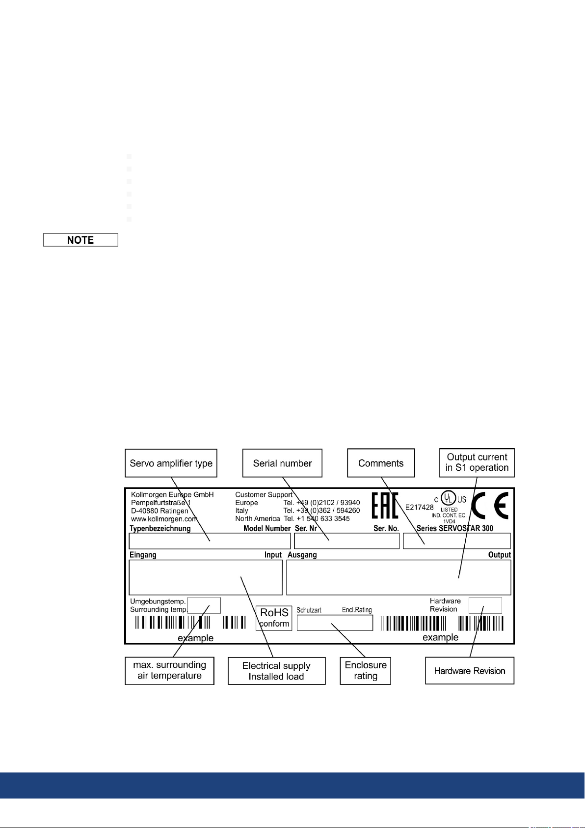
6.2 Nameplate
The nameplate is attached to the side of the servo amplifier. The information described below
is printed in the individual fields. Picture similar to the original nameplate.
22 Kollmorgen | kdn.kollmorgen.com | May 2020
Page 23
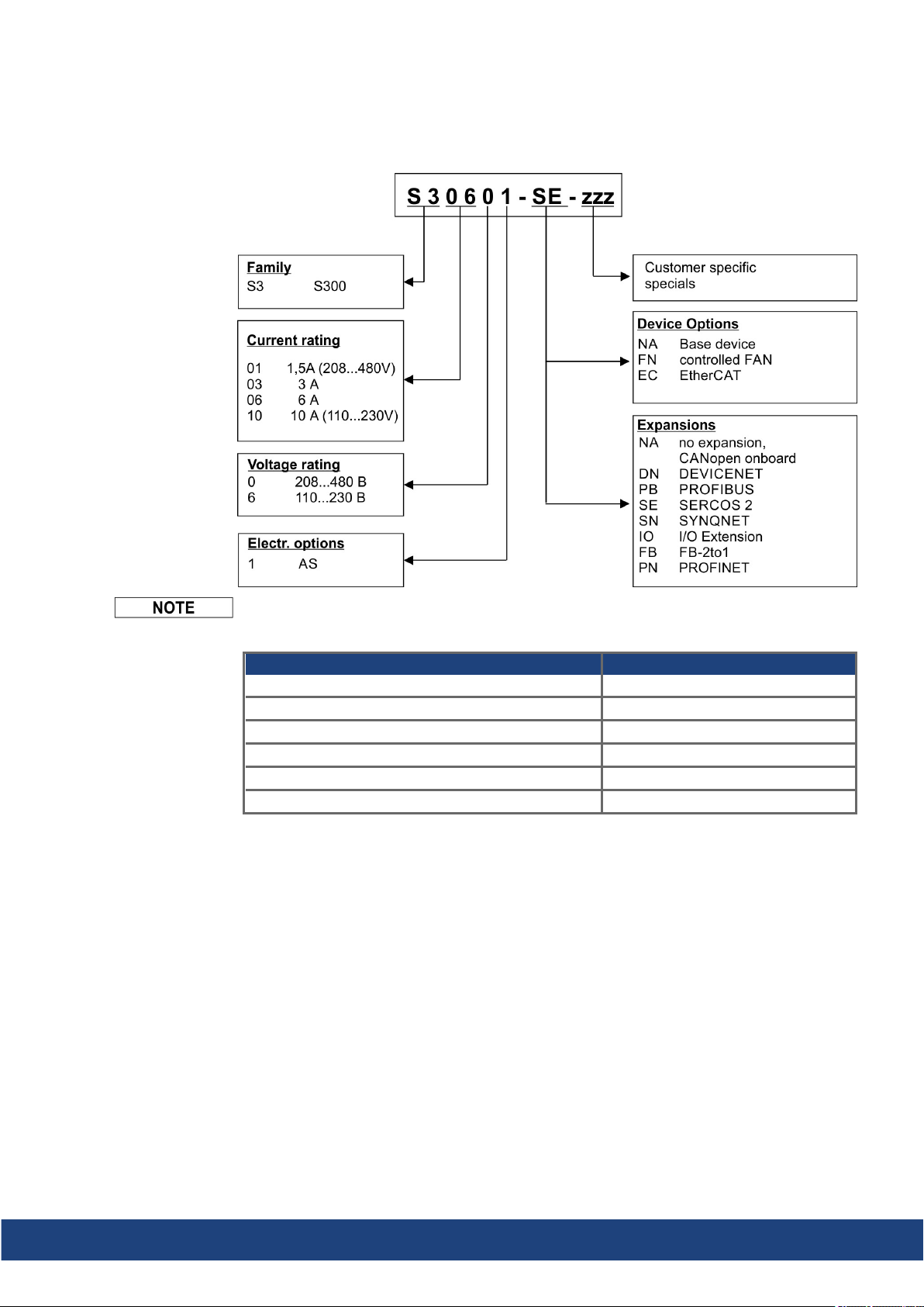
6.3 Part Number Scheme
Use the part number scheme for product identification only, not for the order process,
because not all combinations of features are possible, always.
S300 Instructions Manual | 6 Package
Expansions and device options cannot be combined.
Comparison device name -> part number
Device Name Part Number
SERVOSTAR 303 S30361-NA
SERVOSTAR 306 S30661-NA
SERVOSTAR 310 S31061-NA
SERVOSTAR 341 S30101-NA
SERVOSTAR 343 S30301-NA
SERVOSTAR 346 S30601-NA
Kollmorgen | kdn.kollmorgen.com | May 2020 23
Page 24

S300 Instructions Manual | 7 Technical description
7 Technical description
7.1 The SERVOSTAR 300 family of digital servo amplifiers
Standard version
Two voltage classes with large nominal voltage range
1 x 110 V
3 x 208 V
… 3 x 230 V
-10%
… 3 x 480 V
-10%
+10%
(SERVOSTAR 303-310, S3xx6)
+10%
(SERVOSTAR 341-346, S3xx0)
Overvoltage category III acc. to EN 61800-5-1
Shielding connection directly on the servo amplifier
Two analog inputs onboard
CANopen onboard (default: 500 kBaud), for integration in CAN-bus systems and for setting parameters for several drives via the PC interface of one of the amplifiers
Slot for an expansion card
RS232 and pulse direction interface onboard
Restart lock STO for functional safety onboard (➜ # 38)
Intelligent position controller onboard
Multi feedback support
Synchronous servomotors, linear motors, asynchronous motors, high frequency spindles
and DC motors can be used
Power section
Directly on grounded 3-phase supply, 110V
-10%
or 230V
up to 480V
-10%
+10%
TN-network or TT-network with grounded neutral point, 42kA max. symmetrical current
rating, connection to other supply types only via isolating transformer, (➜ # 58)
B6 bridge rectifier, integral supply filter and soft-start circuit
Single-phase supply operation possible (e.g. for setup)
Fusing: (e.g. fusible cutout) to be provided by the user
Shielding: all shielding connections are made directly on the amplifier
Output stage: IGBT module with floating current measurement
Brake circuit with dynamic distribution of the regenerated power between several amplifiers on the same DC bus link circuit. Internal brake resistor as standard, external brake
resistors if required.
DC bus link voltage 135 … 450 V DC or 260 … 900 V DC, can be connected in parallel.
Interference suppression filters are integrated for the electrical supply feed and the 24V
auxiliary supply voltage (with motor cable 10m for C2 as per EN 61800-3, with motor
cable > 10m for C3 as per EN 61800-3).
Integrated safety
Appropriate insulation/creepage distances and electrical isolation ensure safe electrical
separation, as per EN 61800-5-1, between the power input / motor connections and the
signal electronics.
Soft-start, overvoltage detection, short-circuit protection, phase-failure monitoring.
Temperature monitoring of the servo amplifier and motor (if our motors and prefabricated
cables are used).
24 Kollmorgen | kdn.kollmorgen.com | May 2020
Page 25

S300 Instructions Manual | 7 Technical description
Auxiliary supply voltage 24V DC
Electrically isolated, internal fusing, from an external 24V DC power supply unit with, for
instance, isolating transformer or uninterruptible power supply.
Operation and parameter setting
With our user-friendly setup software, for setup via the serial interface of a PC.
If no PC is available: direct operation by two keys on the servo amplifier and a 3-character
LED display.
Fully programmable via RS232 interface.
Completely digital control
Digital current controller (space vector, pulse-width modulation, 62.5 μs)
Adjustable digital speed controller (62.5 μs)
Integrated position controller, with adaptation possibilities for all applications (250 μs)
Integrated step/direction interface for connecting a servomotor to a stepper controller
Evaluation of resolver signals and sine-cosine signals of high-resolution encoders
Encoder emulation (incremental, compatible with A quad B or SSI)
Comfort functions
2 programmable analog inputs
4 programmable digital inputs
2 programmable digital outputs
programmable logical combinations of digital signals
Device Options
Option EtherCAT, cannot be inserted later, (➜ # 133)
Option FAN, ventilator control, cannot be inserted later, (➜ # 134)
Expansions
I/O-14/08 expansion card,, (➜ # 116)
PROFIBUS DP expansion card,, (➜ # 119)
sercos® II expansion card,, (➜ # 120)
DeviceNet expansion card,, (➜ # 122)
SynqNet expansion card,, (➜ # 125)
FB-2to1 expansion card,, (➜ # 127)
PROFINET expansion card, (➜ # 129)
-2CAN- expansion module, separated connectors for CAN-bus and RS232, (➜ # 131)
Several third-party expansion cards (ModBus, LightBus, FIP-IO etc. please contact the
manufacturer for further information)
Kollmorgen | kdn.kollmorgen.com | May 2020 25
Page 26

S300 Instructions Manual | 7 Technical description
7.2 Technical Data
7.2.1 Technical Data 110 / 230 V (Types S3_ _6_)
Rated data DIM S303 S306 S310
Order code - S30361 S30661 S31061
Rated supply voltage (L1,L2,L3)
(grounded system, phase-phase)
V~
1 x 110V
3 x 110V
-10%
-10%
... 230V
... 230V
Rated installed load for continuous operation at 230V kVA 1.1 2.4 4
Permitted switch on/off frequency 1/h 30
Max DC bus link voltage V= 450
Rated output current (rms value, ± 3%)
at 1x115V (observe (➜ # 60)) Arms 3.5* 8* 10*
at 1x230V (observe (➜ # 60)) Arms 3* 6* 10*
at 3x115V Arms 3.5 8 10
at 3x230V Arms 3 6 10
Peak output current (max. ca. 5s, ± 3%)
at 1x115V, 1x230V (observe (➜ # 60)) Arms 9* 15* 20*
at 3x115V, 3x230V Arms 9 15 20
Clock frequency of the output stage kHz 8 /16 with 50% derating
Voltage rise speed dU/dt (observe notes on page (➜ # 64))
at 1x115V kV/µs 3.0
at 1x230V kV/µs 3.3
at 3x115V kV/µs 3.0
at 3x230V kV/µs 3.3
Technical data for brake circuit - (➜ # 31)
Overvoltage protection threshold at 115 V / 230 V V 235 / 455
Motor inductance min.
at 1x115V mH 3.7 3.7 3.7
at 1x230V mH 4.3 4.3 4.3
at 3x115V mH 2.1 1.3 1.0
at 3x230V mH 4.3 2.6 1.9
Motor inductance max. mH Consult our customer support
Form factor of the output current
(rated conditions, min. load inductance)
- 1.01
Bandwidth of subordinate current controller kHz > 1.2
Residual voltage drop at rated current V 4
Quiescent dissipation, output stage disabled W 12
Dissipation at rated current (incl. power
supply losses, without brake dissipation)
W 35 60 90
Noise emission max. dB(A) 25 45
Mechanical
Weight kg 2.7
Height without connectors mm 270 279
Width mm 70
Depth without/with connectors mm 171 / <200
+10%
+10%
, 50/60 Hz
, 50/60 Hz
*in single-phase applications nom./peak current is limited to value below nominal value.
This depends on motor constant Kt and motor speed (➜ # 60).
26 Kollmorgen | kdn.kollmorgen.com | May 2020
Page 27

S300 Instructions Manual | 7 Technical description
7.2.2 Technical Data 230V ... 480 V (types S3_ _0_)
Rated data DIM S341 S343 S346
Order code - S30101 S30301 S30601
Rated supply voltage (L1,L2,L3)
(grounded system, phase-phase)
V~
3 x 208V
-10%
... 480V
Rated installed load for continuous operation at 400V kVA 1.2 2.5 5
Permitted switch on/off frequency 1/h 30
Max DC bus link voltage V= 900
Rated output current (rms value, ± 3%)
at 3x208V Arms 2 5 6
at 3x230V Arms 2 5 6
at 3x400V Arms 1.5 4 6
at 3x480V Arms 1.5 3 6
Peak output current (max. ca. 5s, ± 3%)
at 3x208V...3x480V Arms 4.5 7.5 12
Clock frequency of the output stage kHz 8 /16 with 50% derating
Voltage rise speed dU/dt (observe notes on page (➜ # 64))
at 3x208V kV/µs 3.0
at 3x230V kV/µs 3.3
at 3x400V kV/µs 5.7
at 3x480V kV/µs 6.9
Technical data for brake circuit - (➜ # 31)
Overvoltage protection threshold
at 3x230V V 455
at 3x400V V 800
at 3x480V V 900
Motor inductance min.
at 3x208V mH 7.7 4.6 2.9
at 3x230V mH 8.5 5.1 3.2
at 3x400V mH 14.8 8.9 5.6
at 3x480V mH 17.8 10.7 6.7
Motor inductance max. mH Consult our customer support
Form factor of the output current
(rated conditions, min. load inductance)
- 1.01
Bandwidth of subordinate current controller kHz > 1.2
Residual voltage drop at rated current V 5
Quiescent dissipation, output stage disabled W 12
Dissipation at rated current (incl. power
supply losses, without brake dissipation)
W 40 60 90
Noise emission max. dB(A) 25 45
Mechanical
Weight kg 2.7
Height without connectors mm 270 279
Width mm 70
Depth without/with connectors mm 171 / <230
+10%
, 50/60 Hz
Kollmorgen | kdn.kollmorgen.com | May 2020 27
Page 28

S300 Instructions Manual | 7 Technical description
7.2.3 Inputs / outputs, Auxiliary voltage
Interface Electr. data
Analog inputs 1, 2 (resolution 14/12 bit) ±10V
Max. common-mode voltage ±10V
Digital control inputs as per EN 61131-2 type1, max. 30VDC
Digital control outputs, active high open Emitter, max. 30VDC, 10mA
BTB/RTO output, relay contacts
Auxiliary supply voltage, electrically isolated,
without motor brake / fan
Auxiliary supply voltage, electrically isolated,
with motor brake / fan
Min./max. output current to brake 0.15A / 1.5A
7.2.4 Connectors
max. 30VDC, max 42VAC
500mA
20V - 30V
1A
24V (-0% +15%)
2.5A (check voltage drop !)
Connector Type max. cross
Control signals X3, X4 Mini-Combicon 1.5 mm² 4 A 160 V
S303-310: Power X0,X8,X9 Classic-Combicon 2.5 mm² 12 A 630V
S341-346: Power X0, X8, X9 Power-Combicon 4 mm² 16 A 1000 V
Resolver input X2 SubD 9pin (female) 0.5 mm² 1 A <100 V
Encoder input X1 SubD15pin (female) 0.5 mm² 1 A <100 V
PC interface, CAN X6 SubD 9pin (male) 0.5 mm² 1 A <100 V
Encoder emulation X5 SubD 9pin (male) 0.5 mm² 1 A <100 V
*1 single-line connection
*2 single-line connection with recommended conductor cross section (➜ # 29)
*3 rated voltage with pollution level 2
7.2.5 Recommended Tightening Torques
Connector Recommended torque
X0, X8, X9 0.5 to 0.6 Nm (4.43 to 5.31 in lbf)
Ground bolt 3.5 Nm (31 in lbf)
7.2.6 Fusing
Internal Fusing
section
*1
permitted
current
permitted
*2
tension
*3
Circuit internal fuse
Auxiliary supply 24V 3.15 A
Brake resistor electronic
External fusing
Fusible cutouts or similar S303 / S341 / S343 S306 / S310 / S346
AC supply F
24V supply F
Brake resistor F
N1/2/3
H1/2/3
B1/2
European fuses: gRL or gL 400V/500V, T means time-delay,
US fuses: class RK5/CC/J/T, 600VAC 200kA, time-delay
* for example Bussmann FWP-xx
28 Kollmorgen | kdn.kollmorgen.com | May 2020
6 A 10 A
max. 8 A
6 A* 6 A*
Page 29

S300 Instructions Manual | 7 Technical description
7.2.7 Ambient Conditions, Ventilation and Mounting Position
Storage, hints (➜ # 16)
Transport, hints (➜ # 16)
Mains power supply
Aux. power supply
without brake and fan
with brake or fan
Surrounding air temperature in operation
Humidity in operation rel. humidity 85%, no condensation, class 3K3
Site altitude up to 1000m a.m.s.l. without restriction
Pollution level Pollution level 2 to EN 60664-1
Vibrations Class 3M2 according to IEC 60721-3-3
Enclosure protection IP 20 according to EN60529
Mounting position generally vertical (➜ # 46)
Ventilation
S303 und S341
all other types
S303-S310:
1x110V-10% …1x230V+10%, 50/60 Hz
3x110V-10% …3x230V+10%, 50/60 Hz
S341-S346:
3x208V-10% ...3x 480V+10%, 50/60 Hz
20 V DC ... 30 V DC
24 V DC (-0% +15%),check voltage drop
0 to +40°C (32 to 104°F) at rated data
+40 to +55°C (113 to 131°F) with power derating 2.5% / K
1000 — 2500m a.m.s.l. with power derating 1.5%/100m
natural convection
built-on fan (optionally controlled, Option FN (➜ # 134))
Make sure that there is sufficient forced ventilation within
the switchgear cabinet.
7.2.8 Conductor cross-sections
Recommendations for cables (material and construction (➜ # 52)):
Interface Cross section Techn. Requirements
ACconnection 1.5 mm² 600V,80°C
DDC bus link
Brake resistor
Motor cables up to 25m,
motor choke
Motor cables 25m to 50 m,
motor choke 3YL/3YLN
Resolver, motor thermal control
Encoder, motor thermal control 7x2x0.25 mm², max. 50m* twisted pairs, shielded
ComCoder, motor thermal control 8x2x0.25 mm², max. 25m twisted pairs, shielded
Setpoints, AGND 0.25 mm², max. 30m twisted pairs, shielded
Control signals, BTB, DGND 0.5 mm², max. 30m
Holding brake (motor) min. 0.75 mm²
+24 V / DGND max. 2.5 mm² check voltage drop
2.5 mm²
1..1.5 mm², max. 25 m
1 mm², 25 - 50m*
4x2x0.25 mm²,
max.100m*
For multi-axis systems, observe the specific operating
conditions for your system. To reach the max. permitted
cable length, observe cable requirements (➜ # 52).
1000V, 80°C,
shielded for lengths >0.20m
600V,80°C, shielded,
capacitance <150pF/m
600V,80°C,shielded,
capacitance<150pF/m
twisted pairs, shielded,
capacitance<120pF/m
600V, 80°C, shielded,
check voltage drop
* Kollmorgen North America supplies cables up to 39 meters, Europe up to max. length
Kollmorgen | kdn.kollmorgen.com | May 2020 29
Page 30
S300 Instructions Manual | 7 Technical description
7.3 Motor holding brake
A 24V / max.1.5A holding brake in the motor can be controlled directly by the amplifier.
No functional safety!
Danger by falling load (in case of suspended load, vertical axes). An additional mechanical
brake is required for funktional safety, which must be safely operated.
The brake only works with sufficient voltage level (➜ # 28). Check voltage drop, measure
the voltage at brake input and check brake function (brake and no brake).
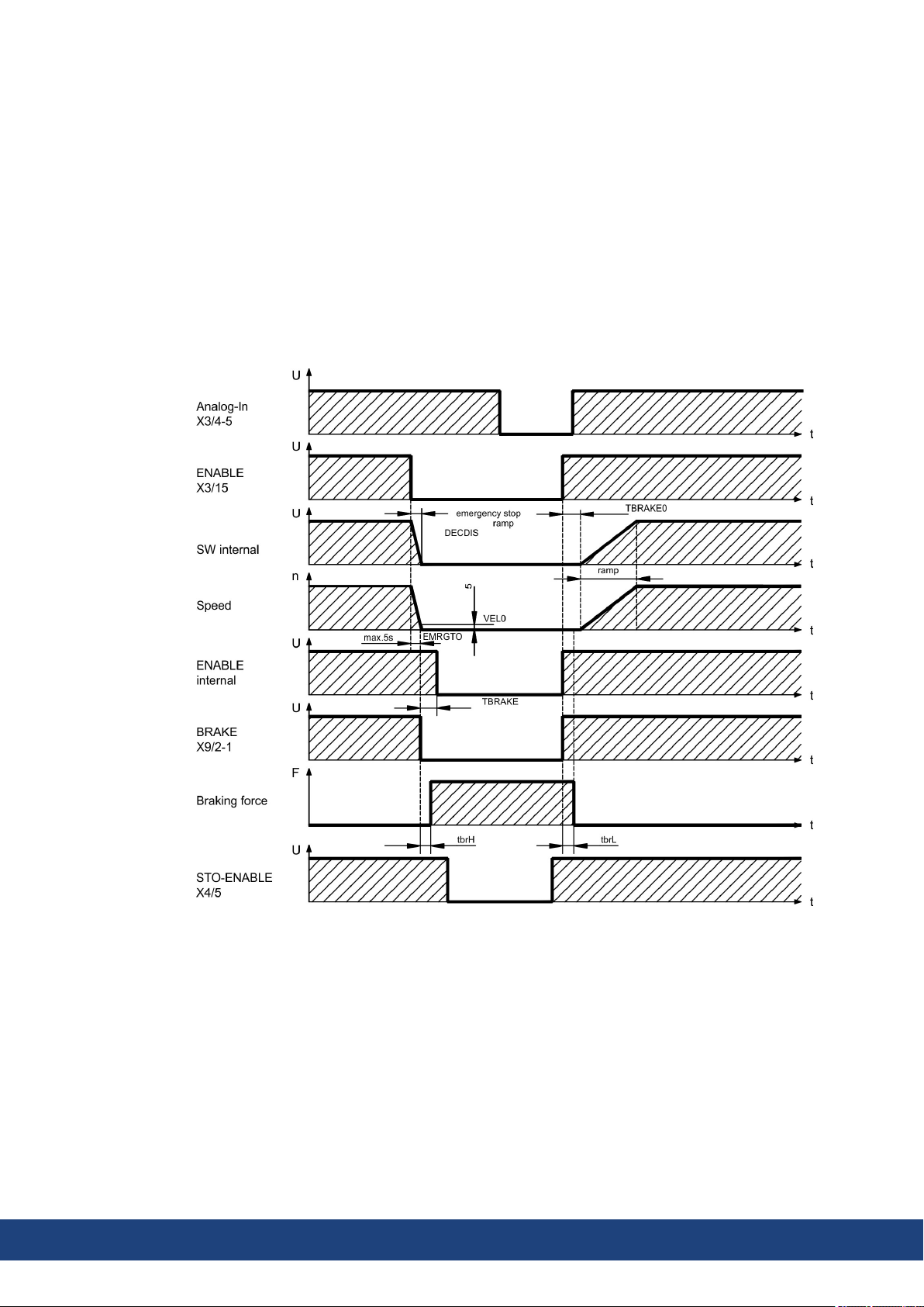
The brake function must be enabled through the BRAKE setting (screen page: Motor). In the
diagram below you can see the timing and functional relationships between the ENABLE signal, speed setpoint, speed and braking force. All values can be adjusted with parameters, the
values in the diagram are default values.
During the internal ENABLE delay time of 100ms (DECDIS), the speed setpoint of the servo
amplifier is internally driven down an adjustable ramp to 0V. The output for the brake is
switched on when the speed has reached 5 rpm (VELO), at the latest after 5 seconds
(EMRGTO).
The release delay time (tbrH) and the engage delay time (tbrL) of the holding brake that is built
into the motor are different for the various types of motor (see motor manual), the matching
data are loaded from the motor database when the motor is selected.
A description of the interface can be found on page (➜ # 64).
30 Kollmorgen | kdn.kollmorgen.com | May 2020
Page 31

7.4 LED display
A 3-character LED-Display indicates the status of the amplifier after switching on the 24 V
supply (➜ # 110). When the keys on the front panel are used, the parameter and function
numbers are shown, as well as the numbers for any errors and warnings that may occur (➜ #
112).
7.5 Grounding system
AGND - analog inputs, internal analog ground, Encoder emulation, RS232, CAN
DGND - 24V-IO, digital inputs and digital outputs, optically isolated
7.6 Dynamic braking (brake circuit)
During dynamic braking with the aid of the motor, energy is fed back into the servo amplifier.
This regenerative energy is dissipated as heat in the brake resistor. The brake resistor is
switched in by the brake circuit.
The setup software can be used to adapt the brake circuit (thresholds) according to the electrical supply voltage.
Our customer service can help you with the calculation of the brake power that is necessary
for your system. A simple method is described in the "KDN".
A description of the interface can be found on page (➜ # 61).
S300 Instructions Manual | 7 Technical description
Functional description:
1. Individual amplifiers, not coupled through the DC bus link circuit (DC+, DC-)
When the energy fed back from the motor has an average or peak power that exceeds the preset level for the brake power rating, then the servo amplifier generates the warning “n02 brake
power exceeded” and the brake circuit is switched off.
The next internal check of the DC bus link voltage (after a few milliseconds) detects an overvoltage and the output stage is switched off, with the error message “Overvoltage F02” (➜ #
112).
The BTB/RTO contact (terminals X3/2,3) will be opened at the same time (➜ # 94).
2. Several servo amplifiers coupled through the DC bus link (DC+, DC-)
Using the built-in brake circuit, several amplifiers (even with different current ratings) can be
operated off a common DC bus link, without requiring any additional measures.
The combined (peak and continuous) power of all amplifiers is always available. The switchoff on overvoltage takes place as described under 1. (above) for the amplifier that has the lowest switch-off threshold (resulting from tolerances).
Technical data of the brake circuits dependent on the amplifiers type and the mains voltage
situation see table on the next page.
Kollmorgen | kdn.kollmorgen.com | May 2020 31
Page 32

S300 Instructions Manual | 7 Technical description
Technical Data:
Brake circuit Supply voltage / V
Type Rated data DIM 115 230 400 480
Switch-on (upper) threshold of brake circuit V 200 400
S303
(S30361)
Overvoltage F02 V 235 455
Internal brake resistor (RBint) Ohm 66 66
Continuous power for internal resistor (RBint) W 20 20
Max. brake power (average for 1s) kW 0,4 0,35
Pulse brake power kW 0,84 3
External brake resistor (RBext), optional Ohm 66 66
Continuous power for external resistor (RBext) kW 0,3 0,3
Switch-on (upper) threshold of brake circuit V 200 400
S306
(S30661)
S310
(S31061)
Overvoltage F02 V 235 455
Internal brake resistor (RBint) Ohm 66 66
Continuous power for internal resistor (RBint) W 50 50
Max. brake power (average for 1s) kW 0,84 0,88
Pulse brake power kW 0,84 3
External brake resistor (RBext), optional Ohm 66 66
Continuous power for external resistor (RBext) kW 1 1
Switch-on (upper) threshold of brake circuit V
S341
(S30101)
Overvoltage F02 V 455 800 900
Internal brake resistor (RBint) Ohm 91 91 91
Continuous power for internal resistor (RBint) W 20 20 20
Max. brake power (average for 1s) kW 0,35 0,33 0,34
Pulse brake power kW 2,1 7 9
External brake resistor (RBext), optional Ohm 91 91 91
Continuous power for external resistor (RBext) kW 0,3 0,3 0,3
Switch-on (upper) threshold of brake circuit V
S343
(S30301)
S346
(S30601)
Overvoltage F02 V 455 800 900
Internal brake resistor (RBint) Ohm 91 91 91
Continuous power for internal resistor (RBint) W 50 50 50
Max. brake power (average for 1s) kW 0,91 0,86 0,85
Pulse brake power kW 2,1 7 9
External brake resistor (RBext), optional Ohm 91 91 91
Continuous power for external resistor (RBext) kW 1,0 1,0 1,0
—
—
400 720 840
—
400 720 840
—
Suitable external brake resistors can be found in our accessories manual.
32 Kollmorgen | kdn.kollmorgen.com | May 2020
Page 33

7.7 Switch-on and switch-off behavior
This chapter describes the switch-on and switch-off behavior of the S700 and the steps
required to achieve operational stopping or emergency stop behavior that complies with
standards.
The servo amplifier’s 24 V supply must remain constant.
The ASCII commands ACTFAULT (error response, also depends on the specific error, see
ERRCODE) and STOPMODE (Enable signal response) dictate how the drive will behave.
S300 Instructions Manual | 7 Technical description
ACTFAULT &
STOPMODE
0 Motor coasts to a standstill in an uncontrolled manner
1 (default) Motor is braked in a controlled manner
Behavior during a power failure
The servo amplifiers use an integrated circuit to detect if one or more input phases (power
supply feed) fail. The behavior of the servo amplifier is set using the setup software:
Under “Response to Loss of Input Phase” (PMODE) on the Basic Setup screen, select:
Error message if the servo amplifier is to bring the drive to a standstill: Error message F19 is
output if an input phase is missing. The servo amplifier is disabled and the BTB contact
opens. Where the factory setting is unchanged (ACTFAULT=1), the motor is braked using
the set “EMERGENCY STOP RAMP”.
Warning if the higher-level control system is to bring the drive to a standstill: Warning n05
is output if an input phase is missing, and the motor current is limited to 4 A. The servo
amplifier is not disabled. The higher-level control system can now selectively end the current cycle or start bringing the drive to a standstill. Therefore, the error message “MAINS
BTB, F16" is output on a digital
Error message if the servo amplifier is to bring the drive to a standstill: Error message
F19 is output if an input phase is missing. The servo amplifier is disabled and the BTB contact opens. Where the factory setting is unchanged (ACTFAULT=1), the motor is braked
using the set “EMERGENCY STOP RAMP”.
Behavior: (see also ASCII reference in the Online Help of the
setup software)
Behavior when undervoltage threshold is reached
If the undervoltage threshold is undershot in the DC bus link (the threshold value depends on
the type of servo amplifier), the error message “UNDERVOLTAGE, F05" is displayed. The
drive response depends on the ACTFAULT and STOPMODE setting.
Behavior with enabled “holding brake” function
Servo amplifiers with an enabled holding brake function have a special procedure for switching off the output stage (➜ # 30). Removing the ENABLE signal triggers electrical braking.
As with all electronic circuits, the general rule applies that there is a possibility of the internal
“holding brake” module failing. Functional safety, e.g. with hanging load (vertical axes),
requires an additional mechanical brake which must be safely operated.
Behavior of the safety function STO
With the functional safe restart lock STO, the drive can be secured on standstill using its
internal electronics so that even when power is being supplied, the drive shaft is protected
against unintentional restart. The chapter “Safety function STO” describes how to use the
STO function. See (➜ # 38) onwards.
Kollmorgen | kdn.kollmorgen.com | May 2020 33
Page 34

S300 Instructions Manual | 7 Technical description
7.7.1 Behavior in standard operation
The behavior of the servo amplifier always depends on the current setting of a number of different parameters (e.g., ACTFAULT, VBUSMIN, VELO, STOPMODE, see Online Help).
The diagram below illustrates the correct functional sequence for switching the servo amplifier on and off.
Devices which are equipped with a selected “Brake” function use a special sequence for
switching off the output stage (➜ # 30).
The built-in safety function STO can be used to switch off the drive, so that functional safety
is ensured at the drive shaft (➜ # 38) .
34 Kollmorgen | kdn.kollmorgen.com | May 2020
Page 35

S300 Instructions Manual | 7 Technical description
7.7.2 Behavior in the event of an error (with standard setting)
The behavior of the servo amplifier always depends on the current setting of a number of different parameters (e.g., ACTFAULT, VBUSMIN, VELO, STOPMODE, see Online Help).
Uncontrolled coasting!
Some faults (see ERRCODE ) force the output stage to switch-off immediately, independent
from the ACTFAULT setting. Danger of injury by uncontrolled coasting of the load. An additional mechanical brake is required for functional safety, which must be safely operated.
The diagram shows the startup procedure and the procedure that the internal control system
follows in the event of motor overtemperature, assuming that the standard parameter settings apply. Fault F06 does not switch-off the output stage immediately, with ACTFAULT=1
a controlled emergency brake is started first.
(F06 = error messages "Motor Temperature")
Even if there is no intervention from an external control system (in the example, the ENABLE
signal remains active), the motor is immediately braked using the emergency stop ramp if the
error is detected and assuming that no changes have been made to the factory setting
(ACTFAULT=1).
Kollmorgen | kdn.kollmorgen.com | May 2020 35
Page 36

S300 Instructions Manual | 7 Technical description
7.8 Stop-, Emergency Stop-, Emergency Off Function to IEC 60204
With the functional safe, certified function STO (➜ # 38) the drive can be secured on standstill (torque-free) using its internal electronics so that even when power is being supplied, the
drive shaft is protected against unintentional restart (up to SIL CL3 according to IEC 62061,
PLe according to ISO 13849-1).
The parameters “STOPMODE” and “ACTFAULT” must be set to 1 in order to implement the
stop and emergency stop categories. If necessary, change the parameters via the terminal
screen of the setup software and store the data in the EEPROM.
Examples for implementation can be found in the KDN on page Stop and Emergency Stop
Function.
7.8.1 Stop
The Stop function is used to shut down the machine in normal operation. The Stop functions
are defined by IEC 60204.
Category 0: Shut-down by immediate switching-off of the energy supply to the drive
machinery (i.e. an uncontrolled shut-down); this can be done with the built-in
STO functionality (➜ # 38) .
Category 1: A controlled shut-down , whereby the energy supply to the drive machinery
is maintained to perform the shut-down, and the energy supply is only interrupted when the shut-down has been completed;
Category 2: A controlled shut-down, whereby the energy supply to the drive machinery is
maintained.
The Stop Category must be determined by a risk evaluation of the machine. In addition, suitable means must be provided to guarantee a reliable shut-down.
Category 0 and Category 1 Stops must be operable independently of the operating mode,
whereby a Category 0 Stop must have priority. Stop functions must be implemented by disconnection of the appropriate circuitry, and have priority over assigned start functions.
If necessary, provision must be made for the connection of protective devices and lock-outs.
If applicable, the Stop function must signal its status to the control logic. A reset of the Stop
function must not create a hazardous situation.
Examples for implementation can be found in the KDN on page Stop and Emergency Stop
Function.
36 Kollmorgen | kdn.kollmorgen.com | May 2020
Page 37

7.8.2 Emergency Stop
The Emergency Stop function is used for the fastest possible shutdown of the machine in a
dangerous situation. The Emergency Stop function is defined by IEC 60204. Principles of
emergency stop devices and functional aspects are defined in ISO 13850.
The Emergency Stop function will be triggered by the manual actions of a single person. It
must be fully functional and available at all times. The user must understand instantly how to
operate this mechanism (without consulting references or instructions).
The Stop Category for the Emergency Stop must be determined by a risk evaluation of the
machine.
In addition to the requirements for stop, the Emergency Stop must fulfil the following requirements:
Emergency Stop must have priority over all other functions and controls in all operating
modes.
The energy supply to any drive machinery that could cause dangerous situations must be
switched off as fast as possible, without causing any further hazards (Stop Category 0) or
must be controlled in such a way, that any movement that causes danger, is stopped as
fast as possible (Stop Category 1).
The reset must not initiate a restart.
S300 Instructions Manual | 7 Technical description
Examples for implementation can be found in the KDN on page Stop and Emergency Stop
Function.
7.8.3 Emergency Off
The Emergency Off function is used to switch-off the electrical power supply of the machine.
This is done to prevent users from any risk from electrical energy (for example electrical
impact). Functional aspects for Emergency Off are defined in IEC 60364-5-53.
The Emergency Off function will be triggered by the manual actions of a single person.
The result of a risk evaluation of the machine determines the necessity for an Emergency
Off function.
Emergency Off is done by switching off the supply energy by electro-mechanical switching
devices. This results in a category 0 stop. If this stop category is not possible in the application, then the Emergency Off function must be replaced by other measures (for example by
protection against direct touching).
Kollmorgen | kdn.kollmorgen.com | May 2020 37
Page 38

S300 Instructions Manual | 7 Technical description
7.9 Safe Torque Off (STO)
A frequently required application task is the protection of personnel against the restarting of
drives. The S300 servo amplifier offers, even in the basic version, a single channel STO function (Safe Torque Off) that can be used as a functional safe restart lock.
Advantages of the restart lock STO :
the DC bus link remains charged up, since the mains supply line remains active ,
only low voltages are switched, so there is no contact wear ,
the wiring effort is very low.
The safety function STO can be operated from a safe external control (semiconductor output
or driven contact).
The safety concept is certified. The safety circuit concept for realizing the safety function
"Safe Torque Off" in the servo amplifiers S300 is suited for SIL CL 2 according to IEC 62061
and PLd according to ISO 13849-1.
7.9.1 Safety characteristic data
The subsystems (servo amplifiers) are totally described for safety technics with the characteristic data SIL CL, PFHD and TM.
Device OperationMode EN 13849-1 EN 62061 PFH
[1/h]
STO-Enable single channel PL d, Cat. 3 SIL CL 2 1,50E-07 20 100
TM[Years] SFF
[%]
38 Kollmorgen | kdn.kollmorgen.com | May 2020
Page 39

7.9.2 Safety Notes
Risk of electric shock! The function STO does not provide an electrical separation from the
power output. If access to the motor power terminals is necessary,
Serious injury could result when a suspended load is not properly blocked. The servo amplifier cannot hold a vertical load when STO is active.
Danger of personal injury. If STO is engaged during operation by separating input STO1Enable and STO2-Enable from 24 VDC, the motor runs down out of control and the servo
amplifier displays the error F27. There is no possibility of braking the drive controlled.
S300 Instructions Manual | 7 Technical description
High electrical voltage!
disconnect the servo amplifier from mains supply,
consider the discharging time of the intermediate circuit.
No Brake Power!
Add a safe mechanical blocking (for instance, a motor-holding brake).
Uncontrolled movement!
Brake the drive in a controlled way first and then separate the STO inputs from +24VDC
time-delayed.
If the STO is automatically activated by a control system, then make sure that the output of
the control is supervised for possible malfunction. This can be used to prevent a faulty output from unintentionally activating the function STO. Since STO is used in a single- channel
system, erroneous engaging will not be recognized.
Controlled braking:
Keep to the following functional sequence when the drive must be braked in a controlled
manner:
1. Brake the drive in a controlled manner (velocity setpoint = 0V)
2. When speed = 0 rpm, disable the servo amplifier (enable = 0V)
3. If there is a suspended load, block the drive mechanically
4. Activate STO.
Kollmorgen | kdn.kollmorgen.com | May 2020 39
Page 40

S300 Instructions Manual | 7 Technical description
7.9.3 Use as directed
The STO function is exclusively intended to provide functional safety, by preventing the
restart of a system. To achieve this functional safety, the wiring of the safety circuits must
meet the safety requirements of IEC60204, ISO12100, IEC62061 SIL CL2 respectively
ISO13849-1 PLd.
If STO is automatically activated by a control system, then make sure that the output of the
control is monitored for possible malfunction.
7.9.4 Prohibited Use STO
The STO function must not be used if the drive is to be made inactive for the following reasons :
Cleaning, maintenance and repair operations, long inoperative periods:
In such cases, the entire system should be disconnected from the supply by the personnel, and secured (main switch).
Emergency-Off situations: the mains contactor must be switched off (by the emergencyOff button).
7.9.5 Technical data and pinning
7.9.6 Enclosure
7.9.7 Wiring
Input voltage 20 V..30 V
Input current 33 mA – 40 mA (Ieff)
Peak current 100 mA (Is)
Response time
(falling edge at STO input until energy supply
to motor is interrupted)
Since the servo amplifier meets enclosure IP20, you must select the enclosure ensuring a
safe operation of the servo amplifier referring to the enclosure. The enclosure must meet IP54
at least.
When using STO wiring leads outside the control cabinet, the cables must be laid durably
(firmly), protected from outside damage (e.g. laying in a cable duct), in different sheathed
cables or protected individually by grounding connection.
Wiring remaining within the demanded enclosure must meet the requirements of the standard
IEC 60204-1.
1 ms
40 Kollmorgen | kdn.kollmorgen.com | May 2020
Page 41

7.9.8 Functional description
In case of use of the STO function the input STO- Enable must be connected to an exit of a
security control or a safety relay, which meets at least to the requirements of the SIL CL2
according to IEC 62061 and PLd according to ISO 13849-1 (see diagram (➜ # 40)).
Possible states of the servo amplifier in connection with STO function:
STO-ENABLE ENABLE Display Torque SIL2/PLd
0V 0V -S- no yes
0V +24V F27 no yes
+24V 0V normal status e.g. 06 no no
+24V +24V normal status e.g. E06 yes no
Because STO is a single-channel system, erroneous engaging will not be recognized. Therefore the output of the control must be supervised for possible malfunction.
When wiring the STO inputs within an enclosure it must be paid attention to the fact that the
used cables and the enclosure meet the requirements of IEC 60204-1.
If the wiring leads outside the demanded enclosure, the cables must be laid durably (firmly),
and protected from outside damage (➜ # 40).
If the STO function is not needed in the application, then the input STO-ENABLE must be
connected directly with +24VDC. STO is passed by now and cannot be used. Now the
servo amplifier is not a safety component referring to the EC Machine Directive.
S300 Instructions Manual | 7 Technical description
7.9.8.1 Safe operation sequence
If a controlled braking before the use of STO is necessary, the drive must be braked and the
input STO-ENABLE has to be separated from +24 VDC time-delayed.
1. Brake the drive in a controlled manner (speed setpoint = 0V)
2. When speed = 0 rpm, disable the servo amplifier (enable = 0V)
3. If there is a suspended load, block the drive mechanically
4. Activate STO (STO-Enable = 0V)
The diagram shows how STO should be used to ensure a safe stop of the drive and error free
operation of the servo amplifier.
Kollmorgen | kdn.kollmorgen.com | May 2020 41
Page 42

S300 Instructions Manual | 7 Technical description
7.9.8.2 Control circuit
The example shows a circuit diagram with two separated work areas connected to one emergency stop circuit. For each work area individually "safe stop" of the drives is switched by a
protective screen.
The safety switch gears used in the example are manufactured by Pilz and fulfill at least the
PL d acc. to ISO 13849-1. Further information to the safety switch gears is available from
Pilz. The use of safety switch gears of other manufacturers is possible, if these also fulfill the
SIL CL 2 according to IEC 62061 and PL d according to ISO 13849-1.
Consider the wiring instructions (➜ # 40).
42 Kollmorgen | kdn.kollmorgen.com | May 2020
Page 43

7.9.8.3 Functional test
With initial starting and after each interference into the wiring of the drive or after exchange
of one or several components of the drive the STO function must be tested.
1. Method:
1. Stop drive, with setpoint 0V, keep servo amplifier enabled (Enable=24V).
DANGER: Do not enter hazardous area!
2. Activate STO e.g. by opening protective screen (voltage at X4/5 = 0V).
Correct behavior: the BTB/RTO contact opens, the net contactor releases and the servo amplifier displays error F27.
2. Method:
1. Stop all drives, with setpoint 0V, disable servo amplifier (Enable=0V).
2. Activate STO e.g. by opening protective screen (voltage at X4/5 = 0V).
Correct behavior: the servo amplifier displays -S-.
7.9.8.4 Mains supply circuit
S300 Instructions Manual | 7 Technical description
Kollmorgen | kdn.kollmorgen.com | May 2020 43
Page 44

S300 Instructions Manual | 7 Technical description
7.10 Shock-hazard Protection
7.10.1 Leakage current
Leakage current via the PE conductor results from the combination of equipment and cable
leakage currents. The leakage current frequency pattern includes a number of frequencies,
whereby the residual-current circuit breakers definitively evaluate the 50 Hz current. For this
reason, the leakage current cannot be measured using a conventional multimeter. As a rule of
thumb, the following assumption can be made for leakage current on our low capacitance
cables at a mains voltage of 400 V, depending on the clock frequency of the output stage:
I
= n x 20 mA + L x 1 mA/m at 8 kHz clock frequency at the output stage
leak
I
= n x 20 mA + L x 2 mA/m at a 16 kHz clock frequency at the output stage
leak
(where Ileak=leakage current, n=number of drives, L=length of motor cable)
At other mains voltage ratings, the leakage current varies in proportion to the voltage.
Example:
2 x drives + a 25m motor cable at a clock frequency of 8 kHz:
2 x 20 mA + 25 m x 1 mA/m = 65 mA leakage current.
Since the leakage current to PE is more than 3.5 mA, in compliance with IEC61800-5-1 the
PE connection must either be doubled or a connecting cable with a cross-section >10 mm²
must be used. Use the PE terminal and the PE connection screws in order to fulfill this
requirement.
The following measures can be used to minimize leakage currents:
Reduce the length of the engine cable.
Use low-capacity cables (➜ # 52).
Remove external EMC filters (radio-interference suppressors are integrated).
7.10.2 Residual current protective device (RCD)
In conformity with IEC 60364-4-41 – Regulations for installation and IEC 60204 – Electrical
equipment of machinery, residual current protective devices (RCDs) can be used provided
the requisite regulations are complied with. The S300 is a 3-phase system with a B6 bridge.
Therefore, RCDs which are sensitive to all currents must be used in order to detect any DC
fault current. Refer to the chapter above for the rule of thumb for determining the leakage current. Rated residual currents in the RCDs:
10 to 30 mA Protection against "indirect contact" for stationary and mobile equipment,
as well as for "direct contact".
50 to 300 mA Protection against "indirect contact" for stationary equipment
Recommendation: In order to protect against direct contact (with motor cables shorter than
5 m) Kollmorgen recommends that each drive be protected individually using a 30 mA RCD
which is sensitive to all currents.
If you use a selective RCD, the more intelligent evaluation process will prevent spurious tripping of the RCD.
7.10.3 Isolating transformers
When protection against indirect contact is absolutely essential despite a higher leakage current, or when an alternative form of shock-hazard protection is sought, the S300 can also be
operated via an isolating transformer (schematic connection (➜ # 58)). A ground-leakage
monitor can be used to monitor for short circuits.
Keep the length of wiring between the transformer and the S300 as short as possible.
44 Kollmorgen | kdn.kollmorgen.com | May 2020
Page 45

8 Mechanical Installation
8.1 Important Notes
High EMC Voltage Level!
Risk of electrical shock, if the servo amplifier (or the motor) is not properly EMC-grounded.
Do not use painted (i.e. non-conductive) mounting plates.
In unfavourable circumstances, use copper mesh tape between the earthing bolts and
earth potential to deflect currents.
Protect the servo amplifier from impermissible stresses. In particular, do not let any components become bent or any insulation distances altered during transport and handling.
Avoid contact with electronic components and contacts.
The servo amplifier will switch itself off in case of overheating. Ensure that there is an
adequate flow of cool, filtered air into the bottom of the control cabinet, or use a heat
exchanger. Observe (➜ # 29).
Do not mount devices that produce magnetic fields directly beside the servo amplifier.
Strong magnetic fields can directly affect internal components. Mount devices which produce magnetic field with distance to the servo amplifier and/or shield the magnetic fields.
S300 Instructions Manual | 8 Mechanical Installation
8.2 Guide to Mechanical Installation
The following notes should assist you to carry out the mechanical installation in a sensible
sequence, without overlooking anything important.
Site Mount in a closed switchgear cabinet.
The site must be free from conductive or corrosive materials.
For the mounting position in the cabinet refer to (➜ # 46).
Ventilation Check that the ventilation of the servo amplifier is unimpeded and keep
within the permitted ambient temperature (➜ # 29).
Keep the required space clear above and below the servo amplifier (➜ #
46).
Assembly Assemble the servo amplifier and power supply, filter and choke close
together on the conductive, grounded mounting plate in the cabinet.
Grounding
Shielding
EMC-compliant (EMI) shielding and grounding see (➜ # 56).
Earth (ground) the mounting plate, motor housing and CNC-GND of the controls. Notes for wiring technology (➜ # 51)
Kollmorgen | kdn.kollmorgen.com | May 2020 45
Page 46

S300 Instructions Manual | 8 Mechanical Installation
8.3 Mounting
Material: 3 hexagon socket screws to EN 4762, M5
Tool required: 4 mm Allen key
46 Kollmorgen | kdn.kollmorgen.com | May 2020
Page 47

8.4 Dimensions
S300 Instructions Manual | 8 Mechanical Installation
Kollmorgen | kdn.kollmorgen.com | May 2020 47
Page 48

S300 Instructions Manual | 9 Electrical Installation
9 Electrical Installation
9.1 Important Notes
Only professional staff who are qualified in electrical engineering are allowed to install the
drive. Wires with color green with one or more yellow stripes must not be used other than for
protective earth (PE) wiring.
High Voltage up to 900 V!
There is a danger of serious personal injury or death by electrical shock or electrical arcing.
Capacitors can still have dangerous voltages present up to 5 minutes after switching off the
supply power. Control and power connections can still be live, even if the motor is not rotating.
Only install and wire the equipment when it is not live.
Make sure that the cabinet is safely disconnected (for instance, with a lock-out and warning signs).
Never remove electrical connections to the drive while it is live.
Wait at least 5 minutes after disconnecting the drive from the main supply power before
touching potentially live sections of the equipment (e.g. contacts) or undoing any connections.
To be sure, measure the voltage in the DC bus link and wait until it has fallen below 50 V.
Wrong mains voltage, unsuitable motor or wrong wiring will damage the amplifier.
Check the combination of servo amplifier and motor. Compare the rated voltage and current
of the units. Implement the wiring according to the connection diagram (➜ # 56).
Make sure that the maximum permissible rated voltage at the terminals L1, L2, L3 or +DC, –
DC is not exceeded by more than 10% even in the most unfavorable circumstances (see
IEC 60204-1).
Excessively high external fusing will endanger cables and devices. The fusing of the voltage
supply must be installed by the user, best values (➜ # 28). Hints for use of Residual-current
circuit breakers (FI) see (➜ # 44).
The servo amplifier's status must be monitored by the PLC to acknowledge critical situations. Wire the BTB/RTO contact in series into the emergency off circuit of the installation.
The emergency off circuit must operate the supply contactor.
48 Kollmorgen | kdn.kollmorgen.com | May 2020
Page 49

9.2 Guide to electrical installation
Correct wiring is the basis for reliable functioning of the servo system. Route power and control cables separately. We recommend a distance of at least 200mm. This improves the
interference immunity. If a motor power cable is used that includes cores for brake control,
the brake control cores must be separately shielded. Ground the shielding at both ends.
Ground all shielding with large areas (low impedance), with metalized connector housings or
shield connection clamps wherever possible.
Notes on connection techniques see (➜ # 51).
Feedback lines may not be extended, since thereby the shielding would be interrupted and
the signal processing could be disturbed. Lines between amplifiers and external brake resistor must be shielded. Install all power cables with an adequate cross-section, as per IEC
60204 (p.28) and use the requested cable material (➜ # 52) to reach max. cable length.
The following notes should assist you to carry out the electrical installation in a sensible
sequence, without overlooking anything important.
S300 Instructions Manual | 9 Electrical Installation
Cable
selection
Grounding
Shielding
Wiring Route power leads and control cables separately
Final check Final check of the implementation of the wiring, according to the wiring dia-
Select cables according to EN 60204 (➜ # 29)
EMC-compliant (EMI) shielding and grounding see (➜ # 56)
Earth (ground) the mounting plate, motor housing and CNC-GND of the
controls. Notes on connection techniques see (➜ # 51).
Wire the BTB/RTO contact in series into the emergency off circuit of
the system.
Connect the digital control inputs to the servo amplifier
Connect up AGND (also if fieldbuses are used)
Connect the analog setpoint, if required
Connect up the feedback unit (resolver and/or encoder)
Connect the encoder emulation, if required
Connect the expansion card (see corresponding notes from (➜ # 115))
Connect the motor cables,
connect shielding to EMI connectors at both ends. Use motor chokes
(3YL/3YLN) for lead lengths >25m.
Connect motor-holding brake,
connect shielding to EMC connector/shield connection at both ends.
Connect the external brake resistor (with fusing) if required
Connect aux. supply (for max. permissible voltage values (➜ # 29))
Connect main power supply (for max. permissible voltage values (➜ #
29))
Connect PC (➜ # 95).
grams which have been used.
Kollmorgen | kdn.kollmorgen.com | May 2020 49
Page 50

S300 Instructions Manual | 9 Electrical Installation
9.3 Wiring
The installation procedure is described as an example. A different procedure may be appropriate or necessary, depending on the application of the equipments. We provide further
know-how through training courses (on request).
High voltage up to 900V!
There is a danger of electrical arcing with damage to contacts and serious personal injury.
Only install and wire up the equipment when it is not live, i.e. when neither the electrical
supply nor the 24 V auxiliary voltage nor the supply voltages of any other connected equipment is switched on.
Make sure that the cabinet is safely disconnected (for instance, with a lock-out and warning signs).
The ground symbol , which you will find in all the wiring diagrams, indicates that you
must take care to provide an electrically conductive connection with the largest feasible surface area between the unit indicated and the mounting plate in the control cabinet.
This connection is for the effective grounding of HF interference, and must not be confused
with the PE-symbol (PE = protective earth, safety measure as per IEC 60204).
Use the following connection diagrams :
Safe Torque Off (STO) (➜ # 38)
Overview (➜ # 56)
Power supply (➜ # 58)
DC Bus link (➜ # 61)
Motor (➜ # 64)
Feedback (➜ # 65)
Digital and analog inputs and outputs (➜ # 92)
RS232 / PC (➜ # 95)
CAN Interface (➜ # 96)
Electronc Gearing:
Puls-Richtung (➜ # 88)
Master-Slave (➜ # 89)
Encoder Emulation
ROD (A quad B) (➜ # 90)
SSI (➜ # 91)
Expansion cards :
I/O-14/08: (➜ # 116)
PROFIBUS: (➜ # 119)
sercos® II: (➜ # 120)
DeviceNet: (➜ # 122)
SynqNet: (➜ # 125)
FB-2to1: (➜ # 127)
-2CAN-: (➜ # 131)
Options:
EtherCAT (➜ # 133)
FAN (➜ # 134)
50 Kollmorgen | kdn.kollmorgen.com | May 2020
Page 51

9.3.1 Shielding connection to the front panel
S300 Instructions Manual | 9 Electrical Installation
Remove the outside shroud of the cable
and the shielding braid on the desired core
length. Secure the cores with a cable tie.
Remove the outside shroud of the line on
a length from for instance 30mm without
damaging the shielding braid.
Pull a cable tie by the slot in the shielding
rail on the front panel of the servo amplifier.
Press the shielding of the cable firmly
against the front panel with the cable tie.
Use the shield clamp that is delivered with
the motor cable for the shield connection
of the motor cable. The clamp must be
hooked in the lower shroud and guarantees optimal contact between shield
and shroud.
Kollmorgen | kdn.kollmorgen.com | May 2020 51
Page 52

S300 Instructions Manual | 9 Electrical Installation
9.3.2 Technical data for cables
For further information on the chemical, mechanical and electrical characteristics of the
cables please refer to the accessories manual or contact our customer service.
Observe the rules in the section "Conductor cross-sections" (➜ # 29). To reach the max.
permitted cable length, you must use cable material that matches the capacitance requirements listed below.
Capacitance (core to shield)
Motor cable less than 150 pF/m
Feedback cable less than 120 pF/m
Example Motor cable:
Technical data
For a detailed description of Kollmorgen cable types and how to assemble them, please refer
to the accessories manual.
Chokes
Motor cables longer than 25m require the use of a motor choke 3YL or 3YLN.
52 Kollmorgen | kdn.kollmorgen.com | May 2020
Page 53

9.4 Components of a servo system
S300 Instructions Manual | 9 Electrical Installation
Cables drawn bold are shielded. Electrical ground is drawn with dash-dotted lines. Optional
devices are connected with dashed lines to the servo amplifier. The required accessories
are described in our accessories manual. STO function is deactivated in the example.
Kollmorgen | kdn.kollmorgen.com | May 2020 53
Page 54

S300 Instructions Manual | 9 Electrical Installation
9.5 Block diagram
The block diagram below just provides an overview.
54 Kollmorgen | kdn.kollmorgen.com | May 2020
Page 55

9.6 Connector assignment
S300 Instructions Manual | 9 Electrical Installation
Kollmorgen | kdn.kollmorgen.com | May 2020 55
Page 56

S300 Instructions Manual | 9 Electrical Installation
9.7 Connection overview
Refer to the Safety Instructions (➜ # 12) and Use as Directed (➜ # 15) !
"Single Cable"
56 Kollmorgen | kdn.kollmorgen.com | May 2020
Page 57

"Dual Cable"
S300 Instructions Manual | 9 Electrical Installation
Kollmorgen | kdn.kollmorgen.com | May 2020 57
Page 58

S300 Instructions Manual | 9 Electrical Installation
9.8 Voltage supply
9.8.1 Connection to various mains supply networks
An isolating transformer is required for 400V to 480V networks that are asymmetrically
grounded or not grounded as shown below.
* Order code reference see (➜ # 137)
58 Kollmorgen | kdn.kollmorgen.com | May 2020
Page 59

9.8.2 24V auxiliary supply (X4)
External 24V DC power supply, electrically isolated, e.g. via an isolating transformer
Required current rating(➜ # 28)
Integrated EMC filter for the 24V auxiliary supply
S300 Instructions Manual | 9 Electrical Installation
9.8.3 Mains supply connection (X0), three phase
Directly to 3-phase supply network, filter is integrated
Fusing (e.g. fusible cut-outs) to be provided by the user (➜ # 28)
9.8.4 Mains supply connection (X0), two phase without neutral
Kollmorgen | kdn.kollmorgen.com | May 2020 59
Page 60

S300 Instructions Manual | 9 Electrical Installation
9.8.5 Mains supply connection (X0), single phase with neutral
S300 with 230V version (SERVOSTAR 303-310) can be operated with a single phase mains
supply. In single phase operation the electrical power of the amplifier is limited.
The table below shows the maximum rated power (Pn) and peak power (Pp) with single
phase operation:
max. electrical power S303
Pn/W
VBUSBAL0 (110V) 423 704 423 704 423 704
VBUSBAL1 (230V) 845 2535 1127 2535 1127 2535
The maximum possible current depends on the motor torque constant kT and on the maximum speed of the connected motor:
Speed can be limited with the ASCII parameter VLIM to reach the necessary current for the
required torque.
With a special motor type (kT = constant depending on the motor type) the possible output
current depending on speed is similar to the diagram below:
S306
Pn/W
S310
Pn/W
60 Kollmorgen | kdn.kollmorgen.com | May 2020
Page 61

9.9 DC bus link (X8)
Terminals X8/1 (-DC) and X8/3 (+RBext) can be connected in parallel. The brake power is
divided between all the amplifiers that are connected to the same DC bus link circuit.
The servo amplifiers can be destroyed, if DC bus link voltages are different. Only servo
amplifiers with mains supply from the same mains (identical mains supply voltage) may
be connected by the DC bus link.
Use 2,5 mm², unshielded single cores with a max. length of 200mm; use 6mm² shielded
cables for longer lengths. In this case no fuse for line protection is required.
Servo amplifiers working generatively very often, should be placed beside amplifiers,
which need energy. That reduces current flow on longer distances.
S300 Instructions Manual | 9 Electrical Installation
S300 S701-724 with HWR* < 2.00 S701-724 with HWR* ≥ 2.10 S748/S772
S300 yes no s no
*HWR = Hardware Revision (see nameplate)
SERVOSTAR 303-310: The sum of the rated currents for all of the servo amplifiers connected in parallel to an SERVOSTAR 303-310 must not exceed 24 A.
SERVOSTAR 341-346: The sum of the rated currents for all of the servo amplifiers connected in parallel to an SERVOSTAR 341-346 must not exceed 40A.
Fusing information are explained in detail in the KDN on page "DC Bus link in parallel".
9.9.1 External brake resistor (X8)
Remove the plug-in link between the terminals X8/5 (-RB) and X8/4 (+Rbint).
Fusing (➜ # 28).
Kollmorgen | kdn.kollmorgen.com | May 2020 61
Page 62

S300 Instructions Manual | 9 Electrical Installation
9.9.2 Capacitor Module KCM (X8)
The KCM modules (KOLLMORGEN Capacitor Module) absorb energy generated by the
motor when it is operating in generator mode. Normally, this energy is dissipated as waste
via brake resistors. KCM modules, however, feed the energy they have stored back into the
DC Bus link as and when it is required.
Dimensions (HxWxD) : 300x100x201 mm
KCM-S Saves energy: The energy stored in the capacitor module during regenerative brak-
ing is available the next time acceleration happens. The module’s inception
voltage is calculated automatically during the first load cycles.
KCM-P Power in spite of power failure: If the power supply fails, the module provides the
servo amplifier with the stored energy that is required to bring the drive to a standstill in a controlled manner (this only applies to the power supply voltage; batteryback the 24 V supply separately).
KCM-E Expansion module for both applications. Expansion modules are available in two
capacitance classes.
The KCM modules can be connected to S3xx0 devices (mains supply voltage 400/480V).
Information for mounting, installation and setup can be found in the KCM Instructions
Manual and in KDN.
Technical Data of KCM Modules
Storage
Type
capacity
[Ws]
KCM-S200 1600
KCM-P200 2000 470 VDC 6.9
KCM-E200 2000 - 4.1
KCM-E400 4000 - 6.2
Rated supply
voltage
[V=]
max. 850 VDC
Peak supply
voltage
[V=]
max. 950VDC
(30s in 6min)
Protection
Mains
[kW]
18 IP20
class
Inception
voltage
[V=]
ermittelt 6.9
Weight
[kg]
Dimension drawings and order information see regional accessories manual.
High DC voltage up to 900 V!
There is a danger of serious personal injury or death by electrical shock or electrical arcing. It
can take over an hour for the modules to self-discharge.
l Switch off (disconnect) the line voltage. You must only work on the connections when the
system is disconnected.
l Check the state of charge with a measuring device that is suitable for a DC voltage of up
to 1,000 V.
l When measuring a voltage of over 50V between the DC+/DC- terminals or to ground,
wait some minutes and measure again or discharge the modules as described in the KCM
instructions manual.
62 Kollmorgen | kdn.kollmorgen.com | May 2020
Page 63

S300 Instructions Manual | 9 Electrical Installation
Wiring example KCM Modules
Maximum cable length between servo amplifier and S300 module: 500 mm. Twist the
cables +DC/-DC. Longer cable lengths require shielding. Ensure that the polarity is correct;
swapping round DC+/DC- will destroy the KCM modules.
KCM-S: Connect the BR connection to the S300 with the most frequent regenerative braking
processes in the system. For setup, enable the S300 and operate the driving profile that
causes the brake chopper to respond. The KCM-S determines the chopper threshold and
begins to charge; LED flashes. The energy stored is available the next time acceleration happens.s
KCM-P: The KCM-P begins the charging process at approx. 470 V DC; the LED flashes. If
the power supply fails, the module provides the servo amplifier with the stored energy that is
required to bring the drive to a standstill in a controlled manner (this only applies to the power
supply voltage; battery-back the 24 V supply separately).
Kollmorgen | kdn.kollmorgen.com | May 2020 63
Page 64

S300 Instructions Manual | 9 Electrical Installation
9.10 Motor power and motor holding brake connection (X9)
Together with the motor supply cable and motor winding, the power output of the servo amplifier forms an oscillating circuit. Characteristics such as cable capacity, cable length, motor
inductance, frequency and voltage rise speed (see Technical Data, ) (➜ # 26) determine the
maximum voltage in the system.
The dynamic voltage rise can lead to a reduction in the motor’s operating life and, on unsuitable motors, to flash overs in the motor winding.
Only install motors with insulation class F (acc. to IEC 60085) or above
Only install cables that meet the requirements on (➜ # 29) and (➜ # 52).
No functional safety!
Serious injury could result when a suspended load is not properly blocked.
An additional mechanical brake is required for functional safety, which must be safely
operated.
Wiring with cable length ≤ 25 m
Wiring with cable length >25 m
With long motor cables leakage currents endanger the output stage of the servo amplifier.
For cable lengths above 25m up to max. 50m, the motor choke 3YL or 3YLN (see accessories manual) must be wired into the motor cable, close to the amplifier.
64 Kollmorgen | kdn.kollmorgen.com | May 2020
Page 65

9.11 Feedback systems
Every closed servo system will normally require at least one feedback device for sending
actual values from the motor to the servo drive. Depending on the type of feedback device
used, information will be fed back to the servo amplifier using digital or analog means.
The digital feedback systems SFD3 and HIPERFACE DSL enable a single cable motor connection (motor power and feedback signals in one cabel) to the S300 connectors X9/X1.
The expansion card FB2to1 (➜ # 127) enables simultaneous connection of a digital primary
feedback and of an analog secondary feedback to the connector X1.
Up to three feedback devices can be used at the same time. S300 supports the most common types of feedbacks whose functions must be assigned with the parameters
FBTYPE DRIVEGUI.EXE screen page FEEDBACK, primary Feedback (➜ # 66)
EXTPOS Screen page POSITION CONTROLLER, secondary position (➜ # 66)
GEARMODE Screen page ELECTRONIC GEARING, encoder control (➜ # 87)
in the setup software. Scaling and other settings must always be made here.
For a detailed description of the ASCII parameters, please refer to the DRIVEGUI.EXE
Online-Help.
Some possible configurations
S300 Instructions Manual | 9 Electrical Installation
Kollmorgen | kdn.kollmorgen.com | May 2020 65
Page 66

S300 Instructions Manual | 9 Electrical Installation
9.12 Primary and secondary feedback types
This chapter provides an overview of the supported feedback types, their corresponding parameters and a reference to the relevant connection diagram in each case.
Single Cable connection (Power and Feedback in one cable)
S30361-NA, S30661-NA, S31061-NA CCJ5, WCJ5
S30101-NA, S30301-NA, S30601-NA CCJ6, WCJ6
Feedback type Connector Wiring FBTYPE EXTPOS
SFD3 X1 (➜ # 67) 36 HIPERFACE DSL X1 (➜ # 68) 35 -
Dual cable connection (Power and Feedback separated)
primary secondary
Motor cables and Feedback cables see Accessories Manual
primary secondary
Feedback type Connector Wiring FBTYPE EXTPOS
Resolver X2 (➜ # 69) 0 SinCos Encoder BiSS (B) analog X1 (➜ # 70) 23, 24 Encoder BiSS (B, C2)) digital
X1 (➜ # 71) 20, 22,33 11, 12
SinCos Encoder ENDAT 2.1 X1 (➜ # 72) 4, 21 8
Encoder ENDAT 2.2 X1 (➜ # 73) 32, 34 13
SinCos Encoder HIPERFACE X1 (➜ # 74) 2 9
SinCos Encoder SSI (linear) X5/X1 (➜ # 75)
28
1)
-
SinCos Encoder without data channel X1 (➜ # 76) 1, 3, 7, 8 6, 7
SinCos Encoder + Hall X1 (➜ # 77) 5, 6 ROD* 5V without zero, 1.5MHz X1 (➜ # 78) 30, 31 30
ROD* 5V with zero, 350kHz X1 (➜ # 79) 17, 27 10
ROD* 5V with zero + Hall X1 (➜ # 80) 15 -
ROD* 5V with zero X5/X1 (➜ # 81)
131), 19
1)
3
ROD* 5V with zero + Hall X5/X1 (➜ # 82) 18 ROD* 24V without zero X3 (➜ # 83) 12, 16 2
ROD* 24V without zero + Hall X3/X1 (➜ # 84) 14 SSI X5/X1 (➜ # 85)
9
1)
5
1)
Hall X1 (➜ # 86) 11 Step/Direction 5V X1 (➜ # 88) - 27
Step/Direction 5V X5 (➜ # 88) - 4
Step/Direction 24V X3 (➜ # 88) - 1
Sensorless (without Feedback) - - 10 -
* * ROD is an abbreviation for “incremental encoder”.
1) Switch on the encoder supply voltage on X1: set ENCVON to 1
2) BiSS C support for Renishaw encoders, Hengstler encoders are not supported.
66 Kollmorgen | kdn.kollmorgen.com | May 2020
Page 67

9.12.1 SFD3 (X1), single cable connection
Connection of the Kollmorgen feedback system SFD3 (primary, (➜ # 65)). SFD3 can be
used only with the special Kollmorgen hybrid cable (CCJ9 or WCJ9 type, see Accessories
Manual) (on request).
Maximum cable length 25 m.
FBTYPE: 36
S300 Instructions Manual | 9 Electrical Installation
The pin assignment shown on the motor side relates to the AKM motors (connector code D).
Kollmorgen | kdn.kollmorgen.com | May 2020 67
Page 68

S300 Instructions Manual | 9 Electrical Installation
9.12.2 HIPERFACE DSL (X1), single cable connection
Connection of HIPERFACE DSL feedback (primary, (➜ # 65)). HIPERFACE DSL can be
used only with the special Kollmorgen hybrid cable (CCJ9 or WCJ9 type, see Accessories
Manual) (on request).
Maximum cable length 25 m.
FBTYPE: 35
The pin assignment shown on the motor side relates to the AKM motors (connector code D).
68 Kollmorgen | kdn.kollmorgen.com | May 2020
Page 69

9.12.3 Resolver (X2)
Connection of a Resolver (2 to 36-poles) as a feedback system (primary, (➜ # 65)). The
thermal control in the motor is connected via the resolver cable to X2 and evaluated there.
If cable lengths of more than 100 m are planned, please consult our customer service.
FBTYPE: 0
S300 Instructions Manual | 9 Electrical Installation
The pin assignment shown on the motor side relates to the AKM motors (connector code D).
Kollmorgen | kdn.kollmorgen.com | May 2020 69
Page 70

S300 Instructions Manual | 9 Electrical Installation
9.12.4 Sine Encoder with BiSS analog (X1)
Wiring of a single-turn or multi-turn sine-cosine encoder with BiSS interface as a feedback
system (primary and secondary, (➜ # 65)).
The thermal control in the motor is connected via the encoder cable to X1 and evaluated
there. All signals are connected using our pre-assembled encoder connection cable. If cable
lengths of more than 50 m are planned, please consult our customer service.
Frequency limit (sin, cos): 350 kHz
Type FBTYPE EXTPOS GEARMODE Up
5V analog (BiSS B) 23 - - 5V +/-5%
12V analog (BiSS B) 24 - - 7.5...11V
The pin assignment shown on the motor side relates to the AKM motors.
70 Kollmorgen | kdn.kollmorgen.com | May 2020
Page 71

9.12.5 Encoder with BiSS digital (X1)
Wiring of a single-turn or multi-turn digital encoder with BiSS interface as a feedback system
(primary and secondary, (➜ # 65)).
The thermal control in the motor is connected via the encoder cable to X1 and evaluated
there. All signals are connected using our pre-assembled encoder connection cable. If cable
lengths of more than 50 m are planned, please consult our customer service.
Frequency limit: 1,5MHz
Type FBTYPE EXTPOS GEARMODE Up
5V digital (BiSS B) 20 11 11 5V +/-5%
12V digital (BiSS B) 22 11 11 7,5...11V
5V digital (BiSS C, Renishaw) 33 12 12 5V +/-5%
S300 Instructions Manual | 9 Electrical Installation
The pin assignment shown on the motor side relates to the AKM motors.
Kollmorgen | kdn.kollmorgen.com | May 2020 71
Page 72

S300 Instructions Manual | 9 Electrical Installation
9.12.6 Sine Encoder with EnDat 2.1 (X1)
Wiring of a single-turn or multi-turn sine-cosine encoder with EnDat 2.1 interface as a feedback system (primary and secondary, (➜ # 65)). Preferred types are the optical encoder
ECN1313 / EQN1325 and the inductive encoder ECI 1118/1319 or EQI 1130/1331.
The thermal control in the motor is connected via the encoder cable to X1 and evaluated
there. All signals are connected using our pre-assembled encoder connection cable. If cable
lengths of more than 50 m are planned, please consult our customer service.
Frequency limit (sin, cos): 350 kHz
Type FBTYPE EXTPOS GEARMODE
ENDAT 2.1 4 8 8
ENDAT 2.1 + Wake&Shake 21 8 8
The pin assignment shown on the motor side relates to the AKM motors.
72 Kollmorgen | kdn.kollmorgen.com | May 2020
Page 73

9.12.7 Encoder with EnDat 2.2 (X1)
Wiring of a single-turn or multi-turn encoder with EnDat 2.2 interface as a feedback system
(primary, (➜ # 65)). The thermal control in the motor is connected via the encoder cable to X1
and evaluated there. All signals are connected using our pre-assembled encoder connection
cable.
If cable lengths of more than 50 m are planned, please consult our customer service.
Frequency limit: 1,5MHz
Type FBTYPE EXTPOS GEARMODE Up
5V ENDAT 2.2 32 13 13 5V +/-5%
12V ENDAT 2.2 34 13 13 7,5...11V
S300 Instructions Manual | 9 Electrical Installation
The pin assignment shown on the motor side relates to the AKM motors.
Kollmorgen | kdn.kollmorgen.com | May 2020 73
Page 74

S300 Instructions Manual | 9 Electrical Installation
9.12.8 Sine Encoder with HIPERFACE (X1)
Wiring of a single-turn or multi-turn sine-cosine encoder with HIPERFACE interface as a feedback system (primary and secondary, (➜ # 65)).
The thermal control in the motor is connected via the encoder cable to X1 and evaluated
there. All signals are connected using our pre-assembled encoder connection cable.
If cable lengths of more than 50 m are planned, please consult our customer service.
Frequency limit (sin, cos): 350 kHz
Type FBTYPE EXTPOS GEARMODE
HIPERFACE 2 9 9
The pin assignment shown on the motor side relates to the AKM motors.
74 Kollmorgen | kdn.kollmorgen.com | May 2020
Page 75

9.12.9 Sine Encoder with SSI (X5, X1)
Wiring of sine-cosine encoder with SSI interface as a linear feedback system (primary, (➜ #
65)) to X5.
The thermal control in the motor is connected via the encoder cable to X1 and evaluated
there. All signals are connected using our pre-assembled encoder connection cable. If cable
lengths of more than 50m are planned, please consult our customer service.
Frequency limit (sin, cos): 350 kHz
Type FBTYPE EXTPOS GEARMODE
SinCos SSI 5V linear 28 - -
Switch on supply voltage for the encoder at X1: set ENCVON to 1
S300 Instructions Manual | 9 Electrical Installation
Kollmorgen | kdn.kollmorgen.com | May 2020 75
Page 76

S300 Instructions Manual | 9 Electrical Installation
9.12.10 Sine Encoder without data channel (X1)
Wiring of a sine-cosine encoder without data channel as a feedback (primary and secondary,
(➜ # 65)). Every time the 24V auxiliary voltage is switched on, the amplifier needs start-up
information for the position controller (parameter value MPHASE). Depending on the feedback type either wake&shake is executed or the value for MPHASE is read out of the amplifier's EEPROM.
Vertical load can fall!
With vertical load the load could fall during wake&shake, because the brake is not active and
torque is not sufficient to hold the load.
Don't use wake&shake with vertical load (hanging load).
The thermal control in the motor is connected via the encoder cable to X1. If lead lengths of
more than 50 m are planned, please consult our customer service. Frequency limit (sin, cos):
350 kHz
Type FBTYPE EXTPOS GEARMODE Up Remarks
SinCos 5V 1 6 6 5V +/-5% MPHASE from EEPROM
SinCos 12V 3 7 7 7.5...11V MPHASE from EEPROM
SinCos 5V 7 6 6 5V +/-5% MPHASE wake & shake
SinCos 12V 8 7 7 7.5...11V MPHASE wake & shake
76 Kollmorgen | kdn.kollmorgen.com | May 2020
Page 77

9.12.11 Sine Encoder with Hall (X1)
Feedback devices (incremental or sine-cosine), which don't deliver an absolute information
for commutation, can be used as complete feedback system combined with an additional
Hall encoder (primary, (➜ # 65)) .
The thermal control in the motor is connected to X1 and evaluated there.
All signals are connected to X1 and evaluated there. If cable lengths of more than 25 m are
planned, please consult our customer service.
Frequency limit (sin, cos): 350 kHz
Type FBTYPE EXTPOS GEARMODE Up
SinCos 5V mit Hall 5 - - 5V +/-5%
SinCos 12V mit Hall 6 - - 7.5...11V
S300 Instructions Manual | 9 Electrical Installation
Kollmorgen | kdn.kollmorgen.com | May 2020 77
Page 78

S300 Instructions Manual | 9 Electrical Installation
9.12.12 ROD (AquadB) 5V, 1.5MHz (X1)
Wiring of a 5V incremental encoder (ROD, AquadB) as a feedback (primary or secondary, (➜
# 65)). Every time the 24V auxiliary voltage is switched on, the amplifier need start-up information for the position controller (parameter value MPHASE). Depending on the setting of
FBTYPE a wake&shake is executed or the value for MPHASE is taken out of the servo amplifier's EEPROM.
Vertical load can fall!
With vertical load the load could fall during wake&shake, because the brake is not active and
torque is not sufficient to hold the load.
Don't use wake&shake with vertical load (hanging load).
The thermal control in the motor is connected via the encoder cable to X1. All signals are connected using our pre-assembled encoder connection cable. If cable lengths of more than 50
m are planned, please consult our customer service.
Frequency limit (A, B): 1,5MHz
Type FBTYPE EXTPOS GEARMODE Remarks
AquadB 5V 31 30 30 MPHASE from EEPROM
AquadB 5V 30 30 30 MPHASE with wake & shake
78 Kollmorgen | kdn.kollmorgen.com | May 2020
Page 79

9.12.13 ROD (AquadB) 5V, 350kHz (X1)
Wiring of a 5V incremental encoder (ROD, AquadB) as a feedback (primary or secondary,
(➜ # 65)). Every time the 24V auxiliary voltage is switched on, the amplifier need start-up
information for the position controller (parameter value MPHASE). Depending on the setting
of FBTYPE a wake&shake is executed or the value for MPHASE is taken out of the servo
amplifier's EEPROM.
Vertical load can fall!
With vertical load the load could fall during wake&shake, because the brake is not active and
torque is not sufficient to hold the load.
Don't use wake&shake with vertical load (hanging load).
The thermal control in the motor is connected to X1. If lead lengths of more than 50 m are
planned, please consult our customer service. Frequency limit (A, B): 350 kHz
Type FBTYPE EXTPOS GEARMODE Remarks
AquadB 5V 27 10 10 MPHASE from EEPROM
AquadB 5V 17 10 10 MPHASE with wake & shake
S300 Instructions Manual | 9 Electrical Installation
The pin assignment shown on the motor side relates to the AKM motors.
Kollmorgen | kdn.kollmorgen.com | May 2020 79
Page 80

S300 Instructions Manual | 9 Electrical Installation
9.12.14 ROD (AquadB) 5V, 350kHz with Hall (X1)
Wiring of a ComCoder as a feedback unit (primary, (➜ # 65)). For the commutation hall
sensors are used and for the resolution an incremental encoder.
The thermal control in the motor is connected to X1 and evaluated there. With our ComCoder
cable all signals are connected correctly. If cable lengths of more than 25 m are planned,
please consult our customer service. With separate feedback devices (Encoder and Hall are
two devices) the wiring must be done similar to (➜ # 77), but the amplifier's pinout is identical
to the wiring diagram shown below.
Frequency limit (A,B): 350 kHz
Type FBTYPE EXTPOS GEARMODE
AquadB 5V + Hall 15 - -
The pin assignment shown on the motor side relates to the AKM motors.
80 Kollmorgen | kdn.kollmorgen.com | May 2020
Page 81

9.12.15 ROD (AquadB) 5V (X5, X1)
A 5V incremental encoder (AquadB) can be used as standard motor feedback (primary
and secondary (➜ # 66)). Every time the 24V auxiliary voltage is switched on, the amplifier
need start-up information for the position controller (parameter value MPHASE). Depending
on the feedback type either Wake&Shake is executed or the value for MPHASE is read out
of the amplifier's EEPROM.
With vertical load the load could fall during wake&shake, because the brake is not active and
torque is not sufficient to hold the load.
Don't use wake&shake with vertical load (hanging load).
The thermal control in the motor is connected to X1. If lead lengths of more than 50 m are
planned please consult our customer service. Frequency limit (A, B, N): 1.5 MHz
Type FBTYPE EXTPOS/Gearmode ENCMODE Remarks
AquadB 5V 13 3 0 MPHASE EEPROM
AquadB 5V 19 3 0 MPHASE wake&shake
Switch on supply voltage for the encoder at X1: set ENCVON to 1.
S300 Instructions Manual | 9 Electrical Installation
Vertical load can fall!
Kollmorgen | kdn.kollmorgen.com | May 2020 81
Page 82

S300 Instructions Manual | 9 Electrical Installation
9.12.16 ROD (AquadB) 5V with Hall (X5, X1)
Wiring of a 5V incremental encoder (ROD, AquadB) with Hall sensors as a feedback unit
(primary, (➜ # 66)). For the commutation hall sensors are used and for the resolution an incre-
mental encoder.
Voltage supply and the thermal control in the motor is connected to X1.
If cable lengths of more than 25 m are planned, please consult our customer service.
Frequency limit X5: 1.5 MHz, X1: 350 kHz
Type FBTYPE EXTPOS GEARMODE
AquadB 5V with Hall 18 - -
82 Kollmorgen | kdn.kollmorgen.com | May 2020
Page 83

9.12.17 ROD (AquadB) 24V (X3)
Wiring of a 24V incremental encoder (ROD AquadB) as a feedback system (primary or secondary, (➜ # 65)). This uses the digital inputs DIGITAL-IN 1 and 2 on connector X3.
Every time the 24V auxiliary voltage is switched on, the amplifier need start-up information
for the position controller (parameter value MPHASE). Depending on the setting of FBTYPE
a wake&shake is executed or the value for MPHASE is taken out of the servo amplifier's
EEPROM.
With vertical load the load could fall during wake&shake, because the brake is not active and
torque is not sufficient to hold the load.
Don't use wake&shake with vertical load (hanging load).
The thermal control in the motor is connected to X1 or X2. If cable lengths of more than 25 m
are planned, please consult our customer service.
Frequency limit: 100 kHz, transition time tv ≤ 0.1μs
Type FBTYPE EXTPOS GEARMODE Remarks
AquadB 24V 12 2 2 MPHASE from EEPROM
AquadB 24V 16 2 2 MPHASE with wake & shake
S300 Instructions Manual | 9 Electrical Installation
Vertical load can fall!
Kollmorgen | kdn.kollmorgen.com | May 2020 83
Page 84

S300 Instructions Manual | 9 Electrical Installation
9.12.18 ROD (AquadB) 24V with Hall (X3, X1)
Wiring of a 24V incremental encoder (ROD, AquadB) and Hall sensors as a feedback unit
(primary, (➜ # 65)). For the commutation hall sensors are used and for the resolution an incre-
mental encoder.
The thermal control in the motor is connected to X1 and evaluated there. If cable lengths of
more than 25 m are planned, please consult our customer service.
Frequency limit X3: 100 kHz, X1: 350 kHz
Type FBTYPE EXTPOS GEARMODE
AquadB 24V + Hall 14 - -
84 Kollmorgen | kdn.kollmorgen.com | May 2020
Page 85

9.12.19 SSI Encoder (X5, X1)
Wiring of a synchronous serial absolute encoder as a feedback system (primary or secondary, (➜ # 65)). The signal sequence can be read in Gray code or in Binary (standard)
code.
The thermal control in the motor is connected to X1 and evaluated there. If cable lengths of
more than 50m are planned, please consult our customer service.
Frequency limit:: 1.5MHz
Type FBTYPE EXTPOS GEARMODE
SSI 9 5 5
Switch on supply voltage for the encoder at X1: set ENCVON to 1.
S300 Instructions Manual | 9 Electrical Installation
Kollmorgen | kdn.kollmorgen.com | May 2020 85
Page 86

S300 Instructions Manual | 9 Electrical Installation
9.12.20 Hall sensors (X1)
Wiring of Hall sensors as a feedback unit (primary, (➜ # 65)).
The thermal control in the motor is connected to X1 and evaluated there. If cable lengths of
more than 25 m are planned, please consult our customer service.
Frequency limit: 350 kHz
Type FBTYPE EXTPOS GEARMODE
Hall 11 - -
86 Kollmorgen | kdn.kollmorgen.com | May 2020
Page 87

S300 Instructions Manual | 9 Electrical Installation
9.13 Electronic Gearing, Master-Slave operation
In the case of the “electronic gearing” functionality (see setup software and description of
GEARMODE parameter), the servo amplifier is controlled by a secondary feedback device
as a slave.
It is possible to set up master/slave systems, use an external encoder as a setpoint encoder
or connect the amplifier to a stepper motor control.
The amplifier is parameterized using the setup software (electronic gearing, parameter
GEARMODE).
The resolution (number of pulses per revolution) can be adjusted.
If input X1 is used without the X1 power supply (pins 2, 4, 10, 12), e.g. master-slave operation with other servoamplifiers, the monitoring of this power supply must be switched off in
order to prevent error message F04 from appearing. To do this, you must change Bit 20 of
the DRVCNFG2 parameter (see ASCII object reference in the online help).
9.13.1 Encoder control types
The following types of external encoder can be used for control:
S300 controlled by Frequency
limit
Encoder BiSS digital 1,5 MHz X1 (➜ # 71) 11, 12
SinCos Encoder ENDAT 2.1 350 kHz X1 (➜ # 72) 8
Encoder ENDAT 2.2 1,5 MHz X1 (➜ # 73) 13
SinCos Encoder HIPERFACE 350 kHz X1 (➜ # 74) 9
SinCos Encoder without data channel 350 kHz X1 (➜ # 76) 6, 7
Incr. Encoder (AquadB) 5V 1,5 MHz X1 (➜ # 78) 30
Incr. Encoder (AquadB) 5V 350 kHz X1 (➜ # 79) 10
Incr. Encoder (AquadB) 5V 1,5 MHz X5, X1 (➜ # 81) 3
Incr. Encoder (AquadB) 24V 100 kHz X3 (➜ # 83) 2
SSI 5V 1,5 MHz X5, X1 (➜ # 85) 5
Step/direction 5V 1,5 MHz X1 (➜ # 88) 27
Step/direction 5V 1,5 MHz X5, X1 (➜ # 88) 4
Step/direction 24V 100 kHz X3 (➜ # 88) 1
Connector Wiring
diagram
GEARMODE
Kollmorgen | kdn.kollmorgen.com | May 2020 87
Page 88

S300 Instructions Manual | 9 Electrical Installation
9.13.2 Connection to stepper motor controllers (step and direction)
You can connect the servo amplifier to a third-party stepper-motor controller. Parameter setting for the slave amplifier is carried out with the aid of the setup software (electronic gearing).
The number of steps can be adjusted, so that the servo amplifier can be adapted to match the
step-direction signals of any stepper controller. Various monitoring signals can be generated.
Using an A quad B encoder provides better EMC noise immunity.
9.13.2.1 Step / Direction with 5 V signal level (X1)
Wiring of the servo amplifier (SubD connector X1) to a stepper-motor controller with a 5V signal level.
Frequency limit: 1.5 MHz
Control GEARMODE
Step/direction 5V 27
9.13.2.2 Step / Direction with 24 V signal level (X3)
Wiring of the servo amplifier to a stepper-motor controller with a 24 V signal level. The digital
inputs DIGITAL-IN 1 and 2 on connector X3 are used.
Frequency limit: 100 kHz
Control GEARMODE
Step/direction 24V 1
88 Kollmorgen | kdn.kollmorgen.com | May 2020
Page 89

9.13.2.3 Step / Direction with 5 V signal level (X5)
Wiring of the servo amplifier (SubD connector X5) to a stepper-motor controller with a 5 V signal level.
Frequency limit: 1,5 MHz
Type FBTYPE EXTPOS GEARMODE
Step/Direction 5V - - 4
S300 Instructions Manual | 9 Electrical Installation
9.13.3 Anschluss für Master-Slave Betrieb
You can, for example, link several S300 amplifiers together in master-slave operation. Up to
16 slave amplifiers can be controlled by the master, via the encoder output.
9.13.3.1 Master-Slave 5V (X1)
Functionality not available.
9.13.3.2 Master-Slave 5V (X5)
Master: position output to X5 (screen page "Encoder emulation")
Slave: screen page "Electronic gearing" (GEARMODE)
Frequency limit X5: 1,5 MHz
Example for Master-Slave operation with two S300 amplifiers (ROD emulation):
Slave GEARMODE: 3 Master ENCMODE:1
Kollmorgen | kdn.kollmorgen.com | May 2020 89
Page 90

S300 Instructions Manual | 9 Electrical Installation
9.14 Encoder Emulation, position output
9.14.1 Incremental encoder output (AquadB) (X5)
The incremental-encoder interface is part of the standard package. Select encoder function
ROD (A Quad B) Encoder (“Encoder Emulation” screen page). The servo amplifier calculates
the motor shaft position from the cyclic- absolute signals of the resolver or encoder, generating incremental-encoder compatible pulses from this information. Pulse outputs on the
SubD connector X5 are 2 signals, A and B, with 90° phase difference (i.e. in quadrature,
hence the alternative term “A quad B” output), with a zero pulse.
The resolution (before multiplication) can be set:
Encoder function
(ENCMODE)
1, ROD
3, ROD
Interpolation
Use the NI-OFFSET parameter to adjust and save the zero pulse position within one mechanical turn. The drivers operate off an internal supply voltage.
The maximum permissible cable length is 100 meters.
Connections and signals for the incremental encoder interface :
Default count direction: UP when motor shaft is rotating clockwise (looking at shaft's end)
Feedback system (FBTYPE)
0, Resolver 32...4096
2, 4 Encoder
Encoder
Resolution (lines)
(ENCOUT)
256...524288
(28… 219)
24… 27(multiplication) TTL
line x encoder resolution
Zero pulse (NI)
once per turn
(only at A=B=1)
encoder signal passed
through from X1 to X5
90 Kollmorgen | kdn.kollmorgen.com | May 2020
Page 91

9.14.2 SSI encoder output (X5)
The SSI interface (synchronous serial absolute-encoder emulation) is part of the standard
package. Select encoder function SSI (“Encoder Emulation” screen page, ENCMODE 2).
The servo amplifier calculates the motor shaft position from the cyclic-absolute signals of the
resolver or encoder. From this information a SSI date (Stegmann patent specification DE
3445617C2) is provided. Max 32 bits are transferred.
The leading data bit contains the number of revolutions and are selectable from 12 to 16 bits.
The following max. 16 bits contain the resolution and are not variable.
The following table shows the allocation of the SSI date depending upon selected number of
revolutions:
SSIREVOL
15 14 13 12 11 10 9 8 7 6 5 4 3 2 1 0
14 13 12 11 10 9 8 7 6 5 4 3 2 1 0
13 12 11 10 9 8 7 6 5 4 3 2 1 0
12 11 10 9 8 7 6 5 4 3 2 1 0
S300 Instructions Manual | 9 Electrical Installation
Revolution Resolution (variable)
15 14 13 12 11 10 9 8 7 6 5 4 3 2 1 0
11 10 9 8 7 6 5 4 3 2 1 0
The signal sequence can be output in Gray code or in Binary (standard) code. The servo
amplifier can be adjusted to the clock frequency of your SSI-evaluation with the setup software.
The drivers operate off an internal supply voltage.
Connection and signals for the SSI interface :
Default count direction: UP when motor shaft is rotating clockwise (looking at shaft's end)
Kollmorgen | kdn.kollmorgen.com | May 2020 91
Page 92

S300 Instructions Manual | 9 Electrical Installation
9.15 Digital and analog inputs and outputs
9.15.1 Analog Inputs (X3)
The servo amplifier is fitted with two programmable differential inputs for analog setpoints.
AGND (X3/7) must always be joined to control GND as a ground reference.
Technical characteristics
Differential-input voltage max. ± 10 V
Ground reference AGND, terminal X3/7
Input resistance 2.4 kΩ
Common-mode voltage range for both inputs ± 10 V
Update rate 62.5 μs
Analog-In 1 input (terminals X3/3-4)
Differential input voltage max. ± 10 V, resolution 14-bit, scalable.
Standard setting : speed setpoint
Analog-In 2 input (terminals X3/5-6)
Differential input voltage max. ± 10 V, resolution 12-bit, scalable.
Standard setting : torque setpoint
Application examples for setpoint input Analog-In 2:
adjustable external current limit
reduced-sensitivity input for setup or jog operation
pre-control, override
Defining the direction of rotation
Standard setting : clockwise rotation of the motor shaft (looking at the shaft end)
Positive voltage between terminal X3/3 (+ ) and terminal X3/4 (- ) or
Positive voltage between terminal X3/5 (+ ) and terminal X3/6 (- )
To reverse the direction of rotation, swap the connections to terminals X3/3-4 or X3/5-6
respectively, or change the ROTATION DIRECTION parameter in the “Speed controller”
screen page.
92 Kollmorgen | kdn.kollmorgen.com | May 2020
Page 93

9.15.2 Digital Inputs (X3/X4)
All digital inputs are electrically isolated via optocouplers.
Technical characteristics
Ground reference is Digital-GND (DGND, terminals X4/3 and X4/4)
The inputs at X3 are PLC-compatible (IEC 61131-2 Type 1)
High: 11...30 V / 2...11 mA , Low: -3...5 V / <1 mA
Update rate Software:250 μs / Hardware: 2 μs
S300 Instructions Manual | 9 Electrical Installation
ENABLE input
The output stage of the servo amplifier is enabled by applying the ENABLE signal (terminal
X3/12, 24 V input, active high). Enable is possible only if input STO-Enable has a 24 V signal
(see (➜ # 38)ff).
In the disabled state (low signal) the connected motor has no torque.
STO-ENABLE Input
An additional digital input (STO-Enable) releases the power output stage of the amplifier as
long as a 24 V signal is applied to this input. If the STO-Enable input goes open-circuit, then
power will no longer be supplied to the motor, the drive will lose all torque and coast down to a
stop. A fail-safe brake function for the drive, if one is required, must be ensured through a
mechanical brake since electrical braking with the aid of the drive is no longer possible.
You can thus achieve a restart lock-out for functional safety by using the STO-Enable input in
conjunction with an external safety circuit. You can find further information and connection
examples on page (➜ # 38)ff.
Der Eingang STO-Enable ist nicht kompatibel zu EN 61131-2.
Programmable digital inputs:
You can use the DIGITAL-IN1 to DIGITAL-IN4 digital inputs to initiate pre-programmed functions that are stored in the servo amplifier. A list of these pre-programmed functions can be
found on the “Digital I/O” screen page of our setup software.
If an input was freshly assigned to a pre-programmed function, then the data set must be
saved in the EEPROM of the servo amplifier and a reset has to be carried out (with the amplifier setup software for example).
Kollmorgen | kdn.kollmorgen.com | May 2020 93
Page 94

S300 Instructions Manual | 9 Electrical Installation
9.15.3 Digital Outputs (X3)
Technical characteristics
Ground reference is Digital-GND (DGND, terminals X4/3 and X4/4)
All digital outputs are floating
DIGITAL-OUT1 and 2 : Open Emitter, max. 30 V DC, 10 mA
BTB/RTO : Relay output, max. 30 V DC or 42 V AC, 0.5 A
Update rate 250 μs
Ready-to-operate contact BTB/RTO (X3/1-2)
Operational readiness (terminals X3/1 and X3/2 ) is signaled by a floating relay contact. The
contact is closed when the servo amplifier is ready for operation, and the signal is not influ-
enced by the enable signal, the I²t-limit, or the brake threshold.
All faults cause the BTB/RTO contact to open and the output stage to be switched off (if the
BTB/RTO contact is open, the output stage is inhibited -> no power output). A list of the
error messages can be found on page (➜ # 112).
Programmable digital outputs DIGITAL-OUT 1 and 2 (X3/13, 14):
You can use the digital outputs DIGITAL-OUT1 (terminal X3/13) and DIGITAL-OUT2 (terminal X3/14) to output messages from pre-programmed functions that are stored in the servo
amplifier.
A list of these pre-programmed functions can be found on the “I/O digital” screen page of our
setup software.
If an output is to be freshly assigned to a pre-programmed function, then the parameter set
must be saved in the EEPROM of the servo amplifier and a reset has to be carried out (with
the amplifier setup software for example).
94 Kollmorgen | kdn.kollmorgen.com | May 2020
Page 95

9.16 RS232 interface, PC connection (X6)
Operating, position control, and motion-block parameters can be set up by using the setup
software on an ordinary commercial PC (➜ # 99).
Connect the PC interface (X6) of the servo amplifier to a serial interface on the PC, while the
power supply to the equipment is switched off.
Do not use a null-modem power link cable!
This interface has the same electrical potential as the CANopen interface.
The interface is selected and set up in the setup software. Further notes (➜ # 98).
With the optional expansion module -2CAN- the two interfaces for RS232 and CAN, which
otherwise use the same connector X6, are separated onto two connectors (➜ # 131).
S300 Instructions Manual | 9 Electrical Installation
Interface cable between the PC and servo amplifiers of the S300 series:
(View : looking at the solder side of the SubD sockets on the cable)
Kollmorgen | kdn.kollmorgen.com | May 2020 95
Page 96

S300 Instructions Manual | 9 Electrical Installation
9.17 CAN-bus interface (X6)
The interface for connection to the CAN-bus (default : 500 kBaud). The integrated profile is
based on the CANopen DS301 communication profile and the DS402 drive profile. The following functions are available in connection with the position controller: Jogging with variable
speed, homing run (zeroing to reference), start motion task, start direct task, digital setpoint
provision, data transmission functions and many others. Detailed information can be found in
the CANopen manual. The interface is at the same
Detailed information can be found in the CANopen manual. The interface is at the same electrical potential as the RS232 interface. The analog setpoint inputs can still be used. With the
optional expansion module -2CAN- the two interfaces for RS232 and CAN, which otherwise
use the same connector X6, are separated onto two connectors (➜ # 131).
CAN-bus cable
To meet ISO 11898, a bus cable with a characteristic impedance of 120 Ω should be used.
The maximum usable cable length for reliable communication decreases with increasing
transmission speed. As a guide, you can use the following values which we have measured,
but they are not to be taken as assured limits:
Characteristic impedance 100-120 Ω
Cable capacitance max. 60 nF / 1000m
Lead loop resistance 159.8 Ω / 1000m
Cable length, depending on the transmission rate (samples)
Baudrate / kBaud max. cable length / m
1000 10
500 70
250 115
Lower cable capacitance (max. 30 nF / km) and lower lead resistance
(loop resistance, 115Ω / km) make it possible to achieve greater distances.
(Characteristic impedance 150 ± 5Ω => terminating resistor 150 ± 5Ω).
For EMC reasons, the SubD connector housing must fulfill the following requirements:
metal or metalized housing
provision for cable shielding connection on the housing, large-area connection
96 Kollmorgen | kdn.kollmorgen.com | May 2020
Page 97

10 Setup
The procedure for setup is described as an example. Depending on the application, a different procedure may be appropriate or necessary. In multi-axis systems, set up each servo
amplifier individually.
Before setting up, the manufacturer of the machine must generate a risk assessment for the
machine, and take appropriate measures to ensure that unforeseen movements cannot
cause injury or damage to any person or property.
10.1 Important Notes
Only professional personnel with extensive knowledge in the fields of electrical engineering
and drive technology are allowed to test and set up the drive.
There is a danger of serious personal injury or death by electrical shock. Lethal danger exists
at live parts of the device.
S300 Instructions Manual | 10 Setup
Lethal Voltage!
Built-in protection measures such as insulation or shielding may not be removed.
Work on the electrical installation may only be performed by trained and qualified personnel, in compliance with the regulations for safety at work, and only with switched off
mains supply, and secured against restart.
In normal operation, the cabinet door must be closed and the device must not be touched.
Automatic Restart!
Risk of death or serious injury for humans working in the machine. The servo amplifier might
restart automatically after power on, voltage dip or interruption of the supply voltage, depending on the parameter setting. If parameter AENA is set to 1,
then place a warning sign (Warning: Automatic Restart at Power On) to the machine.
Ensure, that power on is not possible, while humans are in a dangerous zone of the
machine.
If the servo amplifier has been stored for longer than 1 year, then the DC bus link capacitors
will have to be re-formed. To do this, disconnect all the electrical connections.
Supply the servo amplifier for about 30 minutes from single-phase 230VAC to the terminals
L1 / L2. This will re-form the capacitors.
The adaptation of parameters and the effects on the control loop behavior are described in
the Online Help of the setup software.
The setting up of any expansion card that may be fitted is described in the corresponding
manual on the CD-ROM.
We can provide further know-how through training courses (on request).
Kollmorgen | kdn.kollmorgen.com | May 2020 97
Page 98

S300 Instructions Manual | 10 Setup
10.2 Setup software
This chapter describes the installation of the setup software DRIVEGUI.EXE for the S300
digital servo amplifiers.
We offer training and familiarization courses on request.
10.2.1 Use as directed
The setup software is intended to be used for altering and saving the operating parameters for
the S300 series of servo amplifiers. The attached servo amplifier can be set up with the help
of this software, and during this procedure the drive can be controlled directly by the service
functions.
Only professional personnel who have the relevant expertise described on page (➜ # 12) are
permitted to carry out online parameter setting for a drive that is running.
Sets of data that have been stored on data media are not safe against unintended alteration
by other persons. After loading a set of data you must therefore always check all parameters
before enabling the servo amplifier.
10.2.2 Software description
The servo amplifiers must be adapted to the requirements of your machine. Usually you will
not have to carry out this parameter setting yourself on the amplifier, but on a PC, with the
assistance of the setup software. The PC is connected to the servo amplifier by a nullmodem cable (serial, (➜ # 95)). The setup software provides the communication between
the PC and S300.
You can find the setup software on the accompanying CD-ROM and in the download area of
our website.
With very little effort you can alter parameters and instantly observe the effect on the drive,
since there is a continuous (online) connection to the amplifier. At the same time, important
actual values are read out from the amplifier and displayed on the monitor of the PC (oscilloscope functions).
Any expansion cards built into the amplifier are automatically recognized, and the additional
parameters which are required for position control or motion-block definition are made available.
You can save sets of data on data media or on the memory card (archiving) and load them
again. You can also print out the data sets.
We supply you with motor-specific default sets of data for the most common combinations of
servo amplifier and motor. In most applications you will be able to use these default values to
get your drive running without any problems.
An extensive Online Help with integrated description of all variables and functions supports
you in each situation.
98 Kollmorgen | kdn.kollmorgen.com | May 2020
Page 99

10.2.3 Hardware requirements, operating systems
The PC interface (X6, RS232) of the servo amplifier is connected to the serial interface of
the PC by a null-modem cable (not a null-modem link cable!) (➜ # 95).
Connect or disconnect the interface cable only when the electrical supply is switched off for
both the PC and the servo amplifier.
The interface in the servo amplifier has the same potential level as the CANopen interface.
Minimum requirements for the PC:
Processor: At least Pentium® II or comparable
Graphics adapter: Windows compatible, color
Drives: Hard disk with at least 10 MB free space
CD-ROM drive
Interface: one free serial interface (COM1 … COM10) or USB with an USB-
>Serial converter
Operating systems WINDOWS 2000, XP, VISTA, 7 / 8 / 10
DRIVEGUI.EXE will run under WINDOWS 2000, XP, VISTA, 7, 8 and 10.
Emergency operation is feasible through an ASCII terminal emulation (without graphical user
interface).
Interface settings : 38400 bps, databit 8, no parity, stopbit 1, no flow control
S300 Instructions Manual | 10 Setup
Operating systems Unix, Linux
The functioning of the software has not been tested for WINDOWS running within Unix or
Linux.
10.2.4 Installation under WINDOWS
The CD-ROM includes an installation program for the setup software.
Installation
Autostart function activated:
Insert the CD-ROM into a free drive. A window with the start screen opens. There you find a
link to the setup software DRIVEGUI.EXE. Click it and follow the instructions.
Autostart function deactivated:
Insert the CD-ROM into a free drive. Click on START (task bar), then on Run. Enter the program call: x:\index.htm (x = correct CD drive letter).
Click OK and proceed as described above.
Connection to the serial interface of the PC:
Connect the interface cable to a serial interface on your PC (COM1 to COM10) and to the
serial interface of the servo amplifier S300 (➜ # 95).
Kollmorgen | kdn.kollmorgen.com | May 2020 99
Page 100

S300 Instructions Manual | 10 Setup
10.3 Quickstart, initial drive test
10.3.1 Preparation
Unpacking, Mounting and Wiring the Servo Amplifier
1. Unpack servo amplifier and accessories.
2. Observe safety instructions in the manuals.
3. Mount the servo amplifier as described in chapter "Mechanical Installation" (➜ # 45).
4. Wire the servo amplifier as described in chapter "Electrical Installation" (➜ # 48) or apply
the minimum wiring for drive testing as described on the next page.
5. Install the software (➜ # 98) .
6. You need this information concerning the drive components:
Rated mains supply voltage
motor type (motor data, if the motor type is not listed in the motor database, see
Online-Help
feedback unit built into the motor (type, poles, lines, protocol etc.)
moment of inertia of the load
Documents
You need access to these documents (located on the product CD-ROM, you can download
the latest editions from our website):
Instruction manual (this manual)
CANopen Fieldbus Interface Manual
Accessories manual
Depending on the installed expansion card you need one of these documents:
PROFIBUS DP Fieldbus Interface Manual
PROFINET Fieldbus Interface Manual
DeviceNet Fieldbus Interface Manual
sercos® Fieldbus Interface Manual
EtherCAT Fieldbus Interface Manual
You need Acrobat Reader to read the PDFs, an installation link is on every screen of the
product CD-ROM.
100 Kollmorgen | kdn.kollmorgen.com | May 2020
 Loading...