

Page 1
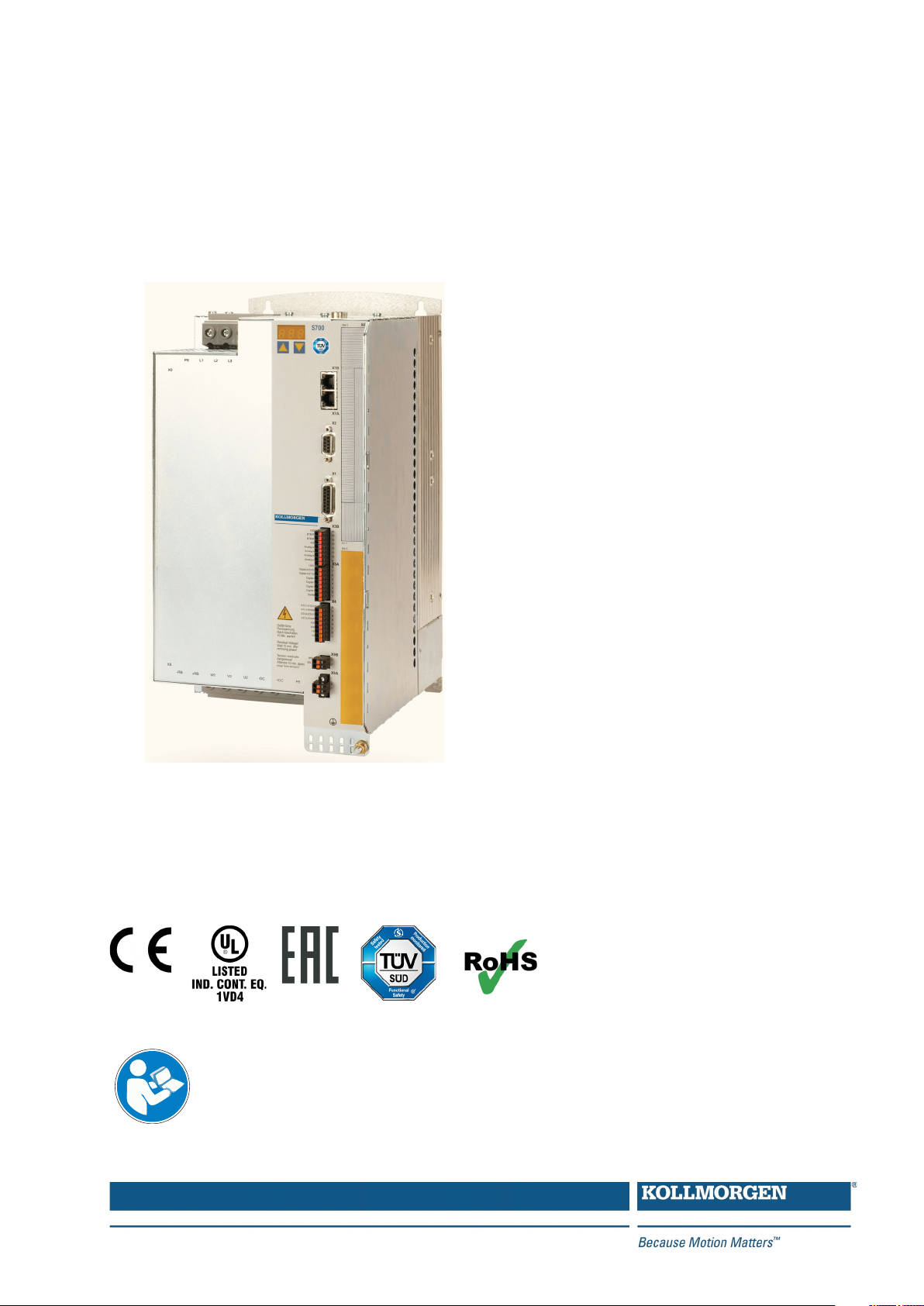
S700
Digital Servo Amplifier S748…S772
Instruction Manual
Edition 11/2018
Translation of the original instruction manual.
Valid for Hardware Revision 02.30
For safe and proper use,
follow these instructions.
Keep them for future reference.
File s748_e.***
Page 2

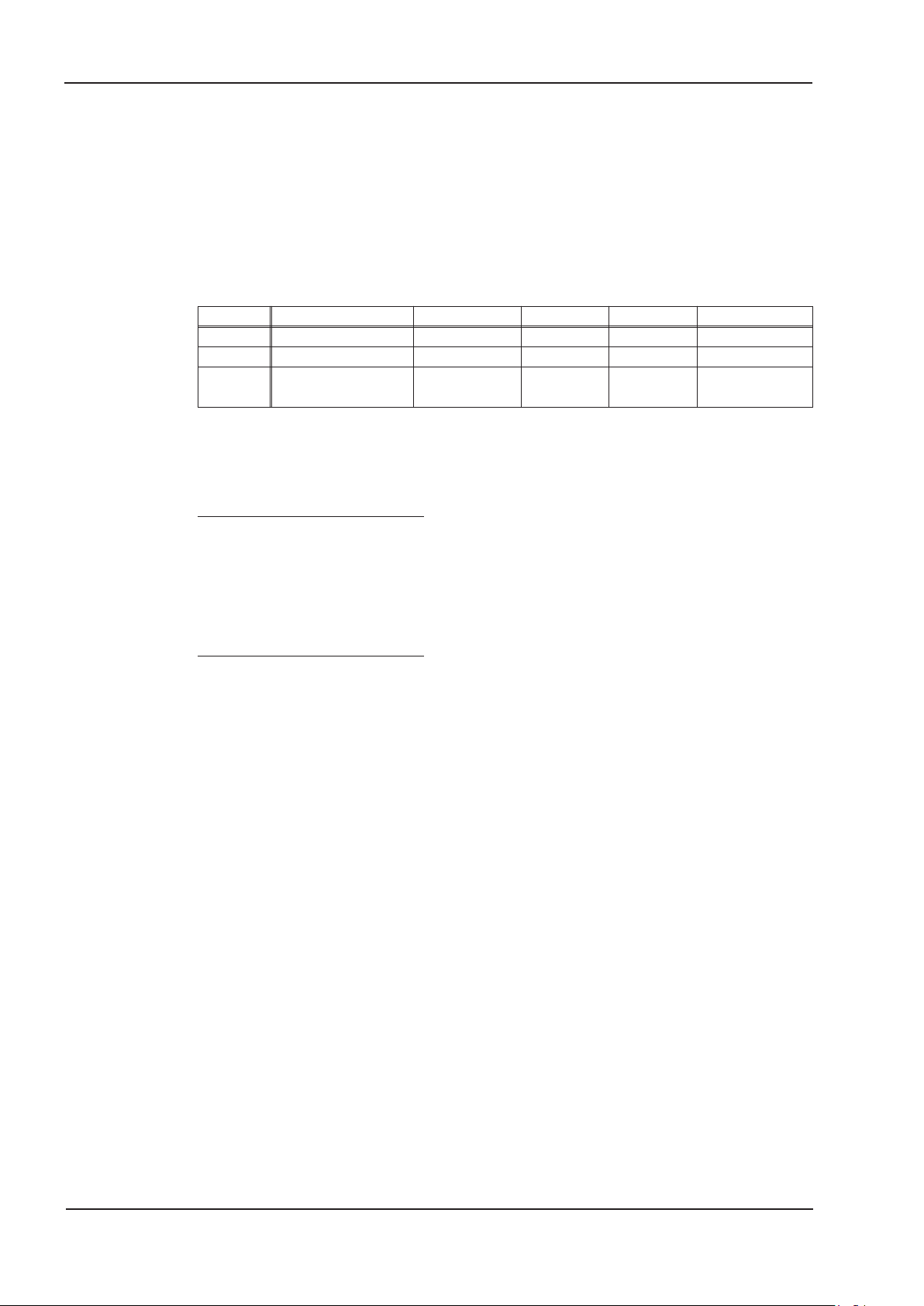
Record of Document Revisions:
Revision Remarks
07/2009 First edition
09/2009 Repair, disposal, standards, directives, GOST-R
11/2009 Safety expansion cards S1/S2, UL listed, FAN option card F2
Part number scheme, safety approved, emergency Stop examples moved to WIKI, S1/S2 cards updated,
09/2011
06/2012 Expansion card FB-2to1 new, Stop/Emergency Stop/Emergency Off updated
07/2013
08/2013 Correction S2-2 (S4) safety card (SLP not possible)
11/2013 Hint automatic restart, fault table, switch off behaviour in case of faults, VBUSBAL=4
05/2014 Warning symbols updated, SSI emulation timing updated, safe to touch voltage 40V->60V
07/2014 Wiring thermo sensor updated (Feedback)
12/2014
02/2015 EAC certification, nameplate with EAC sign, coldplate version new
12/2015
02/2017
11/2018
new DriveGUI icon, bridge DGND-GND (dig-I/O) changed, notes holding brake, climatic classes, WIKI links
updated, 2CAN module, company name&address, encoder emulation X1, BiSS-C
Feedback - ENCVON note, FBTYPE 34, CE declaration of conformity, formal improvements, BiSS C
Renishaw, according to IEC 82079, safety cards S1/S2 replaced by S3/S4, diagram "Behavior in the event
of an error" updated.
Note drive feedback restrictions with Safety Cards, CE declaration of conformity removed, GOST-R
removed, Safety certificates removed, HWR, export classification
Functional Safety certification expanded, safety chapter typo: discharge time corrected, fax form removed,
use as directed extended, safe to touch voltage 60V->50V, fuse FB1/2 to 100A, LVD 2014/35/EC, EMCD
2014/30/EC
X6 Pin 1 corrected (no 5V output), warning notes, handling separate chapter, single cable connection new,
SFD3/Hiperface DSL new
Connector X1 corrected (male->female), HR table updated, layout of the warning notes updated, user
expertise updated, new readers note on cover page, Wiki replaced by KDN
Hardware Revision (HR)
Hardware Revi-
sion
01.01 5.00 - 5.17 AL-3A225 Starting version (STO and Safety pending)
02.10 5.18 - 5.99 AL-3A225 STO and Safety Cards S1/S2 approved
02.20 5.18_ND0 - 5.99_ND0 - New data structure
02.30
WINDOWS is a registered trademark of Microsoft Corporation
HIPERFACE is a registered trademark of Max Stegmann GmbH
SERCOS is a registered trademark of sercos
EnDat is a registered trademark of Dr.Johannes Heidenhain GmbH
EtherCAT is a registered trademark and patented technology, licensed by Beckhoff Automation GmbH
Technical changes which improve the performance of the device may be made without prior notice!
All rights reserved. No part of this work may be reproduced in any form (by photocopying, microfilm or any other method)
or stored, processed, copied or distributed by electronic means without the written permission of Kollmorgen Europe
GmbH.
usable
Firmware
Revision
³ 6.00_ND0
Export
Classification
- SFD3/DSL support
®
international e.V.
Remarks
Page 3

Kollmorgen 11/2018 Contents
Page
1 General
1.1 About this manual................................................................7
1.2 Hints for the online edition (PDF format) ..............................................7
1.3 Symbols used ...................................................................8
1.4 Standards used..................................................................9
1.5 Abbreviations used ..............................................................10
2 Safety
2.1 You should pay attention to this ....................................................11
2.2 Use as directed.................................................................13
2.3 Prohibited use..................................................................14
2.4 Warning notes placed on the product................................................14
3 Handling
3.1 Transport .....................................................................15
3.2 Packaging.....................................................................15
3.3 Storage .......................................................................15
3.4 Decommissioning ...............................................................16
3.5 Maintenance and cleaning ........................................................16
3.6 Disassemble ...................................................................16
3.7 Repair ........................................................................17
3.8 Disposal ......................................................................17
4 Approvals
4.1 Conformance with UL............................................................18
4.2 CE conformance................................................................19
4.2.1 European Directives and Standards for the machine builder .........................19
4.2.2 Safety Conformance (STO) according to Machine Directive .........................20
4.3 EAC Conformance ..............................................................20
5 Package
5.1 Package supplied ...............................................................21
5.2 Nameplate ....................................................................21
5.3 Part number scheme ............................................................22
6 Technical description
6.1 The S748/772 family of digital servo amplifiers ........................................23
6.2 Technical data .................................................................26
6.2.1 Rated Data ...............................................................26
6.2.2 Inputs / outputs, aux. voltage supply............................................27
6.2.3 Connectors/Terminals .......................................................27
6.2.4 Recommended tightening torques .............................................27
6.2.5 Fusing ...................................................................28
6.2.6 Ambient conditions, ventilation, mounting position .................................28
6.2.7 Conductor cross-sections ....................................................29
6.3 LED display....................................................................29
6.4 Grounding system ..............................................................29
6.5 Motor holding brake .............................................................30
6.6 Dynamic Braking ...............................................................31
6.7 Switch-on and switch-off behavior ..................................................32
6.7.1 Behavior in standard operation ................................................33
6.7.2 Behavior in the event of an error (with standard setting) ............................34
6.8 Stop-, Emergency Stop-, Emergency Off Function to IEC 60204 ..........................35
6.8.1 Stop .....................................................................35
6.8.2 Emergency Stop ...........................................................36
6.8.3 Emergency Off.............................................................36
S748-S772 Instructions Manual 3
Page 4

Contents 11/2018 Kollmorgen
Page
6.9 Safety Function STO ............................................................37
6.9.1 Safety characteristic data ....................................................37
6.9.2 Safety notes...............................................................38
6.9.3 Use as directed STO ........................................................39
6.9.4 Prohibited Use STO ........................................................39
6.9.5 Enlosure .................................................................39
6.9.6 Wiring ...................................................................39
6.9.7 Technical Data ............................................................39
6.9.8 Technical data and pinning ...................................................40
6.9.9 Functional description .......................................................41
6.9.10 Functional test .............................................................46
6.10 Shock-hazard protection..........................................................48
6.10.1 Leakage current ...........................................................48
6.10.2 Residual current protective device (RCD)........................................48
6.10.3 Isolating transformers .......................................................48
7 Mechanical Installation
7.1 Important notes.................................................................49
7.2 Guide to mechanical installation....................................................49
7.3 Dimensions....................................................................50
7.3.1 Device with heat sink........................................................50
7.3.2 Device with Coldplate .......................................................51
7.4 Assembly .....................................................................52
7.4.1 Mounting the shielding plate ..................................................52
7.4.2 Backplane mounting - devices with heat sink .....................................53
7.4.3 Backplane mounting - devices with Coldplate ....................................54
8 Electrical installation
8.1 Important notes.................................................................55
8.2 Guide to electrical installation......................................................56
8.3 Wiring ........................................................................57
8.3.1 Shielding connection to the front panel..........................................58
8.3.2 Technical data for connecting cables ...........................................59
8.4 Components of a servo system ....................................................60
8.5 Block diagram..................................................................61
8.6 Connector assignments ..........................................................62
8.7 Connection Diagram (Overview) ...................................................63
8.8 Electrical supply ................................................................64
8.8.1 Connection to various mains supply networks ....................................64
8.8.2 Mains supply connection (X0) .................................................65
8.8.3 24V auxiliary supply (X4).....................................................65
8.9 DC bus link (X8) ................................................................66
8.9.1 DC Bus topology ...........................................................67
8.9.2 External brake resistor (X8) ..................................................67
8.9.3 Capacitor Module KCM (X8) ..................................................68
8.10 Motor connection ...............................................................69
8.10.1 Motor Power Connection (X8).................................................69
8.10.2 Motor holding brake (X8, X9B) ................................................70
8.11 Feedback Systems ..............................................................70
8.12 Primary and secondary feedback types ..............................................71
8.12.1 SFD3 (X1), single cable connection ............................................72
8.12.2 HIPERFACE DSL (X1), single cable connection ..................................73
8.12.3 Resolver (X2) .............................................................74
8.12.4 Sine Encoder with BiSS analog (X1)............................................75
8.12.5 Sine Encoder with BiSS digital (X1) ............................................76
8.12.6 Sine Encoder with EnDat 2.1 (X1) .............................................77
8.12.7 Encoder with EnDat 2.2 (X1)..................................................78
8.12.8 Sine Encoder with HIPERFACE (X1) ...........................................79
8.12.9 Sine Encoder with SSI (X1)...................................................80
4 S748-S772 Instructions Manual
Page 5

Kollmorgen 11/2018 Contents
Page
8.12.10 Sine Encoder without data channel (X1).........................................81
8.12.11 Sine Encoder with Hall (X1) ..................................................82
8.12.12 ROD (AquadB) 5V, 1.5MHz (X1) ..............................................83
8.12.13 ROD (AquadB) 5V, 350kHz (X1)...............................................84
8.12.14 ROD (AquadB) 5V, 350kHz with Hall (X1) .......................................85
8.12.15 ROD (AquadB) 24V (X3).....................................................86
8.12.16 ROD (AquadB) 24V with Hall (X3, X1) ..........................................87
8.12.17 SSI Encoder (X1) ..........................................................88
8.12.18 Hall sensors (X1)...........................................................89
8.13 Electronic Gearing, Master-slave operation ...........................................90
8.13.1 Signal source..............................................................90
8.13.2 Connection to stepper motor controllers (step and direction) .........................91
8.13.3 Master-slave operation ......................................................92
8.14 Encoder Emulation, position output .................................................93
8.14.1 Incremental encoder output - A quad B (X1) .....................................93
8.14.2 SSI encoder output (X1) .....................................................94
8.15 Digital and analog inputs and outputs ...............................................95
8.15.1 Analog Inputs (X3B) ........................................................95
8.15.2 Digital Inputs (X3A, X3B, X4) .................................................96
8.15.3 Digital Outputs (X3A, X3B, X4) ................................................98
8.16 RS232 interface, PC connection (X6) ..............................................100
8.17 CANopen interface (X6) .........................................................101
8.18 EtherNET interface (X7) .........................................................102
8.19 Memory Card .................................................................103
9Setup
9.1 Important notes................................................................105
9.2 Setup software ................................................................106
9.2.1 Use as directed ...........................................................106
9.2.2 Software description .......................................................106
9.2.3 Hardware requirements, operating systems .....................................107
9.2.4 Installation under WINDOWS ................................................107
9.3 Quickstart ....................................................................108
9.3.1 Preparation ..............................................................108
9.3.2 Connect .................................................................110
9.3.3 Important Screen Elements..................................................111
9.3.4 Setup Wizard.............................................................112
9.3.5 Motion Service (Jog Mode) ..................................................115
9.3.6 More Setup Screens .......................................................116
9.4 Multi axis system ..............................................................117
9.5 Keypad operation / LED display ...................................................117
9.5.1 Keypad operation .........................................................118
9.5.2 Status display ............................................................118
9.5.3 Standard menu ...........................................................118
9.5.4 Advanced menu ..........................................................119
9.6 Error messages ...............................................................120
9.7 Warning messages.............................................................121
9.8 Trouble Shooting ..............................................................122
S748-S772 Instructions Manual 5
Page 6

Contents 11/2018 Kollmorgen
Page
10 Expansions
10.1 Expansion cards for slot 1 .......................................................123
10.1.1 Guide to installation of expansion cards in slot 1 .................................123
10.1.2 Expansion card -I/O-14/08- ..................................................124
10.1.3 Expansion card -PROFIBUS- ................................................127
10.1.4 Expansion card -SERCOS-..................................................128
10.1.5 Expansion card - DEVICENET - ..............................................130
10.1.6 Expansion card -SYNQNET-.................................................133
10.1.7 Expansion card - FB-2to1 - ..................................................135
10.1.8 Expansion module -2CAN- ..................................................137
10.2 Expansion cards for slot 2 .......................................................139
10.2.1 Guide to installation of expansion cards in slot 2 .................................139
10.2.2 Option "F2", controlled Fan ..................................................139
10.2.3 Expansion card "PosI/O" and "PosI/O-Monitor" ..................................140
10.3 Expansion cards for slot 3 .......................................................149
10.3.1 Guide to installation of expansion cards in slot 3 .................................149
10.3.2 Option "F2", controlled Fan ..................................................149
10.3.3 Expansion cards "PosI/O" & "PosI/O-Monitor" ...................................149
10.3.4 Expansion card "Safety 2-2" (S4) .............................................150
10.3.5 Expansion card "Safety 1-2" (S3) .............................................152
11 Appendix
11.1 Glossary .....................................................................155
11.2 Order codes ..................................................................157
11.2.1 Servo amplifiers...........................................................157
11.2.2 Memory Card.............................................................157
11.2.3 Expansion cards ..........................................................158
11.2.4 Mating connectors .........................................................158
11.3 Index ........................................................................160
6 S748-S772 Instructions Manual
Page 7

Kollmorgen 11/2018 General
1 General
1.1 About this manual
This manual describes the S748/772 series of digital servo amplifiers (standard version:
48A ...72A rated current). S701 to S724 amplifiers are described in an additional product
manual.
A more detailed description of the expansion cards that are currently available and the
digital connection to automation systems can be found, together with our application
notes, in Acrobat-Reader format on the accompanying CD-ROM (system requirements:
WINDOWS, Internet Browser, Acrobat Reader) in different languages.
Technical data and dimensional drawings of accessories such as cables, brake resistors,
mains supplies, etc., can be found in the accessories manual.
This documentation (PDF) can be printed out on any standard commercial printer. A
printed copy of the documentation is available from us at extra cost.
More background information can be found in our "Kollmorgen Developer Network"
kdn.kollmorgen.com
.
1.2 Hints for the online edition (PDF format)
Bookmarks:
Table of contents and index are active bookmarks.
Table of contents and index in the text:
The lines are active cross references. Click on the desired line and the appropriate page
is accessed.
Page/chapter numbers in the text:
Page/chapter numbers with cross references are active. Click at the page/chapter number to reach the indicated target.
S748-S772 Instructions Manual 7
Page 8
General 11/2018 Kollmorgen
DANGER
WARNING
CAUTION
NOTICE
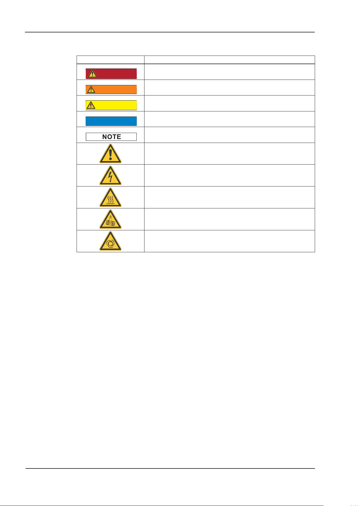
1.3 Symbols used
Symbol Indication
Indicates a hazardous situation which, if not avoided, will result
in death or serious injury.
Indicates a hazardous situation which, if not avoided, could re
sult in death or serious injury.
Indicates a hazardous situation which, if not avoided, could re
sult in minor or moderate injury.
This is not a safety symbol. Indicates situations which, if not
avoided, could result in property damage.
This is not a safety symbol. This symbol indicates important
notes.
Warning of a danger (general). The type of danger is specified
by the warning text next to it.
Warning of danger from electricity and its effects.
Warning of danger from hot surfaces.
-
-
Warning of danger from suspended loads.
Warning of danger from automatic start.
8 S748-S772 Instructions Manual
Page 9

Kollmorgen 11/2018 General
1.4 Standards used
Standard Content
ISO 4762 Hexagon socket head cap screws
ISO 13849 Safety of machinery: Safety-related parts of control systems
ISO 12100 Safety of machinery: Basic concepts, general principles for design
IEC 60085 Electrical insulation - Thermal evaluation and designation Maintenance
IEC 60204 Safety of Machinery: Electrical equipment of machinery
IEC 60364 Low-voltage electrical installations
IEC 60439 Low-Voltage Switchgear and Controlgear Assemblies
IEC 60529 Protection categories by housing (IP Code)
IEC 60664 Insulation coordination for equipment within low-voltage systems
IEC 60721 Classification of environmental conditions
IEC 61000 Electromagnetic compatibility (EMC)
IEC 61131 Programmable controllers
IEC 61491
IEC 61508
IEC 61800 Adjustable speed electrical power drive systems
IEC 62061
IEC 82079 Preparation of instructions for use - Structuring, content and presentation
UL 840
UL 508C UL Standard for Safety Power Conversion Equipment
Electrical equipment of industrial machines – Serial data link for real-time
communications between controls and drives.
Functional safety of electrical/electronic/programmable electronic
safety-related systems
Functional safety of electrical/electronic/programmable electronic
safety-related systems
UL Standard for Safety for Insulation Coordination Including Clearances
and Creepage Distances for Electrical Equipment
IEC International Electrotechnical Commission UL Underwriters Laboratories
ISO International Organization for Standardization
S748-S772 Instructions Manual 9
Page 10

General 11/2018 Kollmorgen
1.5 Abbreviations used
Abbrev. Meaning
AGND Analog ground
xAF Fuse, x Amps, fast
xAM Fuse, x Amps, medium
xAT Fuse, x Amps, slow
BTB/RTO Ready to operate
CAN Fieldbus (CANopen)
CE Communité Europeenne
CLK Clock signal
COM Serial interface for a Personal Computer
DGND Digital ground (for 24V and digital I/O)
Disk Magnetic storage (diskette, hard disk)
EEPROM Electrically erasable programmable memory
EMC Electromagnetic compatibility
F-SMA Fiber Optic Cable connector according to IEC 60874-2
IGBT Insulated-gate bipolar transistor
KDN Kollmorgen Developer Network
LED Light-emitting diode
MB Megabyte
NI Zero pulse
PC Personal computer
PL Performance Level
PLC Programmable logic control
PWM Pulse-width modulation
RAM Volatile memory
R
Brake/RB
RBext External brake resistor
RBint Internal brake resistor
RES Resolver
ROD Digital encoder (A quad B)
SDI Safe direction
SIL Safety Integrity Level
SIL CL Safety Integrity Level Claim Limit
SLI Safe limited increments
SLP Safe limited position
SLS Safe limited speed
SOS Safe operating stop
SS1 Safe stop 1
SS2 Safe stop 2
SSI Synchronous serial interface
SSR Safe speed range
STO Safe torque off (former AS)
V AC Alternating voltage
V DC DC voltage
VDE Society of German Electrical Technicians
Brake resistor (sometimes called "regen resistor")
10 S748-S772 Instructions Manual
Page 11

Kollmorgen 11/2018 Safety
2 Safety
2.1 You should pay attention to this
Read the documentation!
Read the available documentation before installation and commissioning. Improper han
dling of the servo amplifiers can cause harm to people or damage to property. The opera
tor must therefore ensure that all persons entrusted to work on the S748/772 have read
and understood the manual and that the safety notices in this manual are observed.
Perform a risk assessment!
The manufacturer of the machine must generate a risk assessment for the machine, and
take appropriate measures to ensure that unforeseen movements cannot cause injury or
damage to any person or property. Additional requirements on specialist staff may also
result from the risk assessment.
S
pecialist staff required!
Only properly qualified personnel are permitted to perform such tasks as transport, instal
lation and setup. Qualified specialist staff are persons with expertise in transport, installa
tion, assembly, commissioning and operation of electrotechnical equipment.
l
Transport, storage, unpacking: only by personnel with knowledge of handling electro
statically sensitive components.
l
Mechanical installation: only by qualified personnel with mechanical expertise.
l
Electrical installation: only by qualified personnel with electrotechnical expertise.
l
Basic tests / setup: only by qualified personnel with expertise in electrical engineering
and drive technology.
The qualified personnel must know and observe ISO 12100 / IEC 60364 / IEC 60664 and
national accident prevention regulations.
-
-
-
-
Check the Hardware Revision!
Check the Hardware Revision Number of the product (see product label). This revision
number must match the Hardware Revision Number on the cover page of the manual. If
the numbers do not match up, visit the European File Archive
(http://www.wiki-kollmorgen.eu
). The 'Download' section contains the various manual ver
sions based on the hardware version number.
Pay attention to the technical data!
Adhere to the technical data and the specifications on connection conditions (rating plate
and documentation). If permissible voltage values or current values are exceeded, the
servo amplifiers can be damaged. Unsuitable motor or wrong wiring will damage the sys
tem components. Check the combination of drive and motor. Compare the rated voltage
and current of the units.
Observe electrostatically sensitive components!
The servo amplifiers contain electrostatically sensitive components which may be dam
aged by incorrect handling. Discharge your body before touching the servo amplifier.
Avoid contact with highly insulating materials (artificial fabrics, plastic film etc.). Place the
servo amplifier on a conductive surface.
-
-
S748-S772 Instructions Manual 11
Page 12
Safety 11/2018 Kollmorgen
Automatic restart
The drive might restart automatically after power on, voltage dip or interruption of the sup
ply voltage, depending on the parameter setting. Risk of death or serious injury for
humans working in the machine. If the parameter AENA
sign to the machine (Warning: Automatic Restart at Power On) and ensure, that power on
is not possible, while humans are in a dangerous zone of the machine. In case of using
an undervoltage protection device, you must observe EN 60204-1:2006 chapter 7.5.
Hot surface!
The surfaces of the servo amplifiers can be hot in operation. Risk of minor burns!
The surface temperature can exceed 80°C. Measure the temperature, and wait until the
motor has cooled down below 40°C before touching it.
Earthing!
It is vital that you ensure that the servo amplifiers are safely earthed to the PE (protective
earth) busbar in the switch cabinet. Risk of electric shock. Without low-resistance
earthing no personal protection can be guaranteed and there is a risk of death from elec
tric shock.
Leakage Current!
Since the leakage current to PE is more than 3.5 mA, in compliance with IEC61800-5-1
the PE connection must either be doubled or a connecting cable with a cross-section >10
mm² must be used. Deviating measures according to regional standards might be possible.
is set to 1, then place a warning
-
-
High voltages!
The equipment produces high electric voltages up to 900V. During operation, servo
amplifiers may have uncovered live sections, according to their level of enclosure protection. Capacitors can have dangerous voltages present up to ten minutes after switching
off the supply power. There is a risk of death or severe injury from touching exposed contacts. Keep all covers and cabinet doors closed during operation. Touching the equipment is allowed during installation and commissioning for properly qualified persons only.
There is a danger of electrical arcing when disconnecting connectors, because capacitors
can still have dangerous voltages present up to ten minutes after switching off the supply
power. Risk of burns and blinding. Wait at least ten minutes after disconnecting the servo
amplifiers from the main supply power before touching potentially live sections of the
equipment (such as contacts) or removing any connections. Always measure the voltage
in the DC bus link and wait until the voltage is below 50V before handling components.
Reinforced Insulation!
Thermal sensors, motor holding brakes and feedback systems built into the connected
motor must have reinforced insulation (according to IEC61800-5-1) against system com
ponents with power voltage, according to the required application test voltage. All
Kollmorgen components meet these requirements.
Never modify the servo amplifiers!
It is not allowed to modify the servo amplifiers without permission by the manufacturer.
Opening the housing causes loss of warranty and all certificates become unvalid.
Warning signs are added to the device housing. If these signs are damaged, they must
be replaced immediately.
-
12 S748-S772 Instructions Manual
Page 13

Kollmorgen 11/2018 Safety
2.2 Use as directed
Servo amplifiers are safety components that are built into electrical plant or machines,
and can only be operated as integral components of such plant or machines.
The manufacturer of the machine must generate a risk assessment for the machine, and
take appropriate measures to ensure that unforeseen movements cannot cause injury or
damage to any person or property.
If the servo amplifiers are used in residential areas, in business/commercial areas, or in
small industrial operations, then additional filter measures must be implemented by the
user.
Cabinet and Wiring
The servo amplifiers must only be operated in a closed control cabinet, taking into
account the ambient conditions defined on page 28. Ventilation or cooling may be neces
sary to keep the temperature within the cabinet below 40°C.
Use only copper conductors for wiring. The conductor cross-sections can be derived from
the standard IEC 60204 (for AWG: NEC Table 310-16, 60°C or 75°C column).
Power supply
Servo amplifiers in the S748/772 series (overvoltage category III acc. to EN 61800-5-1)
can be supplied from 3-phase grounded (earthed) industrial supply networks (TN-system,
TT-system with grounded neutral point, no more than 42kA symmetrical rated current at
208V
(with an isolating transformer) is described on page 64. In case of mains voltage asymmetry >3% a mains choke must be used.
, 230V, 240V, 400V or 480V
-10%
+10%
). Connection to other types of supply networks
-
Periodic overvoltages between phases (L1, L2, L3) and the housing of the servo
amplifier must not exceed 1000V crest. In accordance with IEC 61800, voltage spikes (<
50µs) between phases must not exceed 1000V. Voltage spikes (< 50µs) between a
phase and the housing must not exceed 2000V.
For the cases of DC input power for single and group installations
S700 has not been evaluated by Kollmorgen, UL, or TÜV for replacing AC mains input
with DC input - for either single or group installations.
DC installations must be reviewed and evaluated by the user for branch circuit protec
tion*, wire size, wire voltage rating, fuse protection, system dielectric requirements,
overvoltage and input** current rating.
In case of DC supplied drives the built-in EMC filter will not work. The user is responsible
to keep the conducted emissions and the immunity of the drive within the required noise
levels.
*Special care must be taken in branch circuit design with mixed rating drives to avoid the
smaller drives becoming the effective ‘fuse’ rather than the circuit protective fuse.
**The power supply system design must ensure inrush current protection by limiting input
current during power up. DC supply polarity must be properly wired. Improper polarity of
DC power will damage the drive and void warranty.
-
S748-S772 Instructions Manual 13
Page 14
Safety 11/2018 Kollmorgen
NOTICE
Motors
The S748/772 family of servo amplifiers is exclusively intended for driving suitable
brushless synchronous servomotors, asynchronous motors and DC motors with control of
torque, speed and/or position.
The rated voltage of the motors must be at least as high as the DC bus link voltage
divided by
Functional Safety
Observe the chapter "use as directed" on page 39 when you use the safety function STO.
produced by the servo amplifier (U
2
nMotor
³ UDC/
).
2
To achieve PL e or SIL CL3, the safe switching of the pulse inhibitor must be tested peri
odically by analyzing the feedback signal from the safety control (ð p. 47).
Observe the user documentation for safety cards S1-2(S3) / S2-2(S4) when you use a
safety expansion card.
2.3 Prohibited use
Other use than described in chapter 2.2 is not intended and can lead to damage of per
sons, equipment or things.
The use of the servo amplifier in the following environments is prohibited:
- potentially explosive areas
- environments with corrosive and/or electrically conductive acids, alkaline solutions,
oils, vapors, dusts
- directly on non-grounded supply networks or on asymmetrically grounded supplies
with a voltage >240V.
- on ships or off-shore applications
Commissioning the servo amplifier is prohibited if the machine in which it was installed,
- does not meet the requirements of the EC Machinery Directive
- does not comply with the EMC Directive or with the Low Voltage Directive
- does not comply with any national directives
The control of holding brakes by the S748/772 alone may not be used in applications,
where functional safety is to be ensured with the brake.
-
-
2.4 Warning notes placed on the product
Residual Voltage
Wait 10 minutes
after removing
power.
If these signs are damaged, they must be replaced immediately.
14 S748-S772 Instructions Manual
Page 15

Kollmorgen 11/2018 Handling
NOTICE
3 Handling
3.1 Transport
l
Transport by qualified personnel in the manufacturer’s original recyclable packaging
l
Avoid shocks while transporting
l
Transport temperature: -25 to +70°C, max. rate of change 20K / hour,
class 2K3 acc. to EN61800-2, EN 60721-3-1
l
Transport humidity: max. 95% relative humidity, no condensation,
class 2K3 acc. to EN61800-2, EN 60721-3-1
l
If the packaging is damaged, check the unit for visible damage. In such an event, in
form the shipper and the manufacturer.
The servo amplifiers contain electrostatically sensitive components, that can be damaged
by incorrect handling. Discharge yourself before touching the servo amplifier. Avoid con
tact with highly insulating materials, such as artificial fabrics and plastic films. Place the
servo amplifier on a conductive surface.
3.2 Packaging
-
-
l
Recyclable cardboard with inserts
l
Dimensions: 390 x 600 x 400 mm
l
Labeling: name plate on outside of box
3.3 Storage
l
Storage only in the manufacturer’s original recyclable packaging
l
Max. stacking height: 3 cartons
l
Storage temperature: -25 to +55°C, max. rate of change 20K / hour,
l
Storage humidity: 5 … 95% relative humidity, no condensation,
l
Storage duration:
Less than 1 year: without restriction.
More than 1 year: capacitors must be re-formed before setting up and operating the
servo amplifier. To do this, remove all electrical connections and apply single-phase
230V AC for about 30 minutes to the terminals L1 / L2.
class 1K4 acc. to EN61800-2, EN 60721-3-1
class 1K3 acc. to EN61800-2, EN 60721-3-1
S748-S772 Instructions Manual 15
Page 16

Handling 11/2018 Kollmorgen
NOTICE
NOTICE
NOTICE
3.4 Decommissioning
Only professional staff who are qualified in electrical engineering are allowed to decom
mission parts of the drive system.
DANGER: Lethal voltages! There is a danger of serious personal injury or death by
electrical shock or electrical arcing.
l
Switch off the main switch of the switchgear cabinet.
l
Secure the system against restarting.
l
Block the main switch.
l
Wait at least 10 minutes after disconnecting.
3.5 Maintenance and cleaning
The device does not require maintenance. Opening the device voids the warranty. The
inside of the unit can only be cleaned by the manufacturer
Do not immerse or spray the device. Avoid that liquid enters the device.
To clean the device exterior:
1. Decommission the device (see chapter 3.4).
2. Casing: Clean with isopropanol or similar cleaning solution.
CAUTION: Highly Flammable! Risk of injury by explosion and fire.
- Observe the safety notes given on the cleaning liquid package.
- Wait at least 30 minutes after cleaning before putting the device back into
operation.
3. Protective grill on fan: Clean with a dry brush.
-
3.6 Disassemble
Only professional staff who are qualified in electrical engineering are allowed to disassemble parts of the drive system.
1. Decommission the device (see chapter 3.4).
2. Check temperature.
CAUTION: High Temperature! Risk of minor burns.
During operation, the heat sink of the drive may reach temperatures above
80 °C (176 °F). Before touching the device, check the temperature and wait until it
has cooled below 40 °C (104 °F).
3. Remove the connectors. Disconnect the potential earth connection last.
4. Demount: loosen the fastening screws. Remove the device.
16 S748-S772 Instructions Manual
Page 17

Kollmorgen 11/2018 Handling
NOTICE
NOTICE
3.7 Repair
Only professional staff who are qualified in electrical engineering are allowed to exchange
parts of the drive system.
CAUTION: Automatic Start! During replacement work a combination of hazards and
multiple episodes may occur.
- Work on the electrical installation may only be performed by trained and qualified
personnel, in compliance with the regulations for safety at work, and only with
use of prescribed personal safety equipment.
Exchange of servo amplifier
Only the manufacturer can repair the device. Opening the device voids the warranty.
1. Decommission the device (see chapter 3.4).
2. Demount the device (see chapter 3.6).
3. Contact Kollmorgen and clarify the logistics. Send the device to the address given by
Kollmorgen.
4. Install a new device as described in this manual.
5. Setup the servo amplifier as described in this manual.
Exchange of other drive system parts
3.8
If parts of the drive system ( for example cables) must be replaced, proceed as follows:
1. Decommission the device (see chapter 3.4).
2. Exchange the parts.
3. Check all connections for correct fastening.
4. Setup the servo amplifier as described in this manual.
Disposal
To
dispose the unit properly, contact a certified electronic scrap disposal merchant.
In accordance with the WEEE-2012/19/EC-Guidelines and similar, the manufacturer
accepts returns of old devices and accessories for professional disposal. Transport costs
are the responsibility of the sender.
Decommission the device as described in chapter 3.4 and demount the device as
described in chapter 3.6.
Contact Kollmorgen and clarify the logistics. Send the device to the address given by
Kollmorgen.
S748-S772 Instructions Manual 17
Page 18

Approvals 11/2018 Kollmorgen
4 Approvals
Certificates (CE, functional safety) can be found in the download section of the "File
Archive".
4.1 Conformance with UL
This servo amplifier is listed under UL file number E217428.
UL-certified servo amplifiers (Underwriters Laboratories Inc.) fulfil the relevant U.S. stan
dards (in this case UL 840 and UL 508C).
This standard describes the fulfillment by design of minimum requirements for electrically
operated power conversion equipment, such as frequency converters and servo amplifi
ers, which is intended to eliminate the risk of fire, electric shock, or injury to persons,
being caused by such equipment. The technical conformance with the U.S. standard is
determined by an independent UL inspector through the type testing and regular check
-
ups.
Apart from the notes on installation and safety in the documentation, the customer does
not have to observe any other points in direct connection with the UL-certification of the
equipment.
UL 508C
UL 508C describes the fulfillment by design of minimum requirements for electrically
operated power conversion equipment, such as frequency converters and servo amplifiers, which is intended to eliminate the risk of fire being caused by such equipment.
UL 840
UL 840 describes the fulfillment by design of air and insulation creepage spacings for
electrical equipment and printed circuit boards.
UL Markings
l
Use 60°C or 75°C copper wire only for every model of this section.
l
Tightening torque and wire size for field wiring terminals.
X0 8-2 AWG, TQ Lb In. 40.
X8 8-2 AWG, TQ Lb In. 40.
l
For use in a pollution degree 2 environment only.
l
These devices provide solid state motor overload protection at 130% of full load
current.
l
Integral solid state short circuit protection does not provide branch circuit protection.
Branch circuit protection must be provided in accordance with the National Electrical
Code and any additional local codes.
l
These devices are not provided with motor over-temperature sensing.
l
Suitable for use on a circuit capable of delivering not more than 42kA rms symmetri
cal amperes” for a max. Voltage of 480 Vac.
l
Supply circuit protection:
-
-
Model Fuse class Voltage Rating Max. Fuse and SCC Rating
S7480 RK5, CC, J, T 600V AC 60A / 200kA
S7720 RK5, CC, J, T 600V AC 80A / 200kA
l
For use on a solidly grounded wye source only.
18 S748-S772 Instructions Manual
Page 19

Kollmorgen 11/2018 Approvals
NOTICE
NOTICE
4.2 CE conformance
The servo amplifiers have been tested by an authorized testing laboratory in a defined
configuration, using the system components that are described in this documentation.
Any divergence from the configuration and installation described in this documentation
means that you will be responsible for carrying out new measurements to ensure confor
mance with regulatory requirements.
-
Kollmorgen declares the conformity of the products S748, S772 with the following direc
tives
l
EC Machinery Directive (2006/42/EC)
l
EC EMC Directive (2014/30/EC)
l
EC Low Voltage Directive (2014/35/EC)
The servo amplifier meets the noise immunity requirements to the 2nd environmental cat
egory (industrial environment). For noise emission the amplifier meets the requirement to
a product of the category C2 (motor cable £ 10m). With a motor cable length of 10m or
longer, the servo amplifier meets the requirement to the category C3.
This product can cause high-frequency interferences in non industrial environments. This
can require measures for interference suppression like additional external EMC filters.
4.2.1 European Directives and Standards for the machine builder
Servo amplifiers are safety components that are intended to be incorporated into electrical plant and machines for industrial use. When the servo amplifiers are built into
machines or plant, the amplifier must not be used until it has been established that the
machine or equipment fulfills the requirements of the
l
EC Machinery Directive (2006/42/EC)
l
EC EMC Directive (2014/30/EC)
l
EC Low Voltage Directive (2014/35/EC)
Standards to be applied for conformance with the EC Machinery Directive (2006/42/EC)
IEC 60204-1 (Safety and Electrical Equipment in Machines)
ISO 12100 (Safety of Machines)
-
-
The manufacturer of the machine must generate a risk assessment for the machine, and
must implement appropriate measures to ensure that unforeseen movements cannot
cause injury or damage to any person or property.
The machine/plant manufacturer must check whether other standards or EC Directives
must be applied to the machine/plant.
Standards to be applied for conformance with the EC Low Voltage Directive(2014/35/EC)
IEC 60204-1 (Safety and Electrical Equipment in Machines)
IEC 60439-1 (Low-voltage switchgear and controlgear assemblies)
Standards to be applied for conformance with the EC EMC Directive (2014/30/EC)
IEC 61000-6-1 / 2 (Interference Immunity in Residential & Industrial Areas)
IEC 61000-6-3 / 4 (Interference Generation in Residential & Industrial Areas)
The manufacturer of the machine/plant is responsible for ensuring that it meets the limits
required by the EMC regulations. Advice on the correct installation for EMC can be found
in this documentation.
We only guarantee the conformance of the servo system with the standards cited in this
chapter if the components (motor, cables, chokes etc.) are those supplied by us.
S748-S772 Instructions Manual 19
Page 20
Approvals 11/2018 Kollmorgen
4.2.2 Safety Conformance (STO) according to Machine Directive
The S748/772 servo amplifier offers a two channel STO function (Safe Torque Off). The
function blocks the trigger pulses of the power transistors (pulse inhibitor).
The STO safety concept is certified by the TÜV. The safety circuit concept for realizing
the safety function "Safe Torque Off" in the servo amplifiers S748/772 is suited for
SIL CL3 according to IEC 62061 and PLe according to ISO 13849-1.
The subsystems (servo amplifiers) are totally described for safety technics with the
characteristic data SIL CL, PFH
and TM.
D
Device Operation mode ISO 13849-1 IEC 62061 PFH
[1/h] TM[Year]
D
STO single channel PLd, Cat. 3 SIL CL 2 7,05E-08 20
STO dual channel PLd, Cat. 3 SIL CL 2 7,05E-08 20
STO
dual channel with
periodical testing
PLe, Cat. 4 SIL CL 3 1,38E-09 20
SIL2 / PLd solutions can be implemented with single-channel or dual-channel control with
simple safety switching devices.
A SIL3 / PLe solution requires a safety control that periodically tests the safe switching of
the pulse inhibitor by analyzing the feedback (status) signals.
Expansion card "Safety 2-2" (S4)
This expansion card (Basic version) includes various safety functions for the safe
operation of drive shafts. All functions fulfill the safety requirements SIL CL2 according to
IEC 62061 respectively performance level PLd according to ISO 13849-1. The functional
safety is certified by the TÜV. Safety characteristic data are listed in the Instructions Manual of the expansion card.
Expansion card "Safety 1-2" (S3)
This expansion card (full version) includes several safety functions. All functions fulfill the
safety requirements SIL CL3 acc. to IEC 62061 respectively performance level PLe acc.
to ISO 13849-1. The functional safety is certified by the TÜV. Safety characteristic data
are listed in the Instructions Manual of the expansion card.
4.3 EAC Conformance
EAC is the abbreviation for Eurasian Conformity. The mark is used in the states of the
Eurasian Customs Union (Russia, Belarus, Kazakhstan) similar to the European CE
mark.
Kollmorgen declares, that the S748/772 has passed all required conformity procedures in
a member state of the Eurasian Customs Union, and that the S748/772 meets all techni
-
cal requirements requested in the member states of the Eurasian Customs Union:
l
Low voltage (TP TC 020/2011)
l
EMC (TP TC 004/2011)
Contact in Russia:
Intelisys LLC. , Bakuninskaya Str. d 14, Building 1, RU-105005 Moskau
20 S748-S772 Instructions Manual
Page 21
Kollmorgen 11/2018 Package
Typenbezeichnung
Spannungsversorgung
Model Number
Power Supply
Ser. Nr
Nennstrom
Ser. No.
Nom. Current
Bemerkung Comment
Umgebungstemp.
Surrounding temp.
Hardware
Revision
Schutzart
Encl.Rating
Kollmorgen Europe GmbH
Pempelfurtstraße 1
D-40880 Ratingen
www.kollmorgen.com
E217428
1VD4
LISTED
IND. CONT. EQ.
U
L
®
RoHS
conform
5 Package
5.1 Package supplied
When an amplifier from the S748/772 series is ordered (order numbers ðp.157), the fol
lowing is supplied:
— Servo amplifier S748/772, shielding plate, shield clamps
— Safety Guide S700 (printed)
— Online documentation and setup software DRIVEGUI.EXE on CD-ROM
— Mating connectors X3A, X3B, X4, X9A, X9B
The mating SubD connectors are not part of the package!
Accessories :
— Motor cable as a cut-off length
— Feedback cable (prefabricated)
or both feedback connectors separately, with the feedback cable as a cut-off length
— External brake resistor BAR(U)
— Communication cable to the PC (ð p.100) for setting parameters from a PC
— Power cable, control cables, fieldbus cables (as cut-off lengths)
— Mains choke if mains voltage is more than 3% asymmetrical
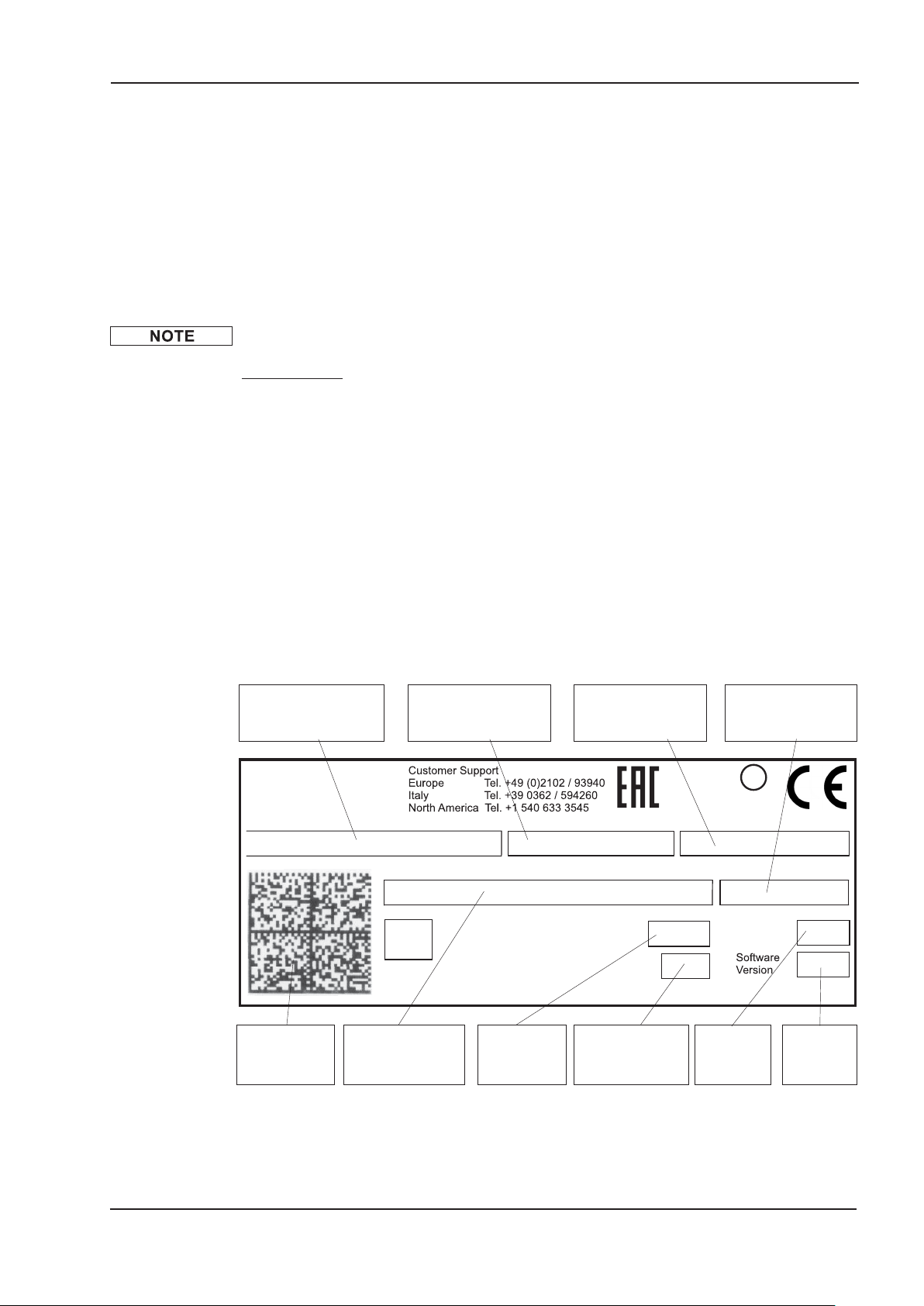
5.2 Nameplate
The nameplate is attached to the side of the servo amplifier.
The information described below is printed in the individual fields.
Picture similar to the original nameplate.
-
(must be ordered separately, if required; description see accessories
manual)
Servo amplifier type
2D bar code
Electrical supply
Installed load
Enclosure
Rating
CommentsSerial number
max.
surrounding
temperature
Output current
in cont. operation
Hardware
Revision
Software
Version
S748-S772 Instructions Manual 21
Page 22
Package 11/2018 Kollmorgen
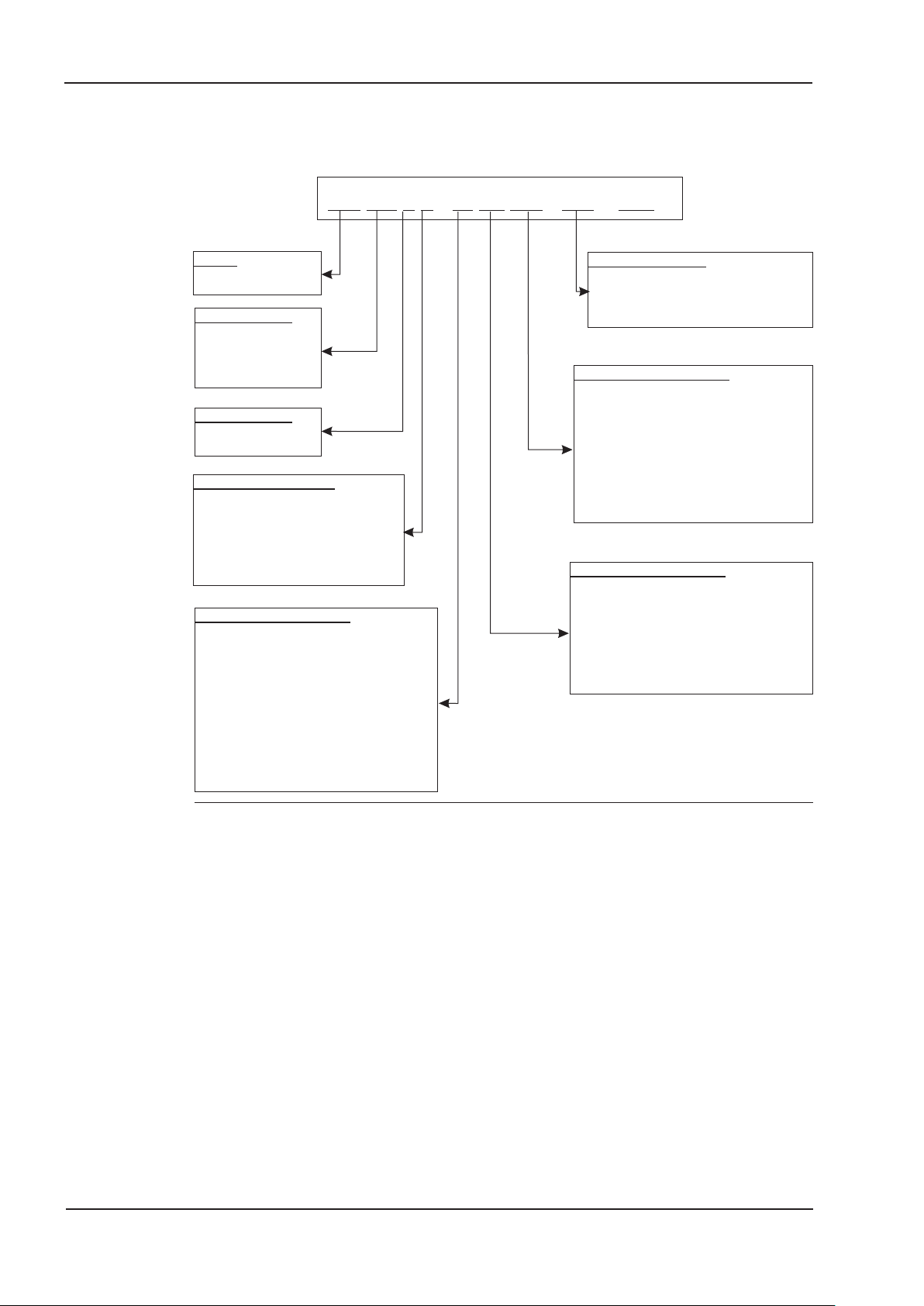
5.3 Part number scheme
The part number is identical with the order code.
S7720 2 -EIF2 PM -NA1- 000
Family
S7 S700
Current Rating
48 48 Arms
72 72 Arms
Voltage Rating
0 208...480V
electr./mech. Options
2 Standard
F Coated PCBs
S748 only:
C Coldplate
A Coldplate + coated PCBs
Expansion Cards Slot 1
NA no expansion card in Slot 1,
EtherCAT&CANopen onboard
2C Module 2CAN mounted
DN DEVICENET
PB PROFIBUS
SE SERCOS II
SN SYNQNET
EI I/O Extension
FB FB-2to1 at X1
4
4
2
Firmware Options
NA no option
(EtherCAT&CANopen)
Expansion Cards Slot 3
NA no expansion card in slot 3,
EtherCAT&CANopen onboard
F2 Fan controller
PM PosI/O
PA PosI/O-Monitor
3
Safety card S1-2, SIL 3
S3
3
Safety card S2-2, SIL 2
S4
Expansion Cards Slot 2
NA no expansion card in Slot 2,
EtherCAT&CANopen onboard
F2 Fan controller
PM PosI/O
PA PosI/O-Monitor
1 is void with standard
2 is void with standard, additional coding defines customer specific specials.
3 described in separate documentation
4 not with expansion cards.
.
Example: S77202-EIF2PM-NA-000
S7 S700 series
72 72A rated current
0 Supply voltage 208...480V
2 no electrical/mechanical option
EI I/O Extension card in Slot 1
F2 Fan controller in Slot 2
PM PosI/O expansion card in Slot 3
NA Standard Firmware (EtherCAT & CANopen onboard)
000 no customer specific specials
22 S748-S772 Instructions Manual
Page 23

Kollmorgen 11/2018 Technical description
6 Technical description
6.1 The S748/772 family of digital servo amplifiers
Standard version
l
Large supply voltage range: 3 x 208V
… 3 x 480V
-10%
(with mains voltage below 300V set parameters NONBTB=3 and VBUSBAL=1.)
l
CANopen onboard
l
EtherCAT onboard
l
RS232 and 24V pulse direction interface onboard
l
Resolver-, Encoder-, AquadB Encoder-, ComCoder-evaluation onboard
l
Position controller onboard
l
STO (Safe Torque Off) onboard (up to SIL CL3, PLe)
l
3 frontside slots for expansion cards
l
Memory Card slot onboard
l
Synchronous servomotors, linear motors, asynchronous motors, and DC motors can
be used
+ 10%
Power section
l
Directly on grounded 3-phase supply, 208V
-10%
… 480V
(with mains voltage below 300V set parameters NONBTB=3 and VBUSBAL=1.)
l
TN-network or TT-network with grounded neutral point, 42kA max. symmetrical cur-
+10%
, 50/60 Hz
rent rating, connection to other supply types only via isolating transformer, ðp.64
l
Overvoltage category III acc. to EN 61800-5-1
l
B6 bridge rectifier, integral supply filter and soft-start circuit
l
Single-phase supply operation possible (e.g. for setup)
l
Fusing (e.g. fusible cutout) to be provided by the user
l
Shielding All shielding connections are made directly on the amplifier
l
Output stage IGBT module with floating current measurement
l
Brake circuit with dynamic distribution of the generated power between
several amplifiers on the same DC bus link circuit.
External brake resistors if required.
l
DC bus link voltage 260...900 V DC, can be connected in parallel.
l
Interference suppression filters are integrated for the electrical supply feed and the
24V auxiliary supply voltage (with motor cable £ 10m for C2 as per IEC 61800-3, with
motor cable < 10m for C3 as per IEC 61800-3).
S748-S772 Instructions Manual 23
Page 24

Technical description 11/2018 Kollmorgen
Integrated safety
l
Appropriate insulation/creepage distances and electrical isolation ensure safe electri
cal separation, as per IEC 61800-5-1, between the power input / motor connections
and the signal electronics.
l
Soft-start, overvoltage detection, short-circuit protection, phase-failure monitoring.
l
Temperature monitoring of the servo amplifier and motor (if our motors and prefabri
cated cables are used).
l
Safe stop (SIL CL3 according to IEC 62061, PLe according to ISO 13849-1) ð p. 37.
l
Slot for optionalsafety card with more safety functions for the safe drive operation,
ð p. 150
Auxiliary supply voltage 24V DC
l
Electrically isolated, internal fusing, from an external 24V DC power supply unit.
l
Separate 24V supply input for internal electronic supply
l
Separate 24V supply input for motor holding brake supply
l
Separate 24V supply input for digital outputs
-
-
Operation and parameter setting
l
With our user-friendly setup software DRIVEGUI.EXE, for setup via the serial interface of a PC.
l
If no PC is available: direct operation by two keys on the servo amplifier and a
3-character LED display.
l
Fully programmable via RS232 interface.
l
Read/write access to parameter records and firmware via memory card.
Completely digital control
l
Digital current controller (space vector, pulse-width modulation, 62.5 µs)
l
Adjustable digital speed controller (62.5 µs)
l
Integrated position controller, with adaptation possibilities for all applications (250 µs,
optionally 125µs)
l
Integrated 24V step/direction interface for connecting a servomotor to a stepper con
troller
Inputs/Outputs
l
2 programmable analog inputs ð p. 95
l
4 programmable digital inputs ð p. 96
l
2 programmable digital inputs/outputs (direction selectable) ð p. 98
l
programmable logical combinations of digital signals
l
1 input Enable ð p. 78
l
2 inputs STO Enable ð p. 97
l
2 outputs STO Status ð p. 99
-
24 S748-S772 Instructions Manual
Page 25

Kollmorgen 11/2018 Technical description
Expansions
Slot 1
Expansion cards in slot 1 can be combined with F2 Option in slot 2. More combinations of
slot 1 and slot 2 expansion cards are not possible.
l
I/O-14/08 expansion card, ð p. 124
l
PROFIBUS expansion card, ð p. 127
l
sercos®II expansion card, ð p. 128
l
DeviceNet expansion card, ð p. 130
l
SynqNet expansion card, ð p. 133
l
FB-2to1 expansion card, ð p. 135
l
-2CAN- expansion module, separated connectors for CAN bus and RS232 ð p. 137
Slot 2
l
PosI/O expansion card, ð p. 140
l
PosI/O-Monitor expansion card, ð p. 140
l
F2 Option, controlled fan, later insertion not possible, ð p. 119, can be combined
with expansion cards in slot 1.
Slot 3
l
PosI/O expansion card, ð p. 136
l
PosI/O-Monitor expansion card, ð p. 136
l
F2 Option, controlled fan, later insertion not possible, ð p. 149
l
Safety expansion cards (S4) S2-2 (SIL CL2), ð p. 150
l
Safety expansion cards (S3) S1-2 (SIL CL3), ð p. 140
Several third-party expansion cards (ModBus, LightBus, FIP-IO etc. please contact the
manufacturer for further information)
Macro programming
More information can be found in our KDN (Macro-Programming).
l
62.5µs / 250µs / 1ms / 4ms / 16ms / IDLE / IRQ
l
128 kByte memory
l
IEC 61131 structured text
l
400 easy instructions every 62.5 µs
l
CAN objects for multi axis control
S748-S772 Instructions Manual 25
Page 26
Technical description 11/2018 Kollmorgen
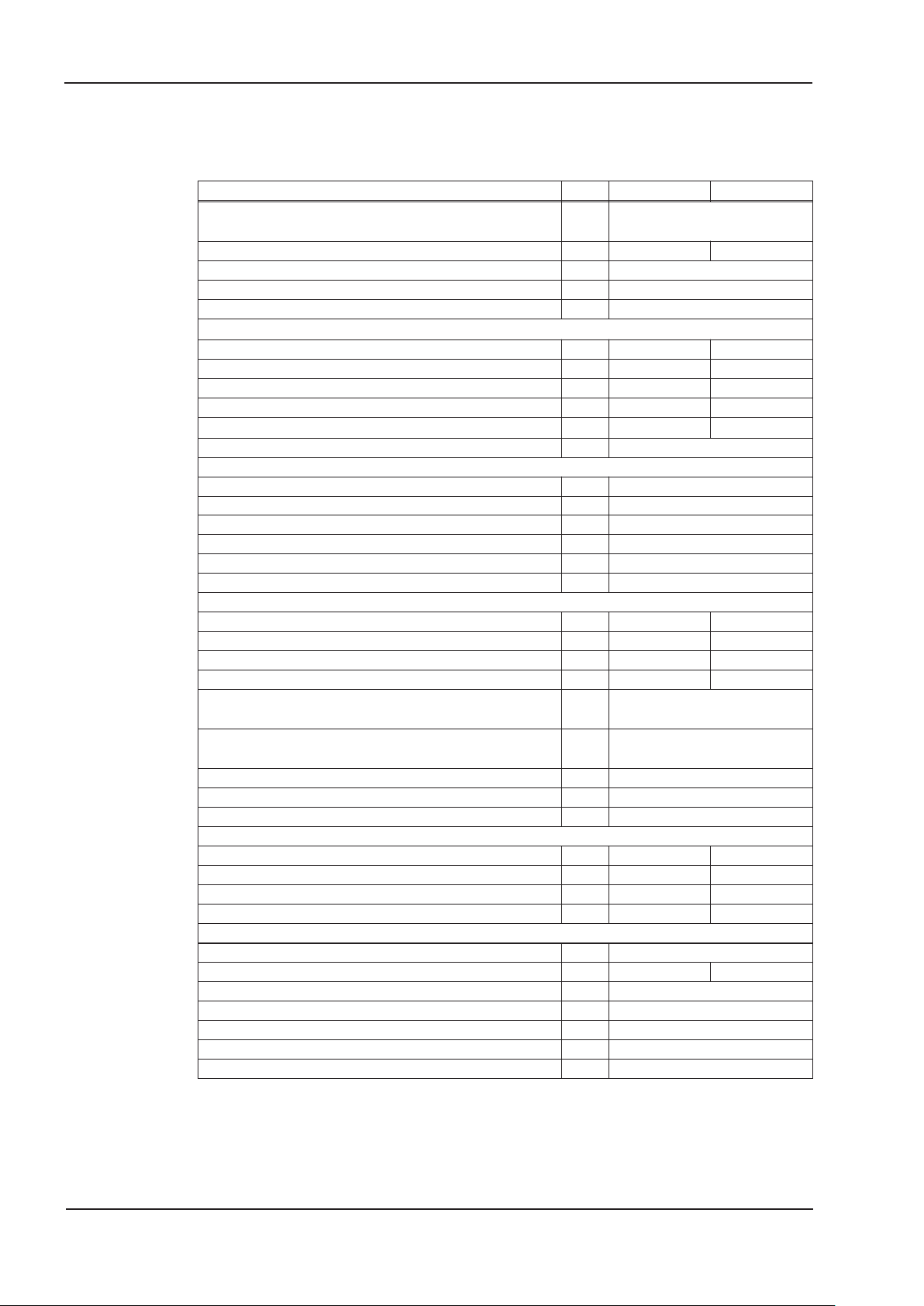
6.2 Technical data
6.2.1 Rated Data
Electrical data DIM S748 S772
Rated supply voltage (L1,L2,L3)
(grounded supply, phase to phase)
Rated input power for continuous operation kVA 35 50
Permitted switch on/off frequency 1/h 30
Auxiliary voltage supply — ð p.27
Rated DC bus link voltage V= 290 - 675
Rated output current (rms value, ± 3%)
at 3x208V Arms 48 72
at 3x230V Arms 48 72
at 3x400V Arms 48 72
at 3x480V Arms 48 72
Peak output current (for approx.5s, ± 3%)
Switching frequency of output stage kHz 8/16
Voltage rise speed dU/dt, (measured without connected motor, see hints on page 69!)
at 3x208V kV/µs 2.1
at 3x230V kV/µs 2.3
at 3x400V kV/µs 4.0
at 3x480V kV/µs 4.8
Technical data for brake circuit — ð p.31
Threshold for overvoltage switch-off VDC ð p.31
Motor inductance min.
at 3x208V mH 0.38 0.26
at 3x230V mH 0.42 0.29
at 3x400V mH 0.74 0.51
at 3x480V mH 0.88 0.61
Motor inductance max. mH
Form factor of the output current
(rated conditions, min. load inductance)
Bandwidth of current controller kHz > 1.2 (bis 5)
Residual voltage drop at rated current V 6
Thermal dissipation, output stage disabled, max. W 24
Thermal dissipation at rated current (without brake dissipation)
at 3x230V W 555 885
at 3x400V W 635 1005
at 3x480V W 685 1135
Noise emission max. dB(A) 62 68
Mechanical data
Weight kg 13
Weight Coldplate version (S7480C, S7480A) kg 10.4 Height, without connectors and shielding plate mm 386
Height, with connectors and shielding plate mm 505
Width mm 190
Depth, without connectors mm 244
Depth, with connectors mm 285
* In case of mains voltage below 300V, set parameters NONBTB=3 and VBUSBAL=1.
V~
Arms 96 140
— 1.01
3 x 208V
+10%
480V
Consult our customer
support
…3x
-10%
, 50/60 Hz
26 S748-S772 Instructions Manual
Page 27
Kollmorgen 11/2018 Technical description
6.2.2 Inputs / outputs, aux. voltage supply
Interface electr. data
Analog inputs1/2
Max. common-mode voltage
Digital control inputs
Digital control outputs
BTB/RTO output, relay contacts
24V-IO for digital outputs 20V … 30V
Auxiliary supply voltage, electrically isolated
Electronics 24V (-0% +15%)
Current electronics* 2A
Holding Brake 24V (-0% +15%)
Output current brake min./max. 0.15A / 3A
* = with fan but without option card
6.2.3 Connectors/Terminals
as per EN 61131-2 Type 1,
max. 30VDC, 15mA
as per EN 61131-2 Type 1,
max. 30VDC, 100mA
max. 30VDC, max 42VAC
±10V
±10V
500mA
Connector/Terminals Type
X0 Mains Terminals 35mm² 125A 1000V
X1 Encoder input SubD15poles (female) 0.5mm² 1A <100V
X2 Resolver input SubD 9poles (female) 0.5mm² 1A <100V
X3A, B Control signals Mini-Combicon connector 1.5mm² 4A 160V
X4 Aux. voltage, STO Mini-Combicon connector 1.5mm² 4A 160V
X5 optional, Encoder
emulation, ROD/SSI
SubD 9poles (male) 0.5mm² 1A <100V
X6 PC interface, CAN SubD 9poles (male) 0.5mm² 1A <100V
X7A, B EtherNET RJ45 connector
X8 DC Bus link, Motor,
Brake Resistor
Terminals 35mm² 125A 1000V
X9A, B Motor brake Mini-Combicon connector 1.5mm² 4A 160V
*1 single-line connection
*2 single-line connection with recommended conductor cross section (chapter 6.2.7)
*3 rated voltage with pollution level 2
6.2.4 Recommended tightening torques
Connection Tightening torque
X0 with up to 25mm² wire 2.5 Nm
X0 with 35mm² wire 4.5 Nm
X3A, B Cage clamps
X4 Cage clamps
X8with up to 25mm² wire 2.5 Nm
X8 with 35mm² wire 4.5 Nm
X9A
Grounding bolt 3.5 Nm
max. cross
section
*1
permiss.
current
FTP CAT.5, 26AWGx4P
as per EN50173
Cage clamps
Mounting flange: 0.5 Nm
permiss.
*2
voltage
*3
S748-S772 Instructions Manual 27
Page 28
Technical description 11/2018 Kollmorgen
NOTICE
NOTICE
6.2.5 Fusing
Internal fusing, wire fuse or electronic
Circuit S748…S772
24V Electronics 4 A
24V Motor brake 4 A
Brake resistor electronic
External fusing by user (US fuses in brackets)
Fusing information are explained in detail in the "KDN
".
S748 S772
AC Supply F
N1/2/3
24V Electronics F
24V Motor Brake F
Brake Resistor F
B1/2
H1/2
H3/4
60 A* 80 A*
8 A** 8 A**
8 A** 8 A**
100 A*** 100 A***
* EU fuses gRL or gL 400V/500V
US fuses: class RK5/CC/J/T, 600VAC 200kA, time-delay
** e.g. wire fuses or micro fuse or Automatic Circuit Brakers
*** EU fuses: Bussmann HLS, 690V/100A
US fuses: Bussmann FWP-xxA22F, Size 22x58mm, UL approved for 500Vdc
6.2.6 Ambient conditions, ventilation, mounting position
Storage hints
Transport hints
Surrounding air temperature in
operation
Humidity in operation
Site altitude
Pollution Level
Vibrations
Enclosure Protection
Mounting Position
Ventilation
The servo amplifier shuts down (error F01/F13, see p.120, motor has no torque) in case
of excessively high temperature in the control cabinet. Make sure that there is sufficient
forced ventilation within the control cabinet.
ð p.15
ð p.15
0...+40°C under rated conditions
+40...+55°C with power derating 2.5% / K
rel. humidity 85%, no condensation
up to 1000 meters a.m.s.l. without restriction
1000…2500 meters a.m.s.l. with power derating
1.5% / 100meters
Pollution level 2 as per IEC 60664-1
Class 3M1 according to IEC 60721-3-3
IP 20 according to IEC 60529
vertical ð p.52
built-in fan.
Kollmorgen requirements for servo amplifiers with Coldplate:
Flatness of the mounting (cooling) plate: £ 25 µm / 100 mm
Mains volt
age
-
Max. thermal resis
tance
-
Max. allowed temperatur:
Coldplate center
230V 0,063 K/W 75 °C
400V 0,055 K/W 75 °C
480V 0,051 K/W 75 °C
The cooling plate temperature must not be more than 10 K below the environment tem
perature. With a difference of more than 10 K there is a risk of condensation. Condensa
tion may destroy the electronics of the servo amplifier.
28 S748-S772 Instructions Manual
-
-
Page 29
Kollmorgen 11/2018 Technical description
NOTICE
6.2.7 Conductor cross-sections
Recommendations for cables (material and construction (ð p. 59)).
Following IEC 60204 (B2), we recommend for single-axis systems:
Interface Cross section Techn. requirements
AC connection
DC bus link
Brake resistor
Motor cables
Resolver, motor thermal control,
max.100m*
Encoder, motor thermal control,
max. 50m*
ComCoder, motor thermal con
trol, max. 25m
Set points, AGND, max 30m 0.25 mm² twisted pairs, shielded
Control signals, BTB, DGND,
max. 30m
Holding brake (Motor) min. 0.75 mm²
+24 V Electronics, max 30m max. 1.5 mm²
+24 V Motor brake, max 30m max. 1.5 mm²
For multi-axis systems, observe the specific operating conditions for your system.
To reach functional safety with the max. permitted cable length, observe cable
requirements ð p. 59.
* Kollmorgen North America supplies cables up to 39 meters
* Kollmorgen Europe supplies cables up to max. length
S748: 16 mm²
S772: 25 mm²
S748: 25 mm²
S772: 25 mm²
S748: 35 mm²
S772: 35 mm²
S748: 16 mm²
S772: 25 mm²
4x2x0.25 mm²
7x2x0.25 mm² twisted pairs, shielded
8x2x0.25 mm² twisted pairs, shielded
0.5 mm²
600V,80°C
1000V, 80°C,
shielded for lengths >0.50m
1000V, 80°C,
shielded for lengths >0.50m
600V,80°C,
shielded, C<150pF/m
twisted pairs,
shielded, C<120pF/m
600V, 80°C, shielded,
check voltage drop
check voltage drop
check voltage drop
6.3 LED display
A 3-character LED-Display indicates the status of the amplifier after switching on the 24V
supply (ð p.119). When the keys on the front panel are used, the parameter and function
numbers are shown, as well as the numbers for any errors and warnings that may occur
(ð p.120ff).
6.4 Grounding system
AGND analog inputs, internal analog ground
DGND 24V-IO, digital inputs and outputs, optically isolated.
GND internal digital ground, encoder Emulation, RS232, CAN
XGND 24V supply, STO Enable
BRGND 24V supply for the motor holding brake
S748-S772 Instructions Manual 29
Page 30
Technical description 11/2018 Kollmorgen
X3B/9-10
X3A/1
X4/5+X4/7
TBRAKE
STO-ENABLE 1/2
X9B/1-2
Analog-In
ENABLE
U
U
F
U
U
n
max.5s
tbrH
EMRGTO
DECDIS
VEL0
U
U
t
tbrL
TBRAKE0
t
t
t
t
t
t
t
5
Speed Setpoint
Braking force
BRAKE
internal
ENABLE
Speed
internal
ramp
stop ramp
emergency
NOTICE
CAUTION
6.5 Motor holding brake
A 24V holding brake in the motor can be controlled directly by the amplifier. A special 24V
supply voltage (X9B) is used. Brakes with up to 3A can be controlled directly.
No functional safety!
Danger by falling load (in case of suspended load, vertical axes). An additional
mechanical brake is required for functional safety, which must be safely operated, e.g.
via the Safety Card S1-2 (see p. 140).
The brake only works with sufficient voltage level (ð p.27). Check voltage drop, measure
the voltage at brake input and check brake function (brake and no brake).
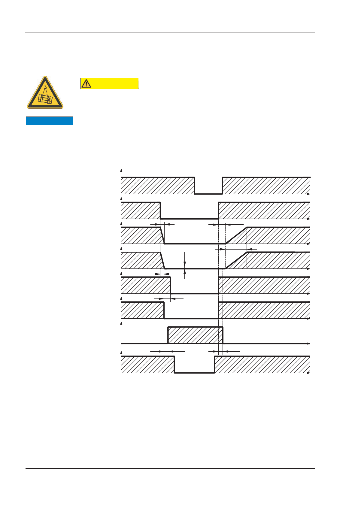
The brake function must be enabled through the BRAKE setting (screen page: Motor). In
the diagram below you can see the timing and functional relationships between the
ENABLE signal, speed setpoint, speed and braking force. All values can be adjusted with
parameters, the values in the diagram are default values.
30 S748-S772 Instructions Manual
During the internal ENABLE delay time of 100ms (DECDIS), the speed setpoint of the
servo amplifier is internally driven down an adjustable ramp to 0V. The output for the
brake is switched on when the speed has reached 5 rpm (VELO), at the latest after 5 s
(EMRGTO). The release delay time (t
) and the engage delay time (t
brH
) of the holding
brL
brake that is built into the motor are different for the various types of motor (see motor
manual), the matching data are loaded from the motor database when the motor is
selected. A description of the interface can be found on page 69.
Page 31

Kollmorgen 11/2018 Technical description
6.6 Dynamic Braking
During braking with the aid of the motor, energy is fed back into the servo amplifier. This
generated energy is dissipated as heat in the brake resistor. The brake resistor is
switched in by the brake circuit.
The setup software can be used to adapt the brake circuit (thresholds) according to the
electrical supply voltage.
Our customer service can help you with the calculation of the brake power that is neces
sary for your system. A simple method
interface can be found on page 67.
Functional description:
1.- Individual amplifiers, not coupled through the DC bus link circuit (DC+, DC-)
When the energy fed back from the motor has an average or peak power that exceeds
the preset level for the brake power rating, then the servo amplifier generates the warning
“n02 brake power exceeded” and the brake circuit is switched off.
The next internal check of the DC bus link voltage (after a few milliseconds) detects an
overvoltage and the output stage is switched off, with the error message “Overvoltage
F02” (ð p.120).
The BTB/RTO contact (terminals X3B/14,15) will be opened at the same time (ð p.99)
2.- Several servo amplifiers coupled through the DC bus link (DC+, DC-)
Using the built-in brake circuit, several amplifiers of the same series can be operated off a
common DC bus link (observe page 66), without requiring any additional measures.
90% of the combined power of all amplifiers is always available for peak and continuous
power. The switch-off on overvoltage takes place as described under 1. (above) for the
amplifier that has the lowest switch-off threshold (resulting from tolerances).
is described in the "KDN". A description of the
-
Technical data of the brake circuits depend on the mains voltage (VBUSBAL
Technical Data Brake Circuit Supply voltage (VBUSBAL
Rated data DIM 1: 230V 2: 400V 3*: 480V
Switch-on threshold of brake circuit V 400 720 840 790
Overvoltage F02 V 455 800 900 900
Pulse brake power kW 16 50 70 70
External brake resistor (RBe) for S748 Ohm 15
External brake resistor (RBe) for S772 Ohm 10
Continuous brake power external (RBe) kW 8
* Kollmorgen recommends setting VBUSBAL=4 in case of 480V mains supply, with this
setting the optimized calculation method is used.
Suitable external brake resistors can be found in our accessories manual.
).
)
4*: 480V
S748/772
S748-S772 Instructions Manual 31
Page 32

Technical description 11/2018 Kollmorgen
6.7 Switch-on and switch-off behavior
This chapter describes the switch-on and switch-off behavior of the S748/772 and the
steps required to achieve operational stopping or emergency stop behavior that complies
with standards.
The ASCII commands ACTFAULT
see ERRCODE
) and STOPMODE (Enable signal response) dictate how the drive will
(error response, also depends on the specific error,
behave.
ACTFAULT /
STOPMODE
0
1 (default)
Behavior (see also ASCII reference in the online help
ware)
Motor coasts to a standstill in an uncontrolled manner
Motor is braked in a controlled manner
of the setup soft
-
Behavior during a power failure
The servo amplifiers use an integrated circuit to detect if one or more input phases
(power supply feed) fail. The behavior of the servo amplifier is set using the setup soft
ware: Under “Response to Loss of Input Phase” (PMODE) on the Basic Setup screen,
select:
l
Warning if the higher-level control system is to bring the drive to a standstill: Warn
ing n05 is output if an input phase is missing, and the motor current is limited. The
servo amplifier is not disabled. The higher-level control system can now selectively
end the current cycle or start bringing the drive to a standstill. Therefore, the error
message “MAINS BTB, F16" is output on a digital output of the servo amplifier and
evaluated by the control system, for instance.
l
Error message if the servo amplifier is to bring the drive to a standstill: Error message F19 is output if an input phase is missing. The servo amplifier is disabled and
the BTB contact opens. Where the factory setting is unchanged (ACTFAULT=1), the
motor is braked using the set “EMERGENCY STOP RAMP”.
Behavior when undervoltage threshold is reached
If the undervoltage threshold is undershot in the DC bus link (the threshold value
depends on the type of servo amplifier), the error message “UNDERVOLTAGE, F05" is
displayed. The drive response depends on the ACTFAULT/STOPMODE setting.
Behavior with enabled “holding brake” function
Servo amplifiers with an enabled holding brake function have a special procedure for
switching off the output stage ( ð p. 30). Removing the ENABLE signal triggers electrical
braking.
As with all electronic circuits, the general rule applies that there is a possibility of the inter
nal “holding brake” module failing. Functional safety, e.g. with hanging load (vertical
axes), requires an additional mechanical brake which must be safely operated, e.g. via
the Safety Card S1-2.
Behavior of the safety function STO
With the functional safe restart lock STO, the drive can be secured on standstill using its
internal electronics so that even when power is being supplied, the drive shaft is pro
tected against unintentional restart. The chapter “Safety function STO” describes how to
use the STO function. See page 37 onwards.
-
32 S748-S772 Instructions Manual
Page 33

Kollmorgen 11/2018 Technical description
X4/5,7
X3B/14,15
SW-ENABLE
X3A/1 &
HW-ENABLE
n
U
U
> 100ms
STO-ENABLE
BTB/RTO
X8
L1,L2,L3
X0
X4/1,2
24V
< 15s (Boot-time)
U
U
U
U
5
t
t
VELO
t
t
5...8 min.
t
t
t
t
X4/6,8
STO-Status
t
U
~500ms
Motor speed
Power Stage
enable (inter
nal)
DC bus link
6.7.1 Behavior in standard operation
The behavior of the servo amplifier always depends on the current setting of a number of
different parameters (e.g., ACTFAULT, VBUSMIN, VELO, STOPMODE, etc. see online
help). The diagram below illustrates the correct functional sequence for switching the
servo amplifier on and off.
Devices which are equipped with a selected “Brake” function use a special sequence for
switching off the output stage (ð p.30).
safety is ensured at the drive shaft (ð p. 37).
The built-in safety function STO can be used to switch off the drive, so that functional
In case of a built-in safety card, wait for the Ready Acknowledge (X30 Pin 16) of the
safety card before enabling the servo amplifier again.
S748-S772 Instructions Manual 33
Page 34

Technical description 11/2018 Kollmorgen
ENABLE
extern
F06
24V
BTB/RTO
Boot-Time
~500ms
t
VELO
5
t
t
t
t
t
t
t
STO-ENABLE
t
> 100ms
Standard Operation
Motor Speed
Power Stage
Main Power
enable
DC-Bus
Fault Motor Temperature
Start
CAUTION
6.7.2 Behavior in the event of an error (with standard setting)
The behavior of the servo amplifier always depends on the current setting of a number of
different parameters (ACTFAULT, VBUSMIN, VELO, STOPMODE, etc.; see online help
Uncontrolled coasting!
Some faults (see ERRCODE ) force the output stage to switch-off immediately,
independant from the ACTFAULT
the load. An additional mechanical brake is required for funktional safety, which must be
safely operated
The diagram shows the startup procedure and the procedure that the internal control
system follows in the event of motor overtemperature, assuming that the standard param
eter settings apply. Fault F06 does not switch-off the output stage immediately, with
ACTFAULT=1 a controlled emergeny brake is started first.
setting. Danger of injury by uncontrolled coasting of
).
-
(F06 = error messages "Motor Temperature")
Even if there is no intervention from an external control system (in the example, the
ENABLE signal remains active), the motor is immediately braked using the emergency
stop ramp if this error is detected and assuming that no changes have been made to the
factory setting (ACTFAULT=1).
In case of a built-in safety card, wait for the Ready Acknowledge (X30 Pin 16) of the
safety card before enabling the servo amplifier again.
34 S748-S772 Instructions Manual
Page 35

Kollmorgen 11/2018 Technical description
6.8 Stop-, Emergency Stop-, Emergency Off Function to IEC 60204
With the functional safe, certified function STO (see page 37 onwards) the drive can be
secured on standstill (torque-free) using its internal electronics so that even when power
is being supplied, the drive shaft is protected against unintentional restart (SIL CL3
according to IEC 62061, PLe according to ISO 13849-1).
With built-in “Safety” expansion card, more safe drive functions in accordance with IEC
61800-5-2 (see page 150 ff) are provided.
The parameters “STOPMODE” and “ACTFAULT” must be set to 1 in order to implement
the stop and emergency stop categories. If necessary, change the parameters via the ter
minal screen of the setup software and store the data in the EEPROM.
Examples for implementation can be found in the KDN on page Stop and Emergency
Stop Function.
6.8.1 Stop
-
The Stop function is used to shut down the machine in normal operation. The Stop func
tions are defined by IEC 60204.
Category 0: Shut-down by immediate switching-off of the energy supply to the
drive machinery (i.e. an uncontrolled shut-down); this can be done
with the built-in STO functionality (see page 37)
Category 1: A controlled shut-down , whereby the energy supply to the drive
machinery is maintained to perform the shut-down, and the energy
supply is only interrupted when the shut-down has been completed;
Category 2: A controlled shut-down, whereby the energy supply to the drive
machinery is maintained.
The Stop Category must be determined by a risk evaluation of the machine. In addition,
suitable means must be provided to guarantee a reliable shut-down.
Category 0 and Category 1 Stops must be operable independently of the operating mode,
whereby a Category 0 Stop must have priority. Stop functions must be implemented by
disconnection of the appropriate circuitry, and have priority over assigned start func
tions.
If necessary, provision must be made for the connection of protective devices and
lock-outs. If applicable, the Stop function must signal its status to the control logic. A reset
of the Stop function must not create a hazardous situation.
Examples for implementation can be found in the KDN on page Stop and Emergency
Stop Function.
-
-
S748-S772 Instructions Manual 35
Page 36

Technical description 11/2018 Kollmorgen
6.8.2 Emergency Stop
The Emergency Stop function is used for the fastest possible shutdown of the machine
in a dangerous situation. The Emergency Stop function is defined by IEC 60204. Princi
ples of emergency stop devices and functional aspects are defined in ISO 13850.
The Emergency Stop function will be triggered by the manual actions of a single person.
It must be fully functional and available at all times. The user must understand instantly
how to operate this mechanism (without consulting references or instructions).
The Stop Category for the Emergency Stop must be determined by a risk evaluation of
the machine.
In addition to the requirements for stop, the Emergency Stop must fulfil the following
requirements:
l
Emergency Stop must have priority over all other functions and controls in all operat
ing modes.
l
The energy supply to any drive machinery that could cause dangerous situations
must be switched off as fast as possible, without causing any further hazards ( Stop
Category 0) or must be controlled in such a way, that any movement that causes
danger, is stopped as fast as possible (Stop Category 1).
l
The reset must not initiate a restart.
-
-
Examples for implementation can be found in the KDN on page Stop and Emergency
Stop Function.
6.8.3 Emergency Off
The Emergency Off function is used to switch-off the electrical power supply of the
machine. This is done to prevent users from any risk from electrical energy (for example
electrical impact). Functional aspects for Emergency Off are defined in IEC 60364-5-53.
The Emergency Off function will be triggered by the manual actions of a single person.
The result of a risk evaluation of the machine determines the necessity for an Emergency
Off function.
Emergency Off is done by switching off the supply energy by electro-mechanical switch
ing devices. This results in a category 0 stop. If this stop category is not possible in the
application, then the Emergency Off function must be replaced by other measures (for
example by protection against direct touching).
-
36 S748-S772 Instructions Manual
Page 37

Kollmorgen 11/2018 Technical description
6.9 Safety Function STO
A frequently required application task is the safe torque off and the protection of person
nel against unintentioned restarting of drives. The S748/772 servo amplifier offers, even
in the basic version, a two channel STO function (Safe Torque Off). The function blocks
the trigger pulses of the power transistors (pulse inhibitor).
Advantages of the safety function STO :
— the DC bus link remains charged up, since the mains supply line remains active
— only low voltages are switched, so there is no contact wear
— very little wiring is required
— single or dual channel control possible
— SIL2 or SIL3 solutions possible
The STO safety function corresponds to stop category 0 (uncontrolled stopping) acc. to
EN 60204-1. The safety function STO can be operated from external safety switch gears
(relays), from a safe external control (semiconductor output or driven contact) or from the
built-in safety card S1-2 or S2-2 (see p. 150).
The STO safety concept is certified by the TÜV. The safety circuit concept for realizing
the safety function "Safe Torque Off" in the servo amplifiers S748/772 is suited for
SIL CL3 according to IEC 62061 and PLe according to ISO 13849-1.
SIL2 / PLd solutions can be implemented with single-channel or dual-channel control with
simple safety switching devices.
A SIL3 / PLe solution requires a safety control that periodically tests the safe switching of
the pulse inhibitor by analyzing the feedback (status) signals.
-
6.9.1 Safety characteristic data
The subsystems (servo amplifiers) are totally described for safety technics with the
characteristic data SIL CL, PFH
Device Operation mode EN 13849-1 EN 62061 PFH
STO single channel PLd, Cat. 3 SIL CL 2 7,05E-08 20
STO dual channel PLd, Cat. 3 SIL CL 2 7,05E-08 20
STO
dual channel with
periodical testing
and TM.
D
[1/h] TM[Year]
D
PLe, Cat. 4 SIL CL 3 1,38E-09 20
S748-S772 Instructions Manual 37
Page 38

Technical description 11/2018 Kollmorgen
NOTICE
NOTICE
WARNING
CAUTION
WARNING
6.9.2 Safety notes
High electrical voltage!
Risk of electric shock! The function STO does not provide an electrical separation from
the power output. If access to the motor power terminals is necessary,
l
the S748/772 must be disconnected from mains supply,
l
consider the discharging time of the intermediate circuit.
No Brake Power!
Serious injury could result when a suspended load is not properly blocked. The servo
amplifier cannot hold a vertical load when STO is active.
l
Add a safe mechanical blocking (for instance, a motor-holding brake).
Uncontrolled movement!
Danger of personal injury. If STO is engaged during operation by separating input
STO1-Enable and STO2-Enable from 24 VDC, the motor runs down out of control and
the servo amplifier displays the error F27. There is no possibility of braking the drive
controlled.
l
Brake the drive in a controlled way first and then separate the STO inputs from +24
VDC time-delayed.
In case of single channel control:
If the STO is automatically activated by a control system, then make sure that the output
of the control is supervised for possible malfunction. This can be used to prevent a faulty
output from unintentionally activating the function STO. Since STO is used in a single-channel system, erroneous engaging will not be recognized.
Controlled braking:
Keep to the following functional sequence when STO is used :
1. Brake the drive in a controlled manner (speed setpoint = 0V)
2. When speed = 0 rpm, disable the servo amplifier (enable = 0V)
3. If there is a suspended load, block the drive mechanically
4. Activate STO (STO1-Enable and STO2-Enable = 0V
38 S748-S772 Instructions Manual
Page 39

Kollmorgen 11/2018 Technical description
6.9.3 Use as directed STO
The STO function is exclusively intended to provide functional safety, by preventing the
restart of a system. To achieve this functional safety, the wiring of the safety circuits must
meet the safety requirements of IEC 60204, ISO 12100, IEC 62061 respectively ISO
13849-1.
In case of single channel control: if STO is automatically activated by a control system,
then make sure that the output of the control is monitored for possible malfunction.
To achieve PLe or SIL CL3, the safe switching of the pulse inhibitor must be tested peri
odically by analyzing the feedback signal from the safety control (ð p. 47).
6.9.4 Prohibited Use STO
The STO function must not be used if the drive is to be made inactive for the following
reasons :
1. Cleaning, maintenance and repair operations, long inoperative periods:
In such cases, the entire system should be disconnected from the supply by the
personnel, and secured (main switch).
2. Emergency-stop situations:
In an emergency-off situation, switched off the main contactor (by the
emergency-off button).
6.9.5 Enlosure
Since the servo amplifier meets enclosure IP20, you must select the enclosure ensuring a
safe operation of the servo amplifier referring to the enclosure. The enclosure must meet
IP54 at least.
6.9.6 Wiring
When using STO wiring leads outside the control cabinet, the cables must be laid durably
(firmly), protected from outside damage (e.g. laying in a cable duct), in different sheathed
cables or protected individually by grounding connection. Wiring remaining within the
demanded enclosure must meet the requirements of the standard IEC 60204-1.
-
6.9.7 Technical Data
Input voltage
Input current
Peak current
Response time (falling edge at STO input
until energy supply to motor is interrupted)
20V..30V
33mA – 40mA (Ieff)
100mA (Is)
STO1: 1ms
STO2: 2ms
S748-S772 Instructions Manual 39
Page 40

Technical description 11/2018 Kollmorgen
SIL CL2, PLd
+24V
SIL CL3, PLe
SIL CL2, PLd
+24V
+24V
Safety Controller
+24V
+24V
1
2
X4
XGND
XGND
6
4
3
5
7
8
2
+24V
+24V
1
X4
XGND
XGND
3
5
4
7
6
8
X4
XGND
XGND
+24V
+24V
2
1
3
5
4
6
8
7
switchgear
safety
interlock
Single Channel
Dual Channel
interlock
interlock
interlock
interlock
Dual Channel
switchgear
safety
switchgear
safety
6.9.8 Technical data and pinning
A SIL3 / PLe solution requires a safety control that periodically tests the safe switching of
the pulse inhibitor by analyzing the status signals.
40 S748-S772 Instructions Manual
Page 41

Kollmorgen 11/2018 Technical description
NOTICE
6.9.9 Functional description
In case of use of the STO function the inputs STO1- Enable and STO2-Enable must be
connected to the exits of a safety control or a safety relay, which meets at least to the
requirements of the SIL CL2 according to IEC 62061 and PLd according to ISO 13849-1
(see the connection diagrams from page 43).
Possible states of the servo amplifier in connection with STO:
STO1-ENABLE
STO2-ENABLE
0 V 0 V -S- no yes
0 V +24 V F27 no yes
+24 V 0 V normal status e.g. 06 no no
+24 V +24 V normal status e.g. E06 yes no
SIL2/PLd Single Channel Control
With the single-channel control of the STO (SIL2/PLd) safety function, both switch-off
paths STO1-Enable and STO2-Enable are switched by one output of a safety switching
device (e.g. safety relay), see example ð p. 43.
In case of single channel usage of STO, erroneous engaging will not be recognized.
Therefore the output of the control must be supervised for possible malfunction.
SIL2/PLd Dual Channel Control
With the dual-channel control of the STO (SIL2/PLd) safety function, the switch-off paths
STO1-Enable and STO2-Enable are switched separately by two outputs of a safety
switching device (e.g. safety relay), see example on ð p. 44.
SIL3/PLe Dual Channel Control
With the dual-channel control of the STO safety function, the switch-off paths
STO1-Enable and STO2-Enable are switched separately by two outputs of a safety control, see example on ð p. 45.
To achieve PL e or SIL CL 3, the safe switching of the pulse inhibitor must be tested periodically by analyzing the feedback (status) signals from the safety control (ð p. 47).
ENABLE Display
Motor has
torque
SIL CL2 or 3
safety
When wiring the STO inputs within one enclosure it must be paid attention to the fact that
the used cables and the enclosure meet the requirements of IEC 60204-1.
If the wiring leads outside the demanded enclosure, the cables must be laid durably
(firmly), and protected from outside damage (see chapter 6.9.6).
If STO function is not needed in the application, then the inputs STO1-ENABLE and
STO2-ENABLE must be connected directly with +24VDC. STO is passed by now and
cannot be used. Now the servo amplifier is not a safety component referring to the EC
Machine Directive.
S748-S772 Instructions Manual 41
Page 42

Technical description 11/2018 Kollmorgen
n
U
U
Enable
STO1-Enable
t
t
t
X3A/1
X4/7
X4/5
STO2-Enable
U
t
³100ms
speed
6.9.9.1 Safe operation sequence
If a controlled braking before the use of STO is necessary, the drive must be braked and
the inputs STO1-ENABLE and STO2-Enable have to be separated from +24 VDC
time-delayed.
1. Brake the drive in a controlled manner (speed setpoint = 0V)
2. When speed = 0 rpm, disable the servo amplifier (enable = 0V)
3. If there is a suspended load, block the drive mechanically
4. Activate STO (STO1-Enable and STO2-Enable = 0V)
The diagram shows how STO should be used to ensure a safe stop of the drive and error
free operation of the servo amplifier.
42 S748-S772 Instructions Manual
Page 43

Kollmorgen 11/2018 Technical description
A1
A2
0V
A1
A2
K3
+24VDC
K1
23
24
S21
S34S12
PNOZ S3
S12S11
14
S22 13
F2
13
14
Reset
-S1
A2 S12 S34
S3
S4
23
24
11
12
2414
S22
E-Stop
-S2
PNOZ S3
A1 S11 S21S12
14
2313
F1
K2
BTB
15
X3B
X4
2
X4
4
5
7
X4
X4
BTB
15
14
Y2Y1
Mains
contactor
6.9.9.2 Control circuit single channel SIL CL2/PLd (example)
The example shows a circuit diagram with one axis connected to an emergency stop cir
cuit. The STO of the drives is switched by a protective screen. A single channel switch-off
is used. The safety switch gears used in the example are manufactured by Pilz and fulfill
at least the PLd acc. to ISO 13849-1. Further information to the safety switch gears is
available from Pilz. The use of safety switch gears of other manufacturers is possible, if
these also fulfill the SIL CL 2 according to IEC 62061 and PLd according to ISO 13849-1.
Emergency-stop circuit
acc. to ISO 13849-1
PLe
-
Safety function STO, SIL CL2 / PLd, single channel, 1 drive
Consider the wiring instructions on page 39.
S748-S772 Instructions Manual 43
Page 44

Technical description 11/2018 Kollmorgen
A2
A1
PNOZ S3
A2 S12 S34 14
24
S4
23
K1
K3
+24VDC
E-Stop
S22
S21S11A1 S12 S22 13
F2
S12
PNOZ S3
S11
Reset
-S1
A2
A1
S34
14
13
S12 S21
23
S3
11
14 24
13 23
K2
-S2
BTB
F1
14 15
24
12
Y1 Y2
0V
14
15
X4
7
5
X4
BTB
4
X4
2
X4
X3B
Mains
contactor
6.9.9.3 Control circuit dual channel SIL CL2/PLd (example)
The example shows a circuit diagram with one axis connected to an emergency stop cir
cuit. The STO of the drives is switched by a protective screen. A dual channel switch-off
is used. The safety switch gears used in the example are manufactured by Pilz and fulfill
at least the PLd acc. to ISO 13849-1. Further information to the safety switch gears is
available from Pilz. The use of safety switch gears of other manufacturers is possible, if
these also fulfill the SIL CL 2 according to IEC 62061 and PLd according to ISO 13849-1.
Emergency-stop circuit
acc. to ISO 13849-1
PLe
-
Safety function STO, SIL CL2 / PLd, dual channel, 1 drive
Consider the wiring instructions on page 39.
44 S748-S772 Instructions Manual
Page 45

Kollmorgen 11/2018 Technical description
A2
A1
A2
STO2-Enable
S4
23
K1
K3
+24VDC
E-Stop
S22
A1
S12
PNOZ S3
S11
Reset
-S1
A2
A1
S34
14
13
S12 S21
S3
11
14 24
13 23
K2
-S2
BTB
F1
14 15
14
15
24
BTB
12
Y1 Y2
X3B
STO1-Enable
0V
X4
7
5
X4
4
2
X4
STO2-Status
STO1-Status
X4
8
6
PNOZ mm0p
I2 I3 O0 O1
Mains
contactor
6.9.9.4 Control circuit dual channel SIL CL3/PLe (example)
The example shows a circuit diagram with one axis connected to an emergency stop cir
cuit. The STO of the drives is switched by a protective screen. A dual channel switch-off
is used. The safe switching of the pulse inhibitor must be tested periodically by analyzing
the feedback signals (status) in the safety control.
The safety controller used in the example is manufactured by Pilz and fulfills at least the
PLe acc. to ISO 13849-1. Further information to the safety controllers are available from
Pilz. The use of safety controlelrs of other manufacturers is possible, if these also fulfill
the SIL CL 3 according to IEC 62061 and PLe according to ISO 13849-1.
Emergency-stop circuit
acc. to ISO 13849-1
PLe
-
Safety function STO, SIL CL3 / PLe, dual channel, 1 drive
S748-S772 Instructions Manual 45
Consider the wiring instructions on page 39
Page 46

Technical description 11/2018 Kollmorgen
4
M
F4
PE
3
3
3
3
1
1
S3
S4
Safety door switch
mains 3~
NOTICE
6.9.9.5 Mains supply circuit (example)
S748/772
6.9.10 Functional test
6.9.10.1 SIngle or Dual Channel control, SIL CL2 / PLd
With initial starting and after each interference into the wiring of the drive or after
exchange of one or several components of the drive the function of STO must be tested.
1. Method:
1. Stop drive, with setpoint 0V, keep servo amplifier enabled (Enable=24V).
DANGER: Do not enter hazardous area!
2. Activate STO1-Enable and STO2-Enable e.g. by opening protective screen
(voltage at X4A/3=0V and X4B/6=0V).
Correct behavior: the BTB/RTO contact opens, the net contactor releases and the servo
amplifier displays error F27.
2. Method:
1. Stop all drives, with setpoint 0V, disable servo amplifier (Enable=0V).
2. Activate STO1-Enable and STO2-Enable e.g. by opening protective screen
(voltage at X4A/3=0V and X4B/6=0V).
Correct behavior: the servo amplifier displays -S-.
46 S748-S772 Instructions Manual
Page 47

Kollmorgen 11/2018 Technical description
U
U
Enable
STO1-Enable
t
t
X3A/1
X4/7
X4/5
STO2-Enable
U
t
U
X4/8
t
X3B/14,15
BTB/RTO
U
t
X4/1
24V DC
U
t
X4/6
U
Start
T1 T2 T3 T4 T5
End
t
6.9.10.2 SIL CL3 / PLe Dual Channel control
To achieve PLe / SIL CL3, the safe switching of the pulse inhibitor must be tested periodi
cally by analyzing the feedback signal from a safety control:
l
At the start of a system
l
At the restart after triggering a protective device
l
At least every 8 hours by the operator.
The inputs STO1-ENABLE and STO2-ENABLE are switched in turns according to a
defined test sequence. The switching states of the pulse inhibitor are available at the sta
tus outputs of the S748/772 and are analyzed by a safety control.
The test sequence for the functional test of the safe pulse inhibitor must be performed as
shown in the following time chart.
Prerequisites for the start of the test sequence:
l
Operational readiness BTB/RTO = “1"
l
Enable signal ENABLE = “0"
l
STO1-ENABLE and STO2-ENABLE = “0"
Legend:
-
-
STO1-ENABLE: digital input, 1st switch-off path STO2-ENABLE: digital input, 2nd switch-off path
STO1-STATUS: digital output, switching state of pulse inhibitor 1st switch-off path
STO2-STATUS: digital output, switching state of pulse inhibitor 2nd switch-off path
T1 … T5: Test sequence
Start: Start of test sequence End: End of test sequence
S748-S772 Instructions Manual 47
Page 48

Technical description 11/2018 Kollmorgen
6.10 Shock-hazard protection
6.10.1 Leakage current
Leakage current via the PE conductor results from the combination of equipment and
cable leakage currents. The leakage current frequency pattern comprises a number of
frequencies, whereby the residual-current circuit breakers definitively evaluate the 50Hz
current. As a rule of thumb, the following assumption can be made for leakage current on
our low-capacity cables at a mains voltage of 400 V, depending on the clock frequency of
the output stage:
I
= n x 20mA + L x 1mA/m at 8kHz clock frequency at the output stage
leak
= n x 20mA + L x 2mA/m at a 16kHz clock frequency at the output stage
I
leak
(where Ileak=leakage current, n=number of amplifiers, L=length of motor cable)
At other mains voltage ratings, the leakage current varies in proportion to the voltage.
Example: 2 x servo amplifiers + a 25m motor cable at a clock frequency of 8kHz:
2 x 20mA + 25m x 1mA/m = 65mA leakage current.
Since the leakage current to PE is more than 3.5 mA, in compliance with IEC 61800-5-1
the PE connection must either be doubled or a connecting cable with a cross-section
>10mm² must be used. Use the PE terminals and the PE bolt in order to fulfil this require
ment.
-
The following measures can be used to minimize leakage currents.
— Reduce the length of the engine cable
— Use low-capacity cables (see p.59)
— Remove external EMC filters (radio-interference suppressors are integrated)
6.10.2 Residual current protective device (RCD)
In conformity with IEC 60364-4-41 – Regulations for installation and IEC 60204 – Electrical equipment of machinery, residual current protective devices (called RCD below) can
be used provided the requisite regulations are complied with. The S748/772 is a 3-phase
system with a B6 bridge. Therefore, RCDs which are sensitive to all currents must be
used in order to detect any D.C. fault current.
Rated residual currents in the RCD
10 -30 mA
50 -300 mA
Recommendation: In order to protect against direct contact (with motor cables shorter
than 5 m) we recommend that each servo amplifier be protected individually using a
30mA RCD which is sensitive to all currents.
If you use a selective RCD, the more intelligent evaluation process will prevent spurious
tripping of the RCD.
Protection against "indirect contact" for stationary and mobile equipment,
as well as for "direct contact".
Protection against "indirect contact" for stationary equipment
6.10.3 Isolating transformers
When protection against indirect contact is absolutely essential despite a higher leakage
current, or when an alternative form of shock-hazard protection is sought, the S748/772
can also be operated via an isolating transformer (schematic connection see p.64). A
ground-leakage monitor can be used to monitor for short circuits.
Be advised to keep the length of wiring between the transformer and the servo amplifier
as short as possible.
48 S748-S772 Instructions Manual
Page 49

Kollmorgen 11/2018 Mechanical Installation
NOTICE
NOTICE
NOTICE
CAUTION
7 Mechanical Installation
7.1 Important notes
High leakage current!
There is a danger of electrical shock by high EMC level which could result in injury, if the
servo amplifier (or the motor) is not properly EMC-grounded.
l
Do not use painted (i.e. non-conductive) mounting plates.
l
In unfavourable circumstances, use copper mesh tape between the earthing bolts
and earth potential to deflect currents.
Protect the servo amplifier from impermissible stresses. In particular, do not let any com
ponents become bent or any insulation distances altered during transport and handling.
Avoid contact with electronic components and contacts.
The servo amplifier will switch-off itself in case of overheating. Ensure that there is an
adequate flow of cool, filtered air into the bottom of the control cabinet, or use a heat
exchanger. Please refer to page 28.
Don't mount devices, which produce magnetic fields, directly beside the servo amplifier.
Strong magnetic fields could directly affect internal components. Install devices which
produce magnetic field with distance to the servo amplifiers and/or shield the magnetic
fields.
7.2 Guide to mechanical installation
The following notes should help you to carry out the mechanical installation.
In a closed control cabinet. Please refer to page 28.
Site
Ventilation
The site must be free from conductive or corrosive materials.
For the mounting position in the cabinet ð p.52.
Check that the ventilation of the servo amplifier is unimpeded, and
keep within the permitted ambient temperature ð p.28. Keep the re
quired space clear above and below the servo amplifier ð p.52.
-
-
Assembly
Grounding
Shielding
Assemble the servo amplifier and power supply close together, on the
conductive, grounded mounting plate in the cabinet.
For EMC-compliant shielding and grounding ð p.63.
Ground the mounting plate, motor housing and CNC-GND of the
control system. Notes on connection techniques ð p.58.
S748-S772 Instructions Manual 49
Page 50

Mechanical Installation 11/2018 Kollmorgen
244
363
386
190
145
118
227
477
369
7.3 Dimensions
7.3.1 Device with heat sink
Material: four M5 hexagon socket screws to ISO 4762
50 S748-S772 Instructions Manual
Page 51

Kollmorgen 11/2018 Mechanical Installation
345
363.25
190
145
453
345
230
210
102.5
205
70
174
NOTICE
7.3.2 Device with Coldplate
These devices are not UL listed and are not EAC and Safety certified.
Material: six M5 hexagon socket screws to ISO 4762
S748-S772 Instructions Manual 51
Page 52

Mechanical Installation 11/2018 Kollmorgen
7.4 Assembly
7.4.1 Mounting the shielding plate
Material: unscrew existing screws and re-use them
Tool required : standard screw driver (cross)
52 S748-S772 Instructions Manual
Page 53

Kollmorgen 11/2018 Mechanical Installation
150
>50mm
385mm
>110mm
>2,5mm
M5
>285mm
1.5mm
150 15050 5030
>30
365mm
Cable duct
Cabinet door
conductive (zinc-coated)
mounting panel
screw for hex key EN 4762
>2"
15.16"
>4.3"
>0.1"
0.06"
>11.22"
Cable duct
14.37"
>1" 5.9" 5.9" 5.9"1.97" 1.97"
>1"
7.4.2 Backplane mounting - devices with heat sink
Material: four M5 hexagon socket screws to ISO 4762
Tool required:4mmAllen key
S748-S772 Instructions Manual 53
Page 54

Mechanical Installation 11/2018 Kollmorgen
NOTICE
>50mm
363.25mm
M5
200mm
30
210
50
210
50
210
30
102.5mm
70mm
102.5mm
M5
Cable duct
Cabinet door
mounting panel
>2"
14.30"
>4.3"
7.87"
Cable duct
>1"
8.27"
2"
2"
>1"
8.27"
8.27"
4.04"
2.76"
4.04"
7.4.3 Backplane mounting - devices with Coldplate
These devices are not UL listed and are not EAC and Safety certified.
Material: six M5 hexagon socket screws to ISO 4762
Ambient requirements see p.28, mounting plate flatness: £ 25 µm / 100 mm
Heat conducting film to increase the heat conduction, e.g. Kunze KU-CG20.
Tool required:4mmAllen key
54 S748-S772 Instructions Manual
Page 55

Kollmorgen 11/2018 Electrical installation
NOTICE
NOTICE
NOTICE
DANGER
8 Electrical installation
8.1 Important notes
High voltage up to 900V!
There is a danger of serious personal injury or death by electrical shock or electrical
arcing. Capacitors can still have dangerous voltages present up to 10 minutes after
switching off the supply power. Control and power connections can still be live, even if
the motor is not rotating.
l
Only install and wire the equipment when it is not live.
l
Make sure that the cabinet is safely disconnected (for instance, with a lock-out and
warning signs).
l
Never remove electrical connections to the drive while it is live.
l
Wait at least 10 minutes after disconnecting the drive from the main supply power
before touching potentially live sections of the equipment (e.g. contacts) or undoing
any connections.
l
To be sure, measure the voltage in the DC bus link and wait until it has fallen below
50 V.
Wrong mains voltage, unsuitable motor or wrong wiring will damage the amplifier.
Check the combination of servo amplifier and motor. Compare the rated voltage and current of the units. Implement the wiring according to the connection diagram on p. 57.
Make sure that the maximum permissible rated voltage at the terminals L1, L2, L3 or
+DC, –DC is not exceeded by more than 10% even in the most unfavorable circumstances (see IEC 60204-1).
Excessively high external fusing will endanger cables and devices. The fusing of the AC
supply input and 24V supply must be installed by the user, best values are given on p.28.
Hints for use of Residual-current circuit breakers (FI) ð p.48.
The servo amplifier's status must be monitored by the PLC to acknowledge critical situa
tions. Wire the BTB/RTO contact in series into the emergency off circuit of the installation.
The emergency off circuit must operate the supply contactor.
It is permissible to use the setup software to alter the settings of the servo amplifier. Any
other alterations will invalidate the warranty.
-
S748-S772 Instructions Manual 55
Page 56

Electrical installation 11/2018 Kollmorgen
NOTICE
NOTICE
8.2 Guide to electrical installation
Correct wiring is the basis for reliable functioning of the servo system.
Route power and control cables separately. We recommend a distance of at least
200mm. This improves the interference immunity. If a motor power cable is used that
includes cores for brake control, the brake control cores must be separately shielded.
Ground the shielding at both ends. Ground all shielding with large areas (low impedance),
with metalized connector housings or shield connection clamps wherever possible. Notes
on connection techniques can be found on page 58.
Feedback lines may not be extended, since thereby the shielding would be interrupted
and the signal processing could be disturbed. Lines between amplifiers and external
brake resistor must be shielded. Install all cables with an adequate cross-section, as per
IEC 60204 (ð p.29) and use the requested cable material (ð p. 59) to reach max. cable
length.
The following notes should help you to carry out the electrical installation.
Cable selection
Grounding
Shielding
Wiring
Select cables in accordance with IEC 60204 ð p.29.
For EMC-compliant shielding and grounding ð p.63.
Ground the mounting plate, motor housing and CNC-GND of the
control system. Notes on shield connection techniques ð p.58.
NOTE: Route power leads and control cables separately.
Wire the BTB/RTO contact in series into the emergency off
circuit of the system.
1. Connect the digital control inputs and outputs.
2. Connect the analog input source, if required.
3. Connect the feedback device.
4. Connect the expansion card
— (see corresponding notes from page 123).
5. Connect the motor cable
— Connect shielding at both ends.
6. Connect motor-holding brake, connect shielding at both ends.
7. Connect external brake resistor (with fusing)
8. Connect the auxiliary supply
— (maximum permissible voltage values ð p.28).
9. Connect the main electrical supply
— (maximum permissible voltage values ð p.28), hints for use of
Residual-current circuit breakers (FI) ð p.48
10.Connect the PC (ð p.100).
Final check
Final check of the implementation of the wiring against the wiring
diagrams that have been used.
56 S748-S772 Instructions Manual
Page 57

Kollmorgen 11/2018 Electrical installation
DANGER
8.3 Wiring
The installation procedure is described as an example. A different procedure may be
appropriate or necessary, depending on the application of the equipments.
We provide further know-how through training courses (on request).
High voltage up to 900V!
There is a danger of electrical arcing with damage to contacts and serious personal
injury.
l
Only install and wire up the equipment when it is not live, i.e. when neither the elec
trical supply nor the 24 V auxiliary voltage nor the supply voltages of any other con
nected equipment is switched on.
l
Make sure that the cabinet is safely disconnected (for instance, with a lock-out and
warning signs).
-
-
The ground symbol
must take care to provide an electrically conductive connection with the largest feasible
surface area between the unit indicated and the mounting plate in the control cabinet.
This connection is for the effective grounding of HF interference, and must not be con
fused with the PE-symbol W (PE = protective earth, safety measure as per IEC 60204).
Use the following connection diagrams:
Overview : page 63
Restart lock STO : page 43
Mains power : page 65
Motor : page 69
Feedback : page 71ff
Electronic Gearing / Master Slave
Master-Slave : page 90
Pulse-Direction : page 91
Digital and analog inputs and outputs : page 95ff
RS232 / PC : page 100
CAN Interface : page 101
EtherNET Interface : page 102
Expansion cards for slot 1:
I/O-14/08 : page 126
PROFIBUS : page 127
®
sercos
DeviceNet : page 130
SynqNet : page 134
FB-2to1 : page 135
2CAN : page 137
Expansion cards for slot 2:
PosI/O & PosI/O-Monitor : page 140ff
Expansion cards for slot 3:
PosI/O & PosI/O-Monitor : page 136ff
Safety : page 150ff
X, which you will find in all the wiring diagrams, indicates that you
II : page 129
-
S748-S772 Instructions Manual 57
Page 58

Electrical installation 11/2018 Kollmorgen
8.3.1 Shielding connection to the front panel
Remove the outside shroud of the cable
and the shielding braid on the desired core
length. Secure the cores with a cable tie.
Remove the outside shroud of the line on a
length from for instance 30mm without da
maging the shielding braid.
Strip all wires and fit wire end ferrules.
Use cable ties to attach the cable to the
side (1) shroud or bottom (2) shielding plate
of the servo amplifier, securing the braided
shield of the cable to the shroud of the
servo amplifier with a cable tie.
-
Alternatively you can use shield connection
terminal clamps (see accessories manual).
These hook into the bottom shroud and ensure optimum contact between the shield
and the shroud.
Wire the plug-in terminal blocks as shown in
the connection diagram.
The motor cable shield is connected via a
shield connection clamp to the bottom shielding plate (3). Clamp and shielding plate
are part of delivery.
58 S748-S772 Instructions Manual
Page 59

Kollmorgen 11/2018 Electrical installation
U
V
W
PE
3~
M
SHIELD
Capazity Phase-to-Shield
Core Isolation
Core
Isolation
Fill material
Shield
8.3.2 Technical data for connecting cables
For further information on the chemical, mechanical and electrical characteristics of the
cables please refer to the accessories manual or contact our customer service.
Observe the rules in the section "Conductor cross-sections" on page 29. To reach the
max. permitted cable length, you must use cable material that matches the capacitance
requirements listed below.
Capacitance (core to shield)
Motor cable less than 150 pF/m
Resolver/Encoder cable less than 120 pF/m
Example: Motor cable
Technical data
For a detailed description of Kollmorgen cable types and how to assemble them, please
refer to the accessories manual.
Chokes
With motor cables longer than 25m the use of a motor choke 3YLN may be necessary
depending on the system. Contact our customer support.
If mains voltage is more than 3% asymmetrical, a mains choke 3L with 2% uk must be
used. See Accessories Manual.
S748-S772 Instructions Manual 59
Page 60

Electrical installation 11/2018 Kollmorgen
8.4 Components of a servo system
Mains
PC
Drive cut-out
S748/S772
EtherNET
Feedback cable
PLC
Brake Resistor
Power Cable
Brake Cable
24V PSU
Motor
Mains
Cables drawn bold are shielded. The required accessories are described in our accesso
ries manual.
-
60 S748-S772 Instructions Manual
Page 61

SinCos
RDC
XGND
+24V
X4
4AM
Analog-In 2+
Analog-In 2-
AGND
+
-AS-
-
D
A
DIGITAL-INOUT2
DIGITAL-INOUT1
DIGITAL-IN2
DIGITAL-IN1
Analog-In 1-
Analog-In 1+
BTB/RTO
BTB/RTO
ENABLE
DIGITAL-IN4
DIGITAL-IN3
X3
CAN
RS232
X6
-AS-
+
-
D
A
CAN
RS
232
-DC
X9
BRAKE+
X1
X2
I
D
A
U1
BRAKE-
M3~
V1
U2
V2
W2
~
=
X8
G
-RB
+RB
D
A
X8
X0
L1
L3
PE
L2
Comcoder
X1
STO1-ENABLE
X4
+24V-IO
DGND
X7
EtherCat
ETHER
NET
SynqNet
TCP/IP
X9
BR +24V
BRGND
X3
X3
W1
+DC
STO1-STATUS
STO2-STATUS
STO2-ENABLE
VBUS
or
EMI
Intermediate circuit
Inrush circuit
Power stage
Encoder
Resolver
or
EMI
Controller
Internal power supply
Kollmorgen 11/2018 Electrical installation
8.5 Block diagram
The block diagram below just provides an overview.
S748-S772 Instructions Manual 61
Page 62

Electrical installation 11/2018 Kollmorgen
DIGITAL-IN21/OUT1
DIGITAL-IN22/OUT2
X6 PC/CAN
CANL
CANH
BTB/RTO
3
Analog-In 1+
Analog-In 1-
Analog-In 2-
Analog-In 2+
DIGITAL-IN3
DIGITAL-IN4
ENABLE
DIGITAL-IN1
DIGITAL-IN2
DGND
8
7
6
5
4
BTB/RTO
2
1
1
6
7
9
8
TxD
3
RxD
2
reserve
4
GND
5
X1
13
S1
8
9
R1
R2
5
S3
4
S2
7
ä
6
SHIELD
1
ä
2
S4
3
14
15
8
7
6
10
12
11
9
3
4
5
2
1
14
16
15
11
13
12
10
9
+24V-IO
AGND
X3B
X7B
Ethernet
I/O
X3A
X4
24V/STO
BR+
BR-
1
2
X9A
X9B
2
1
BR+24V
BRGND
L3
L2
L1PE
-RB
V2W2
+RB -DC
U2
PE+DC
X7A
Ethernet
+24V
+24V
1
2
STO2-ENABLE
STO1-ENABLE
STO1-STATUS
STO2-STATUS
XGND
XGND
6
4
3
5
7
8
n.c.
built-in connectors
thefaceofthe
X8 motor/brake
X0 Mains
Coding Keys
Brake
ENCODER
8.6 Connector assignments
62 S748-S772 Instructions Manual
Page 63

Kollmorgen 11/2018 Electrical installation
S748...S772
X6
X7
X3A/B
FN3
FN2
FB2
PE L1 L2 L3
FN1
FH3
FH1
FH2
24V DC
3
1
1
3
2
4
L3
+24V
XGND
PE
X4
L2
L1
+RB
-RB
X0
FB1
U1
M
B+
B-
PE
W1
V1
digital
2
1
8
PE
BR+
BR-
U2
X8
W2
V2
X8
X2
X1
PC
CAN
BTB/RTO
Ethernet
3
3
15
COM1/COM2
CAN-Master
DIGITAL-IN22/OUT2
DIGITAL-IN3
DIGITAL-IN4
ENABLE
DIGITAL-IN21/OUT1
DIGITAL-IN1
DIGITAL-IN2
4
6
7
14
1
5
2
3
6
Analog-In 2-
Analog-In 2+
Analog-In 1-
Analog-In 1+
AGND
11
12
13
9
10
Digital2
Digital1
CNC-GND
CNC-GND
-
+
-
+
STO2-ENABLE
5
X4
Feedback
I/O-14/08
PROFIBUS
SERCOS
DEVICENET
SYNQNET
DGND
16
+24V-IO
8
EtherCat
SynqNet
A
B
X9A
X9B
1
2
BRGND
BR +24V
24V DC
4
FBR
4
I/O-GND
STO1-ENABLE
7
XGND
8
Status 2
Status 1
STO2-STATUS
STO1-STATUS
Safety
- S1.2 (S3)
- S2.2 (S4)
Mains
contactor
supply unit
Resolver
or
included
Resolver
thermal control
included
thermal control
PE-connection (protective earth)
shield connection at the front panel
shield connection via plug
chassis ground connection (panel)
to 0V/GND
+24V referred
+/-10V speed
setpoint2
referred to
CNC-GND
CNC-GND
referred to
setpoint1
+/-10V speed
Control
Participant
Participant
Emerg.
Stop
supply unit
Brake
resistor
Circuit
Encoder
8.7 Connection Diagram (Overview)
Reference Safety Instructions (ð p.11)
and Use As Directed (ð p.13) !
ð p.70ff
ð p.74
ð p.69
ð p.70
ð p.67
ð p.65
ð p.65
ð p.96
ð p.96
ð p.98
ð
ð p.100
ð p.95
S748-S772 Instructions Manual 63
Page 64

Electrical installation 11/2018 Kollmorgen
208...480V
208...240V
208...240V
208...240V
208...240V
208...240V
400...480V
400...480V
400...480V
400...480V
400...480V
PE
L3
L2
L1
L3
PE
L2
L1
PE
L3
L1
L2
PE
L3
L2
L1
PE
L3
L2
L1
1:1
PE
L2
L3
L1
L3
PE
L2
1:1
1:1
1:1
L1
L3
PE
L1
L2
L3
PE
L1
L2
L2
PE
L3
1:1
PE
L1
L2
L3
L1
mains
mains
mains
mains
Isolating transfo
Isolating transfo
Isolating transfo
mains
Isolating transfo
Isolating transfo
mains
mains
mains
mains
mains
mains
NOTICE
8.8 Electrical supply
8.8.1 Connection to various mains supply networks
An isolating transformer is required for 400V to 480V networks that are asymmetrically
grounded or not grounded as shown below.
S748/772
S748/772
S748/772
S748/772
S748/772
S748/772
S748/772
S748/772
S748/772
64 S748-S772 Instructions Manual
S748/772
S748/772
Page 65

Kollmorgen 11/2018 Electrical installation
~
=
L2
L1
X0
L3
PE
F
N2
FN1
FN3
L1
L3
L2
PE
~
=
L2
L1
X0
L3
PE
F
N2
FN1
FN3
L1
L3
L2
PE
U2
V2
W2
U1
V1
W1
3L...
NOTICE
XGND
XGND
+24V
+24V
+24V
4AM
3
4
1
2
-
-
+
PE
L3
L2
L1
X4
8.8.2 Mains supply connection (X0)
— Directly to 3-phase supply network, filter is integrated, supply networks ð p.64
(with mains voltage below 300V set parameters NONBTB=3 and VBUSBAL=1.)
— Fusing (e.g. fusible cut-outs) to be provided by the user ð p.28
— Screw driver for plus-minus-screws (Combiprofile Slotted/Pozidriv) size 2
S748/772
If mains voltage is more than 3% asymmetrical, a mains choke 3L with 2% uk must be
used. See Accessories Manual. For EMC reasons the choke should be mounted electri
cally isolated to the cabinet.
-
S748/772
8.8.3 24V auxiliary supply (X4)
— External 24V DC power supply, electrically isolated, e.g. via an isolating transformer
— Required current rating ð p.26
— Integrated EMC filter for the 24V auxiliary supply
S748/772
S748-S772 Instructions Manual 65
Page 66

Electrical installation 11/2018 Kollmorgen
X8
X8
-DC
FB2
RBext
FB1
-DC
+DC
-RB
+RB+RB
-RB
-DC
+DC
-DC
+RB
-DC
-RB
X8
-DC
+DC
NOTICE
8.9 DC bus link (X8)
Terminals X8/-DC and X8/+DC. Can be connected in parallel, whereby the brake power
is divided between all the amplifiers that are connected to the same DC bus link circuit.
— Screw driver for plus-minus-screws (Combiprofile Slotted/Pozidriv) size 2
In case of mains supply from the same mains (identical mains supply voltage) three servo
amplifiers S748/772 may be connected by the DC bus link.
l
The servo amplifiers can be destroyed, if DC bus link voltages are different. Only
servo amplifiers with mains supply from the same mains (identical mains supply volt
age) may be connected by the DC bus link.
l
The setting of VBUSBAL must be identical with all devices on the bus.
l
The sum of the rated currents for all of the servo amplifiers connected in parallel to
an S748/772 must not exceed 96 Arms (140 Apeak).
l
Use unshielded single cores (cross section see p. 29) with a max. length of 500mm.
Use shielded cables for longer lengths.
l
Servo amplifiers working generatively very often, should be placed beside amplifiers,
which need energy. That reduces current flow on longer distances.
-
Fusing information are explained in detail in the KDN on page "DC Bus link in parallel
S748
S748
S748
".
66 S748-S772 Instructions Manual
Page 67

Kollmorgen 11/2018 Electrical installation
S700 S700 S700 S700 S700 S700
DC DC DC DC DC DC
X8
FB1+RB
FB2-RB
RBext
+DC
-DC
8.9.1 DC Bus topology
Without intermediate circuit fuses, other devices can become damaged or destroyed if,
for example, a device fails due to an internal short circuit. If a device fails due to a
short-circuit, only its intermediate fuses are tripped and the rest of the network continues
uninterrupted. Fuses cannot avoid damage by current peaks completely.
Fuse types: see section "Fuses" on page 28.
The solid busbars can conduct large currents. For this reason, almost as many servo
amplifiers as desired can be connected in parallel in this form.
8.9.2 External brake resistor (X8)
An external brake resistor can be connected to X8 (-RB, +RB). Fuse types: see section
"Fuses" on page 28. Information for brake circuit and technical data can be found on
page 31.
If you want to link the DC bus with neighbored S748/772 servo amplifiers, see connection
example on page 66, Chapter "DC Bus link".
— Screw driver for plus-minus-screws (Combiprofile Slotted/Pozidriv) size 2
S748/772
S748-S772 Instructions Manual 67
Page 68

Electrical installation 11/2018 Kollmorgen
DANGER
8.9.3 Capacitor Module KCM (X8)
KCM modules (KOLLMORGEN Capacitor Modules) absorb energy gen
erated by the motor when it is operating in generator mode. Normally,
this energy is dissipated as waste via brake resistors. KCM modules,
however, feed the energy they have stored back into the DC Bus link as
and when it is required.
Dimensions (HxWxD) : 300x100x201 mm
KCM-S Saves energy: The energy stored in the capacitor module during regenerative
braking is available the next time acceleration happens. The module’s inception
voltage is calculated automatically during the first load cycles.
KCM-P Power in spite of power failure: If the power supply fails, the module provides
the servo amplifier with the stored energy that is required to bring the drive to a
standstill in a controlled manner (this only applies to the power supply voltage;
battery-back the 24 V supply separately).
KCM-E Expansion module for both applications. Expansion modules are available in
two capacitance classes.
The KCM modules can be connected to S7010 ... S7480 devices (mains supply voltage
400/480V). Information for mounting, installation and setup can be found in the KCM
Instructions Manual and in
KDN.
Technical Data of KCM Modules
Storage
capacity
Type [Ws] [V DC] [V DC] [kW] [V DC] [kg]
KCM-S200 1600
KCM-P200 2000 470 VDC 6,9
KCM-E200 2000 - 4,1
KCM-E400 4000 - 6,2
Rated sup-
ply
voltage
max.
850 VDC
Peak supply
voltage
max.
950 VDC
(30s in 6min)
Power
18 IP20
Protec-
tion
class
Inception
voltage
evaluated 6,9
Weight
-
High DC voltage up to 900 V!
There is a danger of serious personal injury or death by electrical shock or electrical
arcing. It can take over an hour for the modules to self-discharge.
l
Switch off (disconnect) the line voltage. You must only work on the connections
when the system is disconnected.
l
Check the state of charge with a measuring device that is suitable for a DC voltage
of up to 1,000 V.
l
When measuring a voltage of over 50V between the DC+/DC- terminals or to
ground, wait some minutes and measure again or discharge the modules as de
scribed in the KCM instructions manual.
-
68 S748-S772 Instructions Manual
Page 69

Kollmorgen 11/2018 Electrical installation
NOTICE
X8
W2
V2
U2
PE
M
W
V
U
PE
W2
V2
U2
PE
X8
M
3L
W1
V1
U1
PE
U
V
W
U1
V1
W1
NOTICE
8.10 Motor connection
8.10.1 Motor Power Connection (X8)
The S748/772 drive is able to protect the connected motor from overloading, if the param
eters are set correctly and the thermal protection sensor is connected and supervised.
With Kollmorgen motors the valid data are automatically set by the internal motor data
base. With motors from other manufacturers the data from the nameplate must be
entered to the referring fields in the motor view of the setup software DriveGUI.
Together with the motor supply cable and motor winding, the power output of the servo
amplifier forms an oscillating circuit. Characteristics such as cable capacity, cable length,
motor inductance, frequency and voltage rise speed (see Technical Data, p. 26) deter
-
mine the maximum voltage in the system.
The dynamic voltage rise can lead to a reduction in the motor’s operating life and, on
unsuitable motors, to flash overs in the motor winding.
— Only install motors with insulation class F (acc. to IEC 60085) or above
— Only install cables that meet the requirements on p.29 and p.59
Use screw driver for plus-minus-screws (Combiprofile Slotted/Pozidriv) size 2
Standard applications up to 25m cable length
S748/772
-
Application with cable length >25m and special conditions
With long motor cables overvoltage may endanger the motor winding. For cable lengths
above 25m a motor choke 3YLN may be wired into the motor cable, close to the amplifier.
Contact our customer support.
S748/772
S748-S772 Instructions Manual 69
Page 70

Electrical installation 11/2018 Kollmorgen
BRGND
2
X9B
1
BRGND
BR +24V
24V
BRGND
MarkusGrohnert
Sigismundstr.16
45470Mülheim
1
2
X9A
-
+
~
=
L3
PE
L2
L1
M
BR-
BR+
Brake+
Brake-
CAUTION
8.10.2 Motor holding brake (X8, X9B)
The motor holding brake can be controller by the servo amplifier. An external 24V supply
voltage delivers the required electrical power for the connected brake. Observe the
requirements to the supply voltage listed on page 27.
No functional safety!
Serious injury could result when a suspended load is not properly blocked.
l
An additional mechanical brake is required for functional safety, which must be
safely operated, e.g. via the Safety Card S1-2 (see p. 140).
8.11 Feedback Systems
S748/772
Every closed servo system will normally require at least one feedback device for sending
actual values from the motor to the servo drive. Depending on the type of feedback
device used, information will be fed back to the servo amplifier using digital or analog
means. Up to three feedback devices can be used at the same time.
S748/772 supports the most common types of feedbacks whose functions must be
assigned in the setup software DRIVEGUI.EXE with the parameters:
FBTYPE (screen page FEEDBACK), primary Feedback
EXTPOS (screen page POSITION CONTROLLER), secondary Feedback
GEARMODE (screen page ELECTRONIC GEARING), secondary Feedback (ð p.83)
Scaling and other settings must always be made in the software. For a detailed descrip
tion of the ASCII parameters, please refer to the online help
of the setup software.
-
70 S748-S772 Instructions Manual
Page 71

Kollmorgen 11/2018 Electrical installation
SFD3
HIPERFACE DSL
8.12 Primary and secondary feedback types
This chapter provides an overview of the supported feedback types, their corresponding
parameters and a reference to the relevant connection diagram in each case.
Single Cable connection (Power and Feedback in one cable)
Hybrid cables on request
primary secondary
Feedback type Connector Wiring FBTYPE EXTPOS
SFD3 X1
HIPERFACE DSL X1
ð p.72
ð p.73
Dual cable connection (Power and Feedback separated)
Motor cables and Feedback cables
see Accessories Manual
36 35 -
primary secondary
Feedback type
Connec-
tor
Resolver X2
SinCos Encoder BiSS (B) analog X1
2)
SinCos Encoder BiSS (B, C
) digital X1
SinCos Encoder ENDAT 2.1 X1
Encoder ENDAT 2.2 X1
SinCos Encoder HIPERFACE X1
SinCos Encoder SSI (linear) X1
SinCos Encoder w/o data channel X1
SinCos Encoder + Hall X1
ROD* 5V without zero, 1.5MHz X1
ROD (AquadB) 5V with zero, 350kHz X1
ROD (AquadB) 5V with zero + Hall X1
ROD (AquadB) 24V without zero X3
ROD (AquadB) 24V without zero + Hall X3/X1
SSI X1
Hall X1
Step/Direction 24V X3
Wiring
diagram
ð p.74
ð p.75
ð p.76
ð p.77
ð p.78
ð p.79
ð p.80
ð p.81
ð p.82
ð p.83
ð p.84
ð p.85
ð p.86
ð p.87
ð p.88
ð p.89
ð p.91
FBTYPE EXTPOS
0-
23, 24 -
20, 22, 33 11, 12
4, 21 8
32, 34 13
29
1)
26
1, 3, 7, 8 6, 7
5, 6 30, 31 30
17, 27 10
15 -
12, 16 2
14 -
1)
25
11 -
-1
Sensorless (w/o Feedback) - - 10 -
with expansion card "PosI/O" or "PosI/O-Monitor"
1)
1)
ROD (AquadB) 5V with zero X5
ROD (AquadB) 5V with zero + Hall X5/X1
SSI X5
SinCos Encoder SSI (linear) X1
Step/Direction 5V X5
* ROD is an abbreviation for “incremental encoder”.
1)
Switch on the encoder supply voltage on X1: set ENCVON to 1
2)
BiSS C support for Renishaw sncoders, Hengstler encoders are not supported.
ð p.141
ð p.142
ð p.143
ð p.144
ð p.145
,19
13
18 -
1)
9
28 -
-4
-
25
3
5
The expansion card FB2to1 (see p. 135) enables simultaneous connection of a digital pri
mary and of an analog secondary feedback to the connector X1.
S748-S772 Instructions Manual 71
-
Page 72

Electrical installation 11/2018 Kollmorgen
SFD3
D
C
A
B
8
15
X1
0V
4
2
Up
COM+
COM-
X9
1
2
4
5
6
3
Brake-
Brake+
PE
U2
V2
W2
BR-
BR+
PE
U
V
W
B
A
1
4
3
2
Drive
max. 250mA
Motor
Power
Brake
8.12.1 SFD3 (X1), single cable connection
Connection of the Kollmorgen feedback system SFD3 (primary, ð p.71). SFD3 can be
used only with the special Kollmorgen hybrid cable (on request).
Maximum cable length 25 m.
FBTYPE: 36
The pin assignment shown on the encoder side relates to the Kollmorgen motors (connector code D).
72 S748-S772 Instructions Manual
Page 73

Kollmorgen 11/2018 Electrical installation
A
B
8
15
X1
Feedback
0V
4
2
Up
DSL+
DSL-
COM+
COM-
D
C
X9
1
2
4
5
6
3
Brake-
Brake+
PE
U2
V2
W2
BR-
BR+
PE
U
V
W
B
A
1
4
3
2
HIPERFACE DSL
Drive
max. 250mA
Motor
Power
Brake
8.12.2 HIPERFACE DSL (X1), single cable connection
Connection of HIPERFACE DSL feedback (primary, ð p.71). HIPERFACE DSL can be
used only with the special Kollmorgen hybrid cable (on request).
Maximum cable length 25 m.
FBTYPE: 35
The pin assignment shown on the encoder side relates to the Kollmorgen motors (connector code D).
S748-S772 Instructions Manual 73
Page 74

Electrical installation 11/2018 Kollmorgen
2
6
100µH
4
5
9
8
3
7
X2
2
6
4
5
9
8
3
7
R1
R2
S1
S3
S4
S2
100µH14R7
4R7
min. 5VDC/5mA
Resolver
thermal control
Motor
8.12.3 Resolver (X2)
Connection of a Resolver (2 to 36-poles) as a feedback system (primary, ð p.71). The
thermal control in the motor is connected via the resolver cable to X2 and evaluated
there.
If cable lengths of more than 100m are planned, please consult our customer service.
FBTYPE: 0
S748/772
SubD9
12pol.round
The pin assignment shown on the encoder side relates to the Kollmorgen motors.
74 S748-S772 Instructions Manual
Page 75

Kollmorgen 11/2018 Electrical installation
max. 250mA
0V
2
10k
10k
Sense
UP
UP
0V
B
A
-
+
A
B
12
10
8
4
15
3
11
5
13
10k
10k
-
+
9
1
X1
2
0V
11
12
10
13
15
4
8
5
3
CLOCK
CLOCK
Sense
UP
UP
0V
A+
A-
9
1
B-
B+
min. 5VDC/5mA
77
1414
voltage supply
Motor
sine
cosine
thermal control
Encoder
8.12.4 Sine Encoder with BiSS analog (X1)
Wiring of a single-turn or multi-turn sine-cosine encoder with BISS interface as a feed
-
back system (primary, ð p.71).
The thermal control in the motor is connected via the encoder cable to X1 and evaluated
there. All signals are connected using our pre-assembled encoder connection cable. If
cable lengths of more than 50m are planned, please consult our customer service.
Frequency limit (sin, cos): 350 kHz
Type FBTYPE EXTPOS GEARMODE Up
5V analog (BiSS B) 23 - - 5V +/-5%
12V analog (BiSS B) 24 - - 7,5...11V
S748/772
SubD 15
17pol.round
The pin assignment shown on the encoder side relates to the Kollmorgen motors.
S748-S772 Instructions Manual 75
Page 76

Electrical installation 11/2018 Kollmorgen
max. 250mA
0V
2
14
7
Sense
UP
UP
0V
B
A
A
B
12
10
8
4
15
5
13
X1
14
7
2
0V
12
10
13
15
4
8
5
CLOCK
CLOCK
Sense
UP
UP
0V
min. 5VDC/5mA
Encoder
thermal control
voltage supply
Motor
8.12.5 Sine Encoder with BiSS digital (X1)
Wiring of a single-turn or multi-turn digital encoder with BISS interface as a feedback sys
tem (primary and secondary, ð p.71).
The thermal control in the motor is connected via the encoder cable to X1 and evaluated
there. All signals are connected using our pre-assembled encoder connection cable. If
cable lengths of more than 50m are planned, please consult our customer service.
Frequency limit : 1.5 MHz
Type FBTYPE EXTPOS GEARMODE Up
5V digital (BiSS B) 20 11 11 5V +/-5%
12V digital (BiSS B) 22 11 11 7,5...11V
5V digital (BiSS C, Renishaw) 33 12 12 5V +/-5%
S748/772
SubD 15
17pol.round
-
The pin assignment shown on the encoder side relates to the Kollmorgen motors.
76 S748-S772 Instructions Manual
Page 77

Kollmorgen 11/2018 Electrical installation
15
5V +/-5
max. 250mA
0V
U
P
0V
U
P
2
4
12
10
10k
10k
10k
10k
-
+
+
-
B
A
B
A
13
8
5
11
3
X1
1
9
15
4
2
10
12
0V
U
P
0V
U
P
EnDat
DATA
CLOCK
DATA
CLOCK
5
13
8
3
11
9
1
A-
A+
B+
B-
min. 5VDC/5mA
77
1414
sense
voltage supply
Motor
sense
Encoder
thermal control
8.12.6 Sine Encoder with EnDat 2.1 (X1)
Wiring of a single-turn or multi-turn sine-cosine encoder with EnDat 2.1 interface as a
feedback system (primary and secondary, ð p.71). Preferred types are the optical
encoders ECN1313 / EQN1325 and the inductive encoders ECI 1118/1319 or EQI
1130/1331. The thermal control in the motor is connected via the encoder cable to X1 and
evaluated there. All signals are connected using our pre-assembled encoder connection
cable. If cable lengths of more than 50m are planned, please consult our customer ser
vice. Frequency limit (sin, cos): 350 kHz
Type FBTYPE EXTPOS GEARMODE
ENDAT 2.1 4 8 8
ENDAT 2.1 + Wake&Shake 21 8 8
-
S748/772
SubD15
17pol.round
The pin assignment shown on the encoder side relates to the Kollmorgen motors.
S748-S772 Instructions Manual 77
Page 78

Electrical installation 11/2018 Kollmorgen
15
max. 250mA
0V
U
P
0V
U
P
2
4
12
10
B
A
B
A
13
8
5
X1
15
4
2
10
12
0V
U
P
0V
U
P
EnDat 2.2
DATA
CLOCK
DATA
CLOCK
5
13
8
min. 5VDC/5mA
77
1414
sense
voltage supply
Motor
sense
Encoder
thermal control
8.12.7 Encoder with EnDat 2.2 (X1)
Wiring of a single-turn or multi-turn encoder with EnDat 2.2 interface as a feedback sys
tem (primary and secondary, ð p.71). The thermal control in the motor is connected via
the encoder cable to X1 and evaluated there. All signals are connected using our
pre-assembled encoder connection cable.
If cable lengths of more than 50m are planned, please consult our customer service.
Frequency limit: 1.5 MHz
Type FBTYPE EXTPOS GEARMODE Up
5V ENDAT 2.2 32 13 13 5V +/-5%
12V ENDAT 2.2 34 13 13 7,5...11V
S748/772
SubD15
17pol.round
-
The pin assignment shown on the encoder side relates to the Kollmorgen motors.
78 S748-S772 Instructions Manual
Page 79

Kollmorgen 11/2018 Electrical installation
4
2
10k
10k
10k
10k
+
-
-
+
13
5
3
11
9
1
X1
2
4
0V
U
P
1
9
11
3
13
5
RS485
REFSIN
REFCOS
+COS
+SIN
U
P
0V
B
A
max. 250mA
7.5V ...11V
min. 5VDC/5mA
77
1414
Motor
voltage supply
Encoder
thermal control
8.12.8 Sine Encoder with HIPERFACE (X1)
Wiring of a single-turn or multi-turn sine-cosine encoder with HIPERFACE interface as a
feedback system (primary and secondary, ð p.71).
The thermal control in the motor is connected via the encoder cable to X1 and evaluated
there. All signals are connected using our pre-assembled encoder connection cable.
If cable lengths of more than 50m are planned, please consult our customer service.
Frequency limit (sin, cos): 350 kHz
Type FBTYPE EXTPOS GEARMODE
HIPERFACE 2 9 9
S748/772
SubD15
17pol.round
The pin assignment shown on the encoder side relates to the Kollmorgen motors.
S748-S772 Instructions Manual 79
Page 80

Electrical installation 11/2018 Kollmorgen
max. 250mA
0V
2
10k
10k
Sense
UP
UP
0V
B
A
-
+
A
B
12
10
8
4
15
3
11
5
13
10k
10k
-
+
9
1
X1
0V
CLOCK
CLOCK
Sense
UP
UP
0V
A+
A-
DATA
DATA
B-
B+
min. 5VDC/5mA
7
14
Encoder
voltage supply
Motor
sine
cosine
thermal control
8.12.9 Sine Encoder with SSI (X1)
Wiring of sine-cosine encoder with SSI interface as a linear feedback system
(primary, ð p.71).
The thermal control in the motor is connected via the encoder cable to X1 and evaluated
there. All signals are connected using our pre-assembled encoder connection cable. If
cable lengths of more than 50m are planned, please consult our customer service.
Frequency limit (sin, cos): 350 kHz
Type FBTYPE EXTPOS GEARMODE
SinCos SSI 5V linear 26 - -
Switch on the encoder supply voltage on X1: set ENCVON to 1
S748/772
SubD 15
80 S748-S772 Instructions Manual
Page 81

Kollmorgen 11/2018 Electrical installation
2
10
4
12
3
11
9
1
X1
0V
U
P
0V
U
P
A-
A+
B+
B-
0V
U
P
UP
0V
max. 250mA
13
5
RS 485
100pF
100pF
5k
5k
5k
5k
5k
+
-
-
+
100pF
5k
5k
100pF
5k
120
120
min. 5VDC/5mA
7
14
Encoder
voltage supply
sine
cosine
zero
Motor
thermal control
sense
sense
WARNING
8.12.10 Sine Encoder without data channel (X1)
Wiring of a sine-cosine encoder without data channel as a feedback (primary and sec
ondary, ð p.71). Every time the 24V auxiliary voltage is switched on, the amplifier needs
start-up information for the position controller (parameter value MPHASE). Depending on
the feedback type either wake&shake is executed or the value for MPHASE is read out of
the amplifier's EEPROM.
Vertical load can fall!
With vertical load the load could fall during wake&shake, because the brake is not active
and torque is not sufficient to hold the load.
Don't use wake&shake with vertical load (hanging load).
The thermal control in the motor is connected via the encoder cable to X1 and evaluated
there. If lead lengths of more than 50m are planned, please consult our customer service.
Frequency limit (sin, cos): 350 kHz
Type FBTYPE EXTPOS GEARMODE Up Remarks
SinCos 5V 1 6 6 5V +/-5% MPHASE from EEPROM
SinCos 12V 3 7 7 7,5...11V MPHASE from EEPROM
SinCos 5V 7 6 6 5V +/-5% MPHASE wake & shake
SinCos 12V 8 7 7 7,5...11V MPHASE wake & shake
S748/772
SubD 15
S748-S772 Instructions Manual 81
Page 82

Electrical installation 11/2018 Kollmorgen
4
max. 250mA
0V
U
P
15
8
2
6
10k
10k
10k
10k
UP
0V
+
-
+
-
5
13
12
10
1
9
3
X1
0V
U
P
NI-
NI+
A+
A-
B-
B+
min. 5VDC/5mA
7
14
thermal control
voltage supply
HALL
Hall-U
Hall-V
Hall-W
Encoder
cosinus
sinus
Zero
Sense
Sense
MOTOR
8.12.11 Sine Encoder with Hall (X1)
Feedback devices (incremental or sine-cosine), which don't deliver an absolute informa
tion for commutation, can be used as complete feedback system combined with an addi
-
-
tional Hall encoder (primary, ð p.71).
The thermal control in the motor is connected to X1 and evaluated there.
All signals are connected to X1 and evaluated there. If cable lengths of more than 25m
are planned, please consult our customer service.
Frequency limit (sin, cos): 350 kHz
Type FBTYPE EXTPOS GEARMODE Up
SinCos 5V with Hall 5 - - 5V +/-5%
SinCos 12V with Hall 6 - - 7,5...11V
S748/772
SubD15
82 S748-S772 Instructions Manual
Page 83

Kollmorgen 11/2018 Electrical installation
15
5V +/-5
max. 250mA
0V
U
P
0V
U
P
2
4
12
10
B
A
B
A
13
8
5
0V
U
P
min. 5VDC/5mA
A
A
B
B
10k
120
120
X1
7
14
sense
voltage supply
Motor
thermal control
Incremental Encoder
WARNING
8.12.12 ROD (AquadB) 5V, 1.5MHz (X1)
Wiring of a 5V incremental encoder (ROD, AquadB) as a feedback (primary or second
ary, ð p.71). Every time the 24V auxiliary voltage is switched on, the amplifier need
start-up information for the position controller (parameter value MPHASE). Depending on
the setting of FBTYPE a wake&shake is executed or the value for MPHASE is taken out
of the servo amplifier's EEPROM.
The thermal control in the motor is connected via the encoder cable to X1 and evaluated
there. All signals are connected using our pre-assembled encoder connection cable. If
cable lengths of more than 50m are planned, please consult our customer service.
Vertical load can fall!
With vertical load the load could fall during wake&shake, because the brake is not active
and torque is not sufficient to hold the load.
Don't use wake&shake with vertical load (hanging load).
Frequency limit (A, B): 1,5MHz
Type FBTYPE EXTPOS GEARMODE Remarks
AquadB 5V 31 30 30 MPHASE from EEPROM
AquadB 5V 30 30 30 MPHASE wake & shake
S748/772
SubD15
S748-S772 Instructions Manual 83
Page 84

Electrical installation 11/2018 Kollmorgen
7
14
4
2
10
12
10k
10k
10k
10k
+
-
-
+
13
5
3
11
9
1
X1
9
8
7
10
UP
0V
1
2
4
3
6
5
Z
Z
A
A
B
B
U
P
0V
U
P
0V
max. 250mA
5V +/-5
min. 5VDC/5mA
Motor
voltage supply
Incremental Encoder
thermal control
sense
WARNING
8.12.13 ROD (AquadB) 5V, 350kHz (X1)
Wiring of a 5V incremental encoder (ROD, AquadB) as a feedback (primary or second
ary, ð p.71). Every time the 24V auxiliary voltage is switched on, the amplifier need
start-up information for the position controller (parameter value MPHASE). With this feed
back type the amplifier executes a wake&shake every time.
Vertical load can fall!
With vertical load the load could fall during wake&shake, because the brake is not active
and torque is not sufficient to hold the load.
Don't use wake&shake with vertical load (hanging load).
The thermal control in the motor is connected to X1 and evaluated there. If lead lengths of
more than 50m are planned, please consult our customer service.
Frequency limit (A, B): 350 kHz
Type FBTYPE EXTPOS GEARMODE Remarks
AquadB 5V 27 10 10 MPHASE from EEPROM
AquadB 5V 17 10 10 MPHASE wake & shake
S748/772
SubD15
-
The pin assignment shown on the encoder side relates to the Kollmorgen motors.
84 S748-S772 Instructions Manual
Page 85

Kollmorgen 11/2018 Electrical installation
6
7
14
4
2
10
12
13
8
5
3
9
1
X1
15
9
8
7
10
UP
0V
1
2
4
3
16
6
5
Z
Z
A
A
B
B
U
P
0V
U
P
0V
15
17
max. 250mA
5V +/-5
100pF
100pF
5k
5k
5k
5k
5k
+
-
-
+
100pF
5k
5k
100pF
5k
120
120
min. 5VDC/5mA
sense
thermal control
Hall-U
Hall-V
Hall-W
Motor
voltage supply
Comcoder
8.12.14 ROD (AquadB) 5V, 350kHz with Hall (X1)
Wiring of a ComCoder as a feedback unit (primary, ð p.71). For the commutation hall
sensors are used and for the resolution an incremental encoder.
The thermal control in the motor is connected to X1 and evaluated there. With our
ComCoder cable all signals are connected correctly. If cable lengths of more than 25m
are planned, please consult our customer service. With separate feedback devices
(Encoder and Hall are two devices) the wiring must be done similar to chapter 8.12.11,
but the amplifier's pinout is identical to the wiring diagram shown below.
Frequency limit (A,B): 350 kHz
Type FBTYPE EXTPOS GEARMODE
AquadB 5V + Hall 15 - -
S748/772
SubD15
17pol.round
The pin assignment shown on the encoder side relates to the Kollmorgen motors.
S748-S772 Instructions Manual 85
Page 86

Electrical installation 11/2018 Kollmorgen
DGND
X1/X2
DIGITAL-IN1
DIGITAL-IN2
GND
B
A
3
X3B
16
X3A
X3A
2
min. 5VDC/5mA
incremental encoder
Motor
+24V ref. to GND
track B
track A
thermal control
WARNING
8.12.15 ROD (AquadB) 24V (X3)
Wiring of a 24V incremental encoder (ROD AquadB) as a feedback system (primary or
secondary, ð p.71). This uses the digital inputs DIGITAL-IN 1 and 2 on connector X3.
Every time the 24V auxiliary voltage is switched on, the amplifier need start-up informa
tion for the position controller (parameter value MPHASE). With this feedback type the
amplifier executes a wake&shake is executed every time the 24V auxiliary voltage is
switched on.
-
Vertical load can fall!
With vertical load the load could fall during wake&shake, because the brake is not active
and torque is not sufficient to hold the load.
Don't use wake&shake with vertical load (hanging load).
The thermal control in the motor is connected to X1 or X2. If cable lengths of more than
25m are planned, please consult our customer service.
Frequency limit: 100 kHz, transition time tv £ 0.1µs
Type FBTYPE EXTPOS GEARMODE Remarks
AquadB 24V 12 2 2 MPHASE from EEPROM
AquadB 24V 16 2 2 MPHASE wake & shake
S748/772
86 S748-S772 Instructions Manual
Page 87

Kollmorgen 11/2018 Electrical installation
DGND
DIGITAL-IN1
DIGITAL-IN2
GND
B
A
5V +/-5
max. 250mA
0V
7
14
8
15
2
6
0V
U
P
UP
12
4
10
X1
0V
U
P
UP
0V
2
X3A
16
X3B
3
X3A
min. 5VDC/5mA
HALL
Hall-U
Hall-V
Hall-W
thermal control
sense
Motor
sense
track B
track A
+24V ref. to GND
Incremental Encoder
voltage supply
8.12.16 ROD (AquadB) 24V with Hall (X3, X1)
Wiring of a 24V incremental encoder (ROD, AquadB) and Hall sensors as a feedback unit
(primary, ð p.71). For the commutation hall sensors are used and for the resolution an
incremental encoder.
The thermal control in the motor is connected to X1 and evaluated there. If cable lengths
of more than 25m are planned, please consult our customer service.
Frequency limit X3: 100 kHz, X1: 350 kHz
Type FBTYPE EXTPOS GEARMODE
AquadB 24V + Hall 14 - -
S748/772
S748-S772 Instructions Manual 87
Page 88

Electrical installation 11/2018 Kollmorgen
RS 485
RS 485
RS 485
RS 485
X1
CLOCK
CLOCK
5
13
8
15
SSI Absolut
14
7
5V +/-5
max. 250mA
UP
0V
0V
U
P
4
2
12
10
UP
0V
U
P
0V
min. 5VDC/5mA
120
10k
voltage supply
sense
thermal control
Sense
Motor
8.12.17 SSI Encoder (X1)
Wiring of a synchronous serial absolute-encoder as a feedback system (primary or sec
ondary, ð p.71). The signal sequence can be read in Gray code or in Binary (standard)
code. The thermal control in the motor is connected to X1 and evaluated there. If cable
lengths of more than 50m are planned, please consult our customer service.
Frequency limit: 1.5MHz
Resolution/turn: max. 16 Bit
Turns: max. 16 Bit
Type FBTYPE EXTPOS GEARMODE
SSI 25 25 25
Switch on the encoder supply voltage on X1: set ENCVON to 1
S748/772
-
88 S748-S772 Instructions Manual
Page 89

Kollmorgen 11/2018 Electrical installation
5V +/-5
max. 250mA
0V
7
14
8
15
2
6
0V
U
P
UP
12
4
10
X1
0V
U
P
UP
0V
min. 5VDC/5mA
HALL
Hall-U
Hall-V
Hall-W
sense
thermal control
sense
voltage supply
Motor
8.12.18 Hall sensors (X1)
Wiring of Hall sensors as a feedback unit (primary, ð p.71).
The thermal control in the motor is connected to X1 and evaluated there. If cable lengths
of more than 25m are planned, please consult our customer service.
Frequency limit: 350 kHz
Type FBTYPE EXTPOS GEARMODE
Hall 11 - -
S748/772
S748-S772 Instructions Manual 89
Page 90

Electrical installation 11/2018 Kollmorgen
8.13 Electronic Gearing, Master-slave operation
In the case of the “electronic gearing” functionality (see setup software and description of
GEARMODE parameter), the servo amplifier is controlled by a secondary feedback
device as a slave.
It is possible to set up master/slave systems, use an external encoder as a setpoint
encoder or connect the amplifier to a stepper motor control.
The amplifier is parameterized using the setup software (electronic gearing, parameter
GEARMODE).
The resolution (number of pulses per revolution) can be adjusted.
If input X1 is used without the X1 power supply (pins 2, 4, 10, 12), e.g. master-slave oper
ation with other servoamplifiers, the monitoring of this power supply must be switched off
in order to prevent error message F04 from appearing. To do this, you must change Bit
20 of the DRVCNFG2 parameter (see ASCII object reference in the online help).
8.13.1 Signal source
The following types of external encoders can be used as master signal source for elec
tronic gearing:
secondary Feedback type
SinCos Encoder BISS digital 1.5MHz X1
SinCos Encoder ENDAT 2.1 350kHz X1
Encoder ENDAT 2.2 1.5MHz X1
SinCos Encoder HIPERFACE 350kHz X1
SinCos Encoder without data channel 350kHz X1
ROD* (AquadB) 5V 1.5MHz X1
ROD* (AquadB) 5V 350kHz X1
ROD* (AquadB) 24V 100kHz X3
SSI 5V 1.5MHz X1
Step/direction 5V 1.5MHz X1
Step/direction 24V 100kHz X3
Frequency
limit
Connec
tor
diagram
Wiring
ð p.76
ð p.77
ð p.78
ð p.79
ð p.81
ð p.83
ð p.84
ð p.86
ð p.88
ð p.91
ð p.91
-
-
GEARMODE
11, 12
8
13
9
6, 7
30
10
2
25
27
1
With a "PosI/O" or "PosI/O-Monitor" expansion card in slot 2 or 3, the following additional
encoder types can be used:
tor
-
Wiring
diagram
ð p.143
ð p.145
ð p.145
GEARMODE
5
3
4
secondary Feedback type
SSI 5V 1.5MHz X5
ROD* (AquadB) 5V 1.5MHz X5
Step/direction 5V 1.5MHz X5
* ROD is an abbreviation for incremental encoder
Frequency
limit
Connec
90 S748-S772 Instructions Manual
Page 91

Kollmorgen 11/2018 Electrical installation
Master
2
0V
RS 485
RS 485
10k
120
15
8
13
5
X1
GND
RS 485
RS 485
120
pulse
direction
+5V ref. to GND
direction
pulse
GND
Master
DGND
DIGITAL-IN1
DIGITAL-IN2
3
X3B
16
X3A
X3A
2
direction
+24V ref. to GND
direction
pulse
pulse
8.13.2 Connection to stepper motor controllers (step and direction)
You can connect the servo amplifier to a third-party stepper-motor controller.
Parameter setting for the slave amplifier is carried out with the aid of the setup software
(electronic gearing). The number of steps can be adjusted, so that the servo amplifier can
be adapted to match the step-direction signals of any stepper controller. Various monitor
ing signals can be generated.
Using an A quad B encoder provides better EMC noise immunity.
8.13.2.1 Step/Direction with 5 V signal level (X1)
Wiring of the servo amplifier (SubD connector X1) to a stepper-motor controller with a 5V
signal level. Frequency limit: 1.5 MHz
Type GEARMODE
Step/direction 5V 27
S748/772
-
8.13.2.2 Step/Direction with 24 V signal level (X3)
Wiring of the servo amplifier to a stepper-motor controller with a 24 V signal level. Used
are the digital inputs DIGITAL-IN 1 and 2 on connector X3.
Frequency limit: 100 kHz,
Type GEARMODE
Step/direction 24V 1
S748/772
S748-S772 Instructions Manual 91
Page 92

Electrical installation 11/2018 Kollmorgen
8
B-
B+
A-
150 *Ù
13
5
2
15
A+
X1
RS 485
RS 485
8
15
5
2
13
B+
B-
A-
0V
X1
A+
A
B
GND
RS 485
RS 485
Slave
Master
* matches RS485 with resistor according
to line impedance
8.13.3 Master-slave operation
8.13.3.1 Connection to an S748/772 master, 5V signal level (X1)
You can link two S748/772 amplifiers together in master-slave operation. One slave
amplifier can be controlled by the master, via the encoder output X1 (see p. 93).
Master: position output to X1 (screen page "Encoder emulation")
Slave: screen page "Electronic gearing" (GEARMODE)
Frequency limit: 1.5 MHz
Example for Master-Slave operation with two S748/772 amplifiers (ROD emulation):
Slave GEARMODE: 30 Master ENCMODE:9
S748/772
If using SSI emulation, then the master must be set to ENCMODE 10 and the slave to
GEARMODE 25.
8.13.3.2 Connection to an S748/772 Master, 5V signal level (X5)
If an expansion card PosI/O or PosI/O-Monitor (see p.140 ff) is built-in, you can use the
encoder emulation via X5. With this interface up to 16 Slaves can be connected to one
Master, because no internal termination resistors are built-in with X5. Wiring see p.145.
S748/772
92 S748-S772 Instructions Manual
Page 93

Kollmorgen 11/2018 Electrical installation
RS 485
RS 485
RS 485
150 *Ù
150 *Ù
X1
A+
B+
A-
GND
B-
8
15
5
13
3
NI-
NI+
150 *Ù
NI
B
A
aatdaa
tv
tv
td
GND
I UI 2V/20mAÄ ³
GND
2
RS 485
RS 485
RS 485
* according to line impedance
zero I
track A
track B
Control
Edge spacing a 0.20 µs³
Edge steepness tv 0.1 µs£
Delay NI-td 0.1 µs£
8.14 Encoder Emulation, position output
8.14.1 Incremental encoder output - A quad B (X1)
Fast incremental encoder interface. Select encoder function ROD (A Quad B) Encoder
(“Encoder Emulation” screen page). The servo amplifier calculates the motor shaft posi
tion from the cyclic- absolute signals of the resolver or encoder, generating incremen
tal-encoder compatible pulses from this information. Pulse outputs on the SubD connec
tor X1 are 2 signals, A and B, with 90° phase difference (i.e. in quadrature, hence the
alternative term “A quad B” output), with a zero pulse.
The resolution (before multiplication) can be set:
-
-
-
Encoder function
(ENCMODE)
9, ROD => X1
Feedback system
(FBTYPE)
Resolution
(ENCOUT)
0, Resolver 32...4096
>0, Encoder etc.
256...524288
8
(2
…219)
Zero pulse (NI)
once per turn
(only at A=B=1)
With built in safety card only binary resolutions up to 212are possible.
Use the NI-OFFSET parameter to adjust + save the zero pulse position within one
mechanical turn. The drivers operate off an internal supply voltage.
The maximum permissible cable length is 100 meters.
Connections and signals for the incremental encoder interface :
Default count direction: UP when the motor shaft is rotating clockwise (looking at the
shaft's end)
S748/772
S748-S772 Instructions Manual 93
Page 94

Electrical installation 11/2018 Kollmorgen
RS 485
RS 485
RS 485
RS 485
X1
DATA
CLOCK
DATA
GND
CLOCK
DATA
CLOCK
5
13
8
15
Clock
123456 87 9 10 11 14
tv
T
12 13 15 16
tp
2117 18 19 20 22 23 24 25
I UI 2V/20mAD³
GND
I UI 0.3VD³
Gray
2
0
G0
3026 2927 28 333231
2
31
G31
Time Out tp = 3µs/13µs (SSITOUT)
150 *W
GND
2
Control
* according to line impedance
Binary
Output
Input
Switch over time Data tv 300nsec£
Period T = 600 ns
8.14.2 SSI encoder output (X1)
SSI interface (synchronous serial absolute-encoder emulation). Select encoder function
SSI (“Encoder Emulation” screen page, ENCMODE 10). The servo amplifier calculates
the motor shaft position from the cyclic-absolute signals of the resolver or encoder. From
this information a SSI date (Stegmann patent specification DE 3445617C2) is provided.
Max 32 bits are transferred. The leading data bit contains the number of revolutions and
are selectable from 12 to 16 bits. The following max. 16 bits contain the resolution and
are not variable.
The following table shows the allocation of the SSI date depending upon selected number
of revolutions:
Revolution
Resolution (variable)
SSIREVOL
1514131211109876543210
14131211109876543210
Bit
131211109876543210
1514131211109876543210
1211109876543210
11109876543210
The signal sequence can be output in Gray code or in Binary (standard) code.
The servo amplifier can be adjusted to the clock frequency of your SSI-evaluation with the
setup software.
The drivers operate off an internal supply voltage.
Connection and signals for the SSI interface :
Default count direction: UP when the motor shaft is rotating clockwise (looking at the end
of the motor shaft)
S748/772
94 S748-S772 Instructions Manual
Page 95

Kollmorgen 11/2018 Electrical installation
13
12
9
10
10k
10k
10k
10k
10k
+
-
1n
10k
-
+
10k
10n
10k
Analog-In 2-
Analog-In 2+
1n
Analog-In 1-
Analog-In 1+
10n
AGND
X3B
GND
CNC-GND
150k
150k
150k
150k
+
-
-
+
setpoint 2 +/-10V
ref. to CNC-GND
ref. to CNC-GND
setpoint 1 +/-10V
control
8.15 Digital and analog inputs and outputs
8.15.1 Analog Inputs (X3B)
The servo amplifier is fitted with two programmable differential inputs for analog
setpoints. AGND (X3B/13) must always be joined to the GND of the controls as a ground
reference.
Technical characteristics
— Differential-input voltage max. ± 10 V
— Ground reference AGND, terminal X3B/13
— Input resistance 150 kW
— Common-mode voltage range for both inputs ± 10 V
— Update rate 62.5 µs
S748/772
Analog-In 1 input (terminals X3B/10-9)
Differential input voltage max. ± 10 V, resolution 16 Bit (accuracy 13 Bit), scalable.
Standard setting: speed setpoint
Analog-In 2 input (terminals X3B/12-11)
Differential input voltage max. ± 10 V, resolution 16 Bit (accuracy 13 Bit), scalable.
Standard setting: torque setpoint
Application examples for setpoint input Analog-In 2:
— adjustable external current limit
— reduced-sensitivity input for setting-up/jog operation
— pre-control / override
If an input was freshly assigned to a pre-programmed function, then the data set must be
saved in the EEPROM of the servo amplifier and a reset has to be carried out (with the
amplifier setup software for example).
Defining the direction of rotation
Standard setting : clockwise rotation of the motor shaft (looking at the shaft end)
— Positive voltage between terminal X3B/10 (+ ) and terminal X3B/9(-)or
— Positive voltage between terminal X3B/12 (+ ) and terminal X3B/11(-)
To reverse the direction of rotation, swap the connections to terminals X3B/10-9 or
X3B/12-11 respectively, or change the COUNT DIRECTION parameter in the “Feedback”
S748-S772 Instructions Manual 95
screen page.
Page 96

Electrical installation 11/2018 Kollmorgen
DIGITAL-IN2
DIGITAL-IN1
5
1
16
DGND
ENABLE
DIGITAL-IN4
2
3
4
DIGITAL-IN3
X3A
NSTOP
ENABLE
I/O-GND
PSTOP
DIGITAL-IN21*
DIGITAL-IN22*
7
6
X3B
24V
X4
STO1-Enable
7
STO1-Enable
3
XGND
24V
24V
STO2-Enable
5
STO2-Enable
against I/O-GND
Controls
8.15.2 Digital Inputs (X3A, X3B, X4)
S748/772
* DIGITAL-IN 21 and 22 must be defined as inputs using the setup software (“Digital I/O” screen
page).
8.15.2.1 Connectors X3A, X3B
Input ENABLE
— PLC compatible (IEC 61131-2 type 1), floating, reference ground is DGND
— High: 15...30 V / 2...15 mA , Low: -3...5V/<1mA
— Update rate: Software 250 µs
The output stage of the servo amplifier is enabled by applying the ENABLE signal (Termi
nal X3A/1, active high). Enable is possible only if inputs STOx-Enable have a 24 V signal
(see page 37ff). In the disabled state (low signal) the connected motor has no torque.
A software enable by means of the setup software is also required (AND link), although
this can also be permanently enabled (“Basic Setup” screen page of the DRIVEGUI.EXE
setup software).
Programmable digital inputs
You can use the digital inputs X3A/2...7 to initiate pre-programmed functions that are
stored in the servo amplifier. A list of these pre-programmed functions can be found on
the “Digital I/O” screen page of our setup software.
If an input was freshly assigned to a pre-programmed function, then the data set must be
saved in the EEPROM of the servo amplifier and a reset has to be carried out (with the
amplifier setup software for example).
(X3):
-
96 S748-S772 Instructions Manual
Page 97

Kollmorgen 11/2018 Electrical installation
NOTICE
Digital Inputs DIGITAL-IN 1...2 (X3A/2,3):
These inputs are particularly fast and are therefore suitable for latch functions or for
high-speed feedback signals, for example.
— PLC compatible (IEC 61131-2 type 1), floating, reference ground is DGND
— High: 15...30 V / 2...15 mA , Low: -3...5V/<1mA
— Update rate: Hardware 2µs
Digital Inputs DIGITAL-IN 3...4 (X3A/4,5):
The PSTOP and NSTOP limit switch evaluation functions, for instance, can be assigned
to these inputs. Choose the function you require in the setup software (“Digital I/O”
screen page).
— PLC compatible (IEC 61131-2 type 1), floating, reference ground is DGND
— High: 15...30 V / 2...15 mA, Low: -3...5V/<1mA
— Update rate: Software 250 µs
Digital Inputs DIGITAL-IN 21...22 (X3A/6,7):
Pins 6 and 7 on X3A can be used as either inputs or outputs. Choose the function you
require in the setup software (“Digital I/O” screen page).
— PLC compatible (IEC 61131-2 type 1), floating, reference ground is DGND
— High: 15...30 V / 2...15 mA, Low: -3...5V/<1mA
— Update rate: Software 250 µs
Depending on the selected function the inputs are high or low active.
8.15.2.2 Connector X4
You can thus achieve a restart lock for functional safety by using the STOx-enable inputs
in conjunction with an external safety circuit.
Inputs STO1-ENABLE (X4/7), STO2-Enable (X4/5)
— Floating, reference ground is XGND
— 20V...30V / 33mA...45mA
These inputs are not compatible with IEC 61131-2.
These additional digital inputs release the power output stage of the amplifier as long as a
24 V signal is applied to these inputs. If one STOx-Enable input goes open-circuit, then
power will no longer be supplied to the motor, the drive will lose all torque and coast
down to a stop.
Failsafe braking of the drive, if required, must be provided by means of an additional
mechanical brake, since electrical braking by the drive is no longer possible.
You can find further information and connection examples on page 37ff.
S748-S772 Instructions Manual 97
Page 98

Electrical installation 11/2018 Kollmorgen
7
6
16
15
14
DIGITAL-OUT2*
DGND
100n
DIGITAL-OUT1*
1k
BTB/RTO
BTB/RTO
I/O-GND
Digital 2
Digital 1
X3B
X3B
X3A
X3B
X3A
24V-IO
8
X3A
+24V
3
6
8
XGND
STO2-Status
STO1-Status
X4
STO1-Status
STO2-Status
Safety
Control
Emergency Stop
control
Circuit
8.15.3 Digital Outputs (X3A, X3B, X4)
Technical characteristics
— Power supply at terminals X3A/8 (24V-IO) and X3B/16 (DGND)
— All digital outputs are floating
— 24V-IO : 20V DC … 30V DC
DIGITAL-OUT1 / 2 : PLC compatible (IEC 61131-2 type 1), max. 100mA
STO1/2-Status : PLC compatible (IEC 61131-2 type 1), max. 100mA
BTB/RTO : Relay output, max. 30V DC or 42V AC, 0.5A
— Update rate : 250 µs
S748/772
* DIGITAL-OUT 1 and 2 must be defined as outputs using the setup software (“Digital I/O” screen
page).
98 S748-S772 Instructions Manual
Page 99

Kollmorgen 11/2018 Electrical installation
8.15.3.1 Connectors X3A, X3B
Ready-to-operate contact BTB/RTO (X3B/14,15)
Operational readiness (terminals X3B/14 and X3B/15 ) is signaled by a floating relay
contact. The contact is closed when the servo amplifier is ready for operation, and the
signal is not influenced by the enable signal, the I²t-limit, or the brake threshold.
All faults cause the BTB/RTO contact to open and the output stage to be switched off (if
the BTB/RTO contact is open, the output stage is inhibited -> no power output). A list of
the error messages can be found on page 120.
Programmable digital outputs DIGITAL-OUT1/2(X3A/6,7):
Pins 6 and 7 on X3A can be used as either inputs or outputs. Choose the function you
require in the setup software. The outputs are floating outputs, so the 24 V switching volt
age must be provided by an external supply via X3A/8.
If they are programmed as digital outputs, messages from pre-programmed functions
stored in the servo amplifier can be output here.
A list of these pre-programmed functions can be found on the “I/O digital” screen page of
our setup software.
-
If an output is to be freshly assigned to a pre-programmed function, then the parameter
set must be saved in the EEPROM of the servo amplifier and a reset has to be carried out
(with the amplifier setup software for example).
8.15.3.2 Connector X4
Status messages STO1-Status (X4/8) and STO2-Status (X4/6):
Pin 6 and 8 on X4 report the status of the STO-Enable inputs. The outputs are floating
outputs, so the 24 V switching voltage must be provided by an external supply via X3A/8.
S748-S772 Instructions Manual 99
Page 100

Electrical installation 11/2018 Kollmorgen
TxD
3
5
RxD
2
X6
TxD
RxD
RS 232
RS 232
PC
see below
Pin-No.
1
1
RS232
X6
GND
RxD
TxD
GND
RxD
TxD
RxD
TxD
GND
TxD
RxD
GND
X6
RS232
1
1
PC
PC
6
5
9
14
13
25
5
9
6
5
9
6
female
female
female
female
Sub-D 9 poles
Sub-D 25 poles Sub-D 9 poles
Sub-D 9 poles
8.16 RS232 interface, PC connection (X6)
Operating, position control, and motion-block parameters can be set up by using the
setup software on an ordinary commercial PC (see p.107).
Connect the PC interface (X6) of the servo amplifier to a serial interface on the PC via a
null-modem cable, while the supply to the equipment is switched off.
Do not use a null-modem power link cable!
S748/772
This interface has the same electrical potential as the CANopen interface.
The interface is selected and set up in the setup software.
Further notes on page 106.
With the optional expansion module -2CAN- the two interfaces for RS232 and CAN,
which otherwise use the same connector X6, are separated onto two connectors
ð p.137).
Interface cable between the PC and servo amplifiers of the
S748/772 series:
(View : looking at the solder side of the SubD sockets on the cable)
100 S748-S772 Instructions Manual
 Loading...