

Page 1
S200 Position Node Installation Guide
Hardware Installation Manual
M-SS-S2A-11
Revision A Sept 25, 2007
Revision B Nov 13, 2007
Revision C Apr 30, 2010
Revision D Apr 13, 2012
Keep all product manuals as a product component during the life span of the servo amplifier.
Pass all product manuals to future users/owners of the servo amplifier.
Page 2
Record of Revisions
Date Issue Description
9/14/07 A Separated Installation and Operation into separate manuals
10/13/07 B Reversed Polarity of DINP10 on Schematics
4/30/10 C Corrected J11 Labels section 6.1. Updated Branding, general grammar and
clarity
4/13/12 D Update Branding
©2006 2007 Kollmorgen - All rights reserved. Printed in the USA.
NOTICE:
Kollmorgen® is a registered trademark of the Danaher Corporation. Kollmorgen makes every attempt to ensure
accuracy and reliability of the specifications in this publication. Specifications are subject to change without notice.
Kollmorgen provides this information "AS IS" and disclaims all warranties, express or implied, including, but not
limited to, implied warranties of merchantability and fitness for a particular purpose. It is the responsibility of the
product user to determine the suitability of this product for a specific application.
Safety Symbols
WARNING
warning notices could result in personal injury or death.
Cautions direct attention to general precautions that, if not followed, could
Warnings alert users to potential physical danger or harm. Failure to follow
CAUTION
result in personal injury and/or equipment damage.
Notes highlight information critical to your understanding or use of the
NOTE
Safety
WARNING
Only qualified personnel are permitted to transport, assemble, commission, and maintain this equipment. Properly
qualified personnel are persons who are familiar with the transport, assembly, installation, commissioning and
operation of motors, and who have the appropriate qualifications for their jobs.
Read all available documentation before assembling and using. Incorrect handling of products described in this
manual can result in injury and damage to people and/or machinery. Strictly adhere to the technical information
regarding installation requirements.
Keep all covers and cabinet doors shut during operation.
Be aware that during operation, the product has electrically charged components and hot surfaces. Control
and power cables can carry a high voltage, even when the motor is not rotating.
Never disconnect or connect the product while the power source is energized.
After removing the power source from the equipment, wait at least 5 minutes before touching or
disconnecting sections of the equipment that normally carry electrical charges (e.g., capacitors, contacts,
screw connections). To be safe, measure the electrical contact points to each other and to electrical safety
earth with a meter before touching the equipment.
product.
READ these instructions before connecting power. Damage can result from
MISWIRING at the power terminals.
DANGEROUS voltages are present on power input and motor output terminals.
Page 3

Kollmorgen 4/13/2012 Table of Contents
Table of Contents
1.0 Product Documentation .......................................................................................................3
2.0 Product Overview ......................................................................................................................4
2.1 Model Number Scheme .................................................................................................5
2.2 Valid Drive Model Numbers for the S200 Position Node.............................................6
3.0 Specifications.............................................................................................................................7
3.1 Drive Family Power.......................................................................................................7
3.2 Input Power Specifications............................................................................................9
3.3 DC Input Drives - Control and Power .........................................................................10
3.4 Control Loop Performance ..........................................................................................10
3.5 Mechanical Specifications...........................................................................................12
3.6 I/O Specifications.........................................................................................................12
3.7 Environmental Specifications......................................................................................14
3.8 Smart Feedback Device (SFD) ....................................................................................14
4.0 accessories................................................................................................................................15
4.1 Cables...........................................................................................................................15
4.1.1 Motor and feedback cables.....................................................................................................15
4.1.2 Serial Communications Cable................................................................................................15
4.2 Connector Kits.............................................................................................................16
4.2.1 Base Unit Connector Kits.......................................................................................................16
4.2.2 Position Node Connector Kits................................................................................................19
4.3 Din Rail Terminal Break Outs.....................................................................................20
4.4 Operator Interface Terminals.......................................................................................20
4.5 Systems Capabilities....................................................................................................20
5.0 Installation................................................................................................................................21
5.1 Unpacking and Inspecting............................................................................................21
5.2 Mounting......................................................................................................................21
5.3 Dimensions ..................................................................................................................22
5.4 Mounting Outline.........................................................................................................23
6.0 Wiring Diagrams......................................................................................................................24
6.1 Low Power AC Drive Wiring Diagram.......................................................................24
6.2 High Power AC Wiring Diagram ................................................................................25
6.3 DC Models Drive Wiring Diagram..............................................................................26
7.0 Connector Pinout and Discriptions..........................................................................................27
7.1 PE All Drive Models....................................................................................................27
7.2 J1 – Low Power AC Input Power Models Drive Power..............................................28
7.3 J1 – AC Input Control Power High Power AC Models...............................................30
7.4 TB1: High Power AC Power Connections ..................................................................31
7.5 J1 – DC Input Power Models Drive Power Connector................................................33
7.6 J2 – Motor Power Connector.......................................................................................34
7.7 J3 – SFD Feedback Connector.....................................................................................34
7.8 J4 – Command I/O Connector .....................................................................................35
7.9 J5: Serial Port Connections..........................................................................................36
7.10 J11 CAN bus Connections.........................................................................................36
7.11 J12 Connector ............................................................................................................37
7.12 J13 Encoder Feedback Connector..............................................................................38
8.0 DC Input Power Model Power Supply Requirements.............................................................39
8.1 Control Voltage............................................................................................................40
8.2 Grounding....................................................................................................................40
8.3 Bus Capacitance...........................................................................................................40
8.4 Bus Switching and Fusing ...........................................................................................41
9.0 Detailed Wiring Information....................................................................................................42
S200 Position Node Installation Guide i
Page 4

Product Overview 4/13/2012 Kollmorgen
9.1 Definitions Discussion.................................................................................................42
9.2 PE Earth Ground Connections.....................................................................................42
9.3 Serial port Wiring ........................................................................................................42
9.4 Wiring Discrete Digital Inputs.....................................................................................43
9.4.1 Typical wiring with sinking switches: ...................................................................................43
9.4.2 Typical Wiring with Sourcing Switches ................................................................................44
9.4.3 Wiring DINP5 and DINP10...................................................................................................44
9.5 Wiring Discrete Digital Outputs..................................................................................45
9.6 Using the DAC Monitors.............................................................................................46
9.7 Wiring Encoder Output Signals...................................................................................46
9.8 Motor Wiring...............................................................................................................46
9.9 Regen Resistor Wiring.................................................................................................47
9.10 Step and Direction or Electronic Gearing Wiring......................................................47
9.11 Encoder Motor Feedback...........................................................................................48
10.0 System Startup.......................................................................................................................52
10.1 Wiring Checks ...........................................................................................................52
10.2 Switch Settings ..........................................................................................................52
10.3 Apply control Power..................................................................................................52
10.4 Control Wiring Checks..............................................................................................53
10.5 Additional Safety Checks ..........................................................................................53
10.6 Applying Bus Power..................................................................................................53
10.7 Motor Motion Checks................................................................................................54
10.8 System Tuning...........................................................................................................54
Appendix A - Cables......................................................................................................................55
A.1 Long Cables ................................................................................................................55
A.2 Custom Composite Cables..........................................................................................55
Appendix B - Regulatory Information...........................................................................................57
B.1 Conformance Requirements...................................................................................57
B.2 CE Approval ..........................................................................................................57
B.3 CE EMC Compliance ............................................................................................57
B.3.1. CE Test Setup...................................................................................................................57
B.3.2 CE Test Setup....................................................................................................................58
B.3.3 Declaration of Conformity.................................................................................................58
B.4 Installation and Commissioning ............................................................................60
B.5 Safety requirements ...............................................................................................60
B.6 European Compliance............................................................................................60
B.7 UL and cUL Conformance.....................................................................................62
B.8 Additional Safety Precautions................................................................................62
B.9 EMC Compliance with EN61800-3.......................................................................63
B.10 AC Mains Conducted Emissions...........................................................................64
B.11 Regen Resistor.......................................................................................................66
B.12 Additional EMC Information Sources...................................................................66
Sales and Service......................................................................................................67
ii S200 Position Node Installation Guide
Page 5

Kollmorgen 4/13/2012 Product Documentation
1.0 PRODUCT DOCUMENTATION
The S200 Position node system documentation contains information broken into several manuals and documents.
Not all documents are required but no document stands alone. The documents are:
Hardware Installation Manual
This document includes all aspects of product specifications and installation procedures. Wiring diagrams,
mounting dimensions and recommendations, and physical properties can be found here. It is required to properly
mount and wire the S200 Position Node product.
User’s Operation Manual
This document provides all information required to get an S200 Position Node product set up and configured for
operation in the application. It includes functional descriptions, interface details, and troubleshooting information.
Information regarding serial communications using Modbus is also provided in this document.
S200 Position Node with CANopen Reference Manual
This document provides reference material and examples for communicating to the S200 Position Node over the
CANopen field bus protocol.
S200 Position Node with DeviceNet Reference Manual
This document provides reference material and examples for communicating to the S200 Position Node over the
DeviceNet field bus protocol.
Support materials
There may be a number of supporting documents located at our web site. Please check for the latest information.
Locating Support Materials
All support materials are posted on the Kollmorgen website at www.Kollmorgen.com
under Drives \ AC Servo Drives \ S200.
Firmware and Software Updates
A good general practice remains: If it’s not broken, don’t fix it. There are times when firmware and software
upgrade is required. These files can also be found at www.Kollmorgen.com
companion S200 Position Node User’s Guide.
Abbreviations and Definitions
Some common abbreviations used in this document are defined at the first use but the reader may note the
following:
S200 PN
‘x
’ : A lower case x may be used to signify a ‘don’t care’ character in a string, number, or model number.
GUI
Home
PE
REGEN
REGEN Resistor
excessive REGEN energy.
Hall Channel
information. Three channels provide 1-part-in-6 resolution per motor electrical cycle.
Bus
OIT
HMI: Human Interface Terminal; Same as OIT
: Short hand notation for the S200 Position Node product.
: Graphical User Interface also called S200 OC Tools.
: A reference position to which other positioning motion is referenced.
: Protective Earth Ground
: Regenerated energy from a back-driven motor pumping energy back into the drive.
: An external power resistor attached to the drive that allows the drive to burn off
: A term used for a motor feedback signal that provides coarse absolute positioning
: Short for Main Internal DC Bus Power Supply that is the DC voltage source for motor power.
: Operator Interface Terminal; Same as HMI
. Procedures can be found in the
. These files can be found
S200 Position Node Installation Guide 3
Page 6

Kollmorgen 4/13/2012 Product Overview
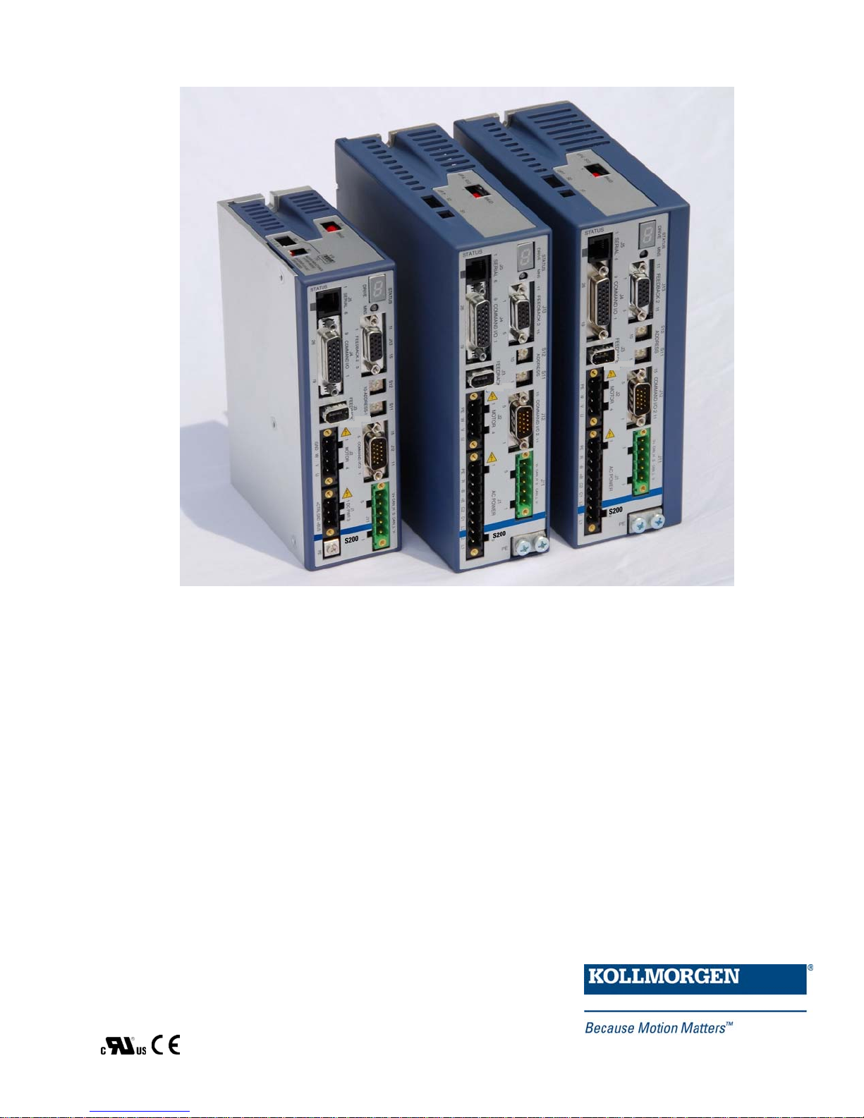
2.0 PRODUCT OVERVIEW
The S200 Position Node with CANopen/DeviceNetTM brings greater flexibility to the S200 drive platform
by adding profile generation and field bus capabilities. It also brings added I/O, Digital Oscilloscope
emulation, and the ability to use incremental encoder with commutation tracks (ComCoder) for motor
feedback.
The S200 Position Node brushless position node servo drives with CANopen push high performance
servo technology into lower power applications than was previously possible without having to
compromise on reliability or package size. Couple a S200 position node drive with an AKM servo motor
for a complete servo control solution designed to excel in applications such as semiconductor fabrication,
electronic assembly, packaging, medical, and woodworking equipment.
The S200 position node servo drives with CANopen communication are the first all digital industrial drives
with a velocity loop bandwidth up to 400 Hz offering unmatched system throughput and simplified tuning.
High resolution (24 bit) feedback and high performance 3-5 kHz current loop bandwidth provide smooth
motion and rapid start and stop action to optimize machine performance. Smart feedback and industry
leading high bandwidth deliver fast and accurate commissioning by eliminating the need for servo loop
tuning in most applications.
A separate "keep alive" power input allows rapid recovery from emergency stop conditions. Optically
isolated inputs/outputs, positive locking connectors and full fault protection promise long machine life and
immunity to accidental damage. A single motor power/feedback cable simplifies connectivity. All
connectors and LED status indicators are easily accessible from the front of the drive.
HIGHLIGHTS
DC or AC input voltage:
DC type: 20 V ... 90 V
AC type: 110 V ... 240 V, 1Ø or 3Ø, 50/60 Hz
Highest performance all digital servo in the industry
Operation and Setup via a PC using the S200 OC Tools setup software
Easy set up and tuning with Smart Feedback Device
Optimized performance with Kollmorgen AKM motors
Rugged optically isolated I/O
UL508C recognition, CE (EN50178, EN61800-3)
Very compact footprint
Full fault protection
Velocity, Position, and Electronic Gearing, Step and Direction control
Indexing - 180 unique motion tasks can be defined and initiated via the serial port, Can
Port, or discrete inputs
Jogs, Relative, Absolute, Simple Registration, and Home motion tasks can be easily
setup and executed
Individual motion tasks can be linked or blended with each other
Digital Oscilloscope Functions
Built-in CANopen / DeviceNet Communication bus
Incremental Encoder Input port allows ComCoder motor feedback for position loop
control.
S200 Position Node Installation Guide 4
Page 7

Product Overview 4/13/2012 Kollmorgen
INCREASED MACHINE THROUGHPUT & LONGER LIFE
Servo system performance is synonymous with machine throughput. The S200 POSITION NODE
family takes servo performance to new heights.
Industry-leading current loop bandwidth up to 5 kHz and velocity loop bandwidth up to
400 Hz means machine throughput can be increased by as much as 2 to 3 times.
Robust design including full fault protection, locking connectors and optical isolation
promise greater machine “up-time”.
Smooth motion, a benefit of sinusoidal current control and high resolution (24 bit)
feedback minimizes harsh torque disturbances that can cut short the life of mechanical
components.
Both the AC and the DC input drives are equipped with separate control power input to
speed recovery from “E-Stop” conditions.
CANopen Field Bus or DeviceNet communications
REDUCED ENGINEERING & SUPPORT TIME
Simplified tuning, friendly Graphical User Interface and shared components with Stepper
products.
Windows-based Graphical User Interface models the tree format found in Explorer so
learning is quick and easy.
Digital Oscilloscope emulator for easier setup.
Easy to debug with full fault diagnostics reduce engineering support time.
Field bus connectivity.
CE- / UL- CONFORMITY
The S200 position node with CANopen meets all relevant standards:
EMC Directive 89/336/EWG, standard used ENG61800-3
Low Voltage Directive 73/23/EWG, standard used 50178
UL / cUL 508C recognized
2.1 MODEL NUMBER SCHEME
S2 03 3 0 CN S - 002
Family
S2 - S200 Servo Family
Current Rating
- 1.5 A
02
4.5 A
03 - 3 A
9 A
06
- 6 A
18 A
Voltage
- 20-90 VDC
3
- 120 VAC doubler/240 VAC 1-phase
5
- 120/240 VAC
6
RMS
RMS
continuous,
RMS
peak
RMS
continuous,
RMS
RMS
continuous,
peak
peak
Electrical Option
- No Electrical Option
0
Customization - omit for standard drives
000 - 019 Reserved for factory use only
020 - 999
Feedback Support
S - SFD/Halls - Base Unit
SFD/Comcoder - CAN option card
Smart Feedback Device (SFD) - SynqNet Option Card
Sine encoder - SynqNet Option Card
EnDat 2.1 - SynqNet Option Card
Functionality
VT - Velocity/Torque modes
DN - Position Node w/DeviceNet Interface
CN SD - SynqNet option card w/ micro-D connectors
SR - SynqNet option card w/ standard RJ connectors
Reserved for customers only
Position Node w/CANOpen Interface
5 S200 Position Node Installation Guide
Page 8

Product Overview 4/13/2012 Kollmorgen
2.2 VALID DRIVE MODEL NUMBERS FOR THE S200 POSITION
NODE
DC Input Power Drive Models
S20330-CNS: 90 VDC, 3/9 A
S20330-DNS: 90 V
S20630-CNS: 90 V
S20630-DNS: 90 VDC, 6/18 A
, 3/9 A
DC
, 6/18 A
DC
AC Input Power Drive Models
S20250-CNS: 120VAC doubler/240VAC, 1 phase, 1.5/4.5 ARMS Base Unit, Profile Node with CanOpen
S20250-DNS: 120VAC doubler/240VAC, 1 phase, 1.5/4.5 ARMS Base Unit, Profile Node with DeviceNet
S20260-CNS: 120/240 VAC, 1/3-phase, 1.5/4.5 ARMS Base Unit, Profile Node with CanOpen
S20260-DNS: 120/240 VAC, 1/3-phase, 1.5/4.5 ARMS Base Unit, Profile Node with DeviceNet
S20350-CNS: 120VAC doubler/240VAC, 1 phase, 3/9 ARMS Base Unit, Profile Node with CanOpen
S20350-DNS: 120VAC doubler/240VAC, 1 phase, 3/9 ARMS Base Unit, Profile Node with DeviceNet
S20360-CNS: 120/240 VAC, 1/3-phase, 3/9 ARMS Base Unit, Profile Node with CanOpen
S20360-DNS: 120/240 VAC, 1/3-phase, 3/9 ARMS Base Unit, Profile Node with DeviceNet
S20650-CNS: 120VAC doubler/240VAC, 6/18 ARMS Base Unit, Profile Node with CanOpen
S20650-DNS: 120VAC doubler/240VAC, 6/18 ARMS Base Unit, Profile Node with DeviceNet
S20660-CNS: 120/240 VAC, 1/3-phase 6/18 ARMS Base Unit, Profile Node with CanOpen
S20660-DNS: 120/240 VAC, 1/3-phase 6/18 ARMS Base Unit, Profile Node with DeviceNet
S21260-CNS: 120/240 VAC, 1/3-phase 6/18 ARMS Base Unit, Profile Node with CanOpen
S21260-DNS: 120/240 VAC, 1/3-phase 6/18 ARMS Base Unit, Profile Node with DeviceNet
Base Unit, Profile Node with CanOpen
RMS
Base Unit, Profile Node with DeviceNet
RMS
Base Unit, Profile Node with CanOpen
RMS
Base Unit, Profile Node with DeviceNet
RMS
6 S200 Position Node Installation Guide
Page 9
Kollmorgen 4/13/2012 Specifications
3.0 SPECIFICATIONS
Unless otherwise specified, the specifications are worst case
limits and apply over the specified operating ambient
NOTE
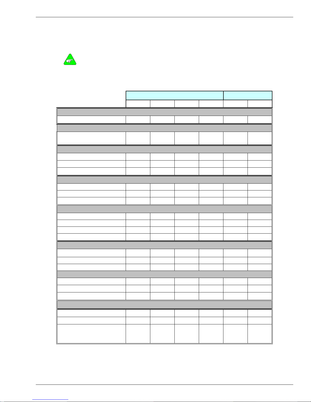
3.1 DRIVE FAMILY POWER
Drive Model Number S20260 S20360 S20660 S212660 S20330 S20630
Peak Output Current (A
(0 to 40°C) Ambient (A
Minimum Peak Current Time
(Starting from 0 amps) seconds 3 3 3 3 3 3
temperature and over the specified operating line voltage.
AC Input DC Input
)1
RMS
) 4.5 9 18 30 9 18
RMS
Continuous Output Current (A
0 to 30°C ambient (A
40° C ambient (A
50° C ambient (A
RMS
RMS
) 2.3 4.5 9 15 4.5 7.5
RMS
) 1.5 3 6 12 3 6
) 1 2 4 8 2 4
RMS
)2
Peak Output Power
240 VAC (VA), 3 phase 1500 3000 6000 10000 - -
120 VAC (VA), 1 phase 750 1500 2400 - - -
75 VDC (VA) - - - - 750 1500
Drive Continuous Output Power
240 VAC, 3 Phase (watts) 600 1100 2000 4000 - -
240 VAC, 1 Phase (watts) 500 900 1500 2500 - -
120 VAC, 1 Phase (watts) 250 450 - - - -
75 VDC (watts) - - - - 250 500
Continuous Motor Shaft Power at 3000 RPM (Nominal Bus – 10%)
0 to 30°C ambient (watts) 3-ph 300 750 1500 2500 - -
0 to 30°C ambient (watts) 1-ph 300 750 1300 2200 180 315
40° C ambient (watts) 200 500 1000 2000 125 250
RMS Line Current at Continuous Output Power
240 VAC 3 Phase (A
240 VAC 1 Phase (A
120 VAC 1 Phase (A
) 2.7 5 9 16 - -
RMS
) 3.4 6.5
RMS
) 3.4 6.5 12 (Note 3) - - -
RMS
12
(Note 3)
18 (Note 3) - -
+BUS Current – 75 VDC at Continuous Output Power3
Average (ADC) - - - - 3 6.7
Instantaneous Peak (A
Power Dissipation at 40°C
(watts)
P
CONT
) - - - - 12.7 25.5
PEAK
17 29 60 110 8 12
S200 Position Node Installation Guide 7
Page 10
Specifications 4/13/2012 Kollmorgen
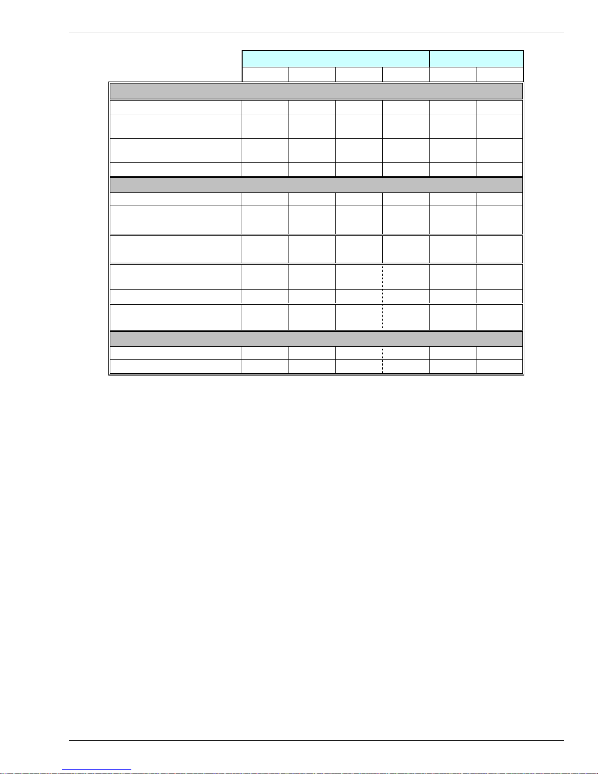
1
Drive Model Number: S20260 S20360 S20660 S212660 S20330 S20630
Shunt Regulator
Peak Power kW (500 ms) 4.4 at 36 6.4 at 25 10 at 15 10 at 15 - -
Cont. Power watts 440 at 36 640 at 25 1000 at
Maximum Regen Duty Cycle (%) 10 at 36 10 at 25 10 at 15 15 at 15 - -
Regen Value () 25 – 50 25 – 50 12 – 50 8 – 50 - -
Bus Capacitance Energy Absorption (joules)
340 VDC Nominal BUS 15.5 15.5 20 45 - -
75 VDC BUS with 4,000 µf -
(5 volt increase to 80 VDC)
Output Current Ripple Freq fS
(kHz)
- - -
20 20 20 >16 31.2 31.2
AC Input DC Input
15
1500 at
15
- -
1.5 1.5
Minimum Motor Inductance l-l
5 2.5 1.25 0.9 - -
(mH)
At 75 VDC - - - - 0.4 0.2
Maximum Motor Inductance l-l
300 150 75 45 30 15
(mH)
Maximum Motor Power Cable Length4
18 AWG cable (m) 50 50 25 - 50 25
14 AWG Cable (m) 50 50 50 50 50 50
2
3
4
Peak Output Current listed is for sine mode. In six-step mode, the peak output currents
are scaled to give the same output torque as in sine mode with a pure sinusoidal Back
EMF motor.
To convert A
For Operation above 40
At higher ambient temperatures (above 30
a thermally conductive surface to limit the heatsink temperature to less than 75
to A(0-pk), multiply A
RMS
o
C ambient: Derate linearly to 67% at 50o C .
* 1.414.
RMS
o
C) the S20360 drive needs to be mounted on
o
C.
Single phase operation of the S20660 requires derating of continuous output power to
avoid excessive AC line front-end currents.
See Appendix – Cables for voltage loss vs cable length.
8 S200 Position Node Installation Guide
Page 11

Specifications 4/13/2012 Kollmorgen
3.2 INPUT POWER SPECIFICATIONS
AC Control Power Supply
Input Voltage Range (RMS)
Ride Through Time for AC Line Drop
AC Motor Power Supply
Input Voltage Range (RMS) VAC 90 to 265
Phases 1 or 3
Transformer Suggested KVA 2 to 3
Maximum AC Line KVA1 100
1
Maximum AC Line is specified to limit the mains surges to the drive.
AC Bus Voltage and Faults
240 VAC Input Nominal Bus Voltage 320 VDC
120 VAC Input Nominal Bus Voltage 155 VDC
BUS Under voltage Fault Factory Default is None
BUS Over voltage (BusOV) Fault 407 VDC + 5%
BUS Regen Voltage = 0.974*BusOV = 397 VDC Nominal
85 VAC to 265 VAC single phase
47 to 63 Hz
120 VDC to 375 VDC
85 VAC 60 Hz > 0.78 60 Hz cycles
120 VAC 60 Hz > 3.3 60 Hz cycles
240 VAC 60 Hz >18.5 60 Hz cycles
AC Inrush Current & Fusing
Worse Case Inrush Peak Current at 240 VAC 140 A 0-p
Inrush pulse width 1.5 ms
Recommended Fusing Line Inputs
Type – 250 VAC Time Delay Fuse
240 VAC 3 Phase
(A
)
RMS
240 VAC 1 Phase
(A
)
RMS
120 VAC 1 Phase
(A
)
RMS
Control Power Applied to Drive Operational 1.25 seconds
S20260 S20360 S20660 S21260
FRN-R-5 FRN-R-8 FRNR-15 FRN-R-25
FRN-R-5 FRN-R-10 FRN-R-20 FRN-R-30
FRN-R-5 FRN-R-10 FRN-R-20
AC Power on Delay
-
9 S200 Position Node Installation Guide
Page 12

Specifications 4/13/2012 Kollmorgen
3.3 DC INPUT DRIVES - CONTROL AND POWER
DC Control Power
Control Voltage Range (VDC)
(J1-1 to J1-2)
Control Input power (watts)1 2 to 8
1
(20 watt min supply recommended) Refer to the DC Power Supply Section for detailed
application information and requirements.
+10 to +90
DC BUS Voltage and Faults
+BUS Voltage Range (VDC)
(J1-3 to J1-2)
+BUS Under voltage Fault +17 VDC nominal
+BUS Overvoltage Fault +91 VDC nominal
+20 to +90
DC Power On Delay
Control Power Applied to Drive
Operational
1.5 seconds
3.4 CONTROL LOOP PERFORMANCE
Motor Phase Current Waveform Pure sinusoidal or six-step, depending on
Motor Current Control
feedback device
(In Sine or six-step mode output torque = Motor KT*Drive IFB)
Motor Shaft Torque (Ignoring motor magnetic saturation)
Peak KT (N-m/A
Instantaneous KT (N-m/A
10 S200 Position Node Installation Guide
)*Drive Ipeak (A
RMS
)*IFB (A
RMS
RMS
)
RMS
)
Page 13

Specifications 4/13/2012 Kollmorgen
Current Loop Bandwidth
Maximum Bandwidth
AC Input Drive (kHz) 3
DC Input Drive (kHz) 5
Recommended Bandwidth
AC Input Drive (kHz) 2
DC Input Drive (kHz) 3
SFD Auto Set (kHz) AC &
DC
Bandwidth Variation For
Fixed Motor L
(% regulated independent of
bus volt)
Update Period (µs) 0.8
2
± 2.5
Recommended Max Motor Electrical Frequency (Hz)
AC Input Drive (Hz) 600
DC Input Drive (Hz) 900
Velocity Loop Performance
Maximum Stable Bandwidth (Hz with SFD) 400
Update Period (µs) 0.8
Range (rpm) 0 to 18,300
Command Resolution
< 0.001 rpm analog
0.558 rpm serial
Velocity Loop Compensation
KVP Range (Depends on Ipeak) 0.00044 to 0.106 (Ipeak)(1/rad/sec)
KVP Resolution (%) 10
KVI Range (Hz) 0 to > 22
KVI Resolution (%) 10
1
Range (Hz) 24.3 to > 46627
ARF0
1
ARF1
Range (Hz) 24.3 to > 46627
1
Values for ARF0, ARF1; from 3012 to 24873 Hz cannot be set.
Current Loop Specifications
- 3 dB Bandwidth (Hz) > 2000
- 45° Phase Lag (Hz) > 1000
11 S200 Position Node Installation Guide
Page 14

Specifications 4/13/2012 Kollmorgen
General Performance
Max Tracking Rate (rpm) > 48600
Max Recommended Rate (rpm) 25000
Max Tracking Acceleration (rpm/sec) > 16x106
Maximum Feedback Cable Length 50 m (164 ft)
3.5 MECHANICAL SPECIFICATIONS
S20330-CNS
S20330-DNS
S20630-CNS
S20630-DNS
Drive Height (A)
Drive Width (B)
Drive Depth1 (C)
Mounting Hardware
Drive Weight
Nominal
1
Depth measurement is for drive only. Add approximately 50.8 mm (2 in) to depth given in the table
to accommodate mating connectors and wire bend radius.
152.4 mm 152.4 mm 175.0 mm 175.0 mm 177.0 mm
6.00 in 6.00 in 6.9 in 6.90 in 6.97 in
28.7 mm 48.3 mm 54.8 mm 54.8 mm 76.2 mm
1.90 in 1.90 in 2.16 in 2.16 in 3.0 in
100.8 mm 100.8 mm 131.6 mm 131.6 mm 152 mm
3.97 in 3.97 in 5.18 in 5.18 in 5.98 in
M4 or #8 M4 or #8
0.40 kg 0.5 kg 0.77 kg 0.82 kg 1.5 kg
1.00lb 1.10 lb 1.69 lb 1.80 lb 3.2 lb
S20250-CNS
S20250-DNS
S20260-CNS
S20260-DNS
S20350-CNS
S20350-DNS
S20360-CNS
S20360-DNS
M4 or #8
S20650-CNS
S20650-DNS
S20660-CNS
S20660-DNS
M4 or #8 M4 or #8
S21260-CNS
S21260-DNS
Physical Dimensions and Specifications
3.6 I/O SPECIFICATIONS
Note: Analog command is not allowed in this product. Digital Velocity and Motion Task position
loop control is the only possibilities.
Maximum Range (volts) 0.5 – 4.5
Full Scale Tolerance (%)
Typical (Worse Case) +/- 1 (± 5)
Linearity (% Full Scale) <0.1
Monotonic to < 2
Offset (mV) < 100
Offset Drift (µV/°C typ.) 250
12 S200 Position Node Installation Guide
Analog Output (DacMon)
DACMON1, DACMON 2 (J4 14,15)
-16
Full Scale
Page 15

Specifications 4/13/2012 Kollmorgen
Quadrature Input CHA (J12-12, 13) CHB (J12-14,15)
Type RS-422/RS-485, TTL, Open Collector
Input Voltage +/- 200mV Differential
Input Termination Please see diagrams in manual
Maximum Line Frequency 625 kHz (corresponds to 2.5 MHz
General Purpose Digital Inputs
DINP1-4, DINP6-9 (J4 2-5 and J12 2-5)
Input Voltage ± ( 4.0 - 30.0) volts
Referenced to DINPCOM (J4-5)
Input Current 0.65 - 6.7 mA
Response Time 1.0 ms
DINP5/DINP10 (J4-10 & 11, J12-8 & 9)
Input Voltage 3.0 – 6.0 volts
Input Current 9.0 – 24.0 mA
DOUT1, DOUT2, DOUT3 (J4-6,7,8,9 J12-6,7)
Maximum Output Voltage - 0.30 to 30.0 volts
Clamp Voltage 33 volt ± 6%
Maximum Output Current 50 mA
On voltage 1.0 volts at 10 mA
1.2 volts at 50 mA
Response Time 1.0 ms
Quadrature Output (CHA- J4-19, 20 CHB- J4-21,22 CHZ- J4-17,18)
Type RS-422/RS-485
Quadrature Input
compatible
quadrature pulse rate)
General Purpose Outputs
Quadrature Outputs
Output Voltage 5.0 V Differential Output - Unloaded
Hysteresis 1/2 Quadrature Count corresponding to
Resolution
(With SFD)
13 S200 Position Node Installation Guide
Maximum Output Frequency 2.5 MHz
Marker Pulse Width Approximately 120 degrees
1/8 Encoder Line Count
125, 128, 500, 512, 1000, 1024, 2000,
2048, 2500, 4096, 5000, 8192, 10000,
16384, 20000, 32768
Page 16

Specifications 4/13/2012 Kollmorgen
3.7 ENVIRONMENTAL SPECIFICATIONS
Environmental Specifications
Operating Temperature (° C) – Full
Rating
Operating Temperature (° C) – Derated
Linearly Derate Continuous Current to
67% of 40
o
C Rating
Pollution Degree 2
Storage Temperature (° C) -20 to 70
Humidity (% non-condensing) 10 to 90
Altitude <1500 m (5000 feet)
0 to 40
40 – 50
3.8 SMART FEEDBACK DEVICE (SFD)
SFD (Smart Feedback Device)
Resolution/Rev (arc min) 24 bits = 0.0013
Repeatability (arc min RMS) < ± 2
-19
Rev = ± 0.04
Noise
No Filtering (arc min RMS) < 2
150 Hz Single Pole Filtered (arc min
< 2
RMS)
10 Hz Single Pole Filtered (arc min
< 2
-19
RMS)
DC Offset Temperature Drift < 2
-18
Absolute Accuracy
AKM1 (arc min) ± 2
AKM2 or 3, 4 (arc min) ± 2
-10.3
-11.1
Communications Update Period (µs) 51.2
-17
Rev RMS = 0.16
-18
Rev RMS = 0.08
Rev RMS = 0.02
Rev/° C = 0.08 arc min/° C
Rev = ±17
Rev = ±10
14 S200 Position Node Installation Guide
Page 17
Kollmorgen 4/13/2012 Accessories
4.0 ACCESSORIES
4.1 CABLES
Kollmorgen offers pre-made high quality cables for help in installation.
4.1.1 Motor and feedback cables
Motor and Feedback cable selections are covered in our Motioneering package to help select the correct sets
based on motor and drive size selection.
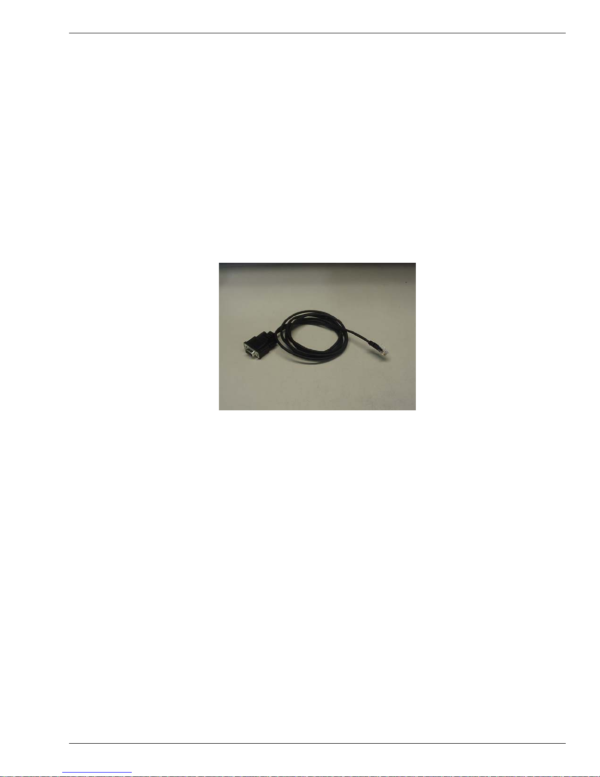
4.1.2 Serial Communications Cable
Kollmorgen offers a 6 ft serial communications cable designed to connect directly between the S200 Position
Node and standard PC 9 Pin communications port. Order Part Number P7S2-232-D.
S200 Position Node Installation Guide 15
Page 18
Accessories 4/13/2012 Kollmorgen
4.2 CONNECTOR KITS
Kollmorgen offers several connector kit options to help interface drive connections. Please note that there are
connector kits that are designed to interface to just the base unit drive and connector kits designed for the
auxiliary S200 Position Node auxiliary features. More than one connector kit may be required.
4.2.1 Base Unit Connector Kits
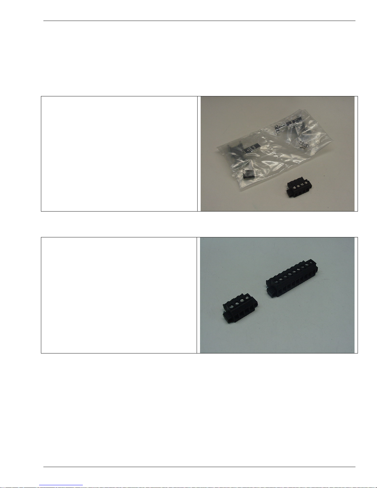
CK-S200-MF connector kit includes motor
and feedback connectors for all low power
base unit models. (JJ2 and J4).
This connector kit is useful in applications
and customers not using Kollmorgen Cables
Sets.
Applicable Drive Models:
S202x0-xNS, S20350-xNS, S20360-xNS,
S20660-xNS.
CK-S200-MP-AC connector kit includes
motor and power connectors for all low power
AC Input base unit models. (J1 and J2).
This connector kit is useful in applications
and customers not using Kollmorgen
Armature cables.
Applicable Drive Models:
S20250-xNS, S20260-xNS, S20350-xNS,
S20360-xNS, S20660-xNS.
16 S200 Position Node Installation Guide
Page 19
Accessories 4/13/2012 Kollmorgen
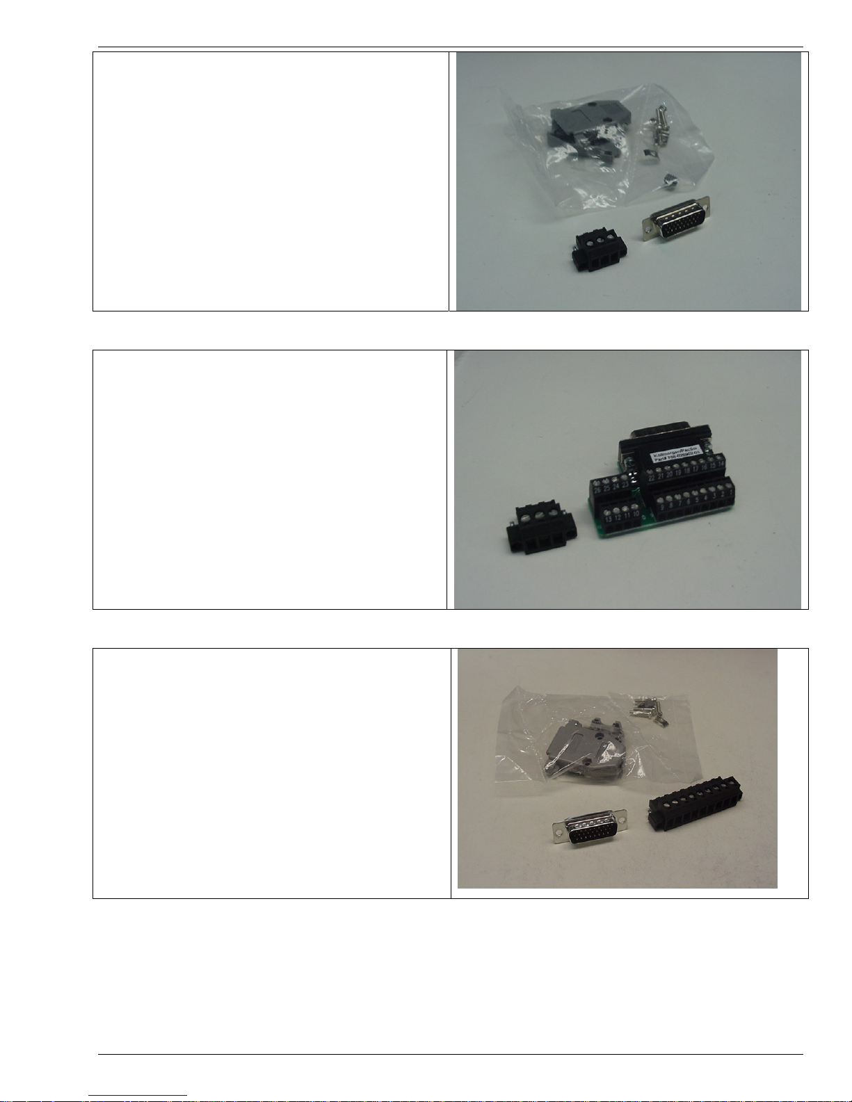
CK-S200-IP-DC connector kit includes power
and signal connectors for the S200 Base Unit
models. (J1 and J4).
This connector kit provides the auxiliary
connectors required when purchasing
Kollmorgen Cable sets.
Applicable Drive Models:
S20330-xNS, S20630-xNS
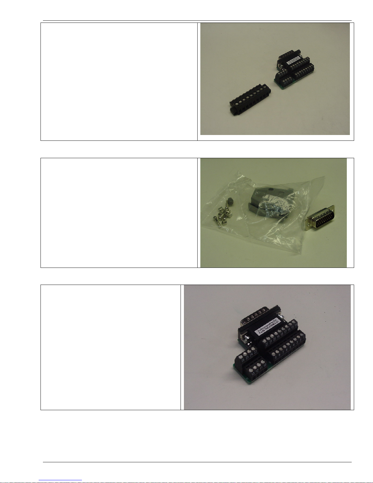
CK-S200-IP-DC-TB connector kit includes the
power connector and signal connector with
terminal block break out for the DC S200
Base Unit models. (J1 and J4).
This connector kit provides the auxiliary
connectors required when purchasing
Kollmorgen Cable sets when screw terminals
are preferred over soldering of J4.
Applicable Drive Models:
S20330-xNS, S20630-xNS
CK-S200-IN-AC connector kit includes both
the command signal connector, J4, and the
AC power connector, J1, for the low power
S200 Base Unit models. Solder cup
connector.
This connector kit provides the auxiliary
connectors required when purchasing
Kollmorgen Cable sets.
Applicable Drive Models:
S20250-xNS, S20260-xNS, S20350-xNS,
S20360-xNS, x20660-xNS.
17 S200 Position Node Installation Guide
Page 20
Accessories 4/13/2012 Kollmorgen
CK-S200-IN-AC-TB connector kit includes
both the command signal connector, J4, and
the AC power connector, J1, for the low
power S200 Base Unit models. Cage Clamp
connector kit.
This connector kit provides the auxiliary
connectors required when purchasing
Kollmorgen Cable sets where terminal screws
are preferred over soldering of J4.
Applicable Drive Models:
S20250-xNS, S20260-xNS, S20350-xNS,
S20360-xNS, x20660-xNS.
CK-S200-IN-AC connector kit includes
command signal connector, J4, for the S200
Base Unit models. Solder cup connector.
Applicable Drive Models:
All models
CK-S200-IN-AC-TB connector kit
includes command signal connector, J4,
for the S200 Base Unit models. Cage
clamp screw terminal connector.
Applicable Drive Models:
All models
18 S200 Position Node Installation Guide
Page 21
Accessories 4/13/2012 Kollmorgen
4.2.2 Position Node Connector Kits
CK-S200-CNDN connector kit includes:
command signal connector, J12, and the
encoder connector, J13 for the S200
Position Node auxiliary functions. Solder
cup connectors.
Applicable Drive Models:
All models with DNS or CNS suffix.
CK-S200-CNDN-TB connector kit includes:
command signal connector, J12, and the
encoder connector, J13 for the S200 Position
Node auxiliary functions. For applications
desiring screw terminal (cage clamp) over
soldered connections
Applicable Drive Models:
All models with DNS or CNS suffix.
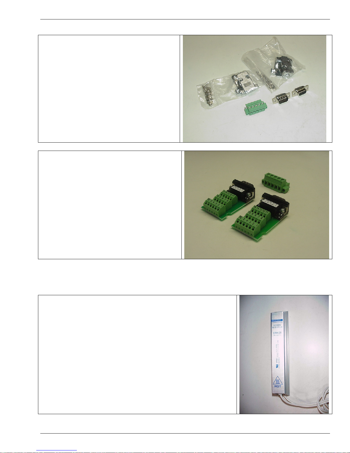
4.3 REGEN RESISTOR
Kollmorgen offers the ERH-26 fully enclosed, thermally
protected regen resistor rated at 26 ohms, 150 watts. The
resistor has connection leads and an integrated thermal switch
with fast-on type connectors. The thermal switch can be wired
into the user’s safety circuit. The ERH-26 is a UL Recognized
component.
19 S200 Position Node Installation Guide
Page 22

Accessories 4/13/2012 Kollmorgen
4.3 DIN RAIL TERMINAL BREAK OUTS
Soon to be offered. Ask service representative for latest availability.
4.4 OPERATOR INTERFACE TERMINALS
Kollmorgen does not currently offer direct purchase of Operator Interface Terminals other than with complete
systems. There are many units available in the general industrial equipment market place. Virtually any terminal
that has the ability to be configured for your application and has support for MODbus RTU with the ability to read
and write registers formatted for double registers (32 bit) in both long integer and floating point formats should be
compatible with the S200 Position Node product.
4.5 SYSTEMS CAPABILITIES
Kollmorgen offers a variety of pre-configured systems from component kits to pre-wired systems in NEMA 12
enclosures. Please consult your local Kollmorgen representative for details.
20 S200 Position Node Installation Guide
Page 23

Kollmorgen 4/13/2012 Installation
5.0 INSTALLATION
5.1 UNPACKING AND INSPECTING
Open the box and remove all the contents. Check to ensure there is no visible damage to any
of the equipment.
Use proper procedures when handling electronic
CAUTION
CAUTION
NOTE
components to avoid damage to equipment.
Remove all packing material and equipment from the
shipping container. Be aware that some connector kits and
other equipment pieces may be quite small and can be
accidentally discarded. Do not dispose of shipping materials
until the packing list has been checked.
Upon receipt of the equipment, inspect components to
ensure that no damage has occurred in shipment. If damage
is detected, notify the carrier immediately. Check all
shipping material for connector kits, documentation,
diskettes, CD-ROM, or other small pieces of equipment.
5.2 MOUNTING
The S200 drives are designed for operation in a cabinet using the following installation
instructions:
Mount the drives vertically inside a cabinet on a flat, solid, electrically conductive, mounting
surface connected to PE (protective earth ground) and capable of supporting the weight of the
unit.
Provide a good connection to PE. Remove the paint on the mounting surface over an area
extending at least 12 mm (0.5 in) from the mounting bolts to achieve good electrical connection
over a large area between the drive and grounded mounting surface.
Ensure the environment within the cabinet meets the requirements listed in the environmental
specifications table.
S200 Position Node Installation Guide 21
Page 24

Installation 4/13/2012 Kollmorgen
5.3 DIMENSIONS
Mounting Dimensions
S20330-CNS
S20330-DNS
S20630-CNS
Drive Dimensions
Drive Height (A) 152.4 mm 175.0 mm 175.0 mm 177.0 mm
6.00 in 6.90 in 6.90 in 6.97 In
Drive Width (B) 48.3 mm 54.8 mm 64.0 mm 76.2 mm
1.90 in 2.16 in 2.52 in 3.0 in
Drive Depth1 (C) 100.8 mm 131.6 mm 131.6 mm 152 mm
3.97 in 5.18 in 5.18 in 5.98 in
Clearance Requirements
Top and Bottom (D) 12.7 mm 25.4 mm 25.4 mm 25.4 mm
0.50 in 1.0 in 1.0 in 1.0 in
Side to Side (E) 12.7 mm 25.4 mm 25.4 mm 25.4 mm
0.50 in 1.0 in 1.0 in 1.0 in
Mounting Dimensions
Horizontal Mounting
Offset (F)
0.97 in 1.01 in 1.01 in 1.25 in
Vertical Mounting Offset
(G)
0.16 in 0.17 in 0.17 in 0.19 in
Vertical Mounting Height
(H)
5.68 in 6.67 in 6.67 in 6.67 in
Drive to Drive Mounting
(J)
2.40 in 3.16 in 3.52 in 4.0 in
Mounting Hardware
Drive Weight
S20630-DNS
24.6 mm 25.6 mm 25.6 mm 31.7 mm
4.1 mm 4.3 mm 4.3 mm 4.8 mm
144.3 mm 169.5 mm 169.5 mm 169.5 mm
60.96 mm 80.3 mm 89.4 mm 101.6 mm
M4 or #8 M4 or #8 M4 or #8 M4 or #8
0.5 kg 0.85 kg 0.5 kg 1.5 kg
1.10 lb 1.86 lb 1.10 lb 3.2 lb
S202x0-CNS
S202x0-DNS
S203x0-CNS
S203x0-DNS
S206x0-CNS
S206x0-DNS
S21260-CNS
S21260-CNS
1
Depth measurement is for drive only. Add approximately 50.8 mm (2 in) to depth given in
the table to accommodate mating connectors and wire bend radius.
22 S200 Position Node Installation Guide
Page 25

Installation 4/13/2012 Kollmorgen
5.4 MOUNTING OUTLINE
DEPTH
(C)
0.18 mm
4.57 in
RECOMMENDED MOUNTING
HARDWARE M4 OR #8
F 0.18 mm
TOP VIEW
WIDTH
(B)
4.57 in
HORIZONTAL
MOUNTING
OFFSET (F)
VERTICAL
MOUNTING
OFFSET (G)
FRONT VIEW
RIGHT SIDE VIEW
HEIGHT
(A)
VERTICAL
MOUNTING
HEIGHT (H)
VERTICAL
MOUNTING
OFFSET (G)
REAR VIEW
23 S200 Position Node Installation Guide
Page 26

Kollmorgen 4/13/2012 Wiring Diagrams
A
A
3
6.0 WIRING DIAGRAMS
The following diagrams present the electrical connection diagrams for High Power AC units, Low Power AC units,
and DC Power units.
6.1 LOW POWER AC DRIVE WIRING DIAGRAM
DINP COM
DINP1
DINP2
DINP3
DINP4
DOUT 1 -
DOUT 1
DOUT 2 -
DOUT 2 +
DINP5 +
DINP5 -
NC
I/O RET
DAC MON 1
DAC MON 2
I/O RET
CH Z OUT
CH Z OUT
CH A OUT
CH A OUT
CH B OUT
CH B OUT
I/O RET
NA CMD +
NA CMD -
I/O RET
DINP COM
DINP6
DINP7
DINP8
DINP9
DOUT 3 -
DOUT 3 +
DINP 10-
DINP10 +
5V Source
5V COM
CH A / Step
CH A / Step
CH B / DIR
CH B / DIR
J4
S200 Drive
1
2
3
4
5
6
7
8
9
10
11
12
13
14
15
16
17
18
19
20
21
22
23
24
25
26
1
2
3
4
5
6
7
8
9
10
11
12
13
14
15
J12
AC Input
Power
Models
S20260-xNS
S20360-xNS
S20660-xNS
J13
J3
J2
J1
J5
J11
1
2
3
4
5
6
7
8
9
10
11
12
13
14
15
1
2
3
4
5
6
1
2
3
4
1
2
3
4
5
6
7
8
9
1
4
5
6
1
2
4
5
CU
CV
CW
I/O RET
CH Z IN
CH Z IN
PTC
PTC RET
5V SOURCE
I/O RET
CH A IN
CH A IN
CH B IN
CH B IN
+5V
5V RET
SFD COM -
SFD COM+
PE
W
V
U
REGEN
BUS -
NC
BUS+
C1 CNTL
C2 CNTL
L3
L2
L1
NC
RX Data
I/O RET
I/O RET
Tx Data
NC
V-
CAN L
SHIELD
CAN H
V+
Protective Earth
Optional
Regen
RS 232
Configuration
Port
Optional
Encoder
Feedback
SFD
MOTOR
Optional
CanBus
Connection
120/240VAC Control
Power 47-63Hz Fused
120/240VAC Mains
47-63Hz Fused
S200 Position Node Installation Guide 24
Protective Earth
Page 27

Wiring Diagrams 4/13/2012 Kollmorgen
A
6.2 HIGH POWER AC WIRING DIAGRAM
DINP COM
DINP1
DINP2
DINP3
DINP4
DOUT 1 -
DOUT 1 +
DOUT 2 -
DOUT 2 +
DINP5 +
DINP5 -
NC
I/O RET
DAC MON 1
DAC MON 2
I/O RET
CH Z OUT
CH Z OUT
CH A OUT
CH A OUT
CH B OUT
CH B OUT
I/O RET
ANA CMD +
ANA CMD -
I/O RET
DINP COM
DINP6
DINP7
DINP8
DINP9
DOUT 3 -
DOUT 3 +
DINP 10-
DINP10 +
5V Source
5V COM
CH A / Step
CH A / Step
CH B / DIR
CH B / DIR
J4
1
2
3
4
5
6
7
8
9
10
11
12
13
14
15
16
17
18
19
20
21
22
23
24
25
26
J12
1
2
3
4
5
6
7
8
9
10
11
12
13
14
15
S200 Drive
C Input
Power
Model
S21260-xNS
J13
J3
TB1
J1
J5
J11
CU
1
CV
2
CW
3
4
I/O RET
5
CH Z IN
6
CH Z IN
7
PTC
PTC
9
5V
10
I/O
11
CH A IN
12
CH A IN
13
CH B IN
14
CH B IN
15
+5V
1
5V RET
2
SFD COM -
3
SFD COM+
4
5
6
PE
1
W
2
V
3
U
4
REGEN
5
BUS -
6
BUS+
7
L3
8
L2
9
L1
10
Protective Earth
1
C2 CNTL
2
C1 CNTL
3
NC
1
RX
2
I/O
3
I/O
4
Tx
5
NC
6
V+
1
CAN H
2
SHIELD
3
CAN L
4
V-
5
NC
Optional
Encoder
Feedback
SFD
MOTOR
Optional
Regen
Resistor
RS 232
Configuration
Port
120/240VAC Mains
47-63Hz Fused
120/240VAC Control
Power 47-63Hz Fused
25 S200 Position Node Installation Guide
Protective
Page 28

Wiring Diagrams 4/13/2012 Kollmorgen
A
A
p
p
6.3 DC MODELS DRIVE WIRING DIAGRAM
DINP COM
DINP1
DINP2
DINP3
DINP4
DOUT 1 -
DOUT 1 +
DOUT 2 -
DOUT 2 +
DINP5 +
DINP5 -
NC
I/O RET
DAC MON 1
DAC MON 2
I/O RET
CH Z OUT
CH Z OUT
CH A OUT
CH A OUT
CH B OUT
CH B OUT
I/O RET
NA CMD
NA CMD -
I/O RET
J4
S200 Drive
DC Input
Power
Models
J13
J3
J2
CU
CV
CW
I/O RET
CH Z IN
CH Z IN
PTC
PTC RET
5V SOURCE
I/O RET
CH A IN
CH A IN
CH B IN
CH B IN
+5V
5V RET
SFD COM -
SFD COM+
PE
W
V
U
Optional
Encoder
Feedback
DINP COM
DINP6
DINP7
DINP8
DINP9
DOUT 3 -
DOUT 3 +
DINP10-
DINP10 +
5V Source
5V COM
CH A / Ste
CH A / Ste
CH B / DIR
CH B / DIR
J12
J1
J5
J11
+ CNTL
BUS/CNTL GND
+ BUS
Note: J1 Pin 2 and all I/O RET pins are
tied together within the drive.
RX Data
I/O RET
I/O RET
Tx
NC
V+
CAN H
SHIELD
CAN L
V-
NC
Optional CAN
Bus Connection
RS 232
Configuration
Port
Main Power
20 – 90 V
Protective Earth
26 S200 Position Node Installation Guide
Page 29

Kollmorgen 4/13/2012 Connector Pinout And Discriptions
7.0 CONNECTOR PINOUT AND DISCRIPTIONS
The following section describes the user connections to the S200 Position Node by connector. The front part of
this section presents AC / DC input Power and Power Terminal wirings for various drive models. J1 and TB1 vary
according to the model. Please refer to the proper description for your model.
7.1 PE ALL DRIVE MODELS
Each S200 Position Node product has at least one screw terminal from its frame exposed to the front of the
product for customer wiring to Protective Earth (PE) ground. This connection should be made with heavy gage,
high strand count wire and a ring lug terminal directly back to the incoming earth ground distribution block. Power
should not be applied if this connection does not exist.
PE Ground Terminals
(TYPICAL)
S200 Position Node Installation Guide 27
Page 30

Connector Pinout And Descriptions 4/13/2012 Kollmorgen
7.2 J1 – LOW POWER AC INPUT POWER MODELS DRIVE POWER
Models S202x60-xNS, S203x0-xNS, S206x0-xNS
The S200 AC input drives are capable of direct line operation. All units are fully isolated and do not require
external isolation transformers. The inrush current on the connection to the line is internally limited to a safe level
for the drive. There are no voltage selection or ranging switches required to operate within the specified voltage
input ranges. Please note warnings that follow.
The S200 series drives are functionally compatible with all standard forms of three phase AC lines:
Grounded neutral WYE
Open-Delta Grounded Leg
TEE
19
Figure 7.1: J1 Connector view from front of drive
Pin Description
J1-1 PE (Protective Earth) – Must be tied back to central earth bar.
J1-2 REGEN – Connection for optional external regen resistor.
J1-3 -BUS DC – Internal DC Bus negative connection (Not normally used)
J1-4 +BUS – Internal DC Bus Positive Connection (Regen Resistor
Termination Point)
J1-5 C2 CTRL VAC – Logic control Power can be tied to 120 or 230Vac input
J1-6 C1 CTRL VAC – Logic Control Power can be tied to 120 or 230Vac input
J1-7 L3 240 VAC – Main Line for Bus power: Used for 3rd Phase
J1-8 L2 240/120 VAC – Main Line for Bus Power. Used for 1 or 3 Phase
J1-9 L1 240/120 VAC – Main Line. Used for 1 or 3 Phase
Please refer to the Specifications Section for appropriate rating and fusing requirements.
It is the customer’s responsibility to supply appropriate fuses or circuit
NOTE
28 S200 Position Node Installation Guide
breakers in the J1 AC drive power lines to comply with local electrical codes.
Page 31

Connector Pinout And Descriptions 4/13/2012 Kollmorgen
For maximum line droop tolerance connect logic power to 230Vac
NOTE
instead of 115Vac
After powering down the drive, monitor the BUS voltage by
connecting a meter from J1-4 (+BUS) to J1-3 (-BUS) to verify the
WARNING
internal BUS capacitors have discharged prior to working on the
drive.
The Regen input is not short circuit protected. The Regen
Resistance MUST be within specified ranges to prevent damage to
WARNING
the drive. For example, between 25 to 50 Ω for the S20260, S20360
drives or 15 to 50 Ω for the S20660.
CAUTION
To avoid damage to the connector and drive, NEVER plug or unplug J1
with power applied.
For single-phase systems Main Bus power must be wired to L1
and L2. Do not connect L3.
WARNING
Selected Regen Resistor must be able to handle constant 390Vdc
connection without risk of fire or must otherwise be thermally
WARNING
protected with an overload device.
J1 Mating Connector Information
Screw Terminal Connector:
12 – 24 AWG Wire Range, Phoenix MSTB2,5/9-STF-5,08-BK
OR Spring Cage Clamp Connector
12 – 24 AWG Wire Range, Phoenix FKC 2,5/9-SFT-5,08-BK
OR Crimp Connector
14-20 AWG Wire Range, Phoenix MSTBC 2,5/9-STZF-5,08-BK
Crimp Contact: 14-16 AWG Wire Range, Phoenix MSTBC-MT 1,5-2,5
Crimp Contact: 18-20 AWG Wire Range, Phoenix MSTBC-MT 0,5-1,0
Refer to www.phoenixcon.com.
29 S200 Position Node Installation Guide
Page 32

Connector Pinout And Descriptions 4/13/2012 Kollmorgen
7.3 J1 – AC INPUT CONTROL POWER HIGH POWER AC MODELS.
Models: S21260-xNS
NOTE
Pin Description
J1-1 PE (Protective Earth) – Must be tied back to central earth bar.
J1-2 C2 CTRL VAC – Logic control Power. Use 120 or 240Vac.
J1-3 C1 CTRL VAC – Logic Control Power. Use 120 or 240 Vac.
Please refer to the Specifications section for fusing and rating information.
It is the customer’s responsibility to supply appropriate fuses or circuit
breakers in the J1 AC drive power lines to comply with local electrical
codes.
For maximum line droop tolerance connect logic power to 230Vac instead of 115Vac
PE C2 C1
NOTE
CAUTION
To avoid damage to the connector and drive, NEVER plug or unplug J1
with power applied.
Mating Connector Information:
Screw Terminal Connector
12 – 24 AWG Wire Range, Phoenix MSTB2,5/3-STF-5,08-BK
OR Spring Cage Clamp Connector
12 – 24 AWG Wire Range, Phoenix FKC 2,5/3-SFT-5,08-BK
OR Crimp Connector
Crimp Shell: 14-20 AWG Wire Range, Phoenix MSTBC 2,5/3-STZF-5,08-BK
Crimp Contact: 14-16 AWG Wire Range, Phoenix MSTBC-MT 1,5-2,5
Crimp Contact: 18-20 AWG Wire Range, Phoenix MSTBC-MT 0,5-1,0
Refer to www.phoenixcon.com.
30 S200 Position Node Installation Guide
Page 33

Connector Pinout And Descriptions 4/13/2012 Kollmorgen
7.4 TB1: HIGH POWER AC POWER CONNECTIONS
Models: S21260-xNS
The S200 AC input drives are capable of direct line operation. All units are fully isolated and do not require
external isolation transformers. The inrush current on the connection to the line is internally limited to a safe level
for the drive. There are no voltage selection or ranging switches required to operate within the specified voltage
input ranges.
PE
W
V
U
Regen
-Bus
+Bus
1 PE Protective Earth (Motor Cable Shield Connection)
2 W Motor Output Phase W
3 V Motor Output Phase V
4 U Motor Output Phase U
5 Regen Optional Regen Resistor Connection (See Wiring Detail Section)
6 - Bus Main DC Bus – Output (Normally not connected)
7 + Bus Main DC Bus + Output (Normally connected with Optional Regen)
8 L3 Mains L3 Incoming Power Connection
9 L2 Mains L2 Incoming Power Connection
10 L1 Mains L1 Incoming Power Connection
Please refer to the Specifications section for fusing and rating information.
The S200 series drives are functionally compatible with all standard forms of
L3
three phase AC lines:
L2
L1
TB1 High Power AC Units Power Connection
Grounded neutral WYE
Open-Delta Grounded Leg
TEE
It is the customer’s responsibility to supply appropriate fuses or circuit
NOTE
31 S200 Position Node Installation Guide
breakers in the TB1 AC drive power lines to comply with local electrical codes.
Page 34

Connector Pinout And Descriptions 4/13/2012 Kollmorgen
For maximum line droop tolerance connect logic power to 230Vac
NOTE
WARNING
WARNING
WARNING
instead of 115Vac
After powering down the drive, monitor the BUS voltage by
connecting a meter from TB1-7 (+BUS) to TB1-6 (-BUS) to verify
the internal BUS capacitors have discharged prior to working on
the drive.
The Regen input is not short circuit protected. The Regen
Resistance MUST be within specified ranges to prevent damage to
the drive. 15 Ohms minimum resistance for the S21260-xNS.
Selected Regen Resistor must be able to handle constant 390Vdc
connection without risk of fire or must otherwise be thermally
protected with an overload device.
WARNING
Do not apply power or operate unit without the terminal block cover in
place.
Recommended Mating Connectors:
Spring Fork Lugs or M4 or #8 screws
Hollingsworth SS20948SF
Molex 19099-032
Or Equivalent
32 S200 Position Node Installation Guide
Page 35

Connector Pinout And Descriptions 4/13/2012 Kollmorgen
7.5 J1 – DC INPUT POWER MODELS DRIVE POWER CONNECTOR
The S200 DC input drives should be powered from power supplies with reinforced isolation.
On DC input drives, J1 is a 3 pin plugable connector.
3
1
CAUTION
NOTE
(J1 Connector view from front of drive).
J1: DC Units Control Power
Pin Description
J1-1 + CNTL (Logic Input Power 10-90Vdc less than 8 watts)
J1-2 BUS / CNTL GND (Logic and Bus Return)
J1-3 + DC BUS Input Power (20 to 90Vdcc)
Please refer to the Specifications section for fusing and rating information.
To avoid damage to the connector and drive, NEVER plug or unplug J1 with
power applied.
Refer to the DC Power Supply Requirements section for detailed
requirements selecting a compatible power supply.
Mating Connector Information
Screw Terminal Connector
12 – 24 AWG Wire Range, Phoenix MSTB2,5/3-STF-5,08-BK
OR Spring Cage Clamp Connector
12 – 24 AWG Wire Range, Phoenix FKC 2,5/3-SFT-5,08-BK
OR Crimp Connector
Crimp Shell: 14-20 AWG Wire Range, Phoenix MSTBC 2,5/3-STZF-5,08-BK
Crimp Contact: 14-16 AWG Wire Range, Phoenix MSTBC-MT 1,5-2,5
Crimp Contact: 18-20 AWG Wire Range, Phoenix MSTBC-MT 0,5-1,0
Refer to www.phoenixcon.com.
33 S200 Position Node Installation Guide
Page 36

Connector Pinout And Descriptions 4/13/2012 Kollmorgen
7.6 J2 – MOTOR POWER CONNECTOR
Applicable Models: All except S21260-xNS (See TB1, above for this model).
1
4
Pin Description
J2-1 PE (Chassis Ground) on S200 AC Input Drives
BUS/CTRL GND on S200 DC Input Drives
Intended for motor ground and motor cable shield connection.
J2-2 Motor Phase W Output
J2-3 Motor Phase V Output
J2-4 Motor Phase U Output
Please refer to the product specifications section for appropriate wire sizing information.
Mating Connector Information
Screw Terminal Connector: 12 – 24 AWG Wire Range, Phoenix MSTB2,5/4-STF-5,08-BK
OR
Spring Cage Clamp Connector: 12 – 24 AWG Wire Range, Phoenix FKC 2,5/4-SFT-5,08BK
OR
Crimp Connector
Crimp Shell: 14-20 AWG Wire Range, Phoenix MSTBC 2,5/4-STZF-5,08-BK
Crimp Contact: 14-16 AWG Wire Range, Phoenix MSTBC-MT 1,5-2,5
Crimp Contact: 18-20 AWG Wire Range, Phoenix MSTBC-MT 0,5-1,0
Refer to www.phoenixcon.com
(J2 Connector view from front of drive).
7.7 J3 – SFD FEEDBACK CONNECTOR
J3 is a 6-pin plugable IEEE 1394 style connector for the feedback device. Although this connector
mechanically accepts standard IEEE 1394 cables, it is electrically not an IEEE 1394 interface. The base
drive accepts either SFD (Smart Feedback Device) or Hall inputs.
Pins Description
12
34
56
(J3 Connector view from front of drive)
Mating Connector Information
IEEE1394, Firewire type, 2.0 mm plug set
22 AWG Max., Molex 55100-0600
Refer to www.molex.com for assembly instructions.
J3-1 +5 V Supply (200 mA) from drive
J3-2 +5 RTN 5V common
J3-3 SFD Communications -
J3-4 SFD Communications +
J3-5 NC
J3-6 NC
Shell Shield Connection
34 S200 Position Node Installation Guide
Page 37

Connector Pinout And Descriptions 4/13/2012 Kollmorgen
A
7.8 J4 – COMMAND I/O CONNECTOR
J4 is a 26-Position High Density D subminiature female connector.
9
18
26
19
1
10
(J4 Connector view from front of drive.)
Pin Description Pin Description
J4-1 DINP COM J4-14 DAC MON1
J4-2 DINP1 (Enable) J4-15 DAC MON2
J4-3 DINP2 J4-16 I/O RTN
J4-4 DINP3 J4-17 Encoder Output Channel Z
J4-5 DINP4 J4-18
Encoder Output Channel
J4-6 DOUT1- J4-19 Channel A Encoder Output
J4-7 DOUT1+ (Fault) J4-20
J4-8 DOUT2- J4-21 Channel B Encoder Output
J4-9 DOUT2+ (RUN) J4-22
J4-10 DINP 5+ J4-23 I/O RTN
J4-11 DIP5 – J4-24 Analog Command Input +
J4-12 Reserved J4-25 Analog Command Input -
J4-13 I/O RTN J4-26 I/O RTN
Channel
Encoder Output
Channel
B
Encoder Output
See Specifications Section for ratings and Wiring Information for wiring details.
Mating Connector Information
26-Pin Male High Density D-Sub with Back shell Kit
24 AWG Max., NorComp 180-026-102-001 – D-Sub Connector
NorComp 978-015-010-03-1 – Back shell Kit
Refer to www.norcomp.net.
Z
35 S200 Position Node Installation Guide
Page 38

Connector Pinout And Descriptions 4/13/2012 Kollmorgen
7.9 J5: SERIAL PORT CONNECTIONS
The S200 Position Node serial port is wired to connector J5 using RS232 physical layer protocol.
Pin Function
1 NC
2 Drive Receive RS232 Data
3 DC Common
4 DC Common
5 Drive Transmit RS232 Data
6 NC
Mating Connector Information
Standard RJ11 cord
Or Plug Example AMP 5-555426-3
1 6
J5 RS232 Serial Port Connections
7.10 J11 CAN BUS CONNECTIONS
J11 is a five-pin plugable connector to the CAN physical layer and is compliant with CANOpen
and the DeviceNet specification (less color code requirements).
Mating Connector
PHOENIX MSTB 2,5/ 5-STF-5,08 AU
Or Equivalent
Pin Description DeviceNet Color
J11-1 V-: Power of CAN Bus Black
J11-2 CAN_L: Comm Low Blue
J11-3 Shield Bare
J11-4 CAN_H: Comm High White
J11-5 V+: Power of CAN bus Red
15
36 S200 Position Node Installation Guide
Page 39

Connector Pinout And Descriptions 4/13/2012 Kollmorgen
7.11 J12 CONNECTOR
J12, Option Card General Purpose I/O is a 15-Position High Density D subminiature male
(plug) connector. 5 User-configurable discrete inputs, one user-configurable output, and
encoder (or step and direction) input channels are provided on this 15 Pin High Density D
socket connector. Detailed electrical information is given elsewhere in this document.
15 11
15
J12 Connector Pin Out
Pin Name Description
J12-1 DINP COM
J12-2 DINP6
J12-3 DINP7
J12-4 DINP8
J12-5 DINP9
J12-6 DOUT3 -
J12-7 DOUT3 +
J12-8 DINP10 - Digital Input 10 Cathode 5V nominal operation
J12-9 DINP10 + Digital Input 10 Anode: 5V Nominal operation
J12-10 +5VDC 5V Source from drive. Not to exceed 150mA
J12-11 I/O RTN 5V Common, Common for CMD Channels
J12-12 CMD CH A+ Gearing Input Channel A
J12-13 CMD CH A- Gearing Input Channel /A
J12-14 CMD CH B+ Gearing Input Channel B
J12-15 CMD CH B- Gearing Input Channel /B
Shell PE Shield Earth Connection for 360 Bond
Mating Connector Information
Solder cup, Metalized Shell
Mating Hood/Shell: Metalized
Common rail for DINP6-9
Digital Input 6 +/- 4 to 30V DC Operation
Digital Input 7 +/- 4 to 30V DC Operation
Digital Input 8 +/- 4 to 30V DC Operation
Digital Input 9 +/- 4 to 30V DC Operation
DOUT 3 Opto Isolator Emitter
DOUT3 Opto Isolator Collector
Norcomp 180-015-202-001 (or Equivalent)
Adam Tech DE09-HD-PN-SS (or Equivalent)
37 S200 Position Node Installation Guide
Page 40

Connector Pinout And Descriptions 4/13/2012 Kollmorgen
7.12 J13 ENCODER FEEDBACK CONNECTOR
J13, Option Card Optional Encoder Feedback is a 15-Position High Density D subminiature female (socket)
connector. Connector pin out is described below with more detailed electrical information is given elsewhere in
this document.
1511
15
J13 Connector Pin Out
Pin Name Description
J13-1 CU
J13-2 CV
J13-3 CW
J13-4 NC
J13-5 I/O RET
J13-6 Ch Z+
J13-7 CH ZJ13-8 PTC Motor Thermostat
J13-9 I/O RET
J13-10 5VDC
J13-11 I/O RET
J13-12 CH A+
J13-13 CH AJ13-14 CH B+
J13-15 CH BShell PE
Encoder system wiring and operation can require detailed information. Not all encoder manufactures or motors
that contain encoders are all wired to the same conventions. Detailed information is provided later in this manual.
Mating Connector Information
Solder cup, Metalized Shell
Adam Tech HDT-15-PD-RC (or Equivalent)
Mating Hood/Shell: Metalized
Adam Tech DE09-HD-PN-SS (or Equivalent)
Commutation track U (Hall U) Sourcing Input
Commutation track V (Hall V) Sourcing Input
Commutation track W (Hall W) Sourcing Input
No Connection
5V Common
Encoder Z Channel Input (Marker, Index) Diff High
Encoder /Z Channel Input (Marker, Index) Diff Low
Motor Thermostat Return to 5V Common
5V Encoder Source, 200mA max
5V Common
Encoder Channel A Input Differential High
Encoder Channel /A Input Differential Low
Encoder Channel B Input Differential High
Encoder Channel /B Input Differential Low
Shield Earth Connection for 360 Bond
38 S200 Position Node Installation Guide
Page 41

Kollmorgen 4/13/2012 DC Input Power Model Power Supply Requirements
8.0 DC INPUT POWER MODEL POWER SUPPLY
REQUIREMENTS
Applicable Models: S20330-xNS, S20630-xNS
DC Unit Bus Input Power Specifications
Bus Voltage (J1-3 to J1-2) + 20 VDC to + 90 VDC
BUS Supply Current 48 VDC BUS 75 VDC BUS
S20330 Continuous 3.3 ADC at 160 W 3.3 ADC at 250 W
Peak (3 sec) 10 ADC at 480 W 10 ADC at 750 W
S20630 Continuous 6.7 ADC at 320 W 6.7 ADC at 500 W
Peak (3 sec) 20 ADC at 960 W 20 ADC at 3,000 W
BUS Output Capacitance
(min)
S20330-xNS
S20630-xNS
48 VDC BUS 75 VDC BUS
4,000 µf, 63 V 2,000 µf, 100 V
8,000 µf, 63 V 4,000 µf, 100 V
Bus Supply
Characteristics
Wiring from BUS
Supply to Drive
Control Voltage
(J1-1 to J1-2)
Control Supply
Type
Control Supply
Wiring
The BUS Supply should have the following characteristics:
Must provide safety isolation from the power line
Can be regulated or unregulated
Bus Supply Return is connected to the Control Supply Return and I/O
RTN in the drive
Typical BUS Supply:
Unregulated, Isolating, step down transformer with secondary rectified
into capacitive filter
BUS Supply Return is connected to earth ground
10 ft maximum
16 AWG (minimum)
Twisted pair
Daisy chaining of multiple drives is acceptable
No contactor or switching in the BUS wiring
+ 10 VDC to +90 VDC
Isolating
Unregulated or Regulated
Common GND with bus supply and I/O RTN
20 watt supply or 1 amp short circuit
Wire control (J1-1) to bus (J1-3)
or
Wire control (J1-1) to separate supply to preserve status and fault
information. (+ 10 VDC to + 30 VDC supply can be shared by Control
and I/O)
S200 Position Node Installation Guide 39
Page 42

DC Input Power Model Power Supply Requirements 4/13/2012 Kollmorgen
Control Supply
Current
Bus Voltage
20 to 110 mA at 75 VDC
60 to 330 mA at 24 VDC
125 to 660 mA at 12 VDC
Bus voltage outside the operating range (20 to 90 V) causes an undervoltage or over-voltage fault. Under-voltage and over-voltage faults self
clear when the fault condition clears.
Do Not allow the Bus Voltage to exceed
+ 90 VDC. This causes damage to the
NOTE
drive.
Target design center voltage for unregulated supply is + 70 to + 75 VDC.
This provides 15 to 20 VDC margin for line tolerance, transformer
regulation, and regen pump up. Design center voltage for a regulated
supply can be up to + 80 VDC.
8.1 CONTROL VOLTAGE
The control voltage range for normal operation is + 10 VDC to + 90 VDC. The control voltage
can either be wired to the bus voltage so one supply can power the drive, or from a separate
supply. Separately powering the control from the bus allows the bus to be powered down for
safety while drive status and fault information remain available. A single + 10 VDC to + 30 VDC
supply can be shared by Control and I/O.
NOTE
8.2 GROUNDING
Provide safety isolation with the external bus and control supplies from the power line.
NOTE
The Ctrl and Bus voltages and non-opto coupled I/O grounds (I/O RTN) are tied together
inside the drive. The Ctrl and Bus power supplies share a ground pin (Bus/Ctrl Gnd). Join and
connect to the negative terminals of the Ctrl and Bus power supplies. The I/O RTNs are
normally connected to the signal ground of the system. (Some of the I/O is opto coupled and
have separate returns. Thoroughly review this document for details.)
Earth the power supply negative terminal somewhere in the cabinet. Also earth the chassis. In
normal operation, there should be no significant voltage between earth and the Bus/Ctrl Gnd
and I/O RTNs.
NOTE
Do Not allow the Control Voltage to exceed + 90 VDC as it can damage the
drive.
The drive cannot be powered from an electrically Hot supply as it does not
contain an isolation barrier.
The maximum voltage allowed between Bus/Ctrl Gnd and chassis is 100
VDC.
8.3 BUS CAPACITANCE
There is a minimum requirement on the output capacitance of the bus power supply for the DC
input S200. This capacitor is needed to absorb energy during motor deceleration and motor
disable and to help provide energy during motor acceleration. For multiple S200 drives
operated from one supply the recommendation is to increase the capacitance according to the
number of drives. For example, for four 6 A / 18 A
40 S200 Position Node Installation Guide
DC S200 drives powered from one 75
RMS
Page 43

DC Input Power Model Power Supply Requirements 4/13/2012 Kollmorgen
VDC supply the recommended minimum bus output capacitance of the supply is 4 x 4,000 µf =
16,000 µf. Bus capacitor voltage rating should be 100 V. Bus capacitor type is aluminum
electrolytic.
8.4 BUS SWITCHING AND FUSING
Do not put E-Stop switches or contactors between the drive bus pin (J1-3) and the power
supply bus capacitor. There is a risk of damage to the drive if the bus is disconnected from the
power supply capacitor when the drive is enabled. The motor does not need to be rotating to
regenerate energy. The motor windings store magnetic energy that regenerates back to the
supply when the drive is disabled.
E-stop switches can safely be located in series with the primary winding of a step down
transformer. If individual axis E-Stop switches are required, connect a local (unswitched)
capacitor (1,000 µf, 100 V) across the drive bus terminals (J1-3 to J1-2).
If the buses of individual drives are to be fused, select the fuse type and rating for high margin.
S20630 (6 amp) S20330 (3 amp)
15 A, Slo-Blo (Bussmann MDA-15) 7 A, Slo-Blo (Bussmann MDA-7)
41 S200 Position Node Installation Guide
Page 44

Kollmorgen 4/13/2012 Detailed Wiring Information
9.0 DETAILED WIRING INFORMATION
Connector pin-out detail is provided in the prior section of this manual. This section deals with the details of the
internal operation of the drive connections. This information is provided to allow the system designer insight
sufficient to create a robust system wiring plan.
9.1 DEFINITIONS DISCUSSION
Bred from the older days of PLCs and the newer days of digital logic some words have become standard in some
industries. Some terms are described here to make this document easier to understand:
Common Rail: Common rail is simply a term meaning that more than one input (or output) has one terminal of its
device tied to the other inputs (or outputs). An example of a common rail is shown below
Figure 8.1 Common Rail Illustration
In Figure 8.1 each input is represented by the LED. Each input has a common connection (Anode) to the positive
side of the I/O power source. This is what is referred to as a common rail. It is also allowable to modify this circuit
where each anode goes to the switch and each resistor is tied to the negative side of the I/O supply.
Sourcing Input: A sourcing input is an input that must be taken to ground to operate. (It SOURCES current). The
above figure shows discrete inputs arranged for sourcing. These are used with sinking output device such as
Open Collector drivers. Some manufacturers of driving devices refer to sinking outputs as ‘NPN’ devices after
then name of the driving device transistor type.
Sinking Input: A sinking input has the opposite arrangement of souring inputs where a current-to-ground must be
supplied to the input. (Sinking current to ground). These are used with sourcing output devices. Some
manufacturers of driving devices refer to sinking outputs as ‘PNP’ devices after then name of the driving device
transistor type.
:
9.2 PE EARTH GROUND CONNECTIONS
It has been noted throughout this manual that a connection to earth ground is required. Multiple connections may
be required. The connection to earth ground can affect safety and electrical noise immunity and emissions. The
purpose of this text is to alert the user to the requirement of the earth ground connection. When connecting earth
grounds it is often required to have a connection that cannot come undone so ring lugs to the frame is highly
recommended. Each earth ground wire should go directly back to the central earth ground block in the cabinet; do
not daisy-chain the connections. Large gage wires consisting of many fine strands of wire are superior to other
types for conducting high frequency noise and the use of high strand count wire is recommended.
9.3 SERIAL PORT WIRING
Connector J5 is the RS232 Serial Port. Kollmorgen offers a pre-made serial communications cable P/N P7S2232-D for direct connect to a computers 9-pin serial communications port. The following information is supplied for
applications choosing to not use this cable.
While some computers may vary in the actual pin-out most computers have followed standardizing these
connections. The following diagrams are provided for standard 9 pin and 25 pin Subminiature D-type connectors
provided on most computers. Many HMI/OIT manufactures have chosen to swap pins to allow the cable to be
made pin-for-pin. Always consult the manufacture’s recommendations before wiring these types of products.
S200 Position Node Installation Guide 42
Page 45

Detailed Wiring Informati on 4/13/2012 Kollmorgen
To PC
9 Pin Female
To PC
25 Pin Female
2
3
5
3
2
7
5
To J5
2
on Drive
3
5
To J5
2
on Drive
3
9.4 WIRING DISCRETE DIGITAL INPUTS
The discrete digital inputs are DINP1-10. This section discusses wiring of inputs DINP1-4, and 6-9. Digital inputs
5 and 10 are different than the rest and will be covered in the next section.
DINP1-4 and 6-9 are available on J4 and J12 and are identical sets of 4 inputs on each connector. These inputs
are bipolar common rail inputs rated for operation from 4 to 30 Vdc. Common rail means that each one of the setof-four have one pin each tied together to come out of the drive as one pin. Bipolar means that the input will
function regardless of the connection polarity.
Input DINP1 is a dedicated hardware enable and it must be asserted to get the drive to enable the motor. DINP2DINP10 are user configurable but have default assignments as listed in the S200 Position Node User’s Guide.
Inputs can be wired for sourcing or sinking devices.
9.4.1 Typical wiring with sinking switches:
Customer’s Power Supply
4 to 30Vdc
+
-
J4-1
(J12-1)
J4-2
(J12-2)
J4-3
(J12-3)
Customer’s Switching
(May be Solid State –
Typically Open Collector)
J4-4
(J12-4)
J4-5
(J12-5)
Field Wiring
In the above diagram the switches conduct electrical current through the S200 Position Node inputs to ground.
Many interface devices encountered in machine control use solid-state switches that are commonly NPN
transistors.
S200 Position Node Internal Equiv
Circuits
-
DINP1
(Enable)
(DINP6)
DINP2
(DINP7)
DINP3
(DINP8)
DINP4
(DINP9)
43 S200 Position Node Installation Guide
Page 46

Detailed Wiring Informati on 4/13/2012 Kollmorgen
9.4.2 Typical Wiring with Sourcing Switches
Customer’s Power Supply
4 to 30Vdc
-
+
J4-1
(J12-1)
J4-2
(J12-2)
J4-3
(J12-3)
Customer’s Switching
(May be Solid State)
J4-4
(J12-4)
Field Wiring
J4-5
(J12-5)
The above diagram shows typical wiring for Sourcing switches. The Switches supply the source of current through
the S200 Position Node input. These devices may be solid state and are sometimes called PNP devices.
Current drain for the inputs is identified in the following table.
Input Voltage (±) Input Current (±)
4.0 volts 0.65 mA
5.0 volts 0.95 mA
12 volts 2.5 mA
24 volts 5.3 mA
30 volts 6.7 mA
S200 Position Node Internal Equiv
Circuits
-
DINP1
(Enable)
(DINP6)
DINP2
(DINP7)
DINP3
(DINP8)
DINP4
(DINP9)
9.4.3 Wiring DINP5 and DINP10
As noted DINP5 and DINP10 are high speed opto-isolated input devices that do not have a connection to a
common rail. They are designed for 5 volt operation and the polarity of the power supply used is critical for
functionality. Not having a common rail connection the inputs can be wired for sourcing or sinking according to the
need of the application.
44 S200 Position Node Installation Guide
Customer’s Power Supply
5Vdc
Field Wiring
J4-10
(J12-10)
J4-11
(J12-11)
S200 Position
-
-
DINP5
(DINP10)
Page 47

Detailed Wiring Informati on 4/13/2012 Kollmorgen
For systems desiring to use input voltages exceeding the 5V rating for DINP5 and DINP10 an external current
limiting resistor must be used. The resistor should be in series with the input line. The following table indicates the
recommended resistor values.
Supply Voltage Resistor Value
3-6V No Resistor
12V 470 Ohm ¼ Watt
24V 1200 Ohm, ½ Watt
9.5 WIRING DISCRETE DIGITAL OUTPUTS
The S200 Position Node has 3 outputs: Fault, /Run, and one user-configurable. These outputs can handle no
more that 50mA current and no higher than 30Vdc circuit design. Each output is ‘uncommitted’. That term simply
means that both pins of each output are user-wired, not tied to a common rail. The purpose for this is to allow
greater flexibility in the end application. The outputs are solid-state transistors and are polarity sensitive: Proper
polarity must be observed. All three outputs are electrically identical.
Fault Output: The fault output is a dedicated normally closed output for user use. This means that the output is in
the on state when no fault is present. If a fault is detected the S200 Position Node will turn this output off. This
method is considered fail-safe in that many failure modes of this circuit will cause the host to detect a fault.
Run Output: The Run output is a dedicated normally closed output for user use. This means that the output is in
the on state when the S200 POSITION NODE is ready to run. Internally, the Run output is conceptually
equivalent to the Power Stage Enable line. If the power stage is enabled the output will be on. If the user disables
the drive, ether by hardware or software disable, or if the drive detects a fault and shuts down the power stage
then the output will open. This logic is typical of systems requiring holding brakes.
User Configurable Output: The S200 Position Node User’s Guide has information regarding the function of this
output.
Typical wiring configurations of any of these outputs are either direct logic connection back to a host controller or
to a relay. The following diagrams show typical wiring configurations.
WARNING
Connection of any inductive load, such as a relay coil, must use
diode suppression across the coil to prevent excessive voltage
kick-back at turn off.
Outputs are not overload protected. Do not exceed maximum
rated current.
Wiring Discrete Output to LED or Opto Isolator
Customer’s Power Supply
Resistor limiting
current to <50mA
S200 Position Node Internal
Field Wiring
-
45 S200 Position Node Installation Guide
Page 48

Detailed Wiring Informati on 4/13/2012 Kollmorgen
Customer’s Power Supply
Relay
Coil
S200 Position
Field Wiring
-
The above diagrams are applicable to systems implementing a solid-state load or relay
connected to an S200 Position Node output. Load LED and resistor or relay coil (reverse
diode) can be in ether leg of the power circuit.
9.6 USING THE DAC MONITORS
The S200 Position Node has two analog outputs for use by the customer at J4. Each has a list of possible
assignments and a default value as listed in the S200 Position Node User’s Guide. The DAC (Digital to Analog
Converters) are OPAMP (Operational Amplifier) outputs and care should be taken to assure noise-free signal
reception. The range of each monitor is 0.5Vdc to 4.5Vdc and has an internal source impedance of 2k ohms. This
internal impedance limits to short circuit current to 2mA and can be a source of signal attenuation if too much load
is drawn from these outputs. These outputs are intended to feed instrumentation such as an Analog input to a
host or an oscilloscope for function monitoring. Each DAC Monitor output supplies a single-ended output voltage
referenced to the I/O RTN pin. The use of shielded, twisted pair wire is recommended if these circuits are to be
wired to another device. The shield should be tied to the frame of J4 at the drive and the frame of the receiving
equipment.
9.7 WIRING ENCODER OUTPUT SIGNALS
Available at J4 for the customer’s use are encoder equivalent output signals. These signals provide incremental
encoder performance for the motor driven by the S200 Position Node and can be used by a host controller or
monitor. The signals are differential driven and are RS-485 / RS 422 compliant. The use of terminating resistors at
the receiving end (120 ohm) is recommended. The output drivers are short-circuit protected. The encoder
resolution can be adjusted by switch S1 at the top of the drive or by the S200 OC Tools software. Refer to the
S200 User’s Guide for setup information on the resolution of the output.
Wiring for these signals should be done with individually twisted/shielded pairs. Shields should be tied at the
frame of J4 at the S200 Position Node and at the frame of the receiving equipment. An additional wire to tie the
two system’s DC common together is highly recommended to prevent damage from ground-shift spikes. Tie the
connection to any I/O RTN pin on J4 at the S200 PN.
9.8 MOTOR WIRING
Good motor wiring practice is a must when applying any PWM controlled servo motor drive to the motor. The
S200 PN uses PWM voltage control to the motor. The frequency of the PWM may vary according to the model
number. PWM systems switch high voltage at very fast rates. This voltage switching creates fast edged on the
voltage signals traveling down the motor cable to the servomotor. This switching voltage can couple capacitively
in both the cable and the motor creating high frequency current flows that must be controlled. Kollmorgen offers
highly engineered cables to provide the best control of these signals.
Should the user decide to wire the motor there are a few important recommendations that should be followed:
46 S200 Position Node Installation Guide
Page 49

Detailed Wiring Informati on 4/13/2012 Kollmorgen
The motor cable must have a separate conductor that carries the motor frame back to the S200 PN’s PE terminal
designated for the motor cable.
Chosen cable should be at least 600V rated and should have relatively low capacitance. The motor cable should
have >90% shield coverage and the shield should be of braided design, not foil. The cable shield should
terminate, along with the motor case wire, to the S200 Position Node’s PE terminal designated for the motor cable
at the drive end and to the connector housing at the motor with a 360-degree bond attachment.
Motor cables should be uninterrupted from the drive to the motor. In case where this is not practical the motor
cable connection should be made with a connector type that allows 360 degree shield coverage so that the cable
shield appears uninterrupted.
Appendix A has more information on installation practices that allow for trouble-free installation. Please read that
section before proceeding.
9.9 REGEN RESISTOR WIRING
Applicable Models: All AC Input units.
Many applications do not require the use of a regen resistor. Kollmorgen’s Motioneering software can predict the
need for a regen resistor. There is also an application note on the Kollmorgen website (www.Kollmorgen.com
providing the equations to calculate the regenerative levels. Nuisance over voltage tripping is the symptom
indicating the need for a regen resistor. Kollmorgen offers the ERH-26 regen resistor compatible for use meeting
all the requirements of the S200 Position Node product line.
Connection for an optional regeneration power resistor to absorb regenerated energy from the motor is provided
on each S200 Position Node. If the ERH-26 is not used, then the user should choose a wire-wound resistor with
1500 V
specified for the given drive. The power rating of the regen resistor depends on the amount of regenerated energy
that needs to be dissipated. In many applications there is little need for an aggressive low-ohm value resistor. The
chosen resistor must be self-protecting against overheating failure. This can be done any number of ways
including; thermal snap action fuse protection, a series thermal overload heater relay, or with a resistor value that
can limit the maximum wattage to the rating of the resistor. Any protection using contacts would have the switch
wired into a safety circuit that shut down the system in the event of a resistor over temperature to prevent a fire
hazard.
isolation between terminals and case. The regen resistor must not have a lower ohm value than
RMS
Wiring to the regen resistor should be short and the leads should be twisted together. Although never required, in
systems with sensitive electronics it is not uncommon to shield these wires with a braided cable with shields tied
to earth at both ends. Thermal overload protection is wired into the machine safety circuit such that it causes a
machine shut-down upon sensing excessive regen resistor temperatures.
)
9.10 STEP AND DIRECTION OR ELECTRONIC GEARING WIRING
The S200 Position Node has the ability to accept position commands from and external source in the form of
pulses. Typical systems use one of two devices for this command: incremental encoder signals or step (pulse)
and direction signals. The S200 Position Node electrical input circuits for these signals uses differential line
receivers and resistor biasing to allow use with differential line transmitters, open collector, or TTL driver circuits.
The circuit arrangement is shown in the following diagrams. Due to this circuit design it is very important to tie the
DC Commons of the two systems together.
Incremental encoder signals are typical of systems that are used as a gear-follower, some times called master or
line-shaft. Details of how these systems work can be found in the S200 Position Node User’s Guide. The basics
are that an encoder signal (A/B differential) is wired into the S200 Position Node’s J12 connector. These signals
are translated into quadrature pulses that increment or decrement the internal position loop command register,
subject to acceleration and deceleration limits. The S200 Position Node has no use for an encoder Z (marker or
index) channel for these applications. The source of these signals can be ether another controller with encoder
outputs or a stand-alone incremental encoder. A 5V supply is available at J12 as a power source for the standalone encoder. Typical interconnect is presented below.
47 S200 Position Node Installation Guide
Page 50

Detailed Wiring Informati on 4/13/2012 Kollmorgen
Ω
Ω
Ω
Ω
Encoder
J12-10
J12-12
J12-13
J12-14
J12-15
6.4k
225
S200 Position
5Vdc
x4
x4
Field Wiring
J12-11
5.9k Ωx4
100pF x4
For systems desiring TTL interface, TTL outputs would be tied to A and B while leaving /A and /B not connected.
The DC Commons must be tied together. Open collector interface is shown below.
Controller Step Output
Controller Direction Output
Field Wiring
Step
These transistors are
the controller’s Output
(Open Collector
Driver)
J12-10
J12-12
J12-13
J12-14
J12-15
J12-11
6.4k
225
5.9k Ωx4
S200 Position
5Vdc
x4
x4
100pF x4
The above circuit shows a generic interface using open collector drives to drive the encoder input signals of the
S200 Position Node. Several manufacturers of PLC with step and direction output use this method. Note the
required use of pull up resistors.
9.11 ENCODER MOTOR FEEDBACK
The following diagrams indicate how to wire an encoder feedback to the S200 Position Node
drive. The information provided pertains to Kollmorgen AKM Series motors. Other motors or
encoder manufacturers may use different conventions when naming signals. Kollmorgen
cannot be responsible for the differences but a phasing diagram and some explanations are
provided to help the user determine the proper wiring and setup for other component suppliers.
48 S200 Position Node Installation Guide
Page 51

Detailed Wiring Informati on 4/13/2012 Kollmorgen
The AKM motor wiring is provided below in both schematic and tabular form.
J13
12
13
14
15
6
7
10
5
8
9
1
2
3
NC
CH
CH
CH
CH
12
CH Z
CH
+5V
I/ORET
PTC
PTC
CU
CV
CW
I/O RET
AKM Motor
Encoder
AKM ‘C’ OptionSignal
Connector Pin
Number
Motor Wire
Color
AKM ‘M’
Option
Connector
Pin #
Description
Name
Drive Pin#
On J13
CU 1 15 BRN 15 Open Collector U Channel commutation
input to drive.
CV 2 16 GRY 16 Open Collector V Channel commutation
input to drive.
CW 3 17 WHT 17 Open Collector W Channel commutation
input to drive.
NC 4 - - - No connection
I/O RET 5 7 BLK 7 Signal common for 5V supply from drive
Z 6 5 VIO 5 Z channel (Also called Marker or Index)
to drive.
/Z 7 6 VIO/BLK 6 Z Complement (Differential driver) to
drive.
PTC 8 8 ORG 8 Motor Thermostat (Active Open)
PTC RET 9 9 ORG/BLK 9 Motor Thermostat Return (Common)
+5VDC 10 10 RED 10 +5V Source from drive for encoder
power.
I/O RTN 11 - - Additional 5V source return common.
A+ 12 3 BLU 3 A Data Channel Input to drive.
A- 13 4 BLU/BLK 4 A Channel complement (Differential
driver) to drive.
B+ 14 1 GRN 1 B Data Channel Input to drive.
B- 15 2 GRN/BLK 2 B Channel complement (Differential
driver) to drive.
Case Case - Shell 18 Cable shield connections. Normally
connects the back shell on both ends of
the cables. (Molex does not have a back
shell so pin 18 is used).
49 S200 Position Node Installation Guide
Page 52

Detailed Wiring Informati on 4/13/2012 Kollmorgen
Motors using incremental encoders used with the S200 Position Node must provide hall emulation commutation
tracks in with open collector drive circuits. The alignment of the commutation tracks to the motor’s back EMF
(magnetic alignment) is critical. The following phase diagram will indicate the proper alignment. S200 OC Tools
and the S200 PN support a phase offset adjustment when the hall tracks cannot be properly aligned but the
actual determination of the correct offset is by trial and error. The basic procedure is not discussed other than to
say that the phase is correct when the motor’s actual output torque is balanced in both directions for a given
command.
The following phasing diagram can be helpful when using motors other than Kollmorgen’s AKM Series with
encoder feedback.
50 S200 Position Node Installation Guide
Page 53

Detailed Wiring Informati on 4/13/2012 Kollmorgen
51 S200 Position Node Installation Guide
Page 54

Kollmorgen 4/13/2012 System Startup
10.0 SYSTEM STARTUP
The companion S200 Position Node User’s guide has information pertaining to installation and use of the User
Interface Program (GUI) called S200 OC Tools. The following startup recommendations assume that the user has
the GUI installed on the computer for test and setup and that it is appropriately connected via RS232
communications.
10.1 WIRING CHECKS
Before applying any power please double check all wiring for accuracy and quality. Wiring should be done to local
and national wiring standards. In addition please ensure the following:
Earth ground must be connected to all PE terminals and the Screw block on the front of the S200 Position Node.
Signal wires (low voltage) must be separated from power wires (high voltage).
All terminals should be torqued to appropriate specifications
No wire strands should protrude from any connection.
10.2 SWITCH SETTINGS
The S200 Position Node has several user-settable switches. The function of these switches are defined in the
S200 Position Node User’s Guide. Default settings of these switches will support the installation and startup
procedures in this document. These switches affect CANbus baud rate, Modbus and CANbus address
assignment, and encoder equivalent output resolution. If the user finds any of these to be adjusted as part of a
comprehensive startup procedure then the S200 Position Node User’s Guide should be referenced at this time.
10.3 APPLY CONTROL POWER
Apply control power only to the S200 Position Node. Note the following:
1.) The green status LED to the left of J5 should flash at 2 Hertz (500ms on / 500mS off).
2.) The 7 Segment display should flash a sequence indicating the drive model number. For example, an
S20360 drive will flash ‘b’-‘S’-‘2’-‘0’-‘3’-‘6’.
3.) That flash should be followed by a steady ‘d’ in the display indicating that the drive is disabled.
A display of anything other than described above is probably a recognized fault condition. See the S200 Position
Node User Guide for further information pertaining to fault and corrective actions.
If an AKM motor with SFD feedback is used nothing more need be done at this time. If an encoder based motor is
intended to use the commutation encoder for feedback then the startup process must continue with the following
encoder checks:
1.) The importance of the position feedback counting up for motor shaft CW (Looking at the load-end of the
motor) is extremely important. Do not proceed if this is not the case.
2.) Under the S200 OC Tools GUI select the Motor and Mechanical \ Feedback form. Select the Feedback
type as COMCODER. Enter the encoder line count. Go back to the status screen and note the Position
Feedback number. Rotate the encoder (motor) one revolution CW. The new Position feedback number
should be approximately equal to the previous feedback position plus 4 times the encoder line count.
3.) Since the AKM with SFD feedback device automatically loads all the motor parameters but is not present
on these systems, all motor data sheet parameters must be manually entered using the S200 OC Tools
GUI. Under the Motor and Mechanical Setup \ Motor tab: Search the Motor selection box to see if your
motor is located in the GUI database. Select it if it is and the correct settings will be loaded. If the motor
does not exist than it must be manual entered using the Utilities\Motor Database Editor menu. Select ‘
New Motor, enter the data, then Add. Exit the database and return to the Motor and Mechanical Setup \
Motor form and select the newly added motor.
S200 Position Node Installation Guide 52
Page 55

System Startup 4/13/2012 Kollmorgen
All drive configuration settings made in the previous steps must
be saved to non-volatile memory or the settings will be lost upon
NOTE
power cycle. Use the Save to NV button to accomplish this.
10.4 CONTROL WIRING CHECKS
System wiring varies greatly from application-to application. The following section is a rough guideline as to what
to look for.
1.) Using S200 OC Tools the Status form should indicate that the System status is ‘Drive OK’.
2.) While S200 OC Tools has the Status form up on the computer screen the ‘Position Feedback’ box is
updated ‘pseudo real time’. Rotating the motor shaft by hand should cause this position to count upward.
If the position does not count upward the chances are that the system is using an encoder feedback
device that is incorrectly wired.
3.) Each discrete input wired to the S200 Position Node can be activated and the Status screen will
illuminate its associated ;’LED’ (radial light button) accordingly. Check all input wiring in the manor.
10.5 ADDITIONAL SAFETY CHECKS
The next steps will allow motor motion. Care must be taken to allow the motor to move
freely without any possibility of damage to equipment or personnel. The motor should
WARNING
be mounted or clamped in a way that will prevent jumping if exposed to high
acceleration rates.
10.6 APPLYING BUS POWER
Assure that the hardware enable (DINP1) is inactive. Apply bus power. Note for anything suspicious such as
noises, sparks, or smoke.
Nothing is expected to happen at this point. Ensure that no faults have been detected
and annunciated in the status display. Immediately kill power if anything other than
WARNING
what is described here occurs.
Enable the drive by activating the hardware enable (DINP1). The motor should not move. A slight high frequency
noise is common but not required.
Note: Along with the hardware enable line (DINP1) there is also a software enable feature. Nothing in this
procedure, short of a fault, would cause a software disable. However, part of the drive setup allows the user to
configure the drive to power up software disabled. If the drive has not seemed to enable power to the motor at this
point then please use the GUI to ensure that the drive is enabled
The above picture of the GUI keys indicates that the drive is software disabled and ready to accept an ‘EN’
command to software enable it.
.
53 S200 Position Node Installation Guide
Page 56

System Startup 4/13/2012 Kollmorgen
10.7 MOTOR MOTION CHECKS
Using S200 OC Tools click the mouse on the jog buttons and confirm controlled motor motion. Clicking on an
arrow causes motion in that direction. Moving the mouse away from the arrow stops motor motion. Check both
directions
.
Motion control from the GUI is available as indicated in the above screen shot. The drive can be disabled, Jogged
CCW or CW. The jog speed (30 RPM) can be changed, or the motor can be stopped.
Note: The difference be the DIS and STOP functions is that the DIS disables the power stage allowing the motor
to coast to a stop. The STOP input initiates a deceleration to 0 speed but does not disable the drive’s power
stage.
10.8 SYSTEM TUNING
Remove all power to the system. At this point the motor may be coupled to the load and the system may be
tuned. See the S200 Position Node User’s guide for more information on system tuning.
54 S200 Position Node Installation Guide
Page 57

Kollmorgen 4/13/2012 Cables
APPENDIX A - CABLES
A.1 LONG CABLES
The DC resistance of long motor power cables steals some of the available voltage when motor
current is high. The principal effect of this is some reduction in peak motor power so
acceleration and deceleration times can be longer. The cable resistance has no significant
effect on lower speed torque or top speed. For most applications, the loss of performance is
small with cables up to the maximum cable length specification. Do not operate a DC input
S200 with long cables at the lower end of the bus voltage range because too much of the
available voltage is lost by the cable resistance. For AC input S200s, the DC resistance of the
motor power cable is rarely an issue because the voltage drop across the resistance is usually
a small fraction of the available nominal bus voltage.
For DC S200 applications with long cables and demanding dynamics, the 14 AWG cable is
preferred over the 18 AWG cable. Cable voltage drop vs cable length is shown in the table
below.
Cable Voltage Drop vs Length
V
Cable
Length
(meter)
3 0.126 2.77 3.7 % 1.5 %
2 x Rphase
(ohm)
V line-line peak
at 0.866 x 18 A
18 AWG cable 18 cable 14 cable
RMS
a percent of 75 V bus
in cable as
LOSS
10 0.413 9.09 12.1 % 4.8 %
25 1.03 22.7 30.3 % 12.0 %
50 (50 m not recommended with 6/18 A
) N/A 24.0 %
RMS
A.2 CUSTOM COMPOSITE CABLES
A composite cable has both feedback and power wires in one cable. One of the critical
requirements for a composite cable is to provide a high degree of isolation between the power
and feedback wires. For 240 VAC-connected drives, the power wires can have up to 400 V
fast switching PWM waveforms that can couple to the feedback wiring, causing
peak
communication errors between the Drive and the Smart Feedback Device (SFD).
Kollmorgen has developed and sells a composite cable that has very good isolation between
the power and feedback sections. It is strongly recommended that this raw cable be used for
custom composite cable designs. Contact your Kollmorgen sales representative for additional
information. If this cable does not meet your specifications, the following are some guidelines
for custom composite cable development. Due to the complexity of modeling and
understanding cable coupling, a new composite cable needs to be prototyped and tested
to have confidence that it will be reliable.
1) Composite cable should have double concentric feedback shields – one shield within
another.
The raw composite cable that has been tested and is known to work well with the S200 has the
following structure: double, concentric shields around the feedback wires plus an outer shield
around the whole cable (see diagram below). This type of raw cable is strongly recommended.
Testing shows double, concentric, shielding is ten times better than single shielding at reducing
coupling from the power wires to the feedback data wires.
peak-
S200 Position Node Installation Guide 55
Page 58

Cables 4/13/2012 Kollmorgen
SFD +5 VDC
Feedback
Outer S hie ld
(Connect to SFD Shell)
Feedback
Inner Shield
(Connect to Logic GND)
SFD Comm unication
twisted pair
Optional Foil Shield Shield
SFD Return
(Inner Drain Wire
and inner shield)
Jacket
Inner Jacket
Outer Jacket
Outer S hie ld
Motor Connector Shield
Motor Wires
PE Wire
Drain Wire
Composite Cable Cross-Section
There can be substantial capacitance between the power wires and adjacent feedback shield in
a composite cable. Some of the PWM ampere level spikes tend to return in this adjacent shield.
In effect, the power stage voltage and current drive the feedback shield nearest to the power
wires. In a single-shielded feedback cable this driven shield is also around the feedback data
wires, so some coupling can occur. With double, concentric feedback shields, the driven shield
is the outer of the two feedback shields, and interposed between the driven shield and
feedback data wires is the inner feedback shield. Typically, the inner feedback shield is isolated
from the connector shells and connected to the return for the power supply powering the
feedback device.
NOTE
NOTE
A raw cable with two pairs of twisted, shielded feedback sections inside a composite cable
is electrically the same as single feedback shielding. There may physically be two feedback
shields in such a cable, but these shields are not concentric. There is only one shield
between the power wires and feedback wires, where with double, concentric feedback
shields, there are two.
2) SFD +5 and Gnd Resistance Spec
To insure that the SFD + 5 voltage at the SFD inside the motor is within specification, the
voltage drop total in the SFD + 5 V wire and SFD + 5 V RTN wire must not be greater than 0.5
V at 150 mA. For this reason, a cable requirement is that the total resistance of the feedback
SFD + 5 V wire plus SFD + 5 V RTN wire must be < 3.33
Ω (at 20° C). In practice, this means
that for long cables, the AWG wire gage needs to be considered.
The inner shield of the a double, concentric feedback cable, when isolated from the
terminating connector shells, can also function as a conductor to carry some or all of the
SFD + 5 V RTN current. This is useful to keep the total SFD + 5 and RTN resistance within
specification on long cables without having large diameters.
3) Feedback Characteristic Impedance
Kollmorgen's S200 feedback cables are designed to have a feedback data pair differential
impedance of 81 (at 1 MHz). Impedances in the range of 50 to 100 , while not tested, will
likely work properly with the S200.
Purchase a Kollmorgen-built composite feedback cable, review its construction, and test its
performance. There are many ways to connect the multiple shields of a composite cable. A
good way to understand how the Kollmorgen composite cable is built is to buy a short
Kollmorgen S200 composite cable, open it up, and see how the shields at both the motor and
drive end are connected.
56 S200 Position Node Installation Guide
Page 59

Kollmorgen 4/13/2012 Regulatory Information
APPENDIX B - REGULATORY INFORMATION
B.1 CONFORMANCE REQUIREMENTS
The equipment described herein has been developed, produced, tested and documented in accordance with the
corresponding standards. Use conforming with requirements means that the safety recommendations and
warnings detailed in this manual are complied with and that the applicable regulations for safety (machine
directives, etc.) and noise suppression (EMC Directives) are observed while operating the drive. At the end of its
lifetime, dispose of or recycle the drive according to the regulations applicable at that time.
B.2 CE APPROVAL
The CE initials confirm that the S200 drives satisfy all requirements of CE Directives. However, the equipment is
not ready to operate without additional installations (cable, motor, etc.). Thus, all necessary tests and
measurements had to be made on a typical installation. The test installation with all peripheral devices, as well as
the test results and measurements are recorded in detail in documentation that is available from the manufacturer
on request.
B.3 CE EMC COMPLIANCE
If the connection method on your machine is different from the ones pictured in this
manual, or in the event of use of components other than those specified, adherence to CE
interference limit values cannot be guaranteed.
The machine builder should incorporate good EMC installation and wiring practices in the
NOTE
machine design. Some machine designs require more EMC consideration than others. For
example, a multi-axis machine generates more noise than a single-axis machine.
Therefore, multi-axis machines may require additional noise reduction techniques, such as
a metal enclosure or clamping of cables shields to an RF ground.
B.3.1. CE Test Setup
AC MODELS S2XX6X-VTS
9
5
6
6
7
6
10
1
4
2
3
S200 Position Node Installation Guide 57
8
Page 60

Regulatory Information 4/13/2012 Kollmorgen
1) S200 AC DRIVE: S20360-VTS
2) MOTOR FEEDBACK CABLE: CF-DA0111N-05-0
3) MOTOR POWER CABLE: CP-102AAAN-05-0 (CP-102AAAN-50-0 for conducted emissions)
4) MOTOR: KOLLMORGEN AKM43K-ANCNC-00
5) LINE FILTER: MTE RF30006-4 (see * below)
6) CORDS FOR AC MAINS CONNECTION
7) 5V POWER SUPPLY FOR ENABLE OPTO
8) PERSONAL COMPUTER
9) SERIAL CABLE (for setup and diagnostics)
10) SHIELDED I/O CABLE WITH DSUB SHELL GROUNDED AT EACH END
* (cable between filter and drive shielded wit h shield tied to PE with a 360 degree termination at each end of
the cable)
(CF-DA0111N-50-0 for conducted emissions)
B.3.2 CE Test Setup
(DC MODELS S2XX3X-VTS)
6
5
6
7
6
1) S200 DC DRIVE: S20630-VTS
2) MOTOR FEEDBACK CABLE: CF-DA0111N-05-0
3) MOTOR POWER CABLE: CP-102AAAN-05-0 (CP-102AAAN-50-0 for conducted emissions)
4) MOTOR: KOLLMORGEN AKM43K-ANCNC-00
5) SAFETY ISOLATED DC BUS POWER SUPPLY
6) CORDS FOR AC MAINS CONNECTION
7) 5V POWER SUPPLY FOR ENABLE OPTO
8) PERSONAL COMPUTER
9) SERIAL CABLE (for setup and diagnostics)
10) SHIELDED I/O CABLE WITH DSUB SHELL GROUNDED AT EACH END
9
10
1
8
4
2 3
(CF-DA0111N-50-0 for conducted e missions)
B.3.3 Declaration of Conformity
In our Declaration of Conformity, we affirm our compliance with Directive 73/23/EEC (Low voltage Directive) and
with Directive 89/336/EEC (EMC Directive).
For the S20260-VTS, S20360-VTS, S20330-VTS, and S20630-VTS, EMC testing was done according to
EN61800-3:1997 with the incorporation of amendment A11:2000 (Emission limits according to chapter 6.3.1 of
that regulation, First environment / restricted distribution).
During assembly of our product in a machine, startup (that is, normal operation) is prohibited until the end-product
complies with Directive 89/392/EEC (Machine Directive) and directive 89/336/EEC (EMC Directive).
The machine manufacturer must prove that the complete system conforms with all relevant European Directives.
Drive conformance to specified standards is certified by the Declaration of Conformity in this manual.
58 S200 Position Node Installation Guide
Page 61

Regulatory Information 4/13/2012 Kollmorgen
CE Declaration of Conformity
This is to certify that: Kollmorgen Industrial Drives
201 Rock Rd
Radford, VA 24141
Declares that the product(s):
Designation DIGITAL SERVO DRIVE
Type
comply with the following relevant regulations:
CE Guideline 72/23/EEC Low Voltage Directive
Applied harmonized standards: EN 50178: 1998
CE Guideline 89/336/EEC EMC Directive
Applied harmonized standards: EN 61800-3:1997
Manufacturer’s Contact: Peter Deneault, Compliance Engineer
S20260-DNS, S20360-DNS, S20330-DNS, S20630-DNS,
S20250-DNS, S20350- DNS, S20260-CNS, S20360-CNS,
S20330-CNS, S20630-CNS, S20250-CNS, and S20350-CNS
Kollmorgen GPS North America
Pacific Scientific
Issued By: Steve McClellan, Engineering Services Director
Kollmorgen GPS North America
Kollmorgen Industrial Drives
Place, Date: Radford, VA, USA 03/15/2005
Legally binding
Signature
59 S200 Position Node Installation Guide
Page 62

Regulatory Information 4/13/2012 Kollmorgen
B.4 INSTALLATION AND COMMISSIONING
Installation and wiring of the drive must be completed only by qualified personnel having a basic knowledge of
electronics, installation of electronic and mechanical components, and all applicable wiring regulations.
Only qualified personnel having broad knowledge of electronics and motion control technology are to commission
the machine utilizing the drives.
This manual should be read in its entirety. This appendix contains important regulatory information not necessarily
covered in earlier chapters. The material in this section should be taken into consideration to ensure compliance
with applicable regulatory requirements. This section alone does not contain all the information needed to install
and operate an S200 drive. General information on installation and wiring are explained in detail in previous
sections.
B.5 SAFETY REQUIREMENTS
As the user or person applying this unit, you are responsible for determining the suitability of this product for the
application. In no event will Kollmorgen be responsible or liable for indirect or consequential damage resulting
from the misuse of this product.
Read this manual completely to effectively and safely operate the S200.
B.6 EUROPEAN COMPLIANCE
In Germany, these include:
DIN VDE 0100 (instructions for setting up power installations with rated voltages below 1000
V).
DIN - EN 60204 - Part 1, (VDE 0113, part 1) instructions relative to electric equipment in
machines for industrial use.
DIN EN 50178, (VDE 0160) instructions relative to electronic equipment for use in power
installations.
B.7 LOW VOLTAGE DIRECTIVE AND EN50178
To ensure compliance with the Low Voltage Directive and EN50178, following these
requirements:
Electronic drives contain electrostatic sensitive devices, that can be damaged when handled
improperly. Qualified personnel must follow ESD protection measures. For example: wear
grounded heel and wrist straps when contacting drive.
The climatic conditions shall be in accordance with EN 50178 climatic class: Type B, temperature
and relative humidity: Class 3K3.
The drives shall be installed in an environment of Pollution Degree 2 or better.
The S200 drives are not considered portable and are to be mounted in the intended manner in a
motor/control cabinet having adequate strength and thickness with acceptable spacings for the
end product classification accessible by qualified personnel only. The enclosure/cabinet shall
meet at least the requirements of Protective Type IP2X according to 5.1 of EN 60529. If the top
surface of the enclosure/cabinet is easily accessible it shall meet at least the requirements of the
Protective Type IP4X.
Care shall be taken to ensure that the larger device or enclosure that accommodates the built-in
device provides protection against direct contact.
The S200 drives may be erected in closed electrical operating areas if a protection against direct
contact is available or assigned for by means of obstacles and/or a distance according to IEC
364-4-412.3 and IEC 364-4-412.4.
Follow IEC 536-2 and IEC 1140 for installation protection against electric shock.
Installation shall be performed in accordance with local electric codes, local accident prevention
rules, EN 50178 and EN 61800-3.
Never connect or disconnect any drive connectors or terminals while the power is switched on.
Due to high leakage current, permanently install this drive (hard wired or fixed type). The PE
connection shall be made by two separate protective conductors satisfying the requirements for
protective conductors as given in 543 of HD 384.5.54 S1 between the earth ground and the PE
terminal(s) on the drive, or by a protective conductor having a cross section of at least 10 mm
Cu. The S200 drives are designed to Protective Class I.
2
60 S200 Position Node Installation Guide
Page 63

Regulatory Information 4/13/2012 Kollmorgen
The discharge time for the bus capacitors may be as long as 5 minutes. After disconnecting the
drive from the ac mains be sure to wait 5 minutes before removing the drive’s cover and exposing
live parts.
The finished installation shall comply with the requirements of the IEC 364-4-41 series of
standards.
The cables and leads (except the protective conductors) used in the erection of the S200 in an
installation which are accessible for contact without opening or removing a barrier or are laid on
extraneous conductive parts shall have double or reinforced insulation between the core and the
surface or shall be surrounded by a metal screen having a satisfactory current-carrying capacity
in the event of a short-circuit between the core and the screen.
When installing the S200 into its operating location, it shall be ensured that any existing protective
separation according to 5.2.18 of EN50178 is maintained throughout the entire length of the
circuit in question. In installations the compliance for of the measures for protective separation
shall be checked by visual inspection.
Refer to Sections 1 and 4 of this manual for external fusing information.
Motor cable shield must be connected to protective earth.
During periods of extreme regeneration or excessively high input voltage the temperature of the
regen resistor may exceed 70 °C.
When using an external regen resistor, if regen cabling is accessible during normal machine
operation, regen resistor cable should be rated at 450 VDC and shielded with shield connected
to PE.
Consult the factory before using this product on a circuit protected by a residual-current-
operated protective device (RCD).
All covers shall be closed during operation.
The S200 drives should be used within their specified ratings.
61 S200 Position Node Installation Guide
Page 64

Regulatory Information 4/13/2012 Kollmorgen
B.8 UL AND CUL CONFORMANCE
The S200 drives are UL and cUL Recognized to UL 508C under UL File number E137798.
Consider the following points to ensure that final installation meets UL requirements:
The drive should be used within its specified ratings.
The drive should be mounted in the intended manner in an enclosure having adequate strength
and thickness with acceptable spacings for the end product classification.
The spacings from the exposed live-metal parts to the enclosure wall should be in accordance
with the requirements for the overall equipment.
These drives shall be used in a pollution degree 2 environment in order to comply with the
spacing requirements of UL 840 and UL 508C.
The UL temperature tests were done with a metal heat plate with overall dimensions, 6 in x 12
in x 1/8 in. The machine builder is responsible for ensuring adequate heat sinking capability in
the final installation.
The thermal protective device(s) provided integral to the motor drives were not evaluated by
UL.
The terminals are suitable for factory wiring only.
These motor drives have not been evaluated to provide solid-state overload or over speed
protection.
The DC models were evaluated by UL for use with an isolated power supply rated no more
than 150 V open circuit secondary voltage and 10 kVA secondary power. This combination
shall be maintained to satisfy UL requirements.
B.9 ADDITIONAL SAFETY PRECAUTIONS
Motor Case Grounding
Ensure that the motor’s case is connected to PE ground. The fourth wire in the motor cable
connecting J2,1 to the motor case accomplishes this.
If the motor is not properly grounded, dangerous voltages
can be present on the motor case due to capacitive
coupling between the motor windings and case.
CAUTION
CAUTION
Requirements for Safe Operation of the Drive
It is the machine builder’s responsibility to insure that the complete machine complies with the
Machine Directive (EN60204).
The following requirements relate directly to the servo controller:
1. Emergency Stop
If personal injury can result from motor motion, the user must provide an external hardwired
emergency stop circuit outside the drive. This circuit must simultaneously remove power from
the drive’s motor power terminal J2-2, J2-3, and J2-4 and disable the drive (by open circuiting
the connection to J4 pin 2).
The motor will coast under this condition with no braking torque.
NOTE
CAUTION
If braking torque is required to quickly stop the motor, a dynamic brake can be added that
loads the motor’s windings resistively. The motor should not be loaded until the servo drive is
disabled. The holding brake, optional on Kollmorgen motors, is not intended to stop a spinning
motor. It is designed to prevent a stopped motor from rotating due to an applied torque.
62 S200 Position Node Installation Guide
Page 65

Regulatory Information 4/13/2012 Kollmorgen
2. Avoid Unexpected Motion
Always remove power from J1 and wait 5 minutes before working on the machine or
working anywhere where injury can occur due to machine motion.
CAUTION
3. Avoid Electrical Shock
Never power the servo drive with the cover removed or with anything attached to
circuitry inside the cover.
If the drive must be removed from the cabinet, wait at least five
minutes after turning off power before removing any cables from
the drive or removing the drive from the mounting panel.
Never connect or disconnect any wiring to the drive while power is applied. Always
CAUTION
CAUTION
4. Avoid Burns
5. Prevent Damage to the Drive
power down and wait five minutes before connecting or disconnecting any wires to the
terminals.
The temperature of the drive’s heat sink and housing as well as an external regen resistor
may exceed 60° C. Therefore, there is a danger of severe burns if these regions are
touched.
Follow these guidelines to prevent damage to the servo drive during operation:
Never plug or unplug connectors with power applied.
Never connect or disconnect any wires to terminals with power applied.
If the drive indicates a fault condition, find the cause of the fault and fix it prior to
resetting the fault or power-cycling the drive.
B.10 EMC COMPLIANCE WITH EN61800-3
Use in a Domestic Environment
The products covered in this manual are of the restricted
sales distribution class according to IEC 61800-3. In a
domestic environment this product may cause radio
WARNING
CAUTION
interference in which case the user may be required to take
adequate measures.
Because applications differ, it is impossible for the drive
manufacturer to guarantee machine EMC compliance. In
some applications, it may be necessary for the machine
builder to incorporate more EMC mitigation techniques
than Kollmorgen had to use in the EMC test setups.
General Suggestions to Improve Machine EMC Performance
Use Kollmorgen cables – Kollmorgen cables have been designed with EMC considerations in
mind. Because subtle differences in cable construction can cause dramatic changes in EMC
performance use of Kollmorgen's motor power and feedback cables is recommended.
When joining or splicing sections of cable, be sure to maintain the integrity of the cable shield
along the entire length of the finished cable.
Separate cables according to type - AC Mains input, motor power and signal cables should be
separated from each other by at least 100 mm (4 in) to avoid cross coupling between them. If
cables of different types have to cross, they should do so at a 90° angle.
Route wiring close to machine frame - It is a good practice to run wires along the machine
frame (local ground) whenever practical, this couples some high frequency noise/signals that
could otherwise be troublesome directly to the local ground.
63 S200 Position Node Installation Guide
Page 66

Regulatory Information 4/13/2012 Kollmorgen
Remove paint from all drive, filter, and cable clamp mounting locations.
Add clamp-on ferrites to cables – Adding clamp-on ferrites to noisy cables can reduce
emissions by absorbing RF energy before it is radiated.
Use the appropriate line filter – A line filter is required for CE applications, more information on
line filter selection can be found in B.10
Add a balun to the motor power cable – adding a balun in series with the U, V and W phases of
the motor power cable can attenuate both conducted and radiated emissions.
Ensure that cables shields have a good RF ground – more information on this can be found in
D.10.
B.11 AC MAINS CONDUCTED EMISSIONS
Line Filter
To meet the CE-conducted EMC requirements, an external line filter (in series with the AC
mains) is necessary. It is the responsibility of the machine builder to choose filter(s) appropriate
for the application. Kollmorgen is willing to assist in this choice. Often, the decision is made to
filter the machine as a whole instead of filtering the individual drives.
Mount the line filter as close as possible to the point where incoming power enters the
machine/cabinet. Locate the drive(s) as close as possible to the line filter. To provide maximum
high frequency filtering, remove any paint from between the filter, the drive and the conductive
surface, ground plane to which they are bonded. For maximum benefit, separate input wiring to
the line filter and output wiring from the line filter from each other.
During CE testing, three (3) line filters were qualified for use with 50 m motor and feedback
cables to represent worse-case, conducted emissions compliance. The following filters were
used:
Corcom 6EQ1 (single phase)
Corcom 36FCD10 (three phase)
MTE RF30006-4 (three phase)
NOTE
NOTE
Information on these and other filters can be found at:
Corcom, Inc. MTE Corporation
USA 1-800-468-2023 or
847-680-7400
Germany 49-89-857920 International 1-262-253-8200
http://www.cor.com http://www.mtecorp.com
For complete instructions on wiring an AC DC version S200 drive refer to the wiring and
connector descriptions of this manual.
USA 1-800-455-4MTE
Motor Power Cable Filtering
In typical applications, the S200 drives do not require additional filtering in the motor leads.
Machines with many drives and long motor power cables may require an external balun in
series with the power motor power cable to reduce the machine’s conducted emissions.
Additional information can be found in Pacific Scientific Application Notes 106 (Reducing Motor
Drive Line Noise) and 107 (Reducing Motor Drive Radi ated Emissions).
Balun part number is 104-090003-01.
Current Rating 60 A sine wave pk (42 A
20 A sine wave pk (14 A
Inductance 340 µh nominal
Energy Rating 7,200 µJ nominal
Resistance 0.021 Ω nominal
Gap 10 mil
Ground Cable Shields
The Motor Power (J2), Feedback (J3), Command I/O (J4), and Serial Port (J5) cables must be
shielded and the shields should be connected to PE. The safety PE connection can be made
through connector pin or shell.
RMS
RMS
) 5 sec
) cont
64 S200 Position Node Installation Guide
Page 67

Regulatory Information 4/13/2012 Kollmorgen
All cables used with the S200 drives should be shielded with the shields connected
to PE. Dangerous voltages, resulting from cable capacitance, exist on some cable
CAUTION
shields if the shields are not connected to PE ground.
Avoid Cross talk
To avoid the risk of cross talk, keep the motor and feedback cables aw ay from
sensitive signal cables (i.e., telephone and intercommunication lines). Shield all
CAUTION
cables used with the S200 drives with the shields connected to PE.
EMC testing was performed using a single drive with standard wiring. When a machine incorporates several
drives or is designed for use in an environment requiring very low emissions, additional steps may be necessary
to reduce the overall machine emissions and/or susceptibility. High frequency grounding of cable shields may
help reduce radiated and conducted emissions as well as protect against susceptibility to external and selfgenerated noise.
High Frequency Grounding of Cable Shields
When a cable with a separate inner foil shield and outer braided shield is used, EMC
performance may be improved by connecting the foil shield to the PE location on the
connector and removing about 10 mm (0.5 in) of the outer cable jacket close to the drive
[within 0.6 m (2 ft) of the drive] to expose the braided shield and clamping the outer braided
shield to the ground plane with a 360°-type clamp.
If a ground plane is available at the motor end of these cables, similar use of a conductive
clamp at that end to connect the shield to the ground plane may help as well. Clamping the
cable shields to PE typically reduces the level of emissions and increases the level of
NOTE
immunity to interference.
Example of 360° clamping of cable shields
65 S200 Position Node Installation Guide
Page 68

Regulatory Information 4/13/2012 Kollmorgen
B.12 REGEN RESISTOR
Regen Wiring (AC drives)
For complete instructions pertaining to an external regen resistor with an AC input drive, refer to
the System Wiring Diagrams. In addition to the information in that section, users installing
drives for use in a CE installation should use an appropriately-grounded, shielded regen cable
to reduce overall system emissions.
Accessible Regen Cables
When using an external regen resistor, if regen cabling is
accessible during normal machine operation, the cable
CAUTION
High Frequency Grounding of Regen Cable Shield
NOTE
should be a shielded cable rated at 450 VDC with the shield
connected to PE.
When using a regen resistor in a CE installation, the cable
should be appropriately rated and have a braided shield
connected to PE for safety, and clamped to the ground
plane with a 360° clamp for EMC purposes
B.13 ADDITIONAL EMC INFORMATION SOURCES
Additional information on EMC performance and noise reduction techniques can be found on
the Kollmorgen website (www.DanaherMotion.com):
Kollmorgen Application Note EMI Noise Checklist
Pacific Scientific Application Note 106 - Reducing Motor Drive Line Noise
Pacific Scientific Application Note 107 - Reducing Motor Drive Radiated Emissions
66 S200 Position Node Installation Guide
Page 69

Regulatory Information 4/13/2012 Kollmorgen
SALES AND SERVICE
Kollmorgen is committed to quality customer service. Our products are available world-wide through an
extensive authorized distributor network. To serve in the most effective way, please contact your local sales
representative for assistance. If you are unaware of your local sales representative, please contact us.
Europe
Kollmorgen Customer Service Europe
Email: sales.europe@kollmorgen.com
Phone: +49(0)203 9979 0
Fax: +49(0)203 9979 155
Web: www.kollmorgen.com
North America
Kollmorgen Customer Service North America
Email: support@kollmorgen.com
Phone: 1-540-633-3545
Fax: 1-540-639-4162
Web: www.kollmorgen.com
67 S200 Position Node Installation Guide
 Loading...