

Page 1
RGM
®
User Manual
Edition: B, February 2019
Part Number:903-800006-00
Original Documentation
For safe and proper use, follow these instructions.
Keep them for future reference.
Page 2

RGM User Manual |
Record of Document Revisions
Revision Remarks
A, 10/2017 Launch version
B, 6/2018 RGM-C
Trademarks
l EtherCAT is a registered trademark and patented technology, licensed by Beckhoff Automation
GmbH
l Windows is a registered trademark of Microsoft Corporation
Current patents
l US Patent 8,154,228 (Dynamic Braking For Electric Motors)
l US Patent 8,214,063 (Auto-tune of a Control System Based on Frequency Response)
Patents referring to fieldbus functions are listed in the matching fieldbus manual.
Technical changes which improve the performance of the device may be made without prior notice!
Printed in the United States of America
This document is the intellectual property of Kollmorgen. All rights reserved. No part of this work may be
reproduced in any form (by photocopying, microfilm or any other method) or stored, processed, copied or
distributed by electronic means without the written permission of Kollmorgen.
Kollmorgen | kdn.Kollmorgen.com | February 2019 2
Page 3

RGM User Manual |
This page intentionally left blank.
3 Kollmorgen | kdn.Kollmorgen.com | February 2019
Page 4

RGM User Manual | 1 Table of Contents
1 Table of Contents
1 Table of Contents 4
2 Introduction to RGM 5
2.1 General 6
2.1.1 About this manual 6
2.2 Safety 7
2.2.1 You should pay attention to this 7
2.3 Package 7
2.3.1 Delivery Package 7
2.4 Important Brake Usage Guidelines 8
3 Power Supply Voltage & Current Ratings 9
4 Maximum Speed 10
5 Torque Ratings 11
6 Duty Cycle 12
7 Rotation Limits 13
8 Accuracy & Repeatability 14
9 Maximum Thermal Ratings 15
10 Monitoring Thermistor 16
11 Brake Function & Manually Releasing the Brake 17
11.1 About the Brake Function 17
11.2 Manually Releasing the Brake 17
12 Bolting Joint-to-Joint, Mounting Screws 19
13 Environmental Requirements 20
14 IP Rating 21
15 Joint-to-Joint Plastic Rings & Rubber Bands 22
16 Rear Cover Removal & Daisy Chain Connections 24
17 Daisy Chain Wire Sizes, Colors, and Functions 27
18 RGM Workbench Software & Drive Commissioning 28
19 Serial Cable Part Number 29
20 CANopen Termination 30
21 Brake Initialization 31
21.1 RGM Enable/ Brake Initialization Procedure 31
22 Regeneration Warning 32
23 End Effectors 33
24 Board Layout 34
24.1 CANopen 34
24.2 EtherCAT 35
25 Data Sheets 36
25.1 RGM14 37
25.2 RGM17 38
25.3 RGM20 39
25.4 RGM25 40
26 Index 41
Kollmorgen | kdn.Kollmorgen.com | February 2019 4
Page 5

RGM User Manual | 2 Introduction to RGM
2 Introduction to RGM
2.1 General 6
2.1.1 About this manual 6
2.2 Safety 7
2.2.1 You should pay attention to this 7
2.3 Package 7
2.3.1 Delivery Package 7
2.4 Important Brake Usage Guidelines 8
5 Kollmorgen | kdn.Kollmorgen.com | February 2019
Page 6

RGM User Manual | 2 Introduction to RGM
2.1 General
2.1.1 About this manual
This manual describes the RGM robotic joint modules. Each RGM combines a frameless torque motor, low
voltage DC drive, brake, strain wave gear, dual feedback system, and a thermal sensor in a single joint
assembly to be used in a robot configuration. Please review the entire manual which includes information on:
l Power
l Speed and Torque Ratings
l Duty Cycle
l Rotation Limits
l Thermal Ratings and Monitoring Thermistor
l Brake Function
l Installation and Mounting
l Rear Cover Removal and Daisy Chaining
l Wiring
l RGMEWV
l CANopen
l End Effectors
Kollmorgen | kdn.Kollmorgen.com | February 2019 6
Page 7

RGM User Manual | 2 Introduction to RGM
2.2 Safety
This section helps you to recognize and avoid dangers to people and objects.
2.2.1 You should pay attention to this
Specialist staff required!
Only properly qualified personnel are permitted to perform such tasks as transport, assembly, setup and
maintenance. Qualified specialist staff are persons who are familiar with the transport, installation, assembly,
commissioning and operation of motors and who bring their relevant minimum qualifications to bear on their
duties:
l Transport: only by personnel with knowledge of handling electrostatically sensitive components.
l Mechanical Installation: only by mechanically qualified personnel.
l Electrical Installation: only by electrically qualified personnel.
l Setup: only by qualified personnel with extensive knowledge of electrical engineering and drive tech-
nology
The qualified personnel must know and observe IEC 60364 / IEC 60664 and national accident prevention
regulations.
Read the documentation!
Read the available documentation before installation and commissioning. Improper handling of the motor can
cause harm to people or damage to property. The operator must therefore ensure that all persons entrusted to
work on the motor have read and understood the manual and that the safety notices in this manual are
observed.
Pay attention to the technical data!
Adhere to the technical data and the specifications on connection conditions (rating plate and documentation).
If permissible voltage values or current values are exceeded, the motors can be damaged, for example by
overheating.
Perform a risk assessment!
The manufacturer of the machine must generate a risk assessment for the machine, and take appropriate
measures to ensure that unforeseen movements cannot cause injury or damage to any person or property.
Additional requirements on specialist staff may also result from the risk assessment.
Transport safely!
Lift and move motors with more than 20 kg weight only with lifting tools. Lifting unassisted could result in back
injury.
Hot surface!
The surfaces of the motors can be very hot in operation, according to their protection category. Risk of minor
burns! The surface temperature can exceed 100°C. Measure the temperature, and wait until the motor has
cooled down below 40°C before touching it.
2.3 Package
2.3.1 Delivery Package
l Joint from the RGM series
l Thermal precaution instructions
7 Kollmorgen | kdn.Kollmorgen.com | February 2019
Page 8

RGM User Manual | 2 Introduction to RGM
2.4 Important Brake Usage Guidelines
The RGM brake is designed for use as a static holding brake (park brake) only. It is not intended to be used
as a dynamic brake or to be suddenly engaged while the RGM is moving. Permanent damage to brake
assembly components may occur if brake is engaged while still in motion.
During controller and application software development, software bugs may cause trajectory errors or other
types of errors. These errors may trigger unexpected events that cause the drive to fault and disable,
suddenly engaging the brake while RGM is in motion. To avoid accidental damage, it is recommended during
development activities that users configure the fault event actions using RGM Workbench to “NONE” or set
the range where the event is triggered to a value that is well outside normal operation. Fault event actions can
be reset to operational values after the development process is complete and the risk of accidental brake
damage is minimized.
The user must determine whether the loss of functionality and lack of fault monitoring to protect the brake
during development activities warrants the risk of increasing operational and safety concerns.
For assistance in disabling fault events, please contact Kollmorgen Applications Engineering.
Kollmorgen | kdn.Kollmorgen.com | February 2019 8
Page 9

RGM User Manual | 3 Power Supply Voltage & Current Ratings
3 Power Supply Voltage & Current Ratings
RGM requires 48 VDC nominal supply voltage (44 VDC minimum, 52 VDC maximum). The RGM drive will
experience an Overvoltage fault at 55VDC. Kollmorgen recommends that an electrolytic capacitor with at
least 15,000 microfarads capacitance be installed between the DC power supply and the first joint. It is also
recommended that the power supply be capable of handling a regenerative load (i.e., a regen resistor in the
supply is turned on if the DC bus exceeds 52VDC). As a reference, for a 6 axis (6 DOF) robot, a switching DC
supply with approximately 12 Amps (600W) capacity is suggested.
Although the table below shows currents that individual joint may draw momentarily, not all joints will draw
these values simultaneously during typical robot motions. Therefore, it is not necessary to add all values in
the table. Kollmorgen testing has shown that a 12A supply should be sufficient.
Model VDC Is Amps
RGM 14 48 +/-10% 3.80
RGM17 48 +/-10% 4.88
RGM 20 48 +/-10% 7.50
RGM 25 48 +/-10% 10.0
9 Kollmorgen | kdn.Kollmorgen.com | February 2019
Page 10

RGM User Manual | 4 Maximum Speed
4 Maximum Speed
Maximum intermittent speed capability for each RGM size is listed in the table below. See Duty Cycle to
determine RMS continuous speed and continuous torque capability based on the joint duty cycle percentage
in the intended application.
Max Speed RPM
RGM14 35
RGM17 30
RGM20 25
RGM25 20
Kollmorgen | kdn.Kollmorgen.com | February 2019 10
Page 11

RGM User Manual | 5 Torque Ratings
5 Torque Ratings
Maximum instantaneous (acceleration) torque capability for each RGM size is listed in the table below.
Max Intermittent Torque (Nm)
RGM14 34
RGM17 66
RGM20 102
RGM25 194
11 Kollmorgen | kdn.Kollmorgen.com | February 2019
Page 12
RGM User Manual | 6 Duty Cycle
6 Duty Cycle
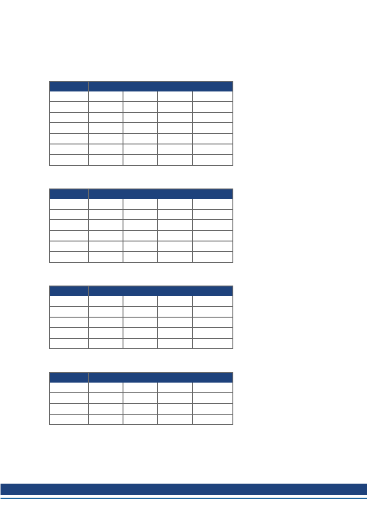
See tables below for continuous torque capability at rotational speed based on size of RGM joint and duty
cycle percentage (%).
RGM14 - Continuous Torque Capability (Nm)
负 载 周期
RPM 25% 50% 75% 100%
5 13.5 13.5 13.5 13.5
10 13.5 13.5 13.5 13.5
15 13.5 13.5 13.5 13.5
20 13.5 13.5 13.5 13.5
25 13.5 13.5 11.1 9.6
30 0.5 .035 0.29 0.25
RGM17 - Continuous Torque Capability (Nm)
负 载 周期
RPM 25% 50% 75% 100%
5 49 49 49 49
10 49 49 49 44
15 49 49 45.5 40
20 49 49 40.9 35.4
25 47 42.7 34.9 30.2
RGM20 - Continuous Torque Capability (Nm)
负 载 周期
RPM 25% 50% 75% 100%
5 61 61 61 60.7
10 61 61 61 56.4
15 61 61 60.3 52.2
20 61 57 49.4 42.8
RGM25 - Continuous Torque Capability (Nm)
负 载 周期
RPM 25% 50% 75% 100%
5 133 133 128 111
10 133 118 96.6 83.7
15 79.8 56.4 46.1 39.9
Kollmorgen | kdn.Kollmorgen.com | February 2019 12
Page 13

RGM User Manual | 7 Rotation Limits
7 Rotation Limits
RGMunits may be rotated continuously in either direction when used as a single axis. However, when
assembled into a robot with multiple axes/degrees of freedom and the "daisy chain" wiring in the center of the
output plate is used to connect joint-to-joint or joint-to-arm, the maximum rotation in either direction is +/- 360°
mechanical. If this angular limit is exceeded, connecting wires may be damaged and the warranty will be
voided.
13 Kollmorgen | kdn.Kollmorgen.com | February 2019
Page 14

RGM User Manual | 8 Accuracy & Repeatability
8 Accuracy & Repeatability
Accuracy of RGM output plate absolute encoder is 0.1° mechanical. Repeatability is 0.001° mechanical.
Kollmorgen | kdn.Kollmorgen.com | February 2019 14
Page 15

RGM User Manual | 9 Maximum Thermal Ratings
9 Maximum Thermal Ratings
The harmonic gearing used in RGM is the most thermally sensitive component in the assembly. It is
restricted to a maximum case temperature of 50°C. Users are advised that when operating RGM in
ambient temperatures higher than the standard rated temperature of 22°C, de-rated torque/speed performance
should be expected and duty cycles should be adjusted lower than shown in Duty Cycle to prevent exceeding
50°C case temperature of the gearing. Otherwise, grease may be degraded and premature failure of the
gearing may occur. If RGM is used outside the recommended thermal rating of the gearing, RGM warranty
may be voided. RGM is equipped with an internal linear thermistor on the gearing case to assist customers
with proper thermal and duty cycle management, so that maximum performance and longest life of RGM can
be achieved.
15 Kollmorgen | kdn.Kollmorgen.com | February 2019
Page 16

RGM User Manual | 10 Monitoring Thermistor
10 Monitoring Thermistor
The thermistor in RGM is connected to the drive electronics PCB printed circuit board) inside the rear cover.
When the user’s computer/controller is communicating with RGM via the serial port or CANopen
communication bus drive analog input 4 is the gear case (50°C max rating) thermistor. It is the user’s
responsibility to include provisions in the control system to monitor the thermistor at frequent intervals and
take actions such as reducing speed of motion or reducing duty cycle to keep gear case temperature within
rated limits.
Thermistor CID Sub Index Data
Gear 2206h 0 C° 16-bit
Kollmorgen | kdn.Kollmorgen.com | February 2019 16
Page 17

RGM User Manual | 11 Brake Function & Manually Releasing the Brake
11 Brake Function & Manually Releasing the Brake
Please be sure to review "Important Brake Usage Guidelines" (➜ p. 8)
11.1 About the Brake Function
RGM is equipped with a power-off park brake, meaning that the brake is mechanically engaged and prevents
rotation (within its inherent +/- 0.9° backlash characteristic) of the output plate when no power is applied. In
normal operation, when the RGM drive is enabled by the user’s controller, the energized brake coil will
release, accompanied by an audible "click". Normal motion commands may be performed after the brake
releases. In the same manner, when the RGM drive is disabled by the user’s controller, power is removed
from the coil and the brake will mechanically engage with an audible "click".
11.2 Manually Releasing the Brake
If the user needs to manually rotate the output plate of the RGM unit when no power is available to electrically
release the brake, it is possible to manually release it. Remove the 3 screws and the blue rear cover as shown
in Figure 1: Removing the Rear Cover of an RGM.
Figure 1: Removing the Rear Cover of an RGM.
Using a thin diameter tool, push downward on the brake release button to compress the spring below it (see
"Push to release the RGM's brake." (➜ p. 18)). As long as the button is held downward to keep the spring
compressed, the user may manually rotate the unit to desired position.
17 Kollmorgen | kdn.Kollmorgen.com | February 2019
Page 18

RGM User Manual | 11 Brake Function & Manually Releasing the Brake
Figure 2: Push to release the RGM's brake.
Kollmorgen | kdn.Kollmorgen.com | February 2019 18
Page 19

RGM User Manual | 12 Bolting Joint-to-Joint, Mounting Screws
12 Bolting Joint-to-Joint, Mounting Screws
When assembling multiple RGM units together in a joint-to-joint configuration or adding an arm to the output
plate of an RGM, the required screw sizes and tightening torque values are listed in the table below. Class
12.9 steel socket head cap screws are suggested, with a corrosion resistant coating such as Zinc. Stainless
steel screws are not recommended due to their reduced strength.
RGM Mounting Screws
Model Fastener Size Torque (Nm)
RGM14 M3 x 8mm long SHCS 1.81
RGM17 M3 x 6mm long SHCS 1.81
RGM20 M3 x 8mm long SHCS 1.81
RGM25 M4 x 10mm long SHCS 4.29
The application of removable thread locking adhesive to all screws is recommended.
19 Kollmorgen | kdn.Kollmorgen.com | February 2019
Page 20

RGM User Manual | 13 Environmental Requirements
13 Environmental Requirements
Normal performance ratings for RGM may be achieved in a room ambient temperature of 22°C. RGM may be
used in ambient temperatures up to 40°C with de-rated performance and duty cycle capabilities. In such
cases, it will be necessary to monitor the thermistor and adjust the motion cycle accordingly to protect the
gearing. RGM is designed for stationary mounting in a general indoor industrial environment. RGM should not
be used in applications where excessive dust, high shock and vibration (vehicles, etc.), corrosive
substances, explosive materials or operation in a vacuum are required. See IP Rating for moisture resistance
and IP rating details. Consult factory for non-standard applications.
Kollmorgen | kdn.Kollmorgen.com | February 2019 20
Page 21

RGM User Manual | 14 IP Rating
14 IP Rating
RGM is designed to meet an IP54 rating (resistant to dust and splashing water) when properly installed using
the rear cover gaskets, cover screws with o-rings, plastic joint-to-joint seal rings and joint-to-joint flexible seal
bands (see Environmental Requirements), which are available for purchase from Kollmorgen as an accesory
(RGMXX Customer Parts Kit).. The customer has responsibility for assuring proper fit of the rings and bands
when assembled into the application and for properly installing and confirming a seal at the rear cover if it has
been removed. The customer’s hardware design must include proper sealing provisions (fit, o-ring, gasket,
etc.) at the RGM mounting flange to achieve IP54 compliance.
21 Kollmorgen | kdn.Kollmorgen.com | February 2019
Page 22

RGM User Manual | 15 Joint-to-Joint Plastic Rings & Rubber Bands
15 Joint-to-Joint Plastic Rings & Rubber Bands
For applications where multiple RGM units will be assembled together in a direct joint-to-joint configuration
and sealing (IP54 or lower) is desired, Kollmorgen offers an optional seal kit for the bolted joint (RGMXX
Customer Parts Kit). This kit includes mounting screws, a plastic sealing ring (see Figure 4) and a flexible
seal band (see Figure 5).
1. Before bolting the two RGM units together, place the flexible band over the housing behind the output
plate as shown in Figure 3.
Figure 3: Position the band at the start of the process.
2. Then place the plastic ring into the housing pilot at the output plate end as shown below in Figure 4.
Figure 4: Placing the plastic ring into the housing pilot.
3. Confirm that the plastic ring is pushed inward until it is flush with the housing as shown in Figure 5 ,
so it does not obstruct access to the threaded holes on the OD of the mounting plate.
Kollmorgen | kdn.Kollmorgen.com | February 2019 22
Page 23

RGM User Manual | 15 Joint-to-Joint Plastic Rings & Rubber Bands
Figure 5: Push the flexible seal band until flush with the housing plate.
4. After the two RGM units are bolted together and the screws are properly torqued (Figure 6 left), slide
the plastic ring outward so it covers the screws and touches the stationary flange of the second RGM
unit (Figure 6 right).
Figure 6: Units are bolted together (left), and the plastic ring is set to cover the screws (right).
5. Then move the flexible seal band so it holds the plastic ring in position (Figure 7).
Figure 7: Move the flexible seal band so it holds the plastic ring in place.
23 Kollmorgen | kdn.Kollmorgen.com | February 2019
Page 24

RGM User Manual | 16 Rear Cover Removal & Daisy Chain Connections
16 Rear Cover Removal & Daisy Chain Connections
RGM units are provided with 4 wires that pass through the center of the gear output plate to make it easy for
the user to “daisy chain” power and communication from one robot joint to the next. Red (+) and Black (-)
provide 48VDC supply to the next joint. The twisted pair with White (High) and Blue (Low) provide CANopen
communication to the next joint. When bolting two RGM assemblies together in a joint-to-joint configuration
(see section 10), great care must be taken to avoid damaging these wires.
1. Remove the 3 screws and blue rear cover as shown in Figure 8.
Figure 8: Remove the blue cover
2. Route the incoming wires through the upper access hole in the housing as shown in Figure 9. Care
must be taken to route them cleanly around the motor power wires that attach to the drive PCB in this
same area.
Figure 9: Routing wires between joints
3. As the two joints are gradually drawn together to reach their final bolting position, avoid slack and keep
constant tension on the wires to avoid pinching or mashing them. See Figure 10.
Kollmorgen | kdn.Kollmorgen.com | February 2019 24
Page 25

RGM User Manual | 16 Rear Cover Removal & Daisy Chain Connections
Figure 10: Keep wires tight to avoid pinching
4. Insert the red and black power wires with ferrules into the vertical poke-in connector shown in Figure
11. Note polarity on the PCB silkscreen, insert red into the “+” position and black into the “-“position.
For best results, be sure the smooth side of the crimped ferrule is facing the white spring side of the
connector slot when pushing it in. See Board Layout (➜ p. 34) for a diagram of the PCB.
Figure 11: Power and CANopen connections
5. After insertion, give the wires a light tug to confirm they are properly inserted.
If the wire needs to be removed from the poke-in connector, push downward on the white spring portion of the connector with a small screwdriver and lightly pull upward on the wire until it releases.
25 Kollmorgen | kdn.Kollmorgen.com | February 2019
Page 26

RGM User Manual | 16 Rear Cover Removal & Daisy Chain Connections
6. Plug the CANopen (blue and white twisted pair) into connector P1 on the drive PCB as shown in Fig-
ure 11. Be sure the connectors fully seat on the post pins. PCB silkscreen note positions for W (white
- CAN high) and B (blue - CAN low).
To remove, pull straight up on the body of the black plastic connector housing.. Be sure wires are arranged to
avoid accidentally pinching them when the cover is re-installed.
Kollmorgen | kdn.Kollmorgen.com | February 2019 26
Page 27

RGM User Manual | 17 Daisy Chain Wire Sizes, Colors, and Functions
17 Daisy Chain Wire Sizes, Colors, and Functions
Color Function Size
RGM14 RGM17 RGM20 RGM25
Red 48 VDC Positive 20 AWG 18 AWG
Black 48 VDC Negative 20 AWG 18 AWG
White CANopen High 24AWG
Blue CANopen Low 24AWG
CANopen connector housing – TE part number 7-87499-2
CANopen connector contact – TE part number 102128-1 contacts and TE crimp tool 91517-1
27 Kollmorgen | kdn.Kollmorgen.com | February 2019
Page 28

RGM User Manual | 18 RGM Workbench Software & Drive Commissioning
18 RGM Workbench Software & Drive Commissioning
Please refer to separate document "RGM Workbench User Manual" for software and interface instructions.
Kollmorgen | kdn.Kollmorgen.com | February 2019 28
Page 29

RGM User Manual | 19 Serial Cable Part Number
19 Serial Cable Part Number
A serial communication cable (part #969745) is available for purchase from Kollmorgen.
29 Kollmorgen | kdn.Kollmorgen.com | February 2019
Page 30

RGM User Manual | 20 CANopen Termination
20 CANopen Termination
RGM drive CAN addresses are assigned electronically via the serial port (connector P3) during the
commissioning process. See separate documents for further instructions.
l RGM Workbench User Manual
l RGM CANopen Manual
Note that the CANopen network requires 1 termination resistor at the source (master) and 1 termination
resistor at the final drive at the end of the network. RGM drive PCB is equipped with a jumper resistor at
connector location P2. Placing the jumper across both posts of connector P2 puts the termination resistor into
the circuit. Removing the jumper or moving it to a position that only contacts one of the P2 posts will remove
the termination resistor from the circuit.
Kollmorgen | kdn.Kollmorgen.com | February 2019 30
Page 31

RGM User Manual | 21 Brake Initialization
21 Brake Initialization
When the RGM joint is enabled it is possible that, depending on the robot position, gravitational forces from
the robot’s weight can prevent the brake from disengaging. The recommended initialization sequence is to:
1. Enable the drive.
2. Then move the axis back and forth to insure the brake solenoid is fully retracted
The RGM uses a pin in spoke brake, a 4 spoke wheel is on mounted on the motor, this means there is a brake
position every 90 degrees of the motor position or .89 degrees of the gear output. The pin which contacts the
spokes during braking is activated with a solenoid. Power must be applied to the solenoid to release the
brake. Once the solenoid is energized to release the brake, the controller needs to move (shake) the joint back
and forth to ensure the brake pin is not hung on the brake wheel. The recommended move distance is +/- 0.5
degrees of gear motion.
Typical Motion Parameters
T move Degree Deg/sec Deg/sec
0.05 1 40 1600
0.1 1 20 400
0.2 1 10 100
2
21.1 RGM Enable/ Brake Initialization Procedure
1. Controller Enables Drive, this turns on Power bridge and applies 48 Vdc to brake for .5 seconds
2. Controller commands +/-.5-degree relative motions with motion time of .06 seconds
1. +.5 degrees
2. -.5 degrees
3. +.5 degrees
4. -.5 degree
3. Perform a longer move to insure brake is not stuck on the pin.
Times shown are typical
31 Kollmorgen | kdn.Kollmorgen.com | February 2019
Page 32

RGM User Manual | 22 Regeneration Warning
22 Regeneration Warning
A rotating motor has kinetic energy, regeneration occurs when the kinetic energy that was stored in the motor
during motion is returned to the system during deceleration. This energy must be absorbed by the DC bus
Capacitators, which in turn raises the bus voltage or dissipated by friction.
It is possible under certain conditions that regenerative action will raise the bus voltage above the RGM
drives rated maximum voltage. If this occurs the drives will shut down with an over voltage fault. If
regeneration does shut down the drive, the user will either need to modify the application by slowing down the
process, or use a power supply with regeneration capability.
Kollmorgen | kdn.Kollmorgen.com | February 2019 32
Page 33

RGM User Manual | 23 End Effectors
23 End Effectors
Kollmorgen does not currently offer tool mount or end effector accessories for RGM. If customers intend to
design their own mechanical interface for mounting an end effector, mechanical dimensions of the RGM
output plate can be found on the Kollmorgen website. If the end effector will rely upon the RGM daisy chain
wiring for DC power, then motion of the output plate must be restricted to +/- 360°. If end effector power will
be provided by another wiring path, and the RGM daisy chain will not be used for this purpose or connected to
the end effector, then continuous rotation of the RGM output plate is possible. Customer is responsible for
communication and I/O to the end effector external to the RGM wiring circuit.
33 Kollmorgen | kdn.Kollmorgen.com | February 2019
Page 34

24 Board Layout
24.1 CANopen
RGM User Manual | 24 Board Layout
Kollmorgen | kdn.Kollmorgen.com | February 2019 34
Page 35

RGM User Manual | 24 Board Layout
24.2 EtherCAT
35 Kollmorgen | kdn.Kollmorgen.com | February 2019
Page 36

RGM User Manual | 25 Data Sheets
25 Data Sheets
25.1 RGM14 37
25.2 RGM17 38
25.3 RGM20 39
25.4 RGM25 40
Kollmorgen | kdn.Kollmorgen.com | February 2019 36
Page 37

RGM User Manual | 25 Data Sheets
25.1 RGM14
RGM14 Specifications
Specifications RGM14A-ANCN-XXX
Supply Voltage 48 (+/- 10%) VDC
Maximum Supply Currents 10 Amps RMS
Continuous Supply Current 3.8 Amps RMS
Maximum Intermittent Torque 34 Nm
Maximum Intermittent Speed 35 RPM, 210°/sec
Continuous Torque (22°C Ambient, 50% Duty Cycle) 13.5 Nm (see graph/table)
Speed at Continuous Torque (22°C, 50% Duty Cycle) 20 RPM
Torque Constant (Kt) 0.110 Nm/Amp RMS
Maximum Angular Movement (with center shaft wiring connected)
Maximum Angular Movement (without center shaft wiring connected)
Maximum Gear Case Temperature 50° C
Absolute Encoder Resolution 19 bits, 0.0007° Mechanical
Accuracy 0.1° Mechanical
Repeatability 0.001° Mechanical
Communication Fieldbus CANopen DS301 and DS402
Center Shaft Wiring (4 wires)
Red
Black
White
Blue
Weight 1.48 kg
IP Rating (when properly installed per instructions)* IP54
Mounting Fasteners M3 x 8mm long class 12.9 socket head cap
* Requires optional Kollmorgen ring, band and gasket kit plus customer interface surface to complete seal
+/- 360° Mechanical
infinite° Mechanical
20 AWG / + 48VDC
20 AWG / -48VDC
24 AWG / CANopen high
24 AWG / CANopen low
screw
RGM14 - 连 续 转矩 能 力 (Nm)
Duty Cycle
RPM 25% 50% 75% 100%
5 13.5 13.5 13.5 13.5
10 13.5 13.5 13.5 13.5
15 13.5 13.5 13.5 13.5
20 13.5 13.5 13.5 13.5
25 13.5 13.5 11.1 9.6
30 0.5 0.35 0.29 0.25
* at 22°C ambient. Performance will be reduced at higher ambient
temperatures
37 Kollmorgen | kdn.Kollmorgen.com | February 2019
Page 38

RGM User Manual | 25 Data Sheets
25.2 RGM17
RGM17 Specifications
Specifications RGM14A-ANCN-XXX
Supply Voltage 48 (+/- 10%) VDC
Maximum Supply Currents 10 Amps RMS
Continuous Supply Current 4.88 Amps RMS
Maximum Intermittent Torque 66 Nm
Maximum Intermittent Speed 30 RPM, 180°/sec
Continuous Torque (22°C Ambient, 50% Duty Cycle) 49 Nm (see graph/table)
Speed at Continuous Torque (22°C, 50% Duty Cycle) 20 RPM
Torque Constant (Kt) 0.129 Nm/Amp RMS
Maximum Angular Movement (with center shaft wiring connected)
Maximum Angular Movement (without center shaft wiring
connected)
Maximum Gear Case Temperature 50° C
Absolute Encoder Resolution 19 bits, 0.0007° Mechanical
Accuracy 0.1° Mechanical
Repeatability 0.001° Mechanical
Communication Fieldbus CANopen DS301 and DS402
Center Shaft Wiring (4 wires)
Red
Black
White
Blue
Weight
IP Rating (when properly installed per instructions)* IP54
Mounting Fasteners M4 x 10mm long class 12.9 socket head cap
* Requires optional Kollmorgen ring, band and gasket kit plus customer interface surface to complete seal
+/- 360° Mechanical
infinite° Mechanical
20 AWG / + 48VDC
20 AWG / -48VDC
24 AWG / CANopen high
24 AWG / CANopen low
1.97 kg
screw
RGM17 - 连 续 转矩 能 力 (Nm)
Duty Cycle
RPM 25% 50% 75% 100%
5 49 49 49 49
10 49 49 49 44
15 49 49 45.5 40
20 49 49 40.9 35.4
25 47 42.7 34.9 30.2
* at 22°C ambient. Performance will be reduced at higher ambient
temperatures
Kollmorgen | kdn.Kollmorgen.com | February 2019 38
Page 39

RGM User Manual | 25 Data Sheets
25.3 RGM20
RGM20 Specifications
Specifications RGM20A-ANCN-XXX
Supply Voltage 48 (+/- 10%) VDC
Maximum Supply Currents 20 Amps RMS
Continuous Supply Current 7.5 Amps RMS
Maximum Intermittent Torque 102 Nm
Maximum Intermittent Speed 25 RPM, 150°/sec
Continuous Torque (22°C Ambient, 50% Duty Cycle) 61 Nm (see graph/table)
Speed at Continuous Torque (22°C, 50% Duty Cycle) 15 RPM
Torque Constant (Kt) 0.123 Nm/Amp RMS
Maximum Angular Movement (with center shaft wiring connected)
Maximum Angular Movement (without center shaft wiring connected)
Maximum Gear Case Temperature 50 °C
Absolute Encoder Resolution 19 bits, 0.0007° Mechanical
Accuracy 0.1° Mechanical
Repeatability 0.001° Mechanical
Communication Fieldbus CANopen DS301 and DS402
Center Shaft Wiring (4 wires)
Red
Black
White
Blue
Weight 2.56 kg
IP Rating (when properly installed per instructions)* IP54
Mounting Fasteners M3 x 8mm long class 12.9 socket head cap
* Requires optional Kollmorgen ring, band and gasket kit plus customer interface surface to complete seal
+/- 360° Mechanical
infinite° Mechanical
18 AWG / + 48VDC
18 AWG / -48VDC
24 AWG / CANopen high
24 AWG / CANopen low
screw
RGM20 - 连 续 转矩 能 力 (Nm)
Duty Cycle
RPM 25% 50% 75% 100%
5 61 61 61 60.7
10 61 61 61 56.4
15 61 61 60.3 52.2
20 61 57 49.4 42.8
* at 22°C ambient. Performance will be reduced at higher ambient
temperatures
39 Kollmorgen | kdn.Kollmorgen.com | February 2019
Page 40

RGM User Manual | 25 Data Sheets
25.4 RGM25
RGM25 Specifications
Specifications RGM14A-ANCN-XXX
Supply Voltage 48 (+/- 10%) VDC
Maximum Supply Currents 20 Amps RMS
Continuous Supply Current 10 Amps RMS
Maximum Intermittent Torque 194 Nm
Maximum Intermittent Speed 20 RPM, 120°/sec
Continuous Torque (22°C Ambient, 50% Duty Cycle) 118 Nm (see graph/table)
Speed at Continuous Torque (22°C, 50% Duty Cycle) 10 RPM
Torque Constant (Kt) 0.141 Nm/Amp RMS
Maximum Angular Movement (with center shaft wiring connected)
Maximum Angular Movement (without center shaft wiring
connected)
Maximum Gear Case Temperature 50° C
Absolute Encoder Resolution 19 bits, 0.0007° Mechanical
Accuracy 0.1° Mechanical
Repeatability 0.001° Mechanical
Communication Fieldbus CANopen DS301 and DS402
Center Shaft Wiring (4 wires)
Red
Black
White
Blue
Weight 4.20 kg
IP Rating (when properly installed per instructions)* IP54
Mounting Fasteners M4 x 10mm long class 12.9 socket head cap
* Requires optional Kollmorgen ring, band and gasket kit plus customer interface surface to complete seal
+/- 360° Mechanical
infinite° Mechanical
18 AWG / + 48VDC
18 AWG / -48VDC
24 AWG / CANopen high
24 AWG / CANopen low
screw
RGM25 - 连 续 转矩 能 力 (Nm)
Duty Cycle
RPM 25% 50% 75% 100%
5 133 133 128 111
10 133 118 96.6 83.7
15 79.8 56.4 46.1 39.9
* at 22°C ambient. Performance will be reduced at higher ambient
temperatures
Kollmorgen | kdn.Kollmorgen.com | February 2019 40
Page 41

RGM User Manual | 26 Index
26 Index
A
Absolute encoder 14
Acceleration 11
Accuracy 14
B
Backlash 17
Brake, park 17
C
CANopen 24, 26-27
E
End Effector 33
H
Harmonic gearing 15
I
IP54 21-22
J
Joint seal kit 22
O
Output plate 19, 24, 33
P
Performance rating 20
R
Rotation 13
S
Screws, mounting 19
Serial cable, about 29
Speed 15
Speed, max RPM 10
Speed, RPM 12
T
Temperature, max. 15
Thermal rating 15
Thermal sensitivity 15
Thermistors 16, 20
41 Kollmorgen | kdn.Kollmorgen.com | February 2019
Page 42

RGM User Manual | 26 Index
Torque 11-12, 15
Torque, tightening 19
V
Voltage 9
W
Wiring 27
Wiring, daisy chain 13, 24
Workbench 28
Kollmorgen | kdn.Kollmorgen.com | February 2019 42
Page 43

About Kollmorgen
Kollmorgen is a leading provider of motion systems and components for machine builders. Through world-class
knowledge in motion, industry-leading quality and deep expertise in linking and integrating standard and custom
products, Kollmorgen delivers breakthrough solutions that are unmatched in performance, reliability and easeof-use, giving machine builders an irrefutable marketplace advantage.
Join the Kollmorgen Developer Network for product support. Ask the community ques-
tions, search the knowledge base for answers, get downloads, and suggest improvements.
North America
Kollmorgen
203A West Rock Road
Radford, VA 24141
USA
Web:
Mail:
www.Kollmorgen.com
support@Kollmorgen.com
Tel.: +1 - 540 - 633 - 3545
Fax: +1 - 540 - 639 - 4162
South America
Kollmorgen
Avenida Tamboré, 1077 Tamboré Barueri - SP Brasil
CEP:06460-000
Web: www.Kollmorgen.com
Tel.: +55 11 4191-4771
Europe
Kollmorgen Europe GmbH
Pempelfurtstraße 1
40880 Ratingen
Germany
Web: www.Kollmorgen.com
Mail: technik@Kollmorgen.com
Tel.: +49 - 2102 - 9394 - 0
Fax: +49 - 2102 - 9394 - 3155
China and Southeast Asia
Kollmorgen Asia
Room 302, Building 5,
Lihpao Plaza, 88 Shenbin Road,
Minhang District, Shanghai, China
Web: www.Kollmorgen.cn
Mail: sales.china@kollmorgen.com
Tel.: +86 - 400 - 668-2802
Fax: +81 - 216 - 248-5367
 Loading...