

Page 1
www.DanaherMotion.com
KOLLMORGEN
SERVOSTAR® MC
M-SS-005-03
Revision E
Firmware Version 5.0.0
Page 2
Record of Manual Revisions
Revision Date Description of Revision
0 3/1/1999 Preliminary issue for review
1 5/14/1999 Initial release
2 6/5/2000 New PCI and stand-alone models, new firmware features
3 8/31/2001 New firmware features
D 5/11/2005 Update examples
E 6/20/2005 Updated firmware version and dates
©1999 – 2005 Danaher Motion. All rights reserved. Printed in the USA.
DANAHER MOTION® is a registered trademark of Danaher Corporation. Danaher
Motion makes every attempt to ensure accuracy and reliability of the specifications in
this publication. Specifications are subject to change without notice. Danaher Motion
provides this information "AS IS" and disclaims all warranties, express or implied,
including, but not limited to, implied warranties of merchantability and fitness for a
particular purpose. It is the responsibility of the product user to determine the
suitability of this product for a specific application.
SERVOSTAR, GOLDLINE Motors, MOTIONLINK, Motioneering, BASIC Moves Development
Studio, Kollmorgen API and MC-BASIC are trademarks of the Kollmorgen Corporation.
VxWorks is a trademark of Wind River.
Visual Basic, Visual C++, Windows, Windows 95, Windows NT are trademarks of Microsoft
Corporation.
Safety-alert symbols used in this document are:
WARNING
CAUTION
NOTE
Warnings alert users to potential physical danger or harm. Failure
to follow warning notices could result in personal injury or death.
Cautions direct attention to general precautions, which if not
followed, could result in personal injury and/or equipment damage.
Notes highlight information critical to your understanding or use of
the product.
Page 3

Danaher Motion 06/2005 Table of Contents
Table of Contents
1. OVERVIEW ................................................................................................................................ 1
1. 1 SYSTEM HARDWARE ......................................................................................................... 2
1. 2 OPERATING SYSTEM......................................................................................................... 2
1. 3 MC-BASIC LANGUAGE COMPILER................................................................................. 2
1. 4 I/O......................................................................................................................................... 3
1. 5 SERCOS ............................................................................................................................... 3
1. 6 API........................................................................................................................................ 4
1. 7 MULTI-TASKING ................................................................................................................ 4
1. 8 USER COMMUNICATION.................................................................................................. 4
1.8.1. SERIAL COMMUNICATION .................................................................................. 5
1.8.2. TCP/IP COMMUNICATION.................................................................................. 6
1.8.3. SEND /RECEIVE DATA ........................................................................................ 8
2. BASIC MOVES DEVELOPMENT STUDIO........................................................................ 11
2. 1 COMMUNICATION .......................................................................................................... 11
2. 2 MC-BASIC.......................................................................................................................... 11
2.2.1. INSTRUCTIONS.................................................................................................. 12
2.2.2. TYPE ................................................................................................................. 12
2.2.3. CONSTANTS AND VARIABLES .......................................................................... 14
2.2.4. DATA TYPES..................................................................................................... 16
2.2.5. SYSTEM ELEMENTS .......................................................................................... 19
2.2.6. UNITS................................................................................................................ 20
2.2.7. EXPRESSIONS.................................................................................................... 20
2.2.8. AUTOMATIC CONVERSION OF DATA TYPES .................................................... 20
2.2.9. MATH FUNCTIONS............................................................................................ 23
2.2.10. STRING FUNCTIONS.......................................................................................... 24
2.2.11. SYSTEM COMMANDS........................................................................................ 25
2.2.12. PRINTING .......................................................................................................... 28
2.2.13. FLOW CONTROL ............................................................................................... 30
2. 3 PROGRAM DECLARATIONS ........................................................................................... 36
2.3.1. PROGRAM ......................................................................................................... 36
2.3.2. SUBROUTINE..................................................................................................... 36
2.3.3. USER-DEFINED FUNCTIONS ............................................................................. 37
2. 4 LIBRARIES......................................................................................................................... 38
2.4.1. GLOBAL LIBRARIES.......................................................................................... 40
M-SS-005-03 Rev E i
Page 4

Table of Contents 06/2005 Danaher Motion
2. 5 C-FUNCTIONS...................................................................................................................40
2.5.1. OBJECT FILES ....................................................................................................40
2.5.2. PROTOTYPE FILE ...............................................................................................41
2.5.3. SPECIAL CONSIDERATIONS ...............................................................................44
2. 6 SEMAPHORES ...................................................................................................................45
2.6.1. MUTUAL EXCLUSION SEMAPHORES .................................................................45
2.6.2. SYNCHRONIZATION SEMAPHORES ....................................................................46
2. 7 VIRTUAL ENTRY STATION...............................................................................................46
2. 8 OUTPUT REDIRECTION ..................................................................................................47
2. 9 FILE OPERATIONS ...........................................................................................................47
2.9.1. OPEN ...............................................................................................................47
2.9.2. OPEN #, INPUT #, CLOSE, LOC ................................................................48
2.9.3. TELL................................................................................................................48
2.9.4. SEEK................................................................................................................48
3. PROJECT...................................................................................................................................49
3. 1 PROJECT STRUCTURE ....................................................................................................49
3. 2 TASKS .................................................................................................................................49
3.2.1. GENERAL PURPOSE TASKS ...............................................................................49
3.2.2. CONFIGURATION TASK .....................................................................................51
3.2.3. AUTOEXEC TASK ..............................................................................................51
3. 3 PROGRAM DECLARATIONS............................................................................................52
3.3.1. ARRAYS.............................................................................................................53
3. 4 MULTI-TASKING...............................................................................................................55
3.4.1. LOADING THE PROGRAM...................................................................................57
3.4.2. PREEMPTIVE MULTI-TASKING & PRIORITY LEVELS ........................................57
3.4.3. INTER-TASK COMMUNICATIONS AND CONTROL..............................................57
3.4.4. MONITORING TASKS FROM THE TERMINAL .....................................................59
3.4.5. RELINQUISHING RESOURCES ............................................................................59
3. 5 EVENT HANDLER .............................................................................................................60
3.5.1. ONEVENT ..........................................................................................................60
3.5.2. EVENTON ..........................................................................................................61
3.5.3. EVENTOFF.........................................................................................................61
3.5.4. EVENTLIST ........................................................................................................61
3.5.5. EVENTDELETE...................................................................................................61
3.5.6. EVENTS AT START-UP .......................................................................................61
3.5.7. PROGRAM FLOW AND ONEVENT .....................................................................61
3. 6 SETTING UP AXES............................................................................................................ 6 2
3.6.1. AXIS DEFINITION...............................................................................................62
3.6.2. AXIS NAME .......................................................................................................62
3.6.3. DRIVE ADDRESS................................................................................................63
ii Rev E M-SS-005-03
Page 5

Danaher Motion 06/2005 Table of Contents
3.6.4. STARTING POSITION ......................................................................................... 63
3.6.5. BASIC MOVES AUTO SETUP PROGRAM.......................................................... 63
3.6.6. USER UNITS...................................................................................................... 64
3.6.7. POSITION UNITS ............................................................................................... 64
3.6.8. VELOCITY UNITS.............................................................................................. 65
3.6.9. ACCELERATION UNITS ..................................................................................... 65
3.6.10. JERK UNITS....................................................................................................... 66
3. 7 ACCELERATION PROFILE ............................................................................................. 66
3. 8 POSITION AND VELOCITY ............................................................................................. 67
3. 9 LIMITS ............................................................................................................................... 69
3.9.1. POSITION LIMITS .............................................................................................. 70
3.9.2. AXIS VELOCITY LIMITS.................................................................................... 73
3. 10 VELOCITY, ACCELERATION AND JERK RATE PARAMETERS.................................. 73
3. 11 VERIFY SETTINGS............................................................................................................ 74
3.11.1. ENABLING......................................................................................................... 74
3.11.2. MOTION FLAGS ................................................................................................ 74
3.11.3. MOVE................................................................................................................ 74
3. 12 SERCOS ............................................................................................................................. 75
3.12.1. COMMUNICATION PHASES ............................................................................... 76
3.12.2. TELEGRAMS...................................................................................................... 76
3.12.3. TELEGRAM TYPES ............................................................................................ 77
3.12.4. CYCLIC VS. NON-CYCLIC COMMUNICATION................................................... 78
3.12.5. IDNS................................................................................................................. 78
3.12.6. POSITION AND VELOCITY COMMANDS............................................................ 79
3.12.7. SERCOS SUPPORT........................................................................................... 79
3. 13 LOOPS ............................................................................................................................... 81
3.13.1. STANDARD POSITION LOOP.............................................................................. 82
3.13.2. DUAL-FEEDBACK POSITION LOOP ................................................................... 82
3.13.3. VELOCITY LOOP............................................................................................... 83
3. 14 SIMULATED AXES............................................................................................................ 83
4. SINGLE-AXIS MOTION......................................................................................................... 85
4. 1 MOTION GENERATOR .................................................................................................... 85
4.1.1. MOTION CONDITIONS....................................................................................... 85
4.1.2. MOTION BUFFERING......................................................................................... 87
4.1.3. OVERRIDE VERSUS PERMANENT ...................................................................... 87
4.1.4. ACCELERATION PROFILE.................................................................................. 88
4.1.5. JOG.................................................................................................................... 88
4.1.6. STOP ................................................................................................................. 89
4.1.7. PROCEED........................................................................................................... 89
M-SS-005-03 Rev E iii
Page 6

Table of Contents 06/2005 Danaher Motion
4.1.8. MOVE ................................................................................................................90
4.1.9. VELOCITY OVERRIDE........................................................................................98
4. 2 MOTION EXAMPLES ........................................................................................................98
4.2.1. POSITION CAPTURE ...........................................................................................98
4.2.2. HOMING.............................................................................................................99
4.2.3. REGISTRATION ................................................................................................101
4.2.4. GATING............................................................................................................102
4.2.5. CLAMPING.......................................................................................................102
4.2.6. PIPEMODE ....................................................................................................103
5. MASTER-SLAVE....................................................................................................................105
5. 1 MASTER SOURCES .........................................................................................................105
5. 2 GEARING..........................................................................................................................106
5.2.1. ENABLE GEARING ...........................................................................................106
5.2.2. DISABLE GEARING ..........................................................................................106
5.2.3. INCREMENTAL MOVES....................................................................................107
5. 3 CAMMING........................................................................................................................108
5.3.1. KEY FEATURES................................................................................................108
5.3.2. GEARRATIO................................................................................................109
5.3.3. INCREMENTAL MOVES....................................................................................109
5.3.4. CAM TABLES...................................................................................................109
5.3.5. CAM CYCLES...................................................................................................111
5.3.6. CREATE CAM TABLES.....................................................................................113
5.3.7. OPERATING CAMS...........................................................................................115
5. 4 SIMULATED AND MASTER-SLAVE AXES ....................................................................119
5.4.1. FIXED-SPEED MASTERS ..................................................................................119
5.4.2. MONITOR PHYSICAL AXES .............................................................................119
5.4.3. SYNCHRONIZE SLAVE AXES ...........................................................................119
6. GROUPS...................................................................................................................................121
6. 1 SET UP..............................................................................................................................121
6. 2 DELETEGROUP ..............................................................................................................121
6. 3 ACCELERATION PROFILES ..........................................................................................121
6.3.1. ACCELERATION AND DECELERATION.............................................................121
6. 4 POSITION.........................................................................................................................122
6.4.1. VECTOR...........................................................................................................122
6.4.2. SCALAR ...........................................................................................................122
6. 5 VELOCITY ........................................................................................................................123
6. 6 LIMITS ..............................................................................................................................123
6.6.1. GENERATOR ....................................................................................................123
6.6.2. REALTIME........................................................................................................123
iv Rev E M-SS-005-03
Page 7

Danaher Motion 06/2005 Table of Contents
6.6.3. POSITION......................................................................................................... 123
6.6.4. VELOCITY....................................................................................................... 124
6. 7 ACCELERATION............................................................................................................. 124
6. 8 VELOCITY, ACCELERATION, DECELERATION AND JERK RATES......................... 124
6. 9 MOTION........................................................................................................................... 125
6.9.1. ATTACH TASK AND AXIS ............................................................................... 125
6.9.2. ENABLE........................................................................................................ 125
6.9.3. MOTION FLAGS .............................................................................................. 126
6.9.4. STOP ............................................................................................................. 126
6.9.5. PROCEED.................................................................................................... 127
6.9.6. MOVE ........................................................................................................... 127
6.9.7. CIRCLE........................................................................................................ 128
6.9.8. CHAIN COMMANDS ........................................................................................ 129
6.9.9. BLENDING....................................................................................................... 129
6. 10 MOVE CONTROL............................................................................................................ 131
6.10.1. SETTLING TIME .............................................................................................. 132
6.10.2. START MOVES ................................................................................................ 132
6.10.3. CHAIN MOVES................................................................................................ 133
6.10.4. MULTI-STEP MOVES ...................................................................................... 133
6.10.5. SYNCHRONIZE MULTIPLE AXES..................................................................... 134
6.10.6. CLEAR A PENDING MOVE.............................................................................. 135
6. 11 VELOCITY OVERRIDE................................................................................................... 135
7. COMPENSATION TABLES................................................................................................. 137
7.1.1. SPECIFICATION ............................................................................................... 137
7.1.2. ACCESS DATA ................................................................................................ 138
7.1.3. DEFINE............................................................................................................ 138
7.1.4. LOAD/SAVE FROM A FILE .............................................................................. 139
7.1.5. SET AND QUERY VALUES............................................................................... 139
7.1.6. ACTIVATE....................................................................................................... 139
7.1.7. QUERY ACTUAL POSITIONS ........................................................................... 139
7.1.8. MULTI-DIMENSIONAL CORRECTION.............................................................. 139
8. PHASER................................................................................................................................... 141
8.1.1. PROFILER........................................................................................................ 141
8.1.2. EXECUTE ........................................................................................................ 142
8.1.3. CANCEL .......................................................................................................... 142
8.1.4. SERIAL PHASER........................................................................................... 142
9. GENERIC ELEMENTS......................................................................................................... 143
9. 1 ELEMENTID.................................................................................................................... 143
9.1.1. DECLARATION................................................................................................ 144
9.1.2. ASSIGNMENT .................................................................................................. 144
M-SS-005-03 Rev E v
Page 8

Table of Contents 06/2005 Danaher Motion
9.1.3. LIMITATIONS ...................................................................................................145
9.1.4. FUNCTIONS......................................................................................................146
9. 2 WITH.................................................................................................................................148
10. INPUT/OUTPUT .....................................................................................................................149
10. 1 STANDARD I/O ................................................................................................................149
10. 2 SOFTWARE I/O................................................................................................................149
10.2.1. BIT-ORIENTED SOFTWARE I/O........................................................................149
10.2.2. LONG-WORD-ORIENTED SOFTWARE I/O........................................................150
10. 3 PLS (PROGRAMMABLE LIMIT SWITCH) .....................................................................150
10.3.1. ENABLE AND DISABLE ....................................................................................150
10.3.2. SWITCH POSITIONS..........................................................................................151
10.3.3. REPETITION INTERVAL....................................................................................152
10.3.4. POLARITY........................................................................................................152
10.3.5. HYSTERESIS.....................................................................................................152
10.3.6. ENABLE AND DISABLE ....................................................................................152
10.3.7. PLS OUTPUT STATE........................................................................................153
10.3.8. SET UP.............................................................................................................153
10. 4 EXTERNAL ENCODERS..................................................................................................154
10. 5 PC104................................................................................................................................155
10.5.1. CONFIGURING PC104 CARDS .........................................................................155
10.5.2. INSTALLATION.................................................................................................155
10.5.3. COMMANDS.....................................................................................................156
11. ERROR HANDLING..............................................................................................................157
11. 1 CONTEXT.........................................................................................................................157
11.1.1. TASK CONTEXT...............................................................................................157
11.1.2. SYSTEM CONTEXT...........................................................................................159
11.1.3. TERMINAL CONTEXT.......................................................................................160
11. 2 WATCHDOG ....................................................................................................................160
11.2.1. WATCHDOG SETUP.........................................................................................161
11.2.2. CYCLE THE WATCHDOG.................................................................................161
11.2.3. RESET THE WATCHDOG..................................................................................161
11. 3 UEA (USER ERROR ASSERTION)..................................................................................162
11. 4 EXCEPTIONS...................................................................................................................162
11.4.1. DECLARATION.................................................................................................162
11.4.2. DELETION........................................................................................................163
11.4.3. ASSERTION ......................................................................................................163
11.4.4. LOG .................................................................................................................164
11.4.5. QUERY.............................................................................................................164
11.4.6. PRINT...............................................................................................................164
11.4.7. LIMITATIONS ...................................................................................................164
vi Rev E M-SS-005-03
Page 9

Danaher Motion 06/2005 Table of Contents
APPENDIX A ................................................................................................................................... 165
SAMPLE NESTING PROGRAM............................................................................................... 165
SUBROUTINE EXAMPLE........................................................................................................ 166
SAMPLE AUTOSETUP PROGRAM ........................................................................................ 167
APPENDIX B.................................................................................................................................... 171
NON-HOMOGENOUS GROUPS............................................................................................. 171
KINEMATICS ..................................................................................................................... 171
COUPLING............................................................................................................................... 173
JOINTS............................................................................................................................... 174
ROBOT MODELS ............................................................................................................... 175
INTERPOLATION................................................................................................................ 176
CARTESIAN PROFILE......................................................................................................... 179
WORKING ENVELOPE ....................................................................................................... 180
ROBOT CONFIGURATIONS ................................................................................................ 181
POINTS ..................................................................................................................................... 181
DECLARATION ..................................................................................................................182
VARIABLES ....................................................................................................................... 182
CONSTANT POINTS ........................................................................................................... 182
VECTORS........................................................................................................................... 183
PROPERTIES ...................................................................................................................... 183
POINT DIMENSION............................................................................................................ 183
POINT ASSIGNMENT ......................................................................................................... 184
SINGLE COORDINATE POINT ASSIGNMENT...................................................................... 184
POINT QUERY ................................................................................................................... 184
SINGLE COORDINATE POINT QUERY................................................................................ 184
OPERATORS ...................................................................................................................... 184
POINTS IN FUNCTIONS ...................................................................................................... 186
MOTION COMMANDS........................................................................................................ 187
ANALOG BEHAVIOR ......................................................................................................... 187
POINT AS AN EXPRESSION ............................................................................................... 187
GROUP POINT PROPERTIES............................................................................................... 188
IN FUNCTIONS................................................................................................................... 188
QUERY .............................................................................................................................. 189
OPERATORS ...................................................................................................................... 189
PASS STRUCTURE ............................................................................................................. 189
LIMITATIONS .................................................................................................................... 190
CONVEYER TRACKING .......................................................................................................... 190
WINDOW DECLARATION .................................................................................................. 191
TRACKING......................................................................................................................... 191
M-SS-005-03 Rev E vii
Page 10

Table of Contents 06/2005 Danaher Motion
MOVING FRAME ................................................................................................................191
TRACKING PROCESS..........................................................................................................192
CUSTOMER SUPPORT ............................................................................................................194
viii Rev E M-SS-005-03
Page 11

Danaher Motion 06/2005 Overview
1. OVERVIEW
This manual describes how to use the SERVOSTAR MC (Multi-axis
Controller) product. To execute the examples described in this manual, you
must at least have a SERVOSTAR MC and BASIC Moves Development
installed on your host computer. Some examples further require that
Studio
you have a drive installed and connected to the MC using the SERCOS
Interface
procedures for all the necessary installations.
Version 5.0.0 of the firmware incorporates many new commands, functions,
and properties, and, in some instances, the behavior of functions,
commands, and properties found in previous versions of the firmware have
been changed. This edition of the SERVOSTAR
to version 5.0.0 firmware, and is not necessarily backward compatible with
previous versions of the firmware. If you have used previous versions of the
MC, you may find that some functions, commands, or properties which you
are familiar with, now have different behavior, or may no longer exist. Refer
to the SERVOSTAR
covers all versions of the firmware.
When you complete this manual you should feel comfortable using all the
features available in the SERVOSTAR MC. Related manuals:
The SERVOSTAR MC is Danaher Motion’s multi-axis controller. The MC has
the features and performance required of today’s multi-axis controllers, and
is designed for easy integration into motion control systems and for simplicity
of use. The key benefits of the product are:
Motion Components Guaranteed to Work Together
Danaher Motion can provide a complete motion control system,including
controller, drives, and motors. All the components are supplied by
DanaherMotion, and are tested and guaranteed to work together.
Complete Digital System at an Affordable Price
The MC is fully digital, including communication with the drives. The analog
interface is eliminated, but the price is competitive with analog systems.
Local Field Bus for Simple Set up, Less Wiring, More Flexibility
The MC communicates via fiber-optic cables using an industrial field bus
called SERCOS. SERCOS greatly simplifies system set-up and wiring, while
improving system flexibility and reliability compared to its analog
counterparts.
Windows
C++™, and other Popular Languages
The MC product family includes Danaher Motion's Kollmorgen API, which
allows Windows NT
Communication uses dual-port RAM, so the process is fast and reliable.
TM
cables. The SERVOSTAR MC Installation Manual describes the
MC User's Manual applies
MC Reference Manual for additional information, as it
SERVOSTAR
SERVOSTAR
SERVOSTAR
SERVOSTAR
MC Installation Manual
MC BASIC Moves Development Studio Manual
SC/MC API Reference Manual
MC InstallationManual
-Based Software Supports Microsoft Visual Basic™, Visual
application integration with the MC controller.
M-SS-005-03 Rev E 1
Page 12

Overview 06/2005 Danaher Motion
1. 1 SYSTEM HARDWARE
The MC hardware is available in two types of implementation: a plug-in
circuit board for a host computer, and a stand-alone model.
The PCI plug-in board hardware installs in a host computer (typically a PC),
running the Windows NT 4.0, Windows 2000/XP operating systems. The MC
contains a fully-independent computer system., so it does not compete with
the host processor system for resources. The MC uses Pentium 233 MHz or
faster microprocessor to provide the power your system needs today, and
the x86 upgrade path allows for future enhancement. The MC includes large
on-board memory with ample capacity for your programs and enough space
for expansion. There is also an onboard Flashdisk for storage of your
programs.
The stand-alone model of the MC is designed for installation as a component
part in industrial equipment. It consists of the PCI version plug-in board and a
power supply in an enclosure. The stand-alone model does not have a host
CPU to provide a Windows operating system and environment, so it can not
directly provide an operator interface. For interactive operation of the standalone MC, you will need a host computer running BASIC Moves
Development Studio software and communicating with the MC via Ethernet
or serial communications with Windows NT, Windows 2000/XP operating
system. For additional information concerning communications configuration
refer to the SERVOSTAR
All implementation models of the SERVOSTAR MC are functionally
equivalent for servo motion control
MC Installation Manual.
1. 2 OPERATING SYSTEM
The SERVOSTAR MC is based on the VxWorks RealTime Operating
System (RTOS), providing a stable platform for the SERVOSTAR's software.
VxWorks is produced by Wind River Systems, Incorporated. VxWorks is
continuously evolving, providing a clear path for future upgrades to the MC.
1. 3 MC-BASIC LANGUAGE COMPILER
The MC uses a language interpreter that semi-compiles commands so they
typically execute in less than 5 microseconds. MC-BASIC
has familiar commands such as FOR…NEXT, IF…THEN, PRINTUSING,
PEEK and POKE as well as common string functions such as CHR$,
INSTR, MID$, and STRING$. It allows arrays (up to 10 dimensions) with full
support for double precision floating-point math. MC-BASIC is extended to
provide support for functions required for motion systems control, (e.g., point
to point moves, circular and linear interpolation, camming, and gearing). In
addition, there is support for multi-tasking and event-driven programs.
Gearing and camming have the versatility required for motion control. You
can slave any axis to any master. You can enable and disable gearing at any
time. The gear ratio is expressed as a double-precision value. The MC also
supports simulated axes, which can be master or slave in gearing and
camming applications and incremental moves run by any axis, master or
slave, at any time.
2 Rev E M-SS-005-03l
is true BASIC. It
Page 13
Danaher Motion 06/2005 Overview
Camming links master and slave axes by a cam table. Camming has all the
features of gearing, plus the cam table can have any number of points. The
cam points are in x-y format so spacing can be provided independently.
Multiple tables can be linked together, allowing you to build complex cam
profiles from simpler tables. There is a cycle counter that lets you specify
how many cycles to run a cam before ending.
The MC supports multi-tasking with up to 256 tasks, running at up to 16
different priority levels. Each task can generate OnEvent(s), for code that you
want executed when events occur such as switches tripping, a motor
crossing a position, or just about any combination of factors.
1. 4 I/O
The MC provides 23 optically-isolated inputs and 20 optically-isolated
outputs as standard features, in addition to limit switches and other drive I/O
points that are connected directly to the drives and transferred to the MC via
SERCOS. Additionally, each SERVOSTAR drive provides hardware for six
I/O points: three digital inputs, one digital output, a 14-bit analog input, and a
12-bit analog output. An auxiliary encoder can also be connected to any
SERVOSTAR drive.
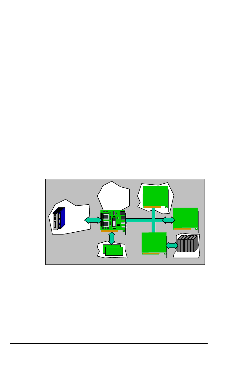
If you need more I/O, the MC includes a PC104 bus. Each MC can
accommodate as many as two PC104 cards. You can also add I/O to your
PC bus or other field buses such as DeviceNet and ProfiBus, and your
application controls it all. The figure below shows the various possible I/O
options.
SERVOSTAR
Auxillary I/O
SERCOS
SERVOSTAR MC
Standard I/O
PC-104
Mezzanine Bus
PC-104
I/O Cards
PC I/O Cards
PCI Bus
PC Field
Bus Cards
Field
Bus
Host CPU
Field I/O
1. 5 SERCOS
The SERCOS interface™ (developed in the mid-1980’s) provides an
alternative to the analog interface for communicating between motion
controllers and drives. In 1995, SERCOS became an internationally
accepted standard as IEC 1491 and later was continued to standard IEC
61491. The popularity of SERCOS has been steadily growing. All signals are
transmitted between controller and drives on two fiber optic cables. This
eliminates grounding noise and other types of Electro-Mechanical
Conductance (EMC) and Electro-Mechanical Interference (EMI).
M-SS-005-03 Rev E 3
Page 14
Overview 06/2005 Danaher Motion
Because SERCOS is digital, it can transmit signals such as velocity and
position commands with high resolution. The SERVOSTAR
®
MC and
accompanying drives ( SERVOSTAR CD series), support 32-bit velocity
commands. This provides a much higher resolution than can be achieved
with the analog interface. The most common SERCOS functions are
provided in such a way that you do not have to be an expert to gain the
benefits.
1. 6 API
DanaherMotion's Kollmorgen API is a software package that allows you to
communicate with the SERVOSTAR MC from popular programming
languages, such as Visual Basic. The API provides complete access to all
the elements of your system across dual-port ram. See the SERVOSTAR
SC/MC API Reference Manual for more information.
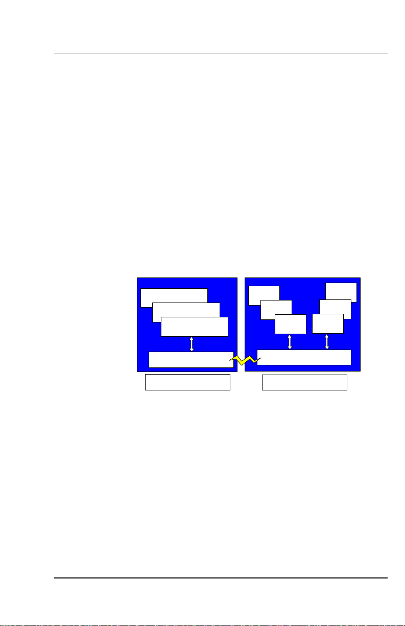
1. 7 MULTI-TASKING
The SERVOSTAR MC is a fully multi-tasking system (see figure below) in
which you can create multiple tasks and multiple elements (e.g., axes) that
operate independently of one another. Also, because the API supports
multiple applications communicating concurrently, you can write one or more
applications that have access to all of the tasks and elements.
3rd Party Soft PLC
Visual C
Visual BASIC
Kollmorgen API
Host CPU
Task 3
Task 2
Task 1
Dual Port RAM
SERVOSTAR MC
Axis 3
Axis 2
Axis 1
1. 8 USER COMMUNICATION
The ETHERNET and Serial ports of the MC are used for ASCII data transfer.
Non-printable characters are sent using CHR$. Data access is streamoriented. There is no data framing. MC Basic applications gain access to
either raw serial port or TCP socket. The TCP socket guaranties error free
data transfer, while the serial port does not offer error recovery. The
transmitted data does not have any meaning in terms of directly controlling
the MC.
User communication provides the basic features of serial and TCP/IP data
communication, which is not limited to a specific communication protocol,
enabling the usage of any protocol over serial or TCP/IP through an MC
application.
4 Rev E M-SS-005-03l
Page 15
Danaher Motion 06/2005 Overview
1.8.1. Serial Communication
The MC has two RS-232 ports, which can be used for user communication.
When COM1 is used for communication with BASIC Moves over API, tasks
cannot access it to eliminate interference with BMDS communications. Use
DIPswitch bit #8 to configure this port:
ON (default) COM1 is reserved for communication with the host and cannot
be used by any other application
OFF COM1 is available for user communication
DIP Switch bit #8 state
When DIPswitch bit # 8 is ON, the MC's firmware prints boot status
messages from COM1 using the following serial communication parameters:
Baudrate 9600 bps
Parity none
Stopbits 1
Databits 8
State ON of DIPswitch read as 0.
For example:
Switches 6 & 8 are OFF. All others are ON.
-->?sys.dipswitch bin
NOTE
0b10100000
-->
1.8.1.1. WITH HOST
When DIPswitch #8 is ON, the MC can communicate with the host via serial
port. This mode of communication requires Virtual Miniport driver, which is
installed during setup of BMDS. The driver simulates Ethernet connection
over serial interface using following fixed parameters:
Baudrate 115200 bps
Parity None
Stopbits 1
Databits 8
IP address 192.1.1.101
Subnet mask 255.255.255.0
All the parameters are fixed and cannot be modified.
If the driver is installed correctly and BMDS is running, it appears in the list of
Ethernet adapters as shown below:
C:\>ipconfig /all
Ethernet adapter Local Area Connection 5:
Connection-specific DNS Suffix . . . . :
Description . . . . . . . . . . . . . . : Giant Steps Virtual miniport
Physical Address. . . . . . . . . . . . : 00-02-1B-D1-A5-FC
DHCP Enabled. . . . . . . . . . . . . . : No
IP Address. . . . . . . . . . . . . . . : 192.1.1.1
Subnet Mask . . . . . . . . . . . . . . : 255.255.255.0
Default Gateway . . . . . . . . . . . . :
DNS Servers . . . . . . . . . . . . . . :
M-SS-005-03 Rev E 5
Page 16

Overview 06/2005 Danaher Motion
1.8.1.2. OPEN SERIAL PORT
Configurate the serial port with OPEN. Set the following port properties:
BaudRate - baud rate of the device set to a specified value.
Parity – enable/disable parity detection. When enabled, parity is odd or even.
DataBits - number of data bits.
StopBit - number of stop bits.
Xonoff – sets raw mode or ^S/^Q flow control protocol mode (optional parameter
disabled by default).
For example:
OPEN COM2 BUADRATE=9600 PARITY=0 DATABITS=8 STOPBIT=1 AS #1
Opens COM2 at 9600 bps baud-rate, No parity, 8-bit data, 1 stop bit.
OPEN assigns a device handle to the communication port. Any further
references to the communication port uses the device handle number. The
device handle range is 1…255. To change the communication parameters,
close the serial port and reopen it using the new parameters. For more
information, see PRINT # and INPUT$.
1.8.2. TCP/IP Communication
Use TCP/IP communication with other computers and intelligent I/O devices
over the Ethernet network. MC-BASIC uses TCP/IP API (sockets).
TCP/IP provides multi-thread communications. The same physical link
(Ethernet) is shared between several applications. This way, the MC can
connect to BASIC Moves and one or more intelligent I/O devices.
The MC supports both client and server roles for TCP/IP communications.
The TCP/IP client connects to a remote system, which waits for a connection
while the TCP/IP server accepts a connection from a remote system.
Usually, the MC serves as client while interfacing to an intelligent I/O
connected to the LAN, and as a server when working toward remote host like
a software PLC. The MC uses Realtek RTL8019AS Ethernet NIC at a bit rate
of 10 M bps.
1.8.2.1. SETUP
TCP communication starts by opening a socket either to connect to a remote
computer (remote host) or accept a connection from a remote host. Use
CONNECT or ACCEPT, depending on the MC functionality (client or server).
OPENSOCKET creates a TCP socket and assigns the socket descriptor to
the specified device handle. The socket is created with OPTIONS
NO_DELAY (send data immediately= 1). Otherwise, the data is buffered in
the protocol stack until the buffer is full or a time-out is reached. This
improves responsiveness when small amounts of data are sent. This option
is recommended for interactive applications with relatively small data
transfer. Otherwise, OPTIONS = 0.
OPENSOCKET OPTIONS=1 AS #1
OPENSOCKET assigns a device handle to the communication port (as
OPEN). Any further reference to the communication port uses the device
handle number. The device handle range is 1…255.
6 Rev E M-SS-005-03l
Page 17
Danaher Motion 06/2005 Overview
There are several ways to set the IP address of the controller. By default, the
MC boots without a valid IP address. The following options are available to
set the IP address of the controller:
Static IP address setting
Use SYS.IPADDRESSMASK in the Config.prg file to assign the IP
address and Subnet mask:
SYS.IPADDRESSMASK=”212.25.84.109:255.255.255.128”
Dynamic address setting by Windows API
API assigns an IP address to the MC when it establishes TCP
communication with the controller. The IP address and Subnet mask
are taken out of a pre-defined address pool. BASIC Moves uses this
address assigning method. Refer to the BASIC Moves Development
®
User Manual and SERVOSTAR® MC Reference Manual for
Studio
detailed information.
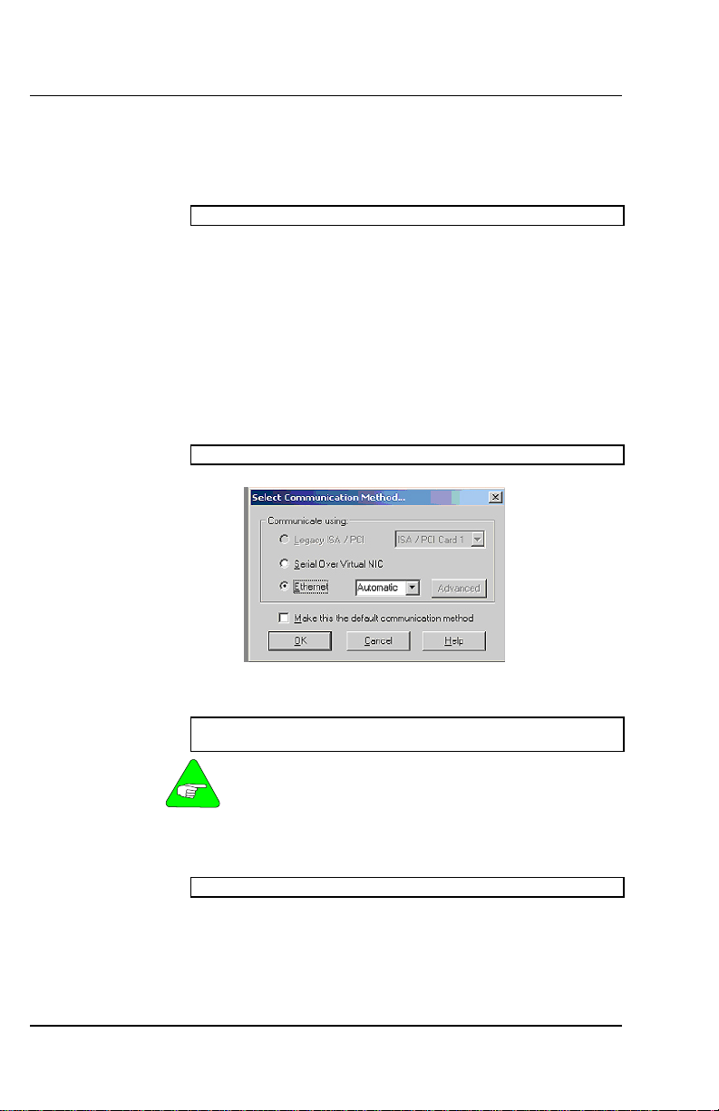
DHCP
IP address is assigned by the DHCP server. If your network does not
support DHCP, the controller tries to get the address from the DHCP
server and times out after few minutes. During that time, communication
with the controller is not possible.
SYS.IPADDRESSMASK=”dhcp”
If DHCP is used, select Automatic connection method as shown below:
Get the controller’s IP address
Use SYS.IPADDRESSMASK to query the IP address and Subnet mask
of the MC.
-->?SYS.IPADDRESSMASK
172.30.3.11:255.255.0.0
The MC has several IP interfaces: Ethernet, IP over serial and IP
over DPRAM. However SYS.IPADDRESSMASK is only valid fo r
Ethernet interfaces. Others have fixed IP addresses, which
NOTE
cannot be changed.
PING tests that a remote host is reachable. The remote host must
support ICMP echo request.
?PING(”212.25.84.109”)
1.8.2.2. MC AS TCP CLIENT
When acting as a client, the MC tries to connect to a remote server until a
time out value expires or the connection is rejected. Use CONNECT when
the MC acts as a client.
M-SS-005-03 Rev E 7
Page 18

Overview 06/2005 Danaher Motion
The MC requests a connection from a remote host, according to a specific IP
address and port. CONNECT blocks task execution until the connection is
established or until the command fails. To unblock a task waiting in
CONNECT, close the corresponding socket using CLOSE. In addition, killing
a task (KILLTASK) blocked by CONNECT closes the socket to release the
task. CONNECT may fail due to the following reasons:
1. Invalid socket descriptor
2. Remote host has no application attached to specified port.
3. Destination address is not reachable
The following example illustrates a typical procedure of establishing a
connection to a remote host, and sending and receiving data:
OPENSOCKET OPTIONS=0 AS #1
CONNECT (#1,”212.25.84.100”,6002)
PRINT #1,”HELLO”
?INPUT$(LOC(1),#1)
CLOSE #1
1.8.2.3. MC AS TCP SERVER
When acting as a server. the MC endlessly waits for a connection from the
remote host. Use ACCEPT when the MC acts as server. ACCEPT binds a
socket to a specified port and waits for a connection. Simultaneous
ACCEPTs on the same port are not allowed. ACCEPT blocks the execution
of the calling task until a connection is established. To unblock the task
waiting in ACCEPT, close the corresponding socket with CLOSE. In addition,
killing a task (KILLTASK) blocked in ACCEPT closes the socket and
releases the task. The following example illustrates a typical procedure of
waiting for a connection from a remote host, and sending and receiving data:
OPENSOCKET OPTIONS=0 AS #1
ACCEPT (#1,20000)
PRINT #1,”HELLO”
?INPUT$(LOC(1),#1)
CLOSE #1
1.8.3. Send /Receive Data
Serial and TCP communication use the same commands to send and
receive data. After establishing communication over TCP or after configuring
the serial port communication parameters, send and receive data regardless
the communication type. Data flow differences are communication speed
and the size of the input and output buffers. TCP/IP communication uses
larger communication buffers.
1.8.3.1. RECEIVE DATA
The input-buffer of the serial ports is a fixed512 bytes size. User
communication allows receiving strings using INPUT$. To check if data is
ready at the input buffer, use LOC. The following example checks the
number of bytes available at the input buffers and reads all the available
data:
-->?LOC(1)
11
-->STRING_VAR = INPUT$(11, #1)
-->?STRING_VAR
Hello World
8 Rev E M-SS-005-03l
Page 19

Danaher Motion 06/2005 Overview
If INPUT$ requests reading a data length larger than available data, the
command returns only the available data:
-->?LOC(1)
11
-->STRING_VAR = INPUT$(20, #1)
-->?STRING_VAR
Hello World
LOC can be used within the INPUT$:
STRING_VAR = INPUT$(LOC(1), #1)
A partial read of the input buffer is allowed. This way, several calls to
INPUT$ empty the input-buffer:
-->?LOC(1)
11
-->STRING_VAR = INPUT$(3, #1)
-->?STRING_VAR
Hel
-->?LOC(1)
8
-->STRING_VAR = INPUT$(8, #1)
-->?STRING_VAR
lo World
When calling INPUT$, the system does not wait for data. If the input-buffer is
empty, the command returns without any return value:
-->?LOC(1)
0
-->STRING_VAR = INPUT$(10, #1)
-->?len(STRING_VAR)
0
1.8.3.2. SEND DATA
PRINT # and PRINTUSING # send data over the serial port. Both
commands use the same formatting as PRINT and PRINTUSING.
PRINT # and PRINTUSING # appends a carriage-return (ASCII
value 13) and line-feed (ASCII value 10) characters at the end of
each message. To print a message without the terminating
NOTE
For example, the following uses PRINT # to send data:
-->STRING_MESSAGE = "ERROR"
-->PRINT #1, STRING_MESSAGE,"A1.PCMD=";A1.PCMD;
The output is:
ERROR A1.PCMD=0.000000000000000e+00
The values of the following variables are sent one after the other. The output
is (hexadecimal) 0x37 0x28:
I1=55
I2=40
PRINT #1, I1;I2
The output is:
5540
carriage-return and line-feed characters use a semicolon at the
end of the command.
M-SS-005-03 Rev E 9
Page 20
Overview 06/2005 Danaher Motion
1.8.3.3. SEND DATA BLOCK
PRINTTOBUFF # and PRINTUSINGTOBUFF # allows buffering of data
before actually being sent. This eliminates inter-character delays.
printtobuff #handle,chr$(0); chr$(message_length);
chr$(0);send=false
printtobuff #handle,chr$(request[ii]);send=false
printtobuff #handle,chr$(request[ii]);send=true
1.8.3.4. SEND/RECEIVE NULL CHARACTER
When using a specific protocol over Serial or TCP/IP ModBus RTU or
ModBus TCP), the NULL character is part of the message. The message
block cannot be saved in a STRING type variable since the NULL character
terminates the string.
To send a NULL character in a message, send the data as single bytes
instead of a string type message:
COMMON SHARED X[10] AS LONG
X[1]=0x10
X[2]=0
X[3]=0x10
PRINT #1, CHR$(X[1]);CHR$(X[2]);CHR$(X[3]);
The output is the following stream of bytes:
0x10, 0x0, 0x10
When the received data contains a NULL character, read the data from the
input buffer as single bytes instead of reading it into a string type variable.
Convert the incoming data to a numeric value to get its ASCII value:
DIM SHARED TEMP[10] AS DOUBLE
FOR IDX = 1 TO LOC(1)
TEMP[IDX] = ASC(INPUT$(1,#1))
NEXT IDX
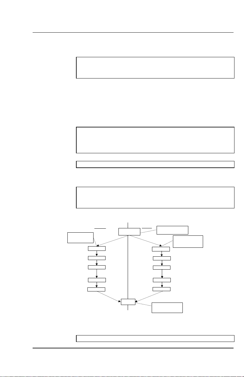
The figure below gives a general description of the TCP/IP communication
for both the client and host.
Client
Open TCP connection
(open socket)
Connect to specific
port and specific IP
address
Connect
Read
Write
Listen to specific
port and accept
connection
Server
Accept
Read
Write
Open Socket
Read
Write
Close
Read
Write
Close TCP connection
(close socket)
1.8.3.5. CLOSE CONNECTION
CLOSE closes the connection and releases the device handle:
-->CLOSE #1
10 Rev E M-SS-005-03l
Page 21
Danaher Motion 06/2005 BASIC Moves Development Studio
2. BASIC MOVES DEVELOPMENT STUDIO
BASIC Moves Development Studio (BMDS) provides Windows-based
project control for each application. BASIC Moves Development Studio
supports development for multi-tasking and also provides numerous tools
and wizards to simplify programming the MC.
BASIC Moves also provides modern debugging features such as allowing
task control by visually setting breakpoints, watch variables, and single
stepping. BASIC Moves automatically displays the data recorded on the MC
during operation. BASIC Moves provides all the tools you need for
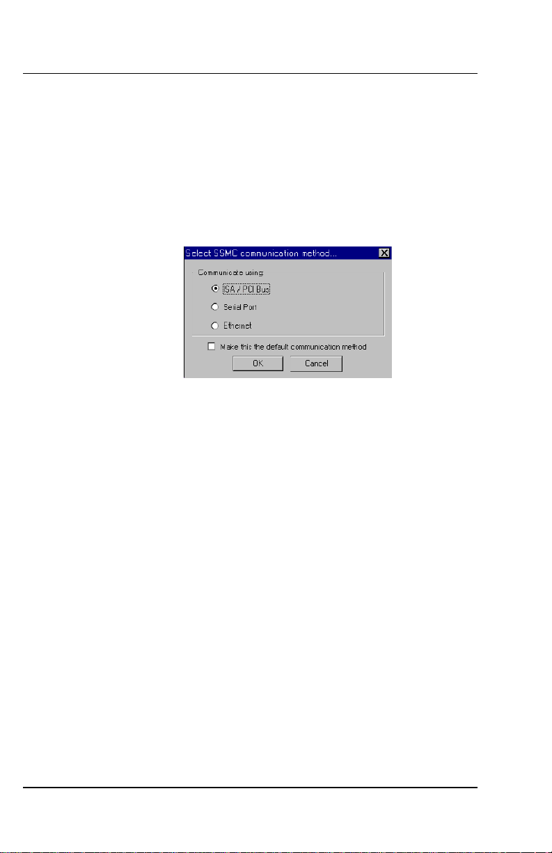
developing and debugging your application. When you start Basic Moves,
your first action is to select a method for communicating with your MC.
If you are using either a PCI or ISA model MC, choose ISA/PCI Bus. If you
are using a Stand-alone model MC, select either Serial Port or Ethernet
(communication method configured for your system). For more information
concerning communication with the stand-alone MC, refer to the Software
Installation section of the SERVOSTAR
MC Installation Manual.
2. 1 COMMUNICATION
Communicating with a stand-alone MC is not as automatic as is
comunicating with a PCI or ISA plug-in MC. Assuming you have properly
configured the communication method during installation of the BASIC
Moves Development Studio on your host computer, there are still some
operating procedures you may need to perform.
Ethernet
Serial
2. 2 MC-BASIC
The MC is programmed in MC-BASIC
the BASIC programming language enhanced for multi-tasking motion control.
If you are familiar with BASIC, you already know much of MC-BASIC. For
detailed information on any of the commands (including examples) used in
MC-BASIC, refer to the SERVOSTAR
M-SS-005-03 Rev E 11
If you configured Ethernet communications, subsequent communication
with the MC is automatically enabled and no further intervention is needed
unless you change the Ethernet network environment. If your network
environment changes, you may need to edit the IP address file. Refer to
the SERVOSTAR
The installation package includes the Virtual NIC device driver, which is
started automatically by Basic Moves Development Studio. No special
configuration is required. Refer to the SERVOSTAR
Manual for additional information.
MC Installation Manual for additional information.
MC Installation
® (
Motion Control BASIC), a version of
MC Reference Manual.
Page 22

BASIC Moves Development Studio 06/2005 Danaher Motion
To develop your application on the MC, you must install BASIC Moves
Development Studio. Refer to the software installation section of the
SERVOSTAR
MC Installation Manual for detailed instructions.
2.2.1. Instructions
Instructions are the building blocks of BASIC. Instructions set variables, call
functions, control program flow, and start processes such as events and
motion. In this manual we will use the terms instruction and command
interchangeably. For detailed information on any of the instructions (including
examples), refer to the SERVOSTAR
Syntax is the set of rules that must be observed to construct a legal
command (that is, a command the MC can recognize).
MC-BASIC is line-oriented. The end of the line indicates the end of the
instruction. Whitespace (i. e., spaces and tabs within the statement line and
blank lines), is ignored by the Basic interpreter. You can freely use
indentation to delineate block structures in your program code for easier
readability. The maximum allowed length of a line is 80 characters.
MC-BASIC is case insensitive. Commands, variable names, filenames, and
task names may be written using either upper case or lower case letters. The
only exception is that when printing strings with the “Print” and “PrintUsing”
commands, upper and lower case characters can be specified.
Syntax uses the following notation:
[ ] indicates the contents are required
{ } indicates the contents are optional for the command
Example lines of text are shown in Courier type font and with a border:
X = 1
MC Reference Manual.
2.2.2. Type
There are many types of instructions: comments, assignments, memory
allocation, flow control, task control, and motion. For detailed information on
any of the commands (including examples), refer to the SERVOSTAR
Reference Manual.
Comments allow you to document your program. Indicate a comment with
either the Rem command or a single apostrophe ('). You can add comments
to the end of an instruction with either Rem or an apostrophe.
Rem This is a comment
' This is a comment too.
X = 1 'This comment is added to the line X = 1
X = 1 REM This is a comment too
Use comments generously throughout your program. They are an asset
when you need support from others and they avoid confusing code.
Declarations allocate MC memory for variables and system elements
(groups, cam tables, etc.). This might be a simple type as an integer, or a
complex structure as a cam table.
Assignments Assignment instructions assign a new value to a variable.
The syntax of an assignment is
[Lvalue] [=] [expression]
For example:
X = Y + 1
12 Rev E M-SS-005-03l
MC
Page 23

Danaher Motion 06/2005 BASIC Moves Development Studio
The term, Lvalue, is a shorthand notation, which indicates the value to the
left of the equals sign. Valid Lvalues are variables or writable properties,
which can be assigned. Expressions can be variables, constants, properties
and function calls, as well as various combinations of them in arithmetic and
logical statements . An exception to this rule is generic elements’
assignment, at which the right side of the equal sign is not an expression, but
an axis or a group (either real or generic), and Lvalue is a generic elements.
If you assign a Double (floating point) value (expression, variable or
constant) to a Long variable, the fractional portion of the double value is
truncated, and the integer portion is assigned to the long variable. To query a
variable or expression from the BASIC Moves terminal window, use the
PRINT or ? command:
PRINT 1/100
? X1
MC-BASIC also provides the standard PRINTUSING (PrintU) command for
formatted printing.
Commands for flow control change the way your program is executed.
Without flow control, program execution is limited to processing the line
immediately following the current command. Examples of flow control include
GOTO, FOR…NEXT, and IF…THEN.
MC-BASIC is a multi-tasking language in which many tasks can run
concurrently. Generally, tasks run independently of each other. However,
tasks can control each other using inter-task control instructions. One task
can start, idle, or terminate another task.
Most commands are started and finished immediately. For example:
x = 1 ' this line is executed completely…
y = 2 ' …before this line is started
For general programming, one command is usually finished before the next
command starts. Effects of these commands do not persist beyond the time
required to execute them. However, the effects of many other commands
persist long after the execution of the command. In general programming, for
example, the effects of opening a file or allocating memory persist
indefinitely. In real-time systems, persistence is more complicated because
the duration of persistence is less predictable.
Consider a command that specifies a 1,000,000 counts move on an axis
named, A2:
Move A2 1000000.0
Y = 2
The MC does not wait for the 1,000,000 move to be complete before
executing Y=2. Instead, the first command starts the motion and then the MC
continues with the next line (Y = 2). The move continues well after the move
command has been executed.
Persistence can affect programs. For example, you may not want to start one
move until the previous move is complete. In general, you need access to
persistent processes if you are to control your program according to their
state of execution. As you will see later, MC-BASIC provides this access.
M-SS-005-03 Rev E 13
Page 24

BASIC Moves Development Studio 06/2005 Danaher Motion
2.2.3. Constants and Variables
All constant, variable and system element names must start with an
alphabetical character (a-z, A-Z) and may be followed with up to 31
alphabetical characters, numbers (0-9) and underscores (“_”). Keywords
may not be used as names. For detailed information on any of the constants
and variables (including examples), refer to the SERVOSTAR
MC
Reference Manual.
2.2.3.1. CONSTANTS
Constants are numbers, which are written as ordinary text characters; for
example, 161. Constants can be written in decimal or in hexadecimal (HEX).
To write a constant in hex, precede it by a 0x; for example, 0xF is the hex
representation of 15 decimal.
The MC provides numerous literal constants (reserved words with a fixed
value). You can use these constants anywhere in your program to make your
code more intuitive and easier to read. For example:
A1.Motion = ON
turns on the A1 property Motion. This is more intuitive to read than:
A1.Motion = 1
although the effect is identical.
2.2.3.1.1 Literal Constants Table
ABORT = 4 NEGATIVE = -1
ABOVE = 2 NEXTMOTION or NMOT = 2
BELOW = 1 NOFLIP = 1
CAM = 2 NOOVERLAP = 0
CAPTURING = 16 NOTELEVEL = 3
CLEARMOTION or CMOT = 3 OFF = 0
CLOSE = 0 ON = 1
CONTINUE or CONT = 1 ONPATH = 2
ENDMOTION or EMOT = 3 OPEN = 1
ERRORLEVEL = 2 OVERLAP = 1
EXTERNAL = 1 PI = 3.14159265359
FALL = 2 POSITIVE = 1
FALSE = 0 RESTART = 1
FAULTLEVEL = 1 RIGHTY = 2
FLIP = 2 RISE = 1
GEAR = 1 SILENTLEVEL = 0
GENERATORCOMPLETED or GCOM = 3 SUPERIMMEDIATE or SIMM = 5
HALT = 0 SYNC = 4
HOMING = 10 TASK_ERROR = 4
IDN_CAPTURE1ENABLE = 405 TASK_IGNORE = -1
IDN_CAPTURE1POSITIVELATCHED = 409 TASK_INCORRECT = 9
IDN_CAPTURE1NEGATIVELATCHED = 410 TASK_INTERRUPTED = 0x200
IMMEDIATE or IMMED = 1 TASK_KILLED = 10
INPOSITION or INPOS = 2 TASK_LOCKED = 0x100
LEFTY = 1 TASK_READY = 7
MAXDOUBLE = 1.797693134862311e+308 TASK_RUNNING = 1
MAXLONG = 2147483647 TASK_STOPPED = 2
MINDOUBLE = -1.797693134862311e+308 TRACK = 3
MINLONG = -2147483648 TRUE = 1
MULTIPLE = 1
2.2.3.2. VARIABLES
You must declare a variable in MC-BASIC before you can it. In the
declaration, you define variable name, scope and variable type. MC-BASIC
supports Long for integer values, Double for floating point values, and String
for ASCII character strings.
14 Rev E M-SS-005-03l
Page 25

Danaher Motion 06/2005 BASIC Moves Development Studio
Besides these basic types, MC-BASIC also supports Structure-like variables
and some MC-BASIC specific types, such as points (Joints and Locations),
generic motion elements (Axes and Groups) and UEAs (user error
assertions-Errors and Notes).
DeleteVar deletes a global variable. Since variable name can include
wildcards, a single DELETEVAR can be used to delete more than one
variable.
DeleteVar int1
DeleteVar int* ' Deletes all variables starting with int
Current values of global variables (both scalar and arrays) can be stored in a
Prg file, in assignment format, within an automatically executable Program
Continue…Terminate Program block. Obligatory parameters of SAVE are
the name of storage file, and type of stored variables (could be all types).
Optional parameters are robot type (for point variables), variable name
(which may include wildcards) and mode of writing to storage file (overwriting
or appending). Variable types available for storage through SAVE are longs,
doubles, strings, joints and locations, but not structures, user-defined
exceptions nor generic motion elements.
Save File = “IntFile.Prg” Type = All VariableName = “int*”
‘ Save all variables starting with int in IntFile.Prg (overwrite file)
Save File = “Points.Prg” Type = Joint RobotType = XYZR Mode = Append
‘ Append all joint-type points with XYZR robot-type to Points.Prg file
Scope defines how widely a variable can be accessed. The broadest scope
is global. A global variable can be read from any part of the system software.
Other scopes are more restrictive, limiting access of variables to certain
sections of code. MC-BASIC supports three scopes: global, task, and local.
Task variables can be read from or written to anywhere within the task where
it is defined, but not from outside the task. Local variables can only be used
within their declaration block, i.e. program, subroutine or function blocks. The
scope of a variable is implicitly defined when a variable is declared using the
keywords: Common, Shared, and Dim.
Global variables can be defined within the system configuration task,
Config.Prg, within a task files (Prg files), before the program block, within
library files (Lib files), before the first subroutine or function block, or from the
terminal window of BASIC Moves. To declare a variable of global scope use
the Common Shared instruction.
Task variables are defined within a task or a library. To declare a variable of
task scope use the Dim Shared instruction.
All Dim Shared commands must appear above the Program
statement in task files. In library files, all Dim Shared commands
must appear above the first block of subroutine or function. The
values of variables declared with Dim Shared persist as long as the
task is loaded, which is usually the entire time the unit is
NOTE
operational. This is commonly referred to as being static.
Local variables are defined and used within a program, a subroutine, or a
function. To declare a local variable, use the Dim instruction. The Dim
command for local variables must be entered immediately below the
Program, Sub, or Function statement. Local variables cannot be declared
within event blocks, and events cannot use local variables declared within
the program.
M-SS-005-03 Rev E 15
Page 26

BASIC Moves Development Studio 06/2005 Danaher Motion
2.2.4. Data Types
MC-BASIC has two numeric data types: Long and Double. Long is the only
integer form supported by MC-BASIC. Long and Double are MC-BASIC's
primitive data types.
Type Description Range
Long 32 bit signed integer -2,147,483,648 (MinInteger)to
Double Double precision floating point
(about 16 places of accuracy)
MC-BASIC provides the string data type which consists of a string of ASCIIcoded characters. MC-Basic strings are dynamic. Reallocation of memory for
new strings is preformed through a simple assignment of the string variable,
and there is no need to specify the length of the new string. A full
complement of string functions is provided to create and modify strings.
Type Description Range
String ASCII character string (no string length limit) 0 to 255 (ASCII code)
MC-BASIC has two point data types: JOINT and LOCATION. A point
variable is related to a robot type. Robot type examples: XY – two axes XY
table, XYZ – three axes XYZ system, XYZR – three cartesian axes + roll, etc.
Type Description Range
Joint A set of 2-10 double precision
Location A set of 2-10 double precision
floating point joint (motor)
coordinates
floating point cartesian coordinates
MC-Basic enables definition of structure-like data types, composed of a
limited number of long, double, string and point (joint and/or location) scalar
and array elements. Array elements can have only a single dimension. Name
of structure type and composition of elements are defined by the user within
configuration file (Config.Prg).
Type Description Range
0-100 longs 32 bit signed integer -2,147,483,648 (MinInteger) to
0-100 doubles Double precision floating point
0-100 strings ASCII character string (no
0-100 points
(joints and/or
locations)
0-10 long
arrays
0-10 double
arrays
0-4 string
arrays
1-2 point
(joints and/or
locations)
arrays
(about 16 places of accuracy)
practical limit to string length)
A set of 2-10 double precision
floating point coordinates
1-32,767 32 bit signed integers -2,147,483,648 (MinInteger) to
1-32,767 double precision
floating point elements
1-32,767 ASCII character
strings
1-32,767 sets of 2-10 Double
precision floating point
coordinates
2,147,483,647 (MaxInteger)
±1.79769313486223157 E+308
±1.79769313486223157 E+308
for each coordinate
±1.79769313486223157 E+308
for each coordinate
2,147,483,647 (MaxInteger)
±1.79769313486223157 E+308
0 to 255 (ASCII code)
±1.79769313486223157 E+308
for each coordinate
2,147,483,647 (MaxInteger)
±1.79769313486223157 E+308
0 to 255 (ASCII code)
±1.79769313486223157 E+308
for each coordinate
16 Rev E M-SS-005-03l
Page 27

Danaher Motion 06/2005 BASIC Moves Development Studio
MC-Basic has two UEA (user error assertion) data types (severities): Error
and Note. Each UEA is defined with a string-type error message given by the
user and a unique exception number, which might be determined either by
the user or by the system. The SERVOSTAR
MC handles UEAs similar to
internal exceptions.
Type Description Range
Error An ASCII message string and a
unique integer exception
number
Note An ASCII message string and a
unique integer exception
number
20001-20499 for user determined
exception number
20500-20999 for system determined
exception number
20001-20499 for user determined
exception number
20500-20999 for system determined
exception number
MC-Basic provides generic element data types designed to serve as a
reference to real axes and groups. Through a simple assignment statement,
the generic element gets the element identifier (see below) of a real motion
element, thus acquiring all its properties. Afterwards, all activities preformed
on the generic element identically affect the real element. The referenced
element can be changed, through recurring assignments, as many times as
the user wishes.
Type Description Range
Generic Axis An integer element
Generic Group An integer element
identifier
identifier
0 (before first assignment)
1 to number of axes in system (up
to 32)
0 (before first assignment)
33 to number of groups in system
(up to 64)
Each real motion element gets a unique element identifier from the system
during its declaration. Axes get successive element identifiers ranging from 1
to 32 according to axis number. Groups get successive identifiers ranging
from 33 to 64 according to declaration order. Value of element identifier can
be queried directly through ELEMENTID.
SYS.NUMBERAXES = 2
Common Shared G2 As Group AxNm = A1 AxNm = A2
Common Shared G1 As Group AxNm = A1 AxNm = A2
? A1.ELEMENTID
1
? A2.ELEMENTID
2
? G2.ELEMENTID
33
? G1.ELEMENTID
34
MC-BASIC uses integers to support Boolean (logical) operations. Logical
variables have one of two values: true or false. MC-BASIC uses type Long to
support logical expressions. The value 0 is equivalent to false. Usually, 1 is
equivalent to true, although any non-zero value is taken to be true. Boolean
expressions are used in conditional statements such as If…Then, and with
Boolean operators like And, Or, and Not.
Arrays can be any data type. Arrays may have from 1 to 10 dimensions. The
maximum number of elements in any dimension is 32,767. Array dimensions
always start at 1.
M-SS-005-03 Rev E 17
Page 28

BASIC Moves Development Studio 06/2005 Danaher Motion
2.2.4.1. STRUCTURES
A structure is a new data type used for storing a list of variables of different
type in one variable.
2.2.4.1.1 Definition
Since a structure is a user-defined data type; it must first be defined.
Structure type definition can be done only in the Config.prg file (before the
PROGRAM block, at the declaration level), using the following syntax:
TYPE <structure_type_name>
<element_name>{[]} AS <element_type> {OF <robot_type>}
…
END TYPE
This block defines the name of the structure type and the names, types and
array sizes of the various structure elements (fields). Data types supported
as structure elements are: long, double, string, and points (JOINT and
LOCATION). Array elements can only have a single dimension. The
maximum structure block can include: 100 longs, 100 doubles, 100 strings,
100 points JOINTs and/or LOCATIONs), 10 long-type arrays, 10 double-type
arrays, 4 string-type arrays and 2 point-type arrays JOINTs and/or
LOCATIONs). The total size of the MC-Basic structure is limited. The
maximum number of each type of element is fixed. Trying to define more
structure elements than allowed results in a translation error. An array of
structures may have up to 10 dimensions.
2.2.4.1.2 Declare
You must declare a structure before you can use it. If you want to declare a
structure variable, you must first declare a structure data type and then use
this data type structure to declare the variable. The structure data type
definition can be done in the Config.prg file only with the following syntax
(before the PROGRAM token, at the declaration level):
TYPE <variable_name>
<variable_name> as <type>
<variable_name> as <type> {<of> <robot_type>}
…
END TYPE
This block defines the new element names of the structure type. The
different types supported for the structure are: long, double, string, and
points. The maximum structure block is defined as:
100 longs
100 doubles
100 strings
100 points
2.2.4.1.3 Syntax
(COMMON SHARED|DIM {SHARED}) <variable_name> AS <variable_name>
or
(COMMON SHARED|DIM {SHARED}) <variable_name>[<index>] AS
<variable_name>(arrays of structure)
where the second variable name = the structure type
18 Rev E M-SS-005-03l
Page 29

Danaher Motion 06/2005 BASIC Moves Development Studio
For example:
In config file ->
Type X
Type as Long
Length as Long
End Type
In application file ->
Dim shared s1 as X
Program
?s1->Type
End program
Do not define the size of the structure data type. The size of the structure is
constant. If you declare more structure elements than allowed, a translation
error is generated.
2.2.4.1.4 Assignment
The assignment of a structure uses the following syntax:
<variable_name> = <expression> where <expression> is of
structure type
Whole structure assignment is allowed only if both structures are of the same
structure type. For example:
Dim STa1 As Type_1
Dim STb1 As Type_1
Dim STa2 As Type_2
STa1 = STb1 -> Structure types match
STa2 = STa1 -> Error - structure type mismatch
2.2.4.1.5 Elements
A structure element is addressed through the structure’s name and the arrow
sign. For example:
<structure_name>{[]…}-><element_name>{[]}
Structure elements are handled almost like regular variables. Structure
elements are printed, assigned, participate in mathematical operations, and
string-type elements are concatenated to other strings. They can also serve
as arguments of system functions (SIN, UCASE$, etc.), used in logic
statements and as conditions of flow control statements and event
definitions. For example:
Common Shared ST As STRUCT
PRINT ST->LongElm1
ST->LongElm2 = 21.2 * ST->LongArrElm[1]
? UCASE$(“String Element Is: “ + ST->StringElm)
IF ST->LongElm1 > 0 THEN
SELECT CASE ST->LongElm2
2.2.5. System Elements
There are several system elements: axes, groups, cam tables, PLSs,
conveyers and compensation tables. These are not regular data types, but
are more like user interfaces of the system's internal memory or internal
function calls. You cannot handle them as a whole in expressions.
system element has a set of properties, which is accessed through syntax
resembling data elements of a structure, using the point character.
M-SS-005-03 Rev E 19
Each
Page 30

BASIC Moves Development Studio 06/2005 Danaher Motion
Despite the syntax, properties are not data elements, since a system
element and its properties are not located on a continuous block of memory.
All properties return a value, so they can be printed, combined in
expressions and passed by value to functions and subroutines. Many
properties are also writable and can be assigned like variables.
Unlike variables, properties do not have a fixed address in memory and
cannot be passed by reference. Data types of properties are Long, Double,
String, Joint and Location. For axis A1 and cam table Cam1, and a long type
variable named Var1:
? A1.Enable ‘ Query
A1.Enable = 1 ‘ Set (read-write property)
? A1.PositionCommand ‘ Query
A1.PositionCommand = 0 ‘ Syntax Error (read-only property)
Var1 = Cam1.Cycle ‘ Query
Cam1.Cycle = -1 ‘ Set (read-write property)
Var1 = Cam1.Inuse ‘ Query
Cam1.Inuse = 1 ‘ Syntax Error (read-only property)
2.2.6. Units
Many variables have associated units. This include variables, which contain
quantities of position, velocity, acceleration, and time. Some units are fixed.
For example, time is always in milliseconds. MC-BASIC allows you to define
units of position, velocity and acceleration independently. In the next chapter,
we will discuss how to set up units.
2.2.7. Expressions
Expressions are combinations of operators and value-returning entities, such
as variables, constants, function calls, which are all calculated into a value.
In MC-Basic, expressions can also contain unique entities like element
properties (see above) and system properties (see below). Operators (like +
and -) specify how to combine the variables and constants. Expressions are
used in almost all commands.
An expression has one of two syntax forms
[operand] [binary operator] [operand]
[unary operator] [operand]
An operand can be a constant (123.4), variable name (X), or another
expression. Most operators are binary (they take two operands), but some
are unary (taking only one operand). So, -5.5 is a valid expression. It has the
unary minus (also called negation) and a single operand.
There are two types of expressions: algebraic and logical (or Boolean).
Algebraic expressions are combinations of data and algebraic operators.
The results of all algebraic operations are converted to double precision
floating-point after executing the expression.
2.2.8. Automatic Conversion of Data Types
If the assignment of an expression is an integer, the expression is still
evaluated in double precision. For example:
Common Shared I as Long
I = 6.33 * 2.79
20 Rev E M-SS-005-03l
Page 31

Danaher Motion 06/2005 BASIC Moves Development Studio
The value of the expression (6.33 * 2.79) is converted from double to long
when the value (17) is copied into I. In the conversion to long, the number is
truncated to the integer portion of the floating-point value.
Logical expressions are combinations of data and logical operators. For
example, X1 And X2 is a logical expression. The data and results of logical
elements are type Long. Double variables are not allowed in logical
expressions. The terms, logical and Boolean are considered
interchangeable.
Logical expressions are evaluated from left to right. They are evaluated only
far enough to determine the result. So, in A And B And C, if A is 0 (false),
the result is false without evaluating B or C.
Precedence dictates which operator is executed first. If two operators
appear in an expression, the operator with higher precedence is executed
first. For example, multiplication has a higher precedence than addition. The
expression
1+2*3 is evaluated as 7 ((2 * 3) + 1), not 9 ((2 + 1) * 3).
The minus sign in the math operators’ table (below) is sometimes confusing
since it shows up twice in the table: once with a high precedence (unary
negation) and once with low precedence subtraction (binary minus). This
difference in precedence is intuitive:
5 * -6 only makes sense if the
negation is executed first.
The tables that follow list different types of operators. The entries in the
tables are listed in order of precedence: the higher in the table, the higher the
operator precedence. Also, the tables themselves are arranged in order of
precedence with respect to one another. Math operators have the highest
precedence. So, all math operations are executed before any other type of
operator is executed. Finally, any time you need to change the standard
precedence, use parentheses. Parentheses have the highest precedence of
all.
Algebraic Operator Symbol Unary/Binary Operand Type
Parentheses ( ) NA double, long, string, joint, location
Exponentiation ^ Binary double, long
Negation - Unary double, long, joint, location
Unary Plus + Unary double, long, joint, location
Multiplication * Binary double, long, joint, location
Division / Binary double, long, joint, location
Modulo Mod Binary double, long
Addition + Binary double, long, string, joint, location
Subtraction - Binary double, long, joint, location
Compound : Binary location
Relational Operator Symbol Binary/Unary Operand Type
Parentheses ( ) Not applicable double, long, string
Equality = Binary double, long, string
Inequality <> Binary double, long, string
Less than < Binary double, long, string
Greater than > Binary double, long, string
Less than or equal to <= Binary double, long, string
Greater than or equal to >= Binary double, long, string
Word-wise Logical Operator Symbol Unary/Binary Operand Ty pe
And And Binary long
Or Or Binary long
Exclusive or Xor Binary long
Not Not Unary long
M-SS-005-03 Rev E 21
Page 32

BASIC Moves Development Studio 06/2005 Danaher Motion
Bit-Wise Logical Operator Symbol Unary/Binary Operand Type
Bitwise Negation BNot Unary long
Bitwise And BAnd Binary long
Bitwise Or BOr Binary long
Bitwise Xor BXor Binary long
Shift Left SHL Binary long
Shift Right SHR Binary long
Negation is simply placing a minus sign in front of a constant or variable to
invert its arithmetic sign. Modulo division produces the remainder of an
addition. For example,
82 Mod 5 is equal to 2 (the remainder of 82/5). If the
first operand is negative, the resultant value is negative (-2). The sign of the
result is determined by the sign of the first operand, and the sign of the
second operand has no effect.
The relative precedence of exponentiation and negation may seem
somewhat counter-intuitive. The following examples illustrate the actual
behavior.
Common shared D as double
D = -1
? D^2
1
? -1^2
-1
In the second section of the above example, exponentiation is performed first
then negation is performed.
Common shared D as double
D = -1
? D = -1
1
In the example above, the “=” sign is taken as a relational operator (i.e., Is D
= -1?) The relation is True, or 1.
? D^2 = -1^2
0
In the example above, the “=” sign is taken as a relational operator, (i.e.,
Is D^2 = -1^2?). Again, the exponentiation is performed first, and then the
relation is evaluated as False, or 0.
The "+" operator, when used with strings, performs concatenation of strings.
In points, “+” (addition) and “-“ (subtraction) operators can be used between
points of the same type and size, or between a point and a long or double
type scalar. On the other hand, “*” (multiplication) and “/” (division) operators
can only be operated between a point and double or long scalar, but not
between two points.
In Logical operations, every value that is not 0 is assumed true and set to 1.
And-ing combines two values so the result is true (1) if both values are true
(that is, non-zero). Or-ing combines them so the result is true (1) if either
value is true. Exclusive-Or produces true if one or the other value is true. It
produces false (0) if both or neither are true. Before logical operations begin,
all operands are converted to 1 (true) or 0 (false). The rule is that everything
that is not 0 becomes 1.
22 Rev E M-SS-005-03l
Page 33

Danaher Motion 06/2005 BASIC Moves Development Studio
Bit-wise expressions differ from logical expressions in that there may be
many results from a single operation. Bitwise operations are frequently used
to mask I/O bits. For example, the standard SERVOSTAR MC inputs can be
operated on with BAnd (Bitwise And) to mask off some of the inputs. The
following example masks off all bits of the digital outputs, except the
rightmost four:
Dim Shared MaskedBits As Long
MaskedBits = System.Dout Band 0xF
‘Mask all but rightmost four bits
All bitwise operations produce 32-bit result from two 32-bit numbers. Bitwise
operations are really 32 independent, bit-by-bit operations. For example:
15 (Binary 1111) BAnd 5 (Binary 101) is 5 (Binary 101)
BNot 15 is 0xFFFFFFF0.
2.2.9. Math Functions
MC-BASIC provides a large assortment of mathematical functions. All take
either numeric type as input (Double and Long) and all but Int and Sgn
produce Double results. Int and Sgn produce Long results. For detailed
information on any of the math functions (including examples), refer to the
SERVOSTAR
Abs(x) Returns the absolute value of X.
Acos(x) Returns the arc cosine of X. X is assumed to be in radians.
Asin(x) Returns the arc sine of X. X is assumed to be in radians.
Atan2(Y, X) Returns the inverse tangent of Y/X in radians. The range of the result is
Atn(X) Returns the inverse tangent of X in radians. The range of the result is
Cos(X) Returns the cosine of X. X is assumed to be in radians.
Exp(X) Returns ex.
Int(X) Returns the largest long value less than or equal to a numeric
Log(X) Returns the natural logarithm of X. X must be > 0. If you want the base-
Sgn(X) Returns the arithmetic sign of X. If X > 0, return 1. If X < 0, return -1. If X
Sin(X) Returns the sine of X. X is assumed to be in radians.
Sqrt(X) Returns the positive square root of X. X must be >= 0.
Tan(X) Returns the tangent of X. X is assumed to be in radians.
Round(X) Returns the integer nearest to X. If X falls exactly between two integers
MC Reference Manual.
between ±PI radians (±180°). Atan2 is an improvement over ATN(Y/X)
in that it works correctly if X is zero, and if X<0.
between PI/2 radians ( 90).
expression (for example, ?Int(12.5) returns 12
?Int(-12.5) returns -13)
10 log, use Y = LOG(X)/LOG(10).
= 0, return 0.
(for example, 1.5), return the even integer. So 1.5 and 2.5 round to 2.
M-SS-005-03 Rev E 23
Page 34

BASIC Moves Development Studio 06/2005 Danaher Motion
2.2.10. String Functions
Beginning with version 3.0, MC-BASIC supports all the common string
functions supported in standard BASIC. For detailed information on any of
the string functions (including examples), refer to the SERVOSTAR
Reference Manual.
ASC(S,I) Returns an ASCII character value from within a string, S, at
position, I.
BIN$(X) Returns the string representation of a number (X) in binary
format (without the Ob prefix).
CHR$(X) Returns a one-character string corresponding to a given ASCII
value, X.
HEX$(X) Returns the string representation of a number (X) in
hexadecimal format (without the 0x prefix).
INSTR(I,SS,S) Returns the position, I, of the starting character of a substring,
SS, in a string, S.
LCASE$(S) Returns a copy of the string, S, passed to it with all the
uppercase letters converted to lowercase.
LEFT$(S,X) Returns the specified number, X, of characters from the left-
hand side of the string, S.
LEN(S) Returns the length of the string, S.
LTRIM$(S) Returns the right-hand part of a string, S, after removing any
blank spaces at the beginning.
MID$(S,I,X) Returns the specified number of characters, X, from the string,
S, starting at the character at position, I.
RIGHT$(S,X) Returns the specified number of characters, X, from the right-
hand side of the string, S.
RTRIM$(S) Returns the left-hand part of a string, S, after removing any
blank spaces at the end.
SPACE$(X) Generates a string consisting of the specified number, X, of
blank spaces.
STR$(X) Returns the string representation of a number, X.
STRING$(X,{S},{Y}) Creates a new string with the specified number, X, of characters,
each character of which is the first character of the specified
string argument, S, or the specified ASCII code, Y.
UCASE$(S) Returns a copy of the string, S, passed to it with all the
lowercase letters converted to uppercase.
VAL(S) Returns the real value represented by the characters in the input
string, S.
MC
24 Rev E M-SS-005-03l
Page 35

Danaher Motion 06/2005 BASIC Moves Development Studio
2.2.11. System Commands
The following commands provide information about the system. You can
issue these commands at any time either from task, terminal or the
CONFIG.PRG file (with some exceptions). For detailed information on any of
the system commands (including examples), refer to the SERVOSTAR
Reference Manual.
AxisList Returns a comma-separated-list of the axes' names
defined in the system. If wildcards are used, the query
returns the proper axes.
BreakPointList Lists all the breakpoints in the task, loaded to memory.
CamList This query returns a list of the cam table names defined in
the system. If wildcards are used, the query returns the
proper existing cam names.
Dir Lists all files that exist on the RAM disk and on the Flash
disk. The File Specification may contain the * and ?
wildcard characters, in order to refine the list. When
invoked without a parameter, all the files are listed.
ErrorHistory Displays the log file containing the last 64 errors that
occurred in the system.
ErrorHistoryClear Clears the error log file.
EventList Lists the names of the existing events and their states. If a
task name precedes EventList, only events belonging to
the specified task are listed.
GroupList Lists the names of the groups defined in the system. Each
group name is followed by a list of the axes' names that
are part of that group.
PlsList Returns a list of the PLS names defined in the system. If
wildcards are used, the query returns the correct existing
PLS data.
ProgramPassword Sets the file password and toggles the password
protection state.
Reset All | Tasks Reset All removes all tasks, variables, and system
variables from program memory. All external outputs are
turned off and all drives are disabled. Reset All runs
Config.prg, not Autoexec.prg. Reset All is only issued
from the terminal.
Reset Tasks removes all tasks from memory, but leaves
system variables loaded. It deallocates all defined
variables and user programs. Reset Tasks does not
disable motors, or reset outputs. Reset Tasks is only
issued from the terminal.
System.AccelerationRate Queries or sets the system acceleration exchange rate.
System.AutostartTask Queries or sets the name of the auto-start task. The
default auto-start task is Autoexec.Prg. Assignment of an
empty string prevents auto-start task run.
System.AverageLoad Returns the average realtime load on the CPU. This is the
average realtime load measured during a 0.5 second
interval.
System.Clock Returns the number of system clock ticks. This is the clock
run by the VxWorks Operating System. One clock tick
corresponds to 1 millisecond.
System.CpuType Returns the type and model of the CPU that was found
during the system’s power-up. Supports only Intel, AMD
and Cyrix processors.
System.Date Queries or sets the date. The date is entered as a
character string and must be enclosed between double
quotes ("). The parameters Day, Month, and Year, must
be separated with the / (slash) character.
MC
M-SS-005-03 Rev E 25
Page 36

BASIC Moves Development Studio 06/2005 Danaher Motion
System.DecelerationRate Queries or sets the system deceleration exchange rate.
System.DIn Returns the value of one or more of the 23 digital inputs.
System.DipSwitch Returns the value of one or more of the eight DIPswitch
System.DiskFreeSpace Returns the amount of free space on the flash disk.
System.DoubleFormat Queries and sets the printing format of Doubles. Zero
System.DOut Queries and sets the value of one or more of the 20
System.Enable Enables and disables the system.
System.Error Queries the last system error message.
System.ErrorHandlerMode Determines the scope of the effect of an error occurring
System.ErrorNumber Queries the number of the last system error and returns
System.ErrorPrintLevel Controls which errors are printed, according to the
System.FlashDiskSize Returns the size of the Flash disk.
System.HostDouble Reads the value of one of eight double-type DPRAM
System.HostInteger Reads the value of one of eight long-type DPRAM
System.Information Returns information found during system power-up.
System.IPAddressMask Queries or sets the IP address and subnet mask for the
System.JerkRate Queries or sets the system jerk exchange rate.
System.Led Queries and sets one or more of the three general
System.MaxMemBlock Returns the size (in bytes), of the largest block of free
System.MCDouble Reads or writes to one of eight double-type DPRAM
System.MCInteger Reads or writes to one of the long-type DPRAM
System.Motion Enables and disables Motion commands.
System.DIn returns the values of the individual bits in
the system input word. In order to read the value of a
single input bit, bit number should be specified as
System.DIn.<bit number>.
inputs. System.DipSwitch returns the values of the
eight individual bits in the DIPswitch byte. In order to
read the value of a single input bit, bit number should be
specified as System.DipSwitch.<bit number>.
value stands for d.ddddddddddddddde+/-dd style, with
precision of 15 digits after the decimal point. 1 relates to
the ddd.ddd style if the exponent is between -4 and 5,
and to d.de+/-dd style otherwise. Setting can be done
only in Config.Prg file, and therefore requires system
reset (through RESET All or hardware reset).
digital outputs. System.DOut sets or returns the values
of the individual bits in the system output word.
to read or write into a single output bit, bit number should
be specified as System.DOut.<bit number>.
in task context. When the value of
System.ErrorHandlerMode is one (the default value),
the error will affect the entire system by stopping all
motion, idling all tasks that have attached elements and
turning off System.Motion flag. Setting this property to
zero results in limiting the Motion stop and task idling to
the erroneous task itself.
only the error number.
severity of the error. Only asynchronous errors are
printed. Synchronous errors are not affected.
variables written by the host.
variables written by the host.
Performs a test on the SERCON chip cycle time. The
result is the average cycle time found in a 500 ms test.
Ethernet interface.
purpose LEDs. In order to read or write into a single
LED, LED number should be specified as
System.LED.<LED
memory.
variables available for use by the MC.
variables available for use by the MC.
number>.
In order
26 Rev E M-SS-005-03l
Page 37

Danaher Motion 06/2005 BASIC Moves Development Studio
System.MotionAssistance Enables and disables display of additional notes
System.Name Queries and sets t he name of the controller.
System.NoMotion Enables and disables the System.Motion
System.NumberAxes Returns the number of axes currently loaded in the
System.PeakLoad Returns the peak realtime load on the CPU. This is
System.PipeMode Queries and sets the type of motion pipe mode.
System.PrintMode Queries and sets the printing format of Longs.
System.RamDriveFreeSpace Returns the amount of free space on the RAM
System.RamSize Returns the size of the RAM found during the
System.RtsTimeout Queries and sets the timeout of the real-time
System.SerconVersion Returns the version number of the SERCON chip.
System.SerialNumber Returns the serial number of the MC.
System.ServicePrintLevel Controls (query or set) printing of service
System.Time Queries or sets the current time of day. Hours,
System.UserAuthorizationCode Returns the user authorization code.
System.VelocityOverride Queries or sets the system velocity override.
System.VelocityRate Queries or sets the system velocity exchange rate.
System.VIn Returns the value of one or more of the 32 virtual
System.VOut Queries and sets the value of one or more of the
System.WatchDogTest Checks the correct operation and timeout of the
TaskList Lists the names and states of loaded tasks.
VarList Returns a list of the variable names defined in the
Version Returns information pertaining to the version of
returned from the motion task.
monitoring apparatus.
system. This is a read-only variable. It can be used
in the terminal window or in any task.
the maximum value of the realtime load measured
during a 0.5 second interval.
Available types are: active, position only, or
position and velocity.
Optional formats are DECIMAL (decimal format),
HEX (hexadecimal format) and BIN (binary
format). Default format is decimal.
drive.
system power-up.
scheduler.
messages (ON or OFF).
minutes, and seconds are each specified using
two digits. The MC uses 24-hour clock notation.
Time is entered as a character string and must be
enclosed between double quotes ("). The
parameters, Hours, Minutes, and Seconds, must
be separated with : (colon) characters.
inputs. System.VIn returns the values of the
individual bits in the system input word. In order to
read the value of a single input bit, bit number
should be specified as System.VIn.<bit number>.
32 virtual outputs. System.VOut sets or returns
the values of the individual bits in the system
output word.
output bit, bit number should be specified as
System.VOut.<bit number>.
WatchDog. After the test has finished, the MC
must be rebooted. The test returns either the WD
timeout (in ms) when executed successfully, or an
error in case of a test failure.
system.
BASIC Moves Development Studio loaded into
your MC.
In order to read or write into a single
M-SS-005-03 Rev E 27
Page 38

BASIC Moves Development Studio 06/2005 Danaher Motion
With…End With Simplifies blocks of code, which set a number of parameters on
the same motion element (axis or group). After a With is
encountered, all parameters where the element is not specified
are assumed to belong to the element specified in the With.
With is valid in Configuration, Task, or Terminal contexts. The
scope of a configuration With is global, whereas the scopes of
both terminal and task With’s are limited to terminal and task,
respectively.
To put off the With’s effect, use End With. A task With must be
followed by the End With, thus creating a closed With block. A
With block must be closed within the same block it was opened
(i.e., Program, Sub and Function blocks). For example:
A1.VMax = 5000
A1.Vord = 5000
A1.VCruise = 3000
A1.PEMax = 10
A1.PESettle = 0.01
Move A1 100
Can be simplified using With:
With A1
VMax = 5000
Vord = 5000
VCruise = 3000
PEMax = 10
PESettle = 0.01
Move 100
End With
2.2.12. Printing
MC-BASIC provides unformatted and formatted printing using the PRINT
and PRINTUSING commands. For detailed information on any of the print
commands (including examples), refer to the SERVOSTAR
Manual.
The Print command (short form, ?) is used to print expressions from the
terminal window or from your program. If you issue print commands from the
terminal window, they print to the terminal window. If you issue them from
your program, they print to the BASIC Moves Message Log. You can view
the message log by selecting Window, Message Log.
Within programs, PRINT allows you to suppress the carriage return at the
end of a line by terminating the command with a comma or a semicolon.
Semicolon and comma have no effect when added to the end of print
commands from the terminal window.
Print “Hello, “;
Print “ world.” 'Prints:
Hello, world.
When commas are added to print command as separators between
expressions, a tabular
space is placed between the expressions in the
printed outcome.
Print “Hello, “,
Print “ world.” 'Prints:
Hello, world.
MC Reference
28 Rev E M-SS-005-03l
Page 39

Danaher Motion 06/2005 BASIC Moves Development Studio
On the other hand, expressions separated by a semicolon or a space in the
print command are printed
Print 1,2
1 2
Print 1;2
12
Print 1 2
12
adjacently.
PrintUsing introduces formatting for printing. You can control the format and
the number of digits that print. For example, by using the “#” sign and the
decimal point, you can specify a minimum number of characters to be
printed.
PrintU "The number is #, # ";j1,j2
-->The number is 1, 2
Be aware that using a single format to print more than one expression will
result in repetition of any text written within string format according to the
number of printed expressions.
PrintU "The number is #, ";j1,j2
-->The number is 1, The number is 2,
By specifying the number of digits to print, data can be printed in tabular form
since the number of places printed will not vary with the value of the number.
PrintU “Keep numbers to a fixed length with PrintUsing:
######” ; 100
Be aware that if the number requires more digits than you have allocated, it
overruns the space.
PrintU “Overrun: ##” ; 1000000
Takes 7 spaces for 1,000,000 even though PrintU allocates only 2.
For printing of double type expressions, formatted printing also enables to
control precision, i.e. number of digits printed after the decimal point.
PrintU “Print PI with 3 digits after decimal point: #.###” ; 3.14159
Prints only 3 digits after the decimal point, while rounding the PI’s value to
3.142.
You can also precede the “#” signs with a “+” to force PrintU to output a sign
character (+ or -). Normally, the sign is printed for negative numbers, not
positive numbers.
Finally, you can terminate the format string with “^^^^” to force the number to
print in exponential format.
PrintU “Exponential format: ####.##^^^^” ; 100
Prints 1e+02. You must include exactly four “^” characters for this format to
work.
Be aware that while PRINT and PRINTUSING allow you to print out many
expressions on a single line, these expressions are not synchronized to
each other. The values can and usually do come from different servo cycles.
If you are monitoring motion and need the command to be synchronized, you
must use Record.
Normally, printing of longs is done in decimal format. To change printing to
Hexadecimal format, type:
System.PrintMode = HEX
M-SS-005-03 Rev E 29
Page 40

BASIC Moves Development Studio 06/2005 Danaher Motion
To change printing to Binary format, type:
System.PrintMode = BIN
To restore printing to Decimal format, enter:
System.PrintMode = DECIMAL
Printing double floating point numbers is not affected by System.PrintMode.
As an alternative to PrintMode, you can place the keywords Decimal, Hex or
Binat the end of Print or PrintUsing to print expressions in these formats.
Subsequent print instructions (?, PRINT, PRINTU, and PRINTUSING) are
not affected.
INPB, INPW, PEEKB, and PEEKW return long values. If you query any of
these functions while in PrintMode decimal, the result is misleading. Change
to Hex or Bin for the correct result.
System.DoubleFormat , defined from the configuration file , sets the double number
printing format for print of double-type numbers.
System.DoubleFormat = 1 – print in Floating point format ( 132.555 )
System.DoubleFormat = 0 - print in Exponential format ( 1.325550000000000e+02 )
Program
Sys.DoubleFormat = 1
End Program
-->?Sys.DoubleFormat
-->1
2.2.13. Flow Control
Flow control is the group of instructions that control the sequence of
execution of all other instructions. For detailed information on any of the flow
control commands (including examples), refer to the SERVOSTAR
Reference Manual.
If…Then is the most basic flow control statement. The syntax of If…Then is:
If condition Then
<first statement to execute if condition is true>
{multiple statements to execute if condition is true}
{Else
<first statement to execute if condition is false>
{multiple statements to execute if condition is false}}
End If
where:
If…Then must be followed by at least one statement.
Else is optional, but if present must be followed by at least
one statement.
There is no Else if. If you use an If after an Else, you must
place the If on a new line.
Select…Case is an extension of If…Then. Anything that can be done with
Select…Case can also be done with If…Then. Many times, Select…Case
simplifies programming logic.
On the first line of a Case block of commands, you specify the variable or
expression you want tested. For example:
Select Case I
Tests the variable I for a range of conditions.
You can also select expressions:
Select Case I - M/N
MC
30 Rev E M-SS-005-03l
Page 41

Danaher Motion 06/2005 BASIC Moves Development Studio
After you have specified the variable or expression, list one or more values
or value ranges that the variable can take. There are four ways you can
specify cases:
Exact Value
Logical Condition
Range
Else
The syntax of Select…Case is:
Select Case SelectExpression
{Case Expression1
{statements to be executed if SelectExpression = Expression1}}
{Case Expression2
{statements to be executed if SelectExpression = Expression2}}
{Case Is RelationalOperator Expression3
{statements to be executed if the condition is true}}
{Case Expression4 To Expression5
{statements to be executed if SelectExpression is between values}}
{Case Else
{statements to be executed if none of the above conditions are met}}
End Select
where
SelectExpression is a Long, Double or String expression
in Case…To…, if Expression4 > Expression5, the case is
never true; no error is flagged.
Select…Case block. The following example puts all four types of cases
together:
Program
Dim N as Long
Select Case N
Case 0
Print "N = 0"
Case 1
Print "N = 1"
Case is >=10
Print "N >= 10"
Case is < 0 ‘No requirement for statements after Case
Case 5 TO 9
Print "N is between 5 and 9"
Case Else
Print "N is 2, 3, or 4"
End Select
End Program
For…Next statements allow you to define loops in your program. The syntax
is:
For counter = Start To End {Step Size}]
{Loop Statements}
Next {counter}
where
If Size is not defined, it defaults to 1.
The loop is complete when the counter value exceeds End.
For positive Size, this occurs when counter>End. For
negative Size, when counter<End.
Counter, Start, End, and Size may be Long or Double.
M-SS-005-03 Rev E 31
Page 42

BASIC Moves Development Studio 06/2005 Danaher Motion
For example:
For I = 2 TO 5
Print "I = " I 'Prints 2, 3, 4, 5
Next I
For I = 4 TO 2 STEP –0.5
Print "I = " I 'Prints 4.0, 3.5, 3.0, 2.5, 2.0
Next
While…End While allows looping dependent on a dynamic condition. For
example, you may want to remain in a loop until the velocity exceeds a
certain value.
The syntax of While is:
While Condition
{statements to execute as long as condition is true}
End While
where
The condition is evaluated before any statements are
executed. If the condition is initially false, no statements are
executed.
Statements are optional. If none are included, While…End
While acts as a delay.
You can have any number of statements (including zero) to
be executed.
For example:
Program
While A2.VelocityFeedback < 1000
Print "Axis 2 Velocity Feedback still under 1000"
End While
End Program
Using the While or Do…Loop, the CPU repeatedly executes the While
block (even if the block is empty). This is sometimes a problem. These
commands do not relinquish system resources to other tasks. If you want to
free up CPU resources during a While block or Do…Loop, include the
Sleep command within the block as follows:
Program
While A1.VCmd < 1000
Sleep 1
End While
End Program
The Do...Loop is similar to While except that the statement block is
executed before the first evaluation of the condition. With the Do...Loop, the
statement block are always executed at least once. Do...Loop also allows an
option on the condition. Use While to execute while the condition is true, or
Until to execute while the condition is false. The syntax of the Do...Loop is:
Do
{statements}
LOOP While|Until Condition
where:
The statements are executed at least once.
Statements are optional. If none are included, Do...Loop acts
as a delay.
32 Rev E M-SS-005-03l
Page 43

Danaher Motion 06/2005 BASIC Moves Development Studio
For example:
Dim Shared i as Long
Program
i = 0
Do
i = i + 1
Print i
Loop Until i = 10
End Program
or, equivalently, you can use Loop While:
Dim Shared i as Long
Program
i = 0
Do
i = i + 1
Print i
Loop While i < 10
End Program
GoTo unconditionally redirects program execution. The syntax is:
GoTo Label1
…
Label1:
where:
Label1 is a valid label within the same task as the GoTo.
The label must be on a separate line.
You can only branch within a Program, Event, Function, or
Subroutine.
You can GoTo a label placed within a program block
(If…Then, For…Next, Select…Case, While…End While,
and Do...Loop) only if the GoTo and label are within the
same block.
If the program is within a program block, you cannot GoTo a
label outside that block.
Avoid GoTo wherever possible. History has shown that excessive use of
GoTo makes programs harder to understand and debug. Use the other
program control statements whenever possible.
2.2.13.1. ERROR TRAPPING
There are four ways to specify catch statements: Exact Value, Logical
Condition, Range, and Else. The syntax used is:
Catch Error_Number
{statements to execute if error Error_Number had occurred}
Catch Is <RelationalOperator> Error_Number
{statements to execute if the condition is true}
Catch Error_Number1 To Error_Number2
{statements to execute if error number is between values}
Catch Else
{statements to execute if all other errors had occurred}
where:
The number of Catch statements is not explicitly limited.
Error_Numbers can only be long-type numeric values.
In Catch…To…, if Error_Number1 > Error_Number2, the
catch statement is never true and no error is flagged.
M-SS-005-03 Rev E 33
Page 44

BASIC Moves Development Studio 06/2005 Danaher Motion
Catch statements are used within three types of error trapping blocks.
The Try block is designed to trap synchronous errors within task context (For
more details, see the Error Handling section). There is no explicit limitation
on the number of Try blocks instances in a program. The syntax for a Try
block is:
Try
{code being examined for synchronous errors}
{Catch Error_Number
{statements to be executed}}
{Catch Is <RelationalOperator> Error_Number
{statements to be executed}}
{Catch Error_Number1 To Error_Number2
{statements to be executed}}
{Catch Else
{statements to be executed}}
{Finally
{statements to be executed if an error was trapped}}
End Try
An example of a Try block, designed to catch errors in the loading process of
Task1.Prg:
Try
Load Task1.Prg
Catch 4033 ‘ File does not exist
Print “Task not found”
Catch 6007 ‘ Task must be killed first
KillTask Task1.Prg
Unload Task1.Prg
Load Task1.Prg
Catch Else
Print “Error while loading Task1.Prg”
Finally
Print “Caught error: “ Task1.prg.Error
End Try
The OnError block is designed to trap and process both synchronous
and asynchronous errors in a task. OnError traps errors not trapped by
the Try/Finally mechanism within the task. (For more details, see “Error
Handling” section). Only one instance of OnError may exist in a
program. The syntax for OnError block is:
OnError
{Catch Error_Number
{statements to be executed}}
{Catch Is <RelationalOperator> Error_Number
{statements to be executed}}
{Catch Error_Number1 To Error_Number2
{statements to be executed}}
{Catch Else
{statements to be executed}}
End OnError
34 Rev E M-SS-005-03l
Page 45

Danaher Motion 06/2005 BASIC Moves Development Studio
An example of an OnError block, designed to stop motion in case of a
motion error:
OnError
Catch 3001 To 3999 ‘ Motion errors
System.Motion = 0
A1.Enable = 0
? VESExecute("System.Motion = 1")
A1. Enable = 1
Print "Caught a Motion error: " ThisTask.Prg.Error
Catch Else
Print "Caught a non-Motion error: " ThisTask.Prg.Error
End Onerror
The OnSystemError block is designed to trap and process both
synchronous and asynchronous errors in all tasks, as well as errors that
occur within the context of the system (For more details, see the Error
Handling section). Only one instance of OnSystemError may exist in
the system. The syntax for OnSystemError block is:
OnSystemError
{Catch Error_Number
{statements to be executed}}
{Catch Is <RelationalOperator> Error_Number
{statements to be executed}}
{Catch Error_Number1 To Error_Number2
{statements to be executed}}
{Catch Else
{statements to be executed}}
End OnSystemError
An example of an OnSystemError block, designed to monitor errors in
task Errors.Prg:
OnSystemError
Catch Is < 12000
Print “Caught a MC error: ” System.Error
‘ MC errors
KillTask Errors.Prg
Catch Is > 20000
Print “Caught a user error: ” System.Error
‘ User defined errors
KillTask Errors.Prg
End OnSystemError
2.2.13.2. NESTING
Program control commands can be nested. Nesting is when one program
control command (or block of commands) is within another. There is no
specified limit on the number of levels of nesting.
For example, the following program nests a WHILE…END WHILE sequence
within a FOR…NEXT sequence:
For I = 1 to 10
N=5
While N>0
N=N-1 'This command will be executed 50 times
End While
Next I
There is no specified limit on the number of levels of nesting. The Sample
Nesting Program in Appendix A shows numerous combinations of nesting.
M-SS-005-03 Rev E 35
Page 46

BASIC Moves Development Studio 06/2005 Danaher Motion
2. 3 PROGRAM DECLARATIONS
You must declare the start of programs and subroutines. For programs, use
Program…End Program. Use Sub…End Sub keywords for subroutines.
2.3.1. Program
The Program…End Program keywords mark the boundary betw een the
variable declaration section and the main program. Each task must have only
one Program keyword, which ends with the End Program key w ord. Another
option is the Program Continue…Terminate Program block. In this case, the
program is automatically executed after loading, and automatically unloaded
from memory when it ends.
{Import of libraries}
{Declaration of global and static variables}
PROGRAM
…
END PROGRAM
{Local functions and subroutines}
2.3.2. Subroutine
Parameters (either scalar or array) passed to the subroutine are used within
the code of the subroutine. The declaration line for the subroutine
(SUB<name>) is used to declare names and types of the parameters to pass.
Parameters are passed either by reference or by value (ByVal). The default
method is to pass parameters by reference. Whole arrays are passed only
by reference. Trying to pass a whole array by value results in a translation
error. However, array elements can be passed both by reference and by
value. The syntax for a subroutine is:
SUB <name> ({<par_1>([*])+ as <type_1>}…{, <par_n>([*])+ as<type_n>})
…
END SUB
<par_l>: name of array variable
<par_n>: name of array variable
[*]: dimension of an array without specifying the bounds
+: means one or more [*]
SUB CalculateMean(x[*][*] as DOUBLE, TheMean[*] as LONG)
DIM sum as DOUBLE
DIM I as LONG
FOR i = 1 to 100
sum = sum + x[i][1]
NEXT i
TheMean[1] = sum/100
END SUB
SUB PrintMean(ByVal Mean as LONG)
PRINT “Mean Value Is “, Mean
END SUB
CALL CalculateMean(XArray, TheMeanArray) ‘ Pass entire array by reference
CALL PrintMean(TheMeanArray[1]) ‘ Pass a single array element by value
36 Rev E M-SS-005-03l
Page 47

Danaher Motion 06/2005 BASIC Moves Development Studio
When a variable is passed by reference (whether the variable is local to the
task or global), the address of the variable is passed to the subroutine, which
changes the value of the original variable (if the code of the subroutine is
written to do this).
When a variable is passed by value (ByVal) a local copy of the value of the
variable is passed to the subroutine, and the subroutine cannot change the
value of the original variable.
There is no explicit limit on the number of subroutines allowed in a task. All
subroutines must be located following the main program and must be
contained wholly outside the main program. Subroutines can only be called
from within the task where they reside. Subroutines may be recursive (can
call itself). Use CALL to execute a subroutine with the following syntax:
<subroutine_name>{(<par_1>{, …<par_n>})}
CALL
Pare
ntheses are not used in subroutine CALL if no parameters are passed.
MC-BASIC automatically checks the type of compliance between the
subroutine declaration and the subroutine call. Any mismatch (in number of
parameters or parameters types) causes an error during program loading.
Automatic type casting applies only for “by value” long and double
parameters.
SUB MySub(RefPar as long, byval ValPar as double)
…
END SUB
CALL MySub(LongVar, “String”) -> type mismatch in second parameter
CALL MySub(LongVar) -> wrong number of parameters
CALL MySub(LongVar, 2) -> a valid type casting for a by-value parameter
CALL MySub(DoubleVar, 2.2) -> invalid type casting for a by-ref parameter
2.3.3. User-Defined Functions
MC BASIC allows the definition of user functions to be used in programs in
the same manner as using BASIC's pre-defined functions. User-defined
functions are composed with multiple lines and may be recursive (can call
itself). Unlike BASIC's system functions, the scope of user-defined functions
is limited to the task in which it is defined.
Functions are different from subroutines in one respect. Functions always
return a value to the task that called the function. Otherwise, functions and
subroutines use the same syntax and follow the same rules of application
and behavior.
Because functions return a value, function calls should be treated as
expressions. Therefore, function called can
commands, assignment statements, mathematical operations and conditions
of flow control statements. They can also be passed as by-value parameters
of system or user-defined functions and subroutines.
PRINT <function_name>{(<par_1>{, …<par_n>})}
<variable_name> = <function_name>{(<par_1>{, …<par_n>})}
IF <function_name>{(<par_1>{, …<par_n>})} > 10 THEN
? LOG( <function_name>{(<par_1>{, …<par_n>})} )
be combined within print
M-SS-005-03 Rev E 37
Page 48

BASIC Moves Development Studio 06/2005 Danaher Motion
Parentheses are not used in function CALL if no parameters are passed.
Parameters (either scalar or array) passed to the function are used within the
code of the function. Declare variable names and types of parameters in the
declaration line of the function. Parameters can be passed by reference or by
value. The default is by reference.
Arrays can only be passed by reference. Trying to pass a whole array by
value results in a translation error. On the other hand, array elements can be
passed by reference and by value.
To set up the return value, assign the return value to a virtual local variable
with the same name as the function somewhere within the code of the
function. This local variable is declared automatically during function
declaration and the function uses it to obtain the return value.
There is no explicit limit on the number of functions allowed in a task. All
functions must be located following the main program and must be contained
wholly outside of the main program.
MC-BASIC automatically checks the type of compliance between the
function declaration and the function call. Any mismatch (in number of
parameters, in parameters and returned value types) causes an error during
program loading. Automatic type casting applies only for long and double
returned values and “by value” parameters. For example:
Function LongReturnFunc(…) As Long
LongReturnFunc = “String” -> type mismatch in returned value
End Function
Function LongReturnFunc(…) As Long
LongReturnFunc = 43.7 -> valid type casting in returned value
End Function
A function can be recursive (can call itself). The following example defines a
recursive function to calculate the value of N:
FUNCTION Factorial (ByVal N As Long) As Double
'By declaring N to be long, this truncates floating point numbers
'to integers
'The function returns a Double value
If N < 3 then 'This statement stops the recursion
Factorial = N '0!=0; 1!=1' 2!=2
Else
Factorial=N * Factorial(N-1) 'Recursive statement
End If
END FUNCTION
When writing a recursive function, you must have an IF statement to force
the function to return without the recursive call being executed. Otherwise,
the function never returns once it is called.
2. 4 LIBRARIES
Some applications repeatedly use the same subroutines and functions. Such
subroutines and functions can be gathered into a library file. The library file
can be imported to another task with IMPORT on the .lib file at the beginning
of the task. Then, each public subroutine and function defined in the
imported library file can be called within the importing task.
38 Rev E M-SS-005-03l
Page 49

Danaher Motion 06/2005 BASIC Moves Development Studio
An MC-BASIC library is an ASCII file containing only the subroutines’ and
functions’ code. The file does not have a main program part. The name of a
library file must have the extension, .LIB. The format of a library file is:
Declarations of static variables
{PUBLIC} SUB <sub_name>
{declaration of variables local to the sub-program}
{sub code}
END SUB
…
{PUBLIC} FUNCTION <function_name> AS <return_type>
{declaration of variables local to the function-program}
{function code}
END FUNCTION
…
The Public keyword allows a subroutine or a function to be called from
within the importing task. These subroutines and functions are visible from
outside the scope of the library. Subroutines and functions declared without
the Public keyword can only be used inside the scope of the library. They
are PRIVATE library functions. For example:
PUBLIC SUB public_sub(…)
…
END SUB
SUB private_sub(…)
…
END SUB
The subroutine, private_sub, can be used only inside the library (i.e., by
other subroutines and functions of the library). public_sub can be used in
any user task (program file, another library file) importing the library.
However, the same library can be imported by multiple tasks
simultaneously.
A library file is handled like any other program file. A library file can be sent
to the Flash disk, or retrieved and deleted from Flash disk. To use a library
file in a program, the library must first be loaded into memory from either the
terminal or another task.
LOAD MyLib.lib
To unload the library, enter:
UNLOAD MyLib.lib
If a program or library task references a subroutine or a function of a library,
the program or library task must be unloaded from memory before the
library can be unloaded.
After a library is loaded in memory, it must then be imported into a program.
IMPORT must be placed at the beginning of the program code before any
other command or declaration.
IMPORT MyLib.lib
The syntax for calling a library subroutine or function from the importing task
is the same as the syntax for calling a local subroutine or function. There is
no need to specify which library file contains the called subroutine or
function (because a task cannot import two libraries defining subroutines or
functions with identical names).
M-SS-005-03 Rev E 39
Page 50

BASIC Moves Development Studio 06/2005 Danaher Motion
2.4.1. Global Libraries
Global libraries are library files (.LIB), which, instead of being loaded from
either the terminal or another task, are loaded from the configuration file
(Config.Prg). Another option is loading from terminal, using LOADGLOBAL.
PUBLIC subroutines and functions defined in such libraries can be called
from everywhere (i.e., terminal and other tasks), without first being imported
by the calling task. IMPORT cannot be applied to global libraries.
LOAD GlobLib.lib ‘ In Config.Prg
LOADGLOBAL GlobLib.lib ‘ In terminal
IMPORT GlobLib.lib Æ Error ‘ In task or library
The syntax for calling a global library’s subroutine or function from either the
terminal or task is the same as the syntax for calling a subroutine or
function of a regular (imported) library. Because of the wide recognition
scope of global, public functions and subroutines, the names of such
subroutines and functions cannot be used for another function or
subroutine, variable, motion element, etc. As in regular libraries,
subroutines and functions declared without the PUBLIC keyword can only
be used inside the scope of the library.
A global library cannot be unloaded if there are task files (.PRG) loaded in
memory. To unload a global library, all .Prg files must first be unloaded. If a
global library file is unloaded and then reloaded from either the terminal or a
task, it becomes a regular library, which must be imported before use.
2. 5 C-FUNCTIONS
The MC offers users an outstanding option to incorporate applications written
in C or C++ into an MC-Basic task.You can write your algorithm in C/C++,
compile it with a GNU compiler, download it into a target program and call
the code from a program written in MC-Basic or directly from the command
line.
The parameters can be passed by value as well as by reference. This
function returns a value that can be processed by an MC-Basic application.
MC-BASIC provides a facility to load a user object-file into the RAM of the
MC. This file is relocatable and must include information about global
symbols for the MC to find the C-function. The object module may consist of
any number of functions. The only restriction is RAM limit.
2.5.1. Object Files
Object files (extension “.o”), contain compiled C-programs and are stored in
the Flash disk. You can SEND object files to the controller, load files into
RAM with OLOAD and unload them with OUNLOAD. If OLOAD/OUNLOAD
fails for any reason, details are found in the OLOAD.ERR file.
40 Rev E M-SS-005-03l
Page 51

Danaher Motion 06/2005 BASIC Moves Development Studio
2.5.2. Prototype File
For the MC-Basic language translator to match function parameters, provide
a C-function prototype file (PROTO.PRO). It is important to understand that
matching between the provided MC prototype and actual C implementation
cannot be tested by the translator. It is your responsibility to keep
consistency between the function prototype and C implementation.
To speedup translation of the prototype file, PROTO.PRO is
copied into RAM at startup and at every OLOAD. When
PROTO.PRO is modified and sent to the controller, issue an
NOTE
The translator is case-insensitive, while object module loader is casesensitive, so write the name of a C function in capital letters within the C
code. MC prototypes of C functions and C function calls through the MC are
not case sensitive.
The general syntax for the MC prototype of a C-function is:
A parameter passed by value has the BYVAL prefix.
A parameter passed by reference has no prefix.
Prototypes do not include parameter names.
A C function prototype with no parameters is written with empty parentheses:
A C function prototype with no returned value (a void function) is written as:
A C-function accepts any combination of double-, long- and string-type
parameters. The parameters may be passed “by value” or “by reference”.
The returned value may be long, double, string or none (for C functions with
void returned value).
Examples of prototypes and implementation:
import_c cFunc_LV As Long int CFUNC_LV(void);
import_c cFunc_DV As double double CFUNC_LV(void);
import_c cFunc_SV As string char* CFUNC_LV(void);
import_c cFunc_VV() void CFUNC_VV(void);
import_c cFunc_LL(ByVal As Long) As Long int CFUNC_LL(int L);
import_c cFunc_DRD(As Double) As Double double CFUNC_DRD(double* D);
import_c cFunc_SRS(As String) As String char* CFUNC_SRS(char** S);
Import_C cFunc_LARD([*] as Long) as Double double CFUNC_LARD(long *l);
import_c cFunc_SS(ByVal As String) As String char* CFUNC_SS(char* S);
Parameters can be of type long, double or string; in any order, up to 32
parameters.
Only one-dimensional arrays are allowed as C-functions arguments.
OLOAD or reboot the MC to refresh the prototypes in the RAM.
Parameters can be passed “by value” and “by reference”
Few object files may be incrementally linked together.
IMPORT_C <Function_Name> ({AS <type>}, {BYVAL AS {<type>}) {AS <type>}
IMPORT_C <Function_Name> ( ) {AS <type>}
IMPORT_C <Function_Name> ({AS <type>}, {BYVAL AS {<type>})
MC-Basic Prototype C Implementation
M-SS-005-03 Rev E 41
Page 52

BASIC Moves Development Studio 06/2005 Danaher Motion
Example of calling a C-function from MC-Basic:
Dim shared Str2global as string
Dim shared Str1global as string
Dim shared LongArray[100] as long
Dim shared d1 as double
program
' Use OLOAD to load the object file before loading the program
' that uses the C-Functions
' /* No Parameters */
' int CFUNC_LV(void)
?CFUNC_LV()
' double CFUNC_DV(double)
?CFUNC_DRD(1.2345)
' /* returns string */
char* CFUNC_SV(void)
?CFUNC_SV()
' /* No Parameters, not return value */
' void CFUNC_VV(void)
CFUNC_VV()
' /* Strings */
' char* CFUNC_SS(char* S)
' /* Arrays */
' double CFUNC_LARD(long *l);
end program
Str2global=CFUNC_SS(Str1global)
d1= cFunc_LARD(LongArray)
Example of PROTO.PRO:
'No Parametrs
import_c CFUNC_LV() As Long
import_c CFUNC_DV() As Double
import_c CFUNC_SV() As String
import_c CFUNC_VV()
'A Single "By Value" Parameter
import_c CFUNC_LL(ByVal As Long) As Long
import_c CFUNC_DD(ByVal As Double) As Double
import_c CFUNC_SS(ByVal As String) As String
'A Single "By Reference" Parameter
import_c CFUNC_LRL(As Long) As Long
import_c CFUNC_DRD(As Double) As Double
import_c CFUNC_SRS(As String) As String
'Multiple "By Value" Parametrs
import_c CFUNC_LVALP(ByVal As double, ByVal As Long, ByVal As
String) As Long
import_c CFUNC_VVALP(ByVal As String, ByVal As double, ByVal AS
Long)
'Multiple "By Reference" Parameters
import_c CFUNC_DREFP(As String, As Long, As Double) As Double
import_c CFUNC_VREFP(As Long, As Double, As String)
' Mixed Parameters
import_c CFUNC_VMIXP(ByVal As Long,As Double,ByVal As String,As
String,As Long,ByVal As double) AS Long
42 Rev E M-SS-005-03l
Page 53

Danaher Motion 06/2005 BASIC Moves Development Studio
Example of test.c:
/* No Parameters */
int CFUNC_LV(void)
{
return 1;
}
double CFUNC_DV(void)
{
return 2.2;
}
char* CFUNC_SV(void)
{
return "SV";
}
void CFUNC_VV(void)
{
int fd = open("/tyCo/1",2,0);
fdprintf(fd,"VV\r\n");
close(fd);
}
/* A Single "By Value" Parameter */
int CFUNC_LL(int L)
{
L = L + 1;
return L;
}
double CFUNC_DD(double D)
{
D = D + 2.2;
return D;
}
char* CFUNC_SS(char* S)
{
strcpy(S,"SS");
return S;
}
/* A Single "By Reference" Parameter */
int CFUNC_LRL(int* L)
{
*L = *L + 3;
return *L;
}
double CFUNC_DRD(double* D)
{
*D = *D + 4.4;
return *D;
}
char* CFUNC_SRS(char** S)
{
strcpy(*S,"SRS");
return *S;
}
/* Multiple Parameters */
/* By Value Parameters */
int CFUNC_LVALP(double D, int L, char* S)
Continued on next page……….
M-SS-005-03 Rev E 43
Page 54

BASIC Moves Development Studio 06/2005 Danaher Motion
{
return (D + L + atoi(S));
}
void CFUNC_VVALP(char* S, double D, int L)
{
int fd = open("/tyCo/1",2,0);
fdprintf(fd,"Original Values:%d, %f, %s\r\n", L, D, S);
L = 10;
D = 22.2;
strcpy(S,"VValP");
fdprintf(fd,"New Value:%d, %f, %s\r\n", L, D, S);
close(fd);
}
/* By Reference Parameters */
double CFUNC_DREFP(char** S, int* L, double* D)
{
return (*D + *L + atof(*S));
}
2.5.3. Special Considerations
Motion and System properties can only be passed by value.
KILLTASK will not unblock a task locked inside the C-function. An endless
block on a semaphore, message queue, etc. inside a C-function prevent sa
task from correct being killed. If C-function has some blocking operation
system call (taskDelay(), semTake(), msgQGet(), msqQSend(), IO operation,
etc.), this may interfere with killing the user task.
When an object module is loaded several times without unloading, all its
instances are kept in the RAM, while the system symbol table has references
only to the resent instance. MC-Basic applications may refer to the obsolete
version of some modified object file.
OUNLOAD does not check to see if the object file is in use. It is your
responsibility to ensure that the object is not unloaded as long as there tasks
and libraries that refer to the object.
Consider following example, both the program TASK1.PRG and
TASK2.PRG use the same function from object module.
Æoload my_obj.o
Æload TASK1.PRG
Æsend my_obj.o ‘ send updated version of object file
Æoload my_obj.o
Æload TASK2.PRG
In this example, TASK1.PRG references the oldest instance of my_obj.o
while TASK2.PRG references the recent version.
44 Rev E M-SS-005-03l
Page 55

Danaher Motion 06/2005 BASIC Moves Development Studio
2. 6 SEMAPHORES
Semaphores are the basis for synchronization and mutual exclusion. The
difference is that the mutual exclusion semaphore is created as “full” or “1”,
while the synchronization semaphore is empty “0”. If the semaphore is used
for protecting mutual resources, it is taken before accessing the resource
and releases at the end. A synchronization semaphore is given by the
producer and taken (consumed) by the consumer.
A semaphore is created as “full.”
NOTE
Global semaphore are defined with COMMON SHARED in CONFIG.PRG or
from the command line. Since a semaphore's purpose is to protect data
among tasks, there is no meaning to local semaphores.
A semaphore is given/released by SEMAPHOREGIVE and taken/consumed
by SEMAPHORETAKE. It is possible to specify a time out of up to 5000 ms.
SEMAPHORETAKE acquires a semaphore and returns before timeout or
does not acquire a semaphore and returns after timeout.
Mutual exclusion semaphores are taken and given by the same task.
Synchronization semaphores are given by one task and taken by
NOTE
another task.
2.6.1. Mutual Exclusion Semaphores
Mutual exclusion semaphores lock resources by taking a semaphore.
Another task(s) competing for the same resource is blocked until the
semaphore is released.
Example of a mutually exclusive semaphore:
‘ common shared comMutex as semaphore
‘ defined in config.prg
Program
Open COM2 BaudRate=9600 Parity=0 DataBits=8 StopBit=1 As #1
While 1
‘ take semaphore lock serial port
If SemTake(comMutex,5000) = 1 Then
Print #1,”Hello ”;
Print #1,”world”
SemGive(comMutex) ‘unlock serial port
End if
End While
End program
M-SS-005-03 Rev E 45
Page 56

BASIC Moves Development Studio 06/2005 Danaher Motion
2.6.2. Synchronization Semaphores
Synchronization semaphores are essential in producer-consumer
applications where task A prepares some data, while task B consumes it. In
this case, the semaphore may eliminate constant polling for ready data and
save considerable CPU resources.
Example of Producer:
‘ common shared syncSemaphore as semaphore
‘ defined in config.prg
‘ common shared globalA as long ‘ defined in
config.prg
Program
Dim dummy as long
‘ Semaphore is created as “full” - flush it before first use
dummy=semTake(syncSemaphore) ‘ no waiting
While 1
globalA=globalA+1 ‘ produce some data
semGive(syncSemaphore)
sleep (100)
End While
End program
Example of Consumer:
' common shared syncSemaphore as semaphore
' defined in config.prg
' common shared globalA as long ' defined in config.prg
Program
While 1
If SemTake(syncSemaphore,5000) = 1 Then
Print "A is "; globalA
End if
End While
End program
2. 7 VIRTUAL ENTRY STATION
Virtual Entry Station (VES) allows a CLI-like approach to the system from
any task or library. VES permits access to virtually any system property. The
application developer must take into account that, in the contrast to regular
programs and libraries, the string is passed to VES and are interpreted and
translated at run-time. Execution takes much more time than the equivalent
line in the program.
The response of VES is ASCII an string, which could be immediately printed
or assigned to any string variable. Since VES involves translation and then
interpretation, the result could also be an error message. To distinguish
between a normal response and an error, VES gives either a “D:” or “E:”
prefix to the output.
46 Rev E M-SS-005-03l
Page 57

Danaher Motion 06/2005 BASIC Moves Development Studio
VES Example:
Program
Dim s2 as string
Dim s1 as string
S2="?sys.time"
S1=VesExecute(s2)
Print s1
S1=VesExecute(“sys.time”) ‘ incorrect, returns syntax error
Print s1
End program
Output:
D:18:27:19
E:Error: 7039, "Syntax Error", Module: Translator
2. 8 OUTPUT REDIRECTION
Typically, tasks inherit their standard output from the loading context, such
as the entry station or standard output of a loader task. Sometimes, you must
redirect task output (print) to a different place, such as another entry station
or even a virtual entry station. RedirectStdOut/RedirectStdOut$ provides this
capability.
-->RedirectStdOut task32.prg NewStdOut=1
-->
NewStdOut may be:
1 – Ethernet
2 – DPRAM
3 – Virtual Entry Station
4 – Etherent2
Systems with FPGA version 8.51, firmware 4.0.0 and higher
support IP over DPRAM. NewStdOut type is 1,3 or 4.
CAUTION
2. 9 FILE OPERATIONS
Input and output, whether to or from files, are supported on Flash and RAM
devices. The files are accessed either in serial or random order. Currently,
only ASCII text files are supported – both printable and non-printable
characters.
2.9.1. OPEN
Opens an existing file or creates a new one with the name specified in the
string expression. The file name should not exceed 8 characters plus
extensions. Acceptable file extensions are:
PRG , DAT , TSK , CMP for permanent files on the Flash disk
REC for temporary files on the RAM disk
You can open a text file to read, write or append to the existing file according
to mode flag.
“r” - open text file for reading
“w” - truncate to zero length or create text file for writing
“a” - append; open or create text file for writing at end-of-file
Use APPEND to add new lines at the end of the original contents of the
file.Use WRITE to overwrite the previous file or to create a new file.
M-SS-005-03 Rev E 47
Page 58

BASIC Moves Development Studio 06/2005 Danaher Motion
2.9.2. OPEN #, INPUT #, CLOSE, LOC
See Serial port.
2.9.3. TELL
Returns current file pointer, offset from the beginning of the file. Value has meaning only for SEEK to move the file pointer within a file.
2.9.4. SEEK
Moves file pointer to specified location. Use with TELL.
File operations example:
program
dim pos as long
dim d1 as double
dim s1 as string
'create file for writing
Open "test.prg" mode ="w" as #1
print #1, "1.2345"
close #1
'append to existing file
Open "test.prg" mode ="a" as #1
print #1, PI
close #1
'read from file
Open "test.prg" mode ="r" as #1
'how many characters in the file?
print "File contains ";loc(1);" characters"
s1 = input$(#1)
'convert from string to double
d1=val(s1)
?d1
'save current file pointer
pos = tell(#1)
?input$(#1)
'rewind file
seek (#1,pos)
?input$(#1)
close #1
end program
Output:
File contains 31 characters
1.234500000000000e+00
3.141592653590000e+00
3.141592653590000e+0
48 Rev E M-SS-005-03l
Page 59

Danaher Motion 06/2005 Project
3. PROJECT
A project is all the software written for an application. The projects in MCBASIC are multi-tasking. They consist of many tasks running concurrently
with, and independently of, each other. The project is stored in multiple files,
one file for each task. Tasks are routines that run simultaneously with many
other tasks. Projects also include other files such as cam tables and record
files. Projects are controlled from the BASIC Moves (BMDS) software. BMDS
automatically sets up a separate directory for each project. For detailed
information on any commands listed within this section, refer to the
SERVOSTAR
For clarity, a project is managed by BMDS and conveniently handles a group
of logically coupled files (programs, CAM tables, etc.), while the MC deals
with separate files (PRG, CAM, etc.). The Motion controller does not keep
project files in the Flash and it is not aware of logical coupling of files and
programs.
MC Reference Manual.
3. 1 PROJECT STRUCTURE
Project files include tasks and cam tables. Each project can contain three
types of tasks:
General-purpose task
An optional configuration task (Config.Prg) to declare groups,
programmable limit switches (PLS), cams, global variables and load of
global libraries.
An optional autoexec task (Autoexec.Prg) to automatically start the
application on power-up.
3. 2 TASKS
The three types of tasks are general-purpose tasks, configuration tasks, and
autoexec tasks. Each type of task is outlined below.
3.2.1. General Purpose Tasks
General-purpose tasks are the work horse of the MC language. They
implement the basic logic of your application. The great majority of your
programming is implemented with general-purpose tasks. Each generalpurpose task is divided into three sections: a task-variable section, a main
program, and subroutines. The main program is further divided into three
sections: a Start-up section, an OnError section, and an OnEvent section.
M-SS-005-03 Rev E 49
Page 60

Project 06/2005 Danaher Motion
A task-variable definition section
The task-variable definition section, where all task variables are declared
with the Dim…Shared command.
The main program
Most programming is done in the main programming section. The main
programming section falls between the Program…End Program keywords.
The main program itself has three sub-sections:
The Start-up section
The start-up section immediately follows the Program keyword. This is
where task execution begins when you start a task.
OnError section
The OnError section responds to errors generated by the task, allowing
your program to automatically respond to error conditions and (where
possible), gracefully recover and restart the machine. There is (at most)
one OnError section for each task and it is normally written just before
the OnEvent section.
OnEvent section
This section contains optional blocks of code that respond to realtime
changes, such as a motor position changing or an input switch turning
on. The main program can contain code to automatically respond to
events. This reduces the effort required to make tasks respond quickly
and easily to realtime events.
Event handlers begin with the OnEvent and end with End OnEvent
keywords. One OnEvent…End OnEven keyword combination is
required for each realtime event. Event handlers must be contained
wholly within the main program.
50 Rev E M-SS-005-03l
Page 61

Danaher Motion 06/2005 Project
Optional subroutines
Each task can have any number of subroutines. Subroutines are component
parts of the task, and consequently, they can only be called from within the
task. If you want to call the same subroutine from two tasks, place one copy
in each task.
3.2.2. Configuration Task
The name of the configuration task is Config.Prg. The configuration task is
used for declaration of number of axes, global variables and other
constructs, such as cam tables, programmable limit switches (PLS), and
group. The key to understanding the configuration task is that all data and
constructs shared across tasks must be declared in the configuration task.
Refer to the following figure.
The configuration task can contain a program. Axes can be renamed here.
3.2.3. AutoExec Task
The AutoExec task (AutoExec.Prg) is executed once on power up, just after
the Configuration Task. Use AutoExec to start power-up logic. For example,
you might want to use AutoExec to start a task that sets the outputs to the
desired starting values. That way, the outputs are set immediately after the
MC boots, usually sooner than the PC.
For safety considerations we do not recommend starting of motion from the
AutoExec task. Motion should be started by explicit operator’s request either
by I/O or communication link from host PC.
Set the AutoExec task to run on power up. To do this, add the keyword
Continue to the Program command. Do not include OnError or OnEvent
sections in the AutoExec. Limit the AutoExec task to starting other tasks in
the system. Refer to the next figure.
M-SS-005-03 Rev E 51
Page 62

Project 06/2005 Danaher Motion
3. 3 PROGRAM DECLARATIONS
You must declare the start of programs and subroutines. For programs, use
the Program…End Program keywords. Use Sub…End Sub keywords for
subroutines.
The Program…End Program keywords mark the boundary between the
variable declaration section and the main program. Each task must have only
one Program keyword and end with the End Program keyword.
Program ‘Standard form of program command
<code for program>
End Program
The AutoExec task, which must be loaded and run automatically at power-up
must have CONTINUE following Program.
You pass parameters (either scalar or array) to the subroutine, which can
then be used in the code of the subroutine. In the declaration line for the
subroutine (SUB<name>), you declare the variable names and types of the
parameters to pass. Parameters are passed either by reference or by value
(ByVal). The default method is to pass parameters by reference. Arrays are
passed only by reference. When you pass a variable (whether the variable is
local to the task or is global) by reference, you pass the address of the
variable to the subroutine, which changes the value of the variable (if the
code of the subroutine is written to do this). When you pass a variable by
value (ByVal) a copy of the value of the local variable is passed to the
subroutine. The subroutine cannot change the value of the local variable.
The syntax for defining a subroutine is:
SUB <name> ({{ByVal} <p_1> as <type_1> }…{, {ByVal} <p_n> as type_n>})
{ local variable declaration }
{ subroutine code }
END SUB
There is no explicit limit on the number of subroutines allowed in a task. All
subroutines must be located following the main program, and must be contained
wholly outside the main program. Subroutines can only be called from within the
task where they reside. Subroutines may be recursive (call itself).
52 Rev E M-SS-005-03l
Page 63

Danaher Motion 06/2005 Project
Use CALL to execute a subroutine:
CALL <subroutine>({<p_1>...<p_n>})
where:
<subroutine> is the name of the subroutine
<p_1>...<p_n> are the subroutine parameters
Parentheses are not used in a subroutine if no parameters are passed.
MC-BASIC automatically checks the type of compliance between the
subroutine declaration and the subroutine call. Any type mismatch causes an
error during program loading. Automatic casting applies to numericc
variables types. For example, suppose MySub is a subroutine that takes a
Long parameter. In this case, the following scenario applies:
CALL MySub(3.3432)
'OK: The double value 3.3432 is demoted to the Long value, 3
CALL MySub(a)
'Error: a is a string, there is a type mismatch
Call MySub(3,4)
'Error: The number of parameters is not correct
See the Subroutine Example in Appendix A for further details.
3.3.1. Arrays
Arrays can only be passed by reference. If a user tries to pass a whole array
by value, the translator gives an error. Array syntax is:
SUB <name> ({<p_1>([*])+ as <type_1>}…{, <p_n>([*])+ as <type_n>})
{ local variable declaration }
{ subroutine code }
END SUB
where
<p_l> : name of array variable
<p_n> : name of array variable
[*] : dimension of array without specifying the bounds
Syntax example:
SUB mean(x[*][*] as DOUBLE, TheMean[*] as LONG)
DIM sum as DOUBLE
DIM I as LONG
FOR i = 1 to 100
sum = sum + x[i][1]
NEXT i
TheMean[1] = sum/100
END SUB
Subroutine Libraries. As you develop programs for a variety of applications,
you will find that there are some subroutines that you use repeatedly. You
can collect such subroutines (and user-defined functions) into a library file.
Then, when you program a task, import the .lib file at the beginning of the
program and you call any of its defined subroutines (functions).
An MC-BASIC library is an ASCII file containing only the sub-program's
code. The file does not have a main program part. The names of the library
files must have the extension, .LIB.
+ : means one or more
M-SS-005-03 Rev E 53
Page 64

Project 06/2005 Danaher Motion
The format of a library file is:
Declaration of static variables
...Etc.
{PUBLIC}SUB <sub_name_1> etc…
{Declaration of variables local to the sub-program}
{sub-program code}
END SUB
…etc …
{PUBLIC} SUB <sub_name_n> etc…
{Declaration of variables local to the sub-program}
{sub-program code}
END SUB
The {PUBLIC} keyword allows a subroutine to be called from within any MC
task. These subroutines are visible from outside the scope of the library.
Sub-routines declared without the {PUBLIC} keyword can only be used
inside the scope of the library. They are PRIVATE library functions. For
example:
PUBLIC SUB public_sub(…etc…)
…etc…
END SUB
SUB private_sub(…etc…)
…etc…
END SUB
The subroutine “private_sub” can be used only inside the library. The
"public_sub” can be used in any program file by importing the library into it.
The scope of the library is the task that imports it. However, you can import
the library into each of multiple tasks.
A library file is used like any other program file. You can send a library file to
the Flash disk and you can retrieve it or delete it. In order to use a library file
in a program, the library must first be loaded into memory.
LOAD MyLibrary.lib
To unload the library, enter:
UNLOAD MyLibrary.lib
If a program or library task references a subroutine in a library, the program
or library task must be unloaded from memory before the library can be
unloaded.
After a library is loaded in memory, it must then be imported into a program.
IMPORT must be placed at the beginning of the program code before any
other command or declaration.
IMPORT MyLibrary.lib
The syntax for calling a library subroutine or function from a task is the same
as the syntax for calling a local subroutine from the task. You do not need to
specify which library file contains the subroutine you want to call (because you
can not import two library files that contain the same library function name).
User-defined Functions. MC BASIC allows you to define your own
functions to be used in programs in the same manner as using BASIC's predefined functions. User-defined functions are composed with multiple lines
and are recursive (can call itself). Unlike BASIC's system functions, the
scope of user-defined functions is limited to the task in which it is defined.
54 Rev E M-SS-005-03l
Page 65

Danaher Motion 06/2005 Project
Functions are different from subroutines in one respect. Functions always
return a value to the task that called the function. Otherwise, functions and
subroutines use the same syntax and follow the same rules of application
and behavior.
Because funtions return a value, you can use functions expressions (i.e.,
tangent=sin(x)/cos(x) or If (Sgn(x) Or Sgn(y)) Then…). The syntax for
defining a function is:
Function <name> ({{ByVal} <p_1> as <type_1> }…{, {ByVal} <p_n> as type_n>}) As
<function type>
{ local variable declaration }
{ function code }
END function
You can pass parameters (either scalar or array) to the function. These
parameters are then used in the code of the function. Declare the variable
names and types of parameters you want to pass in the declaration line for
the function. Parameters can be passed by reference or by value (ByVal).
The default is by reference. When you pass a variable by reference, you
actually pass the address of the variable to the function, which changes the
value of the variable (if the function code is written to do this). When you
pass a variable by value, a copy of the value of the variable is passed to the
function. The function cannot change the value of the variable. Arrays are
only passed by reference.
To set up the return value, assign the value you want to return to a virtual
variable with the same name as the function somewhere in the code of the
function. You do not declare the variable, but the function uses it to obtain
the return value. If the function's code includes conditional statements,
assignments to the function variable can be made in multiple locations in the
function code.
There is no explicit limit on the number of functions allowed in a task. All
functions must be located following the main program and must be contained
wholly outside of the main program.
A function can be recursive (can call itself). The following example defines a
recursive function to calculate the value of N:
FUNCTION Factorial (ByVal N As Long) As Double
'Declaring N as long truncates floating point numbers to integers
'The function returns a Double value
If N < 3 then 'This statement stops the recursion
Factorial = N '0!=0; 1!=1' 2!=2
Else
Factorial=N * Factorial(N-1) 'Recursive statement
End If
END FUNCTION
When writing a recursive function, you must have an IF statement to force
the function to return without the recursive call being executed. Otherwise,
the function never returns once it is called.
3. 4 MULTI-TASKING
The MC supports multi-tasking. You can have multiple tasks running
independently, sharing a single computer. A task is a section of code that
runs in its own context. Microsoft Windows
open Explorer and Word at the same time, they run nearly independently of
each another.
M-SS-005-03 Rev E 55
is a multi-tasking system. If you
Page 66

Project 06/2005 Danaher Motion
In this case, both Explorer and Word have their own contexts. They share
one computer, but run as if the other were not present. There is inter-task
communication. If you double-click on a document in the file manager, it
launches Word to edit the file you clicked.
With MC-BASIC, you can use different tasks to control different operational
modes: one for power up, one for set-up, one for normal operation, and
another for when problems occur. Like Windows, each task can run
independently of the others, and you can prescribe interactions between
tasks.
Multi-tasking is used when you want multiple processes to run largely
independent of each other. For example, if you are using the MC to interface
to the operator, you will usually use a separate task to execute the interface
code. Another example is when two parts of a machine are largely
independent of each other. There is usually some control required between
tasks as one task may start or stop another.
If a machine is simple to control, you should try to keep the entire program in
one task (in addition to Config.Prg). If you do need to use multi-tasking, you
should keep a highly structured architecture. Kollmorgen recommends that
you limit use of the main task for axis and group set up, machine
initialization, and controlling the other tasks. Normal machine operation
should be programmed in other tasks. For example, Main.Prg might be
limited to setting up axes, and then starting Pump.Prg, Conveyor.Prg, and
Operator.Prg.
Do not split control of an axis or group across tasks. You can put control for
multiple axes in one task. Ideally, you should use multiple tasks for machines
where different sections operate more or less independently. You can also
use tasks to implement different operational modes.
Multi-tasking is a powerful tool, but it carries a cost. It is easy to make errors
that are difficult to find. When multiple tasks are running concurrently,
complex interaction is difficult to understand and recreate. Limit the use of
tasks to situations where they are needed.
Do not create a task as a substitute for an event handler. Events and tasks
are not the same. MC-BASIC supports event handlers to respond to realtime
events. Events are similar to interrupts in microprocessor systems. They
normally run at higher priorities than the programs that contain them. They
are ideal for quick responses to realtime events. Add the event handler to an
existing task to respond to an event.
Do not use tasks in place of subroutines. Remember that when you start a
task, the original task continues to run. When you call a subroutine, you
expect the calling program to suspend execution until the subroutine is
complete. The behavior of tasks where the two routines continue to execute
can cause complex problems.
Knowing when to use multi-tasking and when to avoid it requires some
experience. If you are new to multi-tasking, you may want to start slow until
you are familiar with how it affects program structure. When you start a new
project, BASIC Moves creates the main task as part of opening a new
project. After that process is complete, you can add a new task to your
project by selecting File, New. You can also press the new task button on the
BASIC Moves tool bar.
56 Rev E M-SS-005-03l
Page 67

Danaher Motion 06/2005 Project
3.4.1. Loading the Program
BASIC Moves automatically loads all tasks in your project when you select
Run Project. You can select Run Project by selecting it from the Debug
menu, by pressing the F5 key, or by pressing the “Load Task”and “Run
Task” buttons on the tool bar. By default, tasks are loaded from the host PC
to the MC at a low priority (Priority = 16).
When you select Run Task, the project’s main task is started at the lowest
priority (Priority = 16). You can change the priority of the main task by
selecting View-> Project Manager->Options and then changing the priority in
the bottom of the window. If you structure your software so that the main
program loads all other tasks, the Run Project button starts your machine.
3.4.2. Preemptive Multi-tasking & Priority Levels
Because many tasks share one processor, you must carefully design your
system so tasks get processing resources when they need them. You do not
want the operator interface taking all the resources when you need fast
response to a realtime event. The operating system provides system
resources based on two criteria: task priority level and time slice.
When you create a program, you must select the task priority level. MCBASIC allows you to specify 16 levels of priority. The task with the highest
priority takes all the system resources it can use. In fact, no task of a lower
priority receives any resources until all tasks of higher priority relinquish
them. Most systems have one main task that runs at a medium priority and
perhaps a background task that runs at a low priority, with a few high priority
tasks. At every time slice, the MC re-evaluates which task has the highest
priority and assigns resources to it.
The BASIC Moves terminal window relies on the MC command line task,
which runs at priority 2. If you start a task with priority 1, the terminal will not
be available until the task is complete or idle. Consequently, you will not be
able to communicate with the MC and you may have to power-down the
system to recover the terminal window. You can optionally set the priority of
a task when you start it. For example:
StartTask Aux.Prg Priority=6
The default priority of events is 1 (highest) and the default priority of
programs is 16.
Time Slice is a method by which the operating system divides up resources
when multiple tasks share the same priority level. The MC provides the first
task with one time slice, the next time slice goes to the second, the next to
the third, and so on. The time slice is currently one millisecond duration. This
method is sometimes called round robin scheduling.
3.4.3. Inter-Task Communications and Control
Tasks can control one-another. In fact, any task can start, continue, idle, or
kill any other task, regardless of which task has the higher priority. For
detailed information on these commands, refer to the SERVOSTAR
Reference Manual.
M-SS-005-03 Rev E 57
MC
Page 68

Project 06/2005 Danaher Motion
StartTask starts tasks from the main task. For testing, you can use
STARTTASK from the terminal window. DanaherMotion recommends y ou
do not use STARTTASK in AutoExec.Prg. The syntax of STARTTASK is:
StartTask <TaskName> {Priority = <Level>}{NumberOfLoops = <Loop Count>}
NOL is a short form for NumberOfLoops.
NOTE
where:
<Level> is a long with value between 1 and 16. If <Level> is not
entered, it defaults to 16, the lowest priority. Priority = 1
is the highest priority.
<Loop Count> is either -1 (indicating unlimited number of loops) or
between 1 and 32768 indicating the number of
times the task is executed. If <Loop Count> is not
entered, it defaults to 1.
For example:
StartTask Task1.Prg Priority=8 NumberOfLoops = -1 'Run Task1 forever
StartTask Main.Prg NOL=1 'Run Main once
IdleTask stops the task at the end of the line currently being executed and
idles all its events. An idled task can be continued (using CONTINUETASK)
or terminated (using KILLTASK). IDLETASK does not stop motion currently
being executed. This is significant because all the events are idled and
cannot respond to an axis' motion. Tasks can be idled explicitly by other
tasks, but cannot idel itself. This command is issued from a task or the
terminal window. The syntax of IdleTask is:
IdleTask <TaskName>
For example:
IdleTask TASK1.PRG
Tasks that have been idled with IDLETASK are restarted only with
CONTINUETASK. The command continues an idled task from the point at
which it was stopped, or continues task execution after a break point has
been reached. It is frequently used to restart tasks from the ONERROR error
handler. If a run time error has occured, CONTINUETASK retries the line
which caused the error. The error must be corrected before the task
continues. This command is issued from any task or the terminal window.
The syntax of ContinueTask is:
ContinueTask <TaskName>
For example:
ContinueTask TASK1.PRG
KillTask aborts the execution of a task. The program pointer is left on the
line at which the task was stopped. The first action of KILLTASK is to kill and
delete all events associated with the task. This is done to ensure that no
event initiates an action after KILLTASK was executed. KILLTASK is issued
from the terminal window. The syntax of the KillTask is:
KillTask <TaskName>
For example:
KillTask TASK1.PRG
58 Rev E M-SS-005-03l
Page 69

Danaher Motion 06/2005 Project
3.4.4. Monitoring Tasks From the Terminal
For detailed information on these commands, refer to the SERVOSTAR MC
Reference Manual.
TASK.STATUS provides the current state of any task. You can query
TASK.STATE from the terminal window. You cannot use TASK.STATUS
from within a program. The syntax for TASK.STATUS is:
? <TaskName>.Status
For example:
? TASK1.PRG.Status
TASKLIST returns the state and priority of all tasks loaded in the system.
You can query TASKLIST only from the terminal window.
For example, if you type:
? TaskList
A typical result is:
TaskName = TASK1.PRG, Status = sstep, Priority=16
TaskName = DO.PRG, Status = suspend, Priority=4
3.4.5. Relinquishing Resources
When tasks of different priorities compete for processor time, the highest
priority task always takes all the resources it needs. However, tasks of high
priority can relinquish computer resources under some conditions. In these
cases, tasks of lower priority run until the high priority tasks again demand
the resources. There are three conditions under which a task relinquishes
resources: when the task is terminated, when the task is suspended, or when
the task is idled. For detailed information on these commands, refer to the
SERVOSTAR
A task terminates when it is finished executing. If a task starts with
NUMBEROFLOOPS greater than zero, the task executes the specified
number of times and terminates. The task relinquishes all resources.
Terminated tasks remain loaded in the system and can be restarted.
One task can terminate another task by issuing KILLTASK. A task
relinquishes all resources after the kill command. Killed tasks remain in the
system and can be restarted.
Tasks relinquish processing resources temporarily when they are
suspended. A task is suspended when it is waiting for a resource or is
delayed. Suspended tasks still monitor events as long as the event priority is
higher than the task priority. Never run a task at a higher priority level than
any of its events.
Use SLEEP to delay a task for a specific period of time. This command can
only be issued from within the task. One task cannot issue a SLEEP for
another task. SLEEP causes the task to relinquish resources until the sleep
time has expired.
Idled tasks relinquish resources. In this case, resources are relinquished
until another task revokes the idle by issuing a CONTINUETASK.
Delete Task/Library deletes a file from the Flash Disk. Only filesnot loaded
into RAM can be deleted.Files that are protected by a password may not be
deleted. For example:
Delete FILE1.PRG
MC Reference Manual.
M-SS-005-03 Rev E 59
Page 70

Project 06/2005 Danaher Motion
3. 5 EVENT HANDLER
The main program can contain sections which automatically handle events.
This reduces the programming effort required to make tasks respond quickly
and easily to realtime events. Event handlers begin with OnEvent and end
with End OnEvent and occur just after the Program keyword.
After OnEvent is loaded, turn the event On with EventOn just after the End
OnEvent keyword (enable immediately). However, you can enable and
disable OnEvent at any time using EventOn and EventOff. Multiple
OnEvents can be written sequentially. The MC system can support up to 64
events. The number of OnEvent(s) in a single task is not restricted, so a task
may have from 0 to 64 OnEvent(s).
It is important to understand that OnEvents are different from ordinary tasks.
OnEvents are preemptive within the task. That is, an OnEvent runs until
complete and the program execution returns to the main program. While an
OnEvent is executing, it does not release CPU time to the parent task or any
other task. In this sense, OnEvents are similar to interrupt calls. They run to
completion before execution returns to the main program. An OnEvent must
have a higher priority than its parent task to ensure that when an event
occurs, it interrupts its parent task and runs to completion. The rules are valid
for a single process, (that is, the parent task and its events), while events of
the respective tasks in the system share the CPU among themselves.
3.5.1. OnEvent
The syntax of OnEvent is:
OnEvent [EventName] [Condition] {Priority=EventPriority}{ScanTime=time}
where
EventName is any legal name that is otherwise not used in the
Condition is any logical expression such as System.Dout.1 = 1.
Priority is an integer from 1 (highest) to 16 (lowest). If not entered,
Time is an integer indicating the number of cycles between each
In this example, an event is set up to move axis "X-axis" to 10000 counts
each time an input goes high:
OnEvent MOVE_ON_TRIGGER System.Din.1=ON
Move X-axis 10000
End OnEvent
Normally, event handlers run at a high priority so that once the event occurs,
they run to completion. In most cases, this code should be very short as it
usually takes all resources until it is complete.
ScanTime is in cycles of the SERCOS update rate. This is normally 2 or 4
milliseconds. Setting ScanTime to 5 configures the system to check the
event condition every 10 or 20 milliseconds, depending on your update rate.
For example:
OnEvent System.Din.2 = ON ScanTime = 5
task.
The event fires on transitions of the condition from false
to true.
priority defaults to 1. The priority should always be
higher than the priority of the task or the event never
runs.
scan. Time defaults to 1.
60 Rev E M-SS-005-03l
Page 71

Danaher Motion 06/2005 Project
Events can either be controlled from within the task in which they reside, or
from the terminal. The main program or any subroutine can issue EventOn
(to enable the OnEvent command) or EventOff (to disable it). OnEvents
cannot be controlled from other tasks.
3.5.2. EventOn
EventOn enables OnEvent. The syntax of EventOn is:
EventOn [Event Name]
EventOn must come after the definition of the OnEvent.
3.5.3. EventOff
EventOff disables OnEvent. The syntax of EventOff is:
EventOff [Event Name]
Refer to the SERVOSTAR MC Reference Manual for information additional
information about OnEvent, EventOn, and EventOff.
3.5.4. EventList
EventList provides a complete list of all events in all tasks with their name, the task name, the priority, whether the event is armed, and current status. EventList is valid only from the terminal window. For example:
? EventList
the result is something like the following line for each task:
Name = IOEvent Owner=Task1 Edge=1 Status=1 Scan=1 Priority=5
Action = Stop
where:
edge=1 indicates the event is armed (that is, the condition is false
status=1 means the event is enabled
so that the condition becoming true will fire the OnEvent)
3.5.5. EventDelete
Deletes the specified event. The event does not respond to the specified
condition until the task is executed again and the event is enabled.
EventDelete EVENT1
3.5.6. Events at Start-up
Events are normally triggered by the OnEvent condition changing from false
to true. So a single transition in the condition is required to run OnEvent.
One exception to this is start-up. At start-up, if the condition is true, OnEvent
executes once, even if there has not been a transition.
3.5.7. Program Flow and OnEvent
You can use GoTo commands within an OnEvent block of code. However,
because OnEvent interrupts the main program, you cannot use GoTo to
branch out of the event handler or into the event handler. You cannot place
OnEvent…End OnEvent in the middle of program flow commands (e.g.,
For…Next, If…Then, etc.). You cannot declare or use local variables inside
an OnEvent block.
M-SS-005-03 Rev E 61
Page 72

Project 06/2005 Danaher Motion
3. 6 SETTING UP AXES
In this section, we set up the axes in the system. We will discuss units for
position, velocity, and acceleration. We discuss how the SERVOSTAR MC’s
acceleration profile works. We talk about how to set up limits for axes. We
conclude with a discussion of a few advanced topics: an overview of
SERCOS, simulated axes, and dual-loop position control.
3.6.1. Axis Definition
The MC is oriented around axes. An axis is a combination of a drive, a
motor, and some portions of the MC. The diagram below shows an MC axis:
Each axis has a set of properties that are defined by the MC. These
properties are used in the calculation of position and velocity commands,
monitoring limits, and stores configuration data for the axis. The MC sends
commands to the drive and the drive controls the motor. All these
components together form an axis of motion.
3.6.2. Axis Name
The MC automatically sets up all your axes according to their addresses: A1,
A2, A3, and so on until A32 ( the maximal number of axes is limited by User
Autorization Code by manufacturer ). You access axis properties by
preceding the property name with the axis name and a period. For example,
each axis has a property, VELOCITYFEEDBACK, which provides the
current velocity of that axis. You can query the VELOCITYFEEDBACK
value with the ? command in the BASIC Moves terminal:
? A1.VelocityFeedback
62 Rev E M-SS-005-03l
Page 73

Danaher Motion 06/2005 Project
You can rename the axis. It is usually worthwhile to name the axes according
to their function. It makes your program easier to understand and to debug.
For example, you could enter:
A1.AxisName = ConveyorAxis
Later, you can query the velocity with:
? ConveyorAxis.VelocityFeedback
The axis name may only be changed into the configuration program
Config.Prg. You cannot print the axis name at any time.
3.6.3. Drive Address
You must specify the drive address property of the axis. Simulated axes do
not have drive addresses and do not require this property to be assigned.
This assigns the physical address (dip switch setting on the SERVOSTAR
drive) to the axis defined in the SERVOSTAR MC. If we wanted to assign the
drive with address 5 to axis 1, we type the following command into the
terminal window of the BASIC Moves Developer Studio or in our program:
A1.Dadd = 5 ‘ Assign drive address 5 to axis 1
The short form, DADD, of axis property DRIVEADDRESS is used in the example. Axis.DriveAddress property should meet to the drive hardware address configuration . Most axis properties and constants have short forms that can speed typing and ease the programming effort. Refer to the
SERVOSTAR
MC Reference Manual for more information.
3.6.4. Starting Position
Before we get started here, you must:
Install and tune drives
Follow the process for installing and tuning all drives according to the
SERVOSTAR
your motor type and tune the axis to your satisfaction.
Install and check out your MC
Install and check out your SERVOSTAR MC according to the
SERVOSTAR
optic ring, and follow the procedures in the SERVOSTAR
Installation Manual to check out the wiring.
Install BASIC Moves Development Studio
Install BASIC Moves Development Studio after reviewing the BASIC
Moves User’s Manual. We use the terminal screen here extensively.
Remember, any commands typed in the terminal window are lost when
you power down. Enter these commands in your MC program to be
recalled at power up.
MC Installation Manual. Run MOTIONLINK to select
MC Installation Manual. Wire all I/O, connect the fiber-
MC
3.6.5. BASIC Moves Auto Setup Program
BMDS automatically generates a setup program each time you open a new
project. BMDS first requests information regarding units and preferences for
each axis in the system. Then, it generates a program with most of the setup
for your application.
The auto setup program has four sections: a short task-variable declaration,
an example program which generates simple motion, a SERCOS setup
subroutine, and an axis setup subroutine. The variable declaration section
provides one or two examples of variable declarations for a task.
M-SS-005-03 Rev E 63
Page 74

Project 06/2005 Danaher Motion
The motion program cycles axis A1 10 times. Most of this main program is
commented out because this code enables the drive and generates motion
commands. Remove the single-quote comment markers for the program to
run. These lines are commented out because to ensure that it is safe to
operate your machine before executing this program. This includes tuning
your axes properly to assure stable motion control. Refer to the
SERVOSTAR
MC Installation Manual for more information.
The third section of the auto setup program is a SERCOS setup subroutine.
This subroutine brings up the SERCOS ring in preparation for the drives
being enabled. The final section of the auto setup program is the axis setup
subroutine. This subroutine loads axis properties for units and limits. Refer to
Appendix A for a Sample Nesting Program.
3.6.6. User Units
The MC supports user units with one floating-point conversion factor for each
of six types of properties: position, velocity, acceleration, jerk, external
position, and external velocity.
<axis>.DIRECTION is applied as a multiplier to the units conversion factors.
The movement factors (i.e., POSITIONFACTOR, VELOCITYFACTOR,
ACCELERATIONFACTOR) are only assigned positive values and
DIRECTION determines their sign. DIRECTION can take one of two values:
-1 for forward direction or +1 for reverse direction.
MC units allow you to work in units that are convenient. All unit types are
independent, so position units are inches, velocity units are feet/min and
acceleration is rpm/second. Units are changed only when the axis is
disabled.
3.6.7. Position Units
Position units are controlled by POSITIONFACTOR or PFAC. The MC
internal units are encoder counts for encoder-based systems or 65536
counts per revolution for resolver-based systems. Encoder counts are four
times encoder lines. To set up position units, determine how many counts
are in one of your selected units. For example, suppose you had this system:
Desired units: inches
Rotary motor (as opposed to linear motor)
2000 line Encoder
3:1 gearbox
5 turn per inch ball screw
Determine POSITIONFACTOR (number of counts per inch):
1 inch = 5 turns on the screw
= 15 turns into the gearbox
= 15 * 2000 lines
= 15 * 2000 * 4 counts
= 120,000 counts
POSITIONFACTOR is set to the number of counts per inch: 120000.
A1.PositionFactor = 120000
For a second example, let’s change the first example from encoder to
resolver, change the ball screw and use meters for the units:
Desired units: meters
Rotary motor
Resolver (65536 counts per revolution)
3:1 gearbox
2 turn/cm ball screw
64 Rev E M-SS-005-03l
Page 75

Danaher Motion 06/2005 Project
Determine POSITIONFACTOR (number of counts per meter):
1 meter = 200 turns on the screw
= 600 turns into the gearbox
= 600 * 65536 counts
= 39,321,600 counts
POSITIONFACTOR is set to the number of counts per meter: 39321600. If
you use the BASIC Moves auto setup program, provide the motor resolution
and number of motor rotations per unit movement and BASIC Moves
calculates the math.
3.6.8. Velocity Units
Velocity units convert MC internal velocity units (counts/mSec) to your units.
They are controlled using VELOCITYFACTOR or VFAC. Normally, velocity
units are either the position units per second or per minute, or they are rpm.
If you want velocity units to be your position units per second, set
VELOCITYFACTOR to POSITIONFACTOR divided by 1000 (to convert
milliseconds to seconds):
A1.VelocityFactor = A1.PositionFactor/1000 ‘ for position units/sec
If you want position units per minute, divide by 60000:
A1.VelocityFactor = A1.PositionFactor/60000 ‘ for position units/min
If you want rpm, you must calculate the number of counts per revolution and
then divide that by 60000 (to convert milliseconds to minutes):
Desired units: rpm
2000 line Encoder
You first need to determine the number of counts per inch for each
revolution:
1 rev = 2000 lines
= 2000 * 4 counts
= 8000 counts
VelocityFactor is set to the number of counts per revolution divided by
60000:
A1.VelocityFactor = 8000/60000
3.6.9. Acceleration Units
Acceleration units convert MC internal acceleration units (counts/msec2) to
your units. They are controlled using <axis>.ACCELERATIONFACTOR or
<axis>.AFAC. Normally, acceleration units are either the velocity units per
second or per minute. If you want acceleration units to be your velocity units
per second, set ACCELERATIONFACTOR to VELOCITYFACTOR divided
by 1000 (to convert milliseconds to seconds). Divide by 60000 to set
acceleration units to velocity units per minute:
A1.AccelerationFactor = A1.VelocityFactor/1000 ‘Accel units = vel/sec
or
A1.AccelerationFactor = A1.VelocityFactor/60000 ‘Accel units = vel/min
M-SS-005-03 Rev E 65
Page 76

Project 06/2005 Danaher Motion
3.6.10. Jerk Units
It is also necessary to define the jerk factor, even if you always use the
smooth factor. The smooth factor automatically defines the jerk value from
the velocity and acceleration values, but it is a value before factors, therefore
totally invalid values of jerk (internally) can be computed. At least set
Jfac=Afac/1000 and it should work. <axis>.JERKFACTOR specifies the
conversion factor between your jerk units and the internal units [counts per
3
]. <axis>.JERKFACTOR must contain the conversion factor for both
msec
the position dimension and the time dimension.
3. 7 ACCELERATION PROFILE
The MC provides smooth, controlled acceleration profiles to reduce vibration
and wear on the machine, and to allow high acceleration rates. The
SERVOSTAR MC allows you to independently control acceleration and
deceleration to further reduce vibration. For detailed information any listed
commands, refer to the SERVOSTAR
ACCELERATION and DECELERATION control the acceleration rates. The
following lines of code entered at the terminal window (or in your program)
change the acceleration rates for Axis A1:
A1.Acceleration = 1000
A1.Deceleration = 1000
Do not enter these commands yet. Acceleration units should be set before
these values are entered. You can impose limits which constrain the time
during which acceleration and deceleration occurs. The motion includes
three major parts: acceleration phase, constant velocity cruise phase, and
deceleration phase.
Time-based Acceleration/Deceleration is the motion interface in which the
duration of the acceleration/deceleration phases during the movement is
defined. These duration times will be used internally to calculate proper
motion parameters to meet the time requirements as accurate as possible.
<axis/group>.TIMEACCELERATION and
<axis/group>.TIMEDECELERATION can be used for time-based definition.
Jerk is the first derivative of acceleration. Fast moves usually generate large
amounts of jerk. Having a large amount of jerk in a motion profile can excite
machine resonance frequencies and thereby, cause unnecessary wear and
noise. Some motion controllers simplify motion profiles by instantaneously
changing the acceleration command which implies a very high level of jerk.
The MC allows you to limit the amount of jerk in all profiles by using the axis
properties SMOOTHFACTOR or JERKFACTOR.
Specify trapezoidal profiles by setting SMOOTHFACTOR (SMOOTH) to
zero. If you want a smoother acceleration, increase the SMOOTHFACTOR
from 1to a maximum of 100. If SMOOTHFACTOR is large (greater than 50),
it can increase the acceleration time by one or more orders of magnitude.
Using <axis>.ACCELERATION and <axis>.JERK to limit velocity changes
produces acceleration profiles that remove the high frequency components
of torque that are present in straight-line acceleration. This minimizes the
excitation of machine resonance frequencies which in turn reduces audible
noise, vibration, and mechanical wear. For example, the figure below shows
a typical MC acceleration profile showing how controlled jerk produces
smooth acceleration.
MC Reference Manual.
66 Rev E M-SS-005-03l
Page 77

Danaher Motion 06/2005 Project
3. 8 POSITION AND VELOCITY
Position and velocity are the key command and feedback signals for each
axis. These properties are updated by the MC every SERCOS cycle and
may be read at any time. Their properties are double-precision floating point
numbers. Velocity Units are discussed above. The four properties which hold
these values are:
<axis>.POSITIONCOMMAND or <axis>.PCMD
<axis>.POSITIONFEEDBACK or <axis>.PFB
<axis>.VELOCITYCOMMAND or <axis>.VCMD
<axis>.VELOCITYFEEDBACK or <axis>.VFB
You can read these properties anytime the SERCOS ring is up.
Position error is defined as the difference between position commanded and
position feedback. When an axis is at rest, (i.e., ISSETTLED), this simple
definition of position error is valid. However, when the axis is in motion, the
true position error does not equal the instaneous commanded position minus
the instantaneous feedback position because there is a time delay of two
SERCOS cycle times (2 ms) from when MOVE is issued until the feedback
position is received.
When the MC calculates position error, it automatically accounts for the
communication delay. In most circumstances, the two-cycle time delay is
correct. However, if microinterpolation is enabled in the drive, the feedback
position is delayed an additional one or more cycle times.
To manage position error problems, the MC provides a number of axis and
group properties relating to position error. <axis>.POSITIONERRORDELAY
(new in firmware version 3.0), allows you to specify the number of SERCOS
cycle times to apply when calculating position error. The default is two.
The MC allows you to set up any axis in your system as a rotary axis. Rotary
axes are often used for mechanical mechanisms that repeat after a fixed
amount of rotation.
M-SS-005-03 Rev E 67
Page 78

Project 06/2005 Danaher Motion
For example, a motor driving a rotating table is often configured as a rotary
axis. In this case, the table units are set up as degrees and the units of the
axis are set to repeat after 360°. In that way, the position repeats after every
rotation of the table, rather than continuing to increase indefinitely. The key
to the rotary mode is setting rollover position (POSITIONROLLOVER or
PROLLOVER) correctly and accurately.
Consider this example where the axis drives a rotary table through a 5:3
gearbox:
Desired units: Degrees
Desired repeat: 360
Gearbox: 5:3
Feedback 2000 line encoder
For this example, first set position units to degrees:
1 degree = 1/360 revolution of table
= (5/3) * (1/360) revolution of the motor
= 2000 * (5/3) * (1/360) lines
= 4 * 2000 * (5/3) * (1/360) counts
= 40000/1080
After setting these units, you must enable the rotary mode and set the
rollover to 360 as follows:
A1.PositionFactor = 40000/1080
A1.PositionRollover = 360
A1.PositionRolloverEn = On ‘Enable Rotary Motion
In this case, the feedback position is always between 0 and 360. You can still
command long moves, say 10,000 degrees. However, when the motor
comes to rest, the feedback is read as less than 360.
When using rotary mode in applications where the motor turns continuously
in one direction, it is important to take advantage of all available accuracy in
the MC. This is because inaccuracy is accumulated over many revolutions of
the motor. For example, we could have rounded A1.POSITIONFACTOR in
the above example to 37.037, which is accurate to 1 part in 1,000,000.
However, after 10,000 revolutions (2000 rpm for just 5 minutes), that 1 part in
a 1,000,000 would have accumulated to a few degrees. This means that if
the table position is 100 degrees, it might read as 97°. In other words, the
table appears to drift.
In the example above, the math is exact until the MC performs the division.
Because the MC calculates with double precision (about 14 places of
accuracy), you should use MC math when calculating ratios that cannot be
represented precisely in decimal notation. In the example, using the full
accuracy of the MC (about one part in 1014) the motor would have to travel
about 3x10¹¹ revolutions to accumulate one degree of error. That is
equivalent to 88 years of continuous rotation at 6000 rpm.
All SERVOSTAR drives provide interface hardware to accept an external or
auxiliary encoder. This encoder is in addition to the primary position
feedback device. You will need to set up the SERCOS telegram to support
this. External position is frequently used in master-slave operations (gearing
and camming) where the system is slaved to an external signal such as a
line-operated motor.
68 Rev E M-SS-005-03l
Page 79

Danaher Motion 06/2005 Project
The MC provides the external position through the axis property,
POSITIONEXTERNAL or PEXT. This variable contains the accumulated
encoder movement of the drive’s external encoder input. It is updated every
SERCOS cycle.
You can access PEXT two ways: realtime or on a as-needed basis. To
access PEXT on an as-needed based, issue IDNVALUE. For example:
Dim Shared StorePExt as Double
StorePExt = IDNValue(1, 53, 7)
This gets PEXT in counts, not user units. You can access PEXT in realtime
by properly configuring the telegram for the axis with the external encoder.
The SERVOSTAR MC allows you to control the units of the
POSITIONEXTERNAL (PEXT). This is controlled with
<axis>.POSITIONEXTERNALFACTOR or <axis>.PEXTFAC. The process
is identical to setting position units for an encoder. The external position and
velocity factors are only effective for cases when the SERCOS telegram is
configured to transmit the external encoder.
Do not access PEXT using IDNVALUE because the encoder values coming
into the drive are subject to rollover. The MC continuously monitors these
values and adjusts the value when a rollover is detected. The values
accessed via the SERCOS service channel cannot be monitored for rollover.
Also, external position units are not in effect.
The MC provides the external velocity through the
<axis>.VELOCITYEXTERNAL or <axis>.VEXT. This variable contains the
accumulated encoder movement per millisecond and is also updated every
SERCOS cycle when the SERCOS telegram is configured to transmit the
external encoder.
The MC allows you to control the units of VELOCITYEXTERNAL with
<axis>.VELOCITYEXTERNALFACTOR or <axis>.VEXTFAC. The process
is identical to setting position units except that <axis>.VEXTFAC can only be
input as an encoder signal.
3. 9 LIMITS
This section outlines the many types of limits you can impose on the MC
system. These limits help protect the machine from excessive excursions of
travel, speed, and torque. There are three types of limits in the SERVOSTAR
system:
MC Generator Limits
MC Realtime Limits
Drive Limits
Limits can be imposed in several ways. First, some limits are imposed by the
MC and others by the SERVOSTAR drive. Limits can be checked in realtime
or they can be checked only for subsequent actions.
MC Generator limits affect subsequent commands to the motion generator.
For example, if you change an acceleration limit, this has no effect on the
current motion command, but it applies to subsequent motion commands. If
the axis is not in a jog or acting as a slave, then POSITIONMIN and
POSITIONMAX (position limits) are checked only at the beginning of the
move.
M-SS-005-03 Rev E 69
Page 80

Project 06/2005 Danaher Motion
The MC checks realtime limits each SERCOS update cycle. Changes in
these limits affect current operations. VELOCITYFEEDBACK is checked
against VELOCITYOVERSPEED in every SERCOS cycle.
Drive limits are imposed by the SERVOSTAR CD drive. Changes in these
limits affect current operations. For example, ILIM limits the peak current that
is output by the drive. These limits are imposed independently of the position
and velocity commands issued by the controller.
3.9.1. Position Limits
There are several limits in the MC related to position:
POSITIONMIN or PMIN
POSITIONMAX or PMAX
POSITIONMIN (PMIN) and POSITIONMAX (PMAX) place minimum and
maximum limits on the position feedback for an axis. Set the limits with:
A1.PositionMin = -10
A1.PositionMax = 200.5
or you can use the short form:
A1.PMin = -10
A1.PMax = 200.5
Position limits must be enabled before they can operate. Limits are enabled
with POSITIONMINENABLE and POSITIONMAXENABLE. Position Units
are discussed above.
Position limits are checked two ways. First, they are checked in the motion
generator. If you command a position move beyond the position limits, an
error is generated and the move does not start. Second, they are checked
each SERCOS update cycle (generally, 2 or 4 ms). If the axis is moving and
crosses the position limit, this generates an error.
If the axis has already stopped because the position limits were crossed, the
MC does allow you to back out. In other words, you can enter commands
that move the axis back within the limits. The axis will move without
generating errors.
Position limits are continuously checked only when the drive is in masterslave mode. Some conditions may occasionally result in the motor moving
outside PMIN or PMAX limits which are not detected by the MC. SERCOS
loop instability may also cause position errors.
You can control whether the MC watches either one or both of the limits in
position limit. To do this, set POSITIONMINENABLE and
POSITIONMAXENABLE to either ON or OFF.
A1.PositionMinEnable = ON
A1.PositionMaxEnable = ON
or, you can use the short forms:
A1.PMinEn = ON
A1.PMaxEn = ON
The default state of PMINEN and PMAXEN is off. You must enable them to
use these limits.
You should limit the maximum position error your system tolerates. You do
this by setting <axis>.POSITIONERRORMAX (<axis>.PEMAX).
70 Rev E M-SS-005-03l
Page 81

Danaher Motion 06/2005 Project
Care should be taken to set PEMAX to a value that matches the needs of
the application. When the actual position following error (PE) exceeds
PEMAX, motion stops. If the motion is stopped when this condition is
detected, the axis is disabled.
During normal operation, occasional occurrences of position error overflow
usually indicates a malfunction of the machine, such as a worn or broken
part, or a need for lubrication. You should set the maximum position error
well outside the boundaries of normal machine operation or nuisance errors
occur when the machine is running.
During installation, position error overflow frequently occurs because the
system is unstable. In this case, the motor runs away even though zero
velocity is commanded. Set POSITIONERRORMAX to a reasonably small
value before powering the system up. For example, you might set it to a few
revolutions of the motor (or a few inches or centimeters for linear systems).
This way, if the tuning is unstable, the system is less likely to cause a
problem. Setting PEMAX to a very large number prevents the Position Error
Overflow error from detecting an unstable system, and consequently, the
motor is able to run away.
The proportional position loop is the simplest position loop. The next figure
shows a block diagram of a proportional position loop:
As you can see, the velocity command is proportional to the following error.
Large velocity commands need large following error limits. At first, the units
of inches/min/mil may seem confusing. The following error for an
acceleration with a typical proportional loop is shown in the next figure.
The good news about 100% feed-forward is that it eliminates steady-state
following error. The bad news is that the system overshoots when subjected
to acceleration or deceleration. In some cases, this is not an issue because
the system may always transition smoothly, or some overshoot is
acceptable.
M-SS-005-03 Rev E 71
Page 82

Project 06/2005 Danaher Motion
In many cases, 100% feed-forward is not acceptable. In these cases, you
can reduce the feed-forward to reduce overshoot. The larger the feedforward gain, the greater reduction is seen steady-state following error. Most
systems can tolerate the overshoot generated by feed-forward gains of 50%.
Acceleration feed-forward allows the use of 100% velocity feed-forward
with no overshoot. Acceleration feed-forward works by adding current
equivalent to the torque required to accelerate a fixed load. Acceleration
feed-forward effectively cancels the torque generated by the inertia changing
speed. This is why this technique is sometimes called inertial feed-forward.
Acceleration feed-forward works only when the inertia load is proportional to
the axis acceleration. It does not work with axes that are coupled, such as
non-rectangular robots. It also does not work well when the axis inertia
varies. However, for most applications, acceleration feed-forward reduces
overshoot and following-error significantly.
To use acceleration feed-forward, use MOTIONLINK, or set the acceleration
feed-forward scaling constant from the MC. Acceleration feedforward is IDN
348. For an axis A1, the correct line of code is:
WriteIDNValue Drive = A1.DriveAddress IDN=348 Value = 1000
The valid range for this value is 0 to 2000. The purpose of the acceleration
feed forward is to zero the following error during constant acceleration. The
automatic design (user gain = 1000) gives good results. Fine-tune this value
by applying trapezoidal trajectory and find the user gain that yields the
minimum following error during the acceleration and deceleration.
<axis>.POSITIONERRORSETTLE, defines what level of position error is
considered close enough to zero to be settled. For example, you can use:
A1.PositionErrorSettle = 0.01
or you can use the short form:
A1.PESettle = 0.01
to specify that the position error must be below 0.01 units to be considered
settled.
POSITIONERRORSETTLE is used when the motion controller must
determine when an axis is close enough to the final end point of a move to
be considered settled. This is commonly used between moves to ensure that
the response to the first move is complete before moving to the second. The
MC does this automatically through STARTTYPE when executing MOVE
commands as is discussed in the Single Axis Motion section of this manual.
You must set TSETTLE>0 or POSITIONERRORSETTLE is ignored.
TIMESETTLE (or TSETTLE) defines the amount of time the position error
must be lower than the value of PESETTLE before the move is considered
settled. After the move profile is complete and the position error is less than
POSTIONERRORSETTLE, the MC waits TIMESETTLE milliseconds for
settling. If the position error goes above POSITIONERRORSETTLE during
that time, the timer resets.
ISSETTLED is a logical (TRUE or FALSE) property that indicates if the axis
is settled. To be settled, the motion profile must be complete and the position
error must be below POSITIONERRORSETTLE for a period of
TIMESETTLE milliseconds.
72 Rev E M-SS-005-03l
Page 83

Danaher Motion 06/2005 Project
ISMOVING is a property that indicates the state of the motion profiler. The
valid range of values is from –1 to 3, with the following meaning:
-1 = element is a slave (gear or cam) unless an incremental move is
issued, in which instance the following values are valid:
0 = element is not moving 1 = element is accelerating 2 = element is at constant velocity phase (cruise) 3 = element is decelerating
Example:
While a1.ismoving > 0 ‘wait for profiler to finish
End While
3.9.2. Axis Velocity Limits
There are several limits in the MC related to velocity:
VelocityOverspeed
VelocityMax
Acceleration
Deceleration
VELOCITYOVERSPEED defines an absolute motor velocity limit. When this
limit is exceeded, an error is generated and the axis is brought to an
immediate stop. VELOCITYOVERSPEED is in MC velocity units and is set
any time. It is checked every SERCOS update cycle. For example:
A1.VelocityOverspeed = 4000
VELOCITYMAX (VMAX) sets the maximum speed that the motion
generator can command. VELOCITYMAX is in MC velocity units and is only
set from the terminal window or in the configuration file, Config.Prg. It is
checked at the beginning of each move. For example:
A1.VelocityMax = 5000
Two limits control acceleration and deceleration which themselves limit the
velocity transients on acceleration profiles. These properties may be set from
the terminal or in a user task (or any other context). These are
ACCELERATIONMAX and DECELERATIONMAX.
ACCELERATIONMAX is the upper limit for acceleration in motion
commands. It is in MC acceleration units. ACCELERATIONMAX is set up in
the BASIC Moves auto-setup program when you start a new project.
DECELERATIONMAX is the upper limit for deceleration in motion
commands. It is in MC acceleration units. DECELERATIONMAX is set up in
the BASIC Moves auto-setup program when you start a new project.
3. 10 VELOCITY, ACCELERATION AND JERK RATE PARAMETERS
Axis.VelocityRate defines the axis velocity maximum scaling factor from 0.1
to 100 persents independently of acceleration, deceleration or jerk.
<axis>.VelocityRate may be modal or nodal.
Axis.AccelerationRate defines the axis acceleration maximum scaling
factor from 0.1 to 100 persent independently of velocity, deceleration or jerk.
<axis>.AccelerationRate may be modal or nodal.
M-SS-005-03 Rev E 73
Page 84

Project 06/2005 Danaher Motion
Axis.DecelerationRate defines the axis deceleration maximum scaling
factor from 0.1 to 100 persent independently of velocity, acceleration or jerk.
<axis>.DecelerationRate may be modal or nodal.
Axis.JerkRate defines the axis Jerk maximum scaling factor from 0.1 to 100
persents independently of velocity, acceleration or deceleration.
<axis>.JerkRate may be modal or nodal.
For example:
A1.VRate = 50 ‘ VelocityRate 50%
A1.ARate = 70 ‘ AccelerationRate 70%
A1.DRate = 80 ‘ AccelerationRate 80%
A1.JRate = 60 ‘ JerkRate 60%
3. 11 VERIFY SETTINGS
Now, you can check the system using the MC MOVE command. This command is discussed in detail later. For right now, use it to verify some of the settings above. First, enable your drive.
3.11.1. Enabling
Enable the drive with the following commands:
System.Enable = ON
A1.Enable = ON
After the SERCOS phase is set to 4, the drive can be enabled. This condition
is indicated with an “S” on the front of each SERVOSTAR amplifier. You do
this with MC command:
Sercos.Phase = 4.
The code to do this is normally generated in the BASIC Moves auto-setup
program which runs each time you start a new project. A decimal point at the
bottom-left of the S on the SERVOSTAR drive display should come on when
the drive is enabled. The decimal point may flash under certain conditions.
You must turn on SYSTEM.ENABLE (SYS.EN) before turning on any of the
drive-enable properties. This is because when SYSTEM.ENABLE is off, it
forces all the axis-enable properties off.
3.11.2. Motion Flags
The next step in preparing a system for motion is turning on the motion flags.
There are two motion flags that must be on: the system motion flag and the
axis motion flag:
System.Motion = ON
A1.Motion = ON
3.11.3. Move
Now you can perform a move command. For example, enter:
Move A1 1000 VelocityCruise = 10
to move to position 1000 with a velocity of 10. You should see the motor
move. Use a hand tachometer or other speed sensing device to verify that
the speed settings are correct. Move to various positions using the
incremental move (by setting Absolute to OFF) and verify your position units:
Move 1000 VelocityCruise = 10 Absolute = Off
74 Rev E M-SS-005-03l
Page 85

Danaher Motion 06/2005 Project
3. 12 SERCOS
The MC uses the SERCOS fiber-optic ring network to communicate with the
drives. The SERCOS interface (SErial Realtime COmmunication System) is
an internationally recognized specification (IEC 1491), supported by many
companies around the world. SERCOS replaces analog connections with
digital, high-speed fiber-optic communication. Danaher Motion supports
2/4/8/16 Mbit/s baud rate speeds. Danaher Motion selected the SERCOS
interface because of numerous technical advantages:
Determinism
SERCOS provides deterministic communication to all drives. The
communication method provides complete synchronization between
controller and axes, and among all axes.
International Standard
SERCOS is the only digital communication method for motion control
supported by an international body. It is the only standard with motion control
products provided by a wide base of companies.
Reduced Wiring Between Drive And Controller
SERCOS greatly reduces wiring between controller and drives. While analog
and PWM amplifiers require 10 to 15 connections-per-drive, SERCOS
requires only two fiber-optic cables between the controller and the drive.
Noise
Because SERCOS is based on fiber optics, electromagnetic noise is greatly
reduced. The controller is electrically isolated from drives and feedback
devices, as well as from limit switches and other I/O wired through the drives.
Most grounding and shielding problems, notorious for the difficulties they
cause during installation of analog motion control systems, are eliminated.
Simplifying Replacement
SERCOS allows you to download configuration parameters for all drives
simultaneously via the SERCOS network. You can configure your system to
automatically configure the drives after each power up. If a drive needs to be
replaced, all re-configuration is automatically done.
Reliable Connections
SERCOS uses fiber optic connections to eliminate the tens or even
hundreds of hard-wired connections between the drives and the controller.
This eliminates many possibilities for intermittent or reversed connections.
Access to Drive
SERCOS provides complete access to drive data. For the SERVOSTAR
drive, you can even record variables realtime in the drive and send the data
via SERCOS to your PC using MOTIONLINK.
Axis Modularity
SERCOS relies on the drive to connect to most external signals related to an
individual drive: feedback device, limit switches, and registration sensors.
When an axis is added to a system, most of the wiring associated with the
axis connects directly to the drive. This minimizes the changes to system
wiring required to support adding or removing drives.
M-SS-005-03 Rev E 75
Page 86

Project 06/2005 Danaher Motion
3.12.1. Communication Phases
In SERCOS, one master controller and many drives are connected with the
fiber optic cable to form a communication ring.
The master attempts to establish communication in a step-by-step process.
This process is referred to as bringing up the ring. Each step is defined in
SERCOS as a phase. In order to bring up the ring, the system must proceed
successfully through five phases (0 through 4). The MC simplifies this
process by allowing you to specify at which phase you want the ring. In most
cases, you simply need to set the SERCOS property phase to 4. The main
exception to this is when configuring telegram Type 7 to include external
encoder data, which requires that you first set the phase to 2 and then to 4.
In phase 0, the master establishes synchronization by passing the Master
Synchronization Telegram (MST) to the first drive. That drive passes it to the
next and so on until it is returned to the master, indicating that the ring is
complete. After the master determines that 10 MST telegrams have been
passed through the ring, phase 0 is complete.
In phase 1, the master sends the Master Data Telegram (MDT). Each
drive is addressed individually and each drive responds with an
Amplifier Telegram (AT). When all drives have responded, phase 1 is
complete.
In phase 2, all drives are configured through a series of IDNs. First, the
communication parameters are sent. Then, the drives are configured for
operation.
Up to this point, all data have been sent via the service channel. In
phase 3, the cyclic data channel is established. Configuration is
completed and verified.
Phase 4 is normal SERCOS operation.
SERCOS.PHASE automatically moves the SERCOS ring through each
phase. You can observe this operation by watching the 7-Segment LED
display on the SERVOSTAR drive. The number displayed indicates the
current communication phase. When the process is complete, an S (or 5) is
displayed, indicating that the ring is up and drives can be operated.
3.12.2. Telegrams
All SERCOS data are organized into data packets called telegrams.
Telegrams transport data and also provide protocol support and error
checking. SERCOS provides three telegrams, which are issued in order:
Master Synchronization Telegram (MST)
Amplifier Telegram (AT)
Master Data Telegram (MDT)
76 Rev E M-SS-005-03l
Page 87

Danaher Motion 06/2005 Project
The first telegram in a communication cycle is the Master Synchronization
Telegram (MST). The MST, issued by the controller. It provides a single
mark in time for all the drives. All feedback and command data are
synchronized for all axes via the MST.
Immediately after the MST is issued, each drive returns feedback and status
data in the Amplifier Telegram (AT). This includes position and velocity
feedback as well as responses to non-cyclic commands.
The final telegram in the communication cycle is the Master Data Telegram
(MDT). The controller issues the MDT. It contains information transmitted
from the MC, such as signals and position and velocity commands. The
service channel sends signals as well as non-cyclic commands.
3.12.3. Telegram Types
SERCOS provides for a variety of telegram types. Different telegram types
define different sets of data to be exchanged in the AT and MDT. There are
seven standard telegrams in SERCOS. The simplest telegram is Type 0,
which defines only the service channel. No data are transferred in the cyclic
data. The most complex type is Telegram Type 7, which allows the user to
configure which data are in the cyclic data (all telegrams equally support the
service channel.) The other telegrams (Types 1 through 6) define different
combinations of position, velocity and current in the AT and MDT. The uses
only Telegram Types 5 and 7 for data communication.
Normally, the relies on the SERCOS telegram type 5. In Telegram
Type 5, position and velocity feedback are transmitted by the drive in
the AT cyclic data, and position and velocity command are transmitted
by the MC in the MDT cyclic data. These four components are the only
motion data transmitted in the cyclic data. Telegram type 5 works well
unless you need to have the external encoder position brought in with
the cyclic data. This is necessary when you want to slave an axis to the
external encoder In this case, you need to configure a Type 7 telegram.
When you need to bring an external encoder position from a drive to the
MC in realtime (cyclic data) you must configure a telegram type 7 for
the drive. This telegram must contain all the motion data found in
telegram type 5 (position and velocity in both the AT and MDT), with the
external encoder position added.
To set up an axis for telegram type 7, you must modify the
SERCOSSETUP subroutine, which is generated as part of the BASIC
Moves auto setup program. You need to take the following steps:
Set SERCOS.PHASE to 0 and set the baud rate
Set the axis PEXTFAC of the axis with external encoder
Set the drive addresses (DRIVEADDRESS)
Set the axis MASTERSOURCE, GEARRATIO, and slave
properties of the slave axis
Set Sercos.Phase to 2
Configure the axis for Telegram Type 7 using IDN 15
Configure the AT for VFB, PFB, and PEXT (IDNs 40, 51, 53)
Configure the MDT for VCMD, PCMD (IDNs 36, 47)
Set SERCOS.PHASE to 4
See SERCOS Setup Subroutine in Appendix A for a sample subroutine.
M-SS-005-03 Rev E 77
Page 88

Project 06/2005 Danaher Motion
3.12.4. Cyclic vs. Non-Cyclic Communication
SERCOS communicates across the fiber-optic ring with two types of data:
cyclic and non-cyclic. Cyclic data are sometimes referred to as real-time, and
are updated at a regular rate (SERCOS update rate). The SERVOSTAR
system supports update rates from 1 millisecond. The MC requires that the
cyclic data include position and velocity command (transmitted from the
controller) and position and velocity feedback (transmitted from the drives.)
These data must be updated once each SERCOS update.
Non-cyclic data are updated irregularly and on a demand basis via the
service channel. The service channel is roughly equivalent to a 9600-baud
serial link between the drives and the controller, except that it is transferred
on the fiber optic cable along side the cyclic data. Using the service channel,
you can request data from the drive or set a parameter that resides in the
drive. Each SERVOSTAR drive has I/O points. You can use the service
channel to access this I/O or you can use a Telegram type 7 to configure the
I/O as cyclic data. The service channel is non-deterministic. Consequently,
non-cyclic data transmits considerably slower than cyclic data.
3.12.5. IDNs
SERCOS commands are organized according to an Identification Number or
IDN. SERCOS defines hundreds of standard IDNs, which support
configuration and operation. Manufacturers, such as Danaher Motion,
provide IDNs specific to their products. IDNs are numbered. Standard IDNs
are from 1 to 32767 (although only several hundred are used to date) and
manufacturer IDNs are numbered from 32768 to 65535.
If you are using a SERVOSTAR drive, you normally use only a few IDNs for
special functions (e.g., for querying drive I/O or changing the peak current of
a drive).
SERCOS requires that you define every IDN used on each drive. The
SERVOSTAR system eliminates most of this step because the MC
automatically defines all necessary IDNs for SERVOSTAR drives. This
process would otherwise be tedious as there are quite a few IDNs that must
be defined.
Most requests from the service channel are responded to immediately. For
example, when you set the digital-to-analog converter (DAC) on the drive,
the value is placed in the DAC by the drive immediately upon receipt. The
drive acknowledges the command almost as soon as it is received, thereby
freeing the service channel for subsequent commands. However, some
functions of the drive that are accessed from the service channel require a
much longer time for execution. For example, incremental encoder-based
systems must be oriented on power up. The wait for verification that the
process has completed successfully can take many SERCOS cycles, far too
long to tie up the service channel. To support these functions, SERCOS
developed procedures.
With procedures, the master starts a procedure and optionally halts and
restarts it. Procedures allow processing in the service channel without
blocking other communication. For example, waiting for a registration mark is
a procedure. In this case, the motor is turning and the drive is searching for a
registration mark. By using a procedure, the service channel remains
available for other communication during the search.
78 Rev E M-SS-005-03l
Page 89

Danaher Motion 06/2005 Project
3.12.6. Position and Velocity Commands
The MC sends position and velocity commands in the cyclic data, and
SERVOSTAR drives return position and velocity feedback in the cyclic data.
This allows you to configure your system as a position or a velocity loop. It
also allows you to switch between position and velocity loop on-the-fly. The
format of each data type is shown below:
Signal Size Scale
Position Command 32 Bit One count
Position Feedback 32 Bit One count
Velocity Command 32 Bit 1/256 count per SERCOS update
Velocity Feedback 32 Bit 1/256 count per SERCOS update
3.12.7. SERCOS Support
The MC provides numerous commands within the language to support
SERCOS.
Sercos.Baudrate for SERCON 410B:
The SERCOS baud rate is set to 2 (2MBits/sec) or 4 (4MBits/sec). The
baud rates of all drives must be the same. To control the baud rate on
the drive, find the 10-position DIP switch on top of the drive and set the
switches according to the following:
Baud rate
2 MBits/sec 2 Off
4 MBits/sec 4 On
Sercos.Baudrate for SERCON 816:
The SERCOS baud rate is set to 2 (2 M bits/sec) / 4 (4 M bits/sec) /
8 (8 M bits/sec) or 16 (16 M bits/sec). The baud rates of all drives must
be the same. To control the baud rate on the drive, find the 10-position
DIP switch on top of the drive and set the switches according to the
following:
Baud rate
2 M bits/sec 2 Off Off
4 M bits/sec 4 On Off
8 M bits/sec 8 Off On
16 M bits/sec 16 On On
Remember that DIP Switch-6 and DIP Switch-10 are read by the drive only
on power up. If you change DIP switch-6 or DIP Switch-10, you must cycle
power on the drive. Some versions of drives exists SERCON816, but in
compatible mode – in this case it equals to SERCON 410B. For checking
drive sercon version and mode see drive product number.
For the current SERCON version, query from the terminal with:?
System.SERCONversion. It returns:
Æ2 For SERCON 410B Version or
Æ16 For SERCON 816 Version
Sercos.Baudrate Drive, Switch 6
Sercos.Baudrate Drive, Switch 6 Drive, Switch 10
M-SS-005-03 Rev E 79
Page 90

Project 06/2005 Danaher Motion
Sercos.CycleTime is used to either set or query the SERCOS
communications cycle time - rate of updating cyclic data (rate with which to
the desired phase of communication (see Cyclic vs. Non-Cyclic
Communication). This property is only set in SERCOS communication
phases 0, 1, and 2, transferred from the MC to drives during phase 2 and
becomes active in phase 3.
sercos.cycletime = 2000
? sercos.cycletime
Sercos.NumberAxes is used for querying the actual number of SERCOS
drives detected on the ring. This value is generated during communication
phase 1, when the SERCOS driver scans the ring for drives (or when the the
drive addresses are explicitly set)
? sercos.numberaxes
Sercos.Power is used to set or query the SERCOS transmission power. The
transmission power is governed by the SERCON interface chip and is set to
one of six levels. Setting the power level too high drives the fiber-optic
receiver into saturation and causes communication errors. This value should
not have to change unless a very long cable is being used (>10 meters).
Level 6 is the highest power.
Sercos.power = 3
? sercos.power
Sercos.Scan indicates to the SERCOS driver whether to scan the ring for
drives. If the property is set to a value greater than 0, the ring is scanned
during communication phase 1. The scan value indicates the highest drive
address for which to scan. For example, if the value is set to 5, the ring is
scanned for drives at addresses up to 5.
Sercos.scan = 0 ‘Do not scan the ring
Sercos.scan = 5 ‘Scan for drives up to address 5
Set SERCOS.PHASE to the desired phase of communication (see Enabling
and Communication Phases). Normally, the command stream outlined in the
procedure below is sufficient to bring up the ring. Because it takes time to
bring up the SERCOS ring, you may want to speed the process by changing
the phase only when it is at some phase other than 4.
Most IDNs have numeric values. After these IDNs are defined, you can read
their values with IDNVALUE. To do this, you must specify the drive address,
IDN, and the IDN element. For example, you can enter:
? IDNValue{5, 104, 7}
This lists the value of IDN 104, element 7, for the drive at address 5.
IDNVALUE is only executed in SERCOS communication phases 3 and 4 as
cyclic data, or in phases 2, 3, or 4 via the service channel (some restrictions
apply for writing to an IDN). For a complete listing of IDNs supported by the
SERVOSTAR drive, refer to the SERVOSTAR
®
MC Installation Manual.
IDNs have numeric values and you can write to most of them with the
WRITEIDNVALUE command. To do this, specify the drive address, IDN
and the value. For example, you can enter:
WriteIDNValue Drive = 5 IDN = 104 value=1
which sets the position loop gain (IDN 104) of drive 5 to 1.
WRITEIDNVALUE is executed only in SERCOS communication phases 2,
3 and 4.
80 Rev E M-SS-005-03l
Page 91

Danaher Motion 06/2005 Project
Some IDNs have alpha-numeric string values. After these IDNs are defined,
you can read the string values with READIDNSTRING. Specify the drive
address, IDN, and IDN element. For example, you can enter:
? IDNString(5, 104, 7)
IDNSTRING is used only in SERCOS communication phases 2, 3 and 4.
Some IDNs have alpha-numeric string values. After these IDNs are defined,
you can write new string values to most of them with WRITEIDNSTRING.
Specify the drive address, IDN and the value. For example, you can enter:
WriteIDNString Drive = 5 IDN = 104 Element = 7
String = IDN String
WRITEIDNSTRING is executed only in SERCOS communication phases 2,
3 and 4.
IDNState returns the state of a specified procedure command from a
specified drive. It is used when executing a procedure command to
determine progress of that procedure’s execution. Common procedures are
99 (clear faults) and 148 (drive-controlled homing).For example, you can
enter:
‘Check how procedure terminated
If IdnState(a1.dadd, 99) <> 3 Then
Print “Reset Faults procedure failed”
End If
For more information about states of this property, refer to the
SERVOSTAR
®
MC Reference Manual.
Use MOTIONLINK to configure and operate the SERVOSTAR drive. The
parameters are stored in the drive, but not in the controller. So, if you need to
replace a drive in the field, you must reconfigure that drive with
MOTIONLINK.
One benefit of SERCOS is that it allows you to download all drive
parameters via the SERCOS link each time you power up. If you need to
replace a SERVOSTAR drive, you do not need to configure it with
MOTIONLINK. This is a significant advantage when maintenance people
unfamiliar with the design of the system do drive replacement. For this
reason, Danaher Motion recommends that you configure your systems to
download all parameters on power up. BASIC Moves provides a utility that
reads all pertinent IDNs after the unit is configured and the ring is up and
stores them in a task you automatically download each power up.
3. 13 LOOPS
The SERVOSTAR system supports three main loop types:
Standard position loop
Dual-feedback position loop
Velocity loop
The MC sends position and velocity commands each SERCOS update cycle.
The operation of the MC is hardly affected by the loop selection because the
loop selection is made in the drive.
M-SS-005-03 Rev E 81
Page 92

Project 06/2005 Danaher Motion
3.13.1. Standard Position Loop
Position loop is the standard operating mode of the SERVOSTAR system.
For position operation, set the position loop gain to a value greater than zero.
Typically, you set up the position loop using MOTIONLINK. See the
SERVOSTAR
®
MC Installation Manual for more information.
3.13.2. Dual-feedback Position Loop
Dual-feedback position loop compensates for non-linearity in mechanical
systems (inaccuracy from gears, belt drives, or lead screws, or backlash
from gears and lead screws). Dual-feedback position loop adds a second
feedback sensor (usually a linear encoder) to the system so the load position
is directly determined. Unfortunately, the load sensor cannot be the sole
feedback sensor in most systems. Relying wholly on the load sensor usually
causes machine resonance that severely affects system response. Dualfeedback position loop forms a compromise: uses the load sensor for
position feedback (accuracy is critical) and uses the motor sensor for velocity
feedback (low compliance required). This is the dual-feedback position loop
shown below.
The additional hardware for dual-feedback position loop is a second encoder
connected to the drive which is running dual-feedback position loop. You
configure the drive for dual-feedback position loop operation using
MOTIONLINK. See the SERVOSTAR
information. The SERVOSTAR MC does not close the servo loops and is not
directly involved in dual-feedback position loop operation. In a sense, the MC
is not aware that the drive is operating in dual-feedback position loop.
However, when setting up the feedback system, you must configure your
units for the external encoder, not the motor feedback device. In addition,
you must also tell the MC to monitor the external encoder for position error.
This is done with <axis>.FEEDBACK. For example:
A1.Feedback = External 'Set the axis feedback to the load
®
MC Installation Manual for more
82 Rev E M-SS-005-03l
Page 93

Danaher Motion 06/2005 Project
3.13.3. Velocity Loop
For some applications, the motor must be under velocity loop control.
Maintaining a position is not important. The advantage is that the motor is
more responsive (typically 3 to 5 times faster in settling time). When you
configure an axis for velocity loop, you more or less fool the drive by setting
gains to disable the position loop. You need to set the position loop gain to
zero and the feed-forward gain to 100%. This produces the following servo
loop:
Since a lot of position error can accumulate in velocity loop, it is best to
configure the system to have such a large maximum position error that it
never realistically generates an error.
3. 14 SIMULATED AXES
A simulated axis is an axis that exists only inside the MC. Simulated axes
have most of the functions of physical axes including profile generators,
units, position and velocity commands and feedback signals, and limits.
However, simulated axes do not include a drive, motor or feedback device.
An axis can only be configured as a simulated axis during Sercos.Phase 0 or
before SERCOS configuration takes place in CONFIG.PRG or
AUTOEXEC.PRG. To set up a simulated axis, set the axis property
SIMULATED to ON:
A1.Simulated = ON
This step is inserted in the BASIC Moves auto setup program, in the
subroutine, SercosSetup, just after the phase is set to zero. See SERCOS
Setup Subroutine in Appendix A for additional details.
Simulated axes require about the same amount of resources from the MC,
as physical axes. As a result, simulated axes are part of the total axis count
of the controller. For example, a system with three physical axes and one
simulated axis requires a four-axis MC. Simulated axes are used in the MC
in the same way as physical axes. They are profiled with JOG and MOVE,
can be geared and cammed, and can act as masters for geared and
cammed axes. Variables from simulated axes such as position feedback can
be used to generate events. During operation, the feedback position and
velocity are set to their respective command values.
Although most commands and variables for axes work for simulated axes,
there are some exceptions. Simulated axes cannot receive SERCOS
commands. You cannot set drive variables such as position loop gains in
simulated axes.
M-SS-005-03 Rev E 83
Page 94

Project 06/2005 Danaher Motion
The units on a simulated axis are flexible. The simplest way to set the units is
to set PFAC=1, which can be thought of as 1 simulated unit (eg, 1 meter, 1
inch). Set VFAC to PFAC/1000 for units-per-second or set to PFAC/60000
for units-per-minute such as rpm. Set AFAC to VFAC/1000, such as metersper-second
2
. Most axis properties do work with simulated axes, including:
Position properties: command, feedback, final
Velocity properties: command, feedback, cruise, maximum
Acceleration and deceleration
Acceleration maximum and deceleration maximum
In addition, you can move, jog, gear, and cam simulated axes. The following
axis properties do not work with simulated axes:
Position error and velocity error (assume to be zero)
Velocity Overspeed
Tuning parameters
External position and velocity
84 Rev E M-SS-005-03l
Page 95

Danaher Motion 06/2005 Single-Axis Motion
4. SINGLE-AXIS MOTION
The SERVOSTAR MC supports three main types of motion:
Single-axis motion
Master-Slave motion
Multiple-axes motion
A motion generator controls all motion in the MC. This software device
receives commands from MC tasks and produces position and velocity
commands for the drives every servo cycle. The two main single-axis motion
commands are JOG and MOVE. The MC also provides ways to synchronize
the execution of motion commands as well as changing motion profiles onthe-fly. In addition, the MC provides multiple modes for starting and stopping
motion.
All motion commands are subject to inherent system delays due to SERCOS
communications. One cycle time is required to transmit a command. A
second cycle time is required to receive the position feedback. Thus, the
minimum system delay is 2 SERCOS cycles. If microinterpolation is enabled
in the drive, there is an additional delay of 1 cycle time. Additional,
indeterminate, delays may result from the servo system dependent on drive
tuning and kinetics of the mechanical system.
4. 1 MOTION GENERATOR
The basis of all motion in the MC is the motion generator. When you issue a
motion command such as JOG or MOVE to an axis, a motion generator is
created in software. That motion generator controls the position and velocity
commands of the axis specified in the move command. At regular intervals
(normally 2 or 4 ms), the motion generator updates these commands. At the
end of motion, the motion generator is terminated. The figure below shows
the normal operation of a motion generator.
4.1.1. Motion Conditions
Several conditions must be met before the MC generates motion:
The controlling task must attach to the controlled axis.
The controlled axis must be enabled.
The system and axis motion flags must be enabled.
Before a task can send motion commands to an axis, the axis must be
attached to the task. Attaching is also required for gearing. This prevents
other tasks from attempting to control the axis. To attach an axis, issue
ATTACH from the controlling task:
Program
Attach A1
M-SS-005-03 Rev E 85
Page 96

Single-Axis Motion 06/2005 Danaher Motion
If no other task is attached to the axis, the axis is immediately attached. If
another task has already attached the axis, an error is generated. A TRY
CATCH can be used to wait for an axis to be unattached.
As long as the task has the axis attached, no other task can control the axis.
When a task is finished with an axis, it should detach the axis:
Detach A1
If you issue DETACH while profile motion for that axis is in progress,
DETACH delays execution until that motion is complete. If a task ends with
some axes still attached, all axes are automatically detached.
One exception for the requirement that an axis be attached is if the motion
command is issued from the terminal window. In this case, assuming the axis
is not attached by any other task, the axis is automatically attached to the
terminal window for the duration of the motion command.
Enable the drive by typing the following commands in the terminal window:
System.Enable = ON
A1.Enable = ON
Enable is also necessary for asimulated axis although there is no drive
connected.
There are two other signals that are required to enable the drive: DRIVEON
and HALTRESTART. These signals are normally ON. These signals are
provided to comply with SERCOS. They are seldom used in MC programs. If
you do turn either of these off, you will need to turn them back on before
motion is allowed.
The last step in preparing a system for motion is turning on the motion
flags. There are two motion flags which must be on: the system motion flag
and the axis motion flag. For example:
System.Motion = ON
A1.Motion = ON
These lines of code are included in the BASIC Moves auto setup program.
In many applications, a hardware switch is tied to the motion flag. The
SERVOSTAR MC does not have a hardware motion input. However, you
can use MC events to create this function. The following example shows a
task that uses input external data input 1 to control the system motion flag:
Program
OnEvent MOTION_ON System.DIn.1 = ON
System.Motion = ON
End OnEvent
OnEvent MOTION_OFF System.DIn.1 = OFF
System.Motion = OFF
End OnEvent
End Program
The purpose of the motion generators is to convert motion commands (JOG
or MOVE) into a regularly updated series of position and velocity commands.
That series is called a motion profile. The position and velocity commands
are sent via SERCOS to the controlled SERVOSTAR drive. All the servo
loops (position, velocity, and current) are closed in the drives. The next figure
shows the profile for the velocity portion of a JOG command.
86 Rev E M-SS-005-03l
Page 97

Danaher Motion 06/2005 Single-Axis Motion
The profile must be updated at regular intervals. The MC usually updates the
profile every cycle time (1 ms update rate, if possible when the drive
supports this update rate). The SERCOS telegram also gets longer with
more axes. When using the MC with Pentium™ CPU board, the
recommended update time to controls 8 or fewer axes is 2 ms and 4 ms
when the MC controls 9-16 axes. When the MC is used with Pentium™III
CPU, it controls up to 32 axes at 2 ms update rate.
4.1.2. Motion Buffering
The motion generator for each axis can process only one motion command
at a time because the axis can process only one position or velocity
command. However, you can send a second motion command to the
generator where it is held until the current motion command is complete
(motion buffering).
Motion buffering is controlled with STARTTYPE. If STARTTYPE is set to
GENERATORCOMPLETED, the buffered profile starts immediately after the
current profile is complete. If STARTTYPE is set to INPOSITION, the
buffered profile starts after the current profile is complete and the position
feedback has settled out to the position command. In both cases, the second
command is held in the motion generator to begin immediately after the
appropriate conditions are met.
You can also specify that the motion generator not buffer, but process the
new motion command immediately. This is useful when you want to make
realtime changes to the profile (changing the end position of the current
command). For this, set STARTTYPE to IMMEDIATE (IMMED) or
SUPERIMMEDIATE (SIMM).
4.1.3. Override versus Permanent
Axes have numerous properties such as acceleration and deceleration.
These properties are normally set directly:
ConveyorAxis.Acc = 100
This setting is permanent. It persists until the next time the property is
assigned a value. For convenience, the MC also supports override values
where the property is set as part of a command. In this case, the setting is
used only for the current command.
M-SS-005-03 Rev E 87
Page 98

Single-Axis Motion 06/2005 Danaher Motion
For example:
ConveyorAxis.Acc = 100
Jog ConveyorAxis 1000 ACC = 10
Even though the acceleration rate of the conveyor axis is specified at 100 in
the first line, JOG accelerates at 10 (the override value). Motion commands
that do not specify an override acceleration rate accelerate at the permanent
value.
Override values are used extensively in motion commands. The values that
can be overridden are specified below as well as in the SERVOSTAR
®
MC
Reference Manual.
4.1.4. Acceleration Profile
The single-axis motion commands, MOVE and JOG, produce acceleration
curves that are limited by:
ACCELERATION (ACC)
DECELERATION (DEC)
SMOOTHFACTOR (SMOOTH)
Limit ACCELERATION and DECELERATION to less than the acceleration
capabilities of the motor and load. SMOOTH helps limit or reduce
mechanical wear on the machine by smoothing motion.
There are two types of acceleration profiles – sinus-curve profile and
trapezoidal profile. In the sinus profile the acceleration is smoothly increased
while in the trapezoidal profile, the acceleration is increases in one sample.
Setting the acceleration increasing smoothness is done using
SMOOTHFACTOR.
4.1.5. Jog
When you want to command the motor to move at a constant velocity
independent of the current position, use JOG. Velocity can be negative to
produce motion in the reverse direction. For example:
Jog ConveyorAxis 2000
produces this profile:
Velocity
Command
2000
rpm
0
Accel
Time
Cruise
You can optionally limit the amount of time JOG runs using TIMEJOG.
TIMEJOG must be placed on the same line with JOG. TIMEJOG is
specified in milliseconds and includes acceleration time. Deceleration starts
when the time expires. When TIMEJOG is -1, JOG continues indefinitely.
TIMEJOG defaults to -1. For example:
Jog ConveyorAxis 2000 TimeJog = 1000
produces the profile below.
88 Rev E M-SS-005-03l
Page 99

Danaher Motion 06/2005 Single-Axis Motion
The following axis properties can be overridden as part of JOG:
TIMEJOG
ACCELERATION
DECELERATION
SMOOTHFACTOR
JERK
VELOCITYRATE
ACCELERATIONRATE
DECELERATIONRATE
JERKRATE
4.1.6. Stop
STOP stops motion in the motion buffer. In the command, you must specify the axis. For example:
Stop ConveyorAxis
Normally, STOP is set to stop motion immediately at the rate of
DECELERATIONMAX. However, you can modify the effects of STOP with
STOPTYPE. STOPTYPE can take three values:
StopType = Immediate or IMMED
Stop axis immediately at DECELERATIONMAX rate
StopType = EndMotion
Stop axis at end of current motion command and clear buffered motion
StopType = Abort
Stop the current motion immediately without ability to restore the
stopped movements. Only the current motion command is stopped, the
commands coming after are generated.
STOPTYPE defaults to IMMED. If STOPTYPE = ENDMOTION, the current
move is completed before STOP is executed. For JOG with TIMEJOG = -1
(continue indefinitely), STOPTYPE = ENDMOTION has no meaning because
JOG never ends. During STOP, the current and pending movements in the
buffer are stored to allow recovery of these movement using PROCEED.
STOP uses the modal maximum deceleration and maximum jerk.
STOPTYPE is overridden as part of a STOP.
4.1.7. Proceed
When a task stops motion in axes it has attached, restarting the motion is simple. The logic is contained inside the task. However, when motion is stopped from another task, the situation is more complex. For example, the system should prevent any task from restarting the motion except the task that stopped it. To control the restarting of motion after a STOP, the MC supports PROCEED.
M-SS-005-03 Rev E 89
Page 100

Single-Axis Motion 06/2005 Danaher Motion
PROCEED has two purposes: to enhance safety and to allow motion to
continue along the original path. The safety enhancement is provided by not
allowing motion on an axis to restart without the task that stopped the motion
issuing a PROCEED. The path control is provided by
<axis>.PROCEEDTYPE. PROCEEDTYPE can be set in one of three modes:
CONTINUE, NEXT MOTION, and CLEARMOTION. The key rules of
operation are:
1. When a task stops the motion of axes to which it is attached, a
PROCEED is allowed, but not required.
2. When STOP is issued from the terminal window and the axis being
stopped is attached to a task, motion is stopped and the task is
suspended upon execution of the next motion or DETACH. The task
and the motion it commands can restart only after a PROCEED is
issued from the terminal window. Motion is commanded from the
terminal window before PROCEED is issued.
3. When STOP is issued from one task and the axis being stopped is
attached to another task, motion is stopped and the task is suspended
upon execution of the next motion or DETACH. The task and the
motion it commands restart only after PROCEED is issued from the task
that stopped motion. Motion cannot be commanded from the task that
stopped motion.
4. When STOP is issued from the terminal window for a command given
from the terminal window, the motion is stopped and cannot proceed. In
this case, the only available proceed type is CLEARMOTION from the
terminal.
There are three ways for PROCEED to restart motion. Use PROCEEDTYPE
to specify how the motion generator should proceed:
ProceedType = Continue
This causes the motion generator to continue the motion command that
was stopped followed by the pending motion in the stopped buffer.
ProceedType = NextMotion
This causes the motion generator to abort the current move and go
directly to the move in the stopped motion buffer.
ProceedType = ClearMotion
This clears the motion buffer. All motion commands in the stopped
motionbuffer are aborted. This is the default.
4.1.8. Move
MOVE is the most common of point-to-point moves. The basic move is a three-segment motion:
Accelerate Go from zero speed to VelocityCruise
Cruise Continue at VelocityCruise.
Decelerate Go from VelocityCruise to VelocityFinal
The critical part of a three-segment move is starting the deceleration at the
right time so that the motor speed becomes zero (if VELOCITYFINAL = 0)
just as the position command reaches the final position. For example, the
following command:
Move ConveyorAxis 100 VCruise = 2000
produces the next profile.
90 Rev E M-SS-005-03l
 Loading...